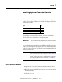
1
User Manual
Time Recorder Extension Module for the Dynamix
2500 Data Collector
Catalog Number 1441-DYN25-MREC
Important User Information
Solid-state equipment has operational characteristics differing from those of electromechanical equipment. Safety
Guidelines for the Application, Installation and Maintenance of Solid State Controls (publication SGI-1.1 available from
your local Rockwell Automation sales office or online at http://www.rockwellautomation.com/literature/) describes some
important differences between solid-state equipment and hard-wired electromechanical devices. Because of this difference,
and also because of the wide variety of uses for solid-state equipment, all persons responsible for applying this equipment
must satisfy themselves that each intended application of this equipment is acceptable.
In no event will Rockwell Automation, Inc. be responsible or liable for indirect or consequential damages resulting from
the use or application of this equipment.
The examples and diagrams in this manual are included solely for illustrative purposes. Because of the many variables and
requirements associated with any particular installation, Rockwell Automation, Inc. cannot assume responsibility or
liability for actual use based on the examples and diagrams.
No patent liability is assumed by Rockwell Automation, Inc. with respect to use of information, circuits, equipment, or
software described in this manual.
Reproduction of the contents of this manual, in whole or in part, without written permission of Rockwell Automation,
Inc., is prohibited.
Throughout this manual, when necessary, we use notes to make you aware of safety considerations.
WARNING: Identifies information about practices or circumstances that can cause an explosion in a hazardous
environment, which may lead to personal injury or death, property damage, or economic loss.
ATTENTION: Identifies information about practices or circumstances that can lead to personal injury or death,
property damage, or economic loss. Attentions help you identify a hazard, avoid a hazard, and recognize the
consequence
SHOCK HAZARD: Labels may be on or inside the equipment, for example, a drive or motor, to alert people that
dangerous voltage may be present.
BURN HAZARD: Labels may be on or inside the equipment, for example, a drive or motor, to alert people that
surfaces may reach dangerous temperatures.
IMPORTANT
Identifies information that is critical for successful application and understanding of the product.
Allen-Bradley, Rockwell Software, Rockwell Automation, Dynamix, Enpac, Emonitor, and TechConnect are trademarks of Rockwell Automation, Inc.
Trademarks not belonging to Rockwell Automation are property of their respective companies.
Table of Contents
Preface
Optional Extension Modules. . . . . . . . . . . . . . . . . . . . . . . . . . . . . . . . . . . . . . . . 5
Additional Resources . . . . . . . . . . . . . . . . . . . . . . . . . . . . . . . . . . . . . . . . . . . . . . . 6
Chapter 1
Installing Optional Extension
Modules
Install Extension Modules . . . . . . . . . . . . . . . . . . . . . . . . . . . . . . . . . . . . . . . . . . 7
Uninstall Extension Modules. . . . . . . . . . . . . . . . . . . . . . . . . . . . . . . . . . . . . . . . 9
Manage Extension Modules . . . . . . . . . . . . . . . . . . . . . . . . . . . . . . . . . . . . . . . 12
Extension Module Battery Status Indicators . . . . . . . . . . . . . . . . . . . . . . . . 13
Chapter 2
Time Recorder Extension
Module
Setting Up and Collecting Time Recorder Measurements . . . . . . . . . . .
Set Up Time Recorder Measurements . . . . . . . . . . . . . . . . . . . . . . . . . .
Recorder Status Indicators . . . . . . . . . . . . . . . . . . . . . . . . . . . . . . . . . . . .
Preview the Measurement . . . . . . . . . . . . . . . . . . . . . . . . . . . . . . . . . . . . .
Record the Measurement. . . . . . . . . . . . . . . . . . . . . . . . . . . . . . . . . . . . . .
Save a Time Recorder Setup and Measurement. . . . . . . . . . . . . . . . . .
Recalling a Setup . . . . . . . . . . . . . . . . . . . . . . . . . . . . . . . . . . . . . . . . . . . . . . . . .
Reviewing Time Recorder Measurements . . . . . . . . . . . . . . . . . . . . . . . . . .
Capture the Review Data Screen . . . . . . . . . . . . . . . . . . . . . . . . . . . . . . .
Back Up Time Recorder Files. . . . . . . . . . . . . . . . . . . . . . . . . . . . . . . . . .
Delete a Time Recorder Measurement and Setup. . . . . . . . . . . . . . . .
Save Files to Your Computer . . . . . . . . . . . . . . . . . . . . . . . . . . . . . . . . . . . . . .
16
16
20
21
22
23
24
25
27
28
29
30
Index
Rockwell Automation Publication 1441-UM005A-EN-P - May 2011
3
Table of Contents
Notes:
4
Rockwell Automation Publication 1441-UM005A-EN-P - May 2011
Preface
This manual describes the Time Recorder Extension Module for the Dynamix
2500 data collector. You install the extension module with the Time Recorder
Secure Digital (SD) card.
See Installing Optional Extension Modules on page 7 for installation
instructions.
When using the Dynamix 2500 data collector and the Time Recorder module,
you can use as a data collector for real-time data acquisition and analysis.
Optional Extension
Modules
These are the optional extension modules for the Dynamix 2500 data collector:
• 1441-DYN25-4C, 4-Channel Activation (1)
The 4-channel activation lets you take 3 and 4 channel magnitude, time
waveform, spectra, and Offroute measurements.
• 1441-DYN25-MBMP Bump Test
A bump test (or hammer test) determines the natural frequencies of a
machine or a structure.
• 1441-DYN25-MBAL Balancing
Balancing application resolves single-plane, two-plane, and static-couple
balances with high precision.
• 1441-DYN25-MFRF Frequency Response Function
The FRF test lets you determine the natural frequencies of a machine as
well as sophisticated information about the frequency response of the
structure being tested.
• 1441-DYN25-MREC Time Recorder
The Time Recorder test uses a the instrument as a data recorder for realtime data acquisition and analysis.
• 1441-DYN25-MRUC Run Up Coast Down
The RUCD test records and analyzes data from intermittent events and
transient vibration signals from non-steady state machines.
See Additional Resources on page 6 for a listing of available publications.
(1) This is an activation license for the Dynamix 2500 data collector.
Rockwell Automation Publication 1441-UM005A-EN-P - May 2011
5
Preface
Additional Resources
These documents contain additional information concerning products from
Rockwell Automation.
Resource
Description
Dynamix 2500 Data Collector User Manual,
publication 1441-UM001
Describes the Dynamix 2500 data collector,
which provides predictive maintenance by
using noise and vibration analysis.
Dynamix 2500 Data Collector Bump Test Extension
Module User Manual, publication 1441-UM002
Describes how determine natural (or resonant)
frequencies of a machine or structure.
Dynamix 2500 Data Collector Frequency Response
Function Extension Module User Manual,
publication 1441-UM003
Describes how to determine the natural
frequencies of a machine or structure by using
modal hammer.
Dynamix 2500 Data Collector Balancing Extension
Module User Manual, publication 1441-UM004
Describes the direct method to balance your
rotating machinery in one or two planes.
Dynamix 2500 Data Collector Run Up Coast Down
Extension Module User Manual, publication
1441-UM006
Describes how to record and analyze data from
intermittent events and transient vibration
signals from non-steady state machines.
Emonitor User’s Guide, publication
EMONTR-UM001
Describes data management for predictive
maintenance services.
Dynamix 2500 Data Collector Kit Release Notes,
publication 1441-RN001
Provides important information on the latest
updates, for example, firmware, certifications,
warnings, and hardware changes for the data
collector.
Dynamix 2500 Data Collector Optional Extension
Modules Release Notes, publication
1441-RN002
Provides important information on how to
install the Optional Extension Modules onto
the Dynamix 2500 data collector.
Industrial Automation Wiring and Grounding
Guidelines, publication 1770-4.1
Provides general guidelines for installing a
Rockwell Automation industrial system.
Product Certifications website, http://www.ab.com Provides declarations of conformity,
certificates, and other certification details.
You can view or download publications at
http://www.rockwellautomation.com/literature. To order paper copies of
technical documentation, contact your local Allen-Bradley distributor or
Rockwell Automation sales representative.
6
Rockwell Automation Publication 1441-UM005A-EN-P - May 2011
Chapter
1
Installing Optional Extension Modules
The data collector uses the Extension Manager to install and uninstall extension
modules. These extension modules are licensed and ordered separately from the
basic entry level product.
Topic
Page
Install Extension Modules
7
Uninstall Extension Modules
9
Manage Extension Modules
12
Extension Module Battery Status Indicators
13
The installation Secure Digital (SD) cards that you receive work with any
Dynamix 2500 data collector. Once you have installed an extension module, the
card is locked so that it can only be used with that instrument.
IMPORTANT
One installation SD card is required for each instrument that needs to
be upgraded.
You can uninstall extension modules if required. When uninstalling an extension
module, you have the option to free up the license so you can install the extension
module on another instrument. This makes the extension module available to be
transferred between units.
IMPORTANT
When ever you re-run the OS Loader software, you will re-load only the
main OS firmware. The OS loader will backup licence files and data, but
not the optional extension modules. Once you have updated the OS
firmware, install the latest version of your optional extension modules.
See the Dynamix 2500 Data Collector User Manual, 1441-UM001, for
more information.
Install Extension Modules
Follow these instructions to install an extension module.
1. Open the base cover at the bottom of the Dynamix 2500 data collector.
2. Place the extension module SD card contact side-up into the unit until it is
firmly seated in place.
3. Close the base cover.
Rockwell Automation Publication 1441-UM005A-EN-P - May 2011
7
Chapter 1
Installing Optional Extension Modules
4. Apply power to the data collector.
5. From the Main Menu, select Setup Utility and press Enter.
6. Press 0 (Shift) to display the second set of functions.
Extension Manager
The Extension Manager function remains on the screen for about three
seconds after releasing 0 (Shift).
7. Press F1 (Extn Mgr).
The Extension Manager screen appears showing the current extension
module installations.
8. Press 0 (Shift) to display the Install Extension function.
8
Rockwell Automation Publication 1441-UM005A-EN-P - May 2011
Installing Optional Extension Modules
Chapter 1
9. Press F2 (Install) to install the new extension module.
When the installation is complete, a confirmation prompt appears.
10. Press F4 (OK).
The new extension module appears in the list.
11. Press F4 (Esc) to exit the Extension Manager screen.
Uninstall Extension
Modules
Follow these instructions to uninstall an extension module.
1. Press 0 (Shift) from the Setup Utility screen to display the Extension
Manager function.
The Extension Manager function remains on the screen for about three
seconds after releasing 0 (Shift).
Extension Manager
Rockwell Automation Publication 1441-UM005A-EN-P - May 2011
9
Chapter 1
Installing Optional Extension Modules
2. Press F1 (Extn Mgr).
The Extension Manager screen appears.
This screen lists the
extension modules
currently installed and the
on the unit.
3. Select the extension module you want to uninstall and press F3 (Select).
F3 (Select) toggles the selection on and off.
10
Rockwell Automation Publication 1441-UM005A-EN-P - May 2011
Installing Optional Extension Modules
Chapter 1
A checkmark appears next to that extension module.
4. Press F1 (Uninstall).
A confirmation message appears.
5. Make sure your installation card is inserted into the instrument.
IMPORTANT
The extension module is uninstalled and the license on the card is
released so that the card can be used to install the extension
module on another Dynamix 2500 data collector.
If the installation card is not inserted in the instrument and no
card, you are is found or the card does not have the extension
module license for the unit, you are prompted to insert the correct
installation card or continue without freeing the license.
6. Press F2 (Yes) to uninstall the extension module.
7. Press F4 (Esc) to exit the Extension Manager screen.
Rockwell Automation Publication 1441-UM005A-EN-P - May 2011
11
Chapter 1
Installing Optional Extension Modules
Manage Extension
Modules
The Dynamix 2500 data collector lets you to hide installed extension modules
from the Main Menu. You may need to hide an advanced extension module icon
from an inexperienced user, for example, RUCD and FRF.
IMPORTANT
Once an extension module is hidden, its icon is not represented on the
Main Menu or displayed in the Dynamix 2500 data collector About
screen.
Follow these instructions to hide or show an extension module icon on the Main
Menu.
1. Press 0 (Shift) on the Setup Utility screen to display the Extension
Manager function.
The Extension Manager function should remain on the screen for
approximately three seconds after releasing 0 (Shift).
2. Press F1 (Extn Mgr). The Extension Manager screen appears.
The Extension Manager displays a list of installed extensions module.
The extension modules that
are hidden are shown in
[square brackets]
The F2 (Hide) toggles between Hide and Show depending if the selected
extension module is hidden or not.
TIP
12
You have to exit and re-enter the Extension Manager after hiding an
extension module to have the Show function appear.
Rockwell Automation Publication 1441-UM005A-EN-P - May 2011
Installing Optional Extension Modules
Chapter 1
3. Select the extension module that you want to hide or show and press F2
(Show/Hide).
TIP
If you want to show or hide multiple extension modules
simultaneously, select each extension module and press F3
(Select).
A checkbox appears next to each selected extension module. If
you select multiple extension modules and some are hidden
while others are shown, F2 (Show/Hide) reflects the status of the
selected extension module.
4. Press F4 (Esc) to exit the Extension Manager.
Extension Module Battery
Status Indicators
The battery status icons show the strength of the battery.
Table 1 - Extension Module Battery Icon Descriptions
Battery Icon
Meaning
Battery status is good: >30% life remaining.
Battery status is low: >10% life remaining.
Battery status is very low: <10% life remaining.
Battery is charging.
Rockwell Automation Publication 1441-UM005A-EN-P - May 2011
13
Chapter 1
Installing Optional Extension Modules
Notes:
14
Rockwell Automation Publication 1441-UM005A-EN-P - May 2011
Chapter
2
Time Recorder Extension Module
The Time Recorder extension module is an optional module for the Dynamix
2500 data collector. You install the extension module with the Time Recorder
Secure Digital (SD) card.
See Installing Optional Extension Modules on page 7 for installation
instructions.
Topic
Page
Setting Up and Collecting Time Recorder Measurements
16
Recalling a Setup
24
Reviewing Time Recorder Measurements
25
Save Files to Your Computer
30
The Time Recorder extension module lets the Dynamix 2500 data collector to be
used as a data recorder for real-time data acquisition and analysis. With the Time
Recorder module, you can record data from Channel X, Channel Y, or from an
external tachometer. The data is stored in a format that can be easily imported
into a software program for analysis.
Below are examples of how you can use the Time Recorder module:
• Analyze very low speed machines.
• Capture run up or coast-down data, intermittent events, and transient
vibration signals from non-steady machines.
• Prevent further damage to a problem machine by recording the vibration
signal for a short time. Then shut down the machine and play the recorded
.wav file to analyze the measurement without the machine running.
• On a ship propulsion system, which uses large amounts of fuel, you can
start the time recorder, run the ship up to full speed, run five minutes at
full speed, and then coast-down. The measurement analysis is performed
on the recorded vibration signal without spending hours of gas turbine
drive time collecting data and resulting fuel consumption.
IMPORTANT
For optimized recording, use the Time Recorder application in
conjunction with an Secure Digital (SD) storage card up to
>16 GB. Saving data to the card greatly increases the amount of
data you can record. The Windows CE Operating system has a 2
GB limitation file size.
Rockwell Automation Publication 1441-UM005A-EN-P - May 2011
15
Chapter 2
Time Recorder Extension Module
Setting Up and Collecting
Time Recorder
Measurements
The Time Recorder extension module records a machine’s vibration signal (time
waveform) as a Microsoft Windows .wav file. The signals from both inputs,
Connector A, Connector B, and the external Tacho (POWER/USB/
TRIGGER) can be digitally recorded and stored for playback at a later date. The
recorded time waveform can be viewed on the data collector for onsite analysis or
it can be copied from the instrument on to a computer for analysis.
Set Up Time Recorder Measurements
Follow these instructions to set up the time recorder measurements.
1. Connect the transducer to the Dynamix 2500 data collector.
2. Attach the transducer to the machine case or structure.
3. From the Main Menu, select Recorder and press Enter.
16
Rockwell Automation Publication 1441-UM005A-EN-P - May 2011
Time Recorder Extension Module
Chapter 2
The Recorder screen appears.
• Setup displays the Time Recorder set-up parameters and begins data
collection.
• Recall lets you recall previously saved Time Recorder Test settings to
perform another Bump Test with the same settings.
• Review Data lets you review saved Time Recorder data.
4. Select Setup and press Enter.
The Recorder - Setup screen appears.
The Save To parameter provides
current maximum recording time
available on an SD card or
internal memory.
5. Select a parameter and press the Right arrow to open a list of choices.
Rockwell Automation Publication 1441-UM005A-EN-P - May 2011
17
Chapter 2
Time Recorder Extension Module
6. Select a parameter value and press the Left arrow.
7. Press F3 (Save) to save the current settings to a file.
See Save a Time Recorder Setup and Measurement on page 23.
Use the descriptions in Table 2 to help you configure the Time Recorder
parameters.
Table 2 - Time Recorder Parameter Descriptions
Parameter
Description
Values/Comments
Input
The input channels for the recorder measurement.
X (default)
This parameter affects the Freq Range maximum frequency setting and
the recording’s maximum recording time.
X and Tacho
• X - 40 KHz maximum Freq Range
• X & Y - 20 KHz maximum Freq Range for each channel
• X & Tacho - 20 KHz maximum Freq Range for each channel
X&Y
X & Y and Tacho
X, Y, & Z
X, Y, Z & R
X Type
Sets the vibration measurement type used on Channel X.
Accel (g) (default)
Your selection determines the available options and engineering units for
subsequent set-up parameters.
Accel (m/s2)
Vel (mm/s)
Vel (ips)
Disp (mils)
Disp (µm)
Volts (V)
Volts AC
Press. (Pa)
Force (N)
Force (lBf)
Sens1
The sensitivity of the transducer in millivolts (mv) per Engineering Units
for channel X.
The sensitivity value is included with the transducer’s documentation or it
may be imprinted on the side of the transducer.
18
Rockwell Automation Publication 1441-UM005A-EN-P - May 2011
mV/EU
Time Recorder Extension Module
Chapter 2
Table 2 - Time Recorder Parameter Descriptions
Parameter
Description
Values/Comments
Range1 (g)
The expected maximum amplitude range value for channel X
measurement.
2…2000
X Type
Sets the vibration measurement type used on channel X.
Accel (g) (default)
Your selection determines the available options and engineering units for
subsequent set-up parameters.
Accel (m/s2)
This parameter is available only when Input is set to X & Y.
Tip: If you want to take more than 2 channel recording you’ll need the
cable. for more than 2 channels, you must use the cable,
cat. no. 1441-DYN25-CBL2CH. When using this cable the
parameters change to offer up to 4 sets of data.
Vel (mm/s)
Vel (ips)
Disp (mils)
Disp (µm)
Volts (V)
Volts AC
Press. (Pa)
Force (N)
Force (lBf)
Sens2
The sensitivity of the transducer in millivolts (mv) per Engineering Units
for channel Y.
mV/EU
This parameter is available only when Input is set to channels X & Y.
The sensitivity value is included with the transducer’s documentation or it
may be imprinted on the side of the transducer.
Range2 (g)
The expected maximum amplitude range value for the channel Y
measurement.
2…2000
This parameter is available only when Input is set to channels X & Y.
Freq Range (Fmax)
The maximum frequency for the measurement. It affects the maximum
recording time and sample frequency. Your Input selection determines the
maximum value to be entered.
•
•
•
•
1000.00 Hz (default)
X- 20 kHz maximum Freq Range
X & Y - 15 kHz maximum Freq Range for each channel
X & Y & Z - 10 kHz
X & Y & Z & R -10 Khz
Tacho inputs affect maximum recording time.
Save To
Rec. Time (s)
Sets the location where recorded data is saved.
Internal (default)
Save the recorded data to the SD card if the .wav files are large. Your
selection affects the maximum recording time.
Card
The number of seconds to record the time waveform signal.
tip: The max Rec.Time is automatically calculated from the amount of free
space available to store the data.
Tip: The maximum Rec.Time is automatically calculated from the amount
of free space available to store the data
Rec. Mode
The method for initiating the data recording. The Record mode works
with the value you set in the Trig. Level parameter.
Manual (default)
X Level
• Manual - Manually start the data recording by pressing F2 (Rec).
• X Level - The recording starts once the unit reaches the amplitude
value entered in the Trig. Level parameter.
Trig. Level (g)
When Rec. Mode is set to X level, the signal level of channel X
automatically triggers and starts the recording.
Rockwell Automation Publication 1441-UM005A-EN-P - May 2011
1.00 (default)
19
Chapter 2
Time Recorder Extension Module
Recorder Status Indicators
The Recorder status indicators, located at the top of the Dynamix 2500 data
collector, operate differently in the Time Recorder module.
Table 3 - Recorder Status Indicators
Status
Indicator
State
Definition
Red
Solid
An error condition has occurred for the current block of
data. The status indicator turns off when the error
condition disappears.
Amber
Solid
An error has occurred during the recording. The status
indicator remains solid even when the error condition
disappears.
The recorded .csv file also contains a flag indicating that
the corresponding .wav file may contain flawed data.
Green
20
Flashing Green
The status indicator toggles on/off for each new data
block.
Rockwell Automation Publication 1441-UM005A-EN-P - May 2011
Time Recorder Extension Module
Chapter 2
Preview the Measurement
You can preview the measurement before you record it to validate the parameter
settings. In Preview mode, the screen continuously updates to display the
channel’s live time waveform signal and overall vibration reading.
Follow these steps to enter Preview mode.
1. From the Recorder Setup screen, press F3 (Start).
The Recorder - Taking Data screen appears.
Cursor amplitude
Cursor time
Preview mode
Overall reading
Channel you are
currently viewing
Messages
The message area is used to display error messages, such as a clipping error,
or to prompt you to press a 1, 2, 3, or 4 to view the other time waveform
channels.
2. If you need to adjust the set-up parameters, press F1 (Back) to return to the
Setup screen.
Rockwell Automation Publication 1441-UM005A-EN-P - May 2011
21
Chapter 2
Time Recorder Extension Module
Record the Measurement
Once you have previewed the measurement and you are satisfied with the
parameter settings, you can record the measurement.
Follow these steps to review the measurement.
1. Press F2 (Rec.) on the Preview screen.
The Recorder - Taking Data screen appears.
Cursor amplitude
Cursor time
Preview mode
Overall reading
Channel you are
currently viewing
Messages
During data recording, the live time waveform freezes on the screen, and
the (recording) time remaining counts down in the message area. If any
errors occur during the recording, an error message is displayed in the
message area.
See Recorder Status Indicators on page 20 for more information.
2. If you need to pause the recording, press F2 (Pause) on the Recorder Taking Data screen.
While paused, the instrument reverts back to Preview mode showing the
live time waveform. The Pause function now becomes the Resume
function.
3. Resume data recording by pressing F2 (Resume).
TIP
The recorded time signal is not displayed continuously while the
recording is paused.
When the recording ends, the Recorder - Save Data screen automatically
appears, allowing you to save the recording to a file.
See Save a Time Recorder Setup and Measurement on page 23.
22
Rockwell Automation Publication 1441-UM005A-EN-P - May 2011
Time Recorder Extension Module
Chapter 2
Save a Time Recorder Setup and Measurement
The time recorder set-up parameters and recorded time waveforms can be saved
to a file that can then be recalled at a later time. The recorded time waveforms are
stored in a .wav file format, and the last block of the recorded .wav file is saved in a
comma separated value (.csv) file format.
You can review .csv time waveform files in the field with the data collector from
the Recorder - Review Data screen. The time waveform .wav audio files can be
imported into vibration analysis software.
IMPORTANT
When data is saved to an SD memory card, only the .wav file is
saved on the card. The .csv file is always saved to the internal
memory in directory: /Mobile Device/Internal Disk/Analyser/
Recorder.
You can save a time recorder set-up and measurement anytime the Save function
is displayed on the screen.
TIP
The Recorder - Save Data screen automatically appears when
the data collector has finished recording the measurement.
Follow these steps to save set-up and measurement data.
1. Press F3 (Save).
The appropriate Recorder - Save screen appears.
Depending where you are in the
process, the Save function either saves
set-up parameters, or saves the set-up
parameters and the recorded data.
Rockwell Automation Publication 1441-UM005A-EN-P - May 2011
23
Chapter 2
Time Recorder Extension Module
2. Do one of the following:
• Save data to an existing file.
a. Select the file, and press F3 (Save).
b. Press F2 (Yes) to overwrite the existing file or press F3 (No) to
return to the Save screen.
• Save data to a new file.
a. Select save reading as and press F3 (Save).
b. Enter a file name by using the keypad or accept the default file name
(current date timestamp).
c. When the entry is complete, press F2 (OK).
IMPORTANT
The set-up parameters are saved along with the measurement
when you press F3 (Save) on the Recorder - Save Data screen.
3. When you are finished, press F4 (Cancel).
Recalling a Setup
You can recall a previously saved setup and use it to record another measurement.
The setup may have been saved only as a setup, or may have been saved with the
recorded measurement.
See Save a Time Recorder Setup and Measurement on page 23.
1. Connect the transducer to the data collector.
2. Attach the transducer to the machine case or structure.
3. From the Time Recorder Main Menu, select Recall and press Enter.
The Recorder - Load Setup screen appears.
4. Select the file you want to recall and press F3 (Open).
24
Rockwell Automation Publication 1441-UM005A-EN-P - May 2011
Time Recorder Extension Module
Chapter 2
The Recorder - Setup screen appears.
See Set Up Time Recorder Measurements on page 16 for assistance in
setting up the parameters.
5. To preview the measurement and start recording, press F3 (Start).
• See Preview the Measurement on page 21.
• See Record the Measurement on page 22.
Reviewing Time Recorder
Measurements
You can review previously recorded measurements with the Dynamix 2500 data
collector. Only a small portion from the end of the recorded data can be reviewed
with the data collector. To review the entire data file, you must transfer the file to
your computer.
See Save a Time Recorder Setup and Measurement on page 23.
To review recorded measurements with your instrument, follow these steps.
1. From the Time Recorder Main Menu, select Recorder and press Enter.
Rockwell Automation Publication 1441-UM005A-EN-P - May 2011
25
Chapter 2
Time Recorder Extension Module
The Recorder screen appears.
2. Select the filename that you want review and press F3 (Open).
The measurement appears.
•
•
•
•
26
Press F1 (Print) to print the screen.
Press F2 (Prev) to review the previous saved file.
Press F3 (Next) to review the next saved file.
Press F4 (Back) to return to the Recorder - Review Data screen.
Rockwell Automation Publication 1441-UM005A-EN-P - May 2011
Time Recorder Extension Module
Chapter 2
Capture the Review Data Screen
The Review Data screen can be saved as a bitmap (.bmp) image to internal
memory or an SD storage card.
1. Press 0 (Shift) and 7.
The Print popup screen appears.
2. Press F2 (Card) to create and save the .bmp file to an SD card.
3. Press F3 (Internal) to save the .bmp file on the instrument.
Rockwell Automation Publication 1441-UM005A-EN-P - May 2011
27
Chapter 2
Time Recorder Extension Module
Back Up Time Recorder Files
You can back up files either from the Review Data screen or the Recall Data
screen.
Follow these steps to back up your files.
1. From the Time Recorder Main Menu, select Review Data or Recall Data
and press Enter.
The appropriate Recorder screen appears.
2. Select a file or select -all- (to backup all the files).
3. Press 0 (Shift) to display a second set of functions.
4. Press F1 (Backup).
The specified files are automatically copied to the \Storage
Card\Analyser\Recorder directory on the SD storage card that is in the
data collector.
28
Rockwell Automation Publication 1441-UM005A-EN-P - May 2011
Time Recorder Extension Module
Chapter 2
Delete a Time Recorder Measurement and Setup
Follow these steps to delete a time recorder and setup.
1. Select Recorder on the Main Menu and press Enter.
The Recorder screen appears.
2. Select Review Data to delete a measurement or Recall Data to delete a
setup and press Enter.
The Recorder screen appears.
3. Select the appropriate filename or select all to delete all the files.
4. Press 0 (Shift) to display another set of functions.
Rockwell Automation Publication 1441-UM005A-EN-P - May 2011
29
Chapter 2
Time Recorder Extension Module
5. Press F4 (Delete) to delete the selected file from the data collector.
6. Press F2 (Yes) to delete.
Save Files to Your Computer
You can save you files to your computer by using the ActiveSync connection.
Follow these instruction to back up your data to your computer by using the
ActiveSync software.
1. Connect the instrument with the USB cable to you computer.
ActiveSync automatically senses the connection and displays the
Connected – Synchronized message.
See the Dynamix 2500 Data Collector User Manual,
publication 1441-UM001, for information about ActiveSync
communication.
30
Rockwell Automation Publication 1441-UM005A-EN-P - May 2011
Time Recorder Extension Module
Chapter 2
2. Click Explore.
The contents of the data collector (mobile device) appears.
3. From the Windows Explorer window, copy the stored measurement files
(.csv files) from the data collector’s Internal Disk/Analyzer folder to a
folder on your computer.
Rockwell Automation Publication 1441-UM005A-EN-P - May 2011
31
Chapter 2
Time Recorder Extension Module
Notes:
32
Rockwell Automation Publication 1441-UM005A-EN-P - May 2011
Index
A
ActiveSync 30
B
back up files 28
Balancing 15
battery
status icons 13
battery status icons 13
Range1 19
Range2 19
Rec. Mode 19
Rec. Time 19
Recorder - Load Setup screen 24
Recorder - Save screens 23
Recorder - Setup screen 17
Recorder - Taking Data screen 21, 22
related publications 6
reviewing data
time recorder 25
C
collecting data
time recorder measurements 16
configure
time recorder parameters 18
E
S
Save To 19
saving 15, 18, 23, 30
Sens1 18
Sens2 19
storage card 28
error 20
Extension Manager 7
F
Freq Range 19
I
Input 18
install extension module 7
L
license
extension module 11
M
manage extension modules 12
hide and show 12
measurement
delete 29
preview 21
record 22, 25
review 23
P
parameter 17
preview 22
print screens 27
T
Time Recorder
deleting data 29
Load Setup screen 24
overview 16
pausing the recording 22
recalling setup 24
recording data 22
reviewing data 25
save measurement 23
Save screens 23
save setup 23
setting up 16
Setup screen 17
status indicators 20
Taking Data screen 21, 22
Time Recorder Setup parameters 18, 19
Freq Range 19
Input 18
Range1 19
Range2 19
Rec. Mode 19
Rec. Time 19
Save To 19
Sens1 18
Sens2 19
Trig Level 19
Trig Level 19
U
uninstall extension module 9
USB cable 30
R
Rockwell Automation Publication 1441-UM005A-EN-P - May 2011
33
Index
Notes:
34
Rockwell Automation Publication 1441-UM005A-EN-P - May 2011
Rockwell Automation Support
Rockwell Automation provides technical information on the Web to assist you in using its products.
At http://www.rockwellautomation.com/support/, you can find technical manuals, a knowledge base of FAQs, technical and
application notes, sample code and links to software service packs, and a MySupport feature that you can customize to make the
best use of these tools.
For an additional level of technical phone support for installation, configuration, and troubleshooting, we offer TechConnect
support programs. For more information, contact your local distributor or Rockwell Automation representative,
or visit http://www.rockwellautomation.com/support/.
Installation Assistance
If you experience a problem within the first 24 hours of installation, review the information that is contained in this manual.
You can contact Customer Support for initial help in getting your product up and running.
United States or Canada
1.440.646.3434
Outside United States or
Canada
Use the Worldwide Locator at http://www.rockwellautomation.com/support/americas/phone_en.html, or contact
your local Rockwell Automation representative.
New Product Satisfaction Return
Rockwell Automation tests all of its products to ensure that they are fully operational when shipped from the manufacturing facility.
However, if your product is not functioning and needs to be returned, follow these procedures.
United States
Contact your distributor. You must provide a Customer Support case number (call the phone number above to obtain
one) to your distributor to complete the return process.
Outside United States
Please contact your local Rockwell Automation representative for the return procedure.
Documentation Feedback
Your comments will help us serve your documentation needs better. If you have any suggestions on how to improve this document,
complete this form, publication RA-DU002, available at http://www.rockwellautomation.com/literature/.
Rockwell Otomasyon Ticaret A.Ş., Kar Plaza İş Merkezi E Blok Kat:6 34752 İçerenköy, İstanbul, Tel: +90 (216) 5698400
Publication 1441-UM005A-EN-P - May 2011 36
Copyright © 2011 Rockwell Automation, Inc. All rights reserved. Printed in the U.S.A.