1
Contents
1.
FEATURES
2
2.
CONTROLS
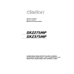
MAIN UNIT
3
3
DISPLAY
3.
BUTTON TERMINOLOGY
3
4
4
Names of the Buttons and Their Functions
4.
PRECAUTIONS
6
5.
6.
HANDLING COMPACT DISCS
DCP (Detachable Control Panel)
7
8
7.
REMOTE CONTROL
9
Inserting the Battery
Functions of Remote Control Unit Buttons
9
8.
10
OPERATIONS
11
11
13
14
16
18
21
Basic Operations
Radio Mode Operations
CD/MP3IWMA Mode Operations
USB Mode Operation
Operation Common to CD and USB Drive
Operations Common to Each Mode
9.
TROUBLESHOOTING
22
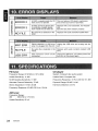
10. ERROR DISPLAYS
24
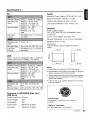
11. SPECIFICATIONS
24
• USB slot on control panel
• MP3 and WMA compatible with ID3-TAG display
• "Z-ENHANCER" sound customization & "MAGNA BASS EX" dynamic bass enhancement
rnJDO~@
DIGITAL AUDIO
mp3
ID3TAG
Be sure to unfold and read the nextpage.
Veuillez deplorer at VOIlS relerer /a page sliivanta.
Cerciorese de desplegar y de leer la pagina siguiente.
a
2
DB365USB
~
/ UNIDAD PRINCIPAL
[ROTARY]
r -........................... [~]
[SCN]
[CD SLOT]
~~I~1
[ROM]
[0]
[T]
D~PLAY/AFACHEUR/WSUAL~ADOR
••••• ••••• ••••• ••••• ••••• ••••• ••••• ••••• Z c
~ i:ili i:ili i:ili i:ili·i:ili i:ili·i:ili i:ili ~
~~~~~~~~~~~~~~~~~~
\M="'B~
:::~: :::u
: :
L.!IJ5.
~ •••••
••••• :::~:
••••• :::~:.:::~:
••••• ••••• :::~:·:::u
•••••• ••••• :::~:
•••••
p- :=:
~ALL···SCNRPTRDMMANU
mSTm MUTE
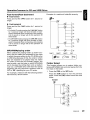
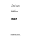
Note: Be sure to unfold this page and refer to the front diagrams as you read each chapter.
Remarque; Veuillez deplier cette page at vous referer aux scMmas quand vous lisez chaque chapitre.
Nota: Cuando lea los capitulos, despliegue esta pagina y consulte los diagramas.
3
DB365USB
~
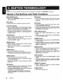
Note:
• Be sure to read this chapter referring to the front diagrams of chapter "2. CONTROLS" on page 3.
Names of the Buttons and Their Functions
[RELEASE] button
[Z] button
• Press the [RELEASE] button to unlock the
detachable panel.
• Press the button to select one of the 3 types
of sound characteristics already stored in
memory.
[A] button
• Press the button to switch to the ADJ mode.
[ 1'llII'llII, ~I] buttons
• Select a station while in the Radio mode or select
a track when listening to a CD/USB. These
buttons is used to make various settings.
• Press and hold the button for 1 second or longer
to enter the fast-forward or fast-backward in
CD/USB mode.
[A-M] button
• Press the button to switch to the Audio mode
(Bass, Treble, Balance, Fader).
• Press and hold for 1 second or longer to turn on
or off the M-B EX mode.
[BND] button
• Switch the band, seek tuning or manual tuning
while in the Radio mode.
• Playa first track while in the CD/MP3IWMA or
USB mode.
[lSR] button
• Recall ISR radio station in memory.
• Press and hold for 2 seconds or longer: Store current station into ISR memory (Radio mode only).
[T] button
• Press the button to switch the track titles, while
in the MP3IWMAlUSB mode.
• Press and hold the button for 1 second or longer
to scroll the title during title display, while in the
MP3IWMA or USB mode.
[UP], [ON] buttons
• Select the Folder (MP3/WMA disc or USB
drive).
• Press the button to select CD-DA or MP3IWMA
on a multi-session disc.
[ROM] button
• Perform random play while in the CD/MP3IWMA
or USB mode.
• Press and hold the button for 1 second or longer
to perform folder random play while in the MP3/
WMA or USB mode.
[SCN] button
• Perform scan play for 10 seconds of each track
while in the CD/MP3IWMA or USB mode.
• Press and hold the button for 1 second or
longer to perform folder scan play while in the
MP3IWMA or USB mode.
[RPT] button
[SRC] button
• Press the button to turn on the power.
Press and hold the button for 1 second or longer
to turn off the power.
• Switch the Operation mode among the Radio
mode, etc.
• Repeat play while in the CD/MP3IWMA or USB
mode.
• Press and hold the button for 1 second or longer
to perform folder repeat play while in the MP3/
WMA or USB mode.
[DIRECT] buttons
[0] button
• During Radio/CD mode, switch the display
indication (Main display, Clock display).
• During MP3IWMAlUSB mode, switch the display
indication in the following order:
Track No.lPlay time
Folder No./Track No.
Title Display Clock Display Track No.1
Play time...
-+
4
-+
DB365USB
-+
-+
• Store a station into memory or recall it directly
while in the Radio mode.
[USB PORT]
• USB drive insertion port.
Names of the Buttons and Their
Functions
[~] button
• Eject a CD when it is loaded into the unit.
[CD SLOT]
• CD insertion slot.
[SENSOR]
• Receiver for remote control unit.
• Operating range: 30° in all directions.
[ ~II] button
• Perform preset scan while in the Radio mode.
Press and hold the button for 2 seconds or
longer to perform auto store.
• Play or pause a track while in the CD/MP31
WMA or USB mode.
[ROTARY] knob
• Adjust the volume by turning the knob clockwise
or counterclockwise.
• Use the knob to perform various settings.
DB365USB
5
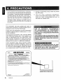
During extreme cold temperatures, condensation may form on the disc and/or the optical part
of the player. If the disc exhibits condensation,
carefully wipe off the disc with a soft cloth. In
the event the disc still does not play properly,
eject the disc and allow the condensation to
disappear naturally from the optical parts of
the player. Radio, Auxiliary and USB functions
can still be during this time which may take up
to an hour.
This equipment has been tested and found to
comply with the limits for a Class B digital device,
pursuant to Part 15 of the FCC Rules.
These limits are designed to provide reasonable
protection against harmful interference in a residential installation.
This equipment generates, uses, and can radiate
radio frequency energy and, if not installed and
used in accordance with the instructions, may
cause harmful interference to radio communications. However, there is no guarantee that interference will not occur in a particular installation.
If this equipment does cause harmful interference to radio or television reception, which can
be determined by turning the equipment off and
on, the user is encouraged to consult the dealer
or an experienced radiolTV technician for help.
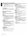
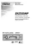
MODEL
D8365US8
2. Driving on extremely bumpy roads may cause
the CO to skip.
3. This unit uses a precision mechanism.
Even in the event that trouble arises, never
open the case, disassemble the unit, or
lubricate the rotating parts.
USE OF CONTROLS, ADJUSTMENTS,
OR PERFORMANCE OF PROCEDURES
OTHER THAN THOSE SPECIFIED HEREIN,
MAY RESULT IN HAZARDOUS RADIATION
EXPOSURE.
THE COMPACT DISC PLAYER SHOULD NOT
BE ADJUSTED OR REPAIRED BY ANYONE
EXCEPT PROPERLY QUALIFIED SERVICE
PERSONNEL
"Ni·JjMe·iil,U'i·Jj'l}i#jtt
CHANGES OR MODIFICATIONS TO THIS
PRODUCTNOTAPPROVEDBYTHEMAN~
FACTURER WILL VOID THE WARRANTY
AND WILL VIOLATE FCC APPROVAL
clarion
e
12V
GROUND
AM 530-1710kHz / FM 87.9-107.9MHz
TH IS OEVICE COMPLIES WITH PART 15 OF THE FCC RULES.
OPERATION IS SUBJECT TO THE FOLLOWING TWO CONDITIONS:
(1) THIS DEVICE MAY NOT CAUSE HARMFUL INTERFERENCE, AND
(2)
~i~~~~ifJN~~~H~'fCJN ~~0~'fG~6~~~~~6 ~~~~IXil~~NCLUDING
THIS PRODUCTION COMPLIES WITH DHHS RULES 21 CFR SUBCHAPTER
J APPLICABLE AT DATE OF MANUFACTURE.
CLARION CO., LTD.
50 KAMITOOA,TODA-SHI,SAITAMA-KEN,JAPAN
This product includes technology owned by Microsoft Corporation and cannot
be used or distributed withem a license from MSlGP
MANUFACTURED: CLARION MALAYSIA
Bottom View of Source Unit
SERIAL No.
PE-2872B
6
DB365USB
276-0080-00
Clarion Co.,Ltd.
MADE IN MALAYSIA
This unit has been designed specifi
back of compact discs bearing the
other discs can be played.
II for playmark. No
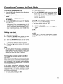
Note on compact discs
Never stick labels on the surface of the compact
disc or mark the surface with a pencil or pen.
To remove the compact disc from its storage
case, press down on the center of the case and
lift the disc out, holding it carefully by the edges.
Removing the disc
I
Proper way to hold
the compact disc
~
Always handle the compact disc by the edges.
Never touch the surface.
Do not use any solvents such as commercially
available cleaners, anti-static spray, or thinner to
clean compact discs.
No
To remove fingermarks and dust, use a soft cloth,
and Wipe in a straight line from the center of the
compact disc to the circumference.
Do not use compact discs that have large scratches, are misshapen, or cracked, etc. Use of such
discs will cause mlsoperation or damage.
New discs may have some roughness around
the edges. The unit may not work or the sound
may skip if such discs are used. Use a ball-point
pen, etc. to remove roughness from the edge of
the disc.
Roughness
Do not expose compact discs to direct sunlight or
any heat sou rce.
~..
Note:
• Do not use commercially available CD protection sheets or discs equipped with stabilizers, etc. These may
get caught in the internal mechanism and damage the disc.
DB365USB
7
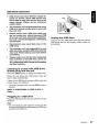
The control panel can be detached to prevent
theft. When detaching the control panel, store it
in the DCP (Detachable Control Panel) case to
prevent scratches.
We recommend taking the DCP with you when
leaving the car.
Storing the DCP in the DCP case
Hold the DCP, in the orientation as shown in the
figure below, and put it into the supplied DCP
case. (Ensure the DCP is in the correct orientation.)
DCP
Removing the DCP
1. Press the [SRC] button for 1 second or longer
to switch off the power.
2. Press in the [RELEASE] button.
~
DCP case
[RELEASE] button
1(1
*
The DCP is unlocked.
•
The DCP can easily be damaged by impact.
After removing it, be careful not to drop it
or SUbject it to strong shocks.
•
If the FLIP DOWN PANEL is kept open, the
DCP may drop due to vibration of the car.
This may result in damage to the DCP. So
close the FLIP DOWN PANEL or remove the
DCP and store in the case.
3. Pull the DCP toward you and remove it.
•
The connector connecting the main unit and
the DCP is an extremely important part. Be
careful not to damage it by pressing on it
with fingernails, pens, screwdrivers, etc.
Attaching the DCP
1. Insert the right side of the DCP into the main
unit.
2. Insert the left side of the DCP to attach into
the main unit.
Note:
• If the DCP is dirty, wipe off the dirt with a soft, dry
cloth only.
8
DB365USB
OND
[SRC]
•
l II
~II
II"~"·'
II 8GJG
Mur:,..>fsR
DISP
I+l~
[ISRlj
DISC UP
TOP
I+C
[i], [f]
[MUTE]
G
II
SEARCH
,
8QG
RP~DM
SCN
PS/AS
TV/VTR
[SCN]
II
I
II
[BND]
[~II]
[~],[~]
[DISP]
[ROM]
[RPT]
clarion
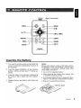
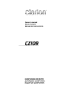
• WIRELESS REMOTE CONTROllER •
Inserting the Battery
1. Turn over the remote control unit and slide the
cover in the direction indicated by the arrow in
the illustration.
2. Insert the battery (CR2025) into the insertion
guides, with the printed side (+) facing upwards.
3. Press the battery in the direction indicated by
the arrow so that it slides into the compartment.
4. Replace the cover and slide in until it clicks into
place.
Notes:
Misuse may result in rupture of the battery, producing leakage of fluid and resulting in personal injury
or damage to surrounding materials. Always follow
these safety precautions:
• Use only the designated battery.
• When replacing the battery, insert properly, with
+/- polarities oriented correctly.
• Do not subject battery to heat, or dispose of in fire or
water. Do not attempt to disassemble the battery.
• Dispose of used batteries properly.
DB365USB
9
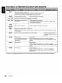
Functions of Remote Control Unit Buttons
Press the button to power on.
Press and hold the button for 1 second or longer: Power off.
Switch among Radio, CO/MP3IWMA, USB and AUX.
[BND]
[!], [T]
[I~~], [~~I]
Switch reception band.
Play the first track. Top play.
Increase and decrease volume (in all modes).
Move preset channels up
and down.
Move tracks up and down.
Press and hold the button for 1 second or longer: Fastforward/fast-backward.
[~II]
Switch between playback and pause.
[MUTE]
[lSR]
*
10
Recall ISR radio station in memory.
Press and hold for 2 seconds or longer: Stores current station into ISR memory (radio
mode only).
[DISP]
Switch among main display and clock display.
[SeN]
Preset scan.
Press and hold the button
for 2 seconds or longer:
Auto store.
Scan play.
Press and hold the button for 1 second or longer to
perform folder scan play while in the MP3IWMA or USB
mode.
[RPT]
No function.
Repeat play.
Press and hold the button for 1 second or longer to
perform folder repeat play while in the MP3IWMA or USB
mode.
[ROM]
No function.
Random play.
Press and hold the button for 1 second or longer to
perform folder random play while in the MP3IWMA or
USB mode.
Switch among main display, title display and clock
display.
Some of the corresponding buttons on the main unit and remote control unit have different functions.
DB365USB
Basic Operations
Note: Be sure to read this chapter referring to the front diagrams of
chapter "2. CONTROLS" on page 3.
Be sure to lower the volume before switching off the unit power or the ignition key. The
unit remembers its last volume setting. If
you switch the power off with the volume up,
when you switch the power back on, the sudden loud volume may hurt your hearing and
damage the unit.
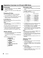
• Radio/CD Mode:
Main display ~ Clock display ~ Main display
• MP3IWMAlUSB Mode:
Main-1 display (Track No., play time) ~ Main2 Display (Folder No., Track No.) ~ Title
Display ~ Clock Display ~ Main-1 Display...
*
Turning on/off the power
Note:
• Be careful about using this unit for a long time
without running the engine. If you drain the car's
battery too far, you may not be able to start the
engine and this can reduce the service life of the
battery.
1. Press the [SRC] button.
2. The illumination and display on the unit light
up. The unit automatically remembers its last
Operation mode and will automatically switch
to display that mode.
3. Press and hold the [SRC] button for 1 second
or longer to turn off the power for the unit.
Selecting a mode
1. Press the [SRC] button to change the Operation mode.
2. Each time you press the [SRC] button, the Operation mode changes in the following order:
Radio mode ~ CDIMP3IWMA mode
(USB mode) ~ AUX mode ~ Radio
mode...
~
Notes:
• If the CD mode is selected when no disc is inserted,
the display shows "NO DISC".
• If no USB drive is inserted, USB mode will not be
displayed.
Once selected, the preferred display becomes the
display default. When a function adjustment such
as volume is made, the screen will momentarily
switch to that function's display, then revert back
to the preferred display several seconds after the
adjustment.
Adjusting the volume
Turning the [ROTARY] knob clockwise increases
the volume; turning it counterclockwise decreases the volume.
*
The volume level is from 0 (minimum) to 33 (maximum).
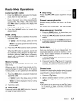
Audio mode adjustments
1. Press the [A-M] button to select the Adjustment
mode. The mode switches as follows each time
the [A-M] button is pressed:
BASS
mode
~
TREB
~
BAL
~
FAD ~ Previous
2. Turning the [ROTARY] knob to adjust the
selected Audio mode.
BASS (Bass) : Adjustment range : -7 to +7
TREB (Treble): Adjustment range: -7 to +7
BAL (Balance): Adjustment range: L13 to R13
FAD (Fader)
*
: Adjustment range: F12 to R12
The display returns to the previous mode 7
seconds after the adjustment.
Note:
• Bass and Treble can only be adjusted when the
"Z-Enhancer" is off.
Switching the display
Press the [0] button to select the desired display.
Each time you press the [0] button, the display
switches in the following order:
DB365USB
11
Basic Operations
Setting the Z-Enhancer
Adjusting MAGNA BASS EX
This unit are provided with 3 types of sound tone
effects stored in memory. Select the one you prefer.
The MAGNA BASS EX does not adjust the low
sound area like the normal sound adjustment
function, but emphasizes the deep bass sound
area to provide you with a dynamic sound.
* The factory default setting is "Z-EHCR OFF".
Each time you press the [Z] button, the tone effect changes in the following order:
"Z-EHCR OFF" ~ "Z-EHCR 1" ~ "Z-EHCR 2"
"Z-EHCR 3" ~ "Z-EHCR OFF" ...
• Z-EHCR 1
: bass emphasized
• Z-EHCR 2
: bass and treble emphasized
• Z-EHCR 3
: bass and treble emphasized
mid de-emphasized
• Z-EHCR OFF : no sound effect
Adjusting the balance
1. Press the [A-M] button and select "BAL 0".
2. Turning the [ROTARY] knob clockwise emphasizes the sound from the right speaker; turning
it counterclockwise emphasizes the sound from
the left speaker.
*
The factory default setting is "SAL 0".
(Adjustment range: L13 to R13)
3. When the adjustment is complete, press the
[A-M] button several times until the Function
mode is reached.
Adjusting the fader
1. Press the [A-M] button and select "FAD 0".
2. Turning the [ROTARY] knob clockwise emphasizes the sound from the front speakers;
turning it counterclockwise emphasizes the
sound from the rear speakers.
*
The factory default setting is "FAD 0".
(Adjustment range: F12 to R12)
3. When the adjustment is complete, press the
[A-M] button several times until the Function
mode is reached.
12
DB365USB
*
The factory default setting is off.
1. Press and hold the [A-M] button for 1 second or
longer to turn on the MAGNA BASS EX effect.
"M-B EX" lights in the display.
2. Press and hold the [A-M] button for 1 second or
longer to turn off the MAGNA BASS EX effect.
"M-B EX" goes off from the display.
AUX function
This system has external input jacks so you can
listen to sounds and music from external devices
connected to this unit.
1. Press the [SRC] button and select the AUX
mode to activate the AUX function.
Radio Mode Operations
Listening to the radio
•
1. Press the [SRC] button and select the Radio
mode, then the radio will be on.
Press the [I~~ , ~I] button to perform manual
tuning.
2. To select a preset band, press the [BND]
button, then select one of the preset bands
such as FM1, FM2, FM3 or AM. Every time
the [BND] button is pressed, the display will
change as:
FM1-+FM2 -+ FM3 -+ AM -+ FM1 ...
3. Press the [I~~, ~I] button to tune in the
desired station.
Seek tuning
1. Press the [BND] button and select the desired
band (FM or AM).
*
If "MANU" is lit in the display, press and hold
the [BND] button for 1 second or longer.
"MANU" in the display goes off and seek tuning
is now available.
2. Press the [ I~~ , ~~I ] button to start automatic
station tuning.
When the [~I] button is pressed, search will
be performing in the direction of higher frequencies. When the [ I~] button is pressed,
search will be performed in the direction of
lower frequencies.
Manual tuning
There are 2 ways available: Quick tuning and
step tuning.
When you are in the step Tuning mode, the frequency changes one step at a time. In the quick
Tuning mode, you can quickly tune the desired
frequency.
1. Press the [BND] button and select the desired
band (FM or AM).
*
If "MANU" is not lit in the display, press and hold
the [BND] button for 1 second or longer.
"MANU" is lit in the display and manual tuning
is now available.
2. Tune into a station.
• Quick tuning:
Press and hold the [I~, ~I] button for 1 second
or longer to begin station tuning.
Step tuning:
Preset memory function
Preset memory function can store up to 24 stations:
Six stations for each of FM1, FM2, FM3 and AM.
Manual memory function
1. Press the [BND] button, to select a band you
want to store in the memory.
2. Press the [ I~ , ~~I] button to tune into a desired
station.
3. Press and hold one of the [DIRECT] buttons for
2 seconds or longer to store the current station
into preset memory.
Auto store
Auto store is a function for storing up to 6 stations
that are automatically tuned in sequentially. If 6
receivable stations cannot be received, a previously stored station remains un-overwritten at
the memory position.
1. Press the [BND] button and select the desired
band (FM or AM).
2. Press and hold the [ ~II ] button for 2 seconds
or longer. The stations with good reception are
stored automatically to the preset channels.
Preset scan
Preset scan receives the stations stored in preset
memory in order. This function is useful when
searching for a desired station in memory.
'1. Press the [~II] button.
2. When a desired station is tuned in, press the
[~II] button again to continue receiving that
station.
Note:
• Be careful not to press and hold the [ ~II ] button
for 2 seconds or longer, otherwise the auto store
function is ,engaged and the unit starts storing stations.
DB365USB
13
Radio Mode Operations
CD/MP3IWMA Mode
Operations
Recalling a preset station
What is MP3?
A total of 24 preset positions (6-FM1, 6-FM2, 6FM3, 6-AM) exists to store individual radio stations in memory. Pressing the corresponding [DIRECT] button recalls the stored radio frequency
automatically.
MP3 is an audio compression method and classified into audio layer 3 of MPEG standards. This
audio compression method has penetrated into
PC users and become a standard format. This
MP3 features the original audio data compression to about 12 percent of its initial size with a
high quality sound. This means that about 10
music CDs can be recorded on a CD-R disc or
CD-RW disc to allow a long listening time without
having to change CDs.
1. Press the [BND] button and select the desired
band (FM or AM).
2. Press the corresponding [DIRECT] button to
recall the stored station.
*
Press and hold one of the [DIRECT] buttons
for 2 seconds or longer to store that station into
preset memory.
Instant station recall (lSR)
Instant station recall is a special radio preset that
instantly accesses a favorite radio station at a
touch of a button. The ISR function even operates with the unit in other modes.
• ISR memory
1. Select the station that you wish to store in ISR
memory.
2. Press and hold the USR] button for 2 seconds
or longer.
•
Recalling a station with ISR
In any mode, press the USR] button to turn on the
radio function and. tune the selected radio station. "ISR" appears in the display. Press the USR]
button again to return to the previous mode.
What is WMA?
WMA is the abbreviation of Windows Media Audio, an audio file format developed by Microsoft
Corporation.
Notes:
• If you playa file with DRM (Digital Rights Management) for WMA remaining ON, no audio is output.
• Windows Media™, and the Windows® logo are
trademarks, or registered trademarks of Microsoft
Corporation in the United States and/or other
countries.
• To disable DRM
(Digital Rights Management):
1. When using Windows Media Player 8, click
on TOOLS ~ OPTIONS ~ COpy MUSIC
tab, then under COPY SETTINGS unclick the
check box for PROTECT CONTENT. Then,
reconstruct files.
2. When using Windows Media Player 9, click
on TOOL ~ OPTIONS ~ MUSIC RECORD
tab, then under Recording settings, unclick the
check box for RECORD PROTECTED MUSIC.
Then, reconstruct files.
3. When using Windows Media Player 10, click on
TOOL ~ OPTIONS ~ RIP MUSIC tab, then
under Rip settings, unclick the check box for
COpy PROTECT MUSIC. Then, reconstruct
files. Personally constructed WMA files are
used at your own responsibility.
•
Precautions when creating MP3IWMA
disc
Please refer to the usable sampling rates and
bit rates of chapter "11. SPECIFICATIONS" on
page 24.
14
DB365USB
CD/MP3IWMA Mode Operations
• File extensions
•
Always add a file extension ".MP3" or ".WMA"
to MP3 or WMA file by using single byte letters.
If you add a file extension other than specified
or forget to add the file extension, the file cannot be played.
Disc-In-Play function
As long as the ignition key is turned to the ON
or ACC position, this function allows you to turn
the power to the unit and start playing the disc
automatically when the disc is inserted even if
the power is not turned on.
• Logical format (File system)
1. When writing MP3IWMA file on a CD-R disc or
CD-RW disc, please select "IS09660 level 1, 2
or JOLIET or Romeo" as the writing software
format. Normal play may not be possible if the
disc is recorded on another format.
2. The folder name and file name can be displayed as the title during MP3IWMA play but
the title must be within 28 single byte alphabetical letters and numerals (including an extension).
3. Do not affix a name to a file inside a folder
having the same name.
• Folder structure
1. A disc with a folder having more than 8 hierarchical levels will be impossible.
• Number of files or folders
1. Up to 255 files can be recognized per folder.
Up to 255 files can be played.
Note:
• The company will not guarantee any unexpected
result caused by exceeding the files limitation.
2. Tracks are played in the order that they were
recorded onto a disc. (Tracks might not always
be played in the order displayed on the PC.)
3. Some noise may occur depending on the type
of encoder software used while recording.
•
Do not try to put your hand or fingers in the
disc insertion slot. Also never insert foreign
objects into the slot.
•
Do not insert discs where adhesive comes
out from cellophane tape or a rental CD
label, or discs with marks where cellophane
tape or rental CD labels were removed. It
may be impossible to extract these discs
from the unit and they may cause the unit
to break down.
Backup eject function
Just pressing the [~] button ejects the disc even
if the power to the unit was not turned on. Remove the disc after it is ejected.
Notes:
• If you force a CD into before auto reloading, this
can damage the CD.
• If a CD (12 cm) is left in the ejected position for 15
seconds, the CD is automatically reloaded. (Auto
reload).
• 8 cm CDs are not auto reloaded. Be sure to remove
it when ejected.
Listening to a disc already loaded
in the unit
Press the [SRC] button to select the CD/M P31
WMAmode.
CD-DAlMP3IWMA selection on
multi-session CD
When the unit enters the CD/MP3IWMA mode,
play starts automatically.
1. If a multi-session CD which contains CD-DA
and MP3IWMA files is being inserted, user can
select either CD-DA or MP3IWMA files to be
played.
DISC" appears in the title display.
Note:
• CD-DA files will always be the first to be played
while MP3IWMA files will be playing subsequently.
If there is no disc loaded, the indication "NO
Radio ~ CDIMP3IWMA ~ (USB) ~ AUX ~
Radio...
2. Press the [UP] button will move to the next
folder and MP3IWMA files to be played. Press
the [ON] button at the time will return to CD-DA
playing files.
DB365USB
15
CD/MP3IWMA Mode Operations
USB Mode Operation
Loading a CD
What is USB?
Insert a CD into the center of the CD SLOT with
the labeled side facing up. "LOADING" appears
in the display, the CD plays automatically after
loading.
USB is the abbreviation of Universal Serial Bus,
an external bus standard that supports data
transfer rates of 12Mbps. The main unit is USB
2.0 compatible. (It is compliant with Universal Serial Bus Revision 1.1 specification, which is Full
Speed supported but not running at High-Speed).
This means that the transfer rates only supports
until 12Mbps, which is the maximum speed of
USB1.1. USB also support hot plugging, which is
the ability to add and remove devices to a main
unit while the unit is running and automatically
recognize the change.
Notes:
• Never insert foreign objects into the CD SLOT.
• If the CD is not inserted easily, there may be another CD in the mechanism or the unit may require
service.
.
.
rnm~@
• DIscs not beanng the
mark and CD-ROMs
cannot be played by this unit.
DIGITALAUDID
• Some CDs recorded in CD-R/CD-RW mode may
not be usable.
Loading 8 cm compact discs
*
*
No adapter is required to play an 8 cm CD.
Insert the 8 cm CD into the center of the insertion
slot.
For CD/MP3IWMA playback, please refer to "Operations Common to CD and USB Drive".
Supported audio files playback
Only MP3 and WMA files are currently supported. For further information on MP3IWMA playback, please refer to "Operations Common To
CD and USB Drive".
Hot plugging function
When the unit is power on, this function allows
you to start playing the tracks automatically when
the USB drive is inserted.
16
DB365USB
•
Do not try to put your hand or fingers in
the USB insertion port. Also never insert
foreign objects into the port.
•
Do not insert USB devices other than "USB
mass storage class" as this will have no
function to the main unit or device and may
have unexpected result.
•
The main unit cannot be connected with the
personal computer or laptop.
•
USB drive that contains WMA files with
DRM protected will not be read by the main
unit.
•
Reading time for a USB drive may differ
depends on the contents of the data.
•
USB drive insertion may result in protruding
as it might be dangerous to the user while
driving. For safety purposes, it is advisable
to use an USB extension cable to connect
between the USB drive and the USB port
on the main unit.
USB Mode Operation
•
USB drives may have different shape depends on brands. Some USB drives may
not be able to plug into the port due to the
shape design. Please use an extension
cable instead.
•
The company will not guarantee that every
USB drive brands will be able to work with
the main unit.
•
Please remove your USB drive while you
are not inside your vehicle because USB
drive may not have automotive specification and it will be damaged by overheating
environment.
•
Electrostatic may result data loss in the
USB drive.
•
The company will not responsible for any
data loss when using the USB drive with the
main unit. Please backup your data before
proceeding.
•
Please make sure that the total supported
files limitation in the USB drive, which are
255 files. The company will not guarantee
any unexpected result caused by exceeding
the files limitation.
Unplug the USB drive
Just pull out the USB drive from the port during
USB mode, the unit will revert to Radio mode automatically.
Listening to a track with USB drive
already plug into the unit
Press the [SRC] button to select the USB mode.
When the unit enters the USB mode, track will
start to play automatically.
If there is no USB drive inserted, USB mode will
not be shown for selection.
*
The mode changes each time the [SRC] button is
pressed.
Radio -+ CDIMP3IWMA -+ (USB) -+ AUX -+
Radio...
Plugging in a USB drive
Plug the USB drive into the port with the correct
direction.
Note:
• Do not forcibly plug the USB drive to the port with
incorrect direction as this will damage the USB drive
as well as the USB port.
DB365USB
17
Operation Common to CD and USB Drive
Pausing play
Title display mode
1. Press the [ ~II] button to pause play. "PAUSE"
appears in the display.
1. There are 5 types of display for the Title Display
mode.
2. To resume track play, press the [~II] button
again.
2. To select the next type, press the [T] button for
less than 1 second.
The arrangement is shown below.
Displaying CD titles
After 2 seconds
This unit can display title data for MP3IWMA.
1. Press the [0] button to display the title.
C[FOLDER] -
[FolderTitle]
2. Each time you press the [T] button, the title
display changes in the following order:
C [TRACK] -
[Track Title]
•
CC(ARTIST ) -----. (ArtistTag )
MP3IWMA disc
Folder ~ Track ~ Album TAG
Title TAG ~ Folder...
~
Artist TAG
~
Notes:
• If MP3IWMA disc is not input TAG, "NO TAG" appears in the display.
• For MP3, supports 103 Tags V2.4/2.3/2.2/1.1 /1.0.
• Tag displays give priority to V2.4/2.3/2.2.
• In the case of album Tags for WMA, the information
written into the extension header is displayed.
(ALBUM) -----. (Album Tag)
(TITLE) -----. (Title Tag)
3. The displayed item can be scrolled by pressing
the [T] button for more than 1 second.
4. If a MP3IWMA file does not support for ID3
TAG, the display will show "NO TAG"
• Only ASCII characters can be displayed in Tags.
5. If a MP3IWMA file encode with ID3 TAG header
but not consist of any TAG information, the
display will show nothing.
Display selection
Notes:
• The folder name will be displayed as "ROOT" which
the file allocates in the root folder.
1. You can choose the display type for MP3IWMA
by pressing the [D] button.
To select the next type, press the [D] button
again.
The arrangement is shown below.
1.....
2Q_=181
(Track No., play time)
\11
1F7(')~mS51
(Folder No., track No.)
\11
IEII_PEERl
(Folder)
*Refer to "Title Display Mode"
\11
• The MP3 player decodes each file 103 TAG ver 2
by default, if 103 TAG ver 2 is unavailable, 103 TAG
ver 1 will be decoded.
• UNICODE 103 (Chinese, Japanese and etc) is not
supported.
Selecting a track
• Track-up
1. Press the [ ~~I] button to move to the beginning of the next track.
2. Each time the [ ~~I ] button is pressed, playback
proceeds to another track in the advancing
direction.
• Track-down
1. Press the [I~~] button to move the beginning
of the cu rrent track.
2. Press the [I~~] button twice to move to the
beginning of the previous track.
18
DB365USB
Operation Common to CD and USB Drive
Fast-forwardlfast-backward
Example of a medium's folder/file hierarchy.
• Fast-forward
Press and hold the [ ~~I] button for 1 second or
longer.
•
o
Fast-backward
Press and hold the [ I... ] button for 1 second or
longer.
*
For Audio CD mode pressing the [1<l1li<l1li ,~~I] button
for 1 second or longer will move forward or backward 5 times faster than normal play, and pressing
it for 3 seconds or longer will do the operation 30
times faster.
*
For MP3IWMA mode pressing the [1<l1li<l1li, ~~Il button
for 1 second or longer will move forward or backward 5 times faster than normal play, and pressing
it for 3 seconds or longer will do the operation 10
times faster:
MP3IWMA playing order
When selected for playing folder up down functions, files and folders are accessed in the order
in which they were written by the CD-ROM writer
or USB drive. Because of this, the order in which
they are expected to be played may not match
the order in which they are actually played. You
may be able to set the order in which MP3IWMA
are to be played by writing them onto a medium
such as a CD-R/USB drive with their file names
beginning with play sequence numbers such as
"01" to "99", depending on your CD writer.
For example, a medium with the following folder/
file hierarchy is shown below.
Level 1
Level 2
Level 3
(II Root V Folder
Level 4
[?J File)
Folder Select
This function allows you to select a folder containing MP3IWMA files and start playing from the
first track in the folder.
1. Press the [ON] or the [UP] button.
Press the [ON] button to move the previous
folder. Press the [UP] button to move the next
folder.
Root folder
DB365USB
19
Operation Common to CD and USB Drive
*
*
Press the [UP] button while in the final folder to
shift to the first folder.
Folder without an MP3IWMA file is not selectable.
2. Press the [I........ , ~~I] button to select a track.
•
Folder repeat play
MP3IWMA:
This function allows you to play all tracks in the
MP3IWMA folder repeated Iy.
1. Press and hold the [RPT] button for 1 second
or longer to perform folder repeat play.
Top function
The indications "ALL..." and "RPT" light in the
display.
Press the [BNO] button, then the CD/USB will
start playing from the first song (track number
1).
•
Other various play functions
CO-OA:
This function allows you to play all tracks recorded on a disc in a random order.
•
Scan play
CO-OA:
This function allows you to locate and play the
first 10 seconds of all the tracks recorded on a
disc.
MP3IWMA:
This function allows you to locate and play the
first 10 seconds of all the tracks in current folder.
1. Press the [SCN] button to perform scan play.
The indication "SCN" lights in the display.
*
•
Scan play starts from the next track after the
track currently being played.
Folder scan play
MP3IWMA:
This function allows you to locate and play the
first 10 seconds of the first track of all the folders
on an MP3IWMA disc/USB drive.
1. Press and hold the [SCN] button for 1 second
or longer to perform folder scan play.
The indications "ALL..." and "SCN" light in the
display.
*
•
Folder scan play starts from the next track after
the track currently being played.
Repeat play
CO-OA, MP3IWMA :
This function allows you to play the current track
repeatedly.
1. Press the [RPT] button to perform repeat
play.
The indication "RPT" lights in the display.
20
DB365USB
Random play
MP3IWMA:
This function allows you to play all tracks of cur.
rent folder in a random order.
1. Press the [ROM] button to perform random
play.
The indication "ROM" lights in the display.
•
Folder random play
MP3IWMA:
This function allows you to play all the tracks of
all the folders recorded on an MP3IWMA discI
USB drive in a random order.
1. Press and hold the [ROM] button for 1 second
or longer to perform folder random play.
The indications "ALL..." and "ROM" light in the
display.
• To cancel play
1. Press the operating button previously selected.
Operations Common to Each Mode
To change display setting
2-1. Select "SCRN SVR".
1. Press the [A] button to switch to the adjustment
selection display.
3-1. Turn the [ROTARY] knob to select the setting.
Each time you turn the [ROTARY] knob,
the setting changes in the following order:
2. Press the [ I.- , ~~I] button to select the "item
name".
"CLOCK(E)" ~ "SCRN SVR" ~
"A-SCROLL"
3. Turn the [ROTARY] knob to select the "desired
setting value".
*
*
In the case of item names appearing with the
"E" suffix, after the item name, the [~II] button
must be pressed to display the setting value.
After completing settings, press the [A] button
to return to the previous mode.
SS
OFF~SS
ON.
Setting the method for title scroll
Set how to scroll in MP3IWMA title.
*
The factory default setting is "ON".
2-1. Select "A-SCROLL".
3-1. Turn the [ROTARY] knob to select "ON" or
"OFF".
• ON:
To scroll automatically.
Setting the clock
2-1. Select "CLOCK (E)".
3-1. Press the [~II] button.
3-2. Press the [ 1<lllII<lllII , ~~I ] lever upward or downward to select the hour or the minute.
• OFF:
To scroll just 1 time when the title was changed
or the [T] button was pressed for 1 second or
longer.
3-3. Turn the [ROTARY] knob to set the correct
time.
*
The clock is displayed in 12-hour format.
3-4. Press the [ ~II ] button to store the time into
memory.
Note:
• You cannot set the clock when it is displayed with
only the ignition on. If you drain or remove the car's
battery or take out this unit, the clock is reset. While
setting the clock, if another button or operation is
selected, the clock set mode is canceled.
Turning the screen saver function
on or off
This unit is provided with the screen saver function
which allows you to show various kinds of patterns
and characters in the operation status indication
area of the display in a random order. You can turn
on and off this function.
If the button operation is performed with the
screen saver function on, the operation display
corresponding to the button operation is shown
for about 30 seconds and the display returns to
the screen saver display.
*
The factory default setting is "ON".
DB365USB
21
Replace with a fuse of the same amperage.
If the fuse blows again, consult your store of
purchase.
Incorrect wiring.
Consult your store of purchase.
No sound output when
operating the unit with
amplifiers or power an-'
tenna attached.
Power antenna lead is
shorted to ground or
excessive current is required for remote-on the
amplifiers or power antenna.
1. Turn the unit off.
2. Remove all wires attached to the power antenna lead. Check each wire for a possible
short to ground using an ohm meter.
3. Turn the unit back on.
4. Reconnect each amplifier remote wire to the
power antenna lead one by one. If the amplifiers turn off before all wires are attached,
use an external relay to provide remote-on
voltage (excessive current required).
Nothing happens when
button are pressed.
Display is not accurate.
The microprocessor has
malfunctioned due to
noise, etc.
Turn off the power, then press the [RELEASE]
button and remove the DCP.
Press the reset button for about 2 seconds with
a thin rod.
DCP or main unit connectors are dirty.
Wipe the dirt off with a soft cloth moistened with
cleaning alcohol.
The speaker protection
circuit is operating.
1. Turn down sound volume. Function can
also be restored by turning the power off
and on again. (Speaker volume is reduced
automatically when the speaker protection
circuit operates).
2. If the sound is muted again, consult our
service department.
No sound heard.
22
DB365USB
Troubleshooting
Sound skips or is noisy.
Files are not recognized
as an MP3IWMA file.
Use MP3IWMA files encoded properly.
File system is not correct.
Use IS09660 level 1, 2 or JOLIET or Romeo
file system.
Disc is dirty.
Clean the disc with a soft cloth.
e:(
Disc is heavily scratched Replace with a disc with no scratches.
or warped.
a..t------------+-----------t--------------------t
~
Sound is cut or skipped. MP3IWMA files are not
Use MP3IWMA files encoded properly.
Noise is generated or encoded properly.
noise is mixed with
sound.
:E
~
8
Sound is bad directly
after power is tu rned on.
Water droplets may form
on the internal lens when
the car is parked in a
humid place.
Let dry for about 1 hour with the power on.
Wrong filename
File system is not correct.
Use IS09660 level 1, 2 or JOLI ET or Romeo
file system.
No sound heard.
MP3IWMA files are absent in a USB drive.
Write MP3/WMA files onto the USB drive
properly.
Files are not recognized
as an MP3IWMA file.
Use MP3IWMA files encoded properly.
Use MP3IWMA files encoded properly.
Sound is cut or skipped. MP3IWMA files are not
Noise is generated or encoded properly.
> noise is mixed with
~ sound.
lDt------------+-----------t--------------------t
USB drive cannot be USB drive may be dam- Reinsert the USB drive to try again. Replace
with a new USB drive if failed.
e:(
detected.
aged.
:E
~
USB drive connector is in
~.,
bad condition.
G)
2.
~
t--U-S-B-d-ri-v-e-i-s-u-n-a-b-Ie-to--+--T-h-e-U-S-B-d-riv-e-c-o-n-ne-c---t--R-e-in-s-e-rt-t-h-e-U-S-B-d-ri-ve-w-it-h-t-h-e-c-o-rr-e-ct-d-i-re-c----1
plug into the USB port.
tor may be inserted in tion.
the wrong direction with
the port.
The USB drive connector
is damaged.
Replace with a new USB drive.
DB365USB
23
This is a failure of CD deck's mechanism
and consult your store of purchase.
ERROR 2
w
>
a:
c
m
en
ERROR 3
A DISC cannot be played due
to scratches, loaded upsidedown inside the CD deck etc.
Replace with a non-scratched, non-warpeddisc.
Eject the disc then reload it properly.
NO FILE
No audio file is detected in the
DISC.
Replace with audio contents loaded DISC.
MNT ERR
Failure detection of USB drive
when it is plugged into the port.
Unplug the USB drive and re-plug into the
port.
NO FILE
No audio file is detected in the
media.
Replace with audio contents loaded USB
drive.
USB ERR
USB connector short circuit/ Unplug the USB drive, turn off the power and
overloaded.
then turn on the power again.
::l
FM tuner
CD player
Frequency Range: 87.9 MHz to 107.9 MHz
System: Compact disc audio system
Usable Sensitivity: 11 dBf
Usable Discs: Compact disc
50 dB Quieting Sensitivity: 17 dBf
Frequency Response: 10Hz to 20 kHz (±1 dB)
Alternate Channel Selectivity: 75 dB
Dynamic Range: 80 dB (1 kHz)
Stereo Separation (1 kHz): 35 dB
Harmonic Distortion: 0.010/0
Frequency Response (±3 dB): 30 Hz to 15 kHz
AM tuner
Frequency Range:
AM
530 kHz to 1710kHz
Usable Sensitivity: 25 ~V
24
DB365USB
Specifications
CD
Audio
Maximum Power Output: 200 W (50 W X 4 ch)
Decode Format MPEG 1, 2 and 2.5 - Layer 3
Sampling rate
(kHz)
MPEG-1 : 32,44.1,48
MPEG-2 : 16, 22.05, 24
MPEG-2.5 : 11 .025, 44.1
Bit-rate (kbps)
MPEG-1 : 32 - 320
MPEG-2 : 8 - 160
MPEG-2.5 : 8 - 160
VBR
CD-ROM
Format
ISO 9660 Level 1, 2, Romeo
and Joliet
Bass Control Action (100 Hz): ±14 dB
Treble Control Action (10 kHz): ±14 dB
Line Output (with AIC 1 kHz, 10 kQ): 1.8 V
General
Power Supply Voltage:
14.4 V DC (10.8 V to 15.6 V allowable), negative ground
Current Consumption: Less than 15 A
Speaker Impedance: 4 Q (4 Q to 8 Q allowable)
Sampling rate
(kHz)
22.05 - 44.1
Weight: 2.42 lb. (1.1 kg)
Bit-rate (kbps)
48,64,80,96,128,160,192
CD-ROM
Format
ISO 9660 Level 1, 2, Romeo
and Joliet
Dimensions:
178 mm Width X 50 mm Height X 152 mm
Depth
USB
USB 1.1 and 2.0 compatible with a maximum
transfer rates of up to 12Mbps. (Full speed)
178mm
~[
rL-------"I
Decode Format MPEG 1, 2 and 2.5 - Layer 3
Sampling rate
(kHz)
MPEG-1 : 32,44.1,48
MPEG-2 : 16, 22.05, 24
MPEG-2.5 : 8, 11.025, 12
Bit-rate (kbps)
MPEG-1 : 32 - 320
MPEG-2 : 8 - 160
MPEG-2.5 : 8 - 160
VBR
Notes:
• Specifications comply with JEITA Standards.
• Specifications and design are subject to change
without notice for further improvement.
• Please make sure when connecting external power
amplifier, that you properly, to the car chassis,
ground the amplifier.
• If this is not done, severe damage to the source
unit may happen.
Sampling rate
(kHz)
8, 11.025, 16, 22.05, 32,
44.1
Bit-rate (kbps)
48,64,80,96,128,160,192
Common in MP3IWMA Disc and
USB drive
Folder Level Limit : 8 Level
Power Output:
Folder Support
: 255
File Support
: 255
19 W RMS x 4 Channels at 4
THD+N
Folder Name
: Maximum 28 bytes
Signal to Noise Ratio:
File Name
: Maximum 28 bytes
Q
and s 10/0
81 dBA (reference: 1 W into 4Q)
DB365USB
25
Clarion Co., Ltd.
All Rights ReseNed. Copyright © 2006: Clarion Co., Ltd.
Printed in Malaysia I Imprime en Malaisie Ilmpreso en Malasia
PE-2872B
280-8400-00
Printed in Malaysia / Imprime en Malasie / Impreso en Malasia
2006/03 (CM)
284-0816-00
InstallationlWire Connection Guide
i
n
Gufa de instalaci6n/conexi6n de cables
B·;'' ·'·
R@'
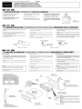
BEFORE STARTING I PR P
-1.
a
1. This set is exclusively for use in cars with a
negative ground, 12 V power supply.
12 V
2. Read these instructions carefully.
3. Be sure to disconnect the battery" 8 " terminal before starting. This is to prevent short circuits during installation (Figure 1).
IFS I ANTES DE COMENZAR
a
est exclusivement destine etre
les voitures avec une aHnlentation
rnasse negative.
1. Esta unidad ha sido disenada para utilizarse
exclusivamente en autom6viles con fuente de
alimentaci6n de 12 V, Y negativo amasa.
2. Lire ces instructions attentivement
2. Lea cuidadosamente estas instrucciones.
3. S'assurer de debrancher la borne H E) II de la
batterie avant de commencer. Cela evitera les
court-circuits pendant nnsta!latlon (Figure i).
3. Antes de comenzar, cerci6rese de desconectar el terminal" 8 " de la baterfa. Esto es para
evitar cortocircuitos durante la instalaci6n
(Figura 1).
Car battery
Batterle de voiture
Baterfa del autom6vil
Figure 1 / Figure 1 I Figura 1
-2. CAUTIONS ON INSTALLATION I P EC
UTI
1. Prepare all articles necessary for installing the source unit before
starting.
1. Avant de f"'r.;mn"or"'lf"e;:::IY
pour installer
2. Install the unit within 30° of the horizontal plane (Figure 2).
2. Installer rapparei! avec un angle inferieur
rlzontal (Figure 2).
3. If you have to do any work on the car body, such as drilling holes,
consult your car dealer beforehand.
I PRECAUCIONES PARA LA INSTALACION
U SUJET DE I!I STALL
toutes les pieces necessaires
1. Antes de comenzar, prepare todos los elementos necesarios para
instalar la unidad fuente.
a 30° par rapport a rho-
2. Instale la unidad con un angulo de 30° sobre el plano horizontal
(Figura 2).
3. S'j1 est necessaire dleffectuer certains travaux sur !a carrosserie
comme
des trous, consulter d'abord votre concessionnaire
3. Si tiene que realizar cualquier trabajo en la carrocerfa, como taladrado de orificios, etc., consulte al proveedor de su autom6vil.
4. Use the enclQsed screws for installation. Using other screws can
cause damage (Figure 3).
4. Utillser les vis fournies pour l'installation. L'utllisation d'autres vis
peut causer des dommages (Figure 3).
4. Utilice los tornillos suministrados para la instalaci6n. La utilizaci6n
de otros tornillos podrfa resultar en danos (Figura 3).
Chassis / ChassIs I Chasis
Chassis / Chassis I Chasis
Max. 30°
Max. 30°
Max. 30°
r
~
I
Max. 5/16" (8 mm)
Max. 5/16'1 (8 mm)
Max. 5/16" (8 mm)
:
Damage
Endommage
Dafiado
Figure 3 / Figure 3 / Figura 3
Figure 2 I figure 2 I Figura 2
'nd'
-3.
•
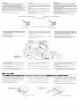
INSTALLING THE SOURCE UNIT II 51 L
Universal Mount
•
1. Place the universal mounting bracket into the instrument panel,
use a screwdriver to bend each stopper of the universal mounting
bracket inward, then secure the stopper as shown in Figure 4.
E l'A PRElL Pil TE IINSTALACION DE LA UNlOAD FUENTE
•
Montage universel
Montaje universal
1. Placer Ie support de
universel dans Ie tableau de bord,
utiliser un tournevis pour
vers l'exterieur chaque lanqU€3Ue
du
de
universel, puis fixer les languettes
sur la Figure
1. Coloque el soporte de montaje universal en el tablero de instrumentos, utilice un destornillador para doblar cada reten del
soporte de montaje universal hacia adentro, y despues asegure
el reten como se muestra en la Figura 4.
2. Cabler comnle nlontre dans la Section 8.
2. Conecte los cables como se muestra en la Secci6n 8.
2. Wire as shown in Section 8.
3. Insert the source unit into the universal mounting bracket until it
locks.
dans Ie support de montage universe!
bloque.
3. Inserte la unidad fuente en el soporte de montaje universal hasta
que quede enganchado.
f\~onter recusson exterieur de maniere que tous les crochets
solent verrouilles.
4. Inserte la pieza ornamental exterior en el soporte de montaje universal hasta que quede enganchado.
4. Mount the outer escutcheon so that all the hooks are locked.
4.
Notes:
1) Some car models require special mounting kits for proper
installation. Consult your Clarion dealer for details.
2) Fasten the front stopper securely to prevent the source unit
from coming loose.
1) Certains modeles de voiture necessitent un kit de nl0ntage
pour une installation correcte. Consulter !e revendeur
pour les details.
Notas:
1) Algunos modelos de autom6viles requieren juegos de montaje
especiales para realizar la instalaci6n apropiada. Solicite los
detalles a su proveedor Clarion.
2) Serrer fermenlent la languette avant pour eviter que lfappareil
pilote ne se desserre.
2) Apriete con seguridad el reten frontal para evitar que se afloje
la unidad fuente.
Remarques:
• Console opening dimensions
Dimensions d'ouverture de la
• Dimensiones de la abertura de
@l
Hole
Trou
Orificio
i
lnstrument panel
Tableau de bord
Tablero de instrumentos
66
66
6
.r----
Stoppers
Languettes
Retenes
///~
Hexagonal bolt
Ecrou hexagonal
Perno hexagonal
Strap
Armature
Banda
This part is not provided in some models.
* Cette piece n'existe pas sur tous les modeles.
* Esta pieza no se suministra con algunos modelos.
*
J
Top
Haut
Parte superior
Screwdriver
Tournevis
Destornillador
t
~
~
Source Unit
Appareil pilote
Unidad fuente
Universal mounting bracket
Support de montage universel
Soporte de montaje universal
Note:
Installation direction
Sens d'installation
Direcci6n de instalaci6n
Stoppers
Languettes
Retenes
Before attaching the universal mounting bracket, slightly bend
the spring toward the inside with your fingers and attach it to the
side of car.
Remarque:
Avant de fixer Ie patin de
ressort vers l'interieur avec
voiture.
Nota:
Bottom
Bas
Parte inferior
Outer escutcheon side view
Vue laterale de recusson exterieur
Vista lateral de la pieza ornamental exterior
Outer escutcheon
Ecusson exterieur
Pieza ornamental exterior
Antes de fijar el soporte de montaje universal, doble ligeramente
el resorte hacia el interior con los dedos y ffjelo en la parte lateral
del autom6vil.
Figure 4/ Figure 4 I Figura 4
•
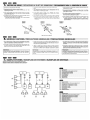
Fixed Mount
(TOYOTA, NISSAN and other ISO/DIN equipped vehicles)
•
MO:flt::lge fixe
NISSAN et 8utres vehicules
This unit is designed for fixed installation in the dashboard.
If the vehicle is equipped with a factory-installed radio, install the
source unit with the parts and screws marked (*) (Figure 7).
If the vehicle is not equipped with a factory-installed radio, obtain an
installation kit to install the source unit in the following procedure.
ISO/DIN)
une installation fixe dans Ie tableau de
d'un auto-radio installe l'usine
pieces et les ecrous marquees de
a
j
d'un auto-radio installe a I'usine se
d'irlstallclticm pur installer l'appareil pilote avec la
Bend the stopper following the procedures below when this source
unit is installed to the TOYOTA, NISSAN and other ISO/DIN equipped
vehicles.
ci-dessous
TOYOTA,
Montaje fijo
(Automoviles TOYOTA, NISSAN, Yotros provistos de normas ISO/DIN)
Esta unidad ha sido disenada para instalarse de forma fija en el
tablero de instrumentos. Si el autom6vil dispone de una radio instal
ada en fabrica, instale la unidad fuente con las piezas y los tornillos
marcados con (*) en la Figura 7.
Si el autom6vil no dispone de una radio instalada en fabrica, adquiera
un juego de instalaci6n para instalar la unidad fuente de acuerdo con
el procedimiento siguiente.
Doble de instalar esta unidad en vehfculos TOYOTA, NISSAN, Y
otoros equipados con ISO/DIN, extraiga el reten siguiendo los procedimientos indicados a continuaci6n.
ill""\£:':l.I'!':)tIAI'''IC'
1. Bend the stopper from the source unit. (Figure 5, 6)
1. Coubez !a butee de rapparei! source. (Figure 5, 6)
1. Doble el reten procedente de la unidad fuente. (Figura 5, 6)
AFTER BEND/APRES LA COURBUREIDESPUES DE DOBLAR
BEFORE BEND/AVANT LA COURBUREIANTES DE DOBLAR
STOPPERITOURNEV1S/OESTORNILLAOOR
SOURCE UNIT/APPARE!L PILOTE/UNlOAD FUENTE
Figure 5/Figure 5/Figura 5
2. Secure the mounting brackets to the chassis as shown in Figure
7. Holes are pre-tapped for TOYOTA and NISSAN vehicles; modification, such as drilling new holes, of the mounting brackets may
be required for other models.
2.
Figure 6/Figure 6/Figura 6
de montEtqe sur Ie chassis CO!llme montre sur la
trous sont
pour les vehicules TOYOTA
l\ll;:')~}~l\l: des modification du
de
comme Ie
de nouveaux trous,
etre
pour les
modeles.
2. Asegure los soportes de montaje al chasis como se muestra en
la Figura 7. Los orificios ya han sido taladrados en los
autom6viles TOYOTA y NISSAN, pero para otros modelos puede
resultar necesario realizar modificaciones, como taladrado de
nuevos orificios en los soportes de montaje.
3. Wire as shown in Section 8.
3. Cabler comrne
4. Secure the unit in the dashboard, and then reassemble the dashboard and the center panel.
4.
montH~
dans la Section 8.
3. Conecte los cables como se muestra en la Secci6n 8.
dans Ie tableau de bord puis remonter Ie tableau
panneau centraL
4. Asegure la unidad al tablero de instrumentos, y despues vuelva a
montar el tablero de instrumentos y el panel central.
*
Mounting bracket
(1 pair for the left and right sides)
:J<
Support de
(1 paire, pour
gauche et droite)
Soporte de montaje
(1 par para los lados izquierdo y derecho)
*
Center Panel (Note 1)
Panneau central (Remarqure 1)
Panel central (Nota 1)
*
Figure 7 / Figure 7 / Figura 7
et les vis portant cette
sont utilisees pour I'aulnstalle au fournies dans Ie kit d'Hlsta!l,3.tl()n
Les vis portant cette marque sont fournies d'orlgine avec Ie
vehicu!e.
*: The parts and screws with this mark are used to install radio or
included in the installation kit.
The screws with this mark are originally attached to the vehicle.
*:
Note 1: In some cases, the center panel may require some modifi-
Remarque 2: Dans certains cas, Ie panneau central peut necessite
*:
certaines modifications (ebarbage, rernpllssage, etc.).
cation (trimming, filling, etc.).
Note 2: If a hook on the installation bracket interferes with the unit,
*: Las piezas y tornillos con esta marca se utilizan para instalar la
radio 0 se suministran con el juego de instalaci6n.
Los tornillos con esta marca estan original mente fijados a los
autom6viles.
*:
Nota 1: En algunos casos, el panel central puede requerir ciertas
modificaciones (recorte, Iimado, etc.).
Remarque 2: 5i un crochet du support d'installation interfere avec
Nota 2: Si algun gancho del soporte de montaje interfiere con la unidad,
!e tardre et l'ap!atir avec une pince au un outil
d6blelo y aplanelo con unos alicates u otra herramienta similar.
bend and flatten it with a nipper or a similar tool.
e,;',(,'·
-4.
REMOVAL OF THE SOURCE UNIT I
I DESMONTAJE DE LA UNlOAD FUENTE
1. When removing the source unit, disassemble it in the reverse of
the order in Section "3. INSTALLING THE SOURCE UNIT".
i. Lors de la
2. Press the outer escutcheon upward and remove it (Figure 8).
2. Presser l'ecusson exterieur vers Ie haut et Ie retirer (Figure 8).
3. Insert and lock the hook plates (Figure 9).
3. Inserer et verrouiller les plaques
4. Pull the hook plates to remove the source unit.
4. Tirer sur les plaques
demonter dans rordre inverse
PILOTE".
de la Section
a crochet (Figure 9).
a crochet pour retirer !'appareil pilote.
1. Para desmontar la unidad fuente, r,ealice el procedimiento inverso al de la Secci6n "3. INSTALACION DE LA UNlOAD FUENTE".
2. Presione la pieza ornamental exterior hacia afuera y extraigala
(Figura 8).
3. Inserte y bloquee las placas de enganche (Figura 9).
4. Tire de las placas de enganche para extraer la unidad fuente.
2-Hook plates - - - - , .
2-Plaques crochet
2-Placas de enganche
Outer escutcheon
Ecusson exterieur
Pieza ornamental exterior
a
Figure 8/ Figure 8/ Figura 8
Figure 9 / Figure 9 / Figura 9
-5
GAUIIONS ON WIRING I PREG UIIO S AU SUJEI DES 0 NEXIONS I PREGAUGIONES PARA LA GONEXION DE CABLES
n
1. Be sure to turn the power off when wiring.
1. S'assurer de meitre l'apparel! hors circuit avant de faire Ie ca
2. Be particularly careful where you route the wires.
Keep them well away from the engine, exhaust pipe, etc. Heat
may damage the wires.
2.
3. If the fuse should blow, check that the wiring is correct.
If it is, replace the fuse with a new one with the same amperage
rating as the original one.
3. Si
5i
4. To replace the fuse, open the lock on the source unit side, remove
the old fuse and insert the new one. (Figure 10)
* There are various types of fuse cases. Do not let the battery
side terminal touch other metal parts.
4.
1. Antes de hacer las conexiones, asegurese de desconectar la alimentaci6n de la unidad.
oartic:ulierE)mlsnt attention lars de I'acheminement des fils.
moteur, des
d'echappement, etc. La
d'end()mllla~Qerces
2. Sea especial mente cuidadoso al dirigir y fijar los cables.
mantengalos alejados del motor, tubo de escape, etc. EI calor
puede danar los cables.
verifier si Ie cablage est correct.
remplacer par un fusible neuf de meme
d'origine.
3. Si el fusible se quema, revise las conexiones.
Si esta quemado, reemplace el fusible por otro nuevo con el
mismo valor de amperaje que el original.
loquet sur Ie cote
et
Ie fusible neuf.
de boTtiers fusibles. Ne pas
en contact avec les autres pieces
4. Para reemplazar el fusible, abra la tapa de la unidad fuente, retire
el fusible antiguo e instale otro nuevo. (Figura 10)
* Existen distintos tipos de cajas de fusibles. no permita que el
terminal del lado de la baterfa quede en contacto con otras
partes metalicas.
a
Example 1
Exemple 1
Ejemplo 1
Example 3
Exemple 3
Ejemplo3
Example 2
Exemple 2
Ejemplo 2
Fuse case
Boltier fusible
Caja de fusible
a
Fuse case
Boltier a fusible
Caja de fusible
Figure 10 I Figure10 I Figura 10
'#liM' 4'6'hll •.n",."
-6.
GENERAL CAUTIONS I PRECAUTIONS GENERALES I PRECAUCIONES GENERALES
1. Do not open the case. There are no user serviceable parts inside.
If you drop anything into the unit during installation, consult your
dealer or an authorized CLARION service center.
2. Use a soft, dry cloth to clean the case. Never use hard cloth, thinner, benzen, alcohol, etc. For tough dirt, apply a little cold or warm
water to a soft cloth and wipe off the dirt gentry.
IMPORTANT:
Improper installation may cause damage to your unit or car. If you
do not have the appropriate experience, consult a qualified
installer. Cutting chassis wire leads voids the warranty.
••
-7
n
1. Ne pas ouvrir Ie coftret. II n'y a pas de pieces reparables par l'utilisateur I'interieur de I'appareil. Si un objet est tombe dans l'appendant I'installation, consulter votre revendeur ou un serapres-vente agree CLARION.
1. No abra la caja. En el interior no hay piezas que pueda reparar el
usuario. Si dentro de la unidad entra algo durante la instalaci6n,
consulte a su proveedor 0 a un centro de servicio autorizado por
CLARION.
2. Utiliser un chiffon doux et sec pour nettoyer Ie coffret, ne jamais
2. Para limpiar la caja, utilice un pano suave y seco. no use nunca
un pano duro, diluidor de pintura, benceno, alcohol, etc. Para la
suciedad resistente, aplique un poco de agua frfa 0 caliente a un
pano suave y frote suavemente la parte sucia.
a
utiliser un chiffon rigide, un diluant, du benzene, de I'alcool, etc.
Pour enlever la salete tenace, appliquer un peu d'eau froide ou
tiede sur un chiffon doux et essuyer doucement la salete.
IMPORTANT:
Une installation incorrecte peut endommager rappareil au Ie
vehicule. Si !'on ne possede pas les connaissances requises, consulter un installateur qualifie. Couper Ie fil du chassis annule la
garantie.
IMPORTANTE:
La instalaci6n inapropiada puede causar danos en su unidad 0 su
autom6vil. Si usted no posee la experiencia apropiada, consulte a
un instalador cualificado. EI corte de los conductores de puesta a
masa (carrocerfa) anulara la garantfa.
fIR,
SAMPLE SYSTEMS I EXEMPL S DE SYST MES I EJEMPLOS DE SISTEMAS
• Example of the system using an external amplifier (Audio Visual)
III Exemple de systeme utmsant un amplificateuf exterieur. (audi(FVisuel)
• Ejemplo de sistema utilizando un amplificador externo (audiovisual)
.11
CD
®
@
@
®
®
®
®
Source Unit
RCA Extension Cables (sold separately)
2-Channel Power Amplifier
4-Channel Power Amplifier
Front Speakers
Rear Speakers
Sub-woofers
External unit
CD Appareil pilote
· · · ·&5·· · ····C€1hi·e·s···p·ro·i·o·n~iaie·lJ"r····R·(j"A····(·v·e·n'au"'s-~i)"a'r~'me'nty"
@
@
(§)
®
®
...®
Amplificateur de puissance 2 canaux
Amplificateur de puissance 4 canaux
Haut-parleurs avant
Haut...parleurs arriere
Sub-woofers
Aiipare"i"f'externe
.·kI",'·
CD
®
®
®
®
@
®
®
®
®
Unidad fuente
Cables prolongadores RCA (vendidos aparte)
Amplificador de potencia de 2 canales
Amplificador de potencia de 4 canales
Altavoces delanteros
Altavoces traseros
Altavoces de subgraves
Unidad externo
'w®.
-8.
••$1
,i.'.
WIRE CONNECTIONS I CONNECTIQUE I CONEXION DE CABLES
• Rear Layout
III Disposition arriere
• Disposici6n trasera
No.
Description
CD
®
AUX INPUT RIGHT (Red)
AUX INPUT LEFT (White)
®
FRONT RIGHT (Red)
@
FRONT LEFT (White)
®
®
No.
CD
Description
No.
Description
ENTREE AUX droite (Rouge)
CD
Entrada auxiliar (AUX INPUT) del canal derecho (Rojo)
®
ENTREE AUX gauche (Blanc)
AVANT DROIT (Rouge)
®
®
Entrada auxiliar (AUX INPUT) del canal izquierdo (Blanco)
@)
(1]
AVANT GAUCHE (Blanc)
@
DELANTERO IZQUIERDA (Blanco)
REAR RIGHT (Red)
@)
ARRIERE DROIT (Rouge)
TRASERO DERECHO (Rojo)
REAR LEFT (White)
®
ARRIERE GAUCHE (Blanc)
®
®
Antenna
Antenne
Antena
CD
®
®
@
DELANTERO DERECHO (Rojo)
TRASERO IZQUIERDA (Blanco)
®
16-pin connector
Connecteur 16 broches
Conector de 16 contactos
l--
16-Pin Connector Extension Lead
(attached to the source unit)
FiJ prolongateur-connecteur 16 broches
~(attache sur I'appareil pilote)
Cable prolongador de 16 contactos
+ Grey
(fijado a la unidad fuente)
+ Gris
+ Gris
Front Right
Avant droit
Delantero derecho
- Grey/Black
- Gris/noir
- Gris/negro
+ White
+ Blanc
+ Blanco
Orange/White wire (Illumination lead)
Fil orange/blanc (fil d'eclairage)
Conductor anaranjado/blanco (conductor de alimentaci6n)
Front Left
Avant gauche
Delantero izquierdo
4-Speaker system
Systeme a 4 haul-parJeurs
Sistema con 4 altavoces
+ Purple
+ Pourpre
+ Purpura
- White/Black
- Blanc/noir
- Blanco/negro
Yellow wire (Memory back-up lead)
Fil jaune (fil de soutien memoire)
Conductor amarillo (Conductor ~e protecci6n de la memoria)
Rear Right
Arriere droit
Trasero derecho
- Purple/Black
- Pourpre/noir
- Purpura/negro
+ Green
+ Vert
+ Verde
Rear Left
Arriere gauche
Trasero izquierdo
Connect directly to battery.
Brancher directement la baUerie.
Conectelo directamente a la baterfa.
a
Fuse (15 A)
Fusible (15 A)
Fusible (15 A)
- Green/Black
- Vert/noir
- Verde/negro
or
Red wire (Power lead)
Fil rouge (til d'alimentation)
Conductor rojo (Conductor de alimentaci6n)
o
+ Grey
+ Gris
+ Gris
Accessory + 12 V
Accessoire + 12 V
Accesorio +12 V
Right
Droit
Derecho
- Grey/Black
- Gris/noir
- Gris/negro
+ White
+ Blanc
+ Blanco
Left
Gauche
Izquierdo
2-Speaker system
Systeme :2 haut-parleurs
Sistema con 2 altavoces
a
+ Purple
+ Pourpre
+ Purpura
- Purple/Black
- Pourpre/noir
- Purpura/negro
Not used.
Insulate each wire.
Inutilise.
Isoler chaque fil.
No se utiliza.
Aisle todos los conductores.
Blue/White wire (Power Antenna turn-on lead)
Fil bleu/blanc (fil de mise sous tension d1antenne electrique)
Conductor azul/blanco (Conductor de conexi6n de la alimentaci6n de la antena motorizada)
Connect to remote turn-on lead of Power Antenna. (0.5 A current max.)
Connectez Ie til de mise sous tension tEdecommandable de I'antenne
electrique. (Courrant maximum de 0,5 A)
Conectelo al conductor de conexi6n automatica de la alimentaci6n de la
antena motorizada. (corriente maxima de 0,5 A)
- White/Black
- Blanc/noir
- Blanco/negro
+ Green
+ Vert
+ Verde
- Green/Black
- Vert/nair
- Verde/negro
Black wire (Ground lead)
Fil noir (til de terre)
Conductor negro (Conductor de puesta amasa)
Connect to vehicle chassis ground.
Brancher la terre du chassis du vehicule.
Conectelo a una parte metalica del chasis del vehfculo.
a
Clarion Co., Ltd.
281-0632-00 2005/9
CLARION 2006 LIMITED WARRANTY
For USA and Canada only
Except as noted, Clarion products purchased from an authorized Clarion dealer are warranted against all defects in
materials and workmanship for a period of one (1) year from the date of original purchase.
The following Clarion products noted below ** are warranted against all defects in materials and workmanship for a two
(2) year period from the date of original purchase when purchased from AND installed by an authorized Clarion dealer.
** DRZ9255 DXZ865MP D~Z765MP DXZ665MP DXZ465MP DFZ675MC DPX11500 DPX1800 DPX2250
All Clarion cables, wires and other accessories if purchased from an authorized Clarion dealer are warranted against
all defects in materials and workmanship for ninety (90) days from the date of original purchase,
ALL PURCHASES OF CLARION PRODUCTS FROM NON-AUTHORIZED CLARION DEALERS ARE SUBJECT
TO FURTHER WARRANTY RESTRICTIONS AS DESCRIBED BELOW.
The conditions of this Limited Warranty and the extent of responsibility of Clarion Corporation of America ("Clarion n )
under this Limited Warranty are as follows:
1. PROOF OF DATE OF PURCHASE FROM AN AUTHORIZED CLARION DEALER WILL BE REQUIRED FOR
WARRANTY SERVICE OF THIS PRODUCT. IN THE CASE OF THE TWO (2) YEAR LIMITED WARRANTY FOR THE
CLARION PRODUCTS NOTED ABOVE, PROOF OF DATE OF PURCHASE AND PROOF OF INSTALLATION BY AN
AUTHORIZED CLARION DEALER IS REQUIRED. INFORMATION ABOUT CLARION AUTHORIZED WARRANTY
SERVICE CENTERS MAY BE OBTAINED BY CONTACTING CLARION AT THE ADDRESS LISTED BELOW.
2. This Limited Warranty will become void if service performed by anyone other than an approved Clarion Warranty
Service Center results in damage to the products.
3. This Limited Warranty does not apply to any product which has been subject to misuse, neglect or accident,
or which has had the serial number altered, defaced or removed, or which has been connected, installed,
adjusted or repaired, other than in accordance with the instructions furnished by Clarion.
4, This Limited Warranty does not cover car static or other electrical interferences, tape head or laser pick-up
cleaning or adjustments, or labor costs for the removal or reinstallation of the unit for repair.
5. The sole responsibility of Clarion under this Limited Warranty shall be limited to the repair of the products or
replacement of the product, at the sole discretion of Clarion.
6. Product must be shipped in its original carton or equivalent carton, fully insured with shipping charges prepaid.
j
Clarion will not assume any responsibility for any loss or damage incurred in shipping.
7. CLARION PRODUCTS PURCHASED FROM A SOURCE OTHER THAN AN AUTHORIZED CLARION DEALER,
INCLUDING ANY AND ALL PURCHASES VIA THE INTERNET FROM A NON INTERNET AUTHORIZED
CLARION DEALER, SHALL NOT BE COVERED BY ANY CLARION LIMITED WARRANTY TO THE EXTENT
ALLOWED BY APPLICABLE LAW. IN THE EVENT AND TO THE EXTENT APPLICABLE LAW PROHIBITS
ELIMINATION OF WARRANTIES UNDER THESE CIRCUMSTANCES, THE APPLICABLE LIMITED WARRANTY
PERIOD SHALL BE DEEMED TO BE FIFTEEN (15) DAYS FROM THE DATE OF ORIGINAL PURCHASE.
8. ALL IMPLIED WARRANTIES EXCEPT TO THE EXTENT PROHIBITED BY APPLICABLE LAW SHALL HAVE NO
GREATER DURATION THAN THE WARRANTY PERIOD SET FORTH ABOVE. UNDER NO CIRCUMSTANCES
SHALL CLARION BE LIABLE FOR ANY LOSS OR DAMAGE, DIRECT OR CONSEQUENTIAL, ARISING OUT
OF THE USE OR INABILITY TO USE THE PRODUCT. BECAUSE SOME STATES 00 NOT ALLOW LIMITATIONS
ON HOW LONG AN IMPLIED WARRANTY LASTS OR EXCLUSIONS OR LIMITATIONS OF INCIDENTAL OR
CONSEQUENTIAL DAMAGES, THE ABOVE LIMITATIONS OR EXCLUSIONS MAY NOT APPLY TO YOU.
9. THIS LIMITED WARRANTY GIVES YOU SPECIFIC LEGAL RIGHTS, AND YOU MAY ALSO HAVE OTHER RIGHTS
WHICH VARY FROM STATE TO STATE.
10. The laws of the State of California shall govern and control this limited warranty, its interpretation and enforcement.
11. Should you have any difficulties with the performance of this product during the warranty period, please call Clarion
or visit our web site for a listing of Authorized Warranty Service Centers in your area, You may also contact the
Clarion Customer Service at the address listed below for any service help you may need with Clarion products.
In USA:
Clarion Corporation of America
Attn:Customer Service Manager
661 W. Redondo Beach Blvd
Gardena, CA.90247..4201
1-800..GO-CLARION
www.clarion.com
In Canada:
Clarion Canada Inc,
Warranty Service Center
2239 Winston Park Drive
Oakville, Ontario L6H 5R 1
(905) 829-4600
www.clarioncanada.com