1
Owner's manual
Mode d'emploi
Manual de instrucciones
CZI09
CD/MP3IWMA RECEIVER
AUTORADIO CD/MP3IWMA
RECEPTOR CD/MP3IWMA
CLARION PRODUCT REGISTRATION INFORMATION
For USA and Canada only
www.clarion.com
Dear Customer:
Congratulations on your purchase of a Clarion mobile electronic products. We are confident
that you'll enjoy your Clarion experience.
There are many benefits to registering your product. We invite you to visit our website at
www.clarion.com to register your Clarion product.
We have made product registration simple with our easy to use website. The registration form
is short and easy to complete. Once you're registered, we can keep you informed of important
product information.
Register at www.clarion.com - it's easy to keep your Clarion product up to date.
INFORMATIONS DE L'ENREGISTREMENT DE PRODUITS CLARION
Pour les Etas Unis et Ie Canada seulement
www.clarion.com
Cher client:
Nous vous remercions d'avoir achete ce produit electronique mobile Clarion. Nous sommes
confiants que vous apprecierez votre experience Clarion.
II y a beaucoup d'avantage a enregistrer votre produits. Nous vous invitons
Web www.clarion.com pour enregistrer votre produit Clarion.
a visiter notre site
a
Nous avons facilite la tache d'enregistrement de produit simple et facile grace notre site Web.
Le formulaire d'enregistrement est court et facile a completer. Lorsque vous etes enregistrer,
nous pouvons vous tenir informe des informations important de produits.
Enregistrer
a www.clarion.com - c'est facile de mettre a jour votre produit Clarion.
INFORMACION DEL REGISTRO DE PRODUCT 0 DE CLARION
Para USA Y Canada nomas
www.clarion.com
Querido Cliente:
Felicitaciones por su compra de producto electr6nico m6vil de Clarion. Estamos seguros que
usted gozara de su experiencia con el producto de Clarion.
Hay muchas ventajas al registrar su producto. Le invitamos a que visite nuestro sitio en internet
www.clarion.com para registrar su producto de Clarion.
Hemos hecho el registro de producto facil en nuestro sitio. La forma de registro es corta y facil
de completar. Una vez que 10 registre, podremos proporcionarle la informaci6n de su producto.
Registrese en www.clarion.com - es facil mantener su producto de Clarion actualizado.
2
CZ109
Thank you for purchasing this Clarion product.
*
*
Please fully read this owner's manual before operating this equipment.
Check the contents of the enclosed warranty card and store it in a safe place with this manual.
Contents
1. FEATURES
2. PRECAUTIONS
3. CONTROLS
3
4
5
Names of the Buttons and Their Main Functions
5
4. DCP (DETACHABLE CONTROL PANEL)
5. REMOTE CONTROL
6
7
Functions of Remote Control Unit Buttons
inserting the Battery
7
8
8
8
6. OPERATIONS
Basic Operations
Radio Operations
CO/MP3IWMA Operations
Operations Common to Each Mode
10
11
14
7. TROUBLESHOOTING
8. ERROR DISPLAYS
9. SPECIFICATIONS
16
17
18
1. FEATURES
(illD~~
plGITALAUPID
TEXT
I
H1"~
ID3TAG
_ . Plays
•
_TM ----'Wln-dows----i
MediaN
'..,
• Built-in IR Eye (RCB176 Remote Included)
• 4ch/2V RCA Output with Non Fader Volume Control
• Front Panel 3.5mm Auxiliary Input
CZ109
3
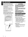
2. PRECAUTIONS
This equipment has been tested and found to
comply with the limits for a Class B digital
device, pursuant to Part 15 of the FCC Rules.
These limits are designed to provide reasonable
protection against harmful interference in a
residential installation.
This equipment generates, uses, and can
radiate radio frequency energy and, if not
installed and used in accordance with the
instructions, may cause harmful interference to
radio communications. However, there is no
guarantee that interference will not occur in a
particular installation.
If this equipment does cause harmful
interference to radio reception, which can be
determined by turning the equipment off and on,
the user is encouraged to consult the dealer or
an experienced radio technician for help.
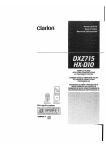
MOOEL
I
I clarion
12V 8 GROUND
AM 530-1710kHz/FM 87.9-107.9MHz
THIS DEVICE COMPLIES WITH PART 15 OF THE FCC RULES.
OPERATION IS SUBJECT TO THE FOLLOWING TWO CONDITIONS:
(1) THIS DEVICE MAY NOT CAUSE HARMFUL INTERFERENCE. AND
(2) THIS DEVICE MUST ACCEPT ANY INTERFERENCE RECEIVED,
INCLUDING INTERFERENCE THAT MAY CAUSE UNDESIRED
OPERATION.
THIS PRODUCTION COMPLIES WITH DHHS RULES 21 CFR
SUBCHAPTER J APPLICABLE AT DATE OF MANUFACTURE.
CLARION CO.• LTO
7-2. SHINTOSHIN,CHUO-KU,SAITAMA-i¥iI.SAITAMA 330-0081.JAPAN
This product includes technology owned by
Microsoft Corporation and cannot be used or distributed
without a license from MSLGP.
MANUFACTURED:
SERIAL No.
PE-c::::::J
4
CZ109
tf?\
~
278c::::::J
Clarion Co., Ltd.
MADE INc::::::::J
>'1'"
.[r:At"AutIOH>
.,
USE OF CONTROLS, ADJUSTMENTS, OR
PERFORMANCE OF PROCEDURES OTHER
THAN THOSE SPECIFIED HEREIN, MAY
RESULT IN HAZARDOUS RADIATION
EXPOSURE.
THE COMPACT DISC PLAYER SHOULD NOT
BE ADJUSTED OR REPAIRED BY ANYONE
EXCEPT PROPERLY QUALIFIED SERVICE
PERSONNEL.
CHANGES OR MODIFICATIONS NOT
EXPRESSLY APPROVED BY THE
MANUFACTURER FOR COMPLIANCE
COULD VOID THE USER'S AUTHORITY TO
OPERATE THE EQUIPMENT.
INFORMATION FOR USERS:
CHANGES OR MODIFICATIONS TO THIS
PRODUCT UNAPPROVED BY THE
MANUFACTURER WILL VOID THE
WARRANTY AND VIOLATE FCC APPROVAL.
Handling Compact Discs
• Compared to ordinary music CDs, CD-R and
CD-RW discs are easily affected by high
temperatures and humidity, potentially
making them unplayable. Therefore, do not to
leave them in the car for a long time.
• Do not stick labels on compact discs or mark
the surface with pens or pencils.
Display Screen
• In extreme cold, the screen movement may
slow down and the screen may darken, but
this is normal.
The screen will recover when it returns to
normal temperature.
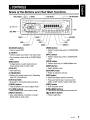
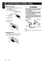
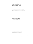
3. CONTROLS
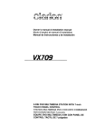
Names of the Buttons and Their Main Functions
~-- [IR RECEIVER]
[~]
(EJECT) -....;-...c:....,::..
[~], [~]--=-....:.:..-...
[ISR]---J
[ROTARY]
[RELEASE] button
[ROM] button
• Press to unlock OCP.
• Perform random play while in CO/MP3IWMA
mode.
[~~I~] button
• Perform preset scan while in the radio mode.
• Play or pause a track while in CO/MP3IWMA
mode.
[RPn button
• Perform repeat play while in CO/MP3IWMA
mode.
[BND] button
[SCN] button
• Change bands, or select seek tuning or
manual tuning while in radio mode.
• Perform scan play in CO/MP3IWMA mode.
[CD SLOn
• Switch display mode.
[DISP] button
• Insert COs here.
[ROTARY] knob
[IR RECEIVER]
• Rotate to adjust the volume.
• Receiver for remote control unit. (Operating
range: 30° all directions)
[ISR] button
[AUX] input jack
• Recall ISR station stored in memory.
• Input jack for connecting external device.
• Press and hold (2 sec.) to store current
station in ISR memory (radio mode only).
[SOUND] button
[SRC] button
• Press to switch to the sound adjust mode.
• Turn the power on/off.
[UP], [ON] buttons
• Select folders while in MP3IWMA mode.
[~], [~] buttons
• Commence fast-forward/fast-reverse mode.
[DIRECn buttons
[~] (EJECT) button
• Store radio stations in memory or recall it
directly while in radio mode.
• Press to eject disc.
CZ109
5
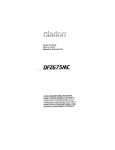
4. DCP (DETACHABLE CONTROL PANEL)
Removing the DCP
1. Press and hold the [SRC] button (1 sec.) to
switch off power.
2. Press the [RELEASE] button.
~ [RELEASE) button
~
I
• After removal, be careful not to drop the
DCP or subject it to strong impacts, to
prevent damage.
• Once the [RELEASE] button is pressed
and the DCP is unlocked, car vibrations
can cause the DCP to fall.
• The connector for the main unit and DCP
is extremely important. Be careful not to
damage it by pressing with fingernails or
sharp objects.
Main Unit Front
* OCP is unlocked.
3. Remove OCP.
DCP
connector
Note:
• If the DCP is dirty, wipe off with a soft, dry cloth
only.
Attaching the DCP
1. Insert the right end of OCP into main unit.
2. Press left end of OCP into main unit.
6
CZ109
• Radio mode
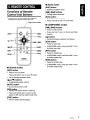
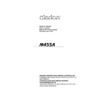
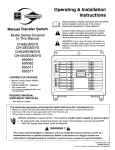
5. REMOTE CONTROL
[BND] button
• Switches reception band.
Functions of Remote
Control Unit Buttons
r
[1+1I], [~] buttons
• Change preset channels.
[SCN] button
* Some buttons on the remote have different
• Press for preset scan play.
functions from those on the main unit.
• Press and hold (2 sec.) for auto store.
Signal transmitter
• CDIMP3/WMA modes
[1+1I], [~] buttons
• Press to select tracks.
~::::=:'K=====::::-~.~
---+1 Q
11
[SRC]
+1
A
I
~ i
[!], [,]
[MUTE]
IIII ~~ G:) G
MUTE./ ISR
[JSR]---f~il
8
[SCN]
[BND]
.............. .;....--- [ ~ II ]
OISP
II
I
[I+il).
["'1
[DISP]
Q Q'---Hi--- [ROM]
II
'\.-..;.;;TV,.;.;;;.VTR----H_ _ [RPT]
RP~
seN
"'A'
RDM
Clarion
• Press and hold (1 sec.) for fast-forward/fastreverse.
[~II] button
• Switches between playback and pause.
[SCN] button
• Press for scan play.
• In MP3IWMA mode, press and hold (1 sec.)
for folder scan play.
[RPT] button
• Press for repeat play.
• In MP3IWMA mode, press and hold (1 sec.)
for folder repeat play.
[ROM] button
• Press for random play.
• Shared modes
• In MP3IWMA mode, press and hold (1 sec.)
for folder random play.
[SRC] button
• Press to turn on power.
Press and hold (1 sec.) to turn off power.
• Use to change operation mode.
[.], [T] buttons
• Increases/decreases volume.
[MUTE] button
• Turns mute function on/off.
[ISR] button
• Recalls ISR station stored in memory.
• Press and hold (2 sec.) to store current
station in ISR memory (radio mode only).
[DISP] button
• Press to select desired display.
CZ109
7
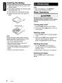
Inserting the Battery
CD
Slide remote control unit's rear cover in the
direction shown.
®
Insert battery (CR2025) into insertion guides
with printed side (+) up.
® Press battery into compartment as shown.
@ Replace and slide cover until it clicks into
place.
6. OPERATIONS
Note:
• Refer to the diagrams in "3. CONTROLS"
(page 5) when reading this chapter.
Basic Operations
Be sure to lower the volume before
switching off the unit power or car's ignition
key. The unit remembers its last volume
setting.
Turning power on/off
Insertion guide
1. Press the [SRC] button to turn on power.
2. Press and hold the [SRC] button (1 sec.) to
turn off power.
Selecting modes
Notes:
Misuse may result in battery rupture and fluid
leakage, resulting in personal injury or damage.
Always follow these safety precautions:
• Use only the designated battery.
• When replacing the battery, insert with +/polarities correctly oriented.
• Do not subject battery to heat, or dispose in fire
or water. Do not attempt to disassemble the
battery.
• Dispose of used batteries properly.
1. Press the [SRC] button to change operation
mode.
2. Each time the [SRC] button is pressed, the
operation mode changes as follows:
Radio ~ CD/MP3IWMA ~ AUX ~ Radio ...
Adjusting the volume
1. Turn the [ROTARY] knob clockwise to
increase volume; turn counterclockwise to
decrease volume.
* Volume range is 0 (minimum) to 33 (maximum).
Switching the display
Press the [DISP] button to select desired
display.
8
CZ109
Sound Adjustment
Sound effects and tone can be adjusted as
desired.
button to return to the
3 -4 . Press the [ENT]
~/II
previous mode.
When set to "CUSTOM":
To change sound settings
3-2. Press and hold the [;~I~] button (1 sec.).
Bass/treble characteristics become flat and
"FLAT' is show in the display.
1. Press the [SOUND] button to switch to the
sound adjustment display.
3-3. Turn the [ROTARY] knob to change to the
"OFF" mode.
* The factory default sound setting is "ZEHCR+".
2. Press [~] or [~] to select the sound
adjustment mode.
Each time [~] or [~] is pressed, the
sound adjustment mode changes as
follows:
"Z-EHCR+" +-+ "BASS" +-+ "TREBLE" +-+
"BALANCE" +-+ "FADER" +-+ "NF VOL"
* When "ENT' is flashing in the display, press
button to adjust the setting value.
the [ENT]
~/II
* The sound adjustment mode is displayed
for 2 seconds before showing the sound
setting.
3. Turn the [ROTARY] knob to adjust the
selected audio mode.
4. After completing settings, press the
[SOUND] button to return to the previous
mode.
• Adjusting the bass
This adjustment is supported only when
Z-Enhancer Plus is set to "CUSTOM".
2-1. Select "BASS".
3-1. Press the [;~~ ] button.
3-2. Piess [~] Oi [~] to change and select
settings as follows:
"B<G 0>"
+-+
"B<F 60>"
+-+
"Q 1"
3-3. Turn the [ROTARY] knob to adjust values
for gain, F (center frequency) and Q curve.
B<G 0> :The factory default setting is "0".
(Adjustment range: +7 to -7)
B<F 60> :The factory default setting is
"60".
(Adjustment range:
60/80/100/200)
Q1
:The factory default setting is "1".
(Adjustment range: 1/1.25/1.5/2)
• Setting the Z-Enhancer Plus
3-4. Press the [;~I~] button to return to the
previous mode.
This unit has 4 sound tone effects stored in
memory.
• Adjusting the treble
Select the effect you prefer.
* The factory default setting is "OFF".
2-1. Select "Z-EHCR+".
2-1. Select "TREBLE".
3-1. When you turn the [ROTARY] knob, the
tone effect changes as follows:
"OFF" +-+ "B-BOOST" +-+ "IMPACT'
"EXCITE" +-+ "CUSTOM"
OFF
This adjustment is supported only when
Z-Enhancer Plus is set to "CUSTOM".
+-+
: No sound effect
B-BOOST : Enhanced bass
IMPACT
: Enhanced bass and treble
EXCITE
: Enhanced bass, mid, and
treble
CUSTOM : User customized
When set to "B-BOOST/IMPACT/EXCITE":
3-2. Press the [;~I~] button.
3-3. Turn the [ROTARY] knob to adjust the
setting (Setting range: -3 to +3).
3-1. Press the [;~I~] button.
3-2. Press [~] or [~] to change and select
settings as follows:
"T<G 0>"
+-+
"T<F 10K>"
3-3. Turn the [ROTARY] knob to adjust values
for gain and F (center frequency).
T<G 0>
: The factory default setting is "0".
(Adjustment range: +7 to -7)
T<F 10K>: The factory default setting is
"10K".
(Adjustment range: 101</12.51</
151</17.5K)
3-4. Press the [;~I~] button to return to the
previous mode.
* The factory default setting is "0".
CZ109
9
• Adjusting the balance
2-1. Select "BALANCE".
3-1. Turn the [ROTARY] knob to adjust balance
between right and left speakers.
* The factory default setting is "CENTER".
(Adjustment range: RIGHT12 to LEFT12)
• Adjusting the fader
2-1. Select "FADER".
3-1. Turn the [ROTARY] knob to adjust balance
between front and rear speakers.
* The factory default setting is "CENTER".
(Adjustment range: FRONT12 to REAR12)
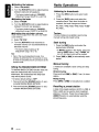
Radio Operations
Listening to broadcasts
1. Press the [SRC] button and select radio
mode.
2. Press the [BND] button and select the
reception band. Each time the button is
pressed, the band changes as follows:
F1 (FM1) .. F2 (FM2) .. F3 (FM3) .. AM ..
F1 (FM1) ...
• Adjusting the non-fader volume
Tuning
Adjust volume output from the unit's non-fader
output terminal.
3 tuning modes are available: seek tuning,
manual tuning and preset tuning.
2-1. Select "NF VOL".
3-1. Turn the [ROTARY] knob clockwise to
increase volume; turn counterclockwise to
decrease volume.
* The factory default setting is "0".
(Adjustment range: +6 to -6)
Note:
• When in the sound adjustment mode, if no
operation is performed for 10 seconds or more,
the mode is cancelled and the unit returns to the
previous mode.
Setting the MAGNA BASS EXTEND
The MAGNA BASS EXTEND function does not
adjust low frequencies like normal sound
adjustments, but emphasizes the deep bass
range with dynamic sound.
* The factory default setting is "OFF".
1. Press and hold the [SOUND] button (1 sec.)
to enable MAGNA BASS EXTEND.
2. Press and hold the [SOUND] button (1 sec.)
to disable MAGNA BASS EXTEND.
10
CZ109
Seek tuning
1. Press the [BND] button and select the
desired band (FM/AM).
* If "MANU" appears in the display, press and
hold the [BND] button (1 sec.). "MANU" will
turn off, and seek tuning will be enabled.
2. Press [~] or [~] to automatically seek a
station.
Manual tuning
2 modes are available: Quick tuning and step
tuning.
• Quick tuning
Press and hold [~] or [~] (1 sec.) to tune a
station.
• Step tuning
Press [~] or [~] to manually tune a station.
Recalling a preset station
A total of 24 preset positions (6-FM1, 6-FM2, 6FM3, 6-AM) can be used to store broadcast
stations in memory. Press the corresponding
[DIRECT] button to automatically recall the
stored frequency.
Manual memory
1. Use seek tuning or manual tuning to select
the desired station.
2. Press and hold one of the [DIRECT] buttons
(2 sec.) to store the current station in preset
memory.
Auto store
The auto store function stores up to 6 stations
automatically tuned in sequential order. If 6
stations cannot be found, any previously stored
station remains in its memory position.
1. Press the [BND] button and select the
desired band (FM/AM).
2. Press and hold the [~~,i] button (2 sec.). The
stations with good reception are stored
automatically to the preset channels.
* If auto store is performed in the FM bands, the
stations are stored in FM3 even if FM 1 or FM2
was chosen for storing stations.
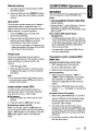
CDIMP31WMA Operations
MP3/WMA
This unit supports to play MP3IWMA files.
Notes:
• If you playa WMA file with active DRM (Digital
Rights Management), no audio is output (WMA
indicator flashes).
• Windows Media TM, and the Windows ® logo are
trademarks, or registered trademarks of
Microsoft Corporation in the United States and/or
other countries.
• To disable DRM (Digital Rights
Management)
1. In Windows Media Player 9/10/11, click on
TOOL ~ OPTIONS ~ MUSIC RECORD tab.
Under Recording settings, unclick the check
box for RECORD PROTECTED MUSIC.
Then reconstruct files.
Use personally constructed WMA files at
your own responsibility.
Preset scan
Preset scan sequentially receives stations
stored in preset memory. This function is useful
when searching for a station stored in the
memory.
1. Press the [~~,i] button.
2. When the desired station is received, press
the [~~~] button again to continue receiving
that station.
Note:
• Do not press and hold the [~~,i J button (2 sec.),
or the auto store function will begin and the unit
will begin storing stations.
Instant station recall (lSR)
The ISR function allows instant access to a
favorite preset station. The function operates
even when the unit is in other modes.
elSR memory
1. Select the station you wish to store in ISR
memory.
2. Press and hold the [ISR] button (2 sec.).
• Recalling a station with ISR
While in any mode, press the [ISR] button to
turn on the radio function and tune the selected
station. "ISR" appears on the display. Press the
[ISR] button again to return to the previous
mode.
Precautions when creating MP31
WMA files
e Usable sampling rates and bit rates
1. MP3: Sampling rate: 8 kHz-48 kHz,
Bit rate: 8 kbps-320 kbps / VBR
2. WMA: Bit rate: 48 kbps-192 kbps
• File extensions
1. Always add a file extension ".MP3" or
".WMA" to MP3 or WMA files using single
byte characters. If a different or no file
extension is appended, the file cannot be
played.
2. Files without MP3IWMA data will not play.
Instead, "- -:- -" will appear in the play time
display.
e Logical format (File system)
1. When writing MP3IWMA files on a CD-R or
CD-RW disc, select "IS09660 level 1, 2, or
JOLI ET or Romeo" as the software format.
Normal playback may not be possible if
recorded in other formats.
2. The folder name and file name can be
displayed as the title during MP3IWMA play.
However titles must be within 64 single byte
alphabetical letters and numbers (including
extension).
3. Do not affix a name to a file inside a folder
with the same name.
CZ109
11
• Number of files or folders
Loading a CD
1. Up to 256 files can be recognized per folder.
Up to 578 files can be played.
2. Tracks are played in the order they were
recorded onto the disc. (Tracks may not
always be played in the order displayed on
the PC.)
3. Some noise may occur depending on the
type of encoder software used for recording.
1. Insert a CD into the centre of the CD SLOT
with label facing up. "LOADING" appears in
the display, the CD enters the slot, and play
begins.
Notes:
• If the CD does not enter easily, another CD may
be in the unit, or the unit may require service.
• Discs without the [Q]O'§@ or
ROMs are not supported.
I>IOITALAUllIll
Disc-In-Play function
This function automatically turns on unit power
and begins disc play if a disc is inserted when
the car's ignition key is turned to the ON or ACe
position.
• Do not insert hands, fingers, or other
foreign objects into the disc insertion sl'ot.
• Do not insert discs with adhesives such as
cellophane tape or rental CD labels
attached, or discs with marks left from
removal of such adhesives, since the disc
may become stuck and damage the unit.
Ejecting a CD
1. Press the [~] button to eject the CD. Take it
out from the ejected position. "EJECT'
appears in the display.
Notes:
• If you force a CD in before auto reloading, you
may damage the CD.
·If a CD (12 cm) is left ejected for 15 seconds, it
will be automatically reloaded (auto reload).
Listening to a disc already loaded in
the unit
Press the [SRC] button to select CD/MP3IWMA
mode.
When the unit enters this mode, playback starts
automatically.
If no disc is loaded, "NO DISC" appears in the
title display.
mark and CD-
• Some CD-RICD-RW discs may not be usable.
Pausing play
1. Press the [:~I~] button to pause play.
"PAUSE" appears in the display.
2. To resume CD play, press the
[:~I~] button
again.
Displaying CD titles
This unit can display title data for CD-texVMP31
WMA discs.
1. Each time the [DISP] button is pressed, the
title display will change.
• CD·TEXT discs
Track
~
Disc
~
Artist
~
• MP3IWMA discs
Track ~ Folder ~ Title
Track ...
Track ...
~
Album
~
Artist
~
Notes:
• If the CD playing is not a CD-text disc or no user
title has been input, "NO TITLE" appears in the
display.
• If an MP31WMA disc has no Tag input, "NO
TITLE" appears in the display.
• This unit supports MP31D3 Tags V2.3 I 2.2 11.1 I
1.0.
• Tag display gives priority to V2.3 I 2.2.
• For WMA album Tags, the information written into
the extension header is displayed.
·'S08859-1, ASCII, S-JIS characters can be
displayed in Tags.
UNKNOW characters can be turned into
IS08859-1 characters.
• Titles up to 32 bytes can be displayed in COl
MP31WMA mode.
12
CZ109
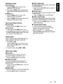
Selecting a track
• Folder repeat play
• Track advance
Repeatedly plays all tracks of the current folder
on an MP3IWMA disc.
1. Press the [~] button to move to the
beginning of the next track.
2. Each time the [~] button is pressed, the
track advances to the beginning of the next
track.
• Track back
1. Press the [~] button to return to the
beginning of the current track.
1. Press and hold the [RPT] button (1 sec.) for
folder repeat play.
• Random play
This function plays all tracks recorded on a disc
in random order.
1. Press the [ROM] button for random play.
• Folder random play
2. Press the [~] button twice to return to the
beginning of the previous track.
This function plays all the tracks of all the folders
recorded on an MP3IWMA disc in random order.
Fast-forwBrdlfast-reverse
1. Press and hold the [ROM] button (1 sec.) for
folder random play.
• Fast-forward
• To cancel play modes
1. Press and hold the [~] button (1 sec.).
1. Press the button previously selected.
• Fast-reverse
* The play mode is canceled and the off mode
1. Press and hold the [~] button (1 sec.).
appears in the display for 2 seconds.
* If the error display "- -:- -" appears, these
modes (Scan/Repeat/Random) can be canceled
while still in play mode.
* For MP3IWMA discs, some time is required until
to initiate movement between tracks. Also, some
error may occur in the playing time.
Folder select
Select a folder containing MP3IWMA files and
begins playing the first track in the folder.
1. Press [UP] or [ON].
Press the [UP] button to move to the next
folder. Press the [ON] button to move to the
previous folder.
2. To select a track, press [~] or [~].
Other play modes
.Scan play
This function locates and plays the first 10
seconds of all tracks recorded on a disc.
1. Press the [SCN] button for scan play.
• Folder scan play
This function locates and plays the first 10
seconds of the first tracks of all folders on an
MP3IWMA disc.
1. Press and hold the [SCN] button (1 sec.) for
folder scan play.
• Repeat play
This function plays the current track repeatedly.
1. Press the [RPT] button for repeat play.
CZ109
13
Operations Common to
Each Mode
To change settings
1. Press and hold the [DISP] button (1 sec.)
to switch to the adjustment display.
2. Press [~] or [~] to select the "item
name" as follows:
"CLOCK" - "SETTINGS" - "SCRN SVR"
-"SCROLL" - "DIMMER" - "TEL-SP"
- ''TEL-SW''
* The adjustment item will be displayed for 2
seconds before showing the desired value.
3. Turn the [ROTARY] knob to select the
desired value.
* When "ENT' is flashing in the display, press
the [:~I~ ] button to adjust setting value.
4. After completing settings, press the [DISP]
button to return to the previous mode.
• Setting the clock
3-1. Press the [:~~] button
3-2. Press [~] or [~] to select the hour or
minute.
3-3. Turn the [ROTARY] knob to set the time.
* The clock is displayed in 12-hour format.
3-4. Press the [:~~] button to store the time in
memory and return to the previous mode.
Note:
• You cannot set the clock when it is displayed
with only the car's ignition on. If the car's battery
dies or is removed, or the unit is removed, the
clock will be reset. If another button/operation is
selected while setting the clock, the clock set
mode is canceled.
• Displaying the settings
You can see the state of current settings at any
operation mode.
2-1. Select "SETTINGS".
3-1. Turn the [ROTARY] knob to display the
current settings.
* When the setting is selected, the current
state will be displayed after 1 second.
r1-I1I::}{
14
CZ109
This unit has a screen saver function in which
various patterns and random characters can be
displayed on the operation status indication
area. This function can be turned on/off. If a
button is pressed while the screen saver is on,
the corresponding operation display is shown
for about 30 seconds, and then the display
returns to the screen saver.
* The factory default setting is "ON".
2-1. Select "SCRN SVR".
3-1. Turn the [ROTARY] knob to select "ON" or
"OFF".
• Setting title scroll method
Set how to scroll in CD-TEXT and MP3IWMA
titles.
* The factory default setting is "ON".
2-1. Select "SCROLL".
3-1. Turn the [ROTARY] knob to select "ON" or
"OFF".
• ON: Scroll automatically.
• OFF: Scroll 1 time only.
• Setting dimmer control
2-1. Select "CLOCK".
Example:
• Turning the screen saver onloff
After 1 second:
(r1-B
[JfJ
Dimmer control can be set "ON" or "OFF".
* The factory default setting is "ON".
2-1. Select "DIMMER".
3-1. Turn the [ROTARY] knob to select "ON" or
"OFF'.
• Setting car speaker output for cell
phones
When the AUX input jack is used to connect an
AUX BLUETOOTH BB (BLT370) (sold
separately) :
* The factory default setting is "RIGHT'.
* To output the telephone calls, set cell phone
interrupt to "ON".
2-1. Select ''TEL-SP".
3-1. Turn the [ROTARY] knob to select "RIGHT'
or "LEFT'.
• RIGHT: Telephone calls can be heard on
the front right speaker connected to this
unit.
• LEFT: Telephone calls can be heard on
the front left speaker connected to this
unit.
• Cell phone interrupt setting
If you connect this unit and your cell phone with
an optional cable, you can listen to your calls on
your car speakers.
When the AUX input jack is used to connect an
AUX BLUETOOTH BB (BLT370) (sold
separately):
* The factory default setting is "OFF".
2-1. Select "TEL-SW".
3-1. Turn the [ROTARY] knob to select setting.
When turning the [ROTARY] knob, the
setting changes as follows:
"OFF"
e
+--+
"ON"
+--+
"MUTE"
OFF: This unit continues normal
operation even when the cell phone is
used.
• ON: Telephone calls can be heard from
the speakers connected to the unit.
* When listening to calls on your car speakers,
turn the [ROTARY] knob to adjust the
volume.
• MUTE: The sound from this unit is muted
during telephone calls.
Note:
• If connecting a hands-free kit, make sure the
setting is ON to receive telephone audio through
the system.
AUX function
An external input jack (AUX) is provided on the
front panel to allow playback of sound and
music from external devices.
• Selecting AUX IN sensitivity
Make the following settings to adjust sensitivity
when the sound from an external device is
difficult to hear even after adjusting the volume.
* The factory default setting is "MID".
1. Press and hold the [DISP] button (1 sec.).
2. Select "AUX SENS".
3. Turn the [ROTARY] knob to select "HIGH",
"MID" or "LOW".
Note:
• When AUX mode is selected, AUX IN sensitivity
can be set.
CZ109
15
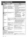
7. TROUBLESHOOTING
Replace with a fuse of the same amperage. If the fuse
blows again, consult your dealer.
Power does not
turn on.
(No sound)
Incorrect wiring.
Consult your dealer.
No sound when
operating the unit
with amplifiers or
power antenna
attached.
Power antenna lead is short
circuited, or excessive
current is required for
remotely powering on the
amplifiers or power antenna.
1. Turn the unit off.
2. Remove all wires attached to the power antenna
lead. Check each wire for possible short circuits
using an ohm meter.
3. Turn the unit back on.
4. Reconnect each amplifier remote wire to the power
antenna lead one by one. If the amplifiers turn off
before all wires are attached, use an external relay
to provide remote power-on voltage (excessive
current required).
Nothing happens
when buttons are
pressed.
Microprocessor malfunction
due to noise, etc.
1. Turn off power, then press the
[RELEASE] button and remove
the DCP.
2. Use a thin rod to hold reset
button depressed (2 sec.).
If the reset button is pressed
when a disc is loaded, please
eject the disc and load it once
again before attempting to play
it.
DCP or main unit connectors Wipe dirt off with a soft cloth dampened with cleaning
alcohol.
are dirty.
The speaker protection circuit 1. Turn down sound volume. Function can also be
restored by turning power off and on again.
is operating.
(Speaker volume is reduced automatically when
the speaker protection circuit operates).
2. If the sound is still muted, consult your dealer.
MP3JWMA files are absent
on disc.
Write MP3JWMA files onto disc properly.
Files are not recognized as
MP3JWMA files.
Use properly encoded MP3JWMA files.
File system is not correct.
Use IS09660 level 1,2 or JOLIET or Romeo file
system.
CD is dirty.
Clean the CD with a soft cloth.
CD is heavily scratched/
warped.
Replace with a CD without scratches.
Sound cuts out or MP3JWMA files are not
encoded properly.
skips.
Noise is
generated/noise is
mixed with sound.
Sound is poor
when power is
first turned on.
Let dry for about 1 hour with power on.
Condensation may form on
the internal lens when the car
is parked in a humid place.
File system is not correct.
16
CZ109
Use properly encoded MP3JWMA files.
Use IS09660 level 1,2 or JOLIET or Romeo file
system.
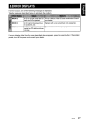
8. ERROR DISPLAYS
If an error occurs, one of the following messages is displayed.
Take the measures described below to eliminate the problem.
A CD is caught inside the CD This is a failure of the CD deck mechanism. Consult
your dealer.
deck and is not ejected.
A CD cannot be played due
to scratches, etc.
Replace with a non-scratched, non-warped disc.
A CD is loaded upside-down Eject the disc and reload properly.
inside the CD deck and does
not play.
If an error display other than the ones described above appears, press the reset button. If the problem
persists, turn off the power and consult your dealer.
CZ109
17
9. SPECIFICATIONS
FM Tuner
General
Frequency Range: 87.9 MHz to 107.9 MHz
Power Supply Voltage:
Usable Sensitivity: 9 dBf
50dB Quieting Sensitivity: 15 dBf
14.4 V DC (10.8 to 15.6 V allowable), negative
ground
Alternate Channel Selectivity: 70 dB
Stereo Separation (1 kHz): 35 dB
Current Consumption: Less than 15 A
Frequency Response (±3 dB): 30 Hz to 15 kHz
Weight / Source unit: 2.53 lb. (1.15 kg)
Speaker Impedance: 4 Q (4 Q to 8 Q allowable)
Weight / Remote control unit:
AM Tuner
1.41 oz. (40 g) (including battery)
Usable Sensitivity: 25 IJV
Dimensions / Source unit:
7" (Width) X 2" (Height) X 6-1/8" (Depth)
[178 (W) X 50 (H) X 155 (D) mm]
CD Player
Dimensions / Remote control unit:
Frequency Range: 530 kHz to 1710kHz
System: Compact disc digital audio system
Usable Discs: Compact disc
Frequency Response (±1 dB): 5 Hz to 20 kHz
Dynamic Range (1 kHz): 85 dB
Harmonic Distortion: 0.01 %
Audio
Maximum Power Output: 200 W (50 W X 4 ch)
Bass Control Action (100 Hz): +14 dB, -14 dB
Treble Control Action (10 kHz): +14 dB, -14 dB
Line Output Level (CD 1 kHz): 1.8 V
18
CZ109
1-3/4" (Width) X 4-5/16" (Height) X 7/16"
(Depth)
[44 (W) X 113 (H) X 11 (D) mm]
Power Output :
20 W RMS x 4 Channels at 4
and 1 % THD+N
Signal to Noise Ratio:
88 dBA (reference: 1 W into 4 )
Note:
• Specifications and design are subject to change
without notice for further improvement.
Clarion Co., Ltd.
2008/10
All Rights Reserved. Copyright © 2008: Clarion Co" Ltd.
Printed in China / irnprirne en Chine / Impreso en China
PE-31598
280-8722-00
Printed In China I Impnme en Chine/lmpre"so:..;'"",,Ch:..;";;;'
•
-
1:'-' ••••••
--..- . ~ -... ..
---:o2;::OO"'B/:..:',,'
..:2"'84"'-...:1"'37:..:8:..-0"'0::....
--,
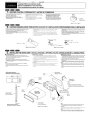
InstallationlWire Connection Guide
Manuel d'installation et de connexion
Gufa de instalaci6n/conexi6n de cables
........
........
-1.
BEFORE STARTING I PREPARATIFS I ANTES DE COMENZAR
1. This set is exclusively for use in cars with a 12 V
power supply, negative ground.
2. Read these instructions carefully.
3. Be sure to disconnect the battery "9" terminal
before starting, This is to prevent short circuits during
installation. (Figure 1)
,. Cet appareil est exctusivement destine a etre utilise
dans les voitures avec une alimentation 12 V a masse
negative.
2. lire ces instructions attentivement.
3. S'assurer de debrancher la borne
de la battene
avant de commencer. Cela evitera les court-eircuits
pendant !'instaliation, (Figure 1)
-e-
1, Esta unidad ha side disefiada para utitizarse
exclusivamente en autom6viles can fuente de
alimentaci6n de 12 V, Y negativo amasa.
2, Lea cuidadosamente estas instrucciones.
3. Antes de comenzar, cerci6rese de desconectar
ellerminal "9" de la bateria. Esto es para evitar
cortocircuitos durante Ia instalaci6n. (Figura 1)
@r
G
ffi
........
-2.
Car battery
Banene de vollure
Batef'Ha del autom6vil
Figure 1 I Figure 1 I Figura 1
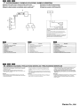
CAUTIONS ON INSTALLATION I PRECAUTIONS AU SUJET DE L'INSTALLATION I PRECAUCIONES PARA LA INSTALACION
1. Prepare all articles necessary for installing the source unit before starting.
2. Install the unit within 30° of the horizontal plane. (Figure 2)
3. II you have to do any work on the car body, such as drilling holes, etc.,
consult your car dealer beforehand.
4. Use the enclosed screws for installation. Using other screws can cause
damage. (Figure 3)
,. Avanl de commencer. preparer toutes les pieces ne<:essaires pour installer
rappareil pilote.
30° par rapport I'horizontal.
(Figure 2)
3 S'il est necessaire d'effectuer certains travaux sur la carrosserie comme
percer des trous, etc., consulter d'abord votre concessionnaire automobile
4. Utiliser les vis lournies pour I'installation. L'utilisation d'autres VIS peut causer
des dommages. (Figure 3)
2. Installer I'appareil avec un angle inferieur
a
@
a
1. Antes de comenzar, prepare todos los elementos necesarios para instalar la
unidad fuente.
2. Instale la unidad con un angulo de 30° sobre et plano horizonta1. (Figura 2)
3. SI tiene que realizar cualquier trabajo en la carroceria, como taladrado de
orificlos, etc" consulte al proveedor de su autom6vil.
4. Use los tomilios incluidos para la instalaci6n. EI uso de otros tomitlos puede
causar danos, (Figura 3)
Chassis I Chassis I Chasis
Chassis / Chassis I Chasis
jL
~_-_-_- O,mage' Oommage' Oano
Max. eccmccm"""',"""a-mccm-m""a-x.1 Max. 8 mm
........
-3.
Figure 21 Figure 2/ Figura 2
Figure 3/ Figure 3/ Figura 3
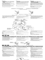
INSTALLING THE SOURCE UNIT I INSTALLATION DE L'APPAREIL PILOTE IINSTALACION DE LA UNIDAD FUENTE
• Montage universel
• Universal Mount
1. Place the universal mounting bracket into the instrument panel, use a
screwdriver to bend each stopper of the universal mounting bracket inward,
then secure the stopper as shown in Figure 4.
2. Wire as shown in Section 6.
3. Insert the source unit into the universal mounting bracket until it locks.
4. Take care of the top and bottom of the outer escutcheon and mount it so that
all the hooks are locked.
Notes:
• Some car models require special mounting kits for proper installation.
Consult your Clarion dealer for details.
• Fasten the front stopper securely to prevent the source unit from coming
loose.
• Console opening dimensions
• Dimensions d'ouverture de 18 console
• Olmensiones de la abertura de la consola
I"
L
Hole
Trou
Orificio
(182mm)
Orificio
i
1. Coloque el saporte de montaje universal en eltablero de instrumentos, utilice
un destomillador para doblar cada relen del sapone de montaje universal
hacla adentro, y despues asegure el reten como se muestra en la Figura 4.
2, Conecte los cables como se muestra en Ia Secci6n 6.
3. Inserte la unidad fuente en el saporte de montaje universal hasta que Quade
enganchado.
4. Tenga cuidado can la partes superior e inferior de la pieza ornamental
exterior, y m6ntela de forma que todos los ganchos queden bloqueados.
Notas:
• Algunos modelos de automdviles requieren juegos de montaje especiales
para reaJizar la instalaci6n apropiada. Solicite los detaf/es a su proveedor
Clarion.
• Apriete can seguridad el reten frontal para evitar que se af/oje la unidad
fuente.
lnstrument panel
Tableau de bord
Tab!ero de instrumentos
Stoppers
Languetles
Retenes
- "~-'-~, '~_'_ -----l]~~
__
• Montaje universal
1. Placer Ie support de montage universel dans Ie tableau de bard. utiliser
un tournevis pour replier vers I'exleneur chaque langueue du support de
monlage universel. puis fixer les languettes camme montre sur la Figure 4.
2. Cabler comme monlre dans la Section 6,
3. Inserer I'appareil pIlote dans Ie support de montage universel jusqu'a ce qu'il
soit bloque.
4. Reperer Ie haut et Ie bas de I'ecusson exleneur et Ie monter de maniere que
taus les crochets SOlent verroult1es.
Remarques:
• Certains modeles de voiture necessitent un kit de montage special pour une
Ins/al/ation correcte. Consulter Ie revendeur Clarion pour les details.
• Serrer {ermement fa languette avant pour eviter que f'appareil pilote ne se
desserre.
.
:s> ,..,.
/~
....,.--
~
Hexagonal bolt
Ecrou hexagonal
Perno hexagonal
Strap
Armature
Banda
..,
• This part is not provided in some models.
~ Cette piece n'existe pas sur tous les modeles,
• Esta pieza no se suministra con algunos modelos.
Top
Haut
Parte superior
t
Tournevis
Destornillador
Spring
Ressort
Resorte
Stoppers
Langueltes
Retenes
Bottom
Bas
Parte inferior
Outer escutcheon side view
~
Outer escutcheon
Ecusson exterieur
Pleza ornamental exterior
Vue lateraIe de I'ecusson exterieur
Figure 4/ Figure 41 Figura 4
Note:
• Before attaching the universal mounting bracket, slightly bend the spring
toward the inside with your fingers and attach it to the side of car,
Remarque:
• Avant de fixer Ie patin de montage universe/, pliez legerement Ie ressort vers
I'interieur avec les doigts et fixez-Ie sur Ie cote de /a voiture.
Nota:
• Antes de fijar al soporte de montaje universal, doble ligeramente al resorta
hacia el interior con los dedos y fije/o en la parte lateral del autom6vil.
• Montage fixe
(TOYOTA, NISSAN et autres vehicules equipes ISOIDIN)
• Fixed Mount
(TOYOTA, NISSAN and other ISO/DIN equipped
vehicles)
Cel appareil est con~u pour une installation fixe dans Ie tableau de bordo 5i Ie
vehicule est equipe d'un auto-radio insta1h!! I'usine, installer I'appareil pilote
avec les pieces et les ecrous marquees de (*) (Figure 7),
5i Ie vehicule n'est pas equipe d'un auto-radio installe rusine se procurer un
kit d'installalion pur installer I'appareil pilote avec la procedure suivante.
a
This unit is designed for fixed installation in the dashboard.
If the vehicle is equipped with a ractory-installed radio, inslaUthe source unit
with the parts and screws marked
(Figure 7).
If the vehicle is nol equipped with a factory-installed radio, obtain an instatlation
kit to install the source unit in the following procedure.
a
(*>
Coubez la butee apres les operahons ci-dessous lorsque I'apparei! pilote est
installe sur un "ehicule TOYOTA. NISSAN et autres vehicules equipes 1501
DIN.
Bend the stopper following the procedures below when this source unit is
installed 10 the TOYOTA, NI$$AN and other ISQIDIN equipped vehicles.
1. Coubez la butee de l'appareit source, (Figure 5, 6)
1. Bend the stopper from the source unit. (Figure 5, 6)
• Montaje fijo
(Automovlles TOYOTA, NISSAN, Y otros
provlstos de normas ISO/DIN)
Esta unidad ha sido disenada para instalarse de forma iija en el tablero de
instrumentos. Si el autom6vil dispone de una radio instalada en fabrica, instale
la unidad fuente con las piezas y los tomillos marcados con (*) en la Figura 7,
Si el autom6vil no dispone de una radio instalada en fabrica, adquiera un juego
de instalaci6n para instalar la unidad fuente de acuerdo con el procedimiento
siguiente,
Doble de instalar esta unidad en vehfculos TOYOTA, NISSAN, y otoros
equipados con ISOIDIN, extraiga el reten siguiendo los procedimientos
indicados a continuaci6n.
1. Doble el reten procedente de la unidad fuente, (Figura 5, 6)
AFTER BEND/APRES LA COURBUREIDESPUES DE DOBLAR
BEFORE BEND/AVANT LA COURBUREIANTES DE DOBLAR
STOPPER/TOURNEVISIDESTORNILLADOR
SOURCE UNIT/APPAAEIL PILOTElUNIDAD FUENTE
Figure 5 I Figure 5 I Figura 5
Figure 6 I Figure 61 Figura 6
2, Fixer Ie support de montage sur Ie chassis comme montre sur la Figure 7.
Les trous sont pre-decoupes pour les vehicules TOYOTA et NISSAN; des
modification du support de montage, comme Ie perl;age de nouveaux trous.
peuvent etre necessaire pour les autres modeles.
3. Cabler comme montra dans la Section 6,
4. Fixer I'appareil dans Ie tableau de bord puis remonter Ie tableau de bord et Ie
panneau central
2, Secure the mounting brackets to the chassis as shown in Figure 7, Holes are
pre-tapped for TOYOTA and NISSAN vehicles; modification, such as drilling
new holes, of the mounting brackets may be required for other models.
3, Wire as shown in Section 6.
4, Secure the unit in the dashboard. and then reassemble the dashboard and
the center panel.
2. Asegure los soportes de montaje al chasis como se muestra en la Figura 7,
Los orificios ya han sido taladrados en los autom6viles TOYOTA y NISSAN,
pero para olros modelos puede resultar necesario realizar modificaciones,
como taladrado de nuevos orificios en los soportes de monlaje,
3. Conecte los cables como se muestra en la Secci6n 6.
4. Asegure la unidad al tablero de instrumentos, y despu6s vuelva a montar et
tablero de instrumentos y el panel centraL
Mounting bracket.
(1 pair lor the left and right sides)
Support de montage.
(1 pairs, pour les faces gauche at droite)
$oporte de rnontaje •
(1 par para los !ados izquierdo Yderecho)
(il,"-.
(il<~ '~
*~ '-"'::::
"-.
* f!#"""" I
Center Panel (Note 1)
Panneau central (Remarqure 1)
Panel central (Nota 1)
• ; The parts and screws with this mark are used to install radio or included in
the installation kit.
The screws with this mark are originally anached to the vehicle,
*:
Note 1:
• In some cases, the center panel may require some modification (trimming,
filling, etc.).
Note 2:
• If a hook on the installation bracket interferes with the unit, bend and flatten it
with a nipper or a similar tool.
les pieces et les vis portant cette marque sont ulilisees pour i'autoradio
Installe ou loumies dans Ie kit d'lnstaliatlon.
Les vis portant cene marque sont faurnies d'origine avec Ie vehicule.
Remarque 1:
• Dans certains cas, Ie panneau central peul necessite certaines modifications
(ebarbage. remplissage, etc.).
Remarque 2:
• Si un crochet du support d'installation interfere avec I'appareil, Ie tordre et
raplatir avec une pince au un outil simi/aire.
*:
• : Las piezas y tomillos con esla marca se utilizan para instalar la radio 0 se
suministran can el juego de instalacion.
Los tOmillos con esta marca estan originalmente fijados a los automoviles.
Nota 1:
• En algunos casos, el panel central puede requerir ciertas modificaciones
(recone, limado, etc.),
Nota 2:
• Si algun gancho del sapone de montaje interfiere can la unidad, d6blelo y
aplane/o can unos alicates u otra herramienta similar,
*:
. . . . GEl
-4.
REMOVAL OF THE SOURCE UNIT I DEPOSE DE L'APPAREIL PILOTE I DESMONTAJE DE LA UNIDAD FUENTE
1. When removing the source unit, disassemble it in the reverse of the order in
Section ~3. INSTALLING THE SOURCE UNIT'.
2, Remove the Detachable Control Panel (DCP),
• For instructions on removing the DCP, refer to the owner's manual.
3. Press the outer escutcheon upward and remove it. (Figure 8)
4, Insert and lock the hook plates. (Figure 9)
5. Pull the hook plates to remove the source unit.
1. Lors de la depose de I'appareil pilote, demonter dans I'ordre inverse de la
Section ~3, INSTALLATION DE L'APPAREIL PILOTE"
2. Deposer Ie clavier de commande amovible (DCP),
• Pour les instructions sur Ie retrait du clavier de commande amovible (DCP),
se referer au mode d'emploi.
3. Presser I'ecusson exterieur "ers Ie haut et Ie retirer, (Figure 8)
4. Inserer et verrouilter les plaques a crochet. (Figure 9)
5. Tirer sur les plaques a crochet pour retirer rappareil pilote.
1. Para desmontar la unidad fuente, realice el procedimiento inverso al de la
Secci6n "3. INSTALACION DE LA UNlOAD FUENTEn •
2, Desmonte el panel de control desmontable (DCP).
• Para instrucciones sobre como desmontar el OCP, consulte el manual de
instrucciones.
3, Presione la pieza ornamental exterior hacia afuera y extraigala. (Figura 8)
4. Inserte y bloquee las placas de enganche. (Figura 9)
5. Tire de las placas de enganche para extraer la unidad fuente,
Outer escutcheon
Ecusson exterieur
Pieza ornamental exterior
. . . . GEl
-5.
FigureB/Figure8/FiguraB
CAUTIONS ON WIRING I PRECAUTIONS AU SUJET DES CONNEXIONS I PRECAUCIONES PARA LA CONEXION DE CABLES
1. Be sure to turn the power off when wiring,
2. Be particularly carelul where you route the wires. Keep them well away from
the engine, exhaust pipe, etc. Heat may damage the wires.
3. If the luse should blow, check that the wiring is correct.
II it is, replace the fuse with a new one with the same amperage rating as the
original one. (Figure 10)
Note:
• There are various types of fuse holder. Do not let the battery side touch other
metal parts.
4, Gonnectthe CeNET eldension cable fully and securely until it locks, When
the CeNET extension cable is pulled, hold the slide cap part and pull it
towards you.
• When the CeNET extension cable is extended or branches, use extension
cable GCA-520 (2,5m) or CGA-521 (O,6m), or Y-adapter CCA-519 (each of
them is sold separately).
• Use the CeNET extension cable made by Clarion,
5, When the main power supply fuse in the car is 15 A or less, purchase an
automotive cable that can withstand 15 A and supply this unit with power
directly Irom the battery to ensure that the unit will operate normally.
Note that a fuse must be installed at a distance no longer than 30 em from
the cable battery terminal to prevent accidents.
1. S'assurer de meltre I'apparell hors Circuit avant de falre Ie cablage.
2. Faire particulierement attention Iors de I'acheminement des fils,
Les eloigner du moteur. des tuyaux d'echappemenl. etc. La chaleur risque
d'endommager ces fils.
3. Si Ie fusible saute, venlier si Ie cablage est correct.
Si Ie fusible est grille. Ie remplacer par un fusible neuf de meme amperage
que Ie fusible d'origine, (Figure 10)
1. Antes de hacer las conexiones, asegurese de desconectar la alimentaci6n
de la unidad.
2, Sea especialmente cuidadoso al dirigir y fijar los cables. mantEmgalos
alejados del motor, tubo de escape, etc. El calor puede danar los cables.
3. Si el fusible se quema, revise las conexiones.
Si eslA quemado, reemplace el fusible por otro nuevo con el misrno valor de
amperaje que el original. (Figura 10)
Remarque:
Nota:
• 1/ Y a different type de porle-Iusible. La borne du cole batferie ne doit pas
toucher d'autres pieces melalliques.
4. Connecter Ie cable d'extenslon CeNET completement et solidement jusqu'a
ce qu'il soit verrouille. Pour tirer Ie cable d'extension CeNET, tenir la partie
coulissante du capuchon et tirer vers vOlls.As
• Pour etendre au deriver Ie cable d'extension CeNET, utiliser Ie cable
d'extension CCA-520 (2,5 m [8 pieds)l ou CCA·521 (0.6m [2 piedsj), ou
I'adaptateur Y CCA-519 (ces cables sont vendus separement)
• Utiliser les cables d'eKtension CeNET fabriques par Clarion.
5. Si Ie fusible d'alimentation principale de la voiture est de 15 A ou moins,
achetez un cable automobile qui peut supporter 15 A et alimenter cet
appareil direclement a partir de la ballerie et assurer que rapparei!
lonctionnera normalement.
Notez qu'un fusible doH etre installe a une distance de moins 30 cm de borne
de la batterie pour eviter tout accident.
• Existen varios tipos de portafusibfes. No permita que el terminal dellado de
la bateria toque otras partes metalicas.
4, Conecte el cable prolongador CeNET completa y seguramente hasta que
chasquee. Para desconectar el cable, sujete la parte de la tapa deslizable y
tire hacia usted.
• Para prolongar 0 ramificar el cable prolongador CeNET, utilice un cable
prolongador CCA-520 (2,5 m) 0 CCA-521 (0,6 m), 0 un adaptador en Y
CCA-519 (vendidos aparte).
• Utilice un cable prolongador CeNET fabricado por Clarion.
5, Cuando el fusible de alimentaci6n principal del autom6vil sea de 15 A 0
menos, adquiera un cable para autom6"il que pueda resistir 15 A Y alimente
esta unidad directamente desde la baterfa para cerciorarse de que pueda
funcionar normal mente.
Tenga en cuenta que para evitar accidentes, debers instalar un fusible en al
cable que va a terminales de la baterfa a una distancia no superior a 30 em.
~
• . FU,se case
BOltler a fUSIble
Caja de f u s i b l e . ,
'
FUS.
~~~:~::
Figure 10 I Figure 101 Figura 10
IDiI . . . GIllllD
-6.
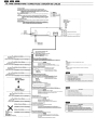
WIRE CONNECTIONS I CONNECTIQUE I CONEXION DE CABLES
To external amplifier
• To eliminate audio short drcuits, do not remove the caps of unused RCA cables.
CAUTION: Please make sure when connecting external power amplifier. that you
property. to the car chassis. ground the amplifier. If this Is not done, severe
damage to the source unit may happen.
~~~u~~:p~~:~~~~U:O~~:_~~Uits audio, ne pas retirer les capuchons des cables RCA non
A~~~~ioN:lorsque vaus raccordez un ampli de puissance externe, faltes bien
I
a
attention mettre correclement "amplifieateur it la masse sur Ie chassis
de I. vallure. Sinon, vaus rlsquez d'endommager gravement I'appareil
pilote.
A un amplificador externo
• Para eliminar los cortocircuitos de audio, no quite los casquiUos protectores de los cables
RCA no utilizados,
PRECAUCI6N:Cuando conecte un ampllflcador de potencla externo, cercl6rese de
ponerto adecuadamente a masa en el chasls de su autom6vll. Sl no 10
hlclese, 1a unidad fuente podria dafiarse serlamente.
<D
®
@
@
* RCA
:==:::»~==~
(CZ209 only)
(CZ209 seulement)
(8610 el CZ209)
Antenna
Antenne
Antena
~
~~~elecommande
Remote control
Control remota
1--------~Ef3~~-------
,
,
I
Front Right
Avant droit
Delantero den>cho
8Gray/BIack I 9Grislnoir I 8Grislnegro
16-Pin Connector extension Lead
(attached to the source unit)
AI prolongateur-eonnecteur 16 broches
(attache sur I'appareil pilote)
Cable prolongador de 16 contactos
(fijado a la unidad fuente)
Brown wire (Phone mute lead)*
Fil marron (fil de sourdlne de telephone)*
Conductor marr6n (Conductor de sllenclamlento de telefono)*
$White I 631Blanc I Ef)Blanco
,
,
Front Lett
Avant gauche
Delaotero izquierdo
I
8WhitelBlack I 8BlaflClnoir I 8B1ancolnegro
Rear Right
Arriere droit
Trasero derec:ho
<T>Green I EE>Vert I EBVerde
Rear Left
Arriere gauche
Trasero lzquierdo
8GreenIBlack I eVertlnoir I 8Verdelnegro
4·Speaker system
Systeme a 4 haut-parleurs
Sistema con 4 altavoces
+
+
2~Speaker system
Systeme a 2 haut·parleurs
Sistema con 2 altavoces
EBGray I Ef)Gris I Ef)Gris
Right
Droit
Derecho
eGraylBlack I 9Grislnoir l6)Grislnegro
Connect to cellular phone mute lead.
Brancher au fil de sourdine du telephone mobile.
Contklelo al conductor de silenciamiento deltelefono modular.
Yellow wire (Memory back-up lead)
Fil jaune (Iii de soutien memoire)
Conductor amarillo (Conductor de protecci6n de la memoria)
Connect directly to battery.
Brancher directement a la batterie.
Fuse (15A)
CoOOcl.elo directamente a la bateria,
Fusible (lSA)
Fusible (1SA)
Yellow wire (Bus power lead)*
Fil jaune (til de bus d'aHmentation)*
Conductor amarillo (conductor de alimentaclon de bus)*
Connect directly to battery.
Brancher directement a la ballerie.
Consctela directamente a la bateria.
Fuse (3A)
Fusible (3A)
Fusible (3A)
Red wire (Power lead)
Fil rouge (fil d'alimentation)
Conductor rajo (Conductor de alimentaci6n)
AccessoryEB12 V
Aceessoire®12 V
AccesorioE!112 V
BlueJWhite wire (Amplifier turn-on lead)
Fil bleulblanc (fil de mise sous tension lehkommandable de I'amplificaleur)
Conductor azullblanco (Conductor de conexiOn de la alimentaci6n del amplificador)
Note:
• Some units do not have connecting leads or jacks.
(Refer to *.J
Remarque:
• Cerrains appareils n'ont pas de conducteurs de connexion ou de prises.
(Voir *.)
Nota:
• Algunas unidades no tienen cables de conexi6n ni conectores.
(Refierase a *.J
Description
No.
(j)
FRONT RIGHT Gray (Red)
®
®
FRONT LEFT Gray (White)
@)
NON-FADER LEFT Purple (White)
OEM STEERING WHEEL REMOTE CONTROL INPUT JACK (Black)
®
NON-FADER RIGHT Purple (Red)
Description
No.
Connect to remote turn-on lead of amplifier.
Brancher au til de mise sous tension telecommandable de l'ampliflCateur.
Conectelo al conductor de conexi6n automatica de la
alimentaci6n del amplificador.
Black wire (Ground lead)
Fil noir (til de terre)
Conductor negro (Conductor de puesta amasa)
(j)
AVANT DROIT Gris (Rouge)
®
®
AVANT GAUCHE Gris (Blanc)
@)
GAUCHE Pourpre NON-FADER (Blanc)
®
PRISE D'ENTREE DE TEU~_COMMANDE SUR VOLANT OEM (Noir)
DROIT Pourpre NON-FADER (Rouge)
ffiWhite I EBBlanc I EBBlanco
Left
Gauche
Izquierdo
x
8WhiteJBlack I 8 Blanc/nair I 8Blancolnegro
Ef)Purple I EBPourpre I Ef)PUrpura
ePuopleJ8lack I ePourpreioor I epurpuralrregro
Connect to vehicle chassis ground.
Brancher a la terre du chassis du vehicule.
Conectelo a una parte melalica del chasis del vehfculo.
OrangelWhite wire (illumination lead)
Fil orangelblanc (fil d'eclairage)
Conductor anaranjadoJblanco (conductor de iluminaci6n)
Connect it to the car power suppty terminal for illumination.
Le connecter a la borne d'alimentation de I'eclairage de la voiture.
Conllctelo al terminal de alimentaci6n del autom6vil para iluminaci6n.
EBGreen I EBVertl EBVerde
Not used.
Insulate each wire.
eGreenIBlack I eVert/noir I everdelnegroj
Inutilise,
Isaler chaque fil.
o se utiliza.
Aisle todos los conductores.
Ll --------------------------
Blue wire (Auto antenna lead)
Fil bleu (fil de I'antenne electrique)
Conductor azul (conductor para la antena motorizada)
Connect it to the car power supply terminal for the antenna.
Le connecter a la borne d'alimenlalion de I'antenne electrique
de la voiture.
Conectelo al terminal de alimentaci6n de la antena.
(j)
Descripcl6n
DELANTERO DERECHO Gris (Roja)
®
DELANTERO IZQUIERDO Gris (Blanco)
@
SIN BALANCE DELANTERO-TRASERO Derecho violeta (Rojo)
No.
@)
SIN BALANCE DELANTERO-TRASERO Izquierdo violeta (Blanco)
®
TOMA DE ENTRADA DE CONTROL REMOTO PARA EL VOLANTE
OEM (Negro)
........
-7.
SYSTEM EXAMPLE I EXEMPLE DE SYSTEME I EJEMPLO DESISTEMA
• Example of the system using an external amplifier (Audio Visual)
• Exemple de systeme utilisant un amplificateur exterieur. (audio-visuel)
• Ejemplo de sistema utilizando un amplificador externo (audiovisual)
• Example of AUX Sluetooth SS connection
• Exemple de connexion AUX Sluetooth SS
• Ejemplo de conexi6n de AUX Bluetooth SS
~
I
I
I
I
---~--f-'-------------
6..1 or~o I
~
This system has an external input jack on the front panel, so you can
listen to your telephone calls or music from external devices on your
car speaker.
Comme ce systeme possede une prise d'entree externe sur Ie
panneau avant, vous pouvez ecouter vas appels leh~phoniques ou
de la musique provenanl de composants exlernes par les
haul-parleurs de volre voiture.
EsIs sistema liene una toma de entrada exterior en el panel frontal
para poder escuchar las lIamadas tetef6nicas 0 la musica de los
dispositivos externos por los altavoces del autom6vil.
Description
No.
No.
Description
No.
Descrlpcl6n
Appareil pilote
(j)
Unidad luenle
RCA extension cable (sold separately)
Q)
@
Cable de rallonge RCA (vendu separement)
@
Amplificateur de puissance 4 canaux
Front speakers
@
Haut-parleurs avant
Rear speakers
®
Haut-parleurs arrisre
Speakers
@
Haut-parleurs
(j)
External unit
®
®
®
®
®
®
Cable de extensi6n RCA
4·Channel power amplifier
Appareil exteme
Unidad extemo
®
®
Aux Bluetooth BB (BLT370)
@
Aux Bluetooth BB (BLT370j
(j)
@
Stereo mini-plug cable (sold separately)
®
Cable stereo
lID
Cable de minidavija estereo (vendido par separado)
(j)
®
®
®
®
®
Source unit
a mini-fiche (vendu separement)
Amplificador de potencia de 4 canales
Altavoces delanteros
Altavoces traseros
Altavoces
Bluetooth BB auxiliar (BLT370)
........
-8.
GENERAL CAUTIONS I PRECAUTIONS GENERALES I PRECAUCIONES GENERALES
1. Do not open the case. There are no user serviceable parts inside. If you drop
anything into the unit during installation, consult your dealer or an authorized
CLARION service center.
2. Use a soft, dry cloth to clean the case. Never use hard cloth, thinner.
benzen, alcohol, etc. For tough dirt, apply a little cold or warm water to a soft
cloth and wipe oN the dirt gentry.
IMPORTANT:
• Improper installation may cause damage to your unit or car. If you do not
have the appropriate experience, consult a qualified instaJler. Cutting chassis
wire leads voids the wa"anty.
1. Ne pas ouvrir Ie coif ret. II n'y a pas de pieces reparables par I"utilisateur
I'interieur de I'appareil. Si un objet est tomhe dans I'appareil pendant
rinstallation, consulter vOlre ravendeur au un service apres-vente agree
CLARION.
2. Utiliser un chiffon doux et sec pour nelloyer Ie call reI, ne jamais utiliser un
chiffon rigide, un diluant, du benzene. de I'alcool, etc. Pour enlever la salete
tenace, appliquer un peu d'eau Iroide ou tjade sur un chiffon doux at assuyer
doucementla salele.
IMPORTANT:
• Une instaflation inco"ecte peul endommager rappare!1 ou Ie vehicule. Si
f'on ne possede pas les connaissances requises, consulter un instalfateur
qualitie. Couper Ie fil du chassis annule la garanlie.
a
1. No abra la caja. En el interior no hay piezas que pueda reparar el usuario.
Si dentro de la unidad entra algo durante la instalaci6n, consulte a su
proveedor 0 a un centro de servicio autorizado por CLARION.
2. Para limpiar la caja, utilice un pano suave y seco. no use nunca un pano
duro, diluidor de pintura, benceno, alcohol, etc. Para la suciedad resistente.
aplique un poco de agua Iria 0 caliente a un pano suave y lrote suavemente
la parte sucia.
IMPORTANTE:
• La instalaciOn inapropiada puede causar dafios en su unidad 0 su autom6vil.
Si usted no posee la 6xperiencia apropiada, consulte a un instafador
cualificado. £1 corte de los conductores de puesta amasa (carroceria)
anulara la garantia.
Clarion Co., Ltd.
clarion
GARANTIE LIMITEE DE 1 AN CLARION
Pour Ie Canada et les Etats-Unis seulement
Ce produit Clarion vendu par marchand autorise Clarion est garanti contre tous defauts de materiel et de mise en
ceuvre pour une duree de un (1) an a compter de la date de vente initiale quand I'achat ET I'installation ont ete
effectues chez un marchand autorise Clarion.
Tous cablages, fils et autres accessoires Clarion achetes chez un marchand autorise Clarion, sont garantis contre tous
defauts de materiel et de mise en ceuvre pour une duree de quatre-vingt-dix (90) jours de la date d'achat initiale.
TOUT ACHAT DE PRODUITS CLARION EFFECTUE CHEZ UN MARCHAND NON-AUTORISE CLARION SERA
SOUMIS ADES RESTRICTIONS DE GRANANTIES DECRI CI-DESOUS.
Les conditions de cette garantie Iimitee et I'implication de la responsabilite de Clarion Corporation of America
"Clarion" sous cette garantie limitee sont les suivantes:
1. DANS LE CAS DE LA GARANTIE L1MITEE DE UN (1) AN, UNE PREUVE D'ACHAT ET UNE PREUVE
D'INSTALLATION SONT REQUISES. DES INFORMATIONS SUPPLEMENTAIRES CONCERNANT LES
CENTRES DES SERVICES AUTORISES PAR CLARION PEUVENT ETRE OBTENUES AUX ADRESSES
FIN DE CE DOCUMENT.
A LA
2. Cette Garantie Limitee sera annulee si un dommage est survenu au bien lors d'un service effectue par personne
ou entreprise qui n'est pas accredite comme un Centre de Service et Garantie Clarion.
a
a
3. Cette Garantie Limitee n'est pas applicable un aucun produit sujet I'abus, negligence, accidentes, installation
ou utilisation incorrects ou que les numeros de serie ont ete modifies, obstrue ou efface, ou qui a ete raccordes,
installes, ajustes ou repares autrement indique par Clarion.
4. Cette Garantie Limitee ne couvre pas des interferences electrostatiques, electriques, ni les ajustements ou
nettoyage de la tete de lecture (en cas de radio cassette) ou elements laser, ni les frais relies a la manutention pour
Ie retrait ou la reinstallation
5. La responsabilite de Clarion sous cette Garantie Limitee est limitee uniquement
du produit, qui est sujet uniquement a la discretion de Clarion.
a la reparation ou au remplacement
6. Ce produit doit est livree dans son emball age d'origine ou equivalent. Le colis doit etre entierement assure et tous
frais de transport doivent etre prepayes. Clarion n'assumera aucune responsabilite en cas de perte ou dommages
survenue lors du transport.
7. TOUS PRODUITS CLARION ACQUIS PAR UNE ENTREMISE AUTRE QU'UN MARCHAND AUTORISE PAR
CLARION, INCLUANT TOUS ACHATS VIA UN MARCHAND VIRTUEL (ACHAT INTERNEn QUI N'EST PAS
AUTORISE PAR CLARION, NE SONT PAS COUVERTS PAR LES GARANTIES L1MITEES DE CLARION, ET CE,
EN ACCORD AVEC LES LIMITATIONS DEFINIES PAR LA LOI. DANS LE CAS OU LES LOIS APPLICABLES NE
PERMETTENT PAS L'ELIMINATION DES GARANTIES SOUS CES CONDITIONS, LA PERIODE DE GARANTIE
L1MITEE QUI S'APPLIQUE AU PRODUIT SERA DE QUINZE (15) JOURS A PARTIR DE LA DATE D'ACHAT INITIALE.
8. AUCUNE GARANTIE IMPLICITE NE POURRA S'ETENDRE AU-DELA DE LA PERI ODE DE GARANTIE DECRITE
CI-DESSUS, ET CE, EN ACCORD AVEC LES L1MITES DEFINIES PAR LA LOI. CLARION NE POURRA EN AUCUN
CAS ETRE TENUE RESPONSABLE DES PERMETS OU DOMMAGES DIRECTS OU INDIRECTS DU A L'UTILISATION
ou L'IMPOSSIBILITE DAuTILISATON DU PRODUIT. PUISQUE CERTAINS ETATS NE PERMETTENT PAS DE
LIMITER LA DUREE DES GARANTIES IMPLICITES, OU DE LIMITER LA RESPONSABILITE EN CAS DE DOMMAGES
DIRECTS OU INDIRECTS, CES LIMITATIONS OU EXCLUSIONS PEUVENT NE PAS S'APPLIQUER A VOUS.
9. CETTE GARANTIE L1MITEE VOUS DONNE DES DROITS LEGAUX PRECIS. VOUS POUVEZ POSSEDER DES
DROITS SUPPLEMENTAIRES SELON VOTRE LIEU DE RESIDENCE.
10. Les lois de I'etat de la Californie contr61ent totalement cette garantie Iimitee, son interpretation et sa mise en execution.
11. Si vous eprouvez des problemes de performance du produit pendant la periode de garantie, veuillez communiquer
avec Clarion ou visitez notre site Web a I'adresse ci-dessous afin d'obtenir une resolution de tout probleme relie
aux produits Clarion.
Aux Etats-Unis:
Clarion Corporation of America
Attn:Customer Service Manager
6200 Gateway Drive Cypress, CA 90630
1-800-GO-CLARION
www.clarion.com
Au In Canada:
Clarion Canada Inc.
Centre de Service et Garantie
2239 Winston Park Drive Oakville,
Ontario L6H 5R1 (905)829-4600
www.c1arion.com
281-0639-00 2007/9
-"U·"t"1"
clarion
CLARION 1 YEAR LIMITED WARRANTY
For USA and Canada only
This Clarion product purchased from an authorized Clarion dealer are warranted against all defects in materials and
workmanship for a period of one (1) year from the date of original purchase, when purchased from AND installed by
an authorized Clarion dealer.
All Clarion cables, wires and other accessories if purchased from an authorized Clarion dealer are warranted against
all defects in materials and workmanship for ninety (90) days from the date of original purchase.
ALL PURCHASES OF CLARION PRODUCTS FROM NON-AUTHORIZED CLARION DEALERS ARE SUBJECT
TO FURTHER WAFtRANTY RESTRICTIONS AS DESCRIBED BELOW.
The conditions of this Limited Warranty and the extent of responsibility of Clarion Corporation of America ("Clarion")
under this Limited Warranty are as follows:
1. PROOF OF DATE: OF PURCHASE FROM AN AUTHORIZED CLARION DEALER WILL BE REQUIRED FOR
WARRANTY SEFWICE OF THIS PRODUCT. CENTERS MAY BE OBTAINED BY CONTACTING CLARION AT
THE ADDRESS LISTED BELOW.
2. This Limited Warranty will become void if service performed by anyone other than an approved Clarion Warranty
Service Center results in damage to the product.
3. This Limited Warranty does not apply to any product which has been subject to misuse, neglect or accident,
or which has had the serial number altered, defaced or removed, or which has been connected, installed,
adjusted or repaired, other than in accordance with the instructions furnished by Clarion.
4. This Limited Warranty does not cover car static or other electrical interferences, tape head or laser pick-up
cleaning or adjustments, or labor costs for the removal or reinstallation of the unit for repair.
5. The sole responsibility of Clarion under this Limited Warranty shall be limited to the repair of the product or
replacement of the product, at the sole discretion of Clarion.
6. Product must be shipped in its original carton or equivalent carton, fully insured, with shipping charges prepaid.
Clarion will not assume any responsibility for any loss or damage incurred in shipping.
7. CLARION PRODUCTS PURCHASED FROM A SOURCE OTHER THAN AN AUTHORIZED CLARION DEALER,
INCLUDING ANY AND ALL PURCHASES VIA THE INTERNET FROM A NON INTERNET AUTHORIZED
CLARION DEALER, SHALL NOT BE COVERED BY ANY CLARION LIMITED WARRANTY TO THE EXTENT
ALLOWED BY AIF»PLlCABLE LAW. IN THE EVENT AND TO THE EXTENT APPLICABLE LAW PROHIBITS
ELIMINATION OIF WARRANTIES UNDER THESE CIRCUMSTANCES, THE APPLICABLE LIMITED WARRANTY
PERIOD SHAL.L BE DEEMED TO BE FIFTEEN (15) DAYS FROM THE DATE OF ORIGINAL PURCHASE.
8. ALL IMPLIED WARRANTIES EXCEPT TO THE EXTENT PROHIBITED BY APPLICABLE LAW SHALL HAVE NO
GREATER DURATION THAN THE WARRANTY PERIOD SET FORTH ABOVE. UNDER NO CIRCUMSTANCES
SHALL CLARION BE LIABLE FOR ANY LOSS OR DAMAGE, DIRECT OR CONSEQUENTIAL, ARISING OUT OF
THE USE OR INABILITY TO USE THE PRODUCT. BECAUSE SOME STATES DO NOT ALLOW LIMITATIONS
ON HOW LONG AN IMPLIED WARRANTY LASTS OR EXCLUSIONS OR LIMITATIONS OF INCIDENTAL OR
CONSEQUENTIAL DAMAGES, THE ABOVE LIMITATIONS OR EXCLUSIONS MAY NOT APPLY TO YOU.
9. THIS LIMITED WARRANTY GIVES YOU SPECIFIC LEGAL RIGHTS, AND YOU MAY ALSO HAVE OTHER
RIGHTS WHICH VARY FROM STATE TO STATE.
10. The laws of the State of California shall govern and control this Limited Warranty, its interpretation and enforcement.
11. Should you have any difficulties with the performance of this product during the warranty period, please call
Clarion or visit our web site for a listing of Authorized Warranty Service Centers in your area. You may also contact
Clarion Customer Service at the address listed below for any service help you may need with Clarion products.
In USA:
Clarion Corporation of America
Attn:Customer Service Manager
6200 Gateway Drive
Cypress, CA 90630
1-800-GO-CLARION
www.c1arion.com
In Canada:
Clarion Canada Inc.
Warranty Service Center
2239 Winston Park Drive
Oakville, Ontario L6H 5R1
(905) 829-4600
www.c1arion.com