1
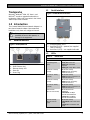
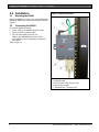
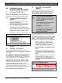
Conettix ITS-D6682-INTL
Installation Guide
EN
Ethernet Network
Adapter
Conettix ITS-D6682-INTL | Installation Guide | Contents
Contents
1.0
1.1
1.2
1.3
2.0
2.1
2.2
3.0
3.1
3.2
3.3
3.4
3.5
3.6
3.7
4.0
2
Introduction...................................................... 3
Network Interface.............................................. 3
Serial Interface.................................................. 3
LEDs ................................................................. 3
Installation........................................................ 4
Mounting the D6682.......................................... 4
Connecting the D6682 ...................................... 4
Configuring and Programming the D6682 .... 5
Factory Default IP Address ............................... 5
Identifying the MAC Hardware Address ............ 5
Obtaining an IP Address ................................... 5
Using ARP to Assign the IP Address ................ 5
ARP Command Usage...................................... 6
Using Telnet to Finish the Configuration ........... 7
Programming Overview for the D6600 ............ 10
Specifications ................................................ 11
Bosch Security Systems, Inc. | 2/09 | F01U126778-01
Conettix ITS-D6682-INTL | Installation Guide | 1.0 Introduction
.
Trademarks
Microsoft® Windows® 2000, XP, Vista™, and
MS-DOS®, are either registered trademarks or
trademarks of Microsoft Corporation in the United
States and/or other countries.
1.2
Serial Interface
Figure 2: D6682 Network Interface
1.0 Introduction
The Conettix D6682 Ethernet Network Adapter is a
two-channel network adapter. Most networked
installations only have one configured channel.
Follow these instructions to avoid the
possibility of harm to the operator, or
damage to the equipment.
1.1
Network Interface
Figure 1: Power/Ethernet
1- Power/Diagnostic LEDs
2- Serial Port 2 (DTE) – optional (use supplied
cable if required)
3- Serial Port 1 (DTE) – use supplied null cable
1.3
LEDs
Table 1:
12345-
Ethernet Link LED
RJ45 Ethernet Jack
Ethernet Activity LED
Reset Pin
Power Plug
D6682 LEDs
LED
Power/Diagnostic
(Blue)
RX Serial 1 Activity
(Green)
TX Serial 1 Activity
(Yellow)
RX Serial 2 Activity
(Green)
TX Serial 2 Activity
(Yellow)
Ethernet Link
(Bi-color LED on left)
Ethernet Activity
(Bi-color LED on
right)
Bosch Security Systems, Inc. | 2/09 | F01U126778-01
Description
Steady On: Power OK
Blinking 2x: No DHCP
response
Blinking 2x: Setup Menu active
Off: No data activity
Blinking: Data received by
D6682 on Channel 1
Off: No data activity
Blinking: Data transmitted from
D6682 on Channel 1
Off: No data activity
Blinking: Data received by
D6682 on Channel 2
Off: No data activity
Blinking: Data transmitted from
D6682 on Channel 2
Off: No Ethernet link
established
Solid Yellow: 10 Mbps
Ethernet link established
Solid Green: 100 Mbps
Ethernet link established
Off: No data activity
Solid Yellow: Half Duplex data
activity
Solid Green: Full Duplex data
activity
3
Conettix ITS-D6682-INTL | Installation Guide | 2.0 Installation
2.0 Installation
2.1
Figure 3: D6682 Connections
Mounting the D6682
Mount the D6682 on a rail or other user-supplied spot
behind the D6600 that it will be connected to. Refer to
Figure 3.
2.2
Connecting the D6682
Connect the D6682 as follows:
• Power cable to an available electrical outlet
• Ethernet cable to network switch
• RS-232 serial cable to Serial 1 port
Refer to the D6600/D6100i System Guide
(P/N: 4998122712) for applications using both
serial ports.
Refer to Figure 3.
1– Power cable
2– Ethernet cable
3– RS-232 serial cable (Serial 1 port)
4– Serial 2 port (empty)
5 – Standard 19-in. mounting rack
4
Bosch Security Systems, Inc. | 2/09 | F01U126778-01
Conettix ITS-D6682-INTL | Installation Guide | 3.0 Configuring and Programming the D6682
.
3.0 Configuring and
Programming the D6682
3.1
Factory Default IP Address
By default, the D6682 uses DHCP to obtain an IP
Address. The unit requires a static IP Address. Refer
to Sections 3.2, 3.3, and 3.4 for more information.
3.2
Identifying the MAC Hardware
Address
1. Verify that the D6682 is properly installed,
connected, and powered.
Refer to Section 2.0 Installation on page 4.
2. Locate the D6682’s media access control
(MAC), or hardware, address.
The MAC address is hard-coded into the
D6682 during manufacturing, and it cannot be
changed. This address is 6 bytes (12 digits)
in length and is located on a label on the
D6682 in the format of “xx-xx-xx-xx-xx-xx”.
Figure 4: MAC Address Location
1
1- MAC address location on D6682 label
3. Record the MAC address and keep it for
reference.
3.3
Obtaining an IP Address
Provide the D6682’s MAC address to the site’s
network administrator, who will assign an IP address
to the D6682.
An IP Address is an identifier for a computer or device
on a transmission control protocol/internet protocol
(TCP/IP) network. Networks use the TCP/IP protocol
route messages based on the IP address of the
destination. The format of an IP address is a 32-bit
numeric address written as four numbers or fields
separated by periods. Each number can be 0 to 255.
For example, 190.200.128.111 could be an IP
address. Within an isolated network, you can assign
IP addresses at random if each one is unique.
However, connecting a private network to the Internet
requires using registered IP addresses (called
Internet addresses) to avoid duplicates.
Bosch Security Systems, Inc. | 2/09 | F01U126778-01
3.4
Using ARP to Assign the IP
Address
Bosch Security Systems, Inc. recommends that you
read this entire section before proceeding. Also,
ensure that power is applied to the D6682 and the
Ethernet Network RJ45 connection is in place.
In order to access the configuration
program, ensure that the D6682 and the
PC used to configure it are on the same
gateway (the device that connects the
LAN to the WAN).
Use the telnet program to communicate
with the D6682 and establish its
communication configuration
parameters.
After the D6682 is configured and has
an IP address, you can change the
telnet configuration parameters from
anywhere on the network.
The D6200 Software is the recommended way to
program the network devices. If you choose to use
the software to program the network devices, review
Section 3.7 Programming Overview for the D6600 on
page 10, and the D6200 Programming Software
Operation and Installation Guide (P/N: 4998154991).
1. When you have the IP address, and the
network administrator confirms that it is
ready, open the MS-DOS prompt on the host
computer on the network to be used.
2. Use the address resolution protocol (ARP)
program to assign a new IP address for the
D6682.
ARP is a Windows-based program used to
create a temporary association between an
IP address and a hardware address, such as
a MAC.
3. Place the ARP program in the C:\WINDOWS
or C:\WINNT directory (depending on your
operating system) by default during the
installation of the operating system as shown
in Figure 5.
Figure 5: ARP Command Syntax
arp -s xxx.xxx.xxx.xxx zz-zz-zz-zz-zz-zz
1
2
1- IP Address assigned to the D6682
2- MAC Hardware Address from D6682 label
5
Conettix ITS-D6682-INTL | Installation Guide | 3.0 Configuring and Programming the D6682
3.5
ARP Command Usage
Perform the following procedure when using the ARP
command to assign an IP address to a D6682. The
MAC address shown below is used as an example.
00-20-4a-12-04-0e
3. Type the arp –s command with the IP
address and the MAC hardware address.
For this example the IP address is
190.220.128.219 and the MAC hardware
address is: 00-20-4a-01-b5-3d
The IP and MAC addresses used in this
example are not the same as the
numbers you are using. This procedure
is for demonstration only.
1. Select Start → Run to open an MS-DOS
window.
If the computer responds with the
C:\WINDOWS> prompt after you enter the
ARP command, the address is accepted.
Refer to Figure 6.
Figure 6: MS-DOS Prompt
2. At the Run dialog box, type COMMAND and
click OK.
There is no indication that the operation
is properly performed. The absence of
an error message is an indication that
the ARP command was successful.
A DOS window appears.
6
4. Type arp-g and press [ENTER] to verify that
the IP address was entered correctly:
arp -g [ENTER]
Bosch Security Systems, Inc. | 2/09 | F01U126778-01
Conettix ITS-D6682-INTL | Installation Guide | 3.0 Configuring and Programming the D6682
.
3.6
Using Telnet to Finish the
Configuration
Although the screen shots are specific
to Windows 2000, they are similar for
Windows XP and Vista.
In Windows Vista, Telnet is disabled by
default. In order to use Telnet, you must
enable it:
A DOS window appears:
1. Click Start→Control
Panel→Programs.
2. Click Turn Windows features on
or off.
If you are prompted for an
administrator password or
confirmation, type the password or
provide confirmation.
3. In the Windows Features dialog
box, select the Telnet Client check
box.
The colors are inverted here for clarity. The
normal prompt window appears with white
text on black.
7. At the C:\> prompt, type telnet and press
[ENTER].
4. Click OK.
The installation might take several
minutes.
To use Telnet, you must log in as a user
with Administrative privileges.
This example uses the IP address of
10.25.124.148 and the MAC Address of
00-20-4a-51-01-a7.
To complete the IP address configuration of the
D6682, launch a telnet session:
5. Select Start Æ Run to open an MS-DOS
window.
8. At the Microsoft Telnet> prompt, type open
(space) IP Address (space) Port Number.
Figure 7:Command Prompt - telnet
Example: open 190.220.128.219 1
The connection fails the first time. This is
normal.
9. Press [F3] to show the last line typed.
10. Backspace over the port value and change it
to 9999.
6. Type telnet and click OK.
Figure 8: Port Value Change
Example: open 190.220.128.219 9999
11. Press [ENTER].
Bosch Security Systems, Inc. | 2/09 | F01U126778-01
7
Conettix ITS-D6682-INTL | Installation Guide | 3.0 Configuring and Programming the D6682
12. If you pressed [ENTER] within five sec, you
should see the following screen.
Refer to Figure 9.
Figure 9: Telnet Session
15. When asked to set the Gateway IP address
(Figure 10), type N and press [ENTER] to
accept the default.
Figure 10: Telnet session – Gateway Address
The Gateway IP address is needed with
a wide area network (WAN). In a local
area network (LAN), the Gateway is
usually not needed.
13. Press [0] + [ENTER] to set up the basic
Server Configuration. You must enter the
desired IP address.
If the D6682 was already programmed with
an IP address, the address appears in
parentheses.
16. To change the Netmask from the default,
enter the number of bits that correspond to
the Netmask your network is using.
Refer to Table 2 on page 9).
See your network administrator for more
information.
17. Press [ENTER] after entering the correct
number of bits for the Netmask.
For example, if this D6682 was originally
programmed to IP address 190.200.128.152,
the address should be changed to
190.200.128.220.
14. To properly program IP Address
190.200.128.220, press the following keys:
[1][9][0][ENTER][2][0][0][ENTER][1][2][8]
[ENTER][2][2][0][ENTER]
The IP and MAC addresses used in this
example are not the same as the
numbers you are using. This procedure
is for demonstration only.
8
Bosch Security Systems, Inc. | 2/09 | F01U126778-01
Conettix ITS-D6682-INTL | Installation Guide | 3.0 Configuring and Programming the D6682
.
19. Press [1] [ENTER] to configure Channel 1.
Baudrate 9600 appears.
Table 2: Netmask Address
Number of Host Bits
1
2
3
4
5
6
7
8
9
10
11
12
13
14
15
16
17
18
19
20
21
22
23
24
25
26
27
28
29
30
31
Netmask
255.255.255.254
255.255.255.252
255.255.255.248
255.255.255.240
255.255.255.224
255.255.255.192
255.255.255.128
255.255.255.0
255.255.254.0
255.255.252.0
255.255.248.0
255.255.240.0
255.255.224.0
255.255.192.0
255.255.128.0
255.255.0.0
255.254.0.0
255.252.0.0
255.248.0.0
255.240.0.0
255.224.0.0
255.192.0.0
255.128.0.0
255.0.0.0
254.0.0.0
252.0.0.0
248.0.0.0
240.0.0.0
224.0.0.0
192.0.0.0
128.0.0.0
18. When you are prompted to change the telnet
password, press [N] for No (default setting).
The Setup Mode screen appears again.
Refer to Figure 9 on page 8.
If you use a password, store it in a
secure place. If the password is lost or
forgotten you cannot connect to the
telnet program on this unit again. The
unit must be returned to the factory and
reconditioned before it can receive
another telnet session.
Bosch Security Systems, Inc. | 2/09 | F01U126778-01
The D6682 must be set to a baud rate
of 38400.
20. Type 38400 and press [ENTER] to change
the baud rate.
I/F Mode (4C) ? appears.
21. Press [ENTER] to accept 4C (default setting)
as the entry.
If a different value appears in parentheses,
type 4C and press [ENTER] to change the
value.
Flow (00) ? appears.
22. Press [ENTER] to accept 00 (default setting)
as the entry.
If a different value appears in parentheses,
type 00 and press [ENTER] to change the
value.
Port No (13257) ? appears.
23. For the Port number, type a number between
2000 and 10000, and press [ENTER].
If using two channels, set different port
numbers for Channel 1 and Channel 2
(shown in the Telnet configuration
screen).
ConnectMode (CC) ? appears.
24. Press [ENTER] to accept CC (default setting)
as the entry, or type CC and press [ENTER]
to change the value.
Datagram Type (00) ? appears.
25. If all field devices are using the same port
number as entered in Step 23, type 00 and
press [ENTER].
To use Datagram Type 02, Bosch
firmware version 6.5.8.0 or later is
required. Refer to the Device Installer
Operation and Installation Guide
(P/N: 4998138688) for more
information.
26. If all field devices are using unique port
numbers, type 02 and press [ENTER].
If Datagram Type 02 is used, enable it
in the D6600 Receiver refer to the
D6600 Program Entry Guide
(P/N: 4998122702).
For more information on Datagram
Types, refer to the Conettix D6600
System Guide (P/N: 4998122712).
9
Conettix ITS-D6682-INTL | Installation Guide | 3.0 Configuring and Programming the D6682
27. If you want to enable encryption, select 6
Security from the main menu and continue
with Step 28.
If encryption is enabled on the D6682
(refer to Figure 11), you must enable it
on all field devices (C900TTL-E,
D9133TTL-E, DX4020) with the same
key. Encryption must also be enabled in
the D6600 Receiver. Refer to the D6600
Program Entry Guide (P/N:
4998122702).
The network interface module (D6682,
C900TTL-E, D9133TTL-E, or DX4020)
must have the proper software version
to support encryption. For more details,
refer to the Device Installer Operation
and Installation Guide (P/N:
4998138688).
Figure 11: D6682 Encryption
After you make all the changes and
verify them for accuracy, you must save
the information.
37. Select 9 – save and exit. When the
connection to host is lost, press [ENTER] to
continue.
3.7
Programming Overview for the
D6600
The D6600 Receiver is shipped with factory default
program parameters and features already installed.
Descriptions of the program items are found in the
D6600 Program Entry Guide (P/N: 4998122702).
Many of the operational features of the D6600 can be
altered through programming options. The
programming options you choose depend on:
• The type(s) of peripheral reporting device(s) used
in your central station (for example external
printer or automation computer)
• The supervision characteristics for these devices
• The type of communicators reporting to the
receiver
• The number and type of receiving lines in use
• Sending the files back to the D6600
(CPU/Host/Network, Account Database, or Line
Card)
• Upgrading the Software installed in the D6600
(CPU, System, or PSTN line cards)
Refer to the D6200 Software Operation and
Installation Guide (P/N: 4998154991) for information
and procedures on how to accomplish these tasks.
28. At Disable SNMP (N) N, press [ENTER].
29. At SNMP Community Name ( ):
press [ENTER].
30. At Disable Telnet Setup (N) N,
press [ENTER].
31. At Disable Port 77Feh (N) N, press
[ENTER].
32. At Disable Web Server (N) N,
press [ENTER].
33. At Disable ECHO ports (Y) Y,
press [ENTER].
34. At Enable Encryption (N), press [ENTER].
35. At Change keys (N), press [Y]. Enter keys as
follows:
- These 16 bytes (32 characters) should
match the bytes programmed in the
D6682.
Default value is 01-02-03-04-05-06-0708-09-10-11-12-13-14-15-16.
36. At Enable Enhanced Password (N),
press [ENTER].
-
10
Bosch Security Systems, Inc. | 2/09 | F01U126778-01
Conettix ITS-D6682-INTL | Installation Guide | 4.0 Specifications
.
4.0 Specifications
Table 3: Specifications
Supported
Protocols
Connectors
ARP, UDP/IP, TCP/IP, Telnet, ICMP, SNMP, DHCP, BOOTP, TFTP, and HTTP
Serial:
2 - DB9M DTE serial ports
Network:
1 - RJ45 10Base-T/100Base-TX Ethernet port
Cables
Ethernet:
Data Rates
Serial Line Formats
Modem Controls
Flow Control
Management
System Software
Diagnostic LEDs
Compatibility
AC Current
Required
Power Input
Environmental
CAT5 or better unshielded twisted pair
Max Length: 100 m (328 ft) and installed in same enclosure/rack as
D6600.
RS-232:
Max Length: 15 m (50 ft) and installed in same enclosure/rack as D6600.
Serial speed ranging from 300 bps to 115.2 kbps
Characters
Stop bits:
7 or 8 data bits
1 or 2
Parity:
Odd, even, none
DTR, DSR
Software: XON/XOFF
Hardware: CTS/RTS
HTTP (internal web server)
SNMP (read only)
Serial login
Telnet login
DeviceInstaller software
Flash ROM standard: downloadable from a TCP/IP host (TFTP) or over serial port
Power
10/100 Mb Link on RJ45, 10/100 Activity on RJ45
RX Serial 1 Activity, TX Serial 1 Activity, RX Serial 2 Activity, TX Serial 2 Activity
Ethernet: v2.0/IEEE 802.3
D6600
UPS Standby Current: 0.4 A
AC nominal operating range: 100 to 240 VAC, 50/60 Hz, 0.4A max
Operating Temperature:
Storage Temperature:
0° to 50° C (32° to 122° F)
-40° to 85° C (-40° to 185° F)
Dimensions (H x W x D):
Unit:
Weight
3.75 in. x 2.9 in. x .9 in. (9.5 cm x 7.3 cm x 2.3 mm)
0.6 lbs. (0.26 kg)
Bosch Security Systems, Inc. | 2/09 | F01U126778-01
11
Bosch Security Systems, Inc.
130 Perinton Parkway
Fairport, NY 14450-9199
(800) 289-0096
© 2009 Bosch Security Systems, Inc.
F01U126778-01