1
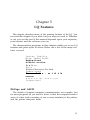
EPSON®
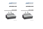
LQ-800 and LQ-1000 Printers
User's Manual
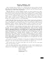
FCC COMPLIANCE STATEMENT
FOR AMERICAN USERS
This equipment generates and uses radio frequency energy and if not installed and used
properly, that is, in strict accordance with the manufacturer’s instructions, may cause
interference to radio and television reception. It has been type tested and found to comply
with the limits for a Class B computing device in accordance with the specifications in
Subpart J of part 15 of FCC Rules, which are designed to provide reasonable protection
against such interference in a residential installation. However, there is no guarantee that
interference will not occur in a particular installation. If this equipment does cause interference to radio or television reception, which can be determined by turning the equipment off and on, the user is encouraged to try to correct the interference by one or more of
the following measures:
- Reorient the receiving antenna
- Relocate the computer with respect to the receiver
- Plug the computer into a different outlet so that the computer and receiver are on
different branch circuits.
If necessary, the user should consult the dealer or an experienced radio/television technician for additional suggestions. The user may find the following booklet prepared by the
Federal Communications Commission helpful:
“How to Identify and Resolve Radio-TV Interference Problems.”
This booklet is available from the U.S. Government Printing Office, Washington, DC
20402. Stock No. 004-000-00345-4.
WARNING
The connection of a non-shielded printer interface cable to this printer will invalidate the FCC Certification of this device and may cause interference levels which
exceed the limits established by the FCC for this equipment. If this equipment has
more than one interface connector, do not leave cables connected to unused interfaces.
All rights reserved. No part of this publication may be reproduced, stored in a retrieval
system, or transmitted, in any form or by any means, mechanical, photocopying, recording or otherwise, without the prior written permission of Seiko Epson Corporation. No
patent liability is assumed with respect to the use of the information contained herein.
While every precaution has been taken in the preparation of this book, Seiko Epson
Corporation assumes no responsibility for errors or omissions. Neither is any liability
assumed for damages resulting from the use of the information contained herein.
Apple is a registered trademark of Apple Computer, Inc.
Applesoft is a trademark of Apple Computer, Inc.
Centronics is a registered trademark of Data Computer Corporation.
Epson is a registered trademark of Seiko Epson Corporation.
IBM is a registered trademark of International Business Machines Corporation.
Microsoft is a trademark of Microsoft Corporation.
QX-IO is a registered trademark, and QX is a trademark of Epson America, Inc.
Copyright © 1985 by Seiko Epson Corporation
Nagano, Japan
ii
Contents
Introduction . . . . . . . . . . . . . . . . . . . . . . . . . . . . . . . . . . . Intro-1
1
2
Setting Up Your LQ Printer . . . . . . . . . . . . . . . . . . . . .
1-1
Unpacking Your Printer . . . . . . . . . . . . . . . . . . . . . . . .
Installing the paper feed knob . . . . . . . . . . . . . . . . .
Selecting the Right Location . . . . . . . . . . . . . . . . . . . . .
Installing the Ribbon . . . . . . . . . . . . . . . . . . . . . . . . . . .
Replacing the ribbon . . . . . . . . . . . . . . . . . . . . . . . .
Loading Single-Sheet Paper . . . . . . . . . . . . . . . . . . . . .
Installing the single-sheet guide . . . . . . . . . . . . . . . .
Loading the paper . . . . . . . . . . . . . . . . . . . . . . . . . . .
Adjusting the paper thickness lever . . . . . . . . . . . . .
Turning On the Power . . . . . . . . . . . . . . . . . . . . . . . . .
Operating the Control Panel . . . . . . . . . . . . . . . . . . . .
OFF LINE/ON LINE . . . . . . . . . . . . . . . . . . . . . . . . .
FORM FEED/LETTER QUALITY . . . . . . . . . . . . . .
LINE FEED/DRAFT . . . . . . . . . . . . . . . . . . . . . . . . .
Selecting the Letter Quality or Draft Mode . . . . . . . . .
Running the Self Test . . . . . . . . . . . . . . . . . . . . . . . . . . .
Connecting Your Printer to Your Computer . . . . . . . .
The parallel interface . . . . . . . . . . . . . . . . . . . . . . . . .
The serial interface . . . . . . . . . . . . . . . . . . . . . . . . . . .
Printing Your First Document . . . . . . . . . . . . . . . . . . . .
1-1
1-3
1-4
1-5
1-8
1-8
1-8
1-9
1-12
1-12
1-14
1-14
1-15
1-15
1-16
1-16
1-17
1-18
1-18
1-19
The Cut Sheet Feeder . . . . . . . . . . . . . . . . . . . . . . . . . .
2-1
2-1
2-5
2-6
Installing the Cut Sheet Feeder . . . . . . . . . . . . . . . . . . .
Preparing the Paper for Loading . . . . . . . . . . . . . . . . .
Loading Paper . . . . . . . . . . . . . . . . . . . . . . . . . . . . . . . .
Setting up your word processor for a cut sheet
feeder . . . . . . . . . . . . . . . . . . . . . . . . . . . . . . . . . . .
Printing with the Cut Sheet Feeder . . . . . . . . . . . . . . . .
Removing the Cut Sheet Feeder . . . . . . . . . . . . . . . . . .
Troubleshooting . . . . . . . . . . . . . . . . . . . . . . . . . . . . . . .
Maintenance . . . . . . . . . . . . . . . . . . . . . . . . . . . . . . . . . .
2-8
2-9
2-10
2-12
2-13
iii
The Tractor Unit . . . . . . . . . . . . . . . . . . . . . . . . . . . . . .
Setting Up the LQ for Continuous-feed Paper . . . . . .
Installing the Tractor Unit . . . . . . . . . . . . . . . . . . . . . . .
Loading Paper . . . . . . . . . . . . . . . . . . . . . . . . . . . . . . . .
Setting the top-of-page position . . . . . . . . . . . . . . .
Installing the paper separator and tractor cover . . .
Removing the Optional Tractor Unit . . . . . . . . . . . . . .
3-1
3-1
3-2
3-3
3-8
3-8
3-11
4
Using the LQ with Commercial Software . . . . . . . . . .
4-1
5
LQ Features . . . . . . . . . . . . . . . . . . . . . . . . . . . . . . . . . .
3
ESCape and ASCII . . . . . . . . . . . . . . . . . . . . . . . . . . . .
Demonstration Programs . . . . . . . . . . . . . . . . . . . . . . .
Running BASIC programs . . . . . . . . . . . . . . . . . . . .
Sending Control Codes to the Printer . . . . . . . . . . . . .
Basic Widths . . . . . . . . . . . . . . . . . . . . . . . . . . . . . . . . . .
Pica printing . . . . . . . . . . . . . . . . . . . . . . . . . . . . . . . .
Elite printing . . . . . . . . . . . . . . . . . . . . . . . . . . . . . . . .
Fifteen mode printing . . . . . . . . . . . . . . . . . . . . . . . .
Letter Quality and Draft . . . . . . . . . . . . . . . . . . . . . . . .
Cancelling Modes . . . . . . . . . . . . . . . . . . . . . . . . . . . . .
Resetting the Printer . . . . . . . . . . . . . . . . . . . . . . . . . . .
Disabling a program’s reset code . . . . . . . . . . . . . . .
Print Quality Command . . . . . . . . . . . . . . . . . . . . . . . .
Other Widths . . . . . . . . . . . . . . . . . . . . . . . . . . . . . . . . .
Double-width printing . . . . . . . . . . . . . . . . . . . . . . . .
Condensed printing . . . . . . . . . . . . . . . . . . . . . . . . . .
Print Enhancements . . . . . . . . . . . . . . . . . . . . . . . . . . . .
Emphasized mode . . . . . . . . . . . . . . . . . . . . . . . . . . .
Double-strike . . . . . . . . . . . . . . . . . . . . . . . . . . . . . . .
Underline mode . . . . . . . . . . . . . . . . . . . . . . . . . . . . .
Proportional mode . . . . . . . . . . . . . . . . . . . . . . . . . .
Master Select . . . . . . . . . . . . . . . . . . . . . . . . . . . . . . .
Superscript and subscript . . . . . . . . . . . . . . . . . . . . .
International characters . . . . . . . . . . . . . . . . . . . . . . .
Page Formatting . . . . . . . . . . . . . . . . . . . . . . . . . . . . . . .
Margins . . . . . . . . . . . . . . . . . . . . . . . . . . . . . . . . . . .
Skip-over-perforation . . . . . . . . . . . . . . . . . . . . . . . .
Linespacing . . . . . . . . . . . . . . . . . . . . . . . . . . . . . . . .
Half-Speed Mode . . . . . . . . . . . . . . . . . . . . . . . . . . . . . .
Printing to the End of the Page . . . . . . . . . . . . . . . . . .
iv
5-1
5-1
5-2
5-3
5-4
5-5
5-5
5-5
5-5
5-6
5-6
5-6
5-7
5-8
5-8
5-8
5-9
5-10
5-10
5-11
5-12
5-12
5-13
5-15
5-15
5-18
5-18
5-19
5-19
5-20
5-20
6
Graphics and User-Defined Characters . . . . . . . . . . . .
Graphics . . . . . . . . . . . . . . . . . . . . . . . . . . . . . . . . . . . . .
The print head . . . . . . . . . . . . . . . . . . . . . . . . . . . . . .
Dot patterns . . . . . . . . . . . . . . . . . . . . . . . . . . . . . . . .
Eight-pin graphics . . . . . . . . . . . . . . . . . . . . . . . . . . .
Twenty-four-pin graphics . . . . . . . . . . . . . . . . . . . . .
Pin labels . . . . . . . . . . . . . . . . . . . . . . . . . . . . . . . . .
Graphics Command . . . . . . . . . . . . . . . . . . . . . . . . . . .
Column reservation numbers . . . . . . . . . . . . . . . . . .
First graphics program . . . . . . . . . . . . . . . . . . . . . . .
Using hand-calculated data to print graphics . . . . .
Individual graphics options commands . . . . . . . . . .
Reassigning command . . . . . . . . . . . . . . . . . . . . . . . .
User-Defined Characters . . . . . . . . . . . . . . . . . . . . . . . .
Design grids . . . . . . . . . . . . . . . . . . . . . . . . . . . . . . . .
Defining Your Own Characters . . . . . . . . . . . . . . . . . .
Data numbers . . . . . . . . . . . . . . . . . . . . . . . . . . . . . .
Sending information to the LQ . . . . . . . . . . . . . . . .
Printing User-Defined Characters . . . . . . . . . . . . . . . . .
Copying ROM to RAM . . . . . . . . . . . . . . . . . . . . . .
Letter Quality characters . . . . . . . . . . . . . . . . . . . . . .
Proportional mode characters . . . . . . . . . . . . . . . . .
Superscripts and subscripts . . . . . . . . . . . . . . . . . . . .
Mixing print styles . . . . . . . . . . . . . . . . . . . . . . . . . . .
6-1
6-1
6-2
6-3
6-3
6-3
6-3
6-5
6-6
6-6
6-7
6-10
6-10
6-11
6-11
6-13
6-13
6-14
6-16
6-17
6-18
6-18
6-18
6-19
V
Appendixes
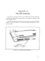
A
The DIP Switches . . . . . . . . . . . . . . . . . . . . . . . . . . . . .
A-1
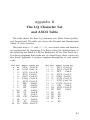
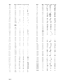
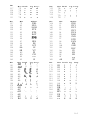
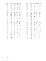
B
The LQ Character Set and ASCII Table . . . . . . . . . . .
B-1
Installing the Option Cartridge . . . . . . . . . . . . . . . . . . .
C-1
C-2
C-3
C-3
D
Troubleshooting and Maintenance . . . . . . . . . . . . . . . .
Diagnosing the Problem . . . . . . . . . . . . . . . . . . . . . . . .
Beeper Error Warnings . . . . . . . . . . . . . . . . . . . . . . . . .
Hex Dump Mode . . . . . . . . . . . . . . . . . . . . . . . . . . . . . .
IBM PC BASIC Solutions . . . . . . . . . . . . . . . . . . . . . . .
Applesoft BASIC Solutions . . . . . . . . . . . . . . . . . . . . .
QX-10 and QX-16 Solutions . . . . . . . . . . . . . . . . . . . . .
Maintenance . . . . . . . . . . . . . . . . . . . . . . . . . . . . . . . . . .
Changing the print head . . . . . . . . . . . . . . . . . . . . . .
D-1
D-1
D-4
D-4
D-6
D-7
D-8
D-8
D-8
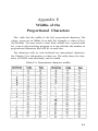
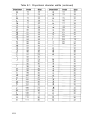
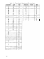
E
Widths of the Proportional Characters . . . . . . . . . . . .
E-1
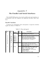
F
The Parallel and Serial Interfaces . . . . . . . . . . . . . . . . .
F-1
G
Choosing and Setting Up Optional Interfaces . . . . . . .
G-1
H
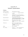
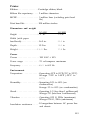
Technical Specifications . . . . . . . . . . . . . . . . . . . . . . . . .
H-1
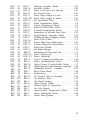
I
Command Summary . . . . . . . . . . . . . . . . . . . . . . . . . . .
I-1
C
The Identity Module . . . . . . . . . . . . . . . . . . . . . . . . . . .
The Font Module . . . . . . . . . . . . . . . . . . . . . . . . . . . . . .
Using the Option Cartridges . . . . . . . . . . . . . . . . . . . . .
Index . . . . . . . . . . . . . . . . . . . . . . . . . . . . . . . . . . . . . . . . . Index-1
vi
Figures
1-1
1-2
1-3
1-4
1-5
1-6
1-7
1-8
1-9
1-10
1-11
1-12
1-13
1-14
The
LQ-800 . . . . . . . . . . . . . . . . . . . . . . . . . . . . . . .
The LQ-1000 . . . . . . . . . . . . . . . . . . . . . . . . . . . . . .
Installing the paper feed knob . . . . . . . . . . . . . . . .
Tightening the ribbon . . . . . . . . . . . . . . . . . . . . . . .
Loading the LQ-800 ribbon cartridge . . . . . . . . . .
Loading the LQ-1000 ribbon cartridge . . . . . . . . .
Positioning the ribbon . . . . . . . . . . . . . . . . . . . . . .
Installing the single-sheet guide . . . . . . . . . . . . . . .
Loading single-sheet paper . . . . . . . . . . . . . . . . . . .
Paper thickness lever . . . . . . . . . . . . . . . . . . . . . . .
Turning on the power switch . . . . . . . . . . . . . . . . .
The LQ control panel . . . . . . . . . . . . . . . . . . . . . . .
LQ self test in draft and Letter Quality modes . . .
Connecting a parallel interface cable . . . . . . . . . . .
1-2
1-2
1-3
1-5
1-6
1-6
1-7
1-9
1-10
1-12
1-13
1-14
1-17
1-18
2-1
2-2
2-3
2-4
2-5
2-6
2-7
2-8
2-9
Preparing the printer for installation . . . . . . . . . . .
Installing the cut sheet feeder . . . . . . . . . . . . . . . . .
Installing the small brackets . . . . . . . . . . . . . . . . . .
Installing the large bracket . . . . . . . . . . . . . . . . . . .
The LQ-1000 model . . . . . . . . . . . . . . . . . . . . . . . .
Paper support and paper loading lever . . . . . . . . .
Loading paper; adjusting the right paper guide . .
Turning the power on . . . . . . . . . . . . . . . . . . . . . . .
Removing the cut sheet feeder . . . . . . . . . . . . . . . .
2-1
2-2
2-3
2-4
2-5
2-6
2-7
2-9
2-11
3-1
3-2
3-3
3-4
3-5
3-6
3-7
3-8
3-9
3-10
3-11
3-12
3-13
Continuous-feed paper with printer stand . . . . . .
Continuous-feed paper without stand . . . . . . . . . .
Installing the tractor unit . . . . . . . . . . . . . . . . . . . .
Preparing for paper loading . . . . . . . . . . . . . . . . . .
Moving the pin-feed holders . . . . . . . . . . . . . . . . .
Opening the pin-feed covers . . . . . . . . . . . . . . . . . .
Installing the paper shelf . . . . . . . . . . . . . . . . . . . . .
Loading paper . . . . . . . . . . . . . . . . . . . . . . . . . . . . .
Fitting the paper over the pin feeds . . . . . . . . . . . .
Top-of-page position . . . . . . . . . . . . . . . . . . . . . . . .
Installing the paper separator . . . . . . . . . . . . . . . . .
Installing the tractor cover . . . . . . . . . . . . . . . . . . .
Removing the optional tractor unit . . . . . . . . . . . .
3-1
3-2
3-2
3-3
3-4
3-5
3-5
3-6
3-7
3-8
3-9
3-10
3-11
vii
6-1
6-2
6-3
6-4
6-5
6-6
6-7
6-8
Pin numbering system . . . . . . . . . . . . . . . . . . . . . .
Calculations for pin patterns . . . . . . . . . . . . . . . . .
Pattern on grid . . . . . . . . . . . . . . . . . . . . . . . . . . . .
Data layout for 24-pin graphics . . . . . . . . . . . . . . .
Design grids . . . . . . . . . . . . . . . . . . . . . . . . . . . . . . .
User-defined character . . . . . . . . . . . . . . . . . . . . . .
Calculating the data . . . . . . . . . . . . . . . . . . . . . . . .
Grids for super/subscript characters . . . . . . . . . . .
6-12
6-13
6-14
6-19
A-1
The DIP switch panels . . . . . . . . . . . . . . . . . . . . . .
A-1
Plugging the identity and font
modules together . . . . . . . . . . . . . . . . . . . . . . . . .
Installing an option cartridge . . . . . . . . . . . . . . . . .
C-1
C-2
D-1
D-2
Print head replacement . . . . . . . . . . . . . . . . . . . . . .
Removing the ribbon cables . . . . . . . . . . . . . . . . . .
D-9
D-10
F-1
Parallel interface timing . . . . . . . . . . . . . . . . . . . . .
F-3
G-1
G-2
G-3
G-4
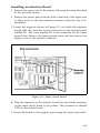
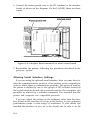
Removing the upper case . . . . . . . . . . . . . . . . . . . .
Removing the control panel . . . . . . . . . . . . . . . . . .
Main circuit board . . . . . . . . . . . . . . . . . . . . . . . . .
Interface board mounted on main circuit board . .
G-3
G-4
G-5
G-6
C-1
C-2
viii
6-4
6-4
6-7
6-8
Tables
5-1
5-2
5-3
5-4
5-5
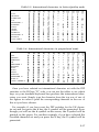
LQ character widths . . . . . . . . . . . . . . . . . . . . . . . .
International characters in Letter Quality mode . .
International characters in draft mode . . . . . . . . .
International characters in proportional mode . . .
Maximum right margin settings . . . . . . . . . . . . . . .
5-10
5-16
5-17
5-17
5-19
6-1
6-2
6-3
6-4
Graphics options . . . . . . . . . . . . . . . . . . . . . . . . . . .
Individual graphics options commands . . . . . . . . .
Character width limits . . . . . . . . . . . . . . . . . . . . . .
Super/subscript widths . . . . . . . . . . . . . . . . . . . . . .
6-5
6-10
6-15
6-19
A-1
A-2
A-3
A-4
A-5
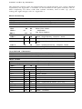
DIP switch panel 1 .........................
DIP switch panel 2 .........................
International DIP switch settings . . . . . . . . . . . . . .
Interface selection . . . . . . . . . . . . . . . . . . . . . . . . . .
Baud rate selection . . . . . . . . . . . . . . . . . . . . . . . . .
A-3
A-4
A-5
A-5
A-5
C-1
Print styles . . . . . . . . . . . . . . . . . . . . . . . . . . . . . . . .
c-2
E-1
Proportional character widths . . . . . . . . . . . . . . . .
E-1
F-1
F-2
F-1
F-3
Pins and signals . . . . . . . . . . . . . . . . . . . . . . . . . . . .
Printing enabled/disabled signals and control
conditions . . . . . . . . . . . . . . . . . . . . . . . . . . . . . .
Pins and signals . . . . . . . . . . . . . . . . . . . . . . . . . . . .
G-1
G-2
G-3
G-4
G-5
G-6
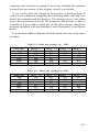
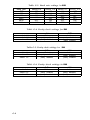
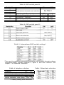
Baud rate settings for 8143 ...................
Baud rate settings for 8148 ...................
Baud rate settings for 8149 ...................
Parity check settings for 8143 ................
Parity check settings for 8148 ................
Parity check settings for 8149 ................
G-7
G-7
G-8
G-8
G-8
G-8
F-4
F-5
ix
Introduction
The Epson LQ-800 and LQ-1000 are state-of-the-art, X-pin dotmatrix printers that deliver exceptional speed and sharpness in either
Letter Quality or draft style.
The LQ-800 and LQ-1000 are also capable of a wide variety of print
enhancements, including:
LETTER
QUALITY
Bold
Italic
Underlining
S u b s c r i p t
S u p e r s c r i p t
D o u b l e - w i d t h
DRAFT
Bold
Italic
Underlining
S u b s c r i p t
S u p e r s c r i p t
D o u b l e
w i d t h
The LQ-800 and LQ-1000 combine the versatility and reliability of
Epson products, with a wide range of exciting new features.
l
l
l
l
You can select either the Letter Quality or draft typestyle with a
touch of a front panel button-there are no codes to learn.
The 24-pin print head produces sharp, crisp draft characters, and
Letter Quality characters that look like they came from a typewriter.
The LQ has built-in connectors for both parallel and serial interface
cables, so there’s no need for extra options or modifications.
Option cartridges are available to further extend the capabilities of
the LQ-800 and LQ-1000. These cartridges provide additional type
fonts, and will also allow you to use programs designed for other
popular printers.
Intro-1
l
l
The compact design and light weight of the LQ make it ideal for
home and business applications.
A 7K buffer frees your computer so you can work on one document
while printing another.
Using this manual
To make it easier to set up your new LQ-800 or LQ-1000, this manual includes a 10-step guide to setting up your printer. These steps take
you from unpacking, through ribbon and paper loading, to printing
your first document.
Easy-to-read tabs make it simple for beginners or experienced users
to find information. Additional sections describe how to use your new
printer with word processors, create graphics, define your own characters, and more.
If you are familiar with earlier Epson manuals, you’ll find two terms
changed to make them more descriptive. In this manual, doublewidth is used instead of expanded, and condensed is used in place of
compressed.
Intro-2
Chapter 1
Setting Up Your LQ Printer
Setting up your new LQ is easy. Simply follow the steps in this
chapter.
Note
The LQ-800 and LQ-1000 are essentially the same printer
except that the LQ-1000 can accept wider paper. Therefore,
most of the illustrations in this manual show only the LQ-800.
If there is a difference that you need to know about, a separate
illustration shows the LQ-1000.
1
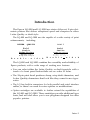
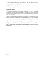
Unpacking Your Printer
First, remove the printer from the box and take off all outside
plastic covering and foam supports. See that you have received all the
parts shown in the illustrations on the next page. (You’ll find the paper
feed knob inserted in the foam packing material.)
1-1
Figure 1-1. The LQ-800
Figure 1-2. The LQ-1000
1-2
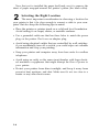
Remove the tape that holds the dust cover in place during shipping
and take the cover off the printer. Simply tilt the dust cover up and lift
it off the printer.
WARNING
The print head is protected by two plastic bumpers during shipping.
Both of these bumpers must be removed before turning on the printer.
Remove the long bumper to the right of the print head first, then move
the print head to the center of the LQ and remove the small bumper
on the left side of the print head.
There is a clear plastic overlay on the control panel to protect it
from scratching and discoloration. It’s up to you whether you remove
the overlay or leave it on.
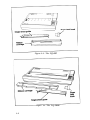
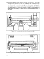
Installing the paper feed knob
Next install the paper feed knob. To install the knob, simply push it
onto the shaft on the right side of the printer, as shown in Figure 1-3.
The shaft has one flat side that must be matched with the flat side of
the hole in the knob.
Figure 1-3. Installing the paper feed knob
1-3
Now that you’ve installed the paper feed knob, use it to remove the
sheet of paper wrapped around the printer’s platen (the black roller).
2
Selecting the Right Location
The most important consideration in choosing a location for
your printer is that it be close enough to connect a cable to your computer. But also keep the following tips in mind:
l
l
l
l
l
l
Place the printer or printer stand on a solid and level foundation.
Avoid setting it on carpet, chairs, or unstable surfaces.
Use a grounded outlet-one that has three holes to match the power
plug on the printer. Don’t use an adapter plug.
Avoid using electrical outlets that are controlled by wall switchesif you accidentally turn off a switch, you could wipe out valuable
information and stop your printing.
Keep your printer and computer away from base units for cordless
telephones.
Avoid using an outlet on the same circuit breaker with large electrical machines or appliances that might disrupt the flow of power to
your printer.
Protect your printer from direct sunlight, and keep it away from
excessive heat, moisture, and dust. Make sure it’s not too close to a
heater or any other heat source.
1-4
3
Installing the Ribbon
With the dust cover removed, you have easy access to the
printer for ribbon installation and paper loading. The next time you
install a ribbon or load paper, you can leave the cover on.
Now you’re ready to install the ribbon.
1. Manually move the print head to the middle of the platen.
WARNING
The power must be OFF when moving the print head. Moving
the print head when the power is ON may damage your
printer. If you’ve been using your printer just before changing
the ribbon cartridge, be careful not to touch the print head
because it becomes hot during use.
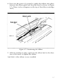
2. Before loading the cartridge into the printer, turn the small knob on
top in the direction of the arrow to tighten the ribbon as shown in
Figure 1-4.
Figure 1-4. Tightening the ribbon
1-5
3. For the LQ-800, hold the ribbon cartridge by the raised plastic fin
on top of the cartridge; for the LQ-1000 hold the cartridge by the
two plastic tabs. Lower the cartridge into the printer, guiding the
two square pins on each. end of the cartridge into the slots in
the printer frame, as shown in Figures 1-5 and 1-6. Press firmly on
each end of the cartridge to make sure the pins are firmly seated in
the slots.
Figure 1-5. Loading the LQ-800 ribbon cartridge
Figure 1-6. Loading the LQ-1000 ribbon cartridge
1-6
4. Now use the point of a pencil to guide the ribbon into place
between the ribbon guide and the print head as shown in Figure
1-7. (There is also a diagram on the top of the ribbon cartridge
itself.)
Figure 1-7. Positioning the ribbon
5. With the cartridge in place, again turn the ribbon knob in the direction of the arrow to tighten the ribbon.
And that’s it-the ribbon is now installed.
1-7
Replacing the ribbon. . .
When buying new ribbon cartridges for the LQ-800 or 1000, be sure
you get a ribbon specifically for the LQ-800 or 1000. Ribbon cartridges
for other Epson printers, such as the FX series, may closely resemble
an LQ ribbon, but their use can damage the LQ print head. Also,
ribbon cartridges for the LQ-1500 will not fit the LQ-800 or 1000, and
the Epson ribbon replacement pack #8758 should not be used as a
replacement ribbon.
The LQ uses a continuous-loop, inked fabric ribbon. When your
printing becomes too light, replace the ribbon with a fresh cartridge.
To replace the ribbon, just pull up on the raised fin on top of the
LQ-800 cartridge, or the two plastic tabs on the LQ-1000 and lift the
cartridge out of the printer. To install a new ribbon, follow the preceding steps.
4
Loading Single-Sheet Paper
When you receive your LQ, it is set up to print on single sheets
of paper. Even if you have purchased one of the optional paper feeding systems (the cut sheet feeder or the tractor unit), you should first
complete the remaining setup steps before installing either of the
optional systems.
It is much easier to run the self test (Step 8) and to connect the LQ to
your computer (Step 9) before you install an optional system. After
completing the setup steps, see Chapter 2 for installing the cut sheet
feeder, or Chapter 3 for installing the tractor unit.
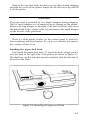
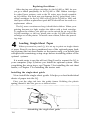
Installing the single-sheet guide
Now install the single-sheet guide. It helps you feed individual
sheets of paper into the LQ.
First, put the edge tab into the guide frame. Holding the plastic
spring, insert it into the groove as shown below.
Assembling the single-sheet guide
1-8
The guide has rounded pins on each end. These pins fit into notches
on each end of the paper slot.
Slide one of the guide’s pins into one notch. Then, with gentle pressure, snap the other pin into the other notch as shown in Figure 1-8.
Figure 1-8. Installing the single-sheet guide
The edge tab on the left side of the guide is movable, with a click
stop for its middle position. For standard-sized (8½-inch wide) paper,
see that the tab is in the click-stop position.
Loading the paper
Loading single-sheet paper in the LQ is simple-it’s just like loading
paper in a typewriter.
1-9
1. Check that the dust cover is tilted up to make it easier to see inside
the printer, as shown in Figure 1-9.
2. Make sure the paper release lever is pushed back in the direction of
the arrow in the figure, and that the paper bail is pulled away from
the platen.
Figure 1-9. Loading single-sheet paper
3. Insert a single sheet of paper behind the platen as shown in Figure
1-9. Put the left edge of the paper against the edge tab on the single
sheet guide.
4. With the power OFF use the paper feed knob to roll the paper into
the printer far enough to be held by the paper bail. (If the power is
ON, use the LINE FEED button as described in Step 6.)
5. Push the paper bail back against the paper, and the paper is ready.
1-10
Caution
Never use the manual paper feed knob while the power is ON
because you can damage the paper feed motor. Always use
the LINE FEED or FORM FEED button. You will also find that
the paper feed knob turns easily when the power is OFF, but is
difficult to turn while the power is ON.
When loading single-sheet paper, you may find that the LQ finishes
pages at different places than your word processor or applications
program does.
To ensure that your word processor and the LQ finish pages at the
same point:
1. Print out a page on the LQ. Check that the LQ and your word
processor have the same page length. If they differ, note how many
lines they differ by. For example, if your word processor is set up to
print 55 lines, but the LQ only prints 53 lines before ejecting the
page, there is a difference of two lines.
2. You now have three choices:
a) Compensate for the two-line difference when rolling the paper
into the printer.
b) Use the installation procedure on your word processor to
change the default page length.
c) Use commands in your word processing program to alter the
page or margin lengths in each file to accommodate the LQ’s
page length.
3. Once you’ve established the best settings, always load the paper so
that your printer starts at the same place on each page. For example, you may find that when you roll the paper one inch above the
print head, the page finishes where you want it to-then each time
you load paper, load it the same way.
With single-sheet paper, the key to consistent page formatting is to
establish the settings that work best for you, then position the paper in
the same place every time.
1-11
Adjusting the paper thickness lever
The LQ is equipped with a paper thickness lever that can be
adjusted to accommodate varying thicknesses of paper.
The lever is located in front of the paper release lever on the left side
of the printer as shown in Figure 1-10.
Figure 1-10. Paper thickness lever
When you receive your LQ, the lever is set for standard paper thickness (about 1/500th of an inch), with the small arm on the paper thickness lever set in the notch shown in Figure 1-10.
For thicker paper or multiple copies, pull the lever toward the front
of the printer. To return the lever to the standard position, push it back
until it clicks into the standard setting.
5
Turning On the Power
With the ribbon and paper installed in the LQ, it’s time to turn
the printer on and become acquainted with the power-up sequence.
1-12
Plug in the printer’s power cord, making sure the outlet is properly
grounded. Turn the power ON with the switch on the left side of the
printer (see Figure 1-11).
Figure 1-11. Turning on the power switch
When the power is turned ON:
l
l
l
The print head moves back and forth and stops at the left side of the
printer.
The printer is initialized-any previous settings are erased, and the
printer is reset to its default (or preset) values. See Appendix I for a
list of default values.
The three green lights on the control panel--POWER, READY, and
ON LINE-go on. (The red PAPER OUT light does not go on unless
the printer is out of paper.)
1-13
6
Operating the Control Panel
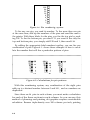
Each of the three buttons on the LQ control panel (see Figure
1-12) has two functions-the functions marked in blue (ON LINE,
LETTER QUALITY, and DRAFT) are active when the printer is on
line; the functions marked in black (OFF LINE, FORM FEED, and
LINE FEED) are active when the printer is off line. The printer is on
line when the ON LINE light is on; it is off line when the ON LINE
light is off.
Figure 1-12. The LQ control panel
OFF LINE/ON LINE
OFF LINE--If you press this button when the green light beside it is
on, the ON LINE and READY lights go off, the print head moves to
the center of the platen, and the printer is set off line-the power is still
on but the LQ won’t print. This enables the form feed and line feed
functions to work.
1-14
ON LINE-The green ON LINE light indicates that the printer is on
line and ready to receive data. When the LQ is on line, you can select
either the Letter Quality or draft mode.
FORM FEED/LETTER QUALITY
FORM FEED-Pressing this button advances the paper to the top of
the next page if you’re using continuous-feed paper (see Chapter 3,
“Installing the Tractor Unit”). If you’re using single-sheet paper, it fully
ejects one sheet. The form feed function works only when the printer
is off line.
LETTER QUALITY-Pressing this button selects the Letter Quality
typestyle (for more information on Letter Quality, see Step 7). The
printer beeps twice to acknowledge the Letter Quality selection. You
can select the Letter Quality typestyle with this button only when the
printer is on line.
LINE FEED/DRAFT
LINE FEED-Pressing this button advances the paper one line at a
time, either while you’re loading paper, or when you’re adjusting
where you want printing to begin. If you hold this button down, the
paper advances continuously. The line feed function works only when
the printer is off line.
DRAFT-Pressing this button selects the draft typestyle. The printer
beeps once to acknowledge the draft selection. The draft function
works only when the printer is on line.
Note
Use the LETTER QUALITY or DRAFT buttons before you
tell the computer to print. Do not use them while the LQ is
printing.
1-15
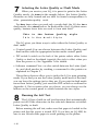
7
Selecting the Letter Quality or Draft Mode
When you receive your LQ, it is preset to print in the Letter
Quality mode. As shown in the sample below, the Letter Quality
characters are fully formed and are ideal for formal correspondence or
other presentation-quality work.
For those times when you need only a rough draft, the LQ also has a
draft mode, also shown below. In draft mode, the LQ prints more
quickly, because fewer dots are used to form each letter.
This
is
T h i s
i s
the
t h e
Letter
d r a f t
Quality
style
S t y l e
The LQ gives you three ways to select either the Letter Quality or
draft mode.
l
l
l
Control panel-You can choose between the Letter Quality and
draft modes with the appropriate button on the control panel.
DIP switch-A switch on the back of the printer selects either Letter
Quality or draft as the default typestyle (the style in effect when you
turn the power on). See Appendix A for details.
Software command-You can also switch between the Letter Quality and draft modes by sending a command to the printer as
explained in Chapter 5.
These three choices allow you to tailor the LQ to your printing
needs. If you find you use the Letter Quality mode most of the time,
you can leave the settings just as they are. If you print in draft mode
more than Letter Quality, just reset the DIP switch as outlined in
Appendix A. But no matter what you choose, you can always use the
buttons on the control panel to switch between the two styles.
8
Running the Self Test
The LQ has a built-in self test function that automatically
prints out all of the characters in the selected character set-either
Letter Quality or draft.
Before running the self test, make sure that paper is loaded in the
printer and that the power is turned OFF. If you have an LQ-1000, be
sure to use 14-inch-wide paper to avoid printing on the platen.
1-16
To run the self test in the Letter Quality mode, hold down the
LETTER QUALITY button while you turn the power switch ON. To
run the test in the draft mode, hold down the DRAFT button while
turning the power ON. The self test then takes over.
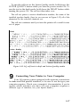
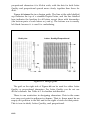
The self test prints a version identification number, the name of the
installed typeface family, then (as you can see in Figure 1-13) all of the
characters in the selected character set.
The self test continues until you turn the printer off or until it runs
out of paper.
Draft
Letter Quality
Figure 1-13. LQ self test in draft and Letter Quality modes
9
Connecting Your Printer to Your Computer
Your LQ printer comes equipped with separate connections
for both serial and parallel interfaces, so be sure to use the type your
computer requires. Check your computer’s documentation if you’re
unsure which interface you have. (If your computer requires a
different type of interface, see your Epson dealer.)
1-17
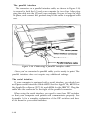
The parallel interface
The connector on a parallel interface cable, as shown in Figure 1-14,
is secured to both the LQ and your computer by two clips. After plugging the cable into the LQ and your computer, be sure to snap the clips
in place, and connect the ground strap if the cable is equipped with
one.
Figure 1-14. Connecting a parallel interface cable
Once you’ve connected a parallel cable, you’re ready to print. The
parallel interface does not require any additional settings.
The serial interface
If your computer is equipped with a serial interface, you should use
an Epson serial interface cable-#8239 for the Apple® IIc, #8293 for
the Apple IIe or Epson QX™-16, and #8294 for the IBM® PC. Plug the
cable into the connector to the right of the parallel connector.
When using the serial interface, you need to reset four DIP switches
so that your computer and printer will communicate properly. See
Appendix A for a complete explanation of the DIP switches and how
to set them for your serial interface.
1-18
10
Printing Your First Document
Now that you’ve completed the basic setup and operating steps, your LQ is ready to print. The following chapter explains
how to set up your word processor to work with the LQ.
Additional chapters and appendixes cover programming, control
codes and ESCape sequences, technical specifications and maintenance .
If you have any difficulty printing your first document, check the
following list to make sure you’ve completed all the setup steps.
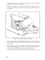
q Did you remove the plastic tab that holds the print head in place?
q Is the power source (power strip, etc.) turned ON?
q Is the ribbon properly installed? Make sure the ribbon is in front of
the print head, not riding above it.
q Have you loaded the paper correctly? (Read Chapter 2 or 3 if you
are using the optional cut sheet feeder or tractor unit.)
q Are the green POWER, ON LINE, and READY lights on the control panel ON? If not, press the ON LINE button to place the LQ
on line. If the red PAPER OUT light is ON, check that you’ve
loaded the paper correctly.
q Were you able to successfully run the self test in Step 8? If not,
check the DIP switch settings and try again.
q Is your printer properly connected to your computer? Are you
using the correct interface (serial or parallel)? If you’re using a
serial interface, have you set the DIP switches accordingly?
If you’re still having trouble printing, read the troubleshooting section in Appendix D.
1-19
Chapter 2
The Cut Sheet Feeder
The cut sheet feeder automatically loads single sheets of paper into
the LQ, allowing you to print on letterhead, bond, or individual
forms.
Installing the Cut Sheet Feeder
1. Make sure the power is OFF.
2. Set
DIP switch 1-8 on the back of the printer to the ON position
and DIP switch 1-7 to the OFF position to select the cut sheet
feeder. See Appendix A for information on resetting the DIP
switches.
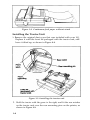
3. Remove the front cover that came installed on your LQ by tilting it
up and lifting it off the printer. Replace it with the new cover
included with the cut sheet feeder, as shown in Figure 2-1. Leave the
new cover in an upright position so you can see inside the printer.
Also remove the single-sheet guide.
Figure 2-1. Preparing the printer for installation
2-1
4. Make sure the paper release lever is pushed back as shown in Figure 2-1. If this lever is not pushed back, the cut sheet feeder will not
fit or operate properly.
5. Pull the paper bail away from the platen (the black roller) as shown
in Figure 2-1. The paper bail should remain in this position whenever the cut sheet feeder is installed.
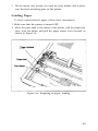
6. Now locate the rear mounting pins on the LQ as shown in Figure
2-2. The rear notches on the cut sheet feeder unit rest on these
mounting pins.
Figure 2-2. Installing the cut sheet feeder
2-2
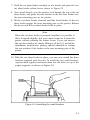
7. Hold the cut sheet feeder assembly in two hands, and press the two
cut sheet feeder release levers shown in Figure 2-1.
8. Now stand directly over the printer, look through the top of the cut
sheet feeder, and guide the rear notches on the cut sheet feeder onto
the rear mounting pins on the printer.
9. Tilt the cut sheet feeder forward until the front latches of the cut
sheet feeder engage the front mounting pins on the printer. Release
the levers and the cut sheet feeder locks in place.
Note
When the cut sheet feeder is properly installed, it is possible to
tilt it forward slightly, but you cannot remove it from the
printer without pressing the release levers. If you can remove
the cut sheet feeder by simply lifting it off the LQ, reread the
installation instructions, paying special attention to setting
the rear notches of the feeder on the rear mounting pins of the
printer.
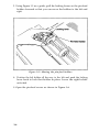
10. With the cut sheet feeder in place, you can now install the three
brackets supplied with the unit. To install the two small brackets,
squeeze them together and insert them into the holes on top of the
paper supports, as shown in Figure 2-3.
Figure 2-3. Installing the small brackets
2-3
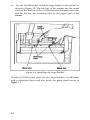
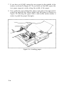
11.
For the LQ-800 model, install the large bracket in the stacker as
shown in Figure 2-4. Slip the legs of the bracket into the metal
slots on the bottom of the cut sheet feeder and make sure the
bracket fits into the retaining clips on the upper part of the
stacker.
Figure 2-4. Installing the large bracket
For the LQ-1000 model, there are two large brackets. Install them
both as described above and also install the paper stand shown in
Figure 2-5.
2-4
Figure 2-5. The LQ-1000 model
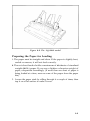
Preparing the Paper for Loading
1. The
paper must be straight and clean. If the paper is slightly bent,
curled or uneven, it will not feed correctly.
2. The
cut sheet feeder holds a maximum of 60 sheets of standard
weight (20 lb.) paper. If you use a lighter or heavier weight of
paper, compensate accordingly. (If more than one sheet of paper is
being loaded at a time, remove some of the paper from the paper
bin.)
3. Loosen the paper stack by rifling through it a couple of times, then
tap it on a flat surface to make it even.
2-5
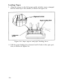
Loading Paper
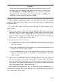
1. Align the arrow on the left paper guide with the arrow stamped
into the metal lip of the stacker, as shown in Figure 2-6.
Figure 2-6. Paper support and paper loading lever
2. Pull the paper loading lever forward until it locks in the open position, as shown in Figure 2-6.
2-6
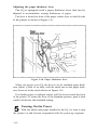
3. Set the stack of paper in the paper bin, aligning it against the left
paper guide as shown in Figure 2-7. Move the right paper guide
over to the edge of the stack of paper, but leave a little room so the
paper doesn’t bind. Make sure the paper is behind the angled metal
tabs at the bottom of the left and right paper guides.
Figure 2-7. Loading paper; adjusting the right paper guide
4. Push the paper loading lever back, and the stack of paper is pushed
forward against the two feeder rollers.
2-7
setting up your word processor for a cut sheet feeder. . .
If you‘ve never used a cut sheet feeder before, you may have to set
up your word processor accordingly.
When the cut sheet feeder positions the paper for printing, it automatically leaves a one-inch margin at the top of a page. If you’ve been
printing with continuous-feed paper, you11 need to adjust the settings
on your word processor so that the pages print the same with the cut
sheet feeder.
There are three settings you’ll probably need to change: Page
Length, Top Margin, and bottom Margin. Most word processors
have preset (or default) settings that are in effect each time you use the
program. Check the program’s documentation to find these settings,
and how to change them.
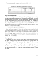
The following is an example of a typical conversion.
To maintain 55 printed lines per page:
Change Page Length from
Continuous-feed
Cut sheet
settings
feeder settings
66
to 6 1
Change Top Margin from
3
(default)
to 0
Change Bottom Margin from
8
(default)
to 6
Many word processors give you two choices in changing these settings: 1) You can change the settings in each individual file you print,
or; 2) You can change the program’s default settings so that every time
you use the program, these new settings are in effect.
If your program has additional features, such as headers and footnotes, you will have to compensate accordingly. (For example, many
programs include the header as part of the top margin. If you set the
top margin to 0, you11 lose the header.)
With a little bit of experimenting, you’ll find the best equivalent
settings to use.
2-8
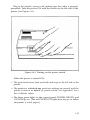
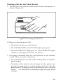
Printing with the Cut Sheet Feeder
1. Turn the power ON with the switch on the left side of the printer, as
shown in Figure 2-8.
Figure 2-8. Turning the power on
2. When you turn the power ON:
l
The print head moves to the left side.
l
The POWER, READY, and ON LINE lights glow green.
l
The red PAPER OUT light goes on. (The PAPER OUT light
remains on until paper is fed into the printer.)
3. Now print a document with your word processor as you normally
would. When you print a document:
l
l
The print head moves to the center of the platen to facilitate
paper loading.
The feeder rollers feed one sheet of paper into the printer, and
position the page with a one-inch margin at the top. (See the
previous note “Setting up your word processor for a cut sheet
feeder. . ." for information on adjusting margin and page length
settings.)
2-9
l
l
The red PAPER OUT light goes out while there’s paper in the
printer.
Printing begins.
When the LQ finishes printing a document, you have three options.
If you wish to continue printing-You can print another document as
you normally would; the cut sheet feeder ejects the last page from the
previous job, then loads and prints the new document.
If you want to fully eject the last page of a document-First take the
LQ off line by pressing the ON LINE button (the green ON LINE light
goes out). Press the FORM FEED button to eject the last page into the
paper stacker, and a new sheet is automatically loaded.
If you’re finished printing-Remove the unused paper from the bin,
take the printer off line, then use the FORM FEED button to eject the
last sheet of paper. (If you press FORM FEED without removing the
remaining paper from the bin, another sheet is loaded.) You can also
shut the power OFF, then use the manual paper feed knob to roll the
remaining sheet out of the printer.
Caution
When the power is ON, you should use only the FORM FEED
or LINE FEED button to eject paper from the cut sheet feeder.
If you use the manual paper feed knob, the power should
always be OFF to prevent damage to the paper feed motor.
Removing the Cut Sheet Feeder
To remove the cut sheet feeder:
1. Turn the power for the printer OFF.
2. Remove all the unused paper from the bin, and any printed sheets
from the stacker.
3. If a sheet of paper is still loaded in the printer, use the manual paper
feed knob to remove it.
2-10
4. Hold the cut sheet feeder on each side, press the release levers as
shown in Figure 2-9, and lift the unit off the printer.
Figure 2-9. Removing the cut sheet feeder
Remember, if you decide to print with another type of paper feed
system, such as the optional tractor feed, you’ll have to:
l
l
l
Reset DIP switch 1-8 from ON back to OFF. (Don’t forget to turn
the power OFF then ON again so the printer will record the new
setting.) Reset DIP switch 1-7 (skip-over perforation) if you’re using
continuous-feed paper.
Check any settings you might have changed in your word processor
to compensate for the cut sheet feeder.
Replace the original front cover if you’re loading individual sheets
of paper (you can leave the narrow front cover on if you’re using
the optional tractor feed unit).
2-11
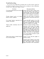
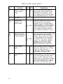
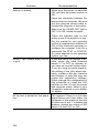
Troubleshooting
If you have any difficulties operating the cut sheet feeder, check the
troubleshooting list shown below. If you continue to have difficulty,
consult your authorized Epson dealer.
Problem
Recommendation
Cut sheet feeder does not fit flush
on the printer.
Check that the paper release lever
on the left side of the printer is
pushed back, and that the paper
bail is pulled away from the platen.
Review the installation instructions.
Printer doesn’t print; cut sheet
feeder doesn’t operate.
Make sure the cable is properly
connected to the printer and computer.
Cut sheet feeder operates but
doesn’t load paper.
Check that DIP switch 1-8 is ON
and 1-7 is OFF, and that the printer
has been switched OFF, then ON
again to recognize the settings.
Paper loads unevenly from the
paper bin.
Review the paper loading instructions-you must open the paper
loading lever first, then set the
paper on the paper shelf. If you set
the paper on the gray rollers then
open the paper loading lever, the
paper drops down too far, becomes
uneven, and does not load properly.
If too much paper is loaded, it spills
off the paper shelf.
Paper jams when it feeds through
the cut sheet feeder.
Check to see that the paper is
stacked evenly
Check to see if there is too much
space between the paper stack and
the right paper guide, causing
paper movement and unevenness.
2-12
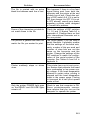
Problem
Two or more sheets of paper are
loaded instead of one.
Recommendation
Remove paper and fan it. Paper
was not sufficiently loosened
before being loaded into the paper
bin.
Make sure paper is loaded behind
the metal tabs on the bottom of the
left and right paper guides,
Too much paper was loaded into
the paper bin-remove some of the
unused sheets.
The weight of the paper is too light.
Add paper.
Printing starts too low on the page.
Your word processor may not be
set up properly. Review “Setting up
your word processor for a cut sheet
feeder . . .”
Printing is too close or too far from
the left side of the paper.
Make sure the arrow on the left
paper guide is aligned with the
arrow stamped on the lip of the
stacker.
Paper doesn’t eject evenly.
Check that there’s enough room in
the stacker. If not, remove some of
the printed sheets.
More than one sheet of paper may
have been loaded, which causes
the paper to eject unevenly Make
sure that paper was separated and
loaded properly
Maintenance
To keep your cut sheet feeder working smoothly, keep it away from
dust, grease, and any heat sources. A safe temperature range is 41° to
95°F.
Use a soft, clean cloth dampened with water to clean the outside of
the cut sheet feeder case. Stubborn stains can be removed with nonabrasive household cleaners.
2-13
Periodically, the inside of the cut sheet feeder should be cleaned to
get rid of dust and paper lint. First, turn the power OFF and remove
the cut sheet feeder from the printer. Then use a soft brush to clean the
inside areas. Make sure the gray rollers are kept free of dust so that the
paper feeds evenly.
If you have any problems, contact your authorized Epson dealer.
2-14
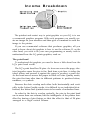
Chapter 3
The Tractor Unit
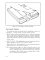
The tractor unit for the LQ is easy to install and use. Before you
begin the installation, make sure you have received the following:
l
The tractor unit
l
The smoke-colored tractor cover
l
The narrow front lid
l
The paper separator
l
The paper shelf
Setting Up the LQ for Continuous-feed Paper
Before installing the tractor unit, you should set up your LQ so that
continuous-feed paper can flow freely in and out of the printer.
Use any arrangement that allows you to put the paper underneath or
behind the printer. There are many types of printer stands you can use;
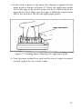
one example is shown in Figure 3-1. If you prefer, you can stack the paper
behind the printer as shown in Figure 3-2.
Figure 3-1. Continuous-feed paper with printer stand
3-1
Figure 3-2. Continuous-feed paper without stand
Installing the Tractor Unit
1. Remove
the original dust cover that was included with your LQ.
Replace it with the front lid packaged with the tractor unit, and
leave it tilted up, as shown in Figure 3-3.
Figure 3-3. Installing the tractor unit
2. Hold the tractor with the gears to the right, and fit the rear notches
on the tractor unit over the rear mounting pins on the printer, as
shown in Figure 3-3.
3-2
3. Tilt the tractor unit toward you until the front latches click in place
over the front mounting pins on the printer.
Loading Paper
To load continuous-feed paper, follow these instructions:
1. Make sure that the printer is turned OFF.
2. Move the print head to the center of the printer, pull the paper bail
away from the platen, and pull the paper release lever forward, as
shown in Figure 3-4.
Figure 3-4. Preparing for paper loading
3-3
3. Using Figure 3-5 as a guide, pull the locking levers on the pin-feed
holders forward so that you can move the holders to the left and
right.
Figure 3-5. Moving the pin-feed holders
4. Position the left holder all the way to the left and push the locking
lever back to lock that holder in place. Leave the right holder
unlocked.
5. Open the pin-feed covers as shown in Figure 3-6.
3-4
Figure 3-6. Opening the pin-feed covers
6. Now install the paper shelf by fitting it into the two notches on the
back of the printer, as shown in Figure 3-7. The paper shelf keeps
the paper from getting caught on the interface cable.
Figure 3-7. Installing the paper shelf
3-5
7. If you have an LQ-800, center the one support in the middle of the
tractor as shown in Figure 3-7. If you have an LQ-1000, space the
two paper supports evenly along the width of the paper.
8. Now guide the paper behind the platen, and push it through until it
comes up between the ribbon guide and the platen as shown in
Figure 3-8. (Moving the paper with a side-to-side motion makes it
easier to push the paper through.)
Figure 3-8. Loading paper
3-6
9. Pull the paper up until the top is above the pin-feed holders. Fit
the holes on the left side of the paper over the pins in the left
holder (as shown in Figure 3-9) and close the cover.
Figure 3-9. Fitting the paper over the pin feeds
10. Fit the right side of the paper into the right holder, moving the
holder as needed to match the width of the paper.
11. Close the right cover, making sure the paper has no dips or
wrinkles and lock the right holder in place.
12. Push the paper bail against the paper and that’s it . . . the paper is
ready.
3-7
Figure 3-10. Top-of-page position
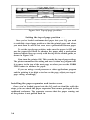
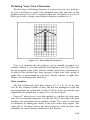
Setting the top-of-page position . . .
Once you‘ve loaded continuous-feed paper into your LQ, you need
to establish a top-of-page position so that the printed pages end where
you want them to and do not cross over a perforation between pages.
To set the top-of-page position, make sure the power is OFF and
use the paper feed knob to advance the paper until a perforation
between sheets lines up evenly with the top of the ribbon guide, as
shown in Figure 3-10.
Now turn the printer ON. This records the top-of-page setting.
The printer remembers this setting and uses it when any program tells
it to move to the top of the next page, or when you use the FORM
FEED button to advance the paper.
If you are using a word processor or other applications program
and the printing is too high or too low on the page, adjust your top-ofpage setting accordingly,
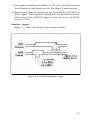
Installing the paper separator and tractor cover
Once you’ve loaded paper into the LQ and are familiar with the
steps, you can attach the paper separator that comes packaged in the
cardboard enclosure. The separator ensures that the paper coming out
of the printer is not pulled back in.
3-8
The separator has rounded pins on each end that fit into notches
located just behind the tractor unit. Slide one of the separator’s pins
into one notch, then with a gentle pressure, snap the other pin into the
other notch as shown in Figure 3-11.
Figure 3-11. Installing the paper separator
3-9
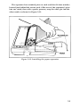
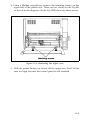
The smoked plastic tractor cover is the finishing touch. Simply
place it over the tractor unit, making sure the notches on the side of
the cover fit into the slots on the printer, as shown in Figure 3-12.
Figure 3-12. Installing the tractor cover
3-10
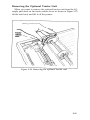
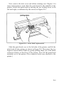
Removing the Optional Tractor Unit
When you want to remove the optional tractor unit from the LQ
simply push back on the tractor release levers as shown in Figure 3-13,
tilt the unit back, and lift it off the printer.
Figure 3-13. Removing the optional tractor unit
3-11
Chapter 4
Using the LQ with Commercial Software
Now that you have set up and tested your printer, you can do any
of these things:
l
Use the printer with commercial software (such as a word processor, spreadsheet, or database).
l
Learn about the features of the printer.
l
Write programs to use the features of the printer.
Most of you probably want to begin using your LQ with commercial software to print such items as documents, reports, letters,
spreadsheets, and graphics. This chapter tells you what you need to
know.
If you want to learn more about the features of the LQ, also read
Chapters 5 and 6. For programmers the important parts of the manual
are the command summary and the other appendixes.
Using Commercial Software
Commercial software programs usually need to know what type of
printer you are using. You normally supply this information as part of
a setup or installation process. Either the manual for your program or
an on-screen menu should explain this process for you.
The program may list a number of printers from which you can
choose. Pick LQ-800 or LQ-1000, depending on which printer you
have.
4-1
If neither one of these printers is listed, choose LQ-1500 because
that printer recognizes virtually the same codes that the LQ-800 and
LQ-1000 use. (If you have a program that does not list the LQ-1500 as
an option, you may be able to obtain an update from the manufacturer. Contact your software dealer or the manufacturer to see if an
update that includes the LQ-1500, LQ-1000, or LQ-800 is available.)
If your program does not list any LQ printers, choose a printer from
the list below. They are listed in order of preference.
FX
LX
Rx
MX
Epson printer
Draft printer
Once you have set up or installed your commercial software program for your printer, simply follow the program’s printing instructions. If you have any trouble when you print, turn to the first section
in Appendix D for help.
4-2
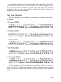
Chapter 5
LQ Features
This chapter describes many of the printing features of the LQ. You
can read this chapter if you wish, but you may not need to. Whether
or not you use the rest of this manual depends upon your expertise,
your interest, and the software you use.
The demonstration programs in this chapter enable you to see LQ
features and print styles in action. Below are a few of the many features covered:
Letter Quality
High Speed Draft
Emphasized
Double-strike
Italics
Elite
Fifteen Characters Per Inch
Underlined
D o u b l e - w i d t h
Condensed
S u p e r s c r i p t
S u b s c r i p t
Proportional
ESCape and ASCII
The details of printer-computer communication are complex, but
for most purposes all you need to know is that the computer sends a
series of codes (each consisting of one or more numbers) to the printer,
and the printer interprets them.
5-1
Some codes tell the printer to print a character, and other codes tell
it to turn on or off certain printer functions, such as emphasized or
Letter Quality. Because the codes between 0 and 127 are basically
standardized by the American Standard Code for Information Interchange (ASCII), they are referred to as ASCII numbers in this manual.
Nearly all of the codes for printer functions require more than one
number and begin with a special code, called the escape code. This
code signals that the next number is a code for a printer function and
its name is usually printed with the first three letters capitalized
(Escape) or it is abbreviated ESC or (ESC) .
In the demonstration programs in this manual, you’ll see how
ASCII and ESCape codes are used in the BASIC programming language.
l
LPRINT signals that information is to be sent to the printer.
l
The CHR$ (character string) function is used for numerical codes.
l
CHR$(27) is the ESCape code.
l
Quotation marks are used for printable characters, such as letters of
the alphabet.
Your word processing or business program may use other methods
to send those codes, such as pressing the ESC key for the ESCape
code. See your software manual for further information and use
Appendix B of this manual to find the proper codes. Appendix D also
has some suggestions on using LQ features with applications software.
Demonstration Programs
To enable you to see the LQ features in action, this manual includes
demonstrations in the BASIC programming language. Although you
will probably not do much of your printing using BASIC, the demonstrations are in BASIC because nearly all personal computer systems
include some version of this language. Therefore, almost everyone
can try the examples.
As you run the programs (or even as you read the explanations and
look at the printed examples), you learn how the LQ responds to the
messages your computer sends it by printing letters, numbers, symbols, and graphics in various print modes.
5-2
Even if you never use BASIC again, you will know the capabilities
of your printer, capabilities that can often solve your printing problems. For example, if you need a special symbol, such as a Greek letter, you will know that you can turn to the chapter on user-defined
characters and create such a character.
If you don’t want to do the exercises in BASIC, you don’t have to.
In most cases the software that you use for word processing, business,
or graphics does the calculating and communicating with the printer
for you. All you need to do is install your software as explained in
Chapter 4.
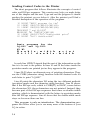
Running BASIC programs. . .
This section describes how to run the BASIC demonstration programs in this manual; it is not a tutorial in BASIC programming.
Although there are many versions of BASIC, the programs in this
manual are designed to work with the two most popular ones: Microsoft™ BASIC and IBM PC BASIC. If you have another version, you
can run these demonstration programs by making a few changes.
Appendix D has instructions for using Applesoft™ BASIC; for other
versions of BASIC, consult the appropriate manual.
When you type these programs, be sure to include all spaces and
punctuation marks, especially semicolons. Press RETURN at the end
of each line. (On your computer the RETURN key may be marked
or ENTER.) Computers that use a 40-column display may break
some lines into two parts on the screen, but that does not affect the
operation of the program. If you make a typing mistake, retype the
whole line, including the line number; the new line will replace the old
one.
When you have typed all the lines, type RUN and press RETURN
to run the program.
If you have made changes to a program and want to see all of it on
the screen, type LIST and then press RETURN to see the program on
your screen. When you are completely through with one program
and want to start another, type NEW and press RETURN.
5-3
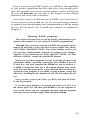
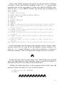
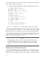
Sending Control Codes to the Printer
The short program that follows illustrates the concepts of control
codes and ESCape sequences. This exercise may help you make better
use of this chapter and the next. Type and run the program. It should
produce the printout you see below it. After the printout you’ll find a
detailed description of the operation of the program.
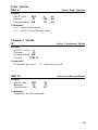
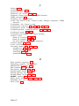
10 LPRINT "BASIC programs for the"
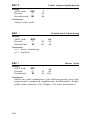
20 LPRINT CHR$(76)CHR$(81)CHR$(45);
25 LPRINT CHR$(56)CHR$(48)CHR$(48);
30 LPRINT " and LQ-1000"
40 LPRINT "W1 "CHR$(87)CHR$(49)
50 LPRINT CHR$(27)"W1";"Double-width print"
60 LPRINT "Still double-width"
Basic programs for the
LQ-800 and LQ-1000
W1 W1
p r i n t
D o u b l e - w i d t h
d o u b l e - w i d t h
S t i l l
In each line LPRINT signals that the rest of the information on the
line is to be sent to the printer. In lines 10 and 30 the letters inside the
quotation marks are printed just as they appear in the program.
Lines 20-25 show an alternate way of printing characters. They
use the CHR$ (character string) function with the decimal code for
each letter to print “LQ-800.”
Line 40 prints the characters W1 using the two different methods
(quotation marks and the character string function). Line 50 shows
that if the ESCape code, which is CHR$(27) in BASIC, comes before
the characters W1, those characters are not printed. Instead, they
become part of the ESCape sequence that turns on double-width
printing, which is demonstrated with the letters in quotation marks
after the ESCape sequence. Line 60 shows that the double-width mode
stays on for more than one line.
This program is only an introduction. The demonstration programs that follow allow you to see many more of the features of your
LQ in action.
5-4
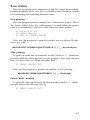
Basic Widths
The first programs print characters in the LQ’s three basic widths.
Further programs show you how to produce other character widths
by condensing and widening the basic ones.
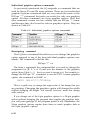
Pica printing
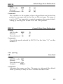
The first program prints a sample line of characters in pica. This is
the default width on the LQ, which means it is used unless the printer
receives a command to use one of the other two basic widths.
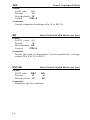
40 FOR X=65 TO 105
50 LPRINT CHR$(X);
60 NEXT X: LPRINT: LPRINT
Now run the program to print the results you see below-10 characters per inch:
ABCDEFGHIJKLMNOPQRSTUVWXYZ[\]^_'abcdefghi
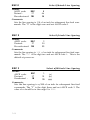
Elite printing
To print the same line of characters in elite (which is 12 characters
per inch) add the following line to your program. (Just type the new
line; you don’t have to retype the other lines.)
20 LPRINT CHR$(27)"M";
Now run the program to produce a sample of elite printing.
ABCDEFGHIJKLMNOPQRSTUVWXYZ [\]^_'abcdefghi
Fifteen mode printing
To print the same characters in the fifteen mode (which is 15 characters per inch) enter this new line 20.
20 LPRINT CHR$(27)"g";
5-5
Now run the program to produce a sample of printing in the fifteen
mode.
ABCDEFGHIJKLMNOPQRSTUVWXYZ[\]ˆ_'abcdefghi
Letter Quality and Draft
Your LQ is set at the factory to print in the Letter Quality mode
unless you turn on the draft mode with the DRAFT button on the
control panel or with a DIP switch (described in Appendix A). Therefore, the printouts in this manual are shown in Letter Quality. If you
want to see how a feature looks in the draft mode, press the DRAFT
button before you run the program. Here’s a comparison of Letter
Quality and Draft modes in pica width.
ABCDEFGHIJKLMNOPQRSTUVWXYZ[\]ˆ'abcdefghi
ABCDEFGHIJKLMNOPQRSTUVWXYZ[\]ˆ'abcdefghi
Cancelling Modes
With only a few exceptions, the LQ printing modes stay on until
they are turned off. In fact, the modes can stay on even if you change
from one type of software to another. For example, if you run a
BASIC program that turns on elite and then use a word processing
program to print a document, the LQ prints that document in the elite
mode.
There are two methods to turn off a printing mode when you no
longer need it.
l
l
With a specific cancelling code. Each mode has a cancelling code,
which you can find in the discussion of the mode and also in Appendix I.
By resetting the printer, a method explained in the next section.
Resetting the Printer
Resetting your LQ cancels all modes that are turned on. You can
reset the printer with one of two methods:
l
Sending the reset code (Escape “@”)
l
Turning the printer off and then on.
5-6
Either one of these methods returns the printer to what are called its
defaults, which are the standard settings in effect every time you turn
the printer on. Resetting the printer has two main effects. It returns the
printing to single-strike pica, thus cancelling any other pitches or
enhancements you may have turned on, and the current position of
the print head becomes the top-of-page setting. The reset code does
not cancel the draft mode if it has been selected with the panel button,
but turning off the printer does cancel the draft setting.
Some of the demonstration programs end with a reset code
(Escape “@”) so that the commands from one program will not interfere with the commands in the next one. After you run a program with
a reset code in it, remember to change the top-of-page setting before
you begin printing full pages.
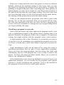
Disabling a program’s reset code
Some word processors and other applications programs send a reset
code or initialization signal to the printer before sending data to be
printed. Basically, the purpose of this code or signal is to cancel any
settings that might interfere with the program’s print control options.
In most instances, this is fine. However, if you decide you want to
set up the LQ to do something your applications program won’t do,
you have to make sure a reset code doesn’t wipe out your new settings.
Some initialization codes can be removed by using the setup or
installation procedures that are part of many applications programs.
Once you’re into the setup procedure, find the section that deals with
initialization, and see if the program has a list of codes it sends to the
printer. If it does, the setup procedure usually allows you to cancel or
remove the initialization settings.
If the initialization code cannot be disabled or removed from your
applications program,. you can usually use the program’s print options
function to control formatting and typestyles. Look in the manual for
the program to find out how to select print options.
5-7
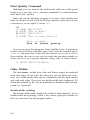
Print Quality Command
Although you can turn on the draft mode with one of the panel
buttons, you can also use a software command to switch between
draft and Letter Quality.
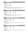
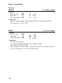
Enter and run the following program to see how Letter Quality and
draft are turned on and off by an ESCape sequence (note that you use
a lowercase x, not a capital X, in line 10).
NEW
10 LPRINT
20 LPRINT
30 LPRINT
40 LPRINT
CHR$(27)"x0";
"This is draft."
CHR$(27)"x1";
"This is Letter Quality."
This is draft.
This
is
Letter
Quality.
As you can see in this program, Letter Quality is one of the Epson
modes with an ESCape code that uses a letter with the numeral one to
turn on the mode and a letter with the numeral zero to turn it off. For
these modes, the one or zero can be inside the quotation marks, as
shown above, or as a separate character string value, as shown below:
10 LPRINT CHR$(27)"x"CHR$(0);
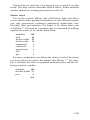
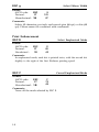
Other Widths
The three basic widths (pica, elite, and fifteen) cannot be combined
with each other. If one is on, the other two are off. There are, however, two width modes that can be combined with the basic modes
and with each other. These two are double-width and condensed. All
characters printed by the LQ are widened by double-width and narrowed by condensed.
Double-width printing
The double-width mode doubles the width of each character. To see
double-width pica printing, which is the widest typestyle available on
the LQ, enter and run the program below.
5-8
As you can see in this program, double-width is another of the
modes with an ESCape code that uses a letter with the numeral one to
turn on the mode and a letter with the numeral zero to turn it off.
Therefore, the command to turn on double-width is ESCape “W1”
and the command to turn it off is ESCape "W0".
10 LPRINT "This is standard pica."
20 LPRINT CHR$(27)"W1";"Double-width pica"
30 LPRINT "Still double-width"
40 LPRINT CHR$(27)"W0";
50 LPRINT "This is standard pica again."
This is standard pica.
p i c a
D o u b l e - w i d t h
S t i l l
d o u b l e - w i d t h
This is standard pica again.
Double-width can also be combined with any of the three basic
widths as you can see in the program below.
20 LPRINT CHR$(27)"W1";"Double-width pica"
30 LPRINT CHR$(27)"M";"Double-width elite"
40 LPRINT CHR$(27)"g";"Double-width fifteen"
p i c a
D o u b l e - w i d t h
D o u b l e - w i d t h
e l i t e
Double-width
fifteen
A later section in the chapter explains a special ESCape code, Master Select, which allows you to control nine modes with only one
ESCape sequence.
Condensed printing
Condensed is a mode that narrows pica or elite characters; the
fifteen mode cannot be condensed. Condensed is turned on by ASCII
15, as you can see in the following program. It is turned off by ASCII
18.
10 LPRINT "This is standard pica."
20 LPRINT CHR$(15)"This is condensed pica."
30 LPRINT CHR$(27) " M ";"This is condensed elite."
40 LPRINT CHR$( 27) “@"
5-9
This is standard
This is condensed pica,
This is condensed elite,
pica.
By using combinations of the various width modes, the LQ can
print nine widths, which range from 5 to 20 characters per inch (cpi) as
shown in the table below:
Table 5-1. LQ character widths
CPI
5
6
7.5
8.5
10
10
12
15
17.1
20
Typestyle
Double-width pica
Double-width elite
Double-width fifteen
Double-width condensed pica
Pica
Double-width condensed elite
Elite
Fifteen
Condensed pica
Condensed elite
Print sample
A B C D e f g h
A B C D e f g h
ABCDefgh
ABCDefgh
ABCDefgh
ABCDefgh
ABCDefgh
ABCDefgh
ABCDefgh
ABCDefgh
Print Enhancements
In addition to the widths covered, the LQ offers many print
enhancements.
Emphasized mode
In the emphasized mode the LQ prints each dot twice, with the
second dot slightly to the right of the first. In order to do this, the print
head must slow down so that it has time to fire, retract, and fire the
pins quickly enough to produce the overlapping dots. This method
produces characters that are darker than single-strike characters.
To see an example of emphasized, type and run the following program.
5-10
NEW
10 LPRINT "This is standard printing."
20 LPRINT CHR$(27)"E";
30 LPRINT "This is emphasized printing."
100 LPRINT CHR$(27)"@"
This is standard
printing.
This is emphasized printing.
Emphasized is an especially good method for emphasizing a word
or phrase in the draft mode as shown in the printout below. The code
to turn off emphasized is ESCape “F”.
In the draft mode
emphasized makes a
word
stand
out.
Double-strike
The other bold mode is double-strike. For this mode the LQ prints
each line, then moves the paper up slightly and prints the line again.
Each dot is printed twice, with the second one slightly below the
first as you can see if you run this program, which uses ESCape “G” to
turn on double-strike.
10 LPRINT "This is standard printing."
20 LPRINT CHR$(27)"G";
30 LPRINT "This is double-strike printing."
100 LPRINT CHR$(27)"@"
This
This
is standard printing.
is double-strike printing.
Since each line in this mode is printed twice, the speed of your
printing is slowed. The code to turn off double-strike is ESCape “H”.
Some users prefer the effect of emphasized, and others prefer
double-strike. You can look at the printout below and decide for
yourself.
This
is
standard
printing,
and this is emphasized printing,
and
this
is
double-strike
printing.
5-11
Underline mode
The LQ also has a mode that underlines characters and spaces. You
turn it on with ESCape “-1” and off with ESCape “-0”. Note that
the underline code is like the double-width code in that it uses a character, in this case the hyphen or minus sign, combined with numeral
one to turn it on and a character combined with the numeral zero to
turn it off. You can see it in action with the following program:
NEW
10 LPRINT "This is not underlined.”
20 LPRINT CHR$(27)"-1";
30 LPRINT "This text is underlined."
This
This
is not underlined.
text is underlined.
Proportional mode
In the standard draft and Letter Quality modes on the LQ, each
character is given the same amount of space, whether it is a narrow
letter like i or a wide letter like a capital W. In the proportional mode,
however, the space allowed for each letter is proportional to its size.
The proportional mode is always Letter Quality. You can see the
difference between standard and proportional modes if you enter and
run the following program:
10
20
30
40
LPRINT
LPRINT
LPRINT
LPRINT
CHR$(27)"p1"
"Proportional mode is on."
CHR$(27)"p0";
"Proportional mode is off."
Proportional mode is on.
Proportional mode is off.
5-12
Notice that you must use a lowercase p, not a capital P, for this
mode. The next section describes Master Select, which includes
another method for turning proportional on and off.
Master Select
The LQ has a special: ESCape code called Master Select that allows
you to choose many possible combinations of nine different modes:
pica, elite, proportional, condensed, emphasized, double-strike, double-width, italic, and underline. The format of the Master Select code
is ESCape ‘!” followed by a number that is calculated by adding
together the values of the modes listed below:
underline
128
italic
64
double-width 32
double-strike 16
emphasized
8
condensed
4
proportional
2
elite
1
pica
0
For many combinations, just add up the values of each of the modes
you want and use the total as the number after ESCape “!“. For example, to calculate the code for expanded underlined pica, add the following numbers together:
underline
128
double-width 32
pica
- 0160
5-13
To print this combination, therefore, you use ESCape “!” followed
by the number 160. In the BASIC programming language the command is CHR$(27)“!“CHR$(l60).
To try this number or any other, enter and run this short program,
which will ask you for a Master Select number and then give you a
sample of printing using that code.
10 INPUT "Master Select number";M
20 LPRINT CHR$(27)"!"CHR$(M)
30 LPRINT "This sample uses"
40 LPRINT "Master Select number";M
50 LPRINT CHR$(27)"@"
In this program, you can use any number you calculate by using the
formula above, but remember that proportional can’t be combined
with elite. If you try to combine proportional with elite, you won’t
harm your printer; proportional will simply override elite.
In the printout below you can see the result of using the number 96
with this program:
u s e s
S a m p l e
T h i s
n u m b e r
M a s t e r
S e l e c t
9 6
Master Select is a powerful code that gives you an easy way to
produce multiple combinations with a single command. To produce
double-strike emphasized underlined printing, for example, you need
only one ESCape code instead of three.
Indeed, Master Select is such a powerful feature that it may occasionally be more powerful than you want it to be. Because it controls
nine different modes, a Master Select code will cancel any of those
nine that are not selected. For example, suppose that you have a page
in elite and want part of it underlined. If you use ESCape “!" 128 to
turn on underlining, your LQ will begin printing in underlined pica
instead of underlined elite because the 128 code does not include elite.
Use 129 for underlined elite or use ESCape "-1” to turn on underlining.
If you want to use Master Select with the fifteen mode, you must
send the Master Select code before you send the command for fifteen
mode (Escape “g”). If the fifteen mode command is sent first, Master
Select will override it.
5-14
Superscript and subscript
Your LQ can also print superscripts and subscripts, which you can
use for mathematical formulas, footnotes, and other items that
require numbers or letters above or below the usual print line. ESCape
“S0” turns on superscript and ESCape "S1" turns on subscript. ESCape
“T” turns off either one. You can see them in action with the program
below :
10 LPRINT "The formula for water is H";
20 LPRINT CHR$(27)"S1";"2"CHR$(27)"T";
30 LPRINT "0."
40 LPRINT CHR$(27)"@"
The
f o r m u l a f o r w a t e r i s H 2O .
Now that you see how to use the ESCape sequences for superscript
and subscript, you can devise your own examples.
International characters
As you know, languages other than English require a few extra
characters. The LQ has provided for printing in many languages by
having 13 sets of international characters in its ROM (Read Only
Memory).
In order to print any of these characters, you first select one of the
following character sets and then use the individual characters within
that set.
0
1
2
3
4
5
6
USA
France
Germany
United Kingdom
Denmark I
Sweden
Italy
7
8
9
10
11
12
Spain
Japan
Norway
Denmark II
Spain II
Latin America
You can select any character set with an ESCape code. In BASIC it
has the following format:
LPRINT CHR$(27)"R"CHR$(n)
5-15
In this format n is the appropriate number from the list of international character sets. In other words, the BASIC command to select
the French character set is:
LPRINT CHR$(27)"R"CHR$(1)
Another method of selecting most of the international character sets
is to reset a DIP switch. If you plan to use one of the first eight international sets quite a bit, see Appendix A for instructions on using the
DIP switches.
Once you have selected a character set, whether you do it with the
ESCape code or the DIP switches, you will be able to print several new
characters. The character sets are shown in Tables 5-2, 5-3, and 5-4.
The number at the top of each column in the tables is the ASCII
code that prints the characters in that column.
Table 5-2. International characters in draft mode
USA
FRANCE
GERMANY
UK
DENMARK I
SWEDEN
ITALY
SPAIN
JAPAN
NORWAY
DENMARK II
SPAIN II
LATIN AMERICA
5-16
Table 5-3. International characters in Letter Quality mode
USA
FRANCE
GERMANY
UK
DENMARK I
SWEDEN
ITALY
SPAIN
JAPAN
NORWAY
DENMARK II
SPAIN II
LATIN AMERICA
Table 5-4. International characters in proportional mode
USA
FRANCE
GERMANY
UK
DENMARK I
SWEDEN
ITALY
SPAIN
JAPAN
NORWAY
DENMARK II
SPAIN II
LATIN AMERICA
Once you have selected an international character set with the DIP
switches or the ESCape “R” code, you can use the tables to see which
keys on your standard keyboard can produce the international characters you want. Simply type the character from the top row of one of
the figures in order to print the corresponding character in the row of
the set you have chosen.
For example, if you have reset the DIP switches for the UK character set and you press the # key, the £ symbol will be generated. Even
though you will see the # symbol on the screen, the £ symbol will be
printed on the paper. For another example, if you have selected the
Swedish character set and you press the @ key, the É symbol will be
generated.
5-17
If your keyboard does not have one of the keys that you need, you
will have to send the proper ASCII number to the printer in another
way, such as a programming language like BASIC.
Page Formatting
Although the LQ printer has many sophisticated commands to set
margins, line spacing, horizontal and vertical tabs and character spacing, this section won’t take up your time with extensive discussions of
these because most are taken care of by applications programs.
Instead, this section describes a few commands that the average user
might need. For more information, see Appendix I, where all the commands are listed and described.
Margins
The LQ allows you to set the left and right margins with simple
ESCape sequences. The left margin command is ESCape “1” followed
by the number of the column you choose for the left margin. The right
margin command is ESCape “Q” followed by the column number of
the right margin you want. (For the left margin command, be sure to
use a lowercase letter 1, not the numeral one.)
If your word processing program does not allow you to change the
margins, you can send margin commands to your LQ with BASIC or
another programming language before you print your documents.
For example, if you prefer wider margins than your word processing
program gives you, run the following BASIC program before printing. This program gives you a left margin of 10 and a right margin of
70, but you can use any numbers you prefer for the margin commands.
NEW
10 LPRINT CHR$(27)"1"CHR$(l0);
20 LPRINT CHR$(27)"Q"CHR$(70);
A program like this also allows you to choose the margins you
prefer for program listings. Just remember that once you run a program that sets margins, those margins are in effect until you change
them with new margin commands or turn off or reset the printer.
5-18
The maximum right margins are shown in Table 5-5.
Table 5-5. Maximum right margin settings
Skip-over-perforation
If you are using continuous-feed paper for printing program listings
or other material not controlled by an applications program, you may
find that the LQ prints right over the perforations between pages. The
LQ has an ESCape code to prevent this: the ESCape “N” command.
You send ESCape “N" followed by the number of lines you want the
LQ to skip at the bottom of a page. For example, in BASIC the following line will make the LQ skip six lines after each 60 lines if your
printer is set for 11-inch paper:
10 LPRINT CHR$(27)"N"CHR$(6);
Since an 11-inch page is 66 lines, this will give you one inch of blank
space at the bottom of each page. If you prefer to have half of the
blank space at the top of the page and half at the bottom, simply set
the top-of-page approximately three lines (½ of an inch) below the
perforation. (See Chapter 3 if you need to refresh your memory on
setting the top-of-page.)
Line spacing
Ordinarily you don’t have to worry about how the printer moves
the paper so that it doesn’t print lines of text on top of each other; the
LQ takes care of this without any special instructions. The line spacing
on the LQ, however, can be changed with an ESCape code.
The movement of the paper between lines is called a fine feed and
the distance the paper moves is called a line space. In ordinary printing the line spacing is 1/6 of an inch, which produces six lines of print
per inch.
5-19
The standard line spacing is the only one you need for almost all
printing of text, but in some cases you may want to increase or
decrease the space between lines. The LQ has several commands to do
this, one of which specifies the line spacing in 180ths of an inch. If you
need to make such fine adjustments in the line spacing, see Appendix I
for the proper commands. In Chapter 6 you’ll see how useful changes
in line spacing can be for dot graphics.
Half-speed Mode
When quiet is more important than speed, you can use ESCape “s”
to cut the printing speed in half. ESCape “s1” turns the half-speed
mode on, and ESCape “s0” turns it off. Note that you use a lowercase
s, not a capital S for this code.
Printing to the End of the Page
In order to protect the print head and platen, the LQ stops printing
three lines from the end of the paper. This means that when you are
printing on single sheets, you cannot use the last three lines of the
page, but that is usually reserved for the bottom margin anyway.
5-20
Chapter 6
Graphics and User-Defined Characters
The dot graphics mode allows your LQ to produce pictures,
graphs, charts, or almost any other pictorial material you can devise,
and the user-defined character feature allows you or a commercial
software program to put special characters in the LQ’s memory so that
they can be printed just as if they were ordinary letters.
Graphics
Because many commercial software programs use graphics, you
may be able to print pictures and graphs like the ones on this page and
the next by simply giving your software a few instructions.
6-1
Income Breakdown
The quickest and easiest way to print graphics on your LQ is to use
a commercial graphics program. With such programs you usually create an image on your monitor and then give a command to send the
image to the printer.
If you use commercial software that produces graphics, all you
need to know about dot graphics is how to use the software. If, on the
other hand, you wish to do your own programming or merely wish to
understand how the LQ prints graphics, read on.
The print head
To understand dot graphics you need to know a little about how the
LQ’s print head works.
The LQ’s print head has 24 pins. As it moves across the page, electrical impulses cause the pins to fire. Each time a pin fires, it strikes the
inked ribbon and presses it against the paper to produce a small dot.
As the head moves across the paper in draft or Letter Quality mode,
the pins fire time after time in different patterns to produce letters,
numbers, or symbols.
Because the dots overlap each other both horizontally and vertically in the Letter Quality mode, it is difficult to see individual dots.
Instead, the letters and symbols seem to be made of unbroken lines.
In order for the dots to overlap vertically, the pins in the print head
are in more than one column, but the intelligence of the printer handles the timing of pin firings so that the effect is that of 24 pins
arranged in a single vertical column.
6-2
Dot patterns
The LQ’s print head is able to print graphics as well as text because
graphic images are formed on the LQ about the same way that pictures in newspapers and magazines are printed. If you look closely at a
newspaper photograph, you can see that it is made up of many small
dots. The LQ also forms its images with patterns of dots, as many as
360 dot positions per inch horizontally and 180 dots vertically. The
images printed by the LQ can, therefore, be as finely detailed as the
one on the first page of this chapter.
Eight-pin graphics
So that it is compatible with the many programs written for such
printers such as the Epson FX and RX series, the LQ has an 8-pin
graphics mode with six densities. Although this mode uses only one
third of the LQ’s pins, it produces good quality graphics and allows
you to use the many programs written for 8-pin graphics.
Twenty-four-pin graphics
The graphics mode that takes full advantage of the LQ’s print head
is 24-pin graphics. It has five densities, but for simplicity this explanation will begin with only one of them, triple-density.
Triple-density prints up to 180 dots per inch horizontally. As the
print head moves across the paper, every 1/180th of an inch it must
receive instructions about which of its 24 pins to fire. At each position
it can fire any number of pins from none to 24. This means that the
printer must receive 24 bits of information for each column it prints.
Since the LQ uses 8-bit bytes of information in its communication
with a computer, it needs three bytes of information for each position.
Pin labels
To tell the printer which pins to fire in each column, you first divide
each of the vertical columns into three sections of eight pins each and
consider each section separately. Since there are 256 possible combinations of the eight pins in each section, you need a numbering system
that allows you to use a single number to specify which of the 256
possible patterns you want. This numbering system is shown in Figure
6-1.
6-3
128
64
32
16
8
4
2
1
Figure 6-1. Pin numbering system
To fire any one pin, you send its number. To fire more than one pin
at the same time, add up the numbers of the pins and send the sum to
the printer. With these labels for the pins, you fire the top pin by sending 128. To fire the bottom pin, you send 1. If you want to fire only the
top and bottom pins, you simply add 128 and 1, then send 129.
By adding the appropriate label numbers together, you can fire any
combination of pins. Figure 6-2 shows three examples of how to calculate the number that will fire a particular pattern of pins.
Figure 6-2. Calculations for pin patterns
With this numbering system, any combination of the eight pins
adds up to a decimal number between 0 and 255, and no numbers are
duplicated.
Since there are 24 pins in each column, you must make a calculation
for each of the three sections in each column. As you can see, this
method of planning and printing dot graphics requires considerable
calculation. Because triple-density uses 180 columns per inch, printing
6-4
a single line of triple-density graphics only one inch long requires 540
numbers. Fortunately, commercial software can do the calculations
for you.
Before you can put these numbers in a graphics program, however,
you need to know the format of the graphics command.
Graphics Command
The graphics mode command is quite different from the other commands covered so far in this manual. For most of the other LQ modes,
such as emphasized and double-width, one ESCape code turns the
mode on and another turns it off. For graphics, the command is more
complicated because the code that turns on a graphics mode also
specifies how many columns it will use. After the LQ receives this
code, it interprets the next numbers as pin patterns and prints them on
the paper.
The LQ has one command that allows you to use any of the 11
graphics options. The format of the command is:
ESCape “*” m n1 n2 data
In this command, m selects the graphics option and n1 and n2 specify the number of columns to reserve for graphics. The available
graphics options are listed in Table 6-1.
Table 6-1. Graphics Options
*Adjacent dots cannot be printed in this mode
6-5
Column reservation numbers
The graphics command requires more than one number to specify
how many columns to reserve because one line can use thousands of
columns, but the LQ does not use numbers larger than 255 (decimal).
Therefore, the graphics mode command uses two numbers for reserving columns.
To figure the number of columns reserved, multiply the second
number by 256 and add it to the first number. Since the command is
set up for two numbers, you must supply two even if you need only
one. When you need fewer than 256 columns, just make n1 the number of columns you are reserving and make n2 a zero.
For example, if you wish to send 1632 columns of graphics data, n1
should be 96 and n2 should be 6 because 1632 = 96 + (6 x 256).
The LQ will interpret the number of bytes determined by n1 and n2
as graphics data, no matter what codes they are. This means that you
must be sure to supply enough bytes of graphics data or the LQ will
stop and wait for more data and will seem to be locked. If, on the
other hand, you supply too much graphics data, the excess will be
interpreted and printed as regular text.
First graphics program
This first program is just a simple example to show you how the
graphics command, column reservation numbers, and data can be
used in a BASIC program. Type in and run the following program; be
especially careful to include both semicolons. The program produces
the printout you see below it.
20 LPRINT CHR$(27)"*"CHR$(32)CHR$(40)CHR$(0);
30 FOR X=1 TO 120
40 LPRINT CHR$(170);
50 NEXT X
6-6
Line 20 selects single-density 24-pin graphics (mode 32 from Table
6-1) and also reserves 40 columns for graphics. Since 24-pin graphics
requires three bytes of data for each column, line 30 begins a loop to
supply 120 bytes of data. Line 40 contains the number 170 that produces the first pin pattern shown in Figure 6-2, and line 50 finishes the
loop.
Using hand-calculated data to print graphics
With what you know now, you can use the simplest application of
graphics-using hand-calculated data to print graphic images. While
this method is the most tedious, it helps you understand dot graphics.
Also, it is useful for small graphic elements that are used many times.
Figure 6-3 shows how you can use a grid to plan where you want
dots to be printed. This grid is for a single line of graphics 42 columns
long. Since each line of 24-pin graphics is approximately 1/8th of an
inch high and since triple-density graphics prints 180 dots per inch
horizontally, a design planned on this figure will be about 1/8th of an
inch high and less than 1/4th of an inch wide.
Figure 6-3. Pattern on grid
The actual pattern that the LQ prints on the paper is, of course,
made up of dots that overlap each other both vertically and horizontally. The reason the planning grid uses an X for each dot is that using
an accurate representation of the dots makes calculating the data
numbers difficult because they cover up each other. Therefore,
remember that each X represents the center of a dot, and the dots
actually overlap each other.
6-7
Write the assigned values of the pins next to your design and then
total the values for each column of dots. These totals are the values
that will be sent to the printer as graphics data to print the design.
Figure 6-4 shows the same grid divided into three sections to make
the data calculation easier. At the the bottom of each section of each
column is the total of the pin numbers for that section. This gives you
a total of 126 data numbers necessary to print this small figure.
Figure 6-4. Data layout for 24-pin graphics
6-8
Here is the BASIC program that prints the design shown in Figures
6-3 and 6-4. Notice that the data numbers in lines 80-140 are the same
numbers that you see in Figure 6-4. Also note that the WIDTH statement in line 10 is for IBM PC BASIC; the format may be different for
your system.
10 WIDTH "LPT1:",255
20 LPRINT CHR$(27)"*"CHR$(39)CHR$(42)CHR$(0);
30 FOR X=1 TO 126
40 READ N
50 LPRINT CHR$(N);
60 NEXT X
70 LPRINT
80 DATA 0,0,63,0,0,127,0,0,255,0,3,255,0,15,255,0,31,255
90 DATA 0,127,255,0,255,255,1,255,255,3,255,7,255,
255,15,255,255
100 DATA 31,255,254,31,255,252,31,255,248,31,255,240,31,
255,224,31,255,192
110 DATA 31,255,0,31,252,0,31,240,0,31,224,0,31,128,0,
31,240,0
120 DATA 31,255,192,28,255,224,28,127,240,28,15,248,30,
0,252,31,0,126
130 DATA 15,128,15,7,192,7,3,240,7,1,254,7,0,255,7,0,
127,135
140 DATA 0,31,199,0,7,231,0,1,247,0,0,255,0,0,127,0,0,63
In this program, line 20 assigns the graphics option (24-pin tripledensity) with code 39. Code 42 sets the number of pin columns at 42.
Lines 80-140 contain 126 bytes of data (42 pin columns x 3 bytes for
each pin column). Lines 30-60 print the design that you see below.
Notice that the dots overlap quite a bit. This design was printed
using the triple-density 24-pin graphics option because the density is
the same (180 dots to the inch) in both directions.
Adding the following lines to the program above will cause the
pattern to print 10 times in a row as shown below.
15 FOR C=l TO 10: RESTORE
65 NEXT C
6-9
Individual graphics options commands
As previously mentioned, the LQ responds to commands that are
used by Epson FX and RX series printers. There are four individual
graphics options commands that are very much the same as the
ESCape “*” command, but each one works for only one graphics
option. All these commands are 8-pin graphics options. Note that
these commands contain one less variable than the ESCape "*" command because they don’t need to select a graphics option. They are
shown in Table 6-2.
Table 6-2. Individual graphics options commands
Reassigning command
The LQ has a command that allows you to change the graphics
option assigned to any of the four individual graphics options commands. The command looks like this:
ESCape “?” s m
The letter s represents the command that you wish to change the
assignment for (K, L, Y, or Z) and m is the number of the graphics
option (from Table 6-1) that you want to assign to it. For example, to
change the ESCape “K” command to use the CRT I screen graphics
option, the command in BASIC is:
LPRINT CHR$(27)"?";"K"CHR$(4)
This is a quick way to change the aspect ratio of the design that you
are printing. Changing the graphics option will change the width
without changing the height. You should, however, make this change
with caution.
If you change one of the 8-pin graphics options to a 24-pin graphics
option without changing the program that supplies the graphics data,
you will print garbage (if the program prints at all). Remember, the
24-pin graphics options require three times as much graphics data as
the 8-pin graphics options.
6-10
User-Defined Characters
With the LQ, it is possible to define and print characters of your
own design. You can design an entirely new alphabet or typeface,
create characters for special applications such as mathematical or
scientific symbols, or create graphic patterns with user-defined characters to serve as building blocks for larger designs.
Below you can see samples of typefaces created with the userdefined character function.
You can make the task of defining characters easier by using a commercial software program that assists you in creating characters or
simply supplies you with sets of characters already created. Also,
some popular commercial software programs take advantage of the
LQ’s user-defined character function to enhance printouts. (These
characters are called download characters in some programs.)
The standard characters are stored in the LQ’s Read Only Memory
(ROM), and the user-defined characters are stored in the LQ’s Random Access Memory (RAM). In order to free the LQ’s RAM for use in
storing user-defined characters be sure that DIP switch 1-4 is OFF. The
switch is set to OFF at the factory, but if you have turned it ON to use
the 7K buffer, turn it OFF before you begin this section. (See Appendix
A for instructions on changing DIP switches.)
Design grids
User-defined characters are like dot graphics because you send the
printer precise instructions on where you want each dot printed. In
fact, planning a user-defined character is like planning a small dot
graphics pattern.
To design a character you use a grid that is 24 dots high-one dot
for each wire on the LQ print head. The width of the character matrix
is dependent upon the character set in use. For draft characters, the
grid is nine dots wide. For Letter Quality it is 29 dots wide, and for
6-11
proportional characters it is 37 dots wide, with the dots for both Letter
Quality and proportional spaced more closely together than those for
draft .
Figure 6-5 shows the two design grids. The line at the side labelled
cap indicates the top of a standard capital letter, and the line labelled
base indicates the baseline for all letters except those with descenders
(the bottom parts of such letters as j and y). The bottom row is usually
left blank because it is used for underlining.
Draft pica
Letter Quality/Proportional
Figure 6-5. Design grids
The grid on the right side of Figure 6-5 can be used for either Letter
Quality or proportional characters. For Letter Quality you do not use
all the columns. See Table 6-3 for further information.
There is one restriction in designing characters. Dots in the same
row may not print in adjacent columns. That is, there must be an
empty dot position to the left and to the right of each dot that prints.
This is true in draft, Letter Quality, and proportional.
6-12
Defining Your Own Characters
The first step in defining characters is to place the dots on a grid just
as you want them to print. The examples here, like the ones in the
graphics section, use an X to represent each dot. In Figure 6-6 you see a
draft grid with a simple user-defined character planned on it.
Figure 6-6. User-defined character
Now you translate the dot pattern you’ve created on paper to a
numeric format so you can send the information to the LQ. Every dot
has an assigned value. Each vertical column (which has a maximum of
24 dots) is first divided into three groups of eight dots. Each group of
eight dots is represented by one byte, which consists of eight bits.
Hence, one bit represents each dot.
Data numbers
The bits within each byte have values of 1, 2, 4, 8, 16, 32, 64, and
128. In the vertical column of dots, the bits are arranged so that the
most significant bit (which has a value of 128) is at the top and the least
significant bit (which has a value of 1) is at the bottom.
Figure 6-7 shows how to use this method to calculate the data numbers for the example character. On the left side of the figure the data
numbers are calculated for the middle column. The value of each byte
is calculated by adding the values of the rows where dots appear. The
right side of the figure shows the whole character with the three data
numbers for each column indicated at the bottom.
6-13
This manual uses decimal numbers because the example programs
in this manual are written in BASIC and everyone is familiar with
decimals. The data you send to the LQ, however, can be in any form
(binary, decimal, hexadecimal) that you can use with your programming language.
Figure 6-7. Calculating the data
You’ve seen how to design a character by placing dots on a grid and
translated the dots to decimal equivalents. The last step in defining a
character is to send this information to the printer.
Sending information to the LQ
The printer loads characters in the print style (Letter Quality, draft,
or proportional) that the printer is currently using. It also records
whether italic or script (either superscript or subscript) is turned on.
This means that if you want to print a character in the italic mode, for
example, you must have the italic mode turned on when you define
the character.
6-14
The LQ command to define characters is one of the most complex in
its repertoire. The format of the command is this:
ESCape “&” 0 nl n2 d0 dl d2 data
The ESCape “&" is simple enough. The 0 (which is ASCII code 0,
not the numeral zero in quotation marks) allows for future enhancements. At this time it is always ASCII 0.
With the LQ, you can define many characters with a single command. The values n1 and n2 are the ASCII codes of the first and last
characters you are defining. If you are defining only one character, n1
and n2 are the same. You can use any codes between 32 and 127 decimal for nl and n2, but it is best not to define decimal 32, which is the
code for a space. Also, you can use letters in quotation marks instead
of ASCII numbers for n1 and n2.
An example will show how to specify n1 and n2. If, for instance,
you wanted to redefine the characters A through Z, n1 would be “A”
(or ASCII code 65) and n2 would be “Z” (or ASCII code 90). So the
command ESCape "&" 0 “AZ” (followed by the appropriate data)
would replace the entire alphabet of capital letters.
Following the specification of the range of characters to be defined
in this command are three data bytes (d0-d2) that specify the width of
the character and the space around it. The left space (in dot columns)
is specified by d0, and the right space is specified by d2. The second
byte (d1) specifies the number of columns of dots that are printed to
make up the character. By varying the width of the character itself and
the spaces around it, you can create proportional-width characters
that print at draft speed. Table 6-3 shows the maximum values for
these bytes.
Table 6-3. Character width limits
The last part of the character definition is the actual data that
defines the dot patterns for each character. Since it takes three bytes
6-15
to specify the dots in one vertical column of dots, the LQ expects
dl x 3 bytes of data to follow d2.
An example character definition program should make this clear:
10 LPRINT CHR$(27)"x0"
20 LPRINT CHR$(27)"&"CHR$(0);
30 LPRINT "@@";
40 LPRINT CHR$(1)CHR$(9)CHR$(l);
50 FOR I=1 TO 27
60 READ A: LPRINT CHR$(A);
70 NEXT I
80 LPRINT "@@@@@"
90 LPRINT CHR$(27)"%"CHR$(l);
100 LPRINT "@@@@@"
110 LPRINT CHR$(27)"%"CHR$(0);
120 LPRINT "@@@@@"
130 END
140 DATA 1,0,0,2,0,0,4,0,0
150 DATA 8,0,0,23,255,240,8,0,0
160 DATA 4,0,0,2,0,0,1,0,0
In line 10, the ESCape “x” command selects draft style printing.
The actual character definition starts in line 20. The two at signs
(@) in line 30 represent nl and n2, the range of characters being
defined (in this case, a range of one). Line 40 contains d0, dl, and d2.
The information about the actual character design (which is contained in the data statements at the end of the program) is sent to the
printer in the loop between lines 50 and 70.
Note
When defining Letter Quality or proportional characters, put
a WIDTH statement in your program to prevent carriage
return and line feed codes from interfering with your definitions .
Printing User-Defined Characters
If you entered the example program above, you defined an arrow
and placed it in the RAM location for ASCII code 64 (replacing the at
sign). You can now print out a three line sample of your work. The
6-16
first and third lines (printed by lines 80 and 120 of the program) print
the normal at sign; the second line (line 100) prints the arrow that you
defined. Run the program to see the printout below:
@@@@@
@@@@@
As you can see, both sets of characters (the original ROM characters that the printer normally uses and the user-defined character set)
remain in the printer available for your use. The command to switch
between the two sets is used in lines 90 and 110. It is:
ESCape “%” n
If n is equal to 0, the normal ROM character set is selected (this is
the default). If n is equal to 1, the user-defined character set is selected.
If you select the user-defined character set before you have defined
any characters, the command is ignored; the ROM characters will still
be in use.
You may switch between character sets at any time-even in the
middle of a line. To try it, place semicolons at the end of lines 80 and
100 in the program above.
Copying ROM to RAM
After running the program above, if you select the user-defined
character set and try to print other characters, the only one that will
print is the arrow. Since no other characters are in the user-defined
RAM area, nothing else prints. Other characters sent to the printer
don’t even print as spaces; it’s as if they were not sent at all.
In many cases, you will want to redefine only a few of the characters to suit your needs; the rest of the alphabet will work fine as it is.
As you have seen, it is possible to switch back and forth at will
between the normal character set and the user-defined character set. It
is, however, rather inconvenient.
Therefore, the LQ has a command which allows you to copy all of
the standard characters from ROM to the user-defined character set.
The command format is:
ESCape “:“ 0 0 0
6-17
Note
This command will cancel any user-defined characters you
have created. You must send this command to the printer
before you define characters.
If you use this command at the beginning of a program, then define
your special characters and select the user-defined character set, you
can print with the user-defined set as your normal character set. You’ll
never need to switch back and forth between sets.
Letter Quality characters
If you select Letter Quality printing with the ESCape “xl” command, you can design user-defined characters using up to 29 columns
of the Letter Quality/Proportional grid. The dot columns are spaced
closer together horizontally than draft style dot columns (the horizontal dot spacing is 1/360th of an inch as opposed to 1/120th of an inch
for draft characters).
Proportional mode characters
Selecting the proportional character mode will yield user-defined
characters of the highest resolution. Characters can be designed using
all 37 columns of the Letter Quality/Proportional grid.
Remember that in Letter Quality and proportional, as in draft, you
cannot place dots in adjacent columns. There must be an empty dot
position to the left and right of each dot that prints.
Superscripts and subscripts
You can also create superscript and subscript user-defined characters. Just as Letter Quality characters are defined when the Letter
Quality mode is selected, super/subscript characters are created when
either superscript or subscript is selected.
These super/subscript characters can be used either as superscripts
or as subscripts. The characters are exactly the same; it is only their
placement that differs. The difference between super/subscript
6-18
characters and regular characters is that they are smaller. They are a
maximum of 16 dots high and their width in dot columns is shown in
Table 6-4.
Table 6-4. Super/subscript widths
d1
(maximum)
7
23
23
Draft
Letter Quality
Proportional
d0 + dl + d2
(maximum)
12
36
42
Since super/subscript characters are smaller, they don’t require as
much information when you define them. When you define super/
subscript characters, you need only two bytes of data for each vertical
row of dots. Design grids for these characters are shown in Figure 6-8.
Draft pica
Letter Quality
and Proportional
Figure 6-8. Grids for super/subscript characters
Mixing print styles
Each of the three user-defined character modes (draft, Letter Quality, and proportional) can be used in combination with most of the
LQ’s various print styles. For instance, emphasized works with userdefined characters. The characters you design are enhanced to give
this printing effect.
6-19
Mixing the three types of user-defined characters is not permitted.
If, for example, you select draft and define some characters, then
select proportional and define some more, the first character definitions will be destroyed. Only one type of character definition may be
stored in RAM at any time.
If you define characters in one mode, then switch to another mode
and select the user-defined character set, the command will be ignored
and nothing will print. The user-defined character definitions, however, remain unaffected. If you switch back to the mode in which they
were defined, you can then select and print them.
Keep in mind that user-defined characters are stored in RAM,
which is not permanent. Whenever the printer power is turned off, or
the printer is initialized with the ESCape “@" command, all of the
user-defined characters are lost. Also, your computer sometimes
sends an initialization (INIT) signal, which wipes out all user-defined
characters. (Some computers do this each time BASIC is loaded.)
6-20
Appendix A
The DIP Switches
Your LQ is equipped with sixteen DIP (Dual In-line Package)
switches that allow you to change many of the printer’s settings to suit
your printing needs.
The DIP switches are located on two panels on the back of the
printer as shown in Figure A-1, and can be easily changed with a thin,
pointed object.
Figure? A-1. The DIP switch panels
A-1
If you are using the serial interface on the LQ, then you need to
check switches 2-3, 2-4, 2-5, and 2-6 to make sure the settings match
those on your computer.
Remember
Each time you change a DIP switch setting, you should turn
the power OFF reset the switch or switches, then turn the
power ON again. The LQ only recognizes a new setting at the
time the power is turned ON.
The following tables describe the switches and their functions. The
shaded gray boxes indicate the factory settings.
A-2
Table A-1. DIP switch panel 1
Switch
No.
1-1
1-2
1-3
Function
ON OFF
International
character set
selection
See Table
A-3
Explanation
These three switches select the
International character sets shown in
Table A-3 When you receive your
LQ, the switches are set for the USA
character set. To see the other
character sets, turn to the end of
Appendix B.
1-4
select large or
small buffer
capacity
7K
1K
1-5
Select Letter
Quality or draft
print style
draft
LQ You can select the draft mode or the
-6
Condensed
characters
ON
OFF Condensed characters are useful
when you’re printing spreadsheets
and other documents where you
need to print as much on a page as
possible. If you set this switch to ON
everything you print will be in
condensed mode (unless a software
command overrides it).
1-7
One-inch skip-over
perforation
ON
OFF If your commercial software does
not automatically skip over the
perforation between sheets of
continuous-feed paper, set this
switch to ON and set the top-of-page
3 lines below the perforation. The LQ
then automatically leaves a top and
bottom margin of ½ inch on each
page, and skips over the
perforations. Set this switch OFF
vyhen using cut sheet feeder.
1-8
Cut sheet feeder
ON
OFF Set this switch to ON only when
using the optional cut sheet feeder.
The buffer stores data from your
computer. When you receive your
LQ, the buffer is set for 1 kilobyte
(OFF), which allows the printer to
use user-deftned (downloaded)
characters. If you want to free your
computer while the LQ prints,
change the setting to 7 kilobytes
(ON).
Letter Quality mode to be in effect
when you turn the power on. You car
still select either mode using the
control panel buttons.
= Factory setting When delivered
A-3
Table A-2. DIP switch panel 2
Switch
No.
Function
2-1
Select 11 -inch or
12-inch paper
length
2-2
Not used
2-3
2-4
Select serial
interface and
parity setting
12”
11”
See Table
A-4
2-5
2-6
Explanation
ON OFF
Select the baud
rate if you’re using
a serial interface
See Table
A-5
The LQ must know the length of
paper being used in order to skip
perforations and establish top-ofpage setting. Most continuous-feed
and single-sheet paper is 11 inch.
When you receive your LQ, the DIP
switches are set for a parallel
interface. If your computer uses a
parallel interface, you don’t have to
change anything. If your computer
uses a serial interface, find what
parity setting it requires, and set
these switches according to Table
A-4.
If you’re using a serial interface, use
these switches to set the baud
rate-the rate at which the printer
receives data from the computer
You should check your computer
manual (or commercial software
program) for baud rate setting
requirements, and set these
switches according to Table A-5.
2-7
Printer select
signal
ON
OFF When this switch is ON, the printer
cannot be deactivated by software
codes. For most uses and
commercial software programs, you
should leave this switch ON.
2-8
Automatic line
feed
ON
OFF When this switch is ON, the LQ adds
a line feed to each carriage return;
when it is OFF: it does not. If your
printing has an extra space between
lines, turn the switch OFF. If all the
lines of your printing are on top of
each other, turn the switch ON.
= Factory setting when delivered
A-4
Table A-3. International DIP switch settings*
1-2
1-3
France
1-1
O N
ON
ON
ON
ON
OFF
Germany
ON
OFF
ON
U K
Denmark
O N
OFF
OFF
OFF
O N
O N
Sweden
OFF
O N
OFF
Country
USA
Italy
OFF
OFF
O N
Spain
OFF
OFF
OFF
*There are five additional international character sets available through software
commands-Japan, Norway, Denmark II, Spain II, and Latin America. See
Chapter 5 for additional information.
Table A-4. Interface selection
Function
2-3
8-bit parallel interface
OFF
O N
OFF
Serial interface, Even parity
Serial interface, Odd parity
Serial interface, Non parity
ON
2-4
OFF
OFF
ON
ON
Table A-5. Baud rate selection
Baud rate
2-5
300
1200
OFF
OFF
O N
OFF
OFF
ON
O N
ON
4800
9600
2-6
= Factory setting when delivered
A-5
Appendix B
The LQ Character Set
and ASCII Table
This table shows the three LQ character sets: Draft, Letter Quality,
and Proportional. The table also shows the Decimal and Hexadecimal
values of each character.
The codes from O-32 and 127-160 are control codes and therefore
not represented by characters. For these codes, the abbreviations of
the functions are listed (i.e. BS for Backspace, LF for Line Feed, etc.).
For those programs that make use of control keys, these values are
also listed. Appendix I contains complete descriptions of each control
code.
Dee Hex
0
00
1
01
2
3
4
5
6
7
8
9
10
11
12
13
14
15
16
02
03
04
05
06
07
08
09
0A
0B
0c
0D
0E
0F
10
Abbrev Control key
NUL
SOH
STX
ETX
EOT
ENQ
ACK
BEL
BS
HT
LF
VT
FF
CR
so
SI
DLE
Cntl-@
Cntl-A
Cntl-B
Cntl-C
Cntl-D
Cntl-E
Cntl-F
Cntl-G
Cntl-H
Cntl-I
Cntl-J
Cntl-K
Cntl-L
Cntl-M
Cntl-N
Cntl-0
Cntl-P
Dec Hex
17
18
19
20
21
22
23
24
25
26
27
28
29
30
31
32
11
12
13
14
15
16
17
18
19
1A
1B
1C
1D
1E
1F
20
Abbrev Control key
DC1
DC2
DC3
DC4
NAK
SYN
ETB
CAN
EM
SUB
ESC
FS
GS
RS
us
SP
Cntl-Q
Cntl-R
Cntl-S
Cntl-T
Cntl-U
Cntl-V
Cntl-W
Cntl-X
Cntl-Y
Cntl-Z
Cntl-[
B-1
Dee
Hex Draft LQ Prop.
Dec
Hex Draft LQ Prop.
32
33
34
35
36
37
38
39
40
41
42
43
44
45
46
47
48
49
50
51
52
53
54
55
56
57
58
59
60
61
62
63
64
65
66
67
68
69
70
71
72
73
74
20
21
22
23
24
25
26
27
28
29
2A
2B
2c
75
76
77
78
79
80
81
82
83
84
85
86
87
88
89
90
91
92
93
94
95
96
97
98
99
100
101
102
103
104
105
106
107
108
109
110
4B
4c
4D
4E
4F
50
51
52
53
54
55
56
57
58
59
5A
5B
5c
5D
5E
5F
60
61
62
63
64
65
66
67
68
69
6A
6B
6C
6D
6E
6F
70
71
72
73
74
B-2
!
)
!
"I
#
$
%
&
'
(
)
*
*
aa
#
$
%
&
'
(
+
I
"
#
$
%
&
,
(
)
*
+
+
2D
'
'
'
2E
2F
30
31
32
33
34
35
36
37
38
39
3A
3B
3c
3D
3E
3F
40
41
42
43
44
45
46
47
48
49
4A
.
.
.
/
0
1
2
3
4
5
6
7
8
9
:
<
=
>
?
@
/
0
1
2
3
4
5
6
7
8
9
:
.
<
=
>
?
@
A
A
B
B
c
D
c
D
E
F
E
F
;
G
G
H
H
I
J
I
J
/
0
1
2
3
4
5
6
7
8
9
..
.
,
<
=
>
?
@
A
B
C
D
E
F
G
H
I
J
111
112
113
114
115
116
K
L
M
N
0
P
Q
R
s
T
u
v
w
x
Y
z
K
L
M
N
0
P
K
L
M
N
0
P
Q
Q
R
S
T
u
v
w
x
Y
z
R
S
T
U
v
W
X
Y
Z
[
[
\
]
[
^
^
^
_
_
_
\
]
\
]
'
'
a
a
a
b
b
c
d
e
f
g
h
b
c
d
e
c
d
e
f
g
h
i
'
f
g
h
i
i
j
j
k
1 1
k
l
j
k
m
n
m
n
m
n
0
0
0
P
P
q
P
Q
r
s
t
q
r
s
t
r
s
t
Dec
117
118
119
120
121
Hex Draft
u
75
76
77
78
79
Dec
Hex
127
128
129
130
131
132
133
134
135
136
137
138
139
140
141
142
143
7F
80
81
82
83
84
85
86
87
88
89
8A
8B
8C
8D
8E
8F
Dec
161
162
163
164
165
166
167
168
169
170
171
172
173
174
175
176
AB
AC
AD
AE
AF
BO
Hex Draft
122
123
124
125
126
7A
7B
7c
7D
7E
U
v
V
V
W
W
x
X
X
Y
Y
Y
Abbrev.
DEL
NUL
SOH
STX
ETX
EOT
ENQ
ACK
BEL
BS
HT
LF
VT
FF
CR
so
SI
Al !
A2 ”
A3
#
A4
$
%
A5
A6 &
A7
'
A8
(
LQ Prop.
!
”
#
$
%
&
'
(
!
",
#
$
%
&
'
+
+
'
'
(
)
*
+
,
.
.
9
AA
Dec
U
w
Hex Draft
A
LQ Prop.
)
*
.
-
/
0
)
*
-
/
0
-
/
0
Dec
Hex
144
145
146
147
148
149
150
151
152
153
154
155
156
157
158
159
160
90
91
92
93
94
95
96
97
98
99
9A
9B
9c
9D
9E
9F
A0
Dec
177
178
179
180
181
182
183
184
185
186
187
188
189
190
191
192
z
-{
LQ Prop.
Z
z
{
{
|
}
~
}
~
|
}
~
Abbrev.
DLE
DC1
DC2
DC3
DC4
NAK
SYN
ETB
CAN
EM
SUB
ESC
FS
GS
RS
us
SP
Hex Draft LQ
Bl
B2
B3
B4
B5
B6
B7
B8
B9
BA
BB
BC
BD
BE
BF
co
1
2
7
1
2
3
4
5
6
7
8
8
3
4
5
6
9
:
;
<
=
>
?
@
9
:
;
<
=
>
?
@
Prop.
1
2
3
4
5
6
7
8
9
.
.
,
<
=
>
?
@
B-3
Dec
Hex Draft LQ Prop.
193
194
195
196
197
198
199
200
201
202
203
204
205
206
207
208
209
210
211
212
213
214
215
216
217
218
219
220
221
222
223
Cl
A
C2
B
C3
C
C4
D
C5
E
C6
F
C7
G
C8
H
C9
I
CA
J
K
CB
CC
L
CD
M
CE
N
CF
O
D0
P
Dl
Q
D2
R
s
D3
D4
T
D5
U
D6
v
D7
W
D8
x
D9
Y
DA
Z
DB
[
DC
\
DD
]
DE
^
D F _
B-4
A
B
C
D
E
F
G
H
I
J
A
B
C
D
E
F
G
H
I
J
K
K
L
L
M
M
N
N
O
O
P P
Q
Q
R
R
s
s
T T
U
U
v
v
W
W
x
x
Y
Y
Z Z
[
\
[
]
^
_
\
^
_
]
Dec
Hex Draft LQ Prop.
224
225
226
227
228
229
230
231
232
233
234
235
236
237
238
239
240
241
242
243
244
245
246
247
248
249
250
251
252
253
254
E0
E1
E2
E3
E4
E5
E6
E7
E8
E9
EA
EB
EC
ED
EE
EF
FO
Fl
F2
F3
F4
F5
F6
F7
F8
F9
FA
FB
FC
FD
FE
'
a
b
c
d
e
f
g
h
i
j
k
l
m
n
O
,
'
a
b
c
d
e
f
g
h
i
j
k
l
m
a
b
C
d
e
f
g
h
i
j
k
1
m
n
n
0
O
p
q
r
s
p
q
r
P
q
r
S
S
t
t
t
u
u
V
V
w
x
y
z
{
|
}
~
U
V
w
x
Y
{
|
}
~
W
X
z
Y
z
{
|
}
~
Appendix C
Installing the Option Cartridge
The option cartridge for the LQ lets you change typestyles, extend
the capabilities the printer, or use programs designed for other popular printers. Full instructions on their use come with each module.
The cartridge is made up of two modules-the identity module and
the font module. These two modules are plugged together to form an
option cartridge, as shown in Figure C-1. The cartridge can then be
plugged into the LQ’s option cartridge compartment as shown in Figure C-2.
Figure C-1. Plugging the identity and font modules together
C-1
Figure C-2. Installing an option cartridge
The Identity Module
The identity modules can enhance the LQ’s capabilities or give it the
“personality” of another printer. Identity modules include:
l
l
l
ESC/P Expansion (Epson Standard Code for Printers Expansion)
#7696—This module maintains full Epson command capability,
while adding the Epson Standard Graphics Set, access to additional
typestyles with font modules, and greater flexibility for setting
default values.
IBM PC #7695*—This module lets you use commands and programs designed for the IBM 5152 Graphics Printer.
Diablo 630 #7694*—This module lets you use commands and programs designed for the Diablo 630 printer.
*Note: Many programs support the Epson LQ printer series. If your
software programs are set up for the IBM 5152 or the Diablo
630, you may be able to reset them for the LQ, instead of
purchasing a IBM or Diablo option cartridge. Refer to Chapter 4 for further setup information.
C-2
An identity module can be used with a font module or by itself.
Bach identity module comes with a blank font module plugged into it.
If you use an identity module by itself, leave the blank font module
plugged in. If you use a font module, unplug the blank module and
replace it with the font module.
The Font Module
The font modules are available in a number of different typestyles,
including:
A font module must be connected to an identity module in order to
work. The ESC/P Expansion Identity Module maintains and extends
the LQ’s Epson identity, and allows you to add any of the optional
fonts.
C-3
Using the Option Cartridges
When installing an option cartridge, you must turn the power OFF,
plug in the cartridge, then turn the power ON again so that the printer
acknowledges that an option cartridge has been installed.
WARNING
Do not install or remove an option cartridge while the power
is ON, because you may damage the printer. Always turn the
power OFF when installing or removing an option cartridge.
With the cartridge installed, the printer reacts to the command set
contained in the identity module. (For specific information on commands, see the instructions packaged with the identity module). To
return to the LQ’s built-in command set, turn the power OFF remove
the cartridge and turn the power ON again.
For typestyle selection, the identity module may have a DIP switch
that allows you to choose which typestyle will be in effect when you
turn on the printer-either the LQ’s built-in typestyle, or the font
module typestyle.
Whichever default typestyle you select, you can still switch
between the LQ’s built-in typestyle and the font module typestyle by
using the control panel buttons or ESCape codes. See the instructions
packaged with the option cartridges for further information on the
DIP switches and font selection commands.
C-4
Appendix D
Troubleshooting and Maintenance
This appendix presents solutions for possible problems, explanations of the LQ’s advanced features, and maintenance tips.
Diagnosing the Problem
If the printouts from your LQ are not matching the document
you’ve prepared on your computer, you’ll need to set up a test document.
When you set up a test document on your computer, include the
symbols #, [, \, ], and {, because of their variation in the different
character sets. Also include numbers, punctuation marks, symbols,
carriage returns, and upper and lower case letters.
Now print the document. First check page B-4 to see whether the
LQ is printing the correct character set. When delivered, the LQ is set
to print the USA character set. If it’s not printing the USA character
set, determine which character set it is printing. Then consult Appendix A on DIP switches to find how to select the correct character set.
If the printout shows other problems, such as one line printing on
top of another, or too much space between lines, consult the following
list. The statements on the left list possible problems; the recommendations are listed on the right.
D-1
Problem
Nothing is printed
Recommendation
Make sure the printer is switched
ON, and that the power source is
ON.
Check the connection between the
printer and the computer. Be sure
you are using the correct cable to
connect the computer to the printer.
Make sure the PAPER OUT light is
OFF If it’s ON, reload the paper.
Check the indicator light on the
printer to see if the printer is on line.
Use the manual for your operating
system or applications software to
find out the command necessary to
configure the computer. Look for a
command like STAT or CONFIGthe name depends on the operating
system you use.
READY light flickers when you try
to print.
If you are using the parallel interface, either you have changed
switch 2-7 to OFF by mistake, or
you have an incorrect printer cable.
If you are using the serial interface,
the setting of the LQ’s baud rate,
parity, number of bits per character
and number of stop bits may not
match the computer’s settings.
Either change the configuration of
the computer or reset the DIP
switches on the LQ until the printer
and computer match. Refer to your
computer’s manual or your dealer
for details.
All the text is printed on the same
line.
This happens if there is no line feed
signal being sent from either the
computer or the printer at the end
of each line of text. To remedy the
problem, change the setting of DIP
switch 2-8 from OFF to ON.
D-2
Problem
Recommendation
The file is printed with an extra
blank line between each line of text
This happens if there is a line feed
signal being sent from both the
computer and the printer at the end
of each line of text. Check the setting of DIP switch 2-8. If it is set to
ON, then change it to OFF If it is set
to OFF already, consult your dealer
regarding a printer cable designed
to correct this problem.
Some of the characters printed do
not match those in the file.
Check the settings of DIP switches
1-1, 1-2, and 1-3 against Table A-3 in
Appendix A. Change them so that
your international character set is
the one printed.
The printout is garbled and does not
match the file you wanted to print.
This might happen if you are using a
serial interface. It probably means
that the settings of the baud rate,
parity, number of bits per word and
number of stop bits are not the
same on the computer and the
printer. Change the settings of the
DIP switches to match the configuration of the serial socket of the
computer. See Tables A-4 and A-5 in
Appendix A.
Printer suddenly stops or slows
down.
This printer has a print head protection feature that protects the head
from overheating or low power supply voltage. If the head temperature
exceeds a certain value, printing is
stopped until the head temperature
drops to the proper range. Printing
is resumed at a half print speed
mode at first.
Only the printer POWER light goes
on; the READY and ON LINE lights
remain off.
Check to see that computer is ON.
Some printer/computer connections require that you turn on the
computer to operate the printer.
D-3
Trying
again
After you have checked the troubleshooting list, turn the printer
OFF then back ON again to register any new settings of DIP switches.
Then try printing your test file again. If the file still doesn’t print properly, work through the problems again, changing the settings as necessary.
If a further attempt at printing your test file is unsuccessful, contact
your Epson dealer.
Beeper Error Warnings
When the beeper on the LQ sounds, it usually indicates that the
printer is out of paper. The beeper can also be sounded by a program
that sends ASCII code 7 and by certain error conditions in the printer
itself.
If the printer beeps and stops printing when it is not out of paper,
turn the printer off and check to see if the paper is loaded correctly. If
the paper is loaded correctly, turn the printer back on and try to print
again. If the printer beeps and does not print again, take it to a
qualified service person.
Hex Dump Mode
The LQ has a special feature that makes it easy for experienced
printer users to find the causes of problems. The hexadecimal (hex)
dump mode gives a printout of exactly what codes reach the printer.
Enter this mode by turning on the power switch on the left side of
the printer while holding down the FORM FEED and LINE FEED buttons at the same time. Then, when you run a program, either an applications program or one you have written in any programming
language, the LQ prints one or more lines.
Each line has two parts: the hexadecimal codes (up to 16 numbers),
and the guide section (16 characters at the end of each line except the
last). The hexadecimal numbers are the codes received by the printer,
and the guide section helps you find a certain place in the list of codes.
Each character in the guide section corresponds to one of the codes.
If the code is for a printable character, that character is printed. If the
code is for a non-printable character, such as the ESCape code or the
code for a line feed or carriage return, a dot is printed.
D-4
Therefore, if you run the following BASIC program while your LQ
is in the hex dump mode, you get the printout below it. The printer
will print all but the last line and then stop. Press the ON LINE button
to print the last line.
l0 FOR X=70 TO 73
20 LPRINT CHR$(X): NEXT X
30 LPRINT CHR$(27)"E"
40 LPRINT "Sample text"
50 LPRINT CHR$(27)"@"
4 6 0D 0 A 4 7
5 3 6 1 6 D 7O
0A
0D 0 A 4 8 0D 0 A 4 9 0D 0 A 18 4 5 0D 0 A
6C 6 5 2 0 7 4 6 5 7 8 7 4 0 D 0 A 1B 4O 0 D
F . . G . . H . . I . . . E . .
Sample text... @.
You can consult Appendix B to find the meaning of the hexadecimal
codes. The following explanation of the first line will put you on the
right track for using the hex dump mode.
The first code in the first line is hex 46 (the same as decimal 70),
which is the code for “F”; therefore “F” is printed in the first position in
the guide section. Then, because there is no semicolon in line 20,
BASIC sends a carriage return and a line feed, hex codes 0D and 0A.
Each of these is represented by a dot in the guide section. The program
then sends the hex codes 47, 48, and 49, with each followed by a
carriage return and line feed.
When the program gets to line 30, it sends ESCape “E” and a carriage return and line feed. These are hex codes lB, 45, 0D, and 0A,
which are represented in the guide section by a dot, an E, and two
more dots. Now you can follow a hex dump printout on your own.
Some computer systems change one or more codes when sending
them to the printer. The ability of the LQ to dump in hexadecimal lets
you determine which codes are creating problems for your system.
A hex dump printout of a program shows you exactly what the
printer is receiving, regardless of what the computer is sending. The
D-5
following test program lets you check to see what codes, if any, are
problems for your software. This program is in BASIC; use an equivalent program for another programming language.
l0 FOR X=0 TO 255
20 LPRINT CHR$(X);
30 NEXT X
Put the printer in hex dump mode and then RUN the program.
Remember to press the ON LINE button to make the LQ print the final
line. Then compare your printout with the list of hex codes in order in
Appendix B. If any are skipped or repeated, you will know that your
computer system changes some codes before it sends them to the
printer.
For example, in the lines below, which are the first two lines of the
printout of the test program run with IBM PC BASIC release 2.0, you
can see that in this case BASIC adds hex 0A, which is the code for line
feed, after hex 0D, the code for a carriage return. You will also notice
that the program does not send hex 1A (decimal 26). Both of these
characteristics are discussed in the next section.
00 01 02 03 04 05 06 07 08 09 0 A 0B 0C 0 D 0 A 0 E
0F 10 11 12 13 14 15 16 17 18 19 1B 1C 1D 1E 1F
...............................................
................................................
The hex dumping capability can help you debug a program quickly.
Appendix B will help you translate the hex codes to ASCII equivalents.
IBM PC BASIC Solutions
There are three problems in using the IBM Personal Computer
BASIC to drive a printer. First, the IBM PC BASIC inserts a carriagereturn/line feed (CR—LF) after each 80 characters you send it. Second, it adds an LF to each CR in an LPRINT statement. Third, release
2.0 of PC BASIC will not send hex 1A (decimal 26).
Here is the way to adjust the width when it is the only problem. Tell
the computer that the print line is wider than 80 characters with this
WIDTH statement:
WIDTH "LPT1:",255
D-6
The 255 is a special number that prevents the computer system from
inserting a CR - LF into the line. Unless, of course, there’s one in your
program.
The extra line feed—CHR$(10)—that accompanies each carriage
return—CHR$(13)—is no problem except when you need to use
CHR$(13) in a graphics program. Getting rid of the extra CHR$(10) is
rather complicated. First you open the printer as a random file:
OPEN "LPTl:" AS #l
Although this allows you to send any code to the printer, you can no
longer use the LPRINT command. Instead, you must use a PRINT #1
command:
PRINT #1, "Now I can print anything"
This does allow you to print anything, but it ignores any previous
WIDTH statements.
If you want to print more than 80 columns per line in a graphics
program, you must therefore change your opening statement to
include the appropriate WIDTH statement:
OPEN "LPTl:" AS #l : WIDTH #l, 255
There is no easy solution to the problem with CHR$(26). It is best to
change any instance of decimal 26 (hex 1A) in your programs to
another number.
Applesoft BASIC Solutions
Applesoft BASIC does not use PRINT to send data to the screen
and LPRINT to send data to the printer as Microsoft BASIC does.
Therefore, you need to change the programs in this manual somewhat. In most cases all you need to do is to add two lines to each
program and change all instances of LPRINT to PRINT. Add a line at
the beginning of the program that states PR#l and a line at the end
that states PR#0.
For the programs in this manual that contain INPUT statements,
put the line that states PR#l after the INPUT statement.
D-7
QX-10® and QX-16 Solutions
The format for the WIDTH statement for the Epson QX-10 and
QX-16 computers is:
WIDTH LPRINT 255
Maintenance
To keep your LQ working like new, always keep it in a safe and
clean place. Keep it away from dust, grease, and any heat sources. A
safe temperature range is 41°F to 95°F.
To clean the outside of the printer case, use a soft, clean cloth dampened with clear water. Stubborn stains can be removed with nonabrasive household cleaners.
The inside front portion of the printer should also be cleaned periodically to get rid of dust and paper lint. First, turn the power switch
OFF and unplug the power cord from the electrical outlet. Then
remove the dust cover.
Use a small vacuum cleaner and soft brush to clean inside the
printer. Be careful not to bend or damage any of the parts inside the
printer. With the power OFF, you can move the print head back and
forth to clean under it.
Once in a great while your LQ should be lubricated by an authorized Epson dealer.
Changing the print head
The expected life of an LQ print head is about 200 million strokes.
See your Epson dealer for replacements. If the print head fails suddenly or long before its estimated lifetime is over, the problem is probably in another component of the printer. Take the LQ to your dealer
for service.
Removing the old print head
Be sure the power is OFF before you touch the print head. If you
have been printing, wait about 15 minutes to allow the print head to
cool.
D-8
Next, remove the dust cover and ribbon cartridge (see Chapter 1 for
more information), and slide the print head to the middle of the
printer. Unlock the print head by moving the two locking levers to the
left and right, as indicated by the arrows in Figure D-1.
Figure D-1. Print head replacement
Slide the print head over to the left side of the printer, and lift the
print head off the carriage as shown in Figure D-2. Disconnect the two
copper-colored ribbon cables by gently pulling them out of the black
connector blocks on the floor of the printer. Now lift the print head
assembly out of the printer. (The connector blocks stay attached to the
printer.)
D-9
Figure D-2. Removing the ribbon cables
Installing the new print head
Connect the ribbon cables to the black connector blocks by gently
pushing the ends of the cables into the blocks. Place the new print
head on the carriage, making sure the guide holes on the print head fit
over the guide pins on the carriage.
Snap the black locking levers back in place, and that’s it.
D-10
Appendix E
Widths of the
Proportional Characters
This table lists the widths of the LQ’s proportional characters. The
values given are in 360ths of an inch (for example: a value of 36 is
36/360-inch). You may need to enter these widths into a special table
for your word processing program so it can calculate the number of
proportional characters that will fit on each line.
The characters with no code indicated are international characters.
See Chapter 5 for information on their use. The table shows the character, its ASCII code (decimal), and its width.
Table E-1. Proportiona character widths
E-1
Table E-1. Proportional character widths (continued)
E-2
Table E-1. Proportional character widths (continued)
E-3
Table E-1. Proportional character widths (continued)
E-4
Appendix F
The Parallel and Serial Interfaces
The LQ-800/1000 printers have both parallel and serial interfaces to
communicate with the computer; this appendix describes these interfaces.
Parallel Interface
Connector pin assignments and a description of respective interface
signals are shown in Table F-1.
Table F-1. Pins and signals
Signal Return
Pin
Signal
Pin
1
19
STROBE
Direction
IN
2
3
20
4
5
22
23
6
7
8
9
25
26
27
10
28
DATA 1
IN
DATA 2
IN
DATA 3
DATA 4
IN
IN
DATA 5
DATA 6
IN
DATA 7
IN
DATA 8
ACKNLG OUT
11
29
BUSY
21
24
OUT
Description
STROBE pulse to read data in Pulse
width must be more than 0.5
microseconds at the receiving terminal.
These signals represent information
of the 1st to 8th bits of parallel
data, respectively Each signal is
at HIGH level when data is logical
1 and LOW when it is logical 0.
Approximately 12-microsecond pulse.
LOW indicates that data has been
received and that the printer is ready to
accept more data.
A HIGH signal indicates that the printer
cannot receive data. The signal goes
HIGH in the following cases:
1) During data entry (ea.char.time)
2) During printing
3) When Off-Line
4) During printer-error state
F-1
Table F-1. Pins and signals (continued)
Signal Return
Pin
Pin
Signal
12
30
PE
OUT
SLCT
OUT
AUTO
IN
—
—
—
—
GND
CHASSIS
—
13
—
14
—
15
16
17
Direction
FEED
XT
—
—
16
GND
NC
GND
INIT
32
—
ERROR OUT
18
19-30
31
—
—
—
—
IN
33
—
GND
—
34
—
—
—
35
—
—
OUT
36
—
SLCT-
IN
IN
Description
A HIGH signal indicates that the printer
IS out of paper.
Pulled up to + 5 volts through 3.3k ohm
resistance.
When this signal is LOW, the paper is
automatically fed 1 line after printing.
(The signal level can be fixed to this by
setting DIP switch 2-8 to ON.)
Unused.
Ground for twisted-pair grounding.
Printer’s chassis ground, which is
isolated from the logic ground.
Unused
Grounds for twisted-pair grounding.
When this level becomes LOW, the
printer controller is reset to its power-up
state and the print buffer is cleared. This
level is usually HIGH, its pulse width
must be more than 50 microseconds at
the receiving terminal.
This level becomes LOW when the
printer is in:
1) Paper-end state.
2) Off-Line.
3) Error state.
Same as for Pins 19-30.
Unused.
Pulled up to + 5V through 3.3k ohm
resistance.
The DC1/DC3 code is valid only when
this signal is HIGH. (Internal fixing can
be carried out with DIP switch 2-7. The
level of this signal is factory-set to LOW.)
Notes:
1.
The column heading Direction refers to the direction of signal flow
as viewed from the printer.
2. Return denotes the twisted-pair return, to be connected at signal
ground level. For the interface wiring, be sure to use a twisted-pair
cable for each signal and to complete the connection on the return
side. To prevent noise, these cables should be shielded and connected to the chassis of the host computer or the printer but not at
both ends.
F-2
3. All interface conditions are based on TTL level. Both the rise and
the fall times of each signal must be less than 0.2 microseconds.
4. Data transfer must be carried out by observing the ACKNLG or
BUSY signal. (Data transfer to this printer can be carried out only
after receipt of the ACKNLG signal or when the level of the BUSY
signal is LOW.)
Interface timing
Figure F-1 shows the timing for the parallel interface.
Figure F-1. Parallel interface timing
F-3
Table F-2 refers to the relations among ON-LINE, SLCT-IN input,
DCl/DC3 and interface signals.
Table F-2. Printing enabled/disabled signals and control conditions
Notes:
1. In the above table, it is assumed that no ERROR status exists other
than that attributable to the OFF-LINE mode.
2. Once the printer is in the deselected state by the DC3 code, the
printer will not revert to the selected state unless the DC1 code is
input again. In other words, in the deselected status, the input data
is ignored until DC1 code is received.
3. DC1 and DC3 codes are enabled only when SW 2-7 is OFF. And
SLCT-IN signal (Input Connector Pin No. 36 in case of parallel
interface unit is used) is HIGH when the printer power is initialized.
4. SW 2-7 is ON or SLCT-IN is LOW when the printer is initialized,
DC1/DC3 printer select/deselect control is invalidated and DC1/
DC3 control code are ignored.
5. The SLCT-IN signal is HIGH and SW 2-7 is OFF when the printer is
initialized, the printer will start from selected (DC1) state.
F-4
Serial Interface
Connector pin assignments and a description of respective interface
signals are shown in Table F-3.
Table F-3. Pins and signals
Pin No. Signal name
1
Not used
2
REV (Reverse
Dir
—
OUT
channel)
Functional Description
Reserved.
Indicates printer is ready to receive
data or not. MARK level indicates
printer is not ready to receive data.
3
RXD
IN
Receives data (RS-232C level)
4
Not used
—
Reserved.
5
6
Signal GND
—
Signal (Logic) ground level.
Chassis GND
—
Printer chassis ground.
1. DIR refers to the direction of signal flow as viewed from the
printer.
Word Length
Start bit:
Data bits:
Stop bit:
1 bit
8 bits
1 bit or more
Parity
Odd, Even, or Non-Parity (see Table A-4)
F-5
Appendix G
Choosing and Setting Up
Optional Interfaces
This appendix summarizes the Epson interfaces compatible with the
LQ-800 and LQ-1000 printers and gives instructions for installing
internally mounted interface boards.
Compatible Interfaces
You can use a number of optional interfaces with the LQ-800 and
LQ-1000, which supplement the built-in parallel and serial interfaces.
These fall into three categories.
l
l
l
Serial interfaces, which allow connection to a large range of computers without a parallel interface.
IEEE-488 and other special interfaces, which allow connection to
computers with other interface requirements (in some cases these
are installed on the computer rather than the printer).
Buffer interfaces, which provide a larger data buffer to release the
computer for other tasks when printing large amounts of text.
The following Epson interfaces are compatible with the LQ-800 and
LQ-1000 printers, although some of these are no longer available.
#8143
#8148
#8149
#8149M
#8161
#8165
#8172
#8172M
serial interface
intelligent serial interface
intelligent serial interface Type II
intelligent serial interface Type III
IEEE-488 interface
intelligent IEEE-488 interface
32K byte buffer parallel interface
128K byte buffer parallel interface
G-1
Internally Mounted Interface Cards
Before you can install these you need to take off the upper half of
the printer case to get to the main circuit board.
WARNING
High voltages are present inside the printer when the power is
switched ON. Do not remove the case and install optional
interfaces unless the printer is switched OFF and the AC
power cord is unplugged from its outlet. Also, beware of
touching contacts on the circuit board of the printer - many
of the components are sensitive to static electricity and can be
destroyed by the charge that may build up on your body.
Removing and replacing the printer case
1. Turn OFF the power to both the printer and the computer, and
disconnect the interface cable from the printer.
2. Remove the dust cover. Take off the paper feed knob on the right
side by pulling it straight out from the printer.
3. Remove the ribbon cartridge.
G-2
4. Using a Phillips screwdriver, remove the retaining screws on the
upper half of the printer case. There are two screws on the LQ-800
as shown in the diagram. On the LQ-1000, there are three screws.
Figure G-1. Removing the upper case
5. With the printer facing you, slowly lift the upper case. Don’t lift the
case too high, because the control panel is still attached.
G-3
6. On the underside of the printer cover, at each end of the control
panel, are two plastic retaining clips as shown in the diagram
below. Reach under the control panel and squeeze these clips
slightly to release the panel from the case.
Figure G-2. Removing the control panel
7. Slip the control panel through the case and set the case to one side.
To replace the case, reverse the previous steps. Make sure that the
control panel connector has not been disconnected from the main circuit board. If it needs to be reconnected, the connector can only be
connected one way, so make sure that the arrangement of the holes in
the connector matches the pattern of pins on the circuit board. When
replacing the paper feed knob, make sure that the flat side of the shaft
is matched with the hole in the paper feed knob.
G-4
Installing an Interface Board
1. Remove the upper case of the printer, following the steps described
in the previous section.
2. Remove the plastic piece from the hole at the back of the upper case
to allow access to the new interface connector when the case is reassembled.
3. Locate the supports shown in Figure G-3 on which the interface
board will rest, and the screw at the rear of the circuit board
labelled FG. The screw marked FG is the connection for the frame
ground wire. Remove the frame ground screw and the screw in the
support next to the parallel connector.
Figure G-3. Main circuit board
4.
Plug the connector of the interface board into the female connector
on the main circuit board of the printer. This connector is labelled
CN2 on the circuit board.
5. Secure the board to the support posts using the screws provided.
G-5
6. Connect the frame ground wire to the FG terminal on the interface
board, as shown in the diagram. On the LQ-1000, there are three
screws.
Figure G-4. Interface board mounted on main circuit board
7. Reassemble the printer, following the procedure described in the
previous section.
Altering Serial Interface Settings
If you are using an optional serial interface, then you may have to
alter the communications protocol of the printer or the computer in
order to allow them to communicate properly. The protocol used by
the printer is decided by one or two groups of DIP switches located on
the serial interface board; the protocol used by the computer can
probably be altered by a software command. It is essential that the
printer and computer use compatible protocols.
If you can, adjust the settings on the computer rather than the interface board as the interface is set up at the factory to give optimum
performance under a wide range of conditions. If your dealer has
installed the interface for you, he or she should also be able to set the
G-6
computer and interface to match. If you have installed the interface
yourself but are unsure of the settings, consult your dealer.
If you need to alter the settings on the interface yourself, perhaps in
order to use a different computer, the following tables will help you
match the computer and the interface. The settings given in the tables
cover the conventions used by the computer and printer as data is
transferred. If you need to adjust any of the other settings, consult the
manual supplied with the interface, and if necessary your Epson
dealer.
For interfaces #8143, 8148 and 8149 the baud rates are set by these
switches:
Table G-1. Baud rate settings for 8143
baud rate
switch 1-1
switch 1-3
OFF
switch 1-4
ON
OFF
OFF
300
OFF
600
OFF
OFF
ON
ON
OFF
OFF
ON
ON
ON
OFF
ON
OFF
OFF
1200
2400
4800
9600
switch 1-7
ON
ON
ON
OFF
OFF
OFF
Table G-2. Baud rate settings for 8148
baud rate
300
switch 1-5
switch 1-6
switch 1-7
switch 1-8
ON
ON
OFF
600
ON
1200
4800
ON
OFF
OFF
OFF
OFF
OFF
ON
9600
OFF
2400
OFF
ON
OFF
OFF
ON
ON
OFF
OFF
ON
ON
OFF
OFF
G-7
Table G-3. Baud rate settings for 8149
baud rate
switch 2-6
OFF
600
switch 2-5
ON
ON
1200
ON
2400
OFF
4800
9600
OFF
OFF
OFF
ON
ON
300
OFF
ON
switch 2-7
switch 2-8
ON
OFF
OFF
ON
OFF
OFF
OFF
ON
OFF
OFF
ON
OFF
Table G-4. Parity check settings for 8143
switch 1-2
switch 1-6
switch 1-5
ON
7 bits
parity enabled
parity disabled
OFF
8 bits
parity disabled
parity enabled
Table G-5. Parity check settings for 8148
O N
switch 1-1
switch 1-2
switch 1-3
7 bits
parity enabled
parity disabled
OFF
8 bits
parity disabled
parity enabled
Table G-6. Parity check settings for 8149
O N
switch 2-1
switch 2-2
switch 2-3
G-8
7 bits
panty enabled
parity disabled
OFF
8 bits
parity disabled
parity enabled
Appendix H
Technical Specifications
Printing
Printing method .. . . . . . . . . Serial impact dot matrix
Pin configuration . . . . . . . . .. 24 wires (12 X 2 staggered, diameter
0.2mm)
Printing speed
Paper feed speed
. . . . . . . . . . .. . . 180 characters per second per line in
draft pica; 60 characters per second per
line in Letter Quality pica
. . . . .. . . . . . . . . Approximately 100 ms/line at l/6
inch/line and approximately 2.2 inches
per second during continuous line feed
Printing direction . . . . . Bidirectional, logic seeking
Unidirectional (left to right) in graphics
mode
Character sets . . . . . . . . . . . . . . .. Epson Letter Quality Roman
Epson Letter Quality proportional
Roman
Epson Sans Serif draft
Buffer . . . . .. . . . . . . . . . . . . . 1K or 7K bytes
Line spacing . . . . .. . . . . . . . . . . . Default is l/6 inch. Programmable in
increments of l/180 of an inch
H-1
Characters per line:
Pica
Pica double-width
Elite
Elite double-width
Fifteen
Condensed
Condensed elite
Condensed double-width pica
Maximum characters per line
LQ-1000
LQ-800
80
136
40
68
96
163
48
81
120
204
137
233
160
272
68
116
Paper
Number of copies . . . . . . . . One original plus one copy (total thickness is .004 inches)
LQ-800
Paper width Paper feed
Tractor feed with
Continuous-feed paper . . . . 4" to 10”
optional tractor unit
Cut sheet . . . . . . . . . . . . . . . 7.2" to 10.0” Friction feed
LQ-1000
Paper width Paper feed
Tractor feed with
Continuous-feed paper . . . . 4" to 16"
optional tractor unit
Cut sheet . . . . . . . . . . . . . . . 7.2" to 14.3" Friction feed
H-2
Printer
Ribbon . . . . . . . . . . . . . . . . . Cartridge ribbon, black
Ribbon life expectancy . . . . 2 million characters
MCBF . . . . . . . . . . . . . . . . . . 5 million lines (excluding print head
life)
Print head life . . . . . . . . . . . 200 million strokes
Dimensions and weight
LQ-800
Height . . . . . . . . . . . . . . . . . 3.8 in.
LQ-1000
3.8 in.
Width (with paper
feed knob) . . . . . . . . . . . . . . 16.5 in.
23.5 in.
Depth . . . . . . . . . . . . . . . . . . 13.2 in.
13.2 in.
Weight . . . . . . . . . . . . . . . . . 13.2 lbs.
17.6 lbs.
Power
Power . . . . . . . . . . . . . . . . . 120 VAC + 10%
Power usage . . . . . . . . . . . 70 volt-amperes maximum
Frequency . . . . . . . . . . . . . 49.5 to 60.5 Hz
Environment
Temperature
. . . . . . . . . . . Operating 41°F to 95°F (5°C to 35°C)
Storage -31°F to 149°F (-35°C to
65°C)
Humidity . . . . . . . . . . . . . Operating 10% to 80% (no
condensation)
Storage 5% to 85% (no condensation)
Shock . . . . . . . . . . . . . . . . . Operating 1 G (less than 1 millisecond)
Storage 2 G (less than 1 millisecond)
Vibration . . . . . . . . . . . . . . Operating 0.25 G, 55Hz (maximum)
Storage 0.50 G, 55Hz (maximum)
Insulation resistance . . . . . 10 megaohms between AC power line
and chassis
H-3
Dielectric strength . . . . . . . . No trouble when 1 kilovolt (R.M.S.)
50 or 60 Hz is applied for more than 1
minute between AC power line and
chassis
Parallel Interface
Interface . . . . . . . . . . . . . . . . Centronic® compatible, g-bit parallel
Synchronization . . . . . . . . . By externally supplied STROBE pulses
Handshaking . . . . . . . . . . . . By ACKNLG and BUSY signals
Logic level . . . . . . . . . . . . . . Input data and all interface control
signals are TTL levels
Serial Interface
Interface . . . . . . . . . . . . . . . . RS-232C serial
Synchronization . . . . . . . . Asynchronous
Handshaking . . . . . . . . . . . By REV signal
Signal level . . . . . . . . . . . . RS-232C
MARK = “1” (-3v to -27v)
SPACE = “0” ( + 3v + 27v)
Connector . . . . . . . . . . . . . 6-pin DIN connector
H-4
Appendix I
Command Summary
This appendix lists the default settings of the LQ. It also contains all
of the control codes and ESCape sequences used by the LQ. They are
first listed in numerical order and then by function. Each listing in the
numerical section gives the page in the function section where full
information on the command is given. For many of the commands
you can also consult the index to find out where they are discussed in
the text.
Default Settings
When your LQ comes from the factory, it is set to the following
defaults. Defaults are the settings in effect each time the printer is
turned on. A dot (•) means that you can change the default for this
setting by changing a DIP switch.
l
Pica width
Margins set at maximums: left margin at 0 and right margin at 80 on
the LQ-800 and 136 on the LQ-1000
l/6 of an inch line spacing
Page length of 11 inches
Horizontal tabs set at every eight characters
l
USA character set
Top-of-page is set at the position of the print head.
I-1
Commands in Numerical Order
The following list shows the control codes and ESCape sequences
that the LQ uses along with their decimal values.
Beeper . . . . . . . . . . . . . . . . . . . . . . . . . . . I-27
7
BEL
Backspace . . . . . . . . . . . . . . . . . . . . . . . . I-27
BS
8
Tab Horizontally . . . . . . . . . . . . . . . . . . . I-16
9
HT
Line Feed . . . . . . . . . . . . . . . . . . . . . . . . . I-13
10
LF
Tab Vertically . . . . . . . . . . . . . . . . . . . . . I-17
11
VT
Form Feed . . . . . . . . . . . . . . . . . . . . . . . . I-15
12
FF
Carriage Return . . . . . . . . . . . . . . . . . . . I-27
13
CR
14
Select Double-Width Mode (one line) . . . I-6
so
Select Condensed Mode . . . . . . . . . . . . . . I-5
15
SI
Select Printer . . . . . . . . . . . . . . . . . . . . . . I-28
17
DC1
Cancel Condensed Mode . . . . . . . . . . . . . I-6
18
DC2
Deselect Printer . . . . . . . . . . . . . . . . . . . . I-28
19
DC3
Cancel Double-Width Mode (one line) . . I-7
20
DC4
Cancel Line . . . . . . . . . . . . . . . . . . . . . . . I-28
24
CAN
Delete Character . . . . . . . . . . . . . . . . . . . I-30
DEL
127
ESC 14
ESC SO Select Double-Width Mode (one line) . . . I-6
Select Condensed Mode . . . . . . . . . . . . . . I-5
ESC 15
ESC SI
ESC EM Cut Sheet Feeder Control . . . . . . . . . . . . I-29
ESC 25
ESC SP Select Character Space . . . . . . . . . . . . . . I-20
ESC 32
Master Select . . . . . . . . . . . . . . . . . . . . . . I-10
ESC !
ESC 33
MSB Control Sequence Cancel . . . . . . . I-26
ESC #
ESC 35
Select Absolute Horizontal Tab . . . . . . . I-20
ESC $
ESC 36
Select User-Defined Set . . . . . . . . . . . . . . I-25
ESC %
ESC 37
Define User-Defined Characters . . . . . . I-25
ESC &
ESC 38
Select Graphics Mode . . . . . . . . . . . . . . . I-24
ESC *
ESC 42
Select/Cancel Underlining . . . . . . . . . . . I-10
ESC ESC 45
Select Vertical Tab Channel . . . . . . . . . . I-18
ESC /
ESC 47
Select l/B-inch Line Spacing . . . . . . . . . I-14
ESC 0
ESC 48
Select
l/6-inch Line Spacing . . . . . . . . . I-14
ESC 2
ESC 50
Select n/180-inch Line Spacing . . . . . . . I-14
ESC 3
ESC 51
Select Italic Mode . . . . . . . . . . . . . . . . . . I-11
ESC 52
ESC 4
Cancel Italic Mode . . . . . . . . . . . . . . . . . I-11
ESC 5
ESC 53
Copy ROM into RAM . . . . . . . . . . . . . . I-25
ESC 58
ESC :
Unidirectional Mode (one line) . . . . . . . I-29
ESC <
ESC 60
MSB = 0 Setting . . . . . . . . . . . . . . . . . . I-26
ESC =
ESC 61
MSB = 1 Setting . . . . . . . . . . . . . . . . . . I-26
ESC 62
ESC >
I-2
ESC
ESC
ESC
ESC
ESC
ESC
ESC
ESC
ESC
ESC
ESC
ESC
ESC
ESC
ESC
ESC
ESC
ESC
ESC
ESC
ESC
ESC
ESC
ESC
ESC
ESC
ESC
ESC
ESC
ESC
ESC
ESC
ESC
ESC
ESC
ESC
ESC
ESC
63
64
65
66
67
67
68
69
70
71
72
74
75
76
77
78
79
80
81
82
83
83
84
85
87
89
90
92
97
98
101
102
103
107
108
112
115
120
ESC ?
ESC @
ESC A
ESC B
ESC C
ESC C0
ESC D
ESC E
ESC F
ESC G
ESC H
ESC J
ESC K
ESC L
ESC M
ESC N
ESC 0
ESC I’
ESC Q
ESC R
ESC S 0
ESC S l
ESC T
ESC U
ESC W
ESC Y
ESC Z
ESC \
ESC a
ESC b
ESC e
ESC f
ESC g
ESC k
ESC 1
ESC p
ESC s
ESC x
Reassign Graphics Mode . . . . . . . . . . . . I-24
Initialize Printer . . . . . . . . . . . . . . . . . . . I-29
Select n/60-inch Line Spacing . . . . . . . . I-15
Set Vertical Tabs . . . . . . . . . . . . . . . . . . . I-18
Select Page Length in Lines . . . . . . . . . . I-16
Select Page Length in Inches . . . . . . . . . I-16
Set Horizontal Tabs . . . . . . . . . . . . . . . . I-17
Select Emphasized Mode . . . . . . . . . . . . . I-8
Cancel Emphasized Mode . . . . . . . . . . . . I-8
Select Double-Strike Mode . . . . . . . . . . . I-9
Cancel Double-Strike Mode . . . . . . . . . . I-9
Immediate n/180-inch Line Feed . . . . . . I-15
Single-Density Graphics Mode . . . . . . . I-22
Double-Density Graphics Mode . . . . . . I-22
Select Elite Width . . . . . . . . . . . . . . . . . . . I-7
Select Skip-Over-Perforation . . . . . . . . . I-13
Cancel Skip-Over-Perforation . . . . . . . . I-13
Select Pica Width . . . . . . . . . . . . . . . . . . . I-7
Set Right Margin . . . . . . . . . . . . . . . . . . . I-12
International Character Set . . . . . . . . . . I-11
Select Superscript . . . . . . . . . . . . . . . . . . . I-9
Select Subscript . . . . . . . . . . . . . . . . . . . . . I-9
Cancel Superscript/Subscript . . . . . . . . I-10
Select Unidirectional Mode . . . . . . . . . . I-30
Select/Cancel Double-Width Mode . . . . I-7
High-Speed Double-Density Graphics . . I-23
Quadruple-Density Graphics . . . . . . . . . I-23
Move Print Head . . . . . . . . . . . . . . . . . . I-20
Justification . . . . . . . . . . . . . . . . . . . . . . . I-21
Set Vertical Tabs in Channels . . . . . . . . . I-18
Set Relative Tabs . . . . . . . . . . . . . . . . . . . I-17
Set Print Position . . . . . . . . . . . . . . . . . . I-21
Select Fifteen Width . . . . . . . . . . . . . . . . . I-8
Select Family of Typestyles . . . . . . . . . . I-19
Set Left Margin . . . . . . . . . . . . . . . . . . . . I-12
Select/Cancel Proportional Mode . . . . . I-19
Select Half-Speed Mode . . . . . . . . . . . . . I-30
Select Print Quality . . . . . . . . . . . . . . . . . I-5
I-3
Commands by Function
This section describes all the LQ control codes. They are divided in
the following way:
Print Quality
Character Width
Print Enhancement
Page Formatting
Word Processing
Graphics
User-Defined Characters
MSB Control
Other Codes
Each command has a format section and a comment section. The
format section gives the ASCII, decimal, and hexadecimal codes for
the command. In some cases there is also a control key code because
some commercial software programs can use a control key for a code
between 0 and 27 (decimal). In this section, CTRL O for example,
means hold down the control key while you press O.
Letters in parentheses, such as (n) or (d), are variables, which are
explained in the comments sections.
In BASIC you can use either decimal or hexadecimal numbers, and
if there is a single letter in the second ASCII code column, you can use
that letter in quotation marks instead of the number below it. For
example, the format section for the right margin command is as follows:
ASCII code:
ESC
Q
(n)
27
Decimal:
81 ( n )
Hexadecimal: 1B
51
(n)
In BASIC you can send the command to set the right margin to 60 in
three ways:
Decimal:
LPRINT CHR$(27) CHR$(81) CHR$(60)
Hex:
LPRINT CHR$(&H1B) CHR$(&H51) CHR$(&H3C)
Decimal with quotes: LPRINT CHR$(27) "Q" CHR$(60)
ESCape sequences that require a 0 or 1 with a letter, such as ESC
‘Wl” to turn on double-width, can use either the ASCII code or the
numeral in quotation marks for the 0 or 1. For example, in BASIC you
can turn on double-width with either of the formats below:
LPRINT CHR$(27)"Wl"
I-4
or LPRINT
CHR$(27)"W"CHR$(l)
Print Quality
Select Print Quality
ESC x
Format:
ESC
ASCII code:
27
Decimal :
Hexadecimal: 1B
x
120
78
(n)
(n)
(n)
Comments:
n = 0 selects draft mode
n = 1 selects Letter Quality mode
Character Width
Select Condensed Mode
SI
Format:
ASCII code: SI
15
Decimal:
Hexadecimal: OF
CTRL O
Control:
Comments:
Condensed pica has 17.16 characters per inch.
Select Condensed Mode
ESC SI
Format:
ASCII code:
Decimal:
Hexadecimal :
ESC
27
1B
SI
15
0F
Comments:
Duplicates the SI command.
I-5
Cancel Condensed Mode
DC2
Format:
ASCII code:
DC2
Decimal:
18
Hexadecimal: 1 2
Control:
CTRL R
Comments:
Cancels compressed printing set by SI or ESC SI.
so
Select Double-Width Mode (one line)
Format:
ASCII code: SO
Decimal :
14
Hexadecimal: 0E
Control:
CTRL N
Comments:
Doubles the width of all characters. It can be cancelled by a carriage
return, DC4, ESC W or ESC !.
ESC SO
Select Double-Width Mode (one line)
Format:
ASCII code:
ESC
Decimal:
27
Hexadecimal: 1 B
Comments:
SO
14
0E
Duplicates the SO command.
I-6
Cancel Double-Width Mode (one line)
DC4
Format:
ASCII code:
DC4
Decimal:
20
Hexadecimal : 14
CTRL T
Control:
Comments:
Cancels one-line double-width printing selected by SO or ESC SO,
but not double-width printing set by ESC W or ESC !.
Select/Cancel Double-Width Mode
ESC W
Format:
ASCII code:
ESC
27
Decimal :
Hexadecimal: 1B
W
87
(n)
(n)
57
(n)
Comments:
Double-Width mode doubles the width of all characters.
n = 1 selects the mode; n = 0 cancels it
Select Elite Width
ESC M
Format:
ASCII code:
ESC
27
Decimal:
Hexadecimal: 1B
M
77
4D
Comments:
Elite width has 12 characters per inch, and cancels pica (10 cpi) or
fifteen (15 cpi).
Select Pica Width
ESC P
Format:
ASCII code:
Decimal :
Hexadecimal :
ESC
27
1B
P
80
50
Comments:
Selects pica (10 characters per inch), and cancels elite (12 cpi) or
fifteen (15 cpi).
I-7
Select Fifteen Width
ESC g
Format:
ESC
ASCII code:
27
Decimal:
Hexadecimal: 1B
9
103
87
Comments:
Selects 15 characters per inch, and cancels pica (10 cpi) or elite (12
cpi). Fifteen cannot be combined with condensed.
Print Enhancement
Select Emphasized Mode
ESC E
Format:
ASCII code:
Decimal:
Hexadecimal :
ESC
27
1B
E
69
45
Comments:
In emphasized mode, each dot is printed twice, with the second dot
slightly to the right of the first. Reduces printing speed.
Cancel Emphasized Mode
ESC F
Format:
ASCII code:
ESC
27
Decimal:
Hexadecimal: 1B
F
70
46
Comments:
Turns off the mode selected by ESC E.
I-8
Select Double-Strike Mode
ESC G
Format:
ASCII code:
Decimal:
Hexadecimal :
ESC
27
1B
G
71
47
Comments:
In double-strike each line is printed twice, with the second printing
slightly below the first.
Cancel Double-Strike Mode
ESC H
Format:
ASCII code:
ESC
27
Decimal:
Hexadecimal: 1 B
H
72
48
Comments:
Turns off the mode selected by ESC G.
Select Superscript
ESC S 0
Format:
ASCII code:
Decimal:
Hexadecimal:
ESC
27
1B
S
83
53
0
0
0
Comments:
Selects superscript mode.
Select Subscript
ESC S 1
Format:
ASCII code:
Decimal:
Hexadecimal:
ESC
27
1B
S
83
53
1
1
1
Comments:
Selects subscript mode.
I-9
Cancel Superscript/Subscript
ESC T
Format:
ASCII code:
ESC
Decimal:
27
Hexadecimal: 1B
T
84
54
Comments:
Cancels either mode.
Select/Cancel Underlining
ESC Format:
ASCII code:
Decimal:
Hexadecimal :
ESC
27
1B
45
(n)
(n)
2D
(n)
Comments:
n = 1 selects underlining
n = 0 cancels it.
Master Select
ESC !
Format:
ASCII code:
Decimal:
Hexadecimal :
Comments:
ESC
27
1B
!
33
(n)
(n)
21
( n )
Selects any valid combination of the following modes: pica, elite,
proportional, condensed, emphasized, double-strike, doublewidth, italic, underline. (See Chapter 5 for more information.)
I-10
Select Italic Mode
ESC 4
Format:
ASCII code:
ESC
Decimal :
27
Hexadecimal: 1B
4
52
34
Comments:
Causes characters to be printed in the italic character set.
Cancel Italic Mode
ESC 5
Format:
ASCII code:
Decimal:
Hexadecimal:
ESC
27
1B
5
53
35
Comments:
Cancels the mode selected by ESC 4.
ESC R
Select an International Character Set
Format:
ASCII code:
ESC
Decimal :
27
Hexadecimal: 1B
R
(n)
82
52
( n )
(n)
Comments:
See Chapter 5 for details on this command.
I-11
Page Formatting
Margins
Set Right Margin
ESC Q
Format:
ESC
ASCII code:
27
Decimal:
Hexadecimal: 1B
Q
81
51
(n)
(n)
(n)
Comments:
Sets the right margin. Also cancels all text in the print buffer.
The range of n is 1 to 255.
Set Left Margin
ESC I
Format:
ESC
ASCII code:
27
Decimal:
Hexadecimal: 1B
Comments:
I
108
(n)
(n)
6C
(n)
Sets the left margin.
n = first printing column in the current width
The value of n is 0 to 255.
Clears previous tab settings; therefore should be set before tabs are
set. Use lowercase 1, not the numeral one.
I-12
Select Skip-Over-Perforation
ESC N
Format:
ESC
ASCII code:
Decimal:
27
Hexadecimal: 1 B
N
78
(n)
(n)
4E
(n)
Comments:
The variable n is the number of lines skipped between the last line
printed on one page and the first line on the next page. The range of
n is 0 to 127. You can select a one-inch margin as the printer default
setting by moving DIP switch 1-7 to the OFF position.
Cancel Skip-Over-Perforation
ESC O
Format:
ASCII code:
ESC
27
Decimal:
Hexadecimal: 1 B
O
79
4F
Comments:
Cancels the mode selected by ESC N. Use the letter “O,” not the
number 0.
Line spacing
LF
Line Feed
Format:
ASCII code: L F
Decimal :
10
Hexadecimal: 0 A
Control:
CTRL J
Comments:
Advances the paper one line. The paper is advanced the default
value (l/6-inch) or may be set to advance another value.
I-13
Select l/&inch Line Spacing
ESC 0
Format:
ESC
ASCII code:
27
Decimal :
Hexadecimal: 1B
0
46
30
Comments:
Sets the line spacing to l/8 of an inch for subsequent line feed commands. The “0” is the digit zero and not ASCII code 0.
Select 1/6-inch Line Spacing
ESC 2
Format:
ESC
ASCII code:
Decimal:
27
Hexadecimal: 1B
2
50
32
Comments:
Sets the line spacing to l/6 of an inch for subsequent line feed commands. The “2” is the digit two and not ASCII code 2. This is the
default at power on.
Select n/180-inch Line Spacing
ESC 3
Format:
ASCII code:
Decimal:
Hexadecimal :
ESC
27
1B
3
51
33
(n)
(n)
(n)
Comments:
Sets the line spacing to n/180 of an inch for subsequent line feed
commands. The “3” is the digit three and not ASCII code 3. The
value of n should be in the range 0 to 255.
I-14
Immediate n/180-inch Line Feed
ESC J
Format:
ASCII code:
Decimal :
Hexadecimal :
ESC
27
1B
J
74
(n)
(n)
4A
(n)
Comments:
Advances the paper by one line at a spacing of n/180 of an inch.
The value of n should be in the range 0 to 255. This produces an
immediate line feed but does not affect subsequent line spacing and
does not produce a carriage return.
Select n/60-inch Line Spacing
ESC A
Format:
ASCII code:
ESC
27
Decimal :
Hexadecimal: 1B
A
(n)
65
41
(n)
(n)
Comments:
Sets the line spacing to n/60 of an inch for subsequent line feed
commands. The value of n should be in the range 0 to 85.
Form feed and page length
FF
Form Feed
Format:
ASCII code: F F
12
Decimal:
Hexadecimal: 0C
CTRL L
Control:
Comments:
Advances the paper to the top of the next page according to the
current page length.
I-15
Select Page Length in Lines
ESC C
Format:
ESC
ASCII code:
27
Decimal:
Hexadecimal: 1B
C
97
(n)
(n)
43
(n)
Comments:
Sets the page length to n lines. The value of n is 0 to 127 lines.
Select Page Length in Inches
ESC CO
Format:
ESC
ASCII code:
27
Decimal:
Hexadecimal: 1B
C
67
43
0
(n)
0 ( n )
00 ( n )
Comments:
Sets the page length to n inches where n has a value of 1 to 22
inches.
Tabs
HT
Tab Horizontally
Format:
ASCII code: H T
9
Decimal:
Hexadecimal: 09
CTRL I
Control:
Comments:
Advances the print position to the next horizontal tab setting.
Default tabs are every eight spaces.
I-16
Set Horizontal Tabs
ESC D
Format:
ASCII code:
ESC
Decimal:
27
Hexadecimal: 1B
D
(n1)
(n2)
68 (n1)
(n2)
44 (n1) (n2)
...
...
...
0
0
00
Comments:
This command allows setting of up to 32 horizontal tabs. These are
entered as n1, n2, n3 etc. (in the range 1 to 255) with ASCII 0 as the
terminator. The tab settings n1, n2, n3 etc. must be entered in
ascending order. If nl = 0, all tabs are cleared. Tab settings are not
affected by character width. With proportional printing, tab settings are based on the character width of pica print.
Set Relative Tabs
ESC e
Format:
ASCII code:
ESC
Decimal:
27
Hexadecimal: 1B
e
101
65
(n)
(n)
(n)
(m)
(m)
(m)
Comments:
The value of m is 0 to 127. If the variable n equals 0, the format is
horizontal. If the variable n equals 1, the format is vertical.
VT
Tab Vertically
Format:
ASCII code: VT
Decimal :
11
Hexadecimal: 0B
CTRL K
Control:
Comments:
Advances the paper to the next tab setting in the channel selected by
ESC /. If no channel has been selected, channel 0 is used. If no
vertical tabs have been selected, the paper advances one line.
I-17
Set Vertical Tabs
ESC B
Format:
ASCII code:
ESC
Decimal:
27
Hexadecimal: 1B
B (n1)
66
(n1)
42
(n1)
(n2)
(n2)
(n2)
...
...
...
0
0
00
Comments:
Sets up to 16 vertical tabs in the current line spacing. The range of n
is 0 to 254. the values of n must be entered in ascending order. Terminate this tab sequence with 0 or a number less than that of the last
tab. Tab settings are not affected by subsequent changes in line
spacing.
Set Vertical Tabs in Channels
ESC b
Format:
ASCII code:
ESC
27
Decimal:
Hexadecimal: 1B
b
98
62
(c) (n1) (n2) ...
(c) (n1) (n2) ...
(c)
(n1)
(n2)
...
0
0
00
Comments:
c = 0 to 7
Sets up to 16 vertical tabs for channel c.
The tab settings can be cleared by giving a value of zero to nl. The
range of n, given in lines, is 0 to 254. Tab settings are not affected by
subsequent changes in line spacing.
Select Vertical Tab Channel
ESC I
Format:
ASCII code:
ESC
27
Decimal :
Hexadecimal: 1B
I
47
2F
(c)
(c)
(c)
Comments:
This command is used to select the vertical tab channel, where c has
the value 0 to 7.
I-18
Word Processing
Select/Cancel Proportional Mode
ESC p
Format:
ASCII code:
ESC
27
Decimal:
Hexadecimal: 1B
p
112
70
(n)
(n)
(n)
Comments:
Selects or cancels proportional printing mode.
n = 1 selects
n = 0 cancels
See Chapter 5 for further details and Appendix E for proportional
width tables. This command overrides pica (10 cpi), elite (12 cpi),
and fifteen (15 cpi) commands. Turn off the proportional mode
before using these commands. Proportional printing is used with
ESCape ”\“ by most word processing programs that perform true
microjustification.
Select Family of Typestyles
ESC k
Format:
ASCII code:
Decimal:
Hexadecimal :
ESC
27
1B
k
107
6B
n
n
n
Comments:
Selects family of typestyles. The value of n is 0 to 127. The default
setting is n = 0, Roman.
I-19
Select Character Space
ESC (space)
Format:
ASCII code:
ESC (space) (n)
Decimal:
27
32
(n)
Hexadecimal: 1B
20 ( n )
Comments:
Determines the amount of space added to the right of each character, specified in dots. The value of n is 0 to 127.
n = number of dots
Select Absolute Horizontal Tab
ESC $
Format:
ASCII code:
ESC
27
Decimal :
Hexadecimal: 1B
$
36
24
(n1)
(n1)
(n1)
(n2)
(n2)
(n2)
Comments:
Moves the print head to an absolute horizontal position. The position, in inches, is determined by the formula (nl + n2 X 256)/60. If
you attempt to position the print head beyond the right margin, the
command is ignored.
Move Print Head
ESC \
Format:
ASCII code:
ESC
Decimal:
27
Hexadecimal: 1B
\ (n1)
92 (n1)
5C (n1)
(n2)
(n2)
(n2)
Comments:
Moves the print head a specified distance from the last character
printed. The distance, in inches, is determined by the following
formula:
Draft: (nl + (n2 X 256))/120
LQ: (nl + (n2 X 256))/180
Proportional: (n1 + (n2 X 256))/180
I-20
Justification
ESC a
Format:
ESC
ASCII code:
27
Decimal :
Hexadecimal: 1B
a
(n)
97 ( n )
61 ( n )
Comments:
This sequence selects justification as follows:
n = 0: Selects left justification
n = 1: Selects right justification
n = 2: Selects centering
n = 3: Selects full justification
The default setting is n = 0.
Full justification (n = 3) is performed when the buffer becomes full.
For n = 3 a WIDTH statement may be required.
For n = 3 there should be no carriage returns within a paragraph.
Set Print Position
ESC f
Format:
ASCII code:
ESC
27
Decimal:
Hexadecimal: 1B
f
(n) (m)
102
(n) (m)
66 (n)
(m)
Comments:
Prints spaces or line feeds without carriage returns. The value of m
is 0 to 127. If the variable n equals 0, the format is horizontal. If n
equals 1, the format is vertical.
I-21
Graphics
Note: See Chapter 6 for sample graphics programs.
ESC K
Format:
ESC
ASCII code:
27
Decimal:
Hexadecimal: 1B
Select Single-Density Graphics Mode
K
75
4B
(n1)
(n1)
(n1)
(n2)
(n2)
(n2)
Comments:
Turns on graphics mode with 480 possible dots per 8-inch line and
816 per 13.6-inch line. The values n1 and n2 specify the number of
dot columns of graphics data to print by the formula n1 + (n2 X
256).
(8-pin graphics)
ESC L
Format:
ESC
ASCII code:
27
Decimal:
Hexadecimal: 1B
Select Double-Density Graphics Mode
L
76
4C
(n1)
(n1)
(n1)
(n2)
(n2)
(n2)
Comments:
Turns on low-speed double-density graphics mode with 960 possible dots per 8-inch line and 1632 per 13.6-inch line. The values n1
and n2 specify the number of dot columns of graphics data to print
by the formula n1 + (n2 X 256).
(8-pin graphics)
I-22
ESC Y
Select High-Speed Double-Density Graphics Mode
Format:
ASCII code:
ESC
Decimal:
27
Hexadecimal: 1B
Y
89
59
(n1)
(n1)
(n1)
(n2)
(n2)
(n2)
Comments:
Turns on high-speed double-density graphics mode with 960 possible dot positions per B-inch line and 1632 per 13.6-inch line. Will
not print consecutive dots in a row. The values n1 and n2 specify
the number of dot columns of graphics data to print by the formula
n1 + (n2 X 256).
(B-pin graphics)
ESC Z
Select Quadruple-Density Graphics Mode
Format:
ASCII code:
ESC
Decimal:
27
Hexadecimal: 1B
Z
90
5A
(n1)
(n1)
(n1)
(n2)
(n2)
(n2)
Comments:
Turns on quadruple-density graphics mode with 1920 possible dot
positions per B-inch line and 3264 per 13.6-inch line. Will not print
consecutive dots in a row. The values n1 and n2 specify the number
of dot columns of graphics data to print by the formula n1 + (n2 X
256).
(B-pin graphics)
I-23
Select Graphics Mode
ESC *
Format:
ASCII code:
ESC
Decimal:
27
Hexadecimal: 1B
*
42
(m)
(m)
2A (m)
(n1)
(n1)
(n1)
(n2)
(n2)
(n2)
Comments:
Turns on graphics mode m. See Chapter 6 for details on the 11
modes available. The values n1 and n2 specify the number of dot
columns of graphics data to print by the formula n1 + (n2 X 256).
Reassign Graphics Mode
ESC ?
Format:
ASCII code:
ESC
Decimal:
27
Hexadecimal: 1B
?
63
3F
(s)
(s)
(s)
(m)
(m)
(m)
Comments:
Changes one graphics mode to another. The variable s is a character
K, L, Y or Z, which is reassigned to a new mode number m = O-6,
32, 33, 38, 39, or 40. See Chapter 6 for details on the 11 modes
available.
I-24
User-Defined Characters
Note: See Chapter 6 for sample programs and further information.
Define User-Defined Characters
ESC &
Format:
ASCII code:
ESC
27
Decimal:
Hexadecimal: 1B
&
38
26
NUL
0
00
(d1)
(d1)
(d1)
(d2)
(d2)
(d2)
...
...
...
(dn)
(dn)
(dn)
Comments:
This command allows characters to be re-defined in the currently
selected mode. See Chapter 6 for details.
ESC :
Format:
ASCII code:
ESC
27
Decimal :
Hexadecimal: 1B
Copy ROM into RAM
:
58
3A
0
0
00
0
0
00
0
0
00
Comments:
This code allows the characters in the LQ ROM to be copied into
RAM so that they can be used with user-defined characters.
Select User-Defined Set
ESC %
Format:
ASCII code:
ESC
27
Decimal :
Hexadecimal: 1B
%
37
25
(n)
(n)
(n)
Comments:
This code selects the user-defined set if n = 1 and the standard set if
n = 0. ESC & is required to define the character set.
I-25
MSB Control
Note: MSB control does not work for graphics data.
MSB Control Sequence Cancel
ESC #
Format:
ESC
ASCII code:
27
Decimal :
Hexadecimal: 1B
#
35
23
Comments:
Cancels the MSB control set by ESC = or ESC >.
MSB = 0 Setting
ESC = (equal)
Format:
ASCII code:
Decimal :
Hexadecimal :
ESC
27
1B
=
61
3D
Comments:
Selects MSB as 0. When this code is input, the MSB of an B-bit data
input after this code becomes 0.
MSB = 1 Setting
ESC >
Format:
ASCII code:
ESC
27
Decimal:
Hexadecimal: 1B
>
62
3E
Comments:
Selects MSB as 1. When this code is input, the MSB of an 8-bit data
input after this code becomes 1.
I-26
Other Codes
BEL
Beeper
Format:
BEL
ASCII code:
7
Decimal:
Hexadecimal: 07
CTRL G
Control:
Comments:
Sounds the LQ beeper for 0.1 seconds.
BS
Backspace
Format:
ASCII code: B S
8
Decimal :
Hexadecimal: 08
CTRL H
Control:
Comments:
Prints out data in the print buffer, then moves the print position one
space to the left. If this code is received immediately after graphics
printing, the print position of subsequent data is moved back to the
point at which graphics printing started. This command should not
be used in proportional mode. For accurate positioning, use the
ESCape “\” command.
CR
Carriage Return
Format:
ASCII code: C R
13
Decimal:
Hexadecimal: 0D
CTRL M
Control:
Comments:
Returns the print position to the left margin without advancing the
paper. If DIP switch 2-8 is ON, the LQ will add a line feed to the
carriage return.
I-27
DC1
Select Printer
Format:
DC1
ASCII code:
17
Decimal:
Hexadecimal: 11
CTRL Q
Control:
Comments:
Returns the printer to the on-line mode if it has been switched off by
the printer deselect code, DC3. It will not switch the printer on-line
if it has been switched off using the ON LINE switch on the control
panel.
DC3
Deselect Printer
Format:
ASCII code:
DC3
Decimal:
19
Hexadecimal: 1 3
CTRL S
Control:
Comments:
Places the printer in off-line mode until the select printer code DC1
is received.
CAN
Cancel Line
Format:
CAN
ASCII code:
24
Decimal:
Hexadecimal: 1 8
CTRL X
Control:
Comments:
Removes all text in the print buffer, but does not affect control
codes.
I-28
Cut Sheet Feeder Control
ESC EM
Format:
ASCII code:
ESC
Decimal :
27
Hexadecimal: 1B
EM
(n)
(n)
19
(n)
25
Comments:
Used with the optional cut-sheet feeder. When n = 0 the feeder is
turned off, when n = 4 it is turned on. Using DIP switch 1-8 produces the same effect.
ESC <
Format:
ASCII code:
ESC
27
Decimal :
Hexadecimal: 1B
Select Unidirectional Mode (one line)
<
60
3C
Comments:
Selects unidirectional printing for more accurate positioning during
multiple passes of text printing. It is valid for one line only and is
cancelled by a carriage return.
Initialize Printer
ESC @
Format:
ASCII code:
ESC
27
Decimal :
Hexadecimal: 1B
@
64
40
Comments:
Resets the printer to the power-on state, including top of page.
Clears the buffer of all data entered before the command but not
after.
I-29
Select Unidirectional Mode
ESC U
Format:
ASCII code:
ESC
Decimal :
27
Hexadecimal: 1B
U
85
55
(n)
(n)
(n)
Comments:
Selects unidirectional printing for more accurate positioning during
text printing.
n = 1 selects the feature
n = 0 cancels it.
(Graphics printing is always unidirectional.)
Select Half-Speed Mode
ESC s
Format:
ASCII code:
ESC
Decimal :
27
Hexadecimal: 16
s
(n)
115 (n)
73
(n)
Comments:
n = 1 selects the mode
n = 0 cancels it.
DEL
Delete Character
Format:
ASCII code:
DEL
Decimal:
127
Hexadecimal: 7 F
Comments:
Removes the last text character in the print buffer but does not
affect control codes.
I-30
INDEX
Note: See Appendix I for listings and descriptions of specific commands
and ESCape sequences.
A
American Standard Code for Information Interchange.
See ASCII
Applesoft BASIC, D-7
Applications programs, See Commercial software
ASCII (American Standard Code for Information Interchange),
5-1—5-2
codes listed for all characters, B-1—B-4
Automatic test. See Self test
B
Bail. See Paper bail
BASIC, 5-2-5-4
See also Applesoft BASIC; IBM PC BASIC
Baud rate, A-5, G-7—G-8
Beeper, D-4
Bold printing. See Double-strike; Emphasized
Buffer, 6-11, A-3
Index-1
C
Cables, 1-17
Cancelling codes, 5-6
Centronics. See Interface
Character set, shown, B-1—B-3
Character string function. See CHR$ function
CHR$ function, 5-2
Cleaning. See Maintenance
Codes. See ASCII codes; Control codes; ESCape sequences; CHR$
function
Commands. See Control codes
Commercial software, 4-1—4-2, 6-1—6-2, 6-11
Compressed mode. See Condensed
Computer-printer communications, 5-1—5-2, 5-4
Condensed mode, 5-9, A-3
Continuous-feed paper. See Paper loading
Control codes
listed by function, 1-4—I-30
listed by number, I-1—1-3
See also Specific modes and functions
Control panel, 1-4, 1-13
Cover. See Dust cover
Cut-sheet feeder, 2-1—2-14, A-3
installation, 2-1—2-5
loading paper, 2-6
removing, 2-10
troubleshooting, 2-12
D
Data transfer sequence, F-3
Designing graphics. See Graphics
Dimensions of printer, H-3
DIP switches, A-1-A-6
Dot-matrix printing, 6-2—6-3
Double-strike mode, 5-11
Double-spacing. See Extra line
Double-width mode, 5-8—5-9
DRAFT button, 1-14
Draft mode selection, 1-14—1-15, A-3
Dumping, hex. See Hex dumping
Dust cover, 1-4
Index-2
E
Elite mode, 5-5
Emphasized mode, 5-10
Environment, specifications for, H-3
Epson computers. See QX-10 and QX-16
Error warnings, D-4
ESCape sequences, 5-1—5-2
listed by function, I-4—I-30
listed by number, I-1—1-3
Expanded mode. See Double-width
Extra line, D-3
F
Fifteen mode, 5-5
Firing of pins. See Pins
FORM FEED button, 1-14
Foreign language characters. See International characters
Formatting, page, 5-18—5-21
Friction-control lever. See Paper release lever
Friction feed. See Paper loading, single-sheet
Function switches. See DIP switches
G
Graphics, 6-1—6-11
designing, 6-5—6-10
dot patterns, 6-3
8-pin, 6-3
24-pin, 6-3
options, 6-5, 6-10
pin labels, 6-3—6-5
reassigning code, 6-10
H
Half-speed, 5-21
Head. See Print head
Hex dumping, D-4—D-6
Horizontal tabs. See Tabs
Index-3
I
IBM PC BASIC, D-6
Initialization, 5-7
Interface. See Parallel interface; Serial interface
International characters, 5-15—5-17
Italic mode, I-11
K
Knob. See Paper-feed knob
L
Labels, self-adhesive, B4-B5, D2
Left margin, 5-18
Letter Quality
button, 1-14
mode selection, 1-14-1-15, 5-6, 5-8
Lever. See Paper release; Paper thickness; Pin feed
LINE FEED button, 1-14
Lid. See Dust cover
Line feed, DIP switch for, A-4
Line spacing, 5-17
Location of printer, 1-3
LQ. See Letter Quality
Lubrication, D-8-D-9
M
Maintenance, D-8
cut sheet feeder, 2-13—2-14
Manual feed knob. See Paper feed knob
Margins, 5-18
Master Select, 5-13
O
OFF LINE button, 1-13—1-14
ON LINE light and button, 1-13—1-14
Option cartridge
DIP switch setting, A-4
Overprinting, D-2
Index-4
P
Page
top of. See Top-of-page
formatting, 5-18—5-21
Panel buttons, 1-13—1-14
Paper
bail, 1-9, 2-1, 3-3
feed knob, 1-2
release lever, 1-4, 1-9
separator, 3-8—3-9
thickness lever, 1-11
Paper loading
continuous-feed, 3-1, 3-3—3-8
single-sheet, 1-8—1-11
troubleshooting, D-1
Parallel interface, 1-17, F-1-F-4
Parts, printer, 1-1
Pica mode, 5-5
Pin-feed paper. See Paper loading, continuous-feed
Pin-feed holder and pin-feed lever, 3-14
Pins, firing and numbering, 6-3—6-4
Pitches. See Widths
See also widths by name
Power switch, 1-12
Print head replacement, D-8—D-9
Print width summary table, 5-20
See also specific widths by name
Print width, 5-5—5-6
Proportional mode, 5-12, E-1—E-4
Protective lid. See Dust cover
Q
QX-10 and QX-16, D-8
R
READY light, 1-12
Reset code, 5-6—5-7
Resetting. See Reset code
Ribbon installation and replacement, 1-5—1-8
Right margin, 5-18
Index-5
S
Self test, 1-15
Sensor. See Paper out sensor
Separator. See Paper separator
Serial Interface, 1-17, F-5, H-4
DIP switch settings, A-2, A-4—A-5
Setup
commercial software, 4-1-4-2
printer, 1-1—1-11
Single-sheet printing, 1-8-1-11
Skip-over-perforation, 5-19, A-3
Spacing. See Line spacing
Specifications. See Technical specifications
Subscript, 5-15
Superscript, 5-15
Switches. See DIP switches
T
Tabs, 1-16, 1-17
Technical specifications, H-1—H-4
Temperature, H-3
Test. See Self test
Top-of-form. See Top-of-page
Top-of-page, 2-8, 3-8
Tractor, 3-1—3-11
installation, 3-2
removing, 3-11
Troubleshooting, D-1—D-7
cut sheet feeder, 2-12
U
Underline mode, 5-12
Unpacking your printer, 1-1
User-defined characters, 6-11—6-20
defining, 6-13
design grids, 6-11
printing, 6-16—6-20
Index-6
V
Vertical tabs. See Tabs
W
Word processing,
4-1—4-2
Index-7
Print Modes
Code
Dec
Hex
Function
ESC x
120
15
78
OF
Select LQ or draft
Select Condensed Mode
ESC SI
15
OF
Select Condensed Mode
DC2
18
12
Cancel Condensed Mode
so
14
0E
Select Double-Width Mode (one line)
ESC SO
14
0E
Select Double-Width Mode (one line)
DC4
20
14
ESC W
57
4D
Cancel Double-Width Mode (one line)
Select/Cancel Double-Width Mode
ESC M
87
77
ESC P
80
50
Select Pica Mode
ESC g
103
67
Select Fifteen Mode
ESC E
69
45
Select Emphasized Mode
ESC F
70
46
Cancel Emphasized Mode
ESC G
71
147
Select Double-Strike Mode
ESC H
72
48
Cancel Double-Strike Mode
ESC SO
83
53
Select Superscript
ESC S1
83
53
Select Subscript
ESC T
84
54
Cancel Superscript/Subscript
ESC -
45
2D
Select/Cancel
ESC !
33
21
Master Select
ESC 4
52
34
Select Italic Mode
ESC 5
53
3 5
Cancel Italic Mode
ESC R
8 2
52
Select an International Character Set
ESC Q
81
51
ESC I
108
6C
ESC N
ESC O
78
4E
79
4F
LF
10
0A
Line Feed
ESC 0
48
30
Select 1/8-inch Line Spacing
ESC 2
50
32
ESC 3
33
4A
Select n/180-inch Line Spacing
ESC J
51
74
ESC A
65
41
Select n/60-inch Line Spacing
FF
12
0C
Form Feed
ESC C
67
43
Select Page Length in Lines
ESC CO
67
43
Select Page Length in Inches
HT
9
09
Tab Horizontally
ESC D
68
44
Set Horizontal Tabs
ESC e
101
65
Set Relative Tabs
VT
11
06
Tab Vertically
Select Vertical Tabs
SI
Select Elite Mode
Underlining
Page Formatting
ESC B
66
42
ESC b
98
6 2
ESC /
47
2F
Set Right Margin
Set Left Margin
Select Skip-Over-Perforation
Cancel Skip-Over-Perforation
Select 1/6-inch Line Spacing
Immediate n/180-inch Line Feed
Select Vertical Tabs in Channels
Select Vertical Tab Channel
Control Codes by Function
The following control codes are listed briefly for quick reference, For a more detailed
explanation, see Appendix I. Variables are not included in this quick reference due to
their complexity. For those codes that contain variables, such as ESC “Q” (n) for
setting the right margin, refer to Appendix I.
Word Processing
Code
Dec Hex
ESC p
112
70
ESC k
107
6B
Select Family of Typestyles
ESC (space)
32
20
Select Character Space
ESC $
36
24
Select Absolute Horizontal Tab
92
5C
61
Move Print Head
102
66
Set Print Position
ESC K
75
4B
Select Single-Density Graphics Mode
ESC L
76
4C
Select Double-Density Graphics Mode
ESC Y
89
59
Select High-Speed Double-Density Graphics
Mode
ESC Z
90
5A
Select Quadruple-Density Graphics Mode
ESC
42
2A
Select Graphics Mode
63
3F
Reassign Graphics Mode
ESC
ESC a
ESC f
97
Function
Select/Cancel Proportional Mode
Justification
Graphics
l
ESC ?
User-Defined Characters
ESC &
ESC :
38
58
37
26
3A
Define User-Defined Characters
Copy ROM into RAM
25
Select User-Defined Set
23
3D
MSB Control Sequence Cancel
62
3E
MSB = 1 Setting
BEL
7
CR
8
13
0 7
08
Beeper
BS
0D
DC1
17
11
Carriage Return
Select Printer
DC3
19
13
Deselect Printer
CAN
24
18
Cancel Line
ESC EM
25
ESC %
Other Codes
ESC #
35
ESC = (equal) 6 1
ESC >
ESC <
60
1
MSB = 0 Setting
Backspace
9
Cut Sheet Feeder Control
3C
Select Unidirectional Mode (one line)
ESC @:
64
40
Initialize Printer
ESC U
85
115
55
73
Select Unidirectional Mode
Select Half-Speed Mode
127
7F
Delete Character
ESC s
DEL
Table 1. DIP switch panel 1
Switch No.
Function
1-1
1-2
lnternational character set selection
ON
OFF
See Table 3
1-3
1-4
1-5
1-6
1-7
1-8
Select input buffer capacity
Select printing style
Draft
1KB
LQ
Condensed characters
1 -inch skip-over-perforation
Cut sheet feeder mode
ON
ON
ON
OFF
OFF
OFF
7KB
Table 2. DIP switch panel 2
Table 3. International DIP switch settings*
*There are five additional international character sets available through software
commands-Japan, Norway Denmark II, Spain II, and Latin America. See
Chapter 5 for additional information
Table 4. Interface selection
Function
2-3
8-bit parallel interface
OFF
Serial interface, Even parity
ON
Serial interface, Odd parity
OFF
Serial interface, Non parity ON
Table 5. Baud rate selection
2-4
OFF
OFF
ON
ON
= Factory setting when delivered
EPSON AMERICA, INC.
LIMITED WARRANTY
What Is Covered: Epson America, Inc. warrants that the Epson product enclosed
with this Limited Warranty conforms to the manufacturer’s specifications and is free
from defects in workmanship and material for a period of one year from the date of
original purchase made in the United States.
What We Will Do To Correct Problems: Should your Epson product prove defective during this period, you must promptly notify your Epson Dealer or an authorized
Epson Service Center and bring the product securely packaged in its original container
or an equivalent, along with proof of the date of original purchase, to your Epson
Dealer or to an authorized Epson Service Center. Epson America, Inc. will, at its
option, repair or replace on an exchange basis the defective unit, without charge for
parts or labor. Postage, insurance or shipping costs incurred in presenting your Epson
product for warranty service are your responsibility.
What This Warranty Does Not Couer: This warranty covers only normal consumer use. Epson is not responsible for warranty service should the Epson label or
logo or the rating label or serial number be removed or should the product fail to be
properly maintained or fail to function properly as a result of misuse, abuse, improper
installation, neglect, improper shipping, damage caused by disasters such as fire,
flood, and lightning, or service other than by an authorized Epson Service Center.
THE WARRANTY AND REMEDY PROVIDED ABOVE ARE EXCLUSIVE AND
IN LIEU OF ALL OTHER EXPRESS WARRANTIES AND UNLESS STATED
HEREIN, ANY STATEMENTS OR REPRESENTATIONS MADE BY ANY OTHER
PERSON OR FIRM ARE VOID. THE DURATION OF ANY IMPLIED WARRANTIES OF MERCHANTABILITY OR FITNESS FOR A PARTICULAR PURPOSE ON
YOUR EPSON PRODUCT SHALL BE LIMITED TO THE DURATION OF THE EXPRESS WARRANTY SET FORTH ABOVE. EXCEPT AS PROVIDED IN THIS
WRITTEN WARRANTY, NEITHER EPSON AMERICA, INC. NOR ITS AFFILIATES SHALL BE LIABLE FOR ANY LOSS, INCONVENIENCE, OR DAMAGE,
INCLUDING DIRECT, SPECIAL, INCIDENTAL, OR CONSEQUENTIAL DAMAGES, RESULTING FROM THE USE OR INABILITY TO USE THE EPSON PRODUCT, WHETHER RESULTING FROM BREACH OF WARRANTY OR ANY
OTHER LEGAL THEORY.
Some states do not allow limitations on how long an implied warranty lasts and
some states do not allow the exclusion or limitation of incidental or consequential
damages, so the above limitation and exclusion may not apply to you.
This warranty gives you specific legal rights, and you may also have other rights
which vary from state to state.
How To Obtain Warranty Service Information: You may request additional warranty service information by contacting your Epson Dealer or by contacting Epson
America, Inc. at the address or phone number printed below:
Epson America, Inc.
Service Division
23610 Telo Street
Torrance, CA 90505
(213)534-4234
•
•
•
G-01