1
Product Category
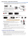
DVS 510 Series • Setup Guide
The Extron DVS 510 Series scalers are 10-input, multi-format presentation switching scalers that accept and scale DVI,
RGB, YUVp/HDTV, YUVi, S-video, and composite video signals to a common high-resolution output rate. Two models are
available: the standard DVS 510, which has fixed and variable line level audio outputs, and the DVS 510 SA, which adds an
integrated stereo amplifier. Control options include front panel buttons and knobs, Ethernet, RS-232 or RS-422, web pages,
and infrared (IR). This guide provides instructions for an experienced installer to install and connect the DVS 510 scalers.
NOTE:
For full installation, configuration, and operation details, see the DVS 510 Series User Guide, available at
www.extron.com.
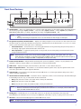
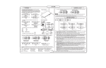
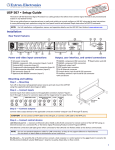
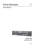
Rear Panel Features and Connections
1
2
6
5
4
3
7
9
8
AMPLIFIED
1
V
I
D
E
O
100-240V
50-60 Hz
2A MAX
3
VID
I
N
P
U
T
2
5
YC
VID
YC
4
A
U
D
I
O
V
I
D
E
O
RGB/R-Y, Y, B-Y
RGB/R-Y, Y, B-Y
6
DVI-I
7/8
DVI-I
9/10
O
U
T
P
U
T
A
U
D
I
O
RGB/R-Y, Y, B-Y
DVI-D
RGB/R-Y, Y, B-Y
I
N
P
U
T
1
L
3
R
L
R
L
2
L
5
R
L
R
L
4
7
R
L
R
L
6
9
R
L
R
L
8
R
10
O
U
T
P
U
T
R
L
R
VARIABLE
L
10
R
FIXED
L
R
11
12
RS232
15
a
b
c
d
e
AC power connector
h
Video inputs 1 and 2: Composite video
i
Video inputs 3 and 4: S-video j
Video inputs 5 and 6: RGB or YUV component
k
Video inputs 7/8 and 9/10: RGB or YUV (7 and 9) and
l
DVI (8 and 10)m
f Buffered RGB/YUV output connectors
n
g DVI-I output connector (digital output only)
o
LAN
RESET
14 13
Audio input connectors
Amplified audio output connector (DVS 510 SA only)
Variable audio output connector
Fixed audio output connector
Reset LED
Reset button
LAN connector
RS-232/RS-422 connector
Installation Steps
1.
Disconnect power from all equipment.
2.
(Optional) Mount the unit. Rack mount the scaler using the
attached brackets (see the illustration at right). For tabletop
placement, remove the brackets from the right and left sides
and attach the provided rubber feet.
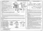
3.
Connect video inputs. Connect video input devices to the
appropriate connectors in the rear panel Video Input section
(b through e in the diagram above).
zz
Video inputs 5 and 6: RGB or YUV component —
Connect one or two RGBHV, RGBS, RGsB, RGBcvS, YUVi,
or YUVp/HDTV video sources to these female 15-pin HD
connectors (shown below). These connectors feature EDID
emulation.
3 2
1
13
14
Inputs 5 and 6
NOTE:
MBD 249
2U Rack Mounting
Bracket (Pre-attached)
(Optional) To obtain one or two more RGB/YUV inputs, you can connect an Extron DVIIM-VGAF/DVIIF
DVI and Analog Breakaway (Y) cable to either or both DVI-I input connectors. Each Y cable provides an
additional RGB VGA connector and DVI-I connector (see ”Breakaway cable” on the next page).
1
DVS 510 Series • Setup Guide (Continued)
zz
Video inputs 7/8 and 9/10 — Connect two DVI video sources, two RGB/YUV sources, or one DVI and one RGB
source to these DVI-I connectors. The analog portions of these connectors are identified as inputs 7 and 9, while the
DVI portions are inputs 8 and 10. These connectors feature EDID emulation.
1
DVI-I Input Connector
C1
Female DVI-I Connector
C2
8
FOR DIGITAL ONLY
C5
9
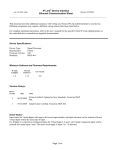
Breakaway cable: You can use an optional Extron
DVIIM-VGAF/DVIIF “Y” DVI adapter cable (shown at
right) to connect one analog RGB or YUV source and
one DVI source to one or both of these connectors.
This cable enables both an analog and a DVI source
device to be connected to these ports and active at
the same time.
Female 15-pin HD Connector
FOR ANALOG ONLY
To an RGB or
YUV Analog
Input Source
Extron
4.
To a DVI
Input Source
DVI-I Male Connector
C3
C4
Analog (Inputs 7 and 9)
17
24
Digital (Inputs 8 and 10)
To DVS 510 Female DVI-I
Input Connector (Inputs 7 – 10)
Connect audio input devices to the Audio Input captive screw connectors (h on the rear panel diagram on the
previous page), as shown below.
R
R
Tip
Sleeve
Tip
Ring
Sleeve (s)
Tip
Ring
L
L
Do not tin the wires!
Tip
Sleeve
Balanced Stereo Input
Unbalanced Stereo Input
5.
Connect video output devices to the Video Output connectors (f and g in the diagram).
6.
Connect audio output devices to the 5-pole Variable (j) and Fixed (k) Audio Output captive screw connectors.
Balanced Audio Output
CAUTION:
Speaker 1
R
R
Tip
NO Ground Here
Sleeve
Tip
NO Ground Here
Speaker 2
L
L
Tip
Ring
Sleeve
Tip
Ring
Do not tin the wires!
Unbalanced Audio Output
For unbalanced audio, connect the sleeves to ground.
DO NOT connect the sleeves to negative (–) contacts.
Audio Output
to Speakers
DVS 510 SA: Connect speakers to the internal amplifier through the 4-pole
Amplified connector (i) (see also the illustration at right).
7.
zz
Connect the red speaker wire to the positive (+) pin on the Amplified connector.
zz
Connect the black speaker wire to the negative (–) pin on the connector.
Connect control devices:
zz
4-pole Captive
Screw Connector
AMPLIFIED
DVS 510 SA
Rear Panel
4/8
Ohms
L
R
LAN Ethernet port — Connect the DVS 510 to an Ethernet LAN or WAN via this RJ-45 connector (n) to control
the scaler from a remote location using an Internet browser on a computer.
zz
RS232 port — For serial RS-232 or RS-422 control, connect a host computer or control system to the DVS via this
9-pin D-sub connector (o).
zz
The front panel has an additional serial port (RS-232 only) (see “Front Panel Features” on the next page).
The default protocol for both ports is 9600 baud, 1 stop bit, no parity, 8 data bits, and no flow control.
8.
Connect power to the DVS 510 by plugging a standard IEC power cord (provided) from a 100 to 240 VAC, 50-60 Hz
power source into the power receptacle (a).
Locking the Front Panel (Executive Mode)
To prevent accidental changes to settings, you can lock the DVS 510 front panel controls by placing the scaler in lock
(executive) mode 1 or 2. While the DVS is in lock mode, RS-232 or RS-422 and IR remote control remain available.
zz
Lock mode 1 locks all front panel functions. This mode can be enabled or disabled only by SIS commands.
zz
Lock mode 2 locks all front panel functions except input selection, PIP, volume control, and Auto-Image™. To enable
lock mode 2, press and hold the Position and Size buttons simultaneously until Executive Mode 2 Enabled appears in
the LCD window (approximately 2 seconds).
To exit lock mode 2, press and hold the Position and Size buttons again until Executive Mode Disabled appears in
the LCD window (approximately 2 seconds).
2
Product Category
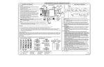
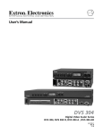
Front Panel Features
1
INPUTS
IR
9
CONFIG
3
2
PIP
1
2
3
4
5
PIP
ON/OFF
6
7
8
9
10
PIP
SWAP
4
5
6
7
ADJUST
VOLUME
PICTURE CONTROLS
SIZE
BRIGHT
/CONT
DETAIL
MENU
POSITION
COLOR
/TINT
ZOOM
/PAN
NEXT
MAX
MID
MIN
8
DVS 510
DIGITAL VIDEO SCALER
a Input Buttons — Press one of these buttons to select an input and switch it to the current output. The inputs support
the following signal types: inputs 1 and 2 — composite video; inputs 3 and 4 — S-video; inputs 5, 6, 7, and 9 —
RGB (RGBHV, RGBS, RGBcvS, or RGsB), YUVp/HDTV, and YUVi; and inputs 8 and 10 — DVI.
NOTES: • On the rear panel, inputs 7 and 8 share one of the DVI-I input connectors; inputs 9 and 10 share the other.
• Pressing and holding the Input button for 3 seconds initiates an Auto-Image on that input.
b PIP (picture-in-picture) control buttons — Display a secondary image from a second source on the screen in front of
the main image, in a previously selected size and position. The default size of the PIP window is one-fourth of the screen
and it is positioned in the lower-right corner of the display.
zz
PIP On/Off button — Turns PIP mode on and off (toggles between showing and hiding the picture-in-picture on
the display). Lights green when the DVS 510 is in PIP mode.
zz
PIP Swap button — Toggles the primary (main or background) and secondary (PIP) pictures between the main
image and the PIP window.
NOTE: When the DVS is in PIP mode, one input must be low-resolution (inputs 1 through 4, and 5, 6, 7, and 9
when they are configured as component video YUVi or RGBcvS) and one must be high-resolution (inputs 5,
6, 7, and 9 when configured as RGB or YUVp/HDTV, and inputs 8 and 10).
c Picture control buttons — Adjust window and image size, position, brightness, contrast, color, tint, detail, zoom
(magnify or reduce), and pan. When one of these buttons is pressed, it lights amber.
d LCD screen — Displays messages, menu information, and menu or control button selections.
e Menu navigation buttons — Press Menu to access the DVS 510 menu system and to step through the menus. From
each menu, press Next to step through the submenus.
f Adjust knobs — Rotate these horizontal ([) and vertical ({) knobs to scroll through submenu and picture control
options and make adjustments.
g Volume knob and indicator LEDs — Rotate this knob to adjust the volume on the current input. The three LEDs light
incrementally, bottom to top, to indicate the current volume level:
zz
Min (green) indicates volume is above 1%. At 0% volume, this LED blinks.
zz
Mid (green) indicates volume above 49%.
zz
Max (red) indicates volume above 79%. At 100% volume, this LED blinks.
NOTES: • The volume level is also shown on the LCD screen as a bar graph.
• When an incremental Volume LED lights, the LEDs below it remain lit. For example, when the Max LED lights, the Mid and Min LEDS are also lit.
h Config port — This RS-232 port on a 2.5 mm TRS connector is an RS-232 only alternative to the rear panel
RS-232/RS-422 port. Default protocol for this port is 9600 baud, 8 data bits,1 stop bit, no parity, and no flow control.
i IR sensor — Receives infrared (IR) signals from the IR 904 remote control.
NOTE:
By default, the IR sensor is disabled.
3
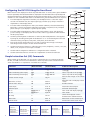
Configuring the DVS 510 Using the Front Panel
Menu selections are displayed on the front panel LCD screen. To use any menu, press the Menu
button repeatedly until the desired menu is displayed. Press the Next button repeatedly until
the desired submenu is displayed. Rotate the appropriate Adjust knob to select an item from a
submenu. To exit a submenu and return to the main menu, press the Menu button at any time.
1.
2.
4.
Use the Input Configuration submenus to make any desired adjustments to the applied
input signals, including turning film mode detection on or off and setting the horizontal
and vertical start, pixel phase, total pixels, active pixels, and active lines.
Input
Configuration
Use the Picture Control buttons to adjust the size, position, brightness, contrast, color, tint,
detail, zoom, and pan for each input as needed.
7.
Use the Audio Configuration submenus to configure the audio as desired.
8.
Use the User Presets menu to save the set of adjustments for manual recall later.
Output
Configuration
30 sec.
Menu
Menu
Audio
Configuration
30 sec.
Menu
Advanced
Configuration
30 sec.
Menu
View
Comm Setting
30 sec.
Menu
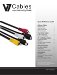
Simple Instruction Set (SIS) Commands
When setting up the DVS 510, you can issue SIS commands from your computer via RS-232,
RS-422, or a LAN connection as an alternative to the front panel controls. See the DVS 510
Series User Guide for a complete list of available SIS commands.
Exit Menu?
Press NEXT
30 sec.
Next
Command
ASCII command
(Host to Scaler)
Response
(Scaler to Host)
Additional Description
Select an audio and video input
X!!
In X! • All ]
Select video and audio from input
source X!.
Audio breakaway (select input)
In X! • Aud ]
Select only audio from input X!.
Video breakaway (select input)
X! $
X! &
In X! • RGB ]
Execute an Auto-Image
A
Img ]
Mute video to black
1B
Vmt1]
Unmute video and sync
0B
Vmt0 ]
Select only video from input X!.
Perform Auto-Image on the current
input.
Mute the video and display a black
screen.
Disable all mutes.
Freeze input
1F
Frz1 ]
Freeze the selected input.
Unfreeze input
0F
Frz0 ]
Unfreeze selected input.
PIP on
E X! PIP }
Pip X! ]
Turn on PIP and display input X!.
PIP off
E 0PIP }
Pip0 ]
Turn off PIP.
PIP Swap
%
Tke ]
Mute audio
1Z
Amt1 ]
Switch the displayed content
between main and PIP windows.
Mute audio for the current input.
Unmute audio
0Z
Amt0 ]
Unmute the current audio input.
Extron USA - West
Headquarters
Extron USA - East
Extron Europe
Extron Asia
Extron Japan
Extron China
Extron Middle East
+800.633.9876
+800.633.9876
+800.3987.6673
+800.7339.8766
Inside Asia Only
+81.3.3511.7655
+81.3.3511.7656 FAX
+400.883.1568
Inside Europe Only
+971.4.2991800
+971.4.2991880 FAX
+1.919.863.1794
+1.919.863.1797 FAX
+31.33.453.4040
+31.33.453.4050 FAX
+65.6383.4400
+65.6383.4664 FAX
Inside USA/Canada Only
+1.714.491.1500
+1.714.491.1517 FAX
4
30 sec.
Menu
Press and hold each input button for 3 seconds to perform Auto-Image on the input.
Auto-Image sizes the input to fit the current window size.
6.
30 sec.
Menu
From the Advanced Configuration menu, Test Pattern submenu, select the Alternating
Pixels (Alt Pixels) test pattern. Adjust the active pixels, total pixels (clock), and pixel
phase settings for your display for optimal picture quality.
From the Advanced Configuration menu, set the test pattern to Crop, and adjust the
position settings of the display until all four sides of the crop pattern are visible. Disable
the Crop test pattern.
5.
User
Presets
From the Output Configuration submenus, use the Adjust knobs to select the output
resolution and refresh rate, the output signal type, and the sync polarity to match the
requirements of the display device.
3.
Default
Cycle
Menu
Inside USA/Canada Only
Inside China Only
+86.21.3760.1568
+86.21.3760.1566 FAX
© 2011 Extron Electronics All rights reserved. www.extron.com
68-1290-50
Rev. A 04 11