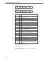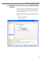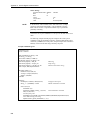
1
HC2S3 Temperature
and Relative
Humidity Probe
User Manual
Issued: 12.12.12
Copyright © 2005-2012 Campbell Scientific Inc.
Printed under Licence by Campbell Scientific Ltd.
CSL 930
Guarantee
This equipment is guaranteed against defects in materials and workmanship.
This guarantee applies for twelve months from date of delivery. We will
repair or replace products which prove to be defective during the guarantee
period provided they are returned to us prepaid. The guarantee will not apply
to:
•
Equipment which has been modified or altered in any way without the
written permission of Campbell Scientific
•
Batteries
•
Any product which has been subjected to misuse, neglect, acts of God or
damage in transit.
Campbell Scientific will return guaranteed equipment by surface carrier
prepaid. Campbell Scientific will not reimburse the claimant for costs incurred
in removing and/or reinstalling equipment. This guarantee and the Company’s
obligation thereunder is in lieu of all other guarantees, expressed or implied,
including those of suitability and fitness for a particular purpose. Campbell
Scientific is not liable for consequential damage.
Please inform us before returning equipment and obtain a Repair Reference
Number whether the repair is under guarantee or not. Please state the faults as
clearly as possible, and if the product is out of the guarantee period it should
be accompanied by a purchase order. Quotations for repairs can be given on
request. It is the policy of Campbell Scientific to protect the health of its
employees and provide a safe working environment, in support of this policy a
“Declaration of Hazardous Material and Decontamination” form will be
issued for completion.
When returning equipment, the Repair Reference Number must be clearly
marked on the outside of the package. Complete the “Declaration of
Hazardous Material and Decontamination” form and ensure a completed copy
is returned with your goods. Please note your Repair may not be processed if
you do not include a copy of this form and Campbell Scientific Ltd reserves
the right to return goods at the customers’ expense.
Note that goods sent air freight are subject to Customs clearance fees which
Campbell Scientific will charge to customers. In many cases, these charges are
greater than the cost of the repair.
Campbell Scientific Ltd,
Campbell Park, 80 Hathern Road,
Shepshed, Loughborough, LE12 9GX, UK
Tel: +44 (0) 1509 601141
Fax: +44 (0) 1509 601091
Email: [email protected]
www.campbellsci.co.uk
PLEASE READ FIRST
About this manual
Please note that this manual was originally produced by Campbell Scientific Inc. primarily for the
North American market. Some spellings, weights and measures may reflect this origin.
Some useful conversion factors:
Area: 1 in2 (square inch) = 645 mm2
Length:
1 in. (inch) = 25.4 mm
1 ft (foot) = 304.8 mm
1 yard = 0.914 m
1 mile = 1.609 km
Mass:
1 oz. (ounce) = 28.35 g
1 lb (pound weight) = 0.454 kg
Pressure:
1 psi (lb/in2) = 68.95 mb
Volume:
1 UK pint = 568.3 ml
1 UK gallon = 4.546 litres
1 US gallon = 3.785 litres
In addition, while most of the information in the manual is correct for all countries, certain information
is specific to the North American market and so may not be applicable to European users.
Differences include the U.S standard external power supply details where some information (for
example the AC transformer input voltage) will not be applicable for British/European use. Please
note, however, that when a power supply adapter is ordered it will be suitable for use in your country.
Reference to some radio transmitters, digital cell phones and aerials may also not be applicable
according to your locality.
Some brackets, shields and enclosure options, including wiring, are not sold as standard items in the
European market; in some cases alternatives are offered. Details of the alternatives will be covered in
separate manuals.
Part numbers prefixed with a “#” symbol are special order parts for use with non-EU variants or for
special installations. Please quote the full part number with the # when ordering.
Recycling information
At the end of this product’s life it should not be put in commercial or domestic refuse
but sent for recycling. Any batteries contained within the product or used during the
products life should be removed from the product and also be sent to an appropriate
recycling facility.
Campbell Scientific Ltd can advise on the recycling of the equipment and in some cases
arrange collection and the correct disposal of it, although charges may apply for some
items or territories.
For further advice or support, please contact Campbell Scientific Ltd, or your local agent.
Campbell Scientific Ltd, Campbell Park, 80 Hathern Road, Shepshed, Loughborough, LE12 9GX, UK
Tel: +44 (0) 1509 601141 Fax: +44 (0) 1509 601091
Email: [email protected]
www.campbellsci.co.uk
Contents
PDF viewers: These page numbers refer to the printed version of this document. Use
the PDF reader bookmarks tab for links to specific sections.
1. Introduction .................................................................. 1
2. Cautionary Statements................................................ 1
3. Initial Inspection .......................................................... 1
4. Quickstart ..................................................................... 2
5. General Description..................................................... 5
6. Specifications .............................................................. 5
6.1 Temperature Sensor ................................................................................. 6
6.2 Relative Humidity Sensor ........................................................................ 6
6.3 Default Settings and Digital Interface ...................................................... 7
7. Installation .................................................................... 7
7.1 Siting ........................................................................................................ 7
7.2 Assembly and Mounting .......................................................................... 8
8. Wiring ........................................................................... 9
9. Example Programs .................................................... 10
9.1 Example Programs using Single-Ended Measurement Instructions ...... 11
9.2 Example Programs using Differential Measurement Instructions.......... 15
10. Measuring Probes with Long Cables ..................... 17
11. Sensor Maintenance ................................................ 18
12. Troubleshooting ...................................................... 18
13. References ............................................................... 19
i
Appendices
A. Absolute Humidity................................................... A-1
A.1 Measurement Below 0°C ..................................................................... A-2
B. Changing the HC2S3 Temperature Range ............ B-1
B.1
B.2
B.3
B.4
HC2S3 Default Settings ....................................................................... B-1
Software and Hardware Requirements ................................................ B-1
Changing the Temperature Range ....................................................... B-2
Multiplier and Offsets for Temperature Range .................................... B-3
C. HC2S3 Digital Communications ............................. C-1
C.1
C.2
C.3
C.4
HC2S3 Digital Interface Specifications ............................................... C-1
HC2S3 Communications Protocol ....................................................... C-1
RS-485 Communications using an MD485 RS-485 Interface ............. C-3
RS-485 Communications using an SDM-SIO1 Serial I/O Module ..... C-5
Figures
7-1. HC2S3 and Met20 Radiation Shield on a vertical pole .......................... 8
Tables
8-1. Connections for Single-Ended Measurements ........................................ 9
8-2. Connections for Differential Measurements ......................................... 10
9-1. Temperature .......................................................................................... 11
9-2. Humidity ............................................................................................... 11
9-3. Wiring for Single-ended Measurement Examples ................................ 12
9-4. Wiring for Differential Measurement Examples ................................... 15
A-1. Wiring for Vapour Pressure Examples............................................... A-1
ii
HC2S3 Temperature and Relative
Humidity Probe
1. Introduction
The HC2S3 is a rugged, accurate temperature/RH probe that is ideal for longterm, unattended applications. The probe uses a Rotronic’s IN1 capacitive
sensor to measure RH and a 100 ohm PRT to measure temperature. For
optimum results, the HC2S3 should be recalibrated annually.
Before using the HC2S3, please study
•
•
•
Section 2, Cautionary Statements
Section 3, Initial Inspection
Section 4, Quickstart
More details are available in the remaining sections.
2. Cautionary Statements
•
Care should be taken when opening the shipping package to not damage or
cut the cable jacket. If damage to the cable is suspected, consult with a
Campbell Scientific applications engineer.
•
Although the HC2S3 is rugged, it should be handled as a precision scientific
instrument.
•
Do not touch the sensor element.
•
The black outer jacket of the cable is Santoprene® rubber. This compound
was chosen for its resistance to temperature extremes, moisture, and UV
degradation. However, this jacket will support combustion in air. It is rated
as slow burning when tested according to U.L. 94 H.B. and will pass
FMVSS302. Local fire codes may preclude its use inside buildings.
3. Initial Inspection
•
Upon receipt of the HC2S3, inspect the packaging and contents for damage.
File damage claims with the shipping company.
•
The model number and cable length are printed on a label at the connection
end of the cable. Check this information against the shipping documents to
ensure the correct product and cable length are received.
•
Refer to the Ships With list to ensure that parts are included (see Section
3.1). The HC2S3 probe and its calibration card are shipped in a small box,
with the box and PN #27731 Hex Plug attached to the cable.
3.1 Ships With
The HC2S3 ships with:
(1) Calibration Card
(1) Resource DVD/CD
1
HC2S3 Temperature and Relative Humidity Probe
4. Quickstart
4.1 Step 1 — Mount the Probe
Review Section 7.2, Installation for complete instructions. The HC2S3 is
normally installed by mounting it inside a Met20 shield.
4.2 Step 2 — Use SCWin Short Cut to Program Datalogger and
Generate Wiring Diagram
The simplest method for programming the datalogger to measure the HC2S3 is
to use Campbell Scientific's SCWin Short Cut Program Generator.
2
1.
Open Short Cut and click on New Program.
2.
Select a datalogger and scan interval.
User Manual
3.
Select HC2S3 Temperature and Relative Humidity Sensor and choose
either constant power or panel switched power (uses less current), then click
the right arrow to add it to the list of sensors to be measured.
4.
Define the name of the public variables. Variables default to AirTC and
RH that hold the air temperature and relative humidity measurements.
Select the desired units of measure. Units default to Deg C.
3
HC2S3 Temperature and Relative Humidity Probe
4
5.
Choose the outputs for the AirTC and RH and then select finish.
6.
Wire according to the wiring diagram generated by SCWin Short Cut.
User Manual
5. General Description
The HC2S3 is a digital probe with 0 to 1 V linear output signals for temperature
and humidity, and a UART serial interface. The voltage signals can be
measured with two single-ended or two differential inputs on the datalogger. A
special Rotronic cable and the SDM-SIO1 Serial I/O Module or MD485 RS-485
Interface is required to interface with the UART as described in Appendix B.
The D/A converter used to generate the analogue output signals has 16-bit
resolution. The default configuration is for temperature -40° to +60°C, and
0 - 100% relative humidity. Temperature range and other default settings can be
changed as described in Appendix A.
A cable ordered through CSI for the HC2S3 includes an internal voltage
regulator that applies 3.3 V to the probe from a 5 to 24 V power source. 12V
power is recommended for use with CSI dataloggers. Where minimizing power
use is important, power can be switched on and off for the measurement
provided there is a 3-second warm-up delay. Switching power avoids the
constant current flow through datalogger ground, which can affect the accuracy
of low level single-ended voltage measurements, primarily with older
dataloggers such as the 21X.
Probes are polarity protected by the keyed connector and a diode in the
connector interface provided with the CSI cable.
CSI offers two filters:
Polyethylene filter: Default filter, protection against fine dust particles,
no water absorption or retention, good response time.
Teflon filter: Recommended for marine environments, slower response
time than the polyethylene filter, ordered separately.
6. Specifications
Operating Limits at Electronics: -40°C to +100°C
Storage Temperature: -50°C to +100°C
Probe Length: 85 mm (3.3 "), 121 mm (4.75”) including connector
Probe Diameter: 15 mm (0.6 ")
Probe Weight: 10 g (0.35 oz)
Filter: Polyethylene or Teflon (optional, ordered separately)
Power Consumption: <4.3 mA @ 5 V
<2.0 mA @ 12 V
Supply Voltage (using CSI cable): 5 to 24 VDC (12 VDC recommended)
Start-up time: 1.5 sec typical (Rotronic specification, CSI recommends 2 sec at
60°C, 3 sec at 0°C, 4 sec at -40°C)
Maximum Startup Current: <50 mA during 2 µs
Maximum Lead Length: 300 m (1000') with 12 V power, 3 m (10') with 5 V
power
Analogue outputs:
Offset at 0 V: ±3 mV (maximum)
Deviation for Digital Signal: < ±1 mV (0.1°C, 0.1% RH)
5
HC2S3 Temperature and Relative Humidity Probe
6.1 Temperature Sensor
Sensor: PT100 RTD, IEC 751 1/3 Class B, with calibrated signal conditioning
Temperature Measurement Range: -50°C to +100°C (default -40°C to + 60°C)
Temperature Output Signal Range: 0 to 1.0 V
Accuracy at 23°C: ±0.1°C with standard configuration settings
Long Term Stability: <0.1°C/year
Sensor Time Constant (63% step change (1 m/sec air flow at sensor)): ≤22 sec
with PE filter, ≤30 sec with Teflon filter
Temperature Accuracy over Temperature:
6.2 Relative Humidity Sensor
Sensor: ROTRONIC Hygromer® IN1
Relative Humidity Measurement Range: 0 to 100% non-condensing
RH Output Signal Range: 0 to 1 VDC
Accuracy at 23°C
±0.8% RH with standard configuration settings
Typical Long Term Stability: <1% RH per year
Sensor Time Constant (63% of a 35 to 80% RH step change (1 m/sec air flow at
sensor)): ≤22 sec with PE filter, ≤30 sec with Teflon filter
6
User Manual
RH Accuracy over Temperature:
CAUTION
The black outer jacket of the cable is Santoprene® rubber.
This compound was chosen for its resistance to temperature
extremes, moisture, and UV degradation. However, this
jacket will support combustion in air. It is rated as slow
burning when tested according to U.L. 94 H.B. and will pass
FMVSS302. Local fire codes may preclude its use inside
buildings.
6.3 Default Settings and Digital Interface
Please refer to Appendices.
7. Installation
7.1 Siting
Sensors should be located over an open level area at least 9 m (EPA) in
diameter. The surface should be covered by short grass, or where grass does not
grow, the natural earth surface. Sensors should be located at a distance of at
least four times the height of any nearby obstruction, and at least 30 m (EPA)
from large paved areas. Sensors should be housed in a suitable radiation shield.
Standard measurement heights:
1.5 m ± 1.0 m (AASC)
1.25 – 2.0 m (WMO)
2.0 m (EPA)
See Section 13 for a list of references that discuss temperature and relative
humidity sensors.
7
HC2S3 Temperature and Relative Humidity Probe
7.2 Assembly and Mounting
Attach the probe to the cable by aligning the keyed connectors, pushing the
connectors together and tightening the knurled ring.
When exposed to solar radiation the probe must be housed in a radiation shield
such as the MET20 or MET21 naturally aspirated shield, or the 43502 motor
aspiration shield (please refer to the 43502 product manual for details). The
MET20/21 Radiation Shield has a V-bolt for attaching the shield to a tripod
mast/tower leg.
To install the probe inside the Radiation Shield, the nut on the base on the shield
should be loosened. Insert the probe into the radiation shield leaving about 5 cm
for the Met20 shield (2 cm for the Met21) exposed below the nut, then tighten
the nut. Route the cable to the datalogger, and secure the cable to the shield arm
and mounting structure using cable ties.
Figure 7-1. HC2S3 and Met20 Radiation Shield on a vertical pole
8
User Manual
8. Wiring
Connections to Campbell Scientific dataloggers for measuring humidity and
temperature using two single-ended or two differential analogue inputs are given
in Tables 8-1 and 8-3. Use a single-ended analogue measurement when the
cable length is less than 6.1 m (20 ft), or if power is switched off between
measurements. For cable lengths longer than 6.1 m or when the probe is
continuously powered, use a differential analogue measurement. See Section 10
for a discussion on errors caused by long cable lengths.
The HC2S3 draws approximately 2 mA powered from 12V. The HC2S3 can be
continuously powered from the 12V terminal, or power can be switched with the
SW12V terminal to conserve battery life. When power is switched, a 3-second
warm-up time is required. Using the SW12V terminal on the CR10X datalogger
requires a user-supplied jumper wire connected between the SW 12V CTRL
terminal and a Control Port (C1..C8).
CAUTION
When measuring the HC2S3 with single-ended
measurements, the yellow and grey leads must both be
connected to AG on the CR10(X) and CR500/CR510 or to
on the CR1000, CR5000, and CR23X. Doing otherwise
will connect the datalogger’s analogue and power ground
planes to each other, which in some cases can cause
offsets on low-level analogue measurements. To avoid
2 mA flowing into analogue ground, switch power on/off for
its measurement.
Table 8-1. Connections for Single-Ended Measurements
Colour
Description
CR1000,
CR3000,
CR800,
CR5000,
CR23X
Brown
Temperature
Signal
Single-Ended
Input
Single-Ended
Input
White
Relative Humidity
Signal
Single-Ended
Input
Single-Ended
Input
Yellow
Signal Reference
AG
Grey
Power Ground
AG
Clear
Shield
G
Green
Power
*CR10X Power Control if
using SW 12V
12V/*SW12V
CR10X,
CR10,
CR510,
CR500
12V/*SW12V
Jumper from
SW 12V
CTRL to
Control Port
9
HC2S3 Temperature and Relative Humidity Probe
Table 8-2. Connections for Differential Measurements
Colour
Description
CR1000,
CR3000,
CR800,
CR5000,
CR23X
Brown
Temperature
Signal
Differential
Input – H
Differential
Input – H
Jumper to
Yellow
Temperature Signal
Reference
Differential
Input – L
Differential
Input – L
White
Relative Humidity Signal
Differential
Input – H
Differential
Input – H
Yellow
Signal Reference
Differential
Input – L
Differential
Input – L
Grey
Power Ground
G
G
Clear
Shield
Green
Power
*CR10X Power Control if
using SW 12V
CR10X,
CR10,
CR510,
CR500
G
12V/*SW12V
12V/*SW12V
Jumper from
SW 12V
CTRL to
Control Port
9. Example Programs
This section is for users who write their own datalogger programs. A datalogger
program to measure this sensor and wiring diagram can be created using
Campbell Scientific’s Short Cut Program Programming Wizard. Short Cut
supports most CSI dataloggers (CR7, 21X, CR10, CR500, CR510, CR23X,
CR3000, CR5000). You do not need to read this section to use Short Cut.
The temperature and relative humidity signals from the HC2S3 can be measured
using a single-ended analogue measurement or a differential analogue
measurement. Differential measurements are recommended for cables longer
than 6.0 m (20') as discussed in Section 10.
The HC2S3 output scale is 0 to 1000 mV for the temperature range of
-40°C to +60°C and 0 to 1000 mV for the relative humidity range of 0 to 100%.
Multipliers and Offsets for the measurement instructions to convert the
measurement result (mV) to temperature and relative humidity are shown in
Tables 9-1 and 9-2.
10
User Manual
Table 9-1. Temperature
Units
Multiplier
(degrees mV-1)
Offset
(degrees)
Celsius
0.1
-40
Fahrenheit
0.18
-40
Table 9-2. Humidity
Units
Multiplier
(% mV-1)
Offset
(%)
Percent
0.1
0
Fraction
0.001
0
9.1 Example Programs using Single-Ended Measurement
Instructions
The example programs for the CR1000 and CR10X use the SW12V terminal to
switch power to the probe, delay for 3 seconds and measure the output voltages
using single-ended measurement instructions.
Relative humidity and temperature (deg C) are measured on single-ended input
channels 1 and 2 respectively. The program sets relative humidity = 100 if the
measured value is > 100 but less than 103%. Values > 103% are not set = 100,
and indicate a problem with the sensor or its calibration.
11
User Manual
Table 9-3. Wiring for Single-ended
Measurement Examples
Colour
Description
CR1000
CR10(X)
Brown
Temperature
SE 2
SE 2
White
Relative Humidity
SE 1
SE 1
Yellow
Signal Reference
AG
Grey
Power Ground
AG
Clear
Shield
G
Green
Power
SW12V
SW12V
Jumper from
SW 12V CTRL
to Control Port
CR1000 program using single-ended measurements
'CR1000 program to measure HC2S3 with single-ended inputs
Public AirTC
Public RH
Units AirTC=Deg C
Units RH=%
DataTable(Table1,True,-1)
DataInterval(0,60,Min,10)
Average(1,AirTC,FP2,False)
Sample(1,RH,FP2)
EndTable
BeginProg
Scan(5,Sec,1,0)
PortSet(9,1)
'Turn on switched 12V
Delay(0,3,Sec)
'3-second delay
'HC2S3 Temperature & Relative Humidity Sensor measurements AirTC and RH:
VoltSE(RH,1,mV2500,1,0,0,_50Hz,0.1,0)
VoltSe(AirTC,1,mV2500,2,0,0,_50Hz,0.1,-40)
PortSet(9,0)
'Turn off switched 12V
If RH>100 AND RH<103 Then RH=100
CallTable(Table1)
NextScan
EndProg
12
User Manual
CR10(X) program using single-ended measurement instructions
;{CR10X} program to measure HC2S3 with single-ended inputs
*Table 1 Program
01: 5.0000
Execution Interval (seconds)
1: Do (P86)
1: 41
Set Port 1 High
;Turn on switched 12V
;Jumper from C1 to SW 12V CTRL
2: Excitation with Delay (P22)
;3-second delay
1: 1
Ex Channel
2: 0
Delay W/Ex (0.01 sec units)
3: 300
Delay After Ex (0.01 sec units)
4: 0
mV Excitation
;HC2S3 Temperature & Relative Humidity Sensor measurements AirTC and RH:
3: Volt (SE) (P1)
1: 1
2: 35
3: 2
4: 2
5: 0.1
6: -40.0
Reps
2500 mV 50 Hz Rejection Range
SE Channel
Loc [ AirTC ]
Multiplier
Offset
4: Volt (SE) (P1)
1: 1
2: 35
3: 4
4: 1
5: 0.1
6: 0
Reps
2500 mV 50 Hz Rejection Range
SE Channel
Loc [ RH ]
Multiplier
Offset
5: Do (P86)
1: 51
Set Port 1 Low
;Turn off switched 12V
6: If (X<=>F) (P89)
1: 1
X Loc [ RH ]
2: 3
>=
3: 100
F
4: 30
Then Do
7: If (X<=>F) (P89)
1: 1
X Loc [ RH ]
2: 4
<
3: 103
F
4: 30
Then Do
8: Z=F x 10^n (P30)
1: 100
F
2: 0
n, Exponent of 10
3: 1
Z Loc [ RH ]
9: End (P95)
10: End (P95)
11: If time is (P92)
13
HC2S3 Temperature and Relative Humidity Probe
1:
2:
3:
0
60
10
Minutes (Seconds --) into a
Interval (same units as above)
Set Output Flag High (Flag 0)
12: Set Active Storage Area (P80)
1: 1
Final Storage Area 1
2: 101
Array ID
13: Real Time (P77)
1: 1220
Year,Day,Hour/Minute (midnight = 2400)
14: Average (P71)
1: 1
Reps
2: 2
Loc [ AirTC ]
15: Sample (P70)
1: 1
2: 1
Reps
Loc [ RH ]
CR1000 program using single-ended measurements in Slow Sequence scan
HC2S3 measurements are made every 5 seconds in a Slow Sequence scan. Multiple 500 mSec delays
are used for the 3 second warm-up time, which allows the 1 second scan to occur between Delay
instructions.
'CR1000 program
Public AirTC
Public RH
Public Battery_volts, Ptemp_C
Units AirTC=Deg C
Units RH=%
DataTable(Table1,True,-1)
DataInterval(0,60,Min,10)
Average (1,Battery_volts,FP2,False)
Average (1,Ptemp_C,FP2,False)
Average(1,AirTC,FP2,False)
Sample(1,RH,FP2)
EndTable
BeginProg
Scan(1,Sec,1,0)
'measurements to be made every 1 second
Battery (Battery_volts)
PanelTemp (Ptemp_C,250)
'add additional instructions to be executed every 1 second
CallTable(Table1)
NextScan
14
User Manual
SlowSequence
'measure HC2S3 every 5 seconds
Scan (5,Sec,0,0)
'HC2S3 Temperature & Relative Humidity
`Note this forces and only works in sequential mode
`Contact Campbell Scientific if your program must work in pipeline mode
SW12(1) `switch on 12V
Delay(1,3000,mSec) `delays for 3 seconds
VoltSe(AirTC,1,mV2500,2,0,0,_50Hz,0.1,-40) `measure probe
VoltSe(RH,1,mV2500,1,0,0,_50Hz,0.1,0)
SW12(0) `switch off 12V
If RH>100 AND RH<103 Then RH=100
NextScan
EndProg
9.2 Example Programs using Differential Measurement
Instructions
Temperature and humidity are measured on differential input channels 1 and 2
respectively. The program sets relative humidity = 100 if the measured value is
> 100 but less than 103%. Values > 103% are not set = 100, and indicate a
problem with the sensor or its calibration.
Table 9-4. Wiring for
Differential Measurement Examples
Colour
Description
CR1000
CR10(X)
Brown
Temperature
1H
1H
Jumper to
Yellow
Temperature Signal
Reference
1L
1L
White
Relative Humidity
2H
2H
Yellow
Signal Reference
2L
2L
Grey
Power Ground
G
G
Clear
Shield
Green
Power
G
12V
12V
For these examples the sensor is powered on continuously.
15
HC2S3 Temperature and Relative Humidity Probe
CR1000 program using differential measurements
'CR1000 program to measure HC2S3 with differential measurements
Public AirTC
Public RH
DataTable(Temp_RH,True,-1)
DataInterval(0,60,Min,0)
Average(1,AirTC,IEEE4,0)
Sample(1,RH,IEEE4)
EndTable
BeginProg
Scan(1,Sec,1,0)
'HC2S3 Temperature & Relative Humidity Sensor measurements AirTC and RH:
VoltDiff (AirTC,1,mV2500,1,True,0,_50Hz,0.1,-40)
VoltDiff (RH,1,mV2500,2,True,0,_50Hz,0.1,0)
If RH>100 And RH<103 Then RH=100
CallTable(Temp_RH)
NextScan
EndProg
CR10(X) program using differential measurement instructions
;{CR10X}
*Table 1 Program
01: 1.0000
Execution Interval (seconds)
;HC2S3 Temperature & Relative Humidity Sensor measurements AirTC and RH:
1: Volt (Diff) (P2)
1: 1
2: 35
3: 1
4: 3
5: 0.1
6: -40
Reps
2500 mV 50 Hz Rejection Range
DIFF Channel
Loc [ AirTC ]
Multiplier
Offset
2: Volt (Diff) (P2)
1: 1
2: 35
3: 2
4: 4
5: 0.1
6: 0
Reps
2500 mV 50 Hz Rejection Range
DIFF Channel
Loc [ RH ]
Multiplier
Offset
3: If (X<=>F) (P89)
1: 4
X Loc [ RH ]
2: 3
>=
3: 100
F
4: 30
Then Do
16
User Manual
4: If (X<=>F) (P89)
1: 4
X Loc [ RH ]
2: 4
<
3: 103
F
4: 30
Then Do
5: Z=F x 10^n (P30)
1: 100
F
2: 0
n, Exponent of 10
3: 4
Z Loc [ RH ]
6: End (P95)
7: End (P95)
8: If time is (P92)
1: 0
Minutes (Seconds --) into a
2: 60
Interval (same units as above)
3: 10
Set Output Flag High (Flag 0)
9: Set Active Storage Area (P80)
1: 1
Final Storage Area 1
2: 101
Array ID
10: Real Time (P77)
1: 1220 Year,Day,Hour/Minute (midnight = 2400)
11: Average (P71)
1: 1 Reps
2: 3 Loc [ AirTC ]
12: Sample (P70)
1: 1 Reps
2: 4 Loc [ RH ]
10. Measuring Probes with Long Cables
For cable lengths longer than 6.1 m (20'), CSI recommends measuring the
voltage signals using differential inputs as discussed below. Connections for
differential inputs are given in Table 8-2.
The signal reference (yellow) and the power ground (grey) are in common inside
the HC2S3. When the HC2S3 temperature and relative humidity are measured
using a single-ended analogue measurement, both the signal reference and
power ground are connected to ground at the datalogger. The signal reference
and power ground both serve as the return path for power. There will be a
voltage drop along those leads because the wire itself has resistance.
The HC2S3 draws approximately 2 mA when powered with 12V. The wire
used in the HC2S3 (P/N #27746) has resistance of 14.74 Ω/304.8 m (1000').
Since the signal reference and the power ground are both connected to ground at
the datalogger, the effective resistance of those wires together is half of
14.74 Ω/304.8 m (1000'), or 7.37 Ω/304.8 m (1000'). Using Ohm’s law, the
voltage drop (Vd), along the signal reference/power ground, is given by Eq. (1).
17
HC2S3 Temperature and Relative Humidity Probe
Vd
= I ∗R
= 2 mA ∗ 7.37 Ω 304.8 m (1000 ' )
(1)
= 14.7 mV 304.8 m (1000 ' )
This voltage drop will raise the apparent temperature and relative humidity
because the difference between the signal and signal reference lead, at the
datalogger, has increased by Vd. The approximate error in temperature and
relative humidity is 0.15°C and 0.15% per 30.5 m (100') of cable length,
respectively (assuming a temperature range of -40° to +60°C). When there are
not enough inputs available on the datalogger to allow for differential
measurements, single-ended measurements can be made and the errors
associated with cable length subtracted as offsets.
11. Sensor Maintenance
Corroded, discoloured or clogged filters should be replaced. To replace the
filter, unscrew the filter from the probe and pull it straight away, being careful
not to bend or damage the sensors. Before putting on the replacement filter
check the alignment of the sensors with the probe, and if necessary, carefully
correct the alignment before installing the filter.
The Teflon filter tip is recommended when the sensor is installed in close
proximity to the ocean or other bodies of salt water. A coating of salt (mostly
NaCl) may build up on the radiation shield, sensor, filter and even the sensors.
A build-up of salt on the filter or sensors will delay or destroy the response to
atmospheric humidity.
Long term exposure of the relative humidity sensor to certain chemicals and
gases may affect the characteristics of the sensor and shorten its life. The
resistance of the sensor depends strongly on the temperature and humidity
conditions and the length of the pollutant influence.
In general, the HC2S3 requires minimal maintenance. The radiation shield
should be kept clean and free of debris, and the sensor should be calibrated
annually. Please obtain an RMA number before returning the HC2S3 to
Campbell Scientific for calibration. Please refer to Guarantee section at the
beginning of the manual.
12. Troubleshooting
Symptom: -9999, NAN, -40°C, or 0 % relative humidity
18
1.
Check that the sensor is wired to the correct analogue input channels as
specified by the measurement instructions.
2.
Verify the voltage range code for the single-ended or differential
measurement instruction is correct for the datalogger type.
3.
Verify the green power wire is connected to the 12V, SW12V, or 5V
terminal. When SW12V is used with a CR10X datalogger, verify the
SW 12V CTRL is jumpered to the Control Port specified in the program.
Cables longer than 3 m (10') should be powered by the 12V, rather than the
5V terminal.
User Manual
A voltmeter can be used to check the output voltage for temperature and
relative humidity on the brown and white wires respectively (temperature
°C = mV * 0.1 – 40.0; relative humidity % = mV * 0.1).
Symptom: Incorrect temperature or relative humidity
1.
Verify the multiplier and offset parameters are correct for the desired units
(Table 9-1) and temperature range.
2.
Default settings are listed in Appendix A, which include the setting “Limit
humidity output to 100%”. This setting is “disabled” for probes purchased
through CSI. Accuracy of the humidity measurement over temperature is
shown in the graph in Section 2.2. For example, at -20°C the accuracy is
±2.3%, so a reading of 102.3% at 100% humidity is within the accuracy
specification. Programs created by Short Cut set humidity values >100%
and <103% to 100%. Humidity values >103% are left unchanged to
indicate a problem with the probe or measurement.
13. References
AASC, 1985: The State Climatologist (1985) Publication of the American
Association of State Climatologists: Heights and Exposure Standards for
Sensors on Automated Weather Stations, v. 9, No. 4 October, 1985.
(www.stateclimate.org/publications/state-climatologist/NOAA-NCYSCBOOKS-SC77097/00000029.pdf)
EPA, 2000: Meteorological Monitoring Guidance for Regulatory Modelling
Applications, EPA-454/R-99-005. Office of Air Quality Planning and
Standards, Research Triangle Park, North Carolina 27711.
EPA, 2008: Quality Assurance Handbook for Air Pollution Measurement
Systems, Vol. IV, Meteorological Measurements, Ver. 2.0, EPA-454/B-08002 (revised 2008). Office of Air Quality Planning and Standards, Research
Triangle Park, NC 27711.
Goff, J. A. and S. Gratch, 1946: Low-pressure properties of water from -160°
to 212°F, Trans. Amer. Soc. Heat. Vent. Eng., 51, 125-164.
Lowe, P. R., 1977: An approximating polynomial for the computation of
saturation vapour pressure, J. Appl. Meteor., 16, 100-103.
Meyer, S. J. and K. G. Hubbard, 1992: Nonfederal Automated Weather Stations
and Networks in the United States and Canada: A Preliminary Survey,
Bulletin Am. Meteor. Soc., 73, No. 4, 449-457.
Weiss, A., 1977: Algorithms for the calculation of moist air properties on a
hand calculator, Amer. Soc. Ag. Eng., 20, 1133-1136.
WMO, 2008. Guide to Meteorological Instruments and Methods of Observation.
World Meteorological Organization No. 8, 7th edition, Geneva, Switzerland.
19
Appendix A. Absolute Humidity
The HC2S3 measures the relative humidity. Relative humidity is defined by the
equation below:
RH =
e
∗ 100
es
(A-1)
where RH is the relative humidity, e is the vapour pressure in kPa , and es is the
saturation vapour pressure in kPa. The vapour pressure, e, is an absolute
measure of the amount of water vapour in the air and is related to the dew point
temperature. The saturation vapour pressure is the maximum amount of water
vapour that air can hold at a given air temperature. The relationship between
dew point and vapour pressure, and air temperature and saturation vapour
pressure are given by Goff and Gratch (1946), Lowe (1977), and Weiss (1977).
Relative Humidity is relative to saturation above water, even below freezing
point. This is why these sensors should not measure 100% RH below zero
degrees C, as described in Section A.1.
When the air temperature increases, so does the saturation vapour pressure.
Conversely, a decrease in air temperature causes a corresponding decrease in
saturation vapour pressure. It follows then from Eq. (A-1) that a change in air
temperature will change the relative humidity, without causing a change in
absolute humidity.
For example, for an air temperature of 20°C and a vapour pressure of 1.17 kPa,
the saturation vapour pressure is 2.34 kPa and the relative humidity is 50%. If
the air temperature is increased by 5°C and no moisture is added or removed
from the air, the saturation vapour pressure increases to 3.17 kPa and the relative
humidity decreases to 36.9%. After the increase in air temperature, there is
more energy to vaporize the water. However, the actual amount of water vapour
in the air has not changed. Thus, the amount of water vapour in the air, relative
to saturation, has decreased.
Because of the inverse relationship between relative humidity and air
temperature, finding the mean relative humidity is often not useful. A more
useful quantity is the mean vapour pressure. The mean vapour pressure can be
computed by the datalogger program as shown in the following example.
Table A-1. Wiring for Vapour Pressure
Examples
Colour
Description
CR1000
Brown
Temperature
SE 2
White
Relative Humidity
SE 1
Yellow
Signal Reference
Grey
Power Ground
Clear
Shield
Green
Power
12V
A-1
Appendix A. Absolute Humidity
CR1000 Program that Computes Vapour Pressure and Saturation Vapour Pressure
'CR1000 program that calculates Vapour Pressure
Public AirTC
Public RH
Public RH_Frac, e_Sat, e_kPa
DataTable(Temp_RH,True,-1)
DataInterval(0,60,Min,0)
Average(1,AirTC,IEEE4,0)
Sample(1,RH,IEEE4)
Sample(1,e_kPa,IEEE4)
EndTable
BeginProg
Scan(1,Sec,1,0)
PortSet(9,1)
'Turn on switched 12V
Delay(0,3,Sec)
'3-second delay
'HC2S3 Temperature & Relative Humidity Sensor measurements AirTC and RH:
VoltSE(AirTC,1,mV2500,2,0,0,_60Hz,0.1,-40.0)
VoltSE(RH,1,mV2500,1,0,0,_60Hz,0.1,0)
If RH>100 And RH<103 Then RH=100
PortSet(9,0)
'Turn off switched 12V
'Calculate Vapour Pressure
'Convert RH percent to RH Fraction
RH_Frac = RH * 0.01
'Calculate Saturation Vapour Pressure
SatVP(e_Sat, AirTC)
'Compute Vapour Pressure, RH must be a fraction
e_kPa = e_Sat * RH_Frac
CallTable(Temp_RH)
NextScan
EndProg
A.1 Measurement Below 0°C
The HC2S3 provides a humidity reading that is referenced to the saturated water
vapour pressure above liquid water, even at temperatures below 0°C, where ice
might form. This is the common way to express relative humidity and is as
defined by the World Meteorological Organization. If an RH value is required
referenced to ice, the HC2S3 readings will need to be corrected.
One consequence of using water as the reference is that the maximum humidity
that will normally be output by the sensor for temperatures below freezing is as
follows:
100%RH at 0°C
95%RH at -5°C
91%RH at -10°C
87%RH at -15°C
82%RH at -20°C
78%RH at -25°C
75%RH at -30°C
In practical terms this means that, for instance, at -20°C the air is effectively
fully saturated when the sensor outputs 82%RH.
A-2
Appendix B. Changing the HC2S3
Settings
B.1 HC2S3 Default Settings
The HC2S3 probe has the following default settings, which can be changed as
described in the following sections. Additional information can be found in
Rotronic’s User Manual: E-M-HC2 Probes-VXXXX, which can be downloaded
from Rotronic's website www.rotronic-usa.com.
Default Settings:
Configurable Settings
Unit system (Metric or English)
Psychrometric calculation
Output 1 parameter, scale and unit
Output 2 parameter, scale and unit
Communications Protocol
RS-485 Address
Device name
Humidity / temperature adjustment
Device write protection
Limit humidity output to 100% RH
Out-of-limit value digital alarm
Data recording
Automatic humidity sensor test
Humidity sensor drift compensation
Fail safe mode
Simulator mode
Factory Default
Metric
None
Humidity: 0..100% RH
Temperature: -40...+60 deg C
RO-ASCII
0
Probe type
Disabled
Disabled
Disabled
Enabled (loop mode - 10 min interval)
Disabled
Disabled
Disabled
Disabled
Digital Interface:
Interface Type: UART (Universal Asynchronous Receiver Transmitter)
Organization: Dialog, duplex
Default Configuration:
Baud rate: 19200
Parity: none
Data bits: 8
Stop fits: 1
Flow Control: none
Logical Levels:
Logical 0: <= 0.3V*VDD
Logical 1: <= 0.8V*VDD
B.2 Software and Hardware Requirements
For temperature (Analogue Output 2), the HC2S3 default range is -40 to +60°C
for 0 to 1V. Changing the range requires Rotronic HW4 Software (Version
2.1.0 or higher), and the Rotronic model AC3001 USB adapter cable. Power to
the probe is provided by the USB port.
B-1
Appendix B. Changing the HC2S3 Settings
IMPORTANT
Prior to using the AC3001 cable, the ROTRONIC USB driver
must be installed on the PC. Both the driver and the installation
instructions (document E-M-HW4v3-Main) are located on the
HW4 CD.
B.3 Changing the Temperature Range
Install the HW4 software and drivers for the AC3001 USB cable on the PC.
Connect the HC2S3 probe to the AC3001 cable, making sure the connectors are
properly aligned before tightening the knurled ring. Plug the AC3001 cable into
a USB port on the computer.
From the main screen, click on the “devices and groups”, search for “master
devices”, USB masters.
HW4 should find the probe, and show the current values:
B-2
Appendix B. Changing the HC2S3 Settings
Click on “Device Manager”, select “Analogue Outputs” to see the following
screen:
Change the lower and upper range values and click “OK”. The following screen
shows the range -60 to +30:
B.4 Multiplier and Offsets for Temperature Range
Analogue Output 2 is 0 to 1V (1000 mV) for the temperature range. If the range
has been changed from the default (-40 to +60), then the multiplier and offset for
the measurement instruction will have to be changed from those shown for the
program examples in Section 5. For example, for a range of -60 to 30, the
multiplier to convert the measurement result ( mV) to temperature, is the full
scale range of temperature divided by the full scale range of mV, and the Offset
is -60.0 as shown below:
Multiplier = mV * (90°C/1000 mV)
= 0.09
Offset
= -60.0
B-3
Appendix B. Changing the HC2S3 Settings
Example measurement instructions for CR1000 datalogger, with the sensor
wired to SE channel 2:
Public AirTC
VoltSe (AirTC,1,mV2500,2,0,0,_60Hz,0.09,-60)
Example measurement instruction for CR10X datalogger:
1: Volt (SE) (P1)
1: 1
2: 5
3: 2
4: 1
5: 0.09
6: -60.0
B-4
Reps
2500 mV Slow Range
SE Channel
Loc [ AirTC ]
Multiplier
Offset
Appendix C. HC2S3 Digital
Communications
C.1 HC2S3 Digital Interface Specifications
The HC2S3 has a UART (Universal Asynchronous Receiver Transmitter) that
provides two-way digital communications with the probe. Interface cables can
be ordered through Rotronics for connecting the probe to an RS-485 port
(Rotronic pn E2-05XX-MOD), a computer's RS-232 port (Rotronic
pn AC3002), or USB port (Rotronic pn AC3001).
Connections to a CSI datalogger through an MD485 RS485 Interface or
SDM-SIO1 Serial I/O Module with the Rotronic E2-05XX-MOD RS-485 cable
are described in Section C.3 and C.4 respectively.
HC2S3 Digital Interface Specifications:
Interface Type: UART (Universal Asynchronous Receiver Transmitter)
Organization: Dialog, duplex
Default Configuration:
Baud rate: 19200
Parity: none
Data bits: 8
Stop fits: 1
Flow Control: none
Logical Levels:
Logical 0: <= 0.3V*VDD
Logical 1: <= 0.8V*VDD
C.2 HC2S3 Communications Protocol
Complete information on the HC2S3 Commands and Communication Protocol
can be found in the Rotronic E-M-AC3000-CP_XX manual, available from
Rotronic's website www.rotronic-usa.com.
The “RDD” command to “Read Values” is used in the example datalogger
programs to get temperature and relative humidity values from the probe, and is
described below.
RDD command: read values
Returns the measured and calculated values as well as the information necessary
to interpret the data (calculated parameter type, engineering units, status, serial
number and name of the device, etc.)
C-1
Appendix C. HC2S3 Digital Communications
Command Format:
{
ID
Adr
RDD
Chksum or }
CR
Adr
RDD
Chksum or }
CR
Answer format:
{
ID
The data are returned according to the following structure:
Example
Type
Description
1..3
Byte
Probe type (1= digital probe, 2=analogue probe,
3=pressure probe)
1234.56
Float
Relative humidity or analogue value
%RH
String
Humidity or analogue value engineering unit
0..1
Bool
Humidity or analogue value alarm (out-of-limits)
+
Char
Humidity or analogue value trend (+,-,= or “ “)
1234.56
Float
Temperature value
°C
String
Temperature engineering unit
0..1
Bool
Temperature alarm (out-of-limits)
=
Char
Temperature trend (+,-,= or “ “)
Dp
String
Calculated parameter type (nc: no calculation, Dp:
dew point, Fp: frost point)
1234.56
Float
Calculated numerical value
°C
String
Calculated parameter engineering unit
0..1
Bool
Calculated parameter alarm (out-of-limits)
+
Char
Calculated parameter trend (+,-,= or “ “)
1..255
Byte
Device type (HygroClip, Logger, HF, HM, …)
V1.0
String
Firmware version
12345678
String
Device serial number
Name
String
Device name
000…255
Byte
Alarm Byte: (Bit0=out-of-limits value, Bit5= sensor
quality, Bit6 = humidity simulator, Bit7= temperature
simulator)
Example data returned from the RDD command:
{F00RDD} CR
{F00rdd 001; 4.45;%RH;000;=; 20.07;°C;000;=;nc;---.-;°C;000; ;001;V1.71;0060568338;HC2-S3 ;000;4
C-2
Appendix C. HC2S3 Digital Communications
C.3 RS-485 Communications using an MD485 RS-485
Interface
The HC2S3 can be interfaced to a CSI datalogger through an MD485 RS-485
Interface using the Rotronic E2-05XX-MOD RS485 cable as described below.
Settings for the RS485 port on the MD485 must be configured to match the
configuration of the HC2S3, which are 19200 baud, No Parity, 8 Data Bits,
1 Stop bit, and No Flow Control.
Device Configuration Utility (CSI software available as a free download) is used
to configure the MD485. Configuration settings for the MD485 are shown
below:
MD485 Tab: CS I/O AND RS-485
CS I/O Tab: SDC Address 7
RS485 Tab: RS485 baud 19200
C-3
Appendix C. HC2S3 Digital Communications
Sensor Wiring:
E2-05XX-MOD Cable MD485
Blue
A
Red
B
Green
Grey/Yellow
Clear
NOTE
CR1000
12V
G
Ground Symbol
If the Rotronic cable includes brown and white wires (voltage
signals for temperature and humidity), CSI recommends “capping”
them with PN #27749 or equivalent insulated caps to prevent the
possibility of shorting.
Connect the CS I/O port of MD485 to CS I/O port on CR1000 with an SC12
cable.
The following example CR1000 program configures the CS I/O port as
COMSDC7 using the SerialOpen instruction, sends the RDD (Read Values)
command “|{F00RDD}CR” to the probe, and parses temperature and relative
humidity values from the data string returned by the probe.
Example CR1000 Program:
'CR1000 Program
'Declare variables
Public SerialIndest As String * 100
Dim String_1 As String
Const CRLF=CHR(13)+CHR(10)
Dim HC2S3_Split(17) As String * 40
Alias HC2S3_Split(2) = RH_Str
Alias HC2S3_Split(6) = TempC_Str
Alias HC2S3_Split(17) = HC2S3_SN_Str
Public TempC, RH, NBytesReturned
'RH string.
'Temp string.
'HC2S3 serial number string.
DataTable (Table1,1,-1)
DataInterval (0,15,Min,10)
Average (1,TempC,FP2,False)
Sample (1,RH,FP2)
EndTable
BeginProg
SerialOpen (ComSDC7,19200,0,0,100)
String_1 = "|{F00RDD}"+CRLF
'Configure CS I/O port
'RS485 command to send data
Scan (5,Sec,0,0)
SerialFlush (34)
SerialOut (ComSDC7,String_1,0,2,100)
'Send command to send data
Delay (0,500,mSec)
'Get data from probe
SerialInRecord (ComSDC7,SerialIndest,&H6464,0,&H3B48,NBytesReturned,01)
'Parse RH and temp from string
SplitStr (HC2S3_Split(),SerialIndest,";",17,7)
C-4
Appendix C. HC2S3 Digital Communications
RH=RH_Str
TempC=TempC_Str
CallTable Table1
NextScan
EndProg
C.4 RS-485 Communications using an SDM-SIO1
Serial I/O Module
The HC2S3 can be interfaced to a CSI datalogger through an SDM-SIO1 Serial
I/O Module using the Rotronic E2-05XX-MOD RS485 cable as described
below.
The example program uses the SerialOpen instruction to configure the SDMSIO1 for RS-485 half duplex, “COMport 32” at 19200 baud, no parity, 1 stop
bit, and 8 data bits, and serial instructions to send the RDD command to get
temperature and relative humidity data from the probe.
Sensor Wiring:
E2-05XX-MOD Cable
Blue
Red
Grey/Yellow
Green
Clear
SDM-SIO1 CR1000
Z
Y
G
12V
Ground
SDM-SIO1 Wiring:
SDM-SIO1
CR1000
C1
C1
C2
C2
C3
C3
G
G
12V
12V
NOTE
If the Rotronic cable includes brown and white wires (voltage
signals for temperature and humidity), CSI recommends “capping”
them with PN #27749 or equivalent insulated caps to prevent the
possibility of shorting.
C-5
Appendix C. HC2S3 Digital Communications
Example CR1000 Program:
'CR1000 Program
'Declare variables
Public SerialIndest As String * 100
Dim String_1 As String
Const CRLF=CHR(13)+CHR(10)
Dim HC2S3_Split(17) As String * 40
Alias HC2S3_Split(2) = RH_Str
Alias HC2S3_Split(6) = TempC_Str
Alias HC2S3_Split(17) = HC2S3_SN_Str
Public TempC, RH, NBytesReturned
Const SensorPort=32
'RH string.
'Temp string.
'HC2S3 serial number string.
'SDM-SIO1 rotary switch set at 0
DataTable (Table1,1,-1)
DataInterval (0,15,Min,10)
Average (1,TempC,FP2,False)
Sample (1,RH,FP2)
EndTable
BeginProg
SerialOpen (SensorPort,19200,51,100,200)
String_1 = "|{F00RDD}"+CRLF
'51 is for half duplex
'RS485 command to send data
Scan (5,Sec,0,0)
SerialFlush (SensorPort)
SerialOut (SensorPort,String_1,0,1,100)
'Send command to send data
Delay (0,500,mSec)
'Get data from probe
SerialInRecord (ComSDC7,SerialIndest,&H6464,0,&H3B48,NBytesReturned,01)
'Parse RH and temp from string
SplitStr (HC2S3_Split(),SerialIndest,";",17,7)
RH=RH_Str
TempC=TempC_Str
CallTable Table1
NextScan
EndProg
C-6
CAMPBELL SCIENTIFIC COMPANIES
Campbell Scientific, Inc. (CSI)
815 West 1800 North
Logan, Utah 84321
UNITED STATES
www.campbellsci.com • [email protected]
Campbell Scientific Africa Pty. Ltd. (CSAf)
PO Box 2450
Somerset West 7129
SOUTH AFRICA
www.csafrica.co.za • [email protected]
Campbell Scientific Australia Pty. Ltd. (CSA)
PO Box 8108
Garbutt Post Shop
QLD 4814 AUSTRALIA
www.campbellsci.com.au • [email protected]
Campbell Scientific do Brazil Ltda. (CSB)
Rua Luisa Crapsi Orsi, 15 Butantã
CEP: 005543-000 São Paulo SP BRAZIL
www.campbellsci.com.br • [email protected]
Campbell Scientific Canada Corp. (CSC)
11564 - 149th Street NW
Edmonton, Alberta T5M 1W7
CANADA
www.campbellsci.ca • [email protected]
Campbell Scientific Centro Caribe S.A. (CSCC)
300N Cementerio, Edificio Breller
Santo Domingo, Heredia 40305
COSTA RICA
www.campbellsci.cc • [email protected]
Campbell Scientific Ltd. (CSL)
Campbell Park
80 Hathern Road
Shepshed, Loughborough LE12 9GX
UNITED KINGDOM
www.campbellsci.co.uk • [email protected]
Campbell Scientific Ltd. (France)
3 Avenue de la Division Leclerc
92160 ANTONY
FRANCE
www.campbellsci.fr • [email protected]
Campbell Scientific Spain, S. L.
Avda. Pompeu Fabra 7-9
Local 1 - 08024 BARCELONA
SPAIN
www.campbellsci.es • [email protected]
Campbell Scientific Ltd. (Germany)
Fahrenheitstrasse13, D-28359 Bremen
GERMANY
www.campbellsci.de • [email protected]
Please visit www.campbellsci.com to obtain contact information for your local US or International representative.