1
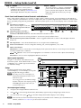
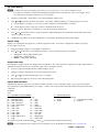
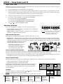
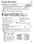
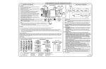
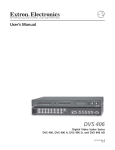
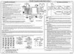
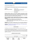
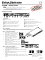
IN1508 – Setup Guide
N For full installation, configuration, and operation details, refer to the
IN1508 User’s Manual, available at www.extron.com.
This guide provides quick start instructions for an experienced installer to set up and
operate the Extron IN1508 Scaling Presentation Switcher.
Installation and cabling
100-240V
50-60Hz
I
1
VID
3
6
YC
VID
U
1
T
U S 1T23
OUTPUT
1
RGB
Y, B-Y, R-Y
OUTPUT
AUDIO INPUT
I.T.E.
RGB
P
50/60Hz
LISTED
C
N
2
3
4
5
L
7
4
2
3
Y
B-Y
5
4
R-Y
RGB
7
5
DVI
8
L
RS-232
B
R
R
R
2
A
6
L
YC
8
6
7
8
9
10 11
12
Connections
a AC power connector
b Inputs 1 and 2 composite video BNC connectors
c Inputs 3 and 4 S-video mini-DIN connectors
d Input 5 component video BNC connectors
e Inputs 6 and 7 RGB video 15-pin HD connectors
f Input 8 DVI video connector (DVI-D only)
g Output 15-pin HD connector
h Audio Inputs 1 through 5 RCA connectors
i Audio Inputs 6 through 8 3.5 mm mini stereo jacks
j Audio Output A RCA connectors
k Audio Output B captive screw connector
l RS-232 9-pin D connector
Step 1 — Mounting
Turn off or disconnect all equipment power sources. For tabletop use, affix the rubber feet. For
optional rack mounting, secure the supplied brackets (see image at right) and mount in a rack.
UT
TP
Step 2 — Video inputs and output
a. Inputs 1 and 2 — Connect composite video
sources to these female BNC connectors.
b.
Inputs 3 and 4 — Connect S-video sources
to these 4-pin mini DIN connectors.
OU
A
B
L
Input 5 — Connect a component video
(YUVi, YUVp, HDTV) source to these
female BNC connectors.
5
8
R
7
AU
I
1
3
VID
YC
U S I.T.E
P
VID
YC
B
Input 8 — Connect a single link of DVI-D video
to this DVI-I connector.
2
Output — Connect an RGB or component video
display to this 15-pin HD output female connector.
Step 3 — Audio inputs and outputs
DV
7
RG
Y
C-
Y
e.
L
R
I
B
RG
3 YC
1 VID
4
z
60H
500V
-24
100
Y
B-
I
N
B-Y
5
5
Y
VID
P
4
U
Inputs 6 and 7 — Connect RGB video sources to
these 15-pin HD connectors.
B
RG CY,
B-
Y
Y,
C
6
U
T
UT
TP
OU
ED
LIST 3
1T2 .
N
d.
f.
T
INPU 4
2
2
T
c.
R
L
6
DIO3
R-Y
6
RGB
RGB
7
DVI
8
OUTPUT
OUTPUT
AUDIO INPUT
1
RGB
Y, B-Y, R-Y
2
3
4
5
A
6
L
L
7
8
Audio Inputs 6 through 8 3.5 mm mini jacks — Connect computer
audio sources.
Output A RCA audio connectors — Connect a stereo or mono audio
device (receiver, amplifier, or the like).
— OR —
Output B audio captive screw connector — Connect a stereo or mono
audio device (receiver, amplifier, or the like); wire the connector as shown
at right.
R
Tip
Ring
Tip
Ring
Balanced Stereo Output
Tip
NO GROUND HERE.
Sleeve(s)
Tip
NO GROUND HERE.
R
c.
B
L
b.
R
Audio Inputs 1 through 5 RCA connectors —
Connect stereo or mono audio sources.
L
a.
L
R
R
Unbalanced Stereo Output
CAUTION For unbalanced audio output, connect
the sleeve(s) to the ground contact.
DO NOT connect the sleeve(s) to the
negative (-) contacts).
68-791-50
Rev. A 04 10
IN1508 — Setup Guide (cont'd)
Step 5 — Power
AC power connector — Plug in a standard IEC
power cord from a 100 to 240 VAC, 50-60 Hz
power source into this receptacle. Turn on the
input and output devices after you power up
the switcher.
Step 4 — RS-232
RS-232
a. RS-232 —Connect a control system or
computer to the rear panel RS-232 port.
The IN1508 User's Manual, at www.extron.com
details Simple Instruction Set (SIS™) commands.
100-240V
50-60Hz
50/60Hz
Front Panel and Remote Control Controls and Indicators
Many of the switcher’s functions are available via simple controls on the front panel. Front panel LEDs provide indications
of some of the basic system functions. For more complex tasks, such as system configuration, the switcher has a menu system
that is operated by using the front panel buttons. The menu system reports via an on-screen display on the connected output
device.
Input buttons and LEDs —
Press to select an input to scale and
output. The lit Input LED indicates
the selected input.
a
IN1508
INPUT
IR
1
b
2
3
4
OUTPUT RATE
5
6
PIP
8
7
VGA
1024x852
UXGA
SVGA
1024x1024
720p
XGA
1366x768
1080i
SXGA
1365x1024
1080p
1
2
Output Rate button and LEDs —
Press to cycle through 12 common
resolutions at the 60 Hz refresh rate. The LEDs indicate the selected resolution.
ON
SWAP
3
4
PICTURE CONTROLS
CONT/
COL/
SIZE
BRT
TNT
CENTER
SCALING PRESENTATION SWITCHER
MENU
5
ENTER
6
N Some rates cannot be selected using this button. Use the menu system for additional rates.
c
PIP On (picture-in-picture) button and LED — Press to toggle the PIP feature on and off. The LED lights when PIP
mode is on.
d
e
f
PIP Swap button — Press when the PIP feature is on to swap the main and PIP images.
Picture Control buttons — Press to change the centering, size, contrast, brightness, color, or tint.
Menu control buttons
Menu button — Press to activate the on-screen display menu system (shown below) or to back up one level from the
currently selected menu or submenu.
, , , and
buttons — Press to move the highlight bar over submenus or selections and to adjust selected settings.
Enter button — Press to select a highlighted submenu or selection.
Menu system operation
At right is a a flowchart of the submenus in the
main menu system. Each submenu leads to a series
of submenus or to a “slider” type status indicator
for individual settings.
No
menu
display
Menu
INPUT
Setup
Use the front panel menu controls and the
connected display's on-screen display to set up the
IN1508 using the following procedures.
N If no image can be seen on the display, use
the front panel Output Rate button to select
1024x768 or 720p.
Menu
Timeout
EXTRON ELECTRONICS IN1508 SCALING PRESENTATION SWITCHER
You can toggle between an RGBHV and high
definition component video output by pressing
and holding the PIP On button while you
cycle the IN1508 power.
PICTURE
Enter
Enter
Select
OUTPUT
Enter
AUDIO
Enter
ADVANCED
Enter
Center
Zoom
Aspect
Size
Pan
Advanced
Brightness
+64
Contrast
+45
Color
+64
Tint
+64
Sharpness
+64
Resolution
Input 5
Sync Polarity
Refresh Rate
Signal Type
Output Volume
Audio Delay
Input Gain/Atten
Freeze
Swap
Fade Switch
Test Pattern
Blank
PIP Mode
Blue Mode
Reset
Set output signal settings
1.
Navigate to the Output submenu selection boxes.
2.
Press
3.
For each selection box, press
and
to select among the Resolution, Refresh Rate, Signal Polarity, and Signal Type selection boxes.
and
to select the settings that match the display's native settings.
N Some resolutions such as 1920x1200 and 1080p Sharp are only available via SIS command; refer to the IN1508 User’s
Manual, available at www.extron.com, for the associated commands.
2
IN1508 • Setup Guide
Set up the display
N You may need to first set the display's aspect ratio to 1:1, pixel for pixel, or "true" mode to eliminate overscan.
Test patterns are available on IN1508 units that shipped after March 2007 and are firmware version 2.30 or higher. Earlier
units may show the test pattern submenu, but it is not selectable.
1.
Navigate to Advanced > Test Pattern to access the Test Pattern selection box.
2.
Press
a.
and
to select the Alt. Pixels test pattern. Press Enter. Adjust the display's clocking and phase as follows:
Use the display's clocking or coarse sync controls to eliminate vertical banding or "jail bars".
b. Use the display's phase or fine sync controls to eliminate horizontal noise.
3.
Navigate again to Advanced > Test Pattern to access the Test Pattern selection box.
4.
Press and to select the switcher's Crop test pattern. Adjust the display's horizontal and vertical shift controls until
all four crop lines are visible.
5.
Disable the crop pattern. No further adjustments or Auto-Image should be performed at the display.
Input 5 setup
Input 5 can accept interlaced, progressive, or HDTV component video. You need to configure the switcher to properly
process input 5 as follows:
1.
Navigate to Input > Input 5 to select Input 5 selection box.
2.
Press
•
•
•
and
to select the correct setting for the video source connected to input 5. Press Enter.
Interlaced — NTSC (480i) and PAL (576i)
Progressive — 480p and 576p
HDTV — 720p, 1080i, and 1080p
Aspect ratio setup
Each input has a unique aspect ratio setting, either 4:3 (default) or 16:9. The aspect ratio is applied to all video signals that are
applied to that input. If necessary, change the aspect ratio for an input as follows:
1.
If necessary, press the Input button to select the input to be set.
2.
Navigate to Input > Aspect Ratio to access the Aspect selection box.
3.
Press
4.
Repeat steps 1 through 3 as necessary for the remaining inputs.
and
to select the desired aspect ratio. Press Enter.
Input 8 EDID emulation
If the desired output resolution is not available from the DVI video source connected to input 8, you can use the switcher's
SIS commands to set the EDID emulation for input 8. Connect a PC to the switcher's RS-232 port (l) and issue the following
command:
nn*y*41#
where:
nn= Switcher resolution (EDID):
y = Video refresh rate:
00 = Match output resolution (default)
0 = Match output rate (default)
01 = 640 x 480 (VGA)
12 = 576p
1 = 50 Hz
3 = 75 Hz (24 Hz for 1080p)
02 = 800 x 600 (SVGA)
13 = 720p
2 = 60 Hz
4 = 59.94 Hz
03 = 1024 x 768 (XGA)
14 = 1080i
04 = 1280 x 1024 (SXGA)
15 = 1080p
05 = 1024 x 852
16 = 1280 x 768
06 = 1024 x 1024
17 = 1440 x 900
07 = 1366 x 768
18 = 1680 x 1050
08 = 1365 x 1024
19 = 1280 x 800
09 = 1400 x 1050
20 = 852 x 480
10 = 1600 x 1200 (UXGA)
21 = 1080p Sharp
11 = 480p
22 = 1920 x 1200
The switcher responds with "DDCnn*y]", where ] is carriage return and line feed characters.
N For more information and a complete list of SIS commands, refer to the IN1508 User's Manual, at www.extron.com.
IN1508 • Setup Guide
3
IN1508 — Setup Guide (cont'd)
Inputs 6 and 7 setup
RGB inputs 6 and 7 may need minor horizontal and vertical start, active pixels (horizontal), active lines (vertical), total pixels,
and phase adjustments for best image quality.
1.
Press the Input button to select the input to be optimized.
2.
Execute the Auto-Image™ function by pressing and holding the Input 6 or Input 7 button for approximately 4 seconds.
Release the button. Evaluate the resulting image. If it is satisfactory, this portion of the setup is complete. If the image
is not satisfactory, additional adjustment is necessary; perform steps 3 through 5.
3.
Navigate to Input > Advanced to access the Advanced submenu selection boxes.
4.
For soft text , vertical banding, or both, adjust the Total Pixels.
For fine horizontal noise, adjust the Phase.
For centering, adjust the Horizontal Start and Vertical Start.
For sizing, adjust the Horizontal Active and Vertical Active.
5.
Press and to adjust the highlighted setting.
INPUT
Operations (PIP mode)
1
2
3
4
5
8
7
6
Each of the eight inputs is assigned to one of two operational groups:
• Low resolution — Inputs 1 through 4 (and input 5 if it is configured as
interlaced in the menu system)
• High resolution — Inputs 6 through 8 (and input 5 if it is configured as
progressive or HDTV in the menu system)
Input selection operation
Low Resolution
Input Group
High Resolution
Input Group
NOTE In this example, input 5 is configured
as progressive component video, so
it is in the high resolution group.
Input selection acts differently, depending on whether PIP mode is on or off:
• PIP mode off — If the PIP mode is off (the PIP On LED is off), the input button selects a new input for the main window.
• PIP mode on — Pushing the input button selects a new input for either the main window or the PIP window, depending
on the group (high resolution or low resolution) the input is in. The selected input replaces the previously selected input
from the same group in whichever window
3
8
3
8
SWAP
1
2
3
Press
Press
Press
the replaced input had been displayed.
° In the figure at right, input 3 replaces
input 1 in the PIP window (a).
° In the figure at right, input 8 replaces
input 6 in the main window (b).
Red
Green
Rolloff
Uneven Frequency
Response
Rolloff
10
8
6
Rolloff
Uneven Frequency
Response
4
2
Rolloff
20
10
50
100
10k
100k
1000
75k
Frequency (Hz)
Output
Voltage
8
6
Green
Red
Images and
Input 3/
Input 8
LEDs swap.
4
2
Picture-in-picture mode operation
20
50
100
10k
100k
1000
75k
Frequency (Hz)
Output
Voltage
The two images displayed when the PIP feature is on (the PIP On LED is lit) must come from different input groups (one high
resolution and one low resolution) and you cannot toggle (swap) between two inputs in the same group.
• If the primary input (the main window) is high-resolution, the secondary input (the PIP window) must be low-resolution.
• If the primary input is low-resolution, the secondary input must be high-resolution.
Picture-in-picture swap
The PIP swap function swaps the main and PIP inputs. In the figure above right, when you push the Swap button:
• Input 3 replaces input 8 in the main window (c).
• Input 8 replaces input 3 in the PIP window (c).
If PIP mode is off (the PIP Mode On LED is off), the PIP swap function
toggles between the most recently selected low-resolution and highresolution inputs. Unlike when PIP mode is on, however, the input
remains full screen.
1/25
PIP Mode
1/9
1/4
Side by Side
Full Screen
Navigate to Advanced > PIP Mode and press and buttons to select among the
image size and position modes shown at right.
Side by Side
Normal Aspect
N If either side-by-side option is selected, the PIP size adjustment does not work.
Extron USA - West
Headquarters
+800.633.9876
Inside USA / Canada Only
+1.714.491.1500
+1.714.491.1517 FAX
Extron USA - East
Extron Europe
Extron Asia
Extron Japan
Extron China
Extron Middle East
+800.633.9876
+800.3987.6673
+800.7339.8766
+81.3.3511.7655
+81.3.3511.7656 FAX
+400.883.1568
+971.4.2991800
+971.4.2991880 FAX
+1.919.863.1794
+1.919.863.1797 FAX
+31.33.453.4040
+31.33.453.4050 FAX
+65.6383.4400
+65.6383.4664 FAX
Inside USA / Canada Only
Inside Europe Only
Inside Asia Only
Inside China Only
+86.21.3760.1568
+86.21.3760.1566 FAX
© 2010 Extron Electronics. All rights reserved. www.extron.com