1
[00]COVER.fm 1 ページ
2004年4月27日 火曜日 午後6時32分
CODE : 00ZARF14//A1E
AR-F14
DIGITAL COPIER
MULTIFUNCTIONAL SYSTEM
OPTIONS
FINISHER
PUNCH UNIT
MODEL
AR-F14
AR-PN1
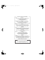
CONTENTS
[1]
INTRODUCTION . . . . . . . . . . . . . . . . . . . . . . . . . . . . . . . . . . . . 1 - 1
[2]
EXTERNAL VIEWS AND INTERNAL STRUCTURES . . . . . . . 2 - 1
[3]
UNPACKING AND INSTALLATION . . . . . . . . . . . . . . . . . . . . . . 3 - 1
[4]
OPERATIONAL DESCRIPTION . . . . . . . . . . . . . . . . . . . . . . . . 4 - 1
[5]
DISASSEMBLY AND ASSEMBLY . . . . . . . . . . . . . . . . . . . . . . . 5 - 1
[6]
MAINTENANCE . . . . . . . . . . . . . . . . . . . . . . . . . . . . . . . . . . . . 6 - 1
[7]
MACHINE OPERATION . . . . . . . . . . . . . . . . . . . . . . . . . . . . . . 7 - 1
[8]
ADJUSTMENTS . . . . . . . . . . . . . . . . . . . . . . . . . . . . . . . . . . . . 8 - 1
[9]
TROUBLESHOOTING . . . . . . . . . . . . . . . . . . . . . . . . . . . . . . . 9 - 1
[10] SIMULATIONS. . . . . . . . . . . . . . . . . . . . . . . . . . . . . . . . . . . . . 10 - 1
[11] ELECTRICAL SECTION . . . . . . . . . . . . . . . . . . . . . . . . . . . . . 11 - 1
Parts marked with “ “ are important for maintaining the safety of the set.
Be sure to replace these parts with specified ones for maintaining the safety and performance of the set.
SHARP CORPORATION
This document has been published to be used for
after sales service only.
The contents are subject to change without notice.
[co]CONTENTS.fm
1 ページ 2004年4月19日 月曜日 午後1時43分
CONTENTS
[1] INTRODUCTION
[6] MAINTENANCE
1. Product outline . . . . . . . . . . . . . . . . . . . . . . . . . . . . . . . 1-1
1. Maintenance System Table . . . . . . . . . . . . . . . . . . . . . . 6-1
2. Configuration . . . . . . . . . . . . . . . . . . . . . . . . . . . . . . . . 1-1
2. Discarding punch waste
(when a punch unit is installed) . . 6-1
3. Specifications . . . . . . . . . . . . . . . . . . . . . . . . . . . . . . . . 1-1
4. Consumable parts . . . . . . . . . . . . . . . . . . . . . . . . . . . . 1-1
[2] EXTERNAL VIEWS AND INTERNAL STRUCTURES
[7] MACHINE OPERATION
1. Staple sort mode. . . . . . . . . . . . . . . . . . . . . . . . . . . . . . 7-1
1. External view . . . . . . . . . . . . . . . . . . . . . . . . . . . . . . . . 2-1
2. Setup by the printer driver. . . . . . . . . . . . . . . . . . . . . . . 7-2
2. Internal structure . . . . . . . . . . . . . . . . . . . . . . . . . . . . . 2-1
3. Using the saddle stitch finisher functions
in copy mode . . 7-2
3. Finisher and saddle section . . . . . . . . . . . . . . . . . . . . . 2-2
4. Interface transport section . . . . . . . . . . . . . . . . . . . . . . 2-3
5. Puncher section (AR-PN1) . . . . . . . . . . . . . . . . . . . . . . 2-3
[3] UNPACKING AND INSTALLATION
1. AR-F14 . . . . . . . . . . . . . . . . . . . . . . . . . . . . . . . . . . . . . 3-1
2. AR-PN1 . . . . . . . . . . . . . . . . . . . . . . . . . . . . . . . . . . . . 3-7
[4] OPERATIONAL DESCRIPTION
1. Basic Operations . . . . . . . . . . . . . . . . . . . . . . . . . . . . . 4-1
2. Feed/Drive System . . . . . . . . . . . . . . . . . . . . . . . . . . . . 4-4
[8] ADJUSTMENTS
1. Finisher/saddle unit . . . . . . . . . . . . . . . . . . . . . . . . . . . . 8-1
2. Puncher unit (option). . . . . . . . . . . . . . . . . . . . . . . . . . . 8-1
[9] TROUBLE SHOOTING
1. Outline. . . . . . . . . . . . . . . . . . . . . . . . . . . . . . . . . . . . . . 9-1
2. Trouble code . . . . . . . . . . . . . . . . . . . . . . . . . . . . . . . . . 9-1
3. Troubleshooting . . . . . . . . . . . . . . . . . . . . . . . . . . . . . . . 9-2
[10] SIMULATIONS
3. Stapling Operation . . . . . . . . . . . . . . . . . . . . . . . . . . . . 4-7
1. Finisher/Saddle unit . . . . . . . . . . . . . . . . . . . . . . . . . . . 10-1
4. Delivery Tray Operation . . . . . . . . . . . . . . . . . . . . . . . . 4-10
2. Puncher unit (option). . . . . . . . . . . . . . . . . . . . . . . . . . . 10-1
5. Saddle Unit. . . . . . . . . . . . . . . . . . . . . . . . . . . . . . . . . . 4-11
6. Puncher Unit (option) . . . . . . . . . . . . . . . . . . . . . . . . . . 4-14
7. Detecting Jams. . . . . . . . . . . . . . . . . . . . . . . . . . . . . . . 4-16
8. Power Supply System. . . . . . . . . . . . . . . . . . . . . . . . . . 4-18
[5] DISASSEMBLY AND ASSEMBLY
1. Finisher Saddle Unit . . . . . . . . . . . . . . . . . . . . . . . . . . . 5-1
2. puncher Unit (option) . . . . . . . . . . . . . . . . . . . . . . . . . . 5-17
[11] ELECTRICAL SECTION
1. LEDs and Check Pins by PCB . . . . . . . . . . . . . . . . . . . 11-1
2. Wiring diagram (AR-F14) . . . . . . . . . . . . . . . . . . . . . . . 11-2
3. Wiring diagram (AR-PN1) . . . . . . . . . . . . . . . . . . . . . . . 11-4
[01]INTRODUCTION.fm 1 ページ
2004年4月28日 水曜日 午後4時59分
[1] INTRODUCTION
1. Product outline
This unit is installed to the following machines to perform the after-process of output paper from a copier, or a fax machine.
1) Employment of the through-type stapler
Employment of the through-type stapler allows to make saddle stitch by one stapler.
2) 3 kinds of auto staple functions
There are 3 staple positions available. (One position in the front, one position at the back, 2 positions at the center)
3) Saddle stitch function
Up to 10 sheets of paper can be stapled at the center and folded into two and discharged.
4) Punch function (Option)
By installation of a puncher unit, paper can be punched to make holes for a binder. (Applicable for 64 - 128g/m². OHP films cannot be used.)
Applicable models
AR-M237 / M277, AR-M236 / M276
2. Configuration
1. When installing this machine, the exclusive-use table (large) or the exclusive-use table (small) + the multi-stage paper feed unit
(AR-D21 or AR-D22) must be attached to in advance.
2. This unit cannot be installed with the following units:
•Finisher (AR-FN5N)
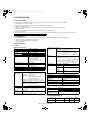
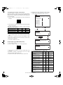
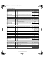
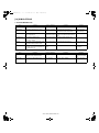
3. Specifications
A. AR-F14
(1) Basic specifications
Type
Transport speed
Transport reference
Tray type
Upper tray
(Number of trays) Lower tray
Paper exit direction
Paper exit paper size
Console type finisher
23/26/27 ppm
Center reference
Lift-up/down offset tray
Book tray for saddle stitch
Face down
A3, B4, A4, A4R, B5, B5R, A5,
11" x 17", 8.5" x 14", 8.5" x 13",
A5/Invoice R inhibited
A5/Invoice horizontal allowed
8.5" x 11", 8.5" x 11"R,
5.5" x 8.5"
Power consumption
60W or below
Power source
Supplied from the machine power
(DC24V, 2.5A)
External dimensions (W x D x H) 661 x 603 x 1016 (mm)
Occupying dimensions (W x D) 712 x 603 (mm)
Weight
About 38kg
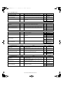
(2) Finishing section
Capacity of
paper exit and
load
Non-staple
*1,000 sheets (Small size)
500 sheets (Large size)
Staple sort
*30 sheets
* Equivalent to 64g/m² of paper
Max
1,000 sheets (Small size)
500 sheets: (Large size)
Less than 1,000 sheets and less than 30 copies
depending on the use environment and paper curl.
Large size
A3, B4,
11" x 17", 8.5" x 14", 8.5" x 13"
Small size
A4R, B5, B5R, A5,
8.5" x 11", 8.5" x 11"R, 5.5" x 8.5"R
Offset function
Provided
Paper size which A3, B4, A4, A4R, B5, B5R,
can be stapled
11" x 17", 8.5" x 14", 8.5" x 13", 8.5" x 11",
8.5" x 11"R
Kinds and
Normal paper 60 - 128g/m² (16 - 34lbs)
weights of paper Index paper
176g/m² (47lbs)
to be discharged Cover paper
200 g/m² (54lbs)
Quantity of paper 50 sheets
to be stapled
(Small size, 128g/m² x 2 + 80g/m² x 48)
(Max.)
25 sheets (Large size, 80g/m² x 25)
Large size
A3, B4,
11" x 17", 8.5" x 14", 8.5" x 13"
Small size
A4, A4R,
8.5" x 11", 8.5" x 11"R, B5, B5R
Stapling
3 kinds
(One in the front, one at the back: two positions)
two positions A3, B4, 11" x 17", 8.5" x 14",
8.5" x 13", A4, 8.5" x 11", B5, B5R
one at the back A3, B4, A4, A4R, B5, B5R
one in the front 11" x 17", 8.5" x 14", 8.5" x 13",
8.5" x 11", 8.5" x 11"R, B5, B5R
Staple supply
Staple cartridge replacement
Staple detection Staple empty Provided
detection
Cartridge
Provided
empty
detection
Staple jam
Provided
detection
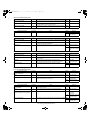
(3) Saddle stitch section
Stapling type
Stapling position
Weight of paper applicable for
saddle stitch
Paper size
Center stapling: Center folding
120mm pitch from the paper center
A3, A4R, B4,
11" x 17", 8.5" x 11"R
64 - 80g/m²
(Cover: 64 - 128g/m²)
Book tray stacking type
Fixed
Quantity of paper to be stapled 10 sets (6 - 10 pages)
20 sets (1 - 5 pages)(80g/m²)
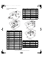
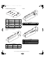
B. AR-PN1
Type
No. of punch holes
Size of paper
applicable for punching
Punch unit
AR-PN1A AR-PN1B AR-PN1C AR-PN1D
2 holes
2 / 3holes
4 holes
4 holes
Max. A3, Min. B5R
4. Consumable parts
Name
Content
Life
Staple cartridge Staple cartridge x 3 5000 x 3
AR-F14/PN1 INTRODUCTION 1-1
Product
name
AR-SC2
Remark
[02]EXTERNALVIEWS.fm 1 ページ
2004年4月19日 月曜日 午後1時36分
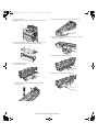
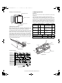
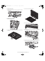
[2] EXTERNAL VIEWS AND INTERNAL STRUCTURES
1. External view
[1]
[2]
[3]
[4]
[5]
[6]
B. Saddle section
Stapler compiler
Top cover
Stapler section
Front cover
Saddle stitch tray
Offset tray
[1]
[1]
[2]
[3]
[4]
[5]
[6]
A. Finisher section
[3]
[2]
[3]
[4]
[5]
Fig. F01-301-02
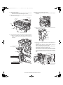
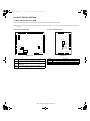
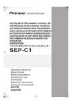
2. Internal structure
[1]
[2]
[4]
[5]
[6]
[7]
Book making stopper
Book making tray
Bundle transport roller
Book making exit roller
Paper folding roller
Paper pushing plate
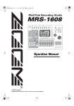
C. Puncher section (Option)
[1]
[2]
[3]
[4]
Fig. F01-301-03
[1]
[2]
[3]
[4]
Dice
Cam
Punch
Punch dust box
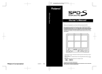
D. Interface transport section
[1]
[8]
[9]
[10]
[2]
[11]
Fig. F01-301-01
[1]
[2]
[3]
[4]
[5]
[6]
[7]
[8]
[9]
[10]
[11]
Paper exit tray
Alignment plate (Front, back)
Paddle
Paper exit roller
Process tray stopper
Transport roller
Puncher section (Option)
Paper exit belt
Bundle exit roller
Stapler
Saddle section
Fig. F01-301-04
[1]
[2]
Interface transport medium roller
Interface transport drive roller
AR-F14/PN1 EXTERNAL VIEWS AND INTERNAL STRUCTURES 2-1
[6]
[02]EXTERNALVIEWS.fm 2 ページ
2004年4月19日 月曜日 午後1時36分
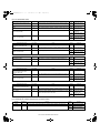
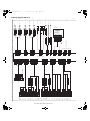
3. Finisher and saddle section
Code
A. Sensor
SSS
FE
Name
Active condition
LE
Lift lock sensor
SHPS
Slide home position
sensor
Stapler stapling HP : "L"
SPS
Self prime sensor
Cartridge staple
detected : "L"
SS
Staple sensor
Stapler cartridge
detected : "L"
FJHPS
FDSW
LE
TCS
FDS
JS
FES
STHPS
SPS
SS
Stapler HP : "H"
STHPS Stapler home position
sensor
LLLS
FDS
Front door sensor
Front cover open : "H"
TCS
Upper cover sensor
Upper cover open : "H"
FDSW
Front door switch
Front door closed : "H"
JS
Joint switch
Printer connected : "H"
SSS
Stapler safety switch
Oscillation guide closed :
"H"
SHPS
Remark
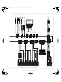
B. Motor and PWB
RJHPS
ULS
ARHPS
PHPS
OBHPS
O
FRHPS
FPM
ES
FFM
FFC
SLS
BES
FSM
AS
FPS
FHPS
Fig. F05-201-01
Code
Name
Active condition
ES
Entry sensor
Paper detected : "H"
PHPS
Paddle home position
sensor
Paddle HP : "H"
ARHPS Bundle roller home
position sensor
FJHPS
Remark
FAM
FRJM
FFJM
Oscillation guide
HP : "H"
[1]
Alignment home position Alignment tray (F)
sensor (front)
HP : "H"
RJHPS Alignment home position Alignment tray (R)
sensor (rear)
HP : "H"
AS
Alignment tray sensor
FLM
Paper detected : "H"
OBHPS Exit belt home position
sensor
Paper exit belt HP : "H"
BES
Tray paper sensor
Tray paper detected :
"H"
SLS
Paper level sensor
Paper detected : "H"
FPS
Bookbinding position
sensor
Paper detected : "L"
FHPS
Bookbinding home
position sensor
Folding operation
HP : "L"
FRHPS Bookbinding roller HP
sensor
Bundle transport roller
HP : "H"
FES
Paper detected : "H"
Bookbinding paper
sensor
FFSM
FE
Bookbinding clock
sensor
ULS
Lift upper sensor
Tray upper limit detected
: "H"
LLLS
Lift lower sensor
Tray lower limit detected
: "H"
Fig. F05-201-02
Code
Name
Active condition
FFM
Transport motor
Paper transport
FPM
Paddle motor
Oscillation guide drive,
paper exit to offset tray
FAM
Bundle exit motor
Paper exit operation
FFJM
Alignment motor
(front)
Alignment plate (F) drive
FRJM
Alignment motor (rear) Alignment plate (R) drive
FLM
Shift motor
Paper exit tray up/down
FFSM
Stapler/Fold motor
Stapling/paper folding
FSM
Slide motor
Staple unit sliding
AR-F14/PN1 EXTERNAL VIEWS AND INTERNAL STRUCTURES 2-2
Remark
[02]EXTERNALVIEWS.fm 3 ページ
2004年4月19日 月曜日 午後1時36分
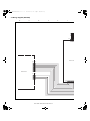
4. Interface transport section
B. Motor
FPNM
FJOS
FJM
FJES
FPSM
FJCS
A. Sensor
Code /
Brevity Code
Name
Active condition
Remark
FJOS
Interface transport unit
paper exit sensor
Paper detection: [L]
FJES
Interface transport unit
paper entry sensor
Paper detection: [L]
FJCS
Interface transport unit
cover sensor
Cover open: [L]
Fig. F05-202-02
Code
B. Motor
Active condition
Remark
Punch drive
FPSM Punch side motor
Punch slide unit transverse move
C. PWB
Code /
Brevity Code
FJM
Name
FPNM Punch motor
Name
Active condition
Remark
Interface transport motor Paper transport
[1]
5. Puncher section (AR-PN1)
A. Sensor
[4]
[2]
PE
[3]
Punch Home Position
PSHPS
[5]
Fig. F05-202-03
Code
Fig. F05-202-01
Code
Name
Active condition
Punch home position Punch HP
sensor
detected:"L"
PSHPS Punch side home
position
PE
Punch dust sensor
Name
[1]
Punch driver PWB
[2]
Side resist photo sensor PWB
[3]
Side resist LED PWB
[4]
Dust full photo sensor PWB
[5]
Dust full LED PWB
Remark
In the punch unit
Punch slide unit HP In the punch unit
detected:"H"
In the punch unit
AR-F14/PN1 EXTERNAL VIEWS AND INTERNAL STRUCTURES 2-3
[03]UNPACKINGANDINSTALLATION.fm
1 ページ 2004年4月27日 火曜日 午後7時4分
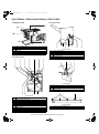
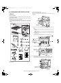
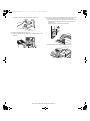
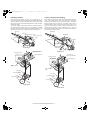
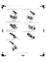
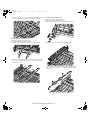
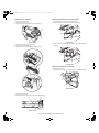
[3] UNPACKING AND INSTALLATION
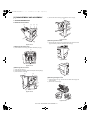
1.AR-F14
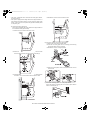
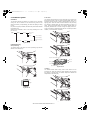
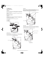
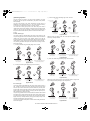
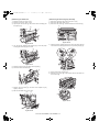
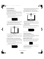
1) Remove the exit tray cover.
•If the copier is equipped with an exit tray cover:
Remove the screw and then remove the exit tray cover as shown in the
illustration.
<Before installation>
•For installation of AR-F14, an optional stand (small stand or large stand)
must have been installed.
•When adjusting the height of the finisher, be sure to perform step15)
with the finisher placed on the packing box.
•For improvement of workabillity, part of the description in this manual
may be modified without prior notice. In this case, refer to the service
manual.
2) Remove the internal cabinet and the paper holder arm from the
copier.
<1>Pull the lock lever to the left and pull out the rail dummy cover to
the front.
(If the second exit tray is provided, remove it together with the rail
dummy cover.)
<2>Unlatch the pawls of the exit dummy cover and remove the exit
dummy cover.
<3>Remove the paper holder arm from the exit dummy cover.
<4>Remove the screw and then remove the rear exit cover.
Saddle finisher
instruction manual:
1 copy
Stapling position label:
2 sheets
3) Remove the rear cabinet.
<1>Remove the screw and then remove the maintenance cover.
<2>Remove the four screws and then remove the rear cabinet.
Punch position label:
2 sheets
Turn off the main switch of the copier and then remove the power plug
from the outlet.
AR-F14/PN1 UNPACKING AND INSTALLATION 3-1
[03]UNPACKINGANDINSTALLATION.fm
2 ページ 2004年4月27日 火曜日 午後7時4分
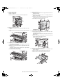
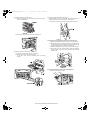
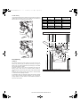
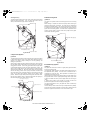
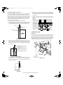
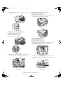
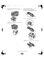
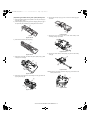
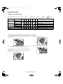
4) Remove the right cabinet.
<1>Open the bypass tray.
<2>Open the right door.
<3>Remove the two screws and then remove the right cabinet.
5) Remove the copier second exit unit.
<1>Remove the connector of the copier second exit unit from the
copier.
<2>Remove the four screws and then remove the copier second exit
unit.
6) Attach the supplied F14 second exit unit.
<1>Arrange the connector harness of the supplied F14 second exit
unit as shown in the illustration.
<2>Attach the F14 second exit unit to the copier and secure it with
the four screws.
At this time, take care so that the harness is not caught between
the copier and the second exit unit.
<3>Connect the connector to the copier.
7) Attach the rear cabinet.
<1>Reattach the rear cabinet to its original position and secure it
with the four screws.
<2>Reattach the maintenance cover to its original position and
secure it with the screw.
<3>Reattach the right cabinet that has been removed in step4) to its
original position and secure it with the two screws.
<4>Close the right door and the bypass tray.
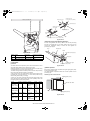
8) Attach the docking mounting angles.
<1>Cut out the two cut-out portions on the left cabinet of the copier
using nippers or the like.
(Be careful about the orientation of the nippers so that the cross
section is flat.)
<2>Secure the docking mounting angle F and docking mounting
angle R with two screws A (M4 x 10) each.
(F/R is indicated with marking.)
9) Remove the covers from the docking unit.
<1>Remove the screw and slide the top cover in the direction of the
arrow to remove it.
<2>Remove the two screws and then remove the front cover.
<3>Remove the four screws and then remove the left cover.
AR-F14/PN1 UNPACKING AND INSTALLATION 3-2
[03]UNPACKINGANDINSTALLATION.fm
3 ページ 2004年4月27日 火曜日 午後7時4分
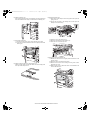
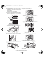
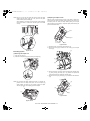
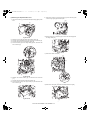
10) Attach the docking unit.
Insert docking mounting angel F and docking mounting angel R that
have been attached to the copier, into the holes of the docking unit.
11) Secure the docking unit.
<1>Use two screws A (M4 x 10) to secure the unit to the copier.
<2>Then use the screw that has been remove in step2) to secure the
docking unit.
12) Attach the paper holder arm to the transport unit.
Attach the paper holder arm that has been removed in step2) to the
lower part of the transport unit.
13) Attach the transport unit.
<1>Place the rail of the transport unit on the guide of the copier and
gently push it in.
<2>Connect the connector of the docking unit and then push the
transport unit in until it stops.
<3>Open the cover of the transport unit.
<4>Secure the unit with two screws A (M4 x 10).
<5>Close the cover of the transport unit.
14) Attach the covers of the docking unit.
<1>Reattach the left cover to its original position and secure it with
the four screws.
<2>Secure the front cover with the two screws.
<3>Secure the front cover to the docking unit using screw C from
above the front cover.
<4>Slide the upper cover to attach as shown in the illustration and
secure it with the screw.
AR-F14/PN1 UNPACKING AND INSTALLATION 3-3
[03]UNPACKINGANDINSTALLATION.fm
4 ページ 2004年4月27日 火曜日 午後7時4分
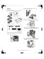
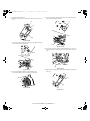
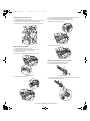
•If the copier is equipped with a small stand and three paper drawers,
proceed to step16).
•If the copier is equipped with a large stand and two paper drawers or a
small stand and four paper drawers, you must change the height of the
finisher. In this case, be sure to perform step15) with the finisher placed
on the packing box.
<4>Reattach the cover and secure it with the screw.
15) Change the height of the finisher
(if the copier is equipped with a large stand and two paper drawers or
a small stand and four paper drawers)
<1>Remove the screw and then remove the cover.
16) Connect the finisher to the stand / paper drawers.
<1>Remove the cover from the finisher stand.
<2>Insert the connecting plate into the connecting plate mounting
section and attach it with two screws B.
<3>Reattach the cover to its original position.
<2>Remove the four screws that secure the fittings of the front side
and rear side respectively and then remove the two fittings.
<4>Attach the ground plate as shown in the illustration and secure it
with screw B.
<3>Extend the finisher stand, reattach the two fittings that have been
removed in <2>, and secure them with four screws for each.
17) Secure the connecting plate to the stand / paper drawers.
Secure the finisher connecting plate to the stand / paper drawers
with two screws B (M4 x 6).
AR-F14/PN1 UNPACKING AND INSTALLATION 3-4
[03]UNPACKINGANDINSTALLATION.fm
5 ページ 2004年4月27日 火曜日 午後7時4分
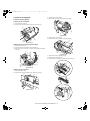
18) Install the stapler unit into the finisher.
<1>Remove the packing the tape (two pieces) from the locations
shown in the illustration.
20) Check and adjust the height of the finisher.
Bring the finisher close to the copier and check that the guide pin is
inserted smoothly into the connecting hole of the finisher.
If the guide pin should not be inserted smoothly, adjust as follows.
<2>Open the finisher front cover and insert the stapler unit.
Guide pin
a. If the guide pin is deviated from the finisher connecting hole:
<1>Loosen the adjustment section securing screw on the rear side.
<2>Remove the cap with a flat-blade screwdriver or the like and use
the height adjusting screw to adjust the position so that the guide
pin matches the center of the finisher connecting hole.
<3>Loosen the adjustment section securing screw on the front side.
<4>If the guide pin can be inserted smoothly, tighten the adjusting
section securing screws on the front side and the rear side and
attach the cap.
19) Attach the exit tray to the finisher.
<1>Hang the two pawls of the exit tray on the finisher.
<2>Use the four screws D to secure the exit tray.
At this time, check that the positioning dowel is securely
inserted.
b. If the guide pin matches the finisher connecting hole:
<1>Push the finisher into the copier.
AR-F14/PN1 UNPACKING AND INSTALLATION 3-5
[03]UNPACKINGANDINSTALLATION.fm
6 ページ 2004年4月27日 火曜日 午後7時4分
<2>If the gap between the copier and the finisher is not uniform at
the upper and lower parts, remove the caps from the front side
and the rear side of the finisher stand with a flat-blade
screwdriver or the like.
Then, remove the screws of the front and rear subcovers (one
screw for each) and then remove the subcovers.
<3>Loosen the four adjustment section securing screws located at
the positions shown in the illustration and then rotate the front
and rear height adjusting screws so that the gap becomes
uniform.
Gap
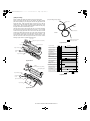
22) Set the staple cartridge in the stapler unit.
<1>Open the finisher front cover and pull out the stapler unit.
<2>Turn the roller rotating knob unit the triangle mark is aligned with
the index.
<3>Insert the staple cartridge securely into the staple section unit it
clicks.
Gap
<4>If the gap becomes uniform, tighten the adjustment section
securing screws and reattach the caps and the subcovers.
21) Connect the connector of the finisher.
Connect the connector of the finisher to the connector of the docking
unit.
Note: Check also that the right and left parts of the staple
cartridge do not float.
<4>Insert the staple section and close the finisher front cover.
23) Paste the stapling position label.
Paste the stapling position label to the document feeder.
Connect the connector of the finisher to the connector of the copier
and then tighten the screws.
Staple position label
Insert the power plug of the copier to the outlet and turn on the main
switch of the copier.
AR-F14/PN1 UNPACKING AND INSTALLATION 3-6
[03]UNPACKINGANDINSTALLATION.fm
7 ページ 2004年4月27日 火曜日 午後7時4分
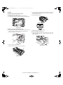
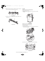
2. AR-PN1
<1> Then remove the power plug of the main unit from the outlet.
<2> Remove the connector of the finisher.
<Before installation>
For installation of AR-PN1A/PN1B/PN1C/PN1D, a saddle stitch finisher
(AR-F14) must have been installed.
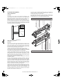
2) Remove the front cabinet and the rear cabinet from the finisher.
<1> Open the front door of the finisher and remove the jam handling dial.
Parts included
Jam handling dial
Harness A (purple): 1 pc.
Screw
(M4 x 6 with rosette)
: 1 pc.
Harness B (orange): 1 pc.
<2> Remove the two front cabinet securing screws, pull out the staple
unit until it stops, then remove the pawl of the front cabinet in the
direction indicated by the arrow and remove the front cabinet..
Dust box label:
1 sheet
Hole punch position label*:
2 sheets
Pawl
* Will not be used.
Use the hole punch
position labels packed
in AR-F14
Staple unit
1) Turn off the main switch of the main unit.
Screws
Front cabinet
OFF
<3> Remove the three rear cabinet securing screws, remove the pawl in
the direction indicated by the arrow, and remove the rear cabinet.
At this time, remove the relay harness through the opening of the
rear cabinet.
Pawl
Rear
cabinet
Screw
Screw
Opening for
relay harness
Relay harness
AR-F14/PN1 UNPACKING AND INSTALLATION 3-7
[03]UNPACKINGANDINSTALLATION.fm
8 ページ
2004年4月27日 火曜日 午後7時4分
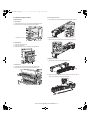
3) Remove the top cover.
<1> Remove the four top cover securing screws and remove the top
cover.
<3> Remove the boss on the upper side of the paper entry PG.
Screw
Top cover
<4> Remove the boss on the lower side of the paper entry PG with a
straight-slot screwdriver.
<2> Remove the four pawls from the top cover and separate the cover
into the upper and lower portions. Reuse the upper portion.
Pawl
Top cover
Pawl
<5> Remove the beak PG (paper entry PG).
4) Remove the paper entry PG.
<1> Remove the dust box.
1
<6> Replace the dust box to the original position.
<2> Remove the screws (2 pcs.) which are fixing the beak PG
(paper entry PG).
AR-F14/PN1 UNPACKING AND INSTALLATION 3-8
[03]UNPACKINGANDINSTALLATION.fm
9 ページ
2004年4月27日 火曜日 午後7時4分
5) Attach the punch module.
<1>Insert the two bosses of the punch unit into the boss holes of the
finisher and fix the punch module using three screws.
Note: For the screws, use a supplied screw and the two screws that have
been removed in step 4).
7) Reattach the covers that have been removed.
<1>Hang the two pawls of the top cover and secure them using the
two screws.
Screw
Top cover
Screw
Boss hole
Boss
Boss hole
Boss
Screw
Pawl
<2>Pass the relay harness to the rear cabinet and secure the rear
cabinet using the three screws.
Punch module
Screw
Rear cabinet
Screw (with rosette)
(supplied with this unit)
Screw
6) Connect the harness of the punch module to the PWB of the finisher.
<1>Remove the clamps that fix the harness, handle the wiring of
harness A (purple) and harness B (orange), and fix them with
the clamps.
Opening for
relay harness
Relay harness
Screws
Harness B (orange)
Harness A (purple)
Clamps
<3>Remove the lock release lever that has been attached to the
front cabinet.
Reattach the front cabinet to its original position, push in the
staple unit, and attach it using the two screws.
Insert the protrusion (B) of the lock release lever that has been
removed before to the hole (C) of the latch arm.
After attaching it, move the lever to check that it moves smoothly.
If the lever does not move smoothly, remove the lock release
lever by releasing the pawl at the lower part of the lock release
lever using a flat-blade screwdriver or the like and then insert it
again.
Pawl (D)
Latch arm
Staple unit
Harness B (orange)
Connect to CN14 on PWB
Clamps
(C)
Harness A (purple)
Connect to CN12 on PWB
Lock release lever (A)
Screws
Front cabinet
AR-F14/PN1 UNPACKING AND INSTALLATION 3-9
Projection (B)
[03]UNPACKINGANDINSTALLATION.fm
10 ページ 2004年4月27日 火曜日 午後7時15分
<4>Reattach the jam handling dial and close the front cover.
9) Connect the connector to the stand/paper drawer and connect the
AC cord of the power supply unit to the main unit of the printer.
<1>Connect the connector of the relay harness of the finisher to the
stand/paper drawer and tighten the screws of the connector.10)
Paste the label.
(Paste it only if the scanner module is installed.)
Jam handling dial
8) Paste the dust box label to the top cover.
<1> Paste the supplied dust box label to the location indicated in the
illustration.
<1>Paste the label to the position shown in the illustration.
Staple position label
Punch position label
AR-F14/PN1 UNPACKING AND INSTALLATION 3-10
[04]OPERATIONALDESCRIPTION.fm 1 ページ
2004年4月19日 月曜日 午後1時37分
[4] OPERATIONAL DESCRIPTION
1. Basic Operations
A. Specifications
The finisher serves to deliver sheets coming from its host machine. The
mode of delivery may be non-sort stack, job offset*, or staple delivery.
The saddle unit built into the finisher is used to fold a stack of sheets
coming from the finisher unit in half for delivery.
All these operations are controlled by various commands sent by the
host machine in addition to the commands from the finisher controller
PCB.
The puncher unit (option) is designed for installation to the pickup
assembly of the finisher, and is used to punch holes in sheets coming
from the host machine.
The above operations are controlled with various commands from the
finisher controller PCB as well as the commands from the punch
controller PCB.
Control system
Puncher unit drive
system (puncher unit;
option)
Alignment drive system
Stapler drive system
Delivery drive system
Feed drive system
Tray drive system
Saddle unit
drive system
B. Outline of the Electrical Circuitry
The sequence of finisher operations is controlled by the finisher
controller PCB. The finisher controller PCB is a 16-bit microprocessor
(CPU), and is also used for combination with the host machine (serial).
The finisher controller PCB drive motors and other loads in response to
the various commands from the host machine. It also communicates
such data as on the states of various sensors and switches to the host
machine by way of the serial communication line.
The ICs mounted to the finisher controller PCB have the following
functions:
•IC13 (CPU)
Controls sequence of operations.
•IC12 (EEP-ROM)
Backs up adjustment settings.
•IC6 (EP-ROM)
Stores sequence programs.
•IC11 (communication IC)
Communicates with the host machine.
•IC1 (regulator IC)
Generates 5 V.
F02-102-01 shows the flow of signals between finisher and options
controller:
Finisher unit
Finisher
controller
PCB
IC13
CPU
Host machine DC
controller PCB
CPU
Motor
Clutch
IC12
EEP-ROM
Switch
IC11
Communication IC
Sensor
IC6
EP-ROM
Puncher unit (option)
Sensor
Punch controller
PCB
IC1
Regulator IC
Motor
Fig.F02-102-01
Fig.F02-101-01
NOTE:The position of delivery is shifted to the front/rear for each stack to
assist sorting.
AR-F14/PN1 OPERATIONAL DESCRIPTION 4-1
[04]OPERATIONALDESCRIPTION.fm 2 ページ
2004年4月19日 月曜日 午後1時37分
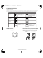
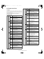
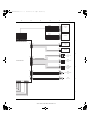
C. Inputs to and Outputs from the Finisher Controller PCB
•Outputs from the Finisher Controller PCB (1/2)
Finisher controller PCB
•Inputs to the Finisher Controller PCB (1/2)
Finisher controller PCB
CN44-3
-1
-2
Inlet sensor
CN43-1
-3
-2
+24 V
Binding clutch
-1
CN42-3 CN16-10 +5 V
-1
-12 ENT_S
-11
-2
When the sensor
detects paper, ‘1’ .
-2
CN18-1
-1
-2
-1
CN10-1
-5
-2
-2
-4
-3
-3
-4
-4
-2
-5
-5
-1
-6
-6
-6
-1
CN10-7
-5
-2
-8
-4
-3
-9
-4
-10
-2
-5
-11
-1
-6
-12
-6
-1
CN13-1
-5
-2
-2
-4
-3
-3
-4
-4
-2
-5
-5
-1
-6
-6
FFC
-2
Feed motor
-6
CN72
ES
When the drive is transmitted,
‘1’.
B_CLU
FFM
CN54-1
-3
-2
CN53-3
-1
-2
RJHPS
Aligning plate
home position
sensor (rear)
-3
CN9-7
+5 V
When the swing guide
-9
BDL_ROL_HP is at home position, ‘1’.
-8
FJHPS CN23-3
Aligning plate
home position
sensor (front)
When the paddle is at
home position, ‘1’.
-1
-2
CN4 +5 V
-3 F JOG_HP
-2
CN36-3
-1
-2
CN5-13 +5 V
-15 R JOG_HP
-14
FEEDMTR_A
FEEDMTR_*A
FEEDMTR_B
Switches between ‘1’ and
‘0’ according to the
direction of motor rotation.
FEEDMTR_*B
+24 V
When the aligning
plate (front) is at
home position, ‘1’.
Paddle motor
FPM
CN57
ARHPSCN55-3
-1
-2
Swing guide
home position
sensor
CN9-1 +5 V
-3 PDL_HP
-2
CN56
+24 V
PHPS CN51-1
-3
-2
Paddle home
position sensor
-3
When the aligning
plate (rear) is at
home position, ‘1’.
PDLMTR_A
PDLMTR_*A
PDLMTR_B
Switches between ‘1’ and
‘0’ according to the
direction of motor rotation.
PDLMTR_*B
Delivery belt
home position
sensor
Tray paper sensor
CN30-3
-1
-2
CN29-1
-3
-2
CN28-9
-7
-8
CN5-1
+5 V
When the sensor
-3
ADJ_TRAY_S
detects paper, ‘1’.
-2
Delivery motor
FAM
OBHPS
CN31-3
-1
-2
-4
-6
-5
-6
-4
-5
-4
+5 V
When the delivery belt
-6
EJCT_BLT_HP
is at home position, ‘1’.
-5
BES CN32-3
-1
-2
-7
-9
-8
-3
-1
-2
-7 +5 V
-9 TRY_EMPS
-8
Alignment motor
(front)
-3
Paper surface
sensor
CN34-1
-3
-2
CN33-3
-1
-2
CN5-10 +5 V
-12 LVL_S
-11
CN62-5
CN3-1
-2
-4
-2
-3
-3
-3
-4
-2
-4
-5
-1
-5
CN65-1
CN64-5
CN3-6
-2
-4
-7
-3
-3
-8
-4
-2
-9
-5
-1
-10
When paper is present
on the tray, ‘1’.
When the paper
surface is detected,
‘1’.
Alignment motor
(rear)
Folding position
sensor
FPS CN39-3
-2
-1
CN38-1
-2
-3
CN16-1
+5 V
-2
BIND_P
-3
BIND_L
CN37-9
-8
-7
When paper is
detected, ‘0’.
When LED is lit, ‘1’.
EJCTMTR_A
EJCTMTR_*A
EJCTMTR_B
Switches between ‘1’ and
‘0’ according to the
direction of motor rotation.
EJCTMTR_*B
+24 V
CN63-1
FFJM
SLS CN35-3
-1
-2
CN59
+24 V
AS
Processing
tray sensor
FJOGMTR_A
FJOGMTR_*A
FJOGMTR_B
Switches between ‘1’ and
‘0’ according to the
direction of motor rotation.
FJOGMTR_*B
+24 V
FRJM
Fig.F02-103-01
RJOGMTR_A
RJOGMTR_*A
RJOGMTR_B
Switches between ‘1’ and
‘0’ according to the
direction of motor rotation.
RJOGMTR_*B
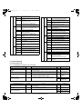
•Inputs to the Finisher Controller PCB (2/2)
Fig.F02-103-03
Finisher controller PCB
Folding home
position sensor
FHPS
CN40-3 CN38-4
-6
-1
-5
-2
CN37-6 CN16-4 +5 V
-4
-6 BIND_HP
-5
-5
•Outputs from the Finisher Controller PCB (2/2)
When at folding home position, ‘0’.
Finisher controller PCB
-3
-1
-2
-7 +5 V
-9 BIND_ROL_HP When the stack feed roller
(upper) is at home position, ‘1’.
-8
Shift motor
FE
Staple/fold motor
clock sensor
ULS
Shift upper limit
sensor
LLLS
Shift lower limit
sensor
LE
Shift motor clock
sensor
FDS
Front door sensor
TCS
Upper cover sensor
XXXX
Full stack sensor
JS
N. O.
CN47-3
-1
-2
CN15-1
+5 V
-3
BIND_EMPS
-2
CN52-1
-2
-3
CN9-6 +5 V
-5 BIND_CLK
-4
CN50-3
-1
-2
CN15-10 +5 V
-12 SIFT_UPLMT
-11
When the sensor
detects paper, ‘1’.
When the staple/fold motor is
rotating, alternates between
‘1’ and ‘0’.
CN15-7 +5 V
-9
SIFT_DNLMT
-8
CN48-3
-1
-2
CN15-4 +5 V
-6
SIFT_CLK
-5
CN25-3
-1
-2
CN4-7 +5 V
-9 FDOOR_S
-8
When the front door
is open, ‘1’.
CN24-3
-1
-2
CN4-4 +5 V
-6 TOPCOV_S
-5
When the upper cover
is open, ‘1’.
CN73-3
-1
-2
-1
-2
-2
-1
-1
-2
CN6-1
SIFTMTR_1
-1
-2 SIFTMTR_0
FFSM
-1
-2
CN6-3
BINDMTR_1
-1
-4 BINDMTR_0
When the tray is at the
lower limit, ‘1’.
While the shift motor
is rotating, alternates
between ‘1’ and ‘0’.
CN19-1 +5 V
-3 PAPER_F
-2
When the paper is
full, ‘1’.
+24 VP
CN69-2
CN8-6
-1
-5
CN68-2
CN8-4
-1
-3
SSS
N. O.
CN66-2
CN8-2
-1
-1
JOINT SW
When connected to
the host machine, ‘1’.
FRONT SW
When the front
door is closed, ‘1’.
Switches between ‘+’ and
‘–’ according to the
direction of motor rotation.
Staple/fold motor
-2
When the tray is at the
upper limit, ‘1’.
CN49-3
-1
-2
FDSW
N. O.
Front door switch
FLM
CN70
Bind tray sensor
Stapler safety
switch
-7
-9
-8
-2
FES
Joint switch
CN41-3
-1
-2
CN71
FRHPS
CN70
Stack feed roller
(upper) home
position sensor
STPLSAFE SW When the swing
guide is closed, ‘1’.
Fig.F02-103-02
AR-F14/PN1 OPERATIONAL DESCRIPTION 4-2
Fig.F02-103-04
Switches between ‘+’ and
‘–’ according to the
direction of motor rotation.
[04]OPERATIONALDESCRIPTION.fm 3 ページ
2004年4月19日 月曜日 午後1時37分
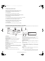
•Inputs to and Outputs from the Finisher Controller (1/2)
Stapler unit
Finisher controller PCB
Slide home
position sensor
+5 V
SHPS
•Inputs to and Outputs from the Punch Controller PCB
CN72-5
CN72A-5
Punch controller PCB
When the stapler is at home
position, ‘1’.
CN72A-5 CN11-3 SLID_HP
XXXX
J2008-3
-1
-2
Punch home
position sensor
Staple home
position sensor
+5 V
STHPS
CN72-4
Staple empty
sensor
SPS
D. Inputs to and Outputs from the Punch Controller
PCB(option)
CN72A-4
CN72A-4 CN11-4 STPL_HP
When the stapler is at
stapling home position, ‘0’.
PSHPS J2007-3
-1
-2
Horizontal
registration
home position
sensor
PE
+5 V
CN72-3
CN72A-3
CN72A-3 CN11-5 HOOK_S
When the cartridge has
staples, ‘0’.
When the hole puncher is
at home position, ‘0’.
J1006-1 +5 V
-3
SLIDE
-2
When the punch slide
unit is at home position,
‘1’.
J1006-7
+5 V
-9
CLOCK
-8
Waste full LED PCB
Staple top
position sensor
+5 V
SS
CN72A-2
CN72A-2 CN11-6
+5V
When the staple is at top
the stapler, ‘0’.
SELF_P
+5 V
CN72-6
CN72A-6
CN72A-6 CN11-2
CN72-1
CN72A-1
CN72A-1 CN11-7
CN72-7
CN72A-7
CN72A-7 CN11-1
-2
DUSTLED
When the light is
blocked, ‘0’.
Waste full photosensor PCB
PT131
STPL_CNCT
J1005-3
When the stapler is
connected, ‘0’.
DUSTPTR
4
Slide motor
FSM
CN72-10 CN72B-5
CN72B-5
CN72-11 CN72B-4
CN72B-4
CN7-3 SLIDMTR_A
CN7-4 SLIDMTR_*A
CN72-12 CN72B-3
CN72B-3
CN7-5
CN72-13 CN72B-2
CN72B-2
CN7-6 SLIDMTR_*B
Photosensor PCB
Switches between ‘1’ and
‘0’ according to the direction
of motor rotation.
SLIDMTR_B
PT1
PT3
PT4
CN2-1
-3
-4
-5
-7
-6
Host
machine
PT5
+24 V
GND
GND
TXD
RXD
+5 V
+5 V
PT2
J1007-12
-11
-10
-9
-8
-7
SREG1*
SREG2*
SREG3*
SREG4*
PAEND*
-13
Fig.F02-104-01
+24 V
•Outputs from the Punch Controller PCB
-2
Punch controller PCB
LED PCB
LED5
LED4
•Inputs to and Outputs from the Finisher Controller (2/2)
Interface
transport
paper exit
sensor
FJOS
LED3
LED2
Finisher control PWB
CNFJ1-17
-16
-3
-2
CNFJ1CN73C-1
-17
-2
-3
-16
+5V
J1007-6
Fig.F02-103-05
CNFJ2-1
LED1
-1
-5
-4
-3
-2
+5V
CN73A-8
"0" when paper is detected.
CN21-2
-7
LVL_E_S
-6
-3
When ‘1’, LED goes ON.
J1002-1
CNFJ3-1
CNFJ1-14
-13
CNFJ1CN73C-4
-14
-5
-6
-13
+5V
CN73A-5
"0" when paper is detected.
CN21-4
-5 LVL_P_S
-4
-3
-6
Interface
transport
cover sensor CNFJ4-3
FJCS
CNFJ1-2
-11
-10
-1
-2
J1001-1
-2
CNFJ1CN73C-7
-11
-8
-10 CN73D-2
FPSM
+5V
CN73A-2
CN21-7
-1
-8 LVL_C_S
CN73B-8 -9
-3
"0" when the interface
transport cover is open.
-4
Fig.F02-104-02
CNFJ5
-4
-3
-1
-2
-5
CNFJ1-2
-7
-6
-5
-4
-3
CNFJ1-2
CN73D-9
-7
-4
-5
-6
-5
-6
-7
-4
-8
-3
CN73B-6
-5
-4
-3
-2
CN19-2
-3
-4
-5
-6
+24V
A
*A
B
*B
Switches between ‘+’
and ‘–’ according to
the direction of motor
rotation.
FPNM
Horizontal
registration
motor
FJM
LEDON5
LEDON4
LEDON3
LEDON2
LEDON1
Punch motor
-3
-2
Interface
transport
motor
When paper is
detected, ‘0’.
Communication line
CN1-1
Interface
transport
paper entry
sensor
FJES
While the punch motor
is rotating, alternates
between ‘0’ and ‘1’.
J1005-1
LED121
CN72-2
+5 V
J2009-3
-1
-2
Punch motor
clock sensor
J1006-4
+5 V
-6
PUNCH
-5
The pulse signal is
switched depending
on the motor RPM.
+24V
AR-F14/PN1 OPERATIONAL DESCRIPTION 4-3
A
B
A*
B*
Switches the pulse
signals according to
the rotation of the motor.
[04]OPERATIONALDESCRIPTION.fm 4 ページ
2004年4月19日 月曜日 午後1時37分
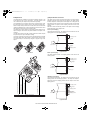
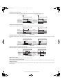
2. Feed/Drive System
b.Job Offset
A. Outline
The machine performs the following in response to the commands
coming from its host machine on the sheets arriving from the host
machine for delivery: simple stacking, job offset, and stapling or folding
(in two).
If a punch unit (option) is installed, the sheets are pouched and delivered
to the delivery tray.
Sheets may be delivered in either of five ways (including one for the
puncher unit):
Delivery
method
Normal
delivery
Punching
The machine pulls the sheet once to the processing tray. It then moves
the sheet to the front or the rear using the aligning plate. When it has
deposited a specific number of sheets, it delivers them in the form of a
aligning plane. When the number of sheets stacked on the processing
tray reaches a specified value, the sheets are delivered in a form of a
stack. Even if the specified value is not reached, stacked sheets are
temporarily delivered when 10 sheets of large-size paper (300 mm or
longer) or 30 sheets of small-size paper (299 mm or shorter) have been
stacked. (5- and STMT-sizes: 10 sheets)
Simple stacking
Job offset
Stapling
Front 1-point stapling
Rear 1-point stapling
Middle 2-point stapling
Saddle delivery
Stitching
Middle 2-point stapling
Fig.F02-201-01
(1)Normal Delivery
a.Simple Stacking
The machine pulls in the sheet once to the processing tray and then
delivers it to the delivery tray.
Results of offset delivery (4 jobs)
4th set
3rd set
2nd set
1st set
(direction of delivery)
Fig.F02-201-03
c.Stapling
The machine stacks sheets coming from its host machine on the
processing tray. When the number of sheets stacked on the processing
tray reaches a specified value, the finisher staples them delivers the
stapled stack to the delivery tray.
Tray
Paper
Fig.F02-201-02
Fig.F02-201-04
AR-F14/PN1 OPERATIONAL DESCRIPTION 4-4
[04]OPERATIONALDESCRIPTION.fm 5 ページ
2004年4月19日 月曜日 午後1時37分
d.Saddle Delivery
The machine deposits a stack of sheets on the processing tray, staples it
(middle 2-point), and then moves it to the saddle unit. The saddle unit
folds the stack in two, and delivers it to the bind tray.
Notation
Name
Description
Connector on finisher
controller PCB
FFM
Feed motor
Stepping motor
FPM
Paddle motor
Stepping motor
CN10
CN10
FAM
Delivery motor
Stepping motor
CN13
FFJM
Alignment plate
motor (front)
Stepping motor
CN3
FRJM
Alignment plate
motor (rear)
Stepping motor
CN3
FFSM
Staple/fold motor Brush DC motor CN6
Table.T02-202-01
FFJM
FRJM
Feed motor
drive signal FEEDMTR
Bind clutch drive signal B_CLU
Paddle motor
drive signal PDLMTR
Alignment plate motor
(front) drive signal FJOGMTR
Alignment plate motor
(rear) drive signal RJOGMTR
Finisher controller PCB (1/2)
FPM
FFM
FFC
FAM
FSM
FLM
PI14
Fig.F02-201-05
AR-F14/PN1 OPERATIONAL DESCRIPTION 4-5
Finisher controller PCB (2/2)
Fig.F02-202-01
Staple/fold motor clock detect signal
BIND_CLK
Staple/fold motor drive signal BINDMTR
The machine forwards the sheets coming from its host machine to the
delivery tray, processing tray, or saddle unit according to the type of
delivery used. The sheets forwarded to the processing tray or the saddle
unit are offset, stapled, or folded.
F02-202-01 shows the motors that are associated with moving and
aligning sheets. These motors are controlled (rotated clockwise or
counterclockwise) by the microprocessor (CPU) on the finisher controller
PCB.
The paper path is equipped with the sensors shown in T02-202-02 used
to monitor the arrival or passage of sheets.
If a sheet fails to arrive at or move past a specific sensor within a specific
period of time, the finisher controller will assume a jam, and stops the
ongoing operation and, at the same time, communicates the presence of
a jam to the host machine.
Slide motor drive signal SLIDMTR
(1)Outline
Shift motor drive signal SIFTMTR
B.Feed/Delivery
Delivery motor drive signal EJCTMTR
FFSM
[04]OPERATIONALDESCRIPTION.fm 6 ページ
2004年4月19日 月曜日 午後1時37分
Aligning plate (rear)
home position sensor (RJHPS)
Aligning plate (rear)
Inlet paper detect signal ENT_P
Fold position paper detect signal BIND_P
Finisher controller PCB
Light-shielding plate
Alignment plate (front)
motor (FFJM)
Alignment plate (rear)
motor (FRJM)
Aligning plate
(front)
ES
(Front)
Light-shielding plate
Paper
Aligning plate (front) home position sensor (FJHPS)
Fig.F02-203-01
FPS
(2)Processing Tray Paper Stacking Operation
A sheet coming between the delivery rollers is fed onto the processing
tray.Then, the paddle taps on the sheet surface twice (once for the
second and subsequent sheets) to locate the sheet against the
processing tray stopper.
Paper
Aligning plate
Paddle
Stack delivery roller (upper)
Fig.F02-202-02
Notation Name
Description
Connector on finisher
controller PCB
ES
Inlet sensor
Photointerrupter CN16
FPS
Fold position sensor Photointerrupter CN16
Swing guide
Table.T02-202-02
C.Job Offset
Processing tray stopper
Delivery belt
(1)Outline
Stack delivery roller (lower)
"Job offset" refers to the operation by which the machine delivers a set of
sheets with them pulled forward or backward for sorting.
Switching between the forward and backward directions is made using
an aligning plate (front) and an aligning plate (rear).
The sheet coming between the delivery rollers is fed onto the processing
tray and then fed toward the stopper by the paddle.
A swing guide is at the up position while a sheet is being pulled onto the
processing tray or during alignment. It is at the down position during
stack feeding, stack delivery, or stapling.
At power-on, the finisher controller PCB drives the aligning plate (front)
motor (FFJM) and the aligning plate (rear) motor (FRJM) to return the
two aligning plates to their home positions.
Sensor
Symbol Connector Function
Motor
Drives the
aligning plate
(front)
Aligning FFJM
plate
(front)
motor
Aligning plate RJHPS CN5-15
(rear) home
position sensor
Drives the
aligning plate
(rear)
Aligning FRJM
plate
(rear)
motor
Swing guide
home position
sensor
Drives the
swing guide
drive.
Paddle
motor
FPM
Drives the
Paddle
paddle
motor
(feeds paper).
FPM
Paddle home
PHPS
position sensor
CN9-3
Each sheet is pulled forward or backward using the aligning plate (front)
and the aligning plate (rear).
The offset operation is performed each time a sheet is pulled onto the
processing tray.
Offsetting in the forward direction
Aligning plate (rear)
Symbol
Aligning plate FJHPS CN4-3
(front) home
position sensor
ARHPS CN9-9
Fig.F02-203-02
(3)Offset Operation
Sheet to be offset
Tray
Aligning plate (front)
Fig.F02-203-03
Table.T02-203-01
AR-F14/PN1 OPERATIONAL DESCRIPTION 4-6
[04]OPERATIONALDESCRIPTION.fm 7 ページ
2004年4月19日 月曜日 午後1時37分
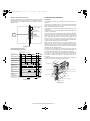
3. Stapling Operation
Offsetting in the backward direction
Aligning plate (rear)
A.Outline
Sheet to be offset
Tray
Aligning plate (front)
Staple operation is performed to staple a specified sheets of paper using
a stapler unit.
The stapling position depends on the staple mode and paper size.
When the machine starts immediately after power-on, the finisher
controller PCB drives the slide motor (FSM) to return the stapler unit to
the home position. The stapler unit starts moving toward the front of the
stapler frame. It stops when the slide home position sensor (SHPS) on
the slide PCB located under the stapler unit. Next, the slide motor is
driven a specified number of pulses. The stapler unit moves to rear
standby position at the back of the machine, entering the standby state.
Sensor
Symbol Connector
Slide home
SHPS
position sensor
Fig.F02-203-04
CN11-3
(4)Stack Delivery Operation
Stack delivery takes place when 10 sheets of large-size paper or 30
sheets of small-size paper (A5- and STMT-sizes: 10 sheets) have been
stacked on the processing tray with them offset in either direction.
The paddle motor rotates and the swing guide descends to hold the
paper stack between the upper and lower stack delivery rollers. The
delivery motor rotates in the forward direction to rotate the delivery
rollers, feeding the paper stack in the delivery direction. The delivery belt
home position sensor is turned OFF. The delivery motor is driven a
specified number of pulses, causing the swing guide to ascend. Next,
the paper delivery motor is driven. Next, the delivery motor is driven to
deliver the paper stack with the nails of the delivery belt that rotates in
sync with the stack delivery rollers.
Function
Remarks
Detects the home
position for the stapler
moving back and forth.
-
Staple home
STHPS CN11-4
position sensor
Detects the home
In the
position for the stapling stapler
operation
Staple empty
sensor
CN11-5
Detects presence or
absence of staples in
the cartridge.
In the
stapler
CN11-6
Detects the staple top
position.
In the
stapler
SPS
Staple top
SS
position sensor
Function
Moves the stapler.
Motor
Slide motor
Performs stapling operation. Staple/fold motor
Symbol
Remarks
FSM
-
FFSM
-
Table.T02-301-01
Stapler
Swing guide
(Deliver direction)
Paper stack
Fig.F02-203-05
Job offset sequence
Slide motor
(FSM)
Light-shielding plate
Start signal
Host machine delivery signal
Inlet sensor (ES)
Slide home position sensor (SHPS)
Processing tray sensor
(AS)
Fig.F02-301-01
Feed motor (FFM)
Delivery motor (FAM)
Delivery belt home
position sensor (OBHPS)
Paddle motor (FPM)
360msec
360msec
360msec
360msec
Paddle home position
sensor (PHPS)
Swing guide home
position sensor (ARHPS)
Stapler safety switch
(SSS)
Alignment motor (front)
(FFJM)
60msec
30msec
220msec
Aligning plate home position
sensor (front) (FJHPS)
Alignment motor (rear)
(FRJM)
Aligning plate home position
sensor (rear) (RJHPS)
CW rotation
CCW rotation
Fig.F02-203-06
AR-F14/PN1 OPERATIONAL DESCRIPTION 4-7
[04]OPERATIONALDESCRIPTION.fm 8 ページ
2004年4月19日 月曜日 午後1時37分
B.Stapling Operation
C.Delivery Operation after Stapling
When stacking and alignment of paper on the processing tray are
complete, the finisher controller PCB drives the paddle motor (FPM) in
the reverse direction and lowers the swing guide. When the swing guide
descends, the paper stack is sandwiched between the upper and lower
stack delivery rollers.
The finisher controller PCB moves the stapler for stapling according to
the specified stapling position (when rear 1-point stapling is specified,
the stapler does not move but it staples at the standby position). As the
stapler moves forward, the processing tray stopper is folded forward.
When stapling is complete, the finisher controller PCB drives the deliver
motor in the forward direction to feed the paper stack (sandwiched
between the stack delivery rollers) in the delivery direction. The delivery
belt home position sensor is turned OFF. The delivery motor is driven a
specified number of pulses, causing the swing guide to ascend. At the
same time, the slide motor is driven to return the stapler back to the
standby position, followed by driving of the delivery motor. Then, the
paper stack is delivered with the nails of the delivery belt that rotates in
sync with the stack delivery rollers.
Paper stack
Paper stack
Swing guide
Stack delivery roller (upper)
Swing guide
Processing tray stopper
Stapler
Delivery tray
Stapler
Delivery tray
Stack
delivery
roller
(lower)
Delivery belt
Stack delivery
roller (lower)
Fig.F02-302-01
Fig.F02-303-01
Swing guide home
position sensor (ARHPS)
Paddle motor (FPM)
Swing guide home
position sensor (ARHPS)
Light-shielding plate
Paddle motor (FPM)
Light-shielding plate
Staple safety switch
(SSS)
Staple safety switch
(SSS)
Swing guide
Stack delivery roller
(upper)
Swing guide
Stack delivery roller
(upper)
Stack delivery roller
(lower)
Stack delivery roller
(lower)
Fig.F02-302-02
Fig.F02-303-02
AR-F14/PN1 OPERATIONAL DESCRIPTION 4-8
[04]OPERATIONALDESCRIPTION.fm 9 ページ
2004年4月19日 月曜日 午後1時37分
D.Stapler Unit
(1)Stapler Movement Controller
The staple/fold motor (FFSM) is used to perform stapling operation. This
motor rotates the cam one turn for stapling. The home position of this
cam is detected by the staple home position sensor (STHPS).
The staple/fold motor is rotated in the forward or reverse direction under
the control of the macro computer (IC13) on the finisher controller PCB.
When the staple home position sensor is OFF, the finisher controller PCB
rotates the staple/fold motor in the forward direction until the sensor turns
ON, allowing the staple cam to the original position.
The staple empty sensor (SPS) is used to detect presence/absence of a
staple cartridge in the machine and presence/absence of staples in the
cartridge.
The stale top position sensor (SS) is used to determine whether staples
are pushed up to the top of the staple cartridge.
The finisher controller circuit does not drive the staple/fold motor (FFSM)
unless the staple safety switch (SSS) is ON (the swing guide is close).
This assures safety in case where you happen to put your finger in the
stapler.
The stapler unit is moved by the slide motor (FSM). Its home position is
detected by the slide home position sensor (SHPS). The stapler waits at
the back irrespective of the staple mode and paper size. After paper has
been stacked on the processing tray, the stapler is moved to the specified
stapling position in response to the stapling command from the host
machine.
F02-304-03 shows the standby position of the stapler and the stapling
position depending on the staple mode.
a.Front 1-point stapling
The stapler waits at the back. The stapler moves to and returns from the
stapling position for each stapling operation.
Standby position
Stapler
Feed direction
Stopper
Stapling position
Fig.F02-304-03
Fig.F02-304-01
b.Rear 1-point stapling
The stapler waits at the back. The stapling position is the same as the
standby position.
Standby position
Stabling position
Stapler
Feed direction
Stopper
Fig.F02-304-04
M7
c.Middle 2-point stapling
Staple/hold motor drive signal
Staple top position detect signal
Staple empty detect signal
Staple home position detect signal
The stapler waits at the back. The stapler moves to and returns from the
stapling position for each stapling operation. The stapler first staples a
paper stack at the rear stapling position and then staples it at the front
stapling position.
Standby position
Stapler
Stapling position
Stopper
Feed direction
Stapling position
Finisher controller PCB
Fig.F02-304-02
Fig.F02-304-05
AR-F14/PN1 OPERATIONAL DESCRIPTION 4-9
[04]OPERATIONALDESCRIPTION.fm 10 ページ 2004年4月19日 月曜日 午後1時37分
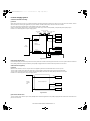
4. Delivery Tray Operation
d.Middle 2-point stapling (bind mode)
The stapler waits at the back. The stapler moves to and returns from the
stapling position for each stapling operation. The stapler first staples a
paper stack at the rear stapling position and then staples it at the front
stapling position.
Standby position
Stapler
Stapling position
Stopper
Feed direction
Stapling position
Fig.F02-304-06
Stapling Operation Sequence
Rear 1-point Stapling of 2 Sheets
Start signal
Host machine delivery signal
Staple Stack delivery
Inlet sensor (ES)
Processing tray sensor
(AS)
Feed motor (FFM)
Delivery motor (FAM)
Delivery belt home
position sensor (OBHPS)
Paddle motor (FPM)
A.Outline
The machine has a delivery tray in the finisher unit and a bind tray in the
saddle unit.
The bind tray in the saddle unit is of the fixed type and all the folded
paper stacks are delivered to this tray. This tray has a bind tray sensor
(FES) to detect presence/absence of paper.
The delivery tray in the finisher unit is moved up and down using a shift
motor (FLM).
The finisher has a tray paper sensor (BES) to detect presence/absence
of paper on the stack tray.
The home position sensor of the delivery tray is detected by the paper
surface sensor (STHPS). When paper has already been stacked on the
delivery tray, the home position is on the top surface of the stacked
paper. When paper has not yet been stacked on the delivery tray, the
home position is at the position where the edge of the delivery tray is
detected. At power-on, the finisher controller PCB drives the shift motor
(FLM) to return the delivery tray to the home position.
When the paper coming from the processing tray is stacked on the
delivery tray, the shift motor is driven a specified number of pulses,
causing the delivery tray to descend. Clock pulses are detected by the
shift motor clock sensor (LE). Then, the delivery tray returns to the home
position for the next stacking operation.
The upper limit of the delivery tray is detected by the shift upper limit
sensor (ULS). When the shift upper limit sensor (ULS) is turned ON, the
finisher controller PCB stops the shift motor (FLM) that is ascending.
The lower limit of the delivery tray is detected by the shift lower limit
sensor (LLLS). When the shift lower limit sensor (LLLS) is turned ON,
the finisher controller PCB stops the shift motor (FLM) that is
descending.
The finisher unit has a full stack sensor (PI24) to detect overstacking of
large-size or mixed paper according to the stack height.
10msec
360msec
360msec
Shift upper limit sensor
(ULS)
Paddle home position
sensor (PHPS)
Swing guide home
position sensor (ARHPS)
Stapler safety switch
(SSS)
Shift lower limit sensor
(LLLS)
Alignment motor (front)
(FFJM)
Tray paper sensor (BES)
Paper surface sensor (SLS)
Aligning plate home position
sensor (front) (FJHPS)
Staple/fold motor
(FFSM)
20msec
Edge
Shift motor clock sensor
(LE)
Staple home position
sensor (STHPS)
Delivery tray
CW rotation
CCW rotation
Full stack sensor (XXXX)
Fig.F02-304-07
Shift motor (FLM)
Fig.F02-401-01
AR-F14/PN1 OPERATIONAL DESCRIPTION 4-10
[04]OPERATIONALDESCRIPTION.fm 11 ページ 2004年4月19日 月曜日 午後1時37分
5. Saddle Unit
b.Stitching
A.Basic Operations
(1)Outline
The machine stitches a stack of sheets (middle 2-point), then folds the
stack in two in the finisher. These operations are controlled by the
finisher controller PCB.
The finisher controller PCB is controlled by the commands from the host
machine.
When the center of the paper stack (stitching position) reaches the
stapler's staple position, the stapler stitches the paper stack.
When only one sheet is fed from the host machine, the next step (stack
feed) is performed without performing the stitching operation.
Staple
Stapler (upper)
B.Feed/Drive System
(1)Outline
This machine stitches the paper stack coming from the finisher, folds it,
and delivers it to the bind tray in the saddle unit in response to the
commands from the host machine.
That is, the machine performs the following operations:
a)
b)
c)
d)
Paper feed-in
Stitching
Stack feed
Folding/delivery
Stapler (lower)
b) Stitching
a) Paper feed-in
Fig.F02-502-03
c) Stack feed
c.Stack feed
The stack feed rollers feed the paper stack to the stack folding/delivery
position where the center of the stack (stitched position) is level with the
paper pushing plate and paper folding roller's nip part.
d) Folding/delivery
Stack feed roller (upper)
Fig.F02-502-01
a.Paper feed-in
Paper pushing plate
After being aligned on the processing tray, a stack of sheets is
sandwiched between the stack delivery rollers. As the stack delivery
rollers rotate, the stack is fed toward the saddle unit.
Stack delivery roller (upper)
Paper stack
Stack delivery roller
(lower)
Stack feed roller (lower)
Paper fold roller
Fig.F02-502-04
Fig.F02-502-02
AR-F14/PN1 OPERATIONAL DESCRIPTION 4-11
[04]OPERATIONALDESCRIPTION.fm 12 ページ 2004年4月19日 月曜日 午後1時37分
d.Folding/delivery
D.Stack Feed System
The paper pushing plate pushes in the center of the paper stack to feed it
toward the paper fold rollers. Then, the paper fold rollers and bind
delivery rollers deliver the paper stack to the bind tray.
(1)Outline
The stack feed system feeds the stitched paper stack to the folding
position.
When stitching is complete, the feed motor (FFM) rotates, causing the
stack feed roller (upper) to descend. The paper stack is sandwiched
between the stack feed rollers. Then, the bind clutch (FFC) is turned ON
to rotate the feed motor (FFM) in the forward direction, thus feeding the
paper stack to the folding position. The feed amount is equivalent to the
number of pulses used to drive the feed motor (FFM) until the paper
stack reaches the folding position.
Stack feed roller (upper)
Fe
e
da
mo
un
t
Bind delivery rollers
Paper fold rollers
Fig.F02-502-05
C.Paper Feed System
(1)Outline
The paper feed system feeds a stack of sheets (coming from the finisher)
to the position where the center of the paper stack (stitching position) is
aligned to the stapler's staple, allowing the next step (stitching and
folding) to be performed.
When sheets of paper have been stacked and aligned on the processing
tray, the paddle motor (FPM) rotates in the reverse direction, causing the
swing guide to descend. As the swing guide descends, the paper stack
is sandwiched between the upper and lower stack delivery rollers. The
delivery motor (FAM) rotates in the reverse direction, feeding the paper
stack toward the saddle unit. When the leading edge of the paper stack
reaches the folding position sensor (FPS), the finisher controller PCB
drives the delivery motor a specified number of motor pulses to stop the
center of the paper stack (stitching position) at the stapler's staple
position. Before the paper stack passes through the stack feed rollers,
the feed motor (FFM) is driven to rotate the stack feed roller (lower) so
that the leading edge of the paper stack is not bent.
Stack delivery roller (upper)
Paper stack
Fold position sensor
Stack delivery roller
(lower)
Stack feed roller (lower)
Fig.F02-504-01
E.Fold/Delivery System
(1)Outline
The paper fold mechanism consists of a guide plate, paper fold rollers,
and a paper pushing plate.
The guide plate, paper fold rollers, and paper pushing plate are driven by
the staple/fold motor (FFSM). The drive force is transferred with a
combination of gears and cams. Motor operation is monitored by the
staple/fold motor lock sensor (FE).
Until the paper stack reaches the folding position, the guide plate covers
the paper fold rollers to act as a paper path through which a paper stack
is fed to the saddle unit and to prevent a paper stack from touching the
rollers.
A folding home position sensor (FHPS) is provided to detect the
positions of the paper fold rollers and paper pushing plate.
The paper stack folded in two by the paper fold rollers is delivered by
bind delivery rollers.
The bind delivery rollers are also driven by the staple/fold motor (FFSM).
A bind tray sensor (FES) is provided on the bind tray to detect presence/
absence of a paper stack; however, it is not used to detect a jam.
Stack feed roller (lower)
Fig.F02-503-01
AR-F14/PN1 OPERATIONAL DESCRIPTION 4-12
[04]OPERATIONALDESCRIPTION.fm 13 ページ 2004年4月19日 月曜日 午後1時37分
(2)Paper Folding
Paper is folded using paper fold rollers and a paper pushing plate.
Almost concurrently with the start of roller rotation, the paper pushing
plate starts operating to push the paper stack into the gap between the
paper fold rollers. When the paper stack is fed about 10 mm with the
rotation of the paper fold rollers, the paper pushing plate returns to the
home position. Then, the paper stack is delivered to the bind tray using
the paper fold rollers and bind delivery rollers.
Half the entire surface of each paper fold roller is uncovered excluding
the central area and the area at the left and right ends. The uncovered
surface of the upper paper fold roller comes in touch with the uncovered
surface of the lower paper fold roller only at the center and left and right
ends, allowing a paper stack to be fed without causing creases. The
other half of the upper paper fold roller that is covered comes in touch
with the other half of the lower paper fold roller that is also covered,
allowing a paper stack to be folded while being fed.
[Paper folding start position]
Paper stack
Inlet
Paper push plate
Outlet
Sensor flag
Folds/feeds a paper stack.
Feeds a paper stack.
Folding home position sensor (FHPS)
Fig.F02-505-03
Came
Paper pushing plate
Paper stack
Staple
Fold, Delivery
Feed motor (FFM)
Paper fold roller (upper)
Delivery motor (FAM)
Paddle motor (FPM)
Staple/fold FFSM
motor
Paddle home position
sensor (PHPS)
Swing guide home
position sensor (ARHPS)
Paper fold roller (lower)
Stapler safety switch
(SSS)
Slide motor (FSM)
13571msec
Staple/fold motor (FFSM)
Fig.F02-505-01
Staple home position
sensor (STHPS)
50msec
Folding position sensor
(FPS)
Stack feed roller (upper)
home position sensor (FRHPS)
Folding
home position sensor (FHPS)
Paper pushing plate
Binding clutch (FFC)
Folding home position
sensor (FHPS)
Bind tray sensor (FES)
Paper fold roller (upper)
CW rotation
Fig.F02-505-04
Staple/fold FFSM
motor
Paper fold roller (lower)
Paper stack
Fig.F02-505-02
AR-F14/PN1 OPERATIONAL DESCRIPTION 4-13
CCW rotation
[04]OPERATIONALDESCRIPTION.fm 14 ページ 2004年4月19日 月曜日 午後1時37分
Punch controller PCB (1/2)
Punch drive system
Horizontal registration
drive system
2
Finisher unit control system
4
Horizontal registration motor
(FPSM) drive signal
The puncher unit is an option, and is designed for installation to the
pickup assembly of the finisher. The puncher unit is not equipped with a
paper feeding mechanism, and the sheets from the host machine move
through the puncher unit and then the feed system of the finisher.
When the trailing edge of a sheet from the host machine reaches the
puncher unit, the sheet is stopped once, and the punch shaft is rotated to
punch a hole along the trailing edge. These operations are controlled
with various commands from the finisher controller PCB as well as the
commands from the punch controller PCB.
Punch motor (FPNM) drive
signal
(1)Outline
Horizontal registration detection
signal (LED1~4, PT1~4) SREG1~4
A. Basic Operations
The punch motor and horizontal registration motor are controlled with
various commands from the finisher controller PCB as well as the
commands from the punch controller PCB.
The waste paper occurring as the result of punching is collected in the
waste paper case. The case is monitored by the LED121 on the waste
full LED PCB and PT131 on the waste full photosensor PCB.
Trailing edge detection signal
(LED5, PT5) PAEND
6. Puncher Unit (option)
PT1
3
5
2
4
LED1
3
5
Punch controller PCB
PT131
Fig.F02-601-01
Punch controller PCB (2/2)
AR-F14/PN1 OPERATIONAL DESCRIPTION 4-14
Fig.F02-602-01
Punch home position (XXXX)
detection signal PUNCHHP
LED121
Waste full detection signal
(LED121, PT131) DFULL
The puncher unit is located in the pickup assembly of the finisher, and is
used to punch holes in sheets that have been sent from the host
machine and stopped inside it. When the trailing edge of a sheet reaches
the puncher unit, the inlet roller of the finisher assembly stops the sheet
to punch a hole along the trailing edge of the sheet.
The punch unit consists of a die and hole puncher (punch blade).
The hole puncher is driven by the punch motor (FPNM). It is attached to
the eccentric cam of the punch shaft, and the rotation of the punch shaft
is converted into reciprocating motion for punching operation.
The punch motor (FPNM) is a DC motor. The home position of the punch
shaft is detected by the punch home position sensor (PI1P). To make
sure that the punch motor, which is a DC motor, stops exactly at its home
position, the punch motor is stopped in relation to the count of the clock
pulses kept by the punch motor clock sensor (PE).
A single punching operation is executed by rotating the punch shaft 180×
from its home position.
As many as five light-receiving transistors (photosensor PCB) are
mounted over the inlet paper path of the puncher unit; on the other hand,
as many as five LEDs (LED PCB) are mounted under the path, together
serving as five sensors. The frontmost sensor (LED5, PT5) is used to
detect the training edge of sheets, and the remaining four (LED1 through
LED4, PT1 through PT4) are used as horizontal registration sensors to
detect the rear position of sheets when punching holes.
The punch motor, punch unit, and sensors make up the punch slide unit,
which moves to the front/rear to suit the selected paper size. The
movement to the front/rear is driven by the horizontal registration motor
(FPSM). The home position of the punch slide unit is detected by the
horizontal registration home position sensor (PSHPS), and the horizontal
registration motor (FPSM) is a stepping motor.
Punch motor clock (PE)
detection signal PUNCHCLK
(1)Outline
Horizontal registration home position
(PSHPS) detection signal SREGHP
B.Punching Operation
[04]OPERATIONALDESCRIPTION.fm 15 ページ 2004年4月19日 月曜日 午後1時37分
(2)Punching Operation
1) A hole is made along the trailing edge of the 1st sheet.
The hole puncher is driven by the punch motor (FPNM). The home
position for the hole puncher is detected by the punch home position
sensor (XXXX).
The punch unit comes in four types, selected to suit the country of
installation: 2-hole (Puncher Unit-J1), 2- and 3-hole (Puncher Unit-K1),
or two types of 4-hole (Puncher Unit-G1, Puncher Unit-H1).
The 2-hole and 4-hole types punch a hole when the punch shaft is
rotated 180× from the home position, causing the punch to make a single
round trip. The 2-/3-hole type punches a hole, but the circumference of
the punch shaft is divided into two (half for 2-hole and the other half for
3-hole).
a.2-Hole, 4-Hole Type
The home position is identified when the punch home position is ON.
The punching operation for the first sheet ends when the punch shaft has
rotated 180× and the punch home position sensor goes ON; the
punching operation for the second sheet ends when the punch shaft has
rotated 180× in reverse and the punch home position sensor goes ON.
The punching operation takes place as follows when making a hole in
two sheets of paper.
Sensor flag
Punch home position
sensor (PI1P)
Punch shaft
Eccentric cam
Hole
puncher
Die
Paper
Die
Waste paper
(punch shaft at rest/
home position)
(punch shaft CW rotation
by 90˚/hole made)
(punch shaft CW rotation by 180˚/
end of punching operation)
Fig.F02-602-04
While two holes are being made, the 3-hole puncher makes a single
round trip in escape direction.
1) A hole is punched along the trailing edge of the 1st sheet.
(punch shaft at rest/
home position)
(punch shaft CW rotation by 90˚/ (punch shaft CW rotation by 180˚/
punch at upper limit)
punch back to initial position)
Fig.F02-602-05
2) Holes are made along the trailing edge of the 2nd sheet.
(punch shaft at rest/
home position)
(punch shaft CCW rotation
by 90˚/hole made)
(punch shaft CCW rotation by 180˚/
end of punching operation)
Fig.F02-602-02
2) A hole is made along the trailing edge of the 2nd sheet.
(punch shaft at rest/
home position)
(punch shaft CCW rotation
by 90˚/hole made)
(punch shaft CCW rotation by 180˚/
end of punching operation)
Fig.F02-602-06
(punch shaft at rest/
home position)
(punch shaft CCW rotation
by 90˚/hole made)
(punch shaft CCW rotation by 180˚/
end of punching operation)
While two hole are being made, the 3-hole puncher makes a single round
trip in escape direction (moving up the hole puncher).
Fig.F02-602-03
b.2- /3-Hole Type
The home position is identified when the punch home position sensor is
ON. To make two holes, the punching operation for the first sheet ends
when the punch shaft rotates 180° (half circumference) and the punch
home position sensor goes ON. At this time, the 3-hole puncher makes a
single round trip in escape direction (moving up the hole puncher) on a
half circumference of the punch shaft.
The punching operation for the second sheet ends when the Punch shaft
has rotated 180° counterclockwise and the punch home position sensor
goes ON (half circumference). At this time, the 3-hole puncher makes a
single round trip in escape direction (moving up the hole puncher) on the
other half circumference of the punch shaft.
The punching operation takes place as follows when making two holes in
two sheets of paper:
(punch shaft at rest/
home position)
AR-F14/PN1 OPERATIONAL DESCRIPTION 4-15
(punch shaft CCW rotation by
90˚/punch at upper limit)
Fig.F02-602-07
(punch CCW rotation by 180˚/
punch back at initial position)
[04]OPERATIONALDESCRIPTION.fm 16 ページ 2004年4月19日 月曜日 午後1時37分
(3)Horizontal Registration Operation
The horizontal registration drive for the punch slide unit is provided by
the horizontal registration motor (FPSM). The home position of the
punch slide unit is detected by the horizontal registration home position
sensor (PSHPS). The punch slide unit detects the trailing edge of sheets
using the trailing edge sensor (LED5, PT5) and the horizontal
registration sensors (LED1 through 4, SREG1 through 4), and causes a
move to a specific position matching the trailing edge of each sheet
(in relation to the size of the sheet).
The horizontal registration operation takes place as follows:
1) When the leading edge of a sheet from the host machine is detected
by the trailing edge sensor (LED5, PT5), the horizontal registration
motor (FPSM) starts to move the punch slide unit toward the front.
4) When the punching operation ends, the feed motor (FFM) of the
fisher unit is driven and, at the same time, the horizontal registration
motor (FPSM) is rotated in reverse to return the punch slide unit to its
home position.
5) For each sheet that arrives in succession, the punch slide unit is
returned to its home position, and is caused to repeat steps 1
through 4 .
Trailing edge sensor
(LED5, PT5)
Horizontal registration
sensor (LED1~4, PT1~4)
Punch home position
sensor (XXXX)
Horizontal registration home
position sensor (PSHPS)
Horizontal registration
motor (FPSM)
Punch slide unit
Punch motor (FPNM)
Horizontal registration
motor (M2P)
Feed motor (FFM)
Trailing edge sensor
(LED5, PT5)
: CW rotation
: CCW rotation
Fig.F02-602-11
7. Detecting Jams
(direction of
paper delivery)
Paper
Fig.F02-602-08
A.Outline
The microprocessor (CPU) on the finisher controller PCB is programmed
to check for jams in the finisher/saddle/puncher (option) at such times as
set in advance. It identifies a jam in reference to the presence/absence of
paper at a specific sensor. If a jam is found, the finisher controller PCB
communicates the nature of the jam to the host machine in the form of a
code(which may be checked in service mode of the host machine).
2) When the horizontal registration sensor (LED1 through 4, PT1
through) suited to the paper size signal from the host machine
detects the rear edge of the sheet, the horizontal registration motor
(FPSM) causes a farther move to a specific position, and stops the
punch slide unit.
ES
Horizontal registration sensor (LED1, PT1);
used to detect the edge of sheets of A3, A4,
LTR, 279×432 (11"×17").
Horizontal registration sensor 2 (LED2, PT2);
used to detect the edge of sheets of B4, B5,
LTRR, LGL.
Horizontal registration sensor 3 (LED3, PT3);
used to detect the edge of sheets of A4R.
FPS
Horizontal registration sensor 4 (LED4, PT4);
used to detect the edge of sheets of B5R.
Fig.F02-602-09
3) When the trailing edge sensor (LED5, PT5) detects the trailing edge
of the sheet, the drive of the feed motor (FFM) is stopped, thereby
stopping the sheet. Then, the punch motor (FPNM) is driven to
punch holes in the sheet.
ES: inlet sensor.
FPS Folding position sensor
Punch
Fig.F02-602-10
AR-F14/PN1 OPERATIONAL DESCRIPTION 4-16
Fig.F02-701-01
[04]OPERATIONALDESCRIPTION.fm 17 ページ 2004年4月19日 月曜日 午後1時37分
(1)Inlet Sensor Delay Jam (1011)
The inlet sensor does not detect paper approximately 1.5 sec after the host machine generates the delivery signal.
Host machine delivery signal
Host machine delivery signal
approx. 1.5sec.
approx. 1.5sec.
Jam check
Jam check
Normal
Inlet sensor (ES)
Jam
Inlet sensor (ES)
Feed motor (FFM)
Feed motor (FFM)
Fig.F02-701-02
(2)Inlet Sensor Stationary Jam (1021)
The paper does not leave the inlet sensor approximately 2 sec after the inlet sensor has detected its leading edge.
Jam check
approx. 2sec.
Jam check
Normal
Inlet sensor (ES)
Feed motor (FFM)
approx. 2sec.
Jam
Inlet sensor (ES)
Feed motor (FFM)
Fig.F02-701-03
(3)Folding Position Sensor Delay Jam (1012)
In bind mode, the folding position sensor does not detect paper 1200 msec after the intermediate processing tray starts to send paper to the stapling
position.
1200 ms
1200 ms
Jam check
Folding position
sensor (FPS)
Jam check
Folding position
sensor (FPS)
Normal
Delivery motor (FAM)
Jam
Delivery motor (FAM)
Fig.F02-701-04
(4)Folding Position Sensor Stationary Jam (1022)
In bind mode, paper does not leave the holding position sensor approximately 10.5 sec after the staple/fold motor is driven.
approx. 10.5sec.
approx. 10.5sec.
Jam check
Folding position
sensor (FPS)
Staple/fold
motor (FFSM)
Jam check
Normal
Folding position
sensor (FPS)
Jam
Staple/fold
motor (FFSM)
Fig.F02-701-05
(5)Power-On Jam (1007)
Paper is detected inside the finisher at power-on or when the door is closed.
(6)Door Open Jam (paper present) (1008)
The finisher is disconnected from its host machine or the front door, or the upper cover is opened while the system is in operation (paper on the move).
(7)Staple Jam (1006)
The staple home position sensor (STHPS) does not go OFF 600 msec after the stapler is driven. Or, it does not return to its home position (where the
sensor goes ON).
AR-F14/PN1 OPERATIONAL DESCRIPTION 4-17
[04]OPERATIONALDESCRIPTION.fm 18 ページ 2004年4月19日 月曜日 午後1時37分
8. Power Supply System
A.Finisher/Saddle Assembly
(1)Outline
When the host machine is turned on, it supplies the finisher controller PCB with two channels of 24 VDC; one is for the motors and clutches, and the
other is turned into 5 VDC by the regulator IC (IC1) of the finisher controller PCB for use by the sensors and ICs on PCBs.
If a punch unit (option) is installed, power is also supplied to the punch controller PCB.
Some of 24 VDC used to drive motors is cut off when the joint switch (JS), front door switch (FDSW), or stapler safety switch (SSS) is open.
F02-801-01 is a block diagram of the power supply system:
Joint switch
(JS)
Front door switch
(FDSW) Stapler safety switch
(SSS)
24 V
24 V
Motor
Motor
24VP
24 V
Circuit Breaker
(CB1)
Clutch
Finisher
controller PCB
Host
machine
5V
Sensor
(IC1)
24VL
5V
Regulator IC
Logic system
Punch controller PCB
(puncher unit; option)
Fig.F02-801-01
(2)Protective Mechanisms
A circuit breaker (CB1) is monitored to protect the 24 VDC system sued to drive the motors against overcurrent. The 24-V system used to drive the feed
motor (FFM), paddle motor (FPM), and delivery motor (FAM) is equipped with a fuse which melts in the presence of overcurrent.
A.Puncher Unit (option)
(1)Outline
When the host machine is turned on, the puncher unit is supplied by the finisher controller PCB with 24-V and 5-V power.
The 24-V power is used to drive the motors, while the 5-V power is used by sensors and the ICs on the punch controller PCB.
The 24-V power to the motors will be cut off when the joint switch (MS2) or the front door switch (MS1) of the finisher unit is open.
F02-802-01 is a block diagram for the power supply system:
24 V
Finisher
controller
PCB
24 V
Motors
Punch controller PCB
5V
5V
5V
Sensors
Logic system
Fig.F02-802-01
(2)Protective Mechanisms
The 24-V system used to drive the punch motor (FPNM) and the horizontal registration motor (FPSM) is equipped with a built-in fuse which melts in the
presence of overcurrent.
AR-F14/PN1 OPERATIONAL DESCRIPTION 4-18
[05]DISASSEMBLYANDASSEMBLY.fm 1 ページ
2004年4月19日 月曜日 午後1時38分
[5] DISASSEMBLY AND ASSEMBLY
4) Remove the three screws [5], and detach the front cover [6].
[6]
1. Finisher Saddle Unit
A. Externals and Controls
[1]
[5]
[6]
[2]
[5]
[7]
[5]
[4]
Fig.F03-101-04
(3)Removing the Rear Cover
[3]
1) Remove the two screws [1] on the pickup side, and remove the screw
[2] on the delivery side; then, detach the rear cover [3].
Fig.F03-101-01
(1)Removing the Delivery Tray
1) Remove the four screws [1], and detach the delivery tray [2].
[3]
[2]
[1]
Fig.F03-101-05
[1]
Fig.F03-101-02
[3]
(2)Removing the Front Cover
1) Open the front door [1].
2) While picking the claw [2], detach the fold jam releasing dial [3].
3) Remove the two screws [4].
[1]
[4]
[2]
Fig.F03-101-06
(4)Removing the Upper Cover
[3]
1) Open the upper cover [1], and turn the cover band retainer [2] to the
left to remove it.
2) Remove the cover band [3].
[1]
[2]
[4]
Fig.F03-101-03
[3]
Fig.F03-101-07
AR-F14/PN1 DISASSEMBLY AND ASSEMBLY 5-1
[2]
[05]DISASSEMBLYANDASSEMBLY.fm 2 ページ
2004年4月19日 月曜日 午後1時38分
3) Remove the screw [4], and detach the processing tray rear cover [5];
then, detach the upper.
[6]
(6)Removing the Upper Right Cover Assembly
1) Remove the front cover. (See 1.A.(2).)
2) Remove the rear cover. (See 1.A.(3).)
3) Remove the two screws [1] at the front and the two screws [2] at the
rear; then, detach the upper right cover assembly [3].
[3]
[1]
[5]
Fig.F03-101-11
[4]
Fig.F03-101-08
(5)Removing the Processing Tray Upper Cover
1)
2)
3)
4)
[3]
Remove the front cover. (See 1.A.(2).)
Remove the rear cover. (See 1.A.(3).)
Remove the upper cover. (See 1.A.(4).)
Disconnect the connector [1], and remove the screw [2].
[2]
Fig.F03-101-12
(7)Removing the Saddle Guide
1)
2)
3)
4)
Remove the delivery tray. (See 1.A.(1).)
Remove the front cover. (See 1.A.(2).)
Remove the rear cover. (See 1.A.(3).)
Free the delivery tray support plate (front) [1] and the delivery tray
support plate (rear) [2] to the outside from the rail grooves.
5) Remove the four screws [3].
[3]
[2]
[3]
[2]
[1]
[1]
[3]
[3]
Fig.F03-101-09
5) While lifting the processing tray upper cover [3], disconnect the
connector [4]; then, detach the processing tray upper cover [3].
Fig.F03-101-13
6) Shift the side guide [4] lightly to the front, and free the engagement
of the paper surface detecting lever (rear) [5]; then, detach the side
guide [4].
[3]
[5]
[4]
[4]
Fig.F03-101-14
Fig.F03-101-10
AR-F14/PN1 DISASSEMBLY AND ASSEMBLY 5-2
[05]DISASSEMBLYANDASSEMBLY.fm 3 ページ
2004年4月19日 月曜日 午後1時38分
NOTE: Be sure to mount the side guide after securely fitting the paper
surface detecting lever (rear) [5] in the groove of the paper
surface detecting lever (middle) [6].
After completion of mounting, push the paper surface detecting
lever several times to make sure that side guide is mounted
securely.
(2)Adjusting the Stapler Phase
When the gears or timing belt at the front of the stapler is replaced or
removed for some reason, the staple shooting timing of the (lower unit of
the stapler) does not match the staple bending timing of the staple
clincher (upper unit of the stapler). Adjust the stapler phase following the
procedure described below.
Gear
[5]
[6]
Timing belt
[5]
Gear
Fig.F03-102-03
[6]
1) Detach the gear cover [2] from the staple driver [1].
2) Remove the E-ring [3] to detach the side cover [5] of the staple
clincher [4].
Fig.F03-101-15
[4]
B.Feeding System
(1)Removing the Stapler Unit
1) Open the front door [1].
2) Slide out the stapler unit [3] while pressing the stopper [2].
[3]
[1]
[5]
[2]
[1]
[3]
Fig.F03-102-04
3) Remove the two E-rings [6] to remove the staple jam releasing gear
[7], timing belt [8], and relay gear 1 [9]. Remove the spacer and
spring at the back of the staple jam releasing gear.
4) Remove the screw [10] and spring [11] to remove the belt tensioner
[12].
[2]
[7]
Fig.F03-102-01
NOTE: Do not remove the stapler stapler frame shaft. If removed, the
position where the staple driver (lower unit of the stapler) [4]
shoots stables will shift from the position where the staple
clincher (upper unit of the stapler) [5] receives staples.
[8]
[6]
[9]
[5]
[11]
[10]
[4]
[12]
Fig.F03-102-05
Fig.F03-102-02
AR-F14/PN1 DISASSEMBLY AND ASSEMBLY 5-3
[05]DISASSEMBLYANDASSEMBLY.fm 4 ページ
2004年4月19日 月曜日 午後1時38分
5) Remove the timing belt [13].
6) Remove the E-ring [14] to remove the staple position check gear
[15].
9) Turn the gear [19] to align the round hole in the staple clincher cam
with the round hole [20] at the back.
[19]
[15]
[14]
[13]
Fig.F03-102-06
7) Turn the gear [16] to align the round hole in the staple driver gear
with the round hole [17] at the back.
[20]
Fig.F03-102-09
10) Insert a pin [21] with a diameter of approximately 2 mm (use of a 2
mm Allen wrench is recommended) in the round hole to secure the
gear.
[16]
[17]
[21]
Fig.F03-102-10
Fig.F03-102-07
8) Insert a pin [18] with a diameter of approximately 2 mm
(use recommended) in the round hole to secure the gear.
11) With the gears and cam fixed, install the timing belt [22] on gears [23]
and [24].
[23]
[18]
[22]
Fig.F03-102-08
[24]
Fig.F03-102-11
AR-F14/PN1 DISASSEMBLY AND ASSEMBLY 5-4
[05]DISASSEMBLYANDASSEMBLY.fm 5 ページ
2004年4月19日 月曜日 午後1時38分
12) Mount the staple position check gear [27] so that the blue mark [25]
on the staple position check gear is aligned with the round hole [26]
in the frame.
[26]
(3)Adjusting the Phase of the Gear in the Saddle Unit
If the gears at the front of the saddle unit or the paper fold rollers in the
sale unit are replaced or removed for some reason, adjust the gear
phase following the procedure described below.
1) The paper fold rollers [1] and saddle cam [2] must be positioned as
shown below.
[25]
[2]
[27]
[1]
Fig.F03-102-12
NOTE: The position where the blue mark is aligned with the round hole is
the home position for stapling. If the staple jam cancel dial is
turned for some reason, the home position deviates, making it
impossible to remove the stapler cartridge. If such a case, the
gear can be returned to the home position by checking blue mark
position. Therefore, it is necessary to mount the gear at the
correct position.
13) Remove the pin securing the gear to the cam.
14) Assemble the spring [28], spacer [29], staple jam releasing gear [30],
timing belt [31], and relay gear [32] and secure them with the E-ring
[33].
[28]
Fig.F03-102-14
2) With the paper fold rollers and saddle cam positioned as shown in
Figure F03-102-14, mount gears as shown in figure F03-102-15.
•Align the
mark (either of two
marks) on the saddle cam drive
gear [3] with the
mark on the relay gear [4] (on the half of the
periphery where gears with a smaller face width are arranged).
•With the
mark on the saddle cam drive gear [3] aligned with the
mark on the relay gear [4], align the other
mark on the relay gear
withy the rib of the paper folding roller drive gear [5].
[31]
[3]
[29]
[4]
[32]
[5]
[33]
[30]
Fig.F03-102-13
Fig.F03-102-15
AR-F14/PN1 DISASSEMBLY AND ASSEMBLY 5-5
[05]DISASSEMBLYANDASSEMBLY.fm 6 ページ
2004年4月19日 月曜日 午後1時38分
(4)Removing the Saddle Unit
(5) Removing the Processing Tray Assembly
1) Remove the front cover. (See 1.A.(2).)
2) Remove the rear cover. (See 1.A.(3).)
3) Open the jam removal cover [1]; then, remove the two screws [2] and
the right stay [3].
1) Remove the processing tray upper cover. (See 1.A.(5).)
2) Remove the side guide. (See 1.A.(7).)
3) Remove the two screws [1], and disconnect the five connectors [2].
[1]
[3]
[2]
[2]
[2]
[1]
[2]
[1]
[2]
Fig.F03-102-20
Fig.F03-102-16
4) Turn the fold jam releasing dial assembly [4] to move the paper
retaining plate assembly [5] to the inside.
4) Pull the processing stopper base [3] to the front, and free the claw [5]
at the front and the claw [6] at the rear of the processing stopper [4].
[5]
[6]
[5]
[4]
[4]
[4]
[3]
Fig.F03-102-17
5) Remove the stop ring [6], and detach the timing belt [7].
6) Disconnect the two connectors [8].
[6]
[7]
Fig.F03-102-21
5) Disconnect the three connectors [7].
6) Release the two claws [8] of the harness retainer, and detach the
motor harness [9].
[8]
Fig.F03-102-18
7) Remove the three screws [9], and slide out the stapler unit [10]
slightly to the front.
8) Slide out the saddle unit [11] to the front.
[10]
[9]
[9]
[8]
[7]
Fig.F03-102-22
[9]
[11]
Fig.F03-102-19
AR-F14/PN1 DISASSEMBLY AND ASSEMBLY 5-6
[05]DISASSEMBLYANDASSEMBLY.fm 7 ページ
2004年4月19日 月曜日 午後1時38分
7) Remove the stop ring [10], and detach the timing belt [11].
8) Disconnect the connector [12], and free the harness [14] from the
edge saddle [13].
(6) Removing the Paddle Assembly
1) Remove the processing tray assembly. (See 1.B.(3).)
2) Place the processing tray assembly [1] as shown.
NOTE: Be sure to take care not to damage the aligning plate [2].
[1]
[2]
[12]
[11]
[14]
[10]
Fig.F03-102-25
3) Detach the timing belt [3], and remove the two screws [4].
[4]
[13]
Fig.F03-102-23
9) Remove the two screws [15], and slide the processing tray assembly
[16] to the rear; then, lift it to detach.
[16]
[15]
[3]
Fig.F03-102-24
[4]
Fig.F03-102-26
4) Separate the processing tray assembly [5] and the paddle assembly
[6] as shown.
[6]
[5]
Fig.F03-102-27
AR-F14/PN1 DISASSEMBLY AND ASSEMBLY 5-7
[05]DISASSEMBLYANDASSEMBLY.fm 8 ページ
2004年4月19日 月曜日 午後1時38分
(7)Removing the Staple/Fold Drive Unit
1) Open the front door [1], and slide out the stapler unit [2] slightly to the
front.
9) Remove the screw [15], and free the claw [17] of the harness guide
from the long angle [16] of the base plate.
[15]
[2]
[1]
[16]
[17]
Fig.F03-102-31
10) Disconnect the two connectors [18], and free the harness [20] from
the edge saddle [19].
Fig.F03-102-28
2)
3)
4)
5)
Remove the screw [3], and detach the interface retainer [4].
Free the six harness retainers [5], and disconnect the connector [6].
Free the harness [7] from the harness retainer [5].
Free the harness [7] from the edge saddle [8]; then, disconnect the
two connectors [9].
[18]
[20]
[9]
[18]
[19]
Fig.F03-102-32
11) Remove the three screws [21].
[8]
[7]
[21]
[21]
[5]
[6]
[7]
[3]
[5]
[7]
[4] [5] [7] [5]
Fig.F03-102-29
6) Release the harness retainer [10], and disconnect the connector
[11].
7) Free the harness [12] from the harness retainer [10].
8) Free the harness [12] for the edge saddle [13]; and disconnect the
two connectors [14].
[21]
Fig.F03-102-33
12) Remove the screw [22], and detach the staple/fold drive unit [23].
[14]
[11]
[12]
[13]
[10]
[22]
Fig.F03-102-30
[23]
Fig.F03-102-34
AR-F14/PN1 DISASSEMBLY AND ASSEMBLY 5-8
[05]DISASSEMBLYANDASSEMBLY.fm 9 ページ
2004年4月19日 月曜日 午後1時38分
(8)Removing the Feed Motor Unit
1)
2)
3)
4)
Remove the rear cover. (See 1.A.(3).)
Open the harness retainer [1], and disconnect the two connectors [2].
Remove the screw [3], and detach the harness guide [4].
Remove the three screws [5], and detach the feed motor unit [6].
7)
8)
9)
10)
Remove the gear [5], and detach the gear [6] while spreading the claw.
Remove the stop ring [7], and detach the bushing [8].
Remove the screw [9], and detach the inlet sensor [10].
Remove the lower paper guide [11].
[8]
[5]
[5]
[9]
[5]
[10]
[7]
[3]
[6]
[11]
[4]
[6]
[2]
[1]
Fig.F03-102-38
Fig.F03-102-35
11) Remove the feed roller [12].
(9)Removing the Feed Roller
1)
2)
3)
4)
5)
Remove the upper cover. (See 1.A.(4).)
Remove the upper right cover assembly. (See 1.A.(6).)
Remove the feed motor unit. (See 1.B.(6).)
Remove the screw [1].
Remove the stop ring [2], and detach the bushing [3].
[12]
Fig.F03-102-39
(10)Removing the Stack delivery roller (upper)
1) Remove the paddle assembly. (See 1.B.(4).)
2) Place the paddle assembly [1] as shown.
[1]
[1] [3]
[2]
Fig.F03-102-36
Fig.F03-102-40
6) Remove the two screws [4].
[4]
3) Turn the gear [2] in the direction of the arrow to move up the stack
delivery roller assembly (upper) [3].
[3]
[2]
Fig.F03-102-37
Fig.F03-102-41
AR-F14/PN1 DISASSEMBLY AND ASSEMBLY 5-9
[05]DISASSEMBLYANDASSEMBLY.fm 10 ページ 2004年4月19日 月曜日 午後1時38分
4) Push up the stack delivery roller (upper) [4] from below to free the
stack deliver roller (upper) [4] from the shaft [5].
4) Push up the safety guide [4] from below to free one side of the safety
guide [4] from the shaft [5].
[4]
[5]
[5]
[4]
Fig.F03-102-42
5) Shift up the stack delivery roller (upper) [4], and then push it down to
detach the stack deliver roller (upper) [4].
6) Likewise, remove the stack delivery roller (upper) [6] at the front.
[6]
Fig.F03-102-46
5) Push up the safety guide [4] from below to free the safety guide [4]
from the shaft [5].
[4]
[4]
[5]
Fig.F03-102-43
(11) Removing the Paddle
Fig.F03-102-47
1) Remove the paddle assembly. (See 1.B.(4).)
2) Place the paddle assembly [1] as shown.
6) Remove the paddle [6] in the direction of the arrow.
7) Likewise, remove the other paddle.
[1]
[1]
Fig.F03-102-44
Fig.F03-102-48
3) Turn the gear [2] in the direction of the arrow to move up the stack
delivery roller assembly (upper) [3].
[3]
[2]
Fig.F03-102-45
AR-F14/PN1 DISASSEMBLY AND ASSEMBLY 5-10
[05]DISASSEMBLYANDASSEMBLY.fm 11 ページ 2004年4月19日 月曜日 午後1時38分
(12)Removing the Stack delivery roller (lower)/Delivery Belt
1) Remove paddle assembly, and separate it from the processing tray
assembly. (See 1.B.(4).)
2) Slide the aligning plate (front) [2] and the aligning plate (rear) [3] of
the processing tray assembly [1] by sliding them to the outside.
[1]
6) Remove the two stop rings [11]; then, move the two bushings [12] to
the inside.
[12]
[11]
[3]
[11]
[12]
Fig.F03-102-53
[2]
7) Remove the four screws [13]; then, lift the stack delivery roller
assembly (lower) [14] to detach.
Fig.F03-102-49
3) Remove the processing tray stopper [4].
[13]
[4]
[13]
[14]
Fig.F03-102-54
8) Remove the stack delivery roller (lower) [15] and the two delivery
belts [16].
Fig.F03-102-50
4) Remove the screw [5], and detach the paper guide (front) [7] while
freeing the two claws [6].
[16]
[5]
[7]
[15]
[6]
Fig.F03-102-55
NOTE: Be sure to mount them so that the edges [17] of the claws of the
delivery belts are flush.
Fig.F03-102-51
5) Remove the screw [8]; then, while freeing the claw [9], detach the
paper guide (rear) [10].
[17]
[8]
[10]
[9]
Fig.F03-102-56
Fig.F03-102-52
AR-F14/PN1 DISASSEMBLY AND ASSEMBLY 5-11
[05]DISASSEMBLYANDASSEMBLY.fm 12 ページ 2004年4月19日 月曜日 午後1時38分
C. PCBs
(1)Removing the Finisher Controller PCB
1) Remove the rear cover. (See 1.A.(3).)
2) Disconnect the 17 connectors [1], and remove the screw [2].
3) Free the PCB retainer [3], and detach the finisher controller PCB [4].
[2]
5) Turn the tab [2] on the stapler side in the direction of the arrow so
that that the fixing screw [7] of the slide home position PCB [6] is in
view through the round hole.
6) Remove the fixing screw [7].
[2]
[3]
[6]
[1]
[1]
[1]
[7]
[4]
Fig.F03-103-01
(2)Removing the Slide Home Position PCB
1) Open the front door [1], and turn the tab [2] on the stapler slide in the
direction of the arrow to slide the stapler to the frontmost point.
2) Remove the stapler unit. (See 1.B.(1).)
[1]
Fig.F03-103-04
7) Disconnect the connector [8].
8) Remove the flexible cable retainer [9].
9) Free the lock [10] of the connector in the direction of the arrow; then,
detach the flexible cable [11], and then detach the side home
position PCB [12].
[8]
[10]
[11]
[2]
[12]
Fig.F03-103-02
[9]
3) Place the stapler unit [3] as shown.
4) Remove the two screws [4], and detach the guide [5].
[3]
[4]
[5]
[4]
Fig.F03-103-03
AR-F14/PN1 DISASSEMBLY AND ASSEMBLY 5-12
Fig.F03-103-05
[05]DISASSEMBLYANDASSEMBLY.fm 13 ページ 2004年4月19日 月曜日 午後1時38分
D. Interface transport section
d. No. 2 paper exit sensor
(1) Decolor unit
1) Remove the No. 2 paper exit sensor, and remove the connector.
a. Rear cabinet
1) Remove the screw (1 pc), and remove the maintenance cover.
2) Remove the four screws, and remove the rear cabinet.
Maintenance cover
e. Tray detection switch
Rear cabinet
1) Remove the tray detection switch, and remove the connector.
b. Right cabinet
1) Open the manual feed tray.
2) Open the right door.
3) Remove the two screws, and remove the right cabinet.
f. DUP paper exit roller
1) Remove the screw, and remove the frame unit.
c. Decolor unit
1) Remove the connector of the decolor from the main unit.
2) Remove the four screws, and remove the decolor unit.
2) Remove the gear and the bearing. Remove the E-ring and the
bearing, and remove the DUP paper exit roller.
AR-F14/PN1 DISASSEMBLY AND ASSEMBLY 5-13
[05]DISASSEMBLYANDASSEMBLY.fm 14 ページ 2004年4月19日 月曜日 午後1時38分
g. Decolor roller
1) Remove the frame unit.
2) Remove the E-ring, the gear, and the bearing. Remove the decolor
roller.
7) Pull out the transport unit to the copier unit guide.
8) Remove the docking unit connector, and pull it out.
copier unit guide
8
7
*
When removing or attaching the roller, be careful of the actuator.
b. Paper entry sensor 1
1) Remove the paper entry sensor 1, and remove the connector.
(2) Interface transport unit
a. Docking unit
1) Remove the screw, and slide the upper cover as shown in the figure.
2) Remove the screws C from the upper side of the front cover, and
remove the front cover and the docking unit.
3) Remove the two screws and remove the front cover.
4) Remove the four screws, and remove the left cover.
2
1
c. Photo sensor
4
1) Remove the photo sensor, and remove the connector.
3
5) Open the transport unit cover.
6) Remove the two screws A (M4 x 10).
d. Paper entry sensor 2
1) Remove the paper entry sensor 2, and remove the connector.
6
5
6
AR-F14/PN1 DISASSEMBLY AND ASSEMBLY 5-14
[05]DISASSEMBLYANDASSEMBLY.fm 15 ページ 2004年4月19日 月曜日 午後1時38分
e. Interface transport motor
3) Remove the interface transport lower unit.
1) Remove the connector and the screw, and remove the interface
transport motor.
f. Interface transport drive motor
1) Remove the jam release spring.
4) Remove the interface transport earth wire.
2) Pull the notch and release the lock, and raise the interface transport
upper unit.
5) Remove the E-ring, the belt, and the pulley. Remove the manual feed
auxiliary roller unit.
6) Remove the connector, the earth wire, and the screw. Remove the
interface transport motor unit. Remove the E-ring and the gear.
AR-F14/PN1 DISASSEMBLY AND ASSEMBLY 5-15
[05]DISASSEMBLYANDASSEMBLY.fm 16 ページ 2004年4月19日 月曜日 午後1時38分
7) Remove the E-ring, and remove the interface transport drive roller
unit. Remove the bearing from the interface transport drive roller.
h. Interface transport medium roller 3
1) Remove the interface transport lower unit.
2) Remove the interface transport earth wire.
3) Remove each part. Remove the manual feed auxiliary roller unit.
g. Interface transport medium roller 1, 2
1) Remove the interface transport lower unit.
2) Remove the interface transport earth wire.
3) Remove each part. Remove the manual feed auxiliary roller unit.
4) Remove the screw, and remove the transport paper guide.
4) Remove the E-ring, and remove the interface transport medium roller
unit 1 and 2. Remove the bearing from the interface transport
medium roller 1 and 2.
5) Remove the E-ring, and remove the interface transport medium roller
unit 3. Remove the bearing from the interface transport medium
roller unit 3.
AR-F14/PN1 DISASSEMBLY AND ASSEMBLY 5-16
[05]DISASSEMBLYANDASSEMBLY.fm 17 ページ 2004年4月19日 月曜日 午後1時38分
2. Puncher Unit (option)
3) Disconnect the connector [3]
4) Remove the harness [5] from the harness guide [4].
A.Puncher Driving System
(1)Removing the Punch Motor
[3]
1) Remove the two screws [1].
2) Disconnect the connector [2] to remove the punch motor [3].
[2]
[5]
[4]
Fig.F03-201-04
[1]
5) Disconnect the connector [6].
6) Remove the screw [7] and sensor support plate [8].
[3]
[6]
Fig.F03-201-01
(2)Removing the Horizontal Registration Motor
1) Disconnect connector [1].
2) Remove the harness [3] from the harness guide [2].
3) Remove the two screws [4] to remove the horizontal registration
motor [5].
[4]
[8]
[7]
Fig.F03-201-05
[3]
7) Remove the screw [9] and washer [10].
8) Disconnect the connector [11].
9) Remove the two screws [12] to detach the base cover [13].
[1]
[2]
[5]
[9]
Fig.F03-201-02
(3)Removing the Punch Unit
1) Remove the waste case.
2) Remove the screw [1] to detach the jam processing cover [2].
[1]
[10]
[2]
[13]
[11]
[12]
Fig.F03-201-03
Fig.F03-201-06
AR-F14/PN1 DISASSEMBLY AND ASSEMBLY 5-17
[05]DISASSEMBLYANDASSEMBLY.fm 18 ページ 2004年4月19日 月曜日 午後1時38分
10)Remove the four screws [14] to remove the upper transmission
sensor unit [15] and lower transmission sensor [16].
[15]
B. PCBs
(1)Removing the Punch Controller PCB
1) Remove the two screws [1].
2) Disconnect the five connectors [2] to remove the punch controller
PCB [3].
[2]
[14]
[14]
[16]
[3]
[2]
[14]
Fig.F03-201-07
11) Remove the punch unit [18] from the horizontal registration motor
assembly [17].
[17]
[18]
[2]
[1]
Fig.F03-202-01
Fig.F03-201-08
(2)Removing the Photosensor PCB
1) Remove the punch motor. (See 2.A.(1).)
2) Remove the screw [1].
3) Remove the harness [3] from the harness guide [2] on the PCB, then
detach the PCB cover [4].
[4]
[1]
[3]
[2]
Fig.F03-202-02
4) Disconnect the connector [5] to remove the photosensor PCB [6].
[6]
[5]
Fig.F03-202-03
AR-F14/PN1 DISASSEMBLY AND ASSEMBLY 5-18
[05]DISASSEMBLYANDASSEMBLY.fm 19 ページ 2004年4月19日 月曜日 午後1時38分
(3)Removing the LED PCB
(4)Removing the Waste-Full Photosensor PCB
1) Remove the waste case.
2) Disconnect connector [1].
3) Remove the harness [3] from the harness guide [2].
1) Remove the punch controller PCB. (See 2.B.(1).)
2) Remove the two screws [1] to remove the PCB film [2].
[1]
[2]
[3]
[1]
[2]
Fig.F03-202-07
Fig.F03-202-04
4) Remove the screw [4] and washer [5].
5) Disconnect the connector [6].
6) Remove the screw [7] to detach the base cover [8].
[4]
3) Disconnect the connector [3] to remove the waste-full photosensor
PCB [4].
[3]
[4]
[5]
Fig.F03-202-08
(5)Removing the Waste Full LED PCB
[8]
[6]
1) Remove the screw [1].
2) Disconnect the connector [2] to remove the waste-full LED PCB [3].
[7]
[2]
[1]
[3]
Fig.F03-202-09
Fig.F03-202-05
7) Remove the screw [9].
8) Disconnect the connector [10] to remove the LED PCB [11].
[10]
[9]
[11]
Fig.F03-202-06
AR-F14/PN1 DISASSEMBLY AND ASSEMBLY 5-19
[06]MAINTENANCE.fm 1 ページ
2004年4月19日 月曜日 午後1時40分
[6] MAINTENANCE
1. Maintenance System Table
Check (Clean, replace, or adjust as necessary.)
Unit name
Transport section
Part name
When
calling
Clean
75K
Replace
Adjust
Lubricate
150K 225K 300K 375K 450K
Move position
Remark
Transport rollers
Transport paper
guides
Drive section
Gears
(Specified position)
Belts
Other
Sensors
Discharge brush
Staple un
Replace UN at 100K staple.
Staple cartridge
User replacement for every 3000pcs.
2. Discarding punch waste (when a punch unit is installed)
1) Press the detach button and separate the saddle stitch finisher from
the machine.
3) Replace the punch waste receptacle.
4) Push the saddle stitch finisher back onto the machine.
Caution: The saddle stitch finisher and the machine are connected at
the rear. Exercise caution when pulling them apart.
2) Gently pull the punch waste receptacle forward and discard the
punch waste.
Empty the punch waste receptacle into a garbage bag or other container,
taking care not to let punch waste scatter.
AR-F14/PN1 MAINTENANCE 6-1
[07]MACHINEOPERATION.fm
1 ページ 2004年4月19日 月曜日 午後1時41分
[7] MACHINE OPERATION
1. Staple sort mode
Collated sets of printouts are stapled and delivered to the offset tray (upper tray). Alternatively, printed paper is stapled at the center and delivered to
the saddle stitch tray (lower tray). The relation among stapling positions, orientation, paper size for stapling, and stapling capacity is shown below.
Stapling positions
Portrait orientation
Landscape orientation
Rear corner of
printouts
Available paper sizes: 8-1/2"
x 11", A4 and B5
Stapling capacity: Up to 50
sheets for any sizes
Center left two
positions of
printouts
Same as above
Same as above
Front corner of
printouts
Same as above
Same as above
Saddle stitch
Saddle stitch stapling cannot
be performed in the portrait
orientation.
Available paper sizes: 11" x
17", 8-1/2" x 11"R, A3, B4,
and A4R
Stapling capacity: Up to 10
sheets for any sizes
Available paper sizes: 11" x 17",
8-1/2" x 14", 8-1/2" x 13", 8-1/2"
x 11" R, A3, B4, A4R, and B5R
Stapling capacity: Up to 50
sheets for 8-1/2" x 11"R, A4R
and B5R, and up to 25 sheets
for other sizes
A. Saddle stitch function
B. Punch function (only if a punch module is installed)
Printed paper is stapled at two positions at the center and is folded in two
with the center down before delivery.
If the saddle stitch finisher is equipped with a punch module, printed
paper can be punched (two holes) and delivered to the offset tray. The
saddle stitch function and the punch function cannot be used together.
<Example>
<Example>
{Original 1}
{Punch positions}
{Original 2}
{Punch positions}
AR-F14/PN1 MACHINE OPERATION 7-1
[07]MACHINEOPERATION.fm
2 ページ 2004年4月19日 月曜日 午後1時41分
2. Setup by the printer driver
A. Setup procedures when the staple function is used
1) Select "PROPERTY" in the setup menu of the printer driver.
2) Click the "MAIN" tab.
3) In the "FINISH" item, select "Stapling position" and "Staple."
B. Setup procedures when the saddle stitch function is used
1) Select "PROPERTY" in the setup menu of the printer driver.
2) Click the "MAIN" tab.
3) In the "DUPLEX PRINT" items, put a check mark to the radio button of "Center binding."
4) Select between the normal-ratio center binding and 2-UP center binding.
5)
In the "FINISH" item, select "2-position binding" of "STAPLE."
C. Setup procedures when the punch function is used
1) Select "PROPERTY" in the setup menu of the printer driver.
2) Click the "MAIN" tab.
3) In the "FINISH" items, put a check mark to the check box of "PUNCH."
3. Using the saddle stitch finisher functions in copy mode
Touch the [OUTPUT] key in the main screen of copy mode to display the screen for selecting saddle stitch finisher functions. Selections include the sort
function, staple sort function, saddle stitch function, group function, and output tray.
OUTPUT
OFFSET TRAY
SORT
CENTER TRAY
STAPLE
SORT
GROUP
OK
SADDLE
STITCH
PUNCH
OFFSET
The displayed menu will vary
depending on the country and
regions.
1. [GROUP] key
8. [OFFSET] key
Select this function to have output grouped by page.
When a checkmark appears, the offset function operates. When the
checkmark is removed, the offset function does not operate.
(The offset function does not operate when the staple sort function or the
saddle stitch function is selected.)
2. [STAPLE SORT] key
Select this function to have output collated into sets and stapled.
The output is delivered to the offset tray (without being offset).
9. [SADDLE STITCH] key
3. [SORT] key
Select this function to have output collated into sets.
4. Icon display
When the sort, staple sort, group, or saddle stitch function is selected,
the corresponding icon appears here.
5. [OFFSET TRAY] key
Select this key to have output delivered to the offset tray. (When the
staple sort function is selected, the offset tray is automatically selected.)
6. [CENTER TRAY] key
Select this key to have output delivered to the center tray.
7. [OK] key
Touch this key to close the screen and return to the main screen.
Each set of output is stapled along the centerline of the paper and
folded.
When this function is selected, the "Pamphlet copy" function is
automatically selected.
Note: When "AUTOMATIC SADDLE STITCH" is disabled in the key
operator programs, the "Pamphlet copy" is not automatically
selected.
10. [PUNCH] key
When a punch unit is installed, select this key to punch holes in the
output.
* When a function is selected, it is highlighted.
Caution: When the saddle stitch finisher is disabled in the key operator
programs, the saddle stitch finisher functions cannot be used.
AR-F14/PN1 MACHINE OPERATION 7-2
[08]ADJUSTMENTS.fm 1 ページ
2004年4月19日 月曜日 午後1時41分
[8] ADJUSTMENTS
1. Finisher/saddle unit
A. Adjusting the Folding Position
The folding position is adjusted by matching it with the stapling position.
If you have replaced the finisher controller PCB, you must transfer the
existing settings to the new PCB. Perform the following if the folding
position must be adjusted for some reason.
2) Adjust the stapling position by pressing the PSW1 or PSW2 on the
finisher controller PCB a required number of times. Pressing the
switch once moves the stapling position about 0.14 mm.
•To move the stapling position in the "-" direction, press the PSW1.
•To move the stapling position in the "+" direction, press the PSW2.
•Pressing the PSW1 and PSW2 at the same time clears the adjustment
value.
- direction
+ direction
NOTE:Both the folding and stapling positions may deviate for some type
of paper. In such a case, change the "middle stapling position" in
the user mode of the host machine.
1) Set SW1 on the finisher controller PCB as follows:
ON
1
2
3
4
5
6
7
8
Fig.F05-101-04
Fig.F05-101-01
2) Adjust the folding position by pressing the PSW1 or PSW2 on the
finisher controller PCB a required number of times. Pressing the
switch once moves the folding position about 0.16 mm.
•To move the folding position in the "-" direction, press the PSW1.
•To move the folding position in the "+" direction, press the PSW2.
•Pressing the PSW1 and PSW2 at the same time clears the adjustment
value.
- direction
+ direction
3) When adjustment of the stapling position is complete, set all bits of
the SW1 on the finisher controller PCB to OFF.
4) Enter the bind mode of the host machine and check whether the
stapling position is adjusted properly. If adjusted improperly, adjust
the stapling position again.
C. One-page exit mode
This mode is used to increase the accuracy of paper alignment in the
simple load offset mode by discharging paper one by one to the offset
tray.
1) Set the SW1 of the finisher control PWB as shown below.
ON
1
2
3
4
5
6
7
8
Fig.F05-101-05
2) Turn on the power.
2. Puncher unit (option)
Fig.F05-101-02
3) When adjustment of the folding position is complete, set all bits of the
SW1 on the finisher controller PCB to OFF.
A. Adjusting the Punch Hole Position
4) Enter the bind mode of the host machine and check whether the
folding position is adjusted properly. If adjusted improperly, adjust the
folding position again.
This mode requires operation in service mode. The range of hole
displacement is between 3 and -3 in 1-mm increments. A higher setting
will move the hole toward the leading edge of sheet.
(See the Service Manual of the host machine.)
B. Adjusting the Middle 2-Point Stapling Position
The stapling position is adjusted by matching it with the folding position.
If you have replaced the finisher controller PCB, you must transfer the
existing settings to the new PCB. Perform the following if the stapling
position must be adjusted for some reason.
B. Adjusting the Sensor Output
Perform the following when the punch controller PCB, horizontal
registration sensor (photosensor PCB/LED PCB), or waste full sensor
(waste full photosensor PCB/waste full LED PCB) has been replaced.
1) Shift bits 1 through 4 on the punch controller PCB as follows:
ON
NOTE:Both the folding and stapling positions may deviate for some type
of paper. In such a case, change the "middle stapling position" in
the user mode of the host machine.
1
1) Set SW1 on the finisher controller PCB as follows:
ON
1
2
3
4
5
6
7
Fig.F05-101-03
8
2
3
4
Fig.F05-102-01
2) Press SW1002 or SW1003 on the punch controller PCB. A press will
automatically adjust the sensor output.
•The adjustment is over when all LEDs on the punch controller PCB are
ON: LED1001, LED1002, LED1003.
3) Shift all bits of DIPSW1001 to OFF.
AR-F14/PN1 ADJUSTMENTS 8-1
[08]ADJUSTMENTS.fm 2 ページ
2004年4月27日 火曜日 午後7時5分
C. Registering the Number of Punch Hole
E. Setup by the diag simulation of the copier
Perform the following to register the type of puncher unit (number of
holes) used to the IC on the punch controller PCB for identification by the
finisher. Be sure to register the type whenever you have replaced the
punch controller PCB.
1) Select "SADDLE FINISHER SETTING" in SIM 3-10.
1) Set bits 1 through 4 on the DIPSW1001 on the punch controller PCB
as follows:
ON
1
2
3
4
Fig.F05-102-02
2) Press SW1002 on the punch controller PCB to select the appropriate
number of punch holes.
•Each press on SW1002 moves the selection through the following
(repeatedly from top to bottom).
Number of punch holes
LED1001
LED1002
SIMULATION 3-10
SADDLE FINISHER SETTING. SELECT 1-10, AND PRESS
START.
1: SADDLE POSITION
200
2: FOLDING POSITION
200
3: FRONT ADJUST
10
4: REAR ADJUST
10
5: STAPLE REAR
100
6: STAPLE FTONT
100
7: STAPLE BOTH
100
8: STAPLE PITCH
50
9: PUNCH CENTER
50
10: PUNCH HOLE
50
Enter 1 and
Press [START] key
LED1003
1
Press [CUSTOM SETTING] key
2 holes (Puncher Unit-J1)
ON
OFF
OFF
2/3 holes (Puncher Unit-K1)
ON
ON
OFF
4 holes (Puncher Unit-G1)
OFF
OFF
OFF
SIMULATION 3-10
4 holes (Puncher Unit-H1)
OFF
OFF
ON
SADDLE FINISHER SETTING. INPUT VALUE 0-400, AND
PRESS START.
3) Press SW1003 on the punch controller PCB twice. The presses will
store the selected number of punch holes on the punch controller
PCB.
•A single press on SW1003 will cause the LED indication to flash;
another press on SW1003 will cause the indication to remain ON to
indicate the end of registration.
4) Shift all bits of DIPSW1001 to OFF.
(Input display)
1:SADDLE POSITION
200
Enter an adjustment value and
press [START] key .
Terminated
(Execution display)
SIMULATION 3-10
SADDLE FINISHER SETTING. EXECUTING…
200
1:SADDLE POSITION
D. After Replacing the EEP-ROM (IC1002)
1) Turn off the host machine.
2) Set bits 1 through 4 on the punch controller PCB as follows:
SIMULATION 3-10
ON
SADDLE FINISHER SETTING. ERROR
200
1:SADDLE POSITION
1
2
3
4
Fig.F05-102-03
3) Press SW1002 and SW1003 on the punch controller PCB at the
same time.
•The presses will initialize the EEP-ROM. At the end, all LEDs
(LED1001, LED1002, LED1003) will go ON.
4) Adjust the sensor output, and store the number of punch holes.
2) Select a setup item and change the setup value.
Adjustment content
Default
value
Setup
range
Change/Setup
value 1
1 Saddle binding position
adjustment
0 - 400
0.0707mm
2 Saddle folding position
adjustment
0 - 400
0.0525mm
3 Front alignment position
adjustment
0 - 20
0.367mm
4 Rear alignment position
adjustment
0 - 20
0.367mm
5 Staple front one-position
binding position adjustment
0 - 200
0.04374mm
6 Staple rear one-position
binding position adjustment
0 - 200
0.04374mm
7 Staple 2-position binding
center adjustment
0 - 200
0.04374mm
8 Staple 2-position binding pitch
adjustment
0 - 100
0.04374mm
9 Punch center position
adjustment (FR direction)
47 - 53
10 Punch hole position
adjustment
(paper feed direction)
0 - 100
AR-F14/PN1 ADJUSTMENTS 8-2
0.105mm
[09]TROUBLESHOOTING.fm
1 ページ 2004年4月19日 月曜日 午後1時42分
[9] TROUBLE SHOOTING
F1
20
1. Outline
The CPU on the machine's finisher controller PCB is equipped with a
mechanism to check the machine condition as needed; when it detects a
fault, the machine communicates the fact to the host machine in the form
of a code and a detail code.
The host machine indicates the code on its control panel.
(The detail code may be checked in the host machine's service mode.)
Content
Console finisher (AR-F14)
rear alignment motor trouble
Detail
Rear alignment motor operation abnormality
Cause
Motor lock
Motor rpm abnormality
Overcurrent to the motor
Console finisher control PWB trouble
Check and Use DIAG (SIM3-3) to check the motor
remedy
operation.
30
Content
Console finisher (AR-F14)
communication trouble
Detail
Communication cable test error after turning
on the power or exiting from DIAG.
Communication error with the console
finisher
Cause
Improper connection or disconnection of
connector and harness between the machine
and the console finisher.
Console finisher control PWB trouble
Control PWB (PCU) trouble
Malfunction by noises
2. Trouble code
F1
03
Content
Console finisher (AR-F14)
paddle motor trouble
Detail
Paddle motor operation abnormality
Cause
Motor lock
Motor rpm abnormality
Overcurrent to the motor
Console finisher control PWB trouble
Check and Use DIAG (SIM3-3) to check the motor
remedy
operation.
06
Content
Console finisher (AR-F14)
slide motor trouble
Detail
Slide motor operation abnormality
Cause
Motor lock
Motor rpm abnormality
Overcurrent to the motor
Console finisher control PWB trouble
Check and Canceled by turning OFF/ON the power.
remedy
Check connectors and harness in the
communication line.
Replace the console finisher control PWB or
PCU PWB.
31
Check and Use DIAG (SIM3-3) to check the motor
remedy
operation.
10
11
Content
Console finisher (AR-F14)
stapler motor trouble
Detail
Stapler motor operation abnormality
Cause
Motor lock
Motor rpm abnormality
Overcurrent to the motor
Console finisher control PWB trouble
Detail
Sensor input value abnormality
Cause
Sensor breakage
harness breakage
Console finisher control PWB trouble
32
Content
Communication trouble between the console
finisher (AR-F14)
and the punch unit (AR-PN1).
Check and Use DIAG (SIM3-3) to check the motor
remedy
operation.
Detail
Communication err between the console
finisher and the punch unit.
Content
Console finisher (AR-F14)
bundle exit motor trouble
Cause
Detail
Bundle exit motor operation abnormality
Cause
Motor lock
Motor rpm abnormality
Overcurrent to the motor
Console finisher control PWB trouble
Improper connection or disconnection of
connector and harness between the console
finisher and the punch unit.
Console finisher control PWB trouble
Control PWB (PCU) trouble
Malfunction by noise
Check and Canceled by turning OFF/ON the power.
remedy
Check connectors and harness in the
communication line.
Replace the console finisher control PWB.
Content
Console finisher (AR-F14) lift motor trouble
Detail
Lift motor operation abnormality
Cause
Motor lock
Motor rpm abnormality
Overcurrent to the motor
Console finisher control PWB trouble
33
Content
Console finisher (AR-F14)
punch (AR-PN1) side registration motor
trouble
Detail
Punch side registration motor operation
abnormality
Cause
Motor lock
Motor rpm abnormality
Overcurrent to the motor
Console finisher control PWB trouble
Check and Use DIAG (SIM3-3) to check the motor
remedy
operation.
19
Console finisher (AR-F14)
fold sensor trouble
Check and Use DIAG (SIM3-2) to check the sensor
remedy
operation.
Check and Use DIAG (SIM3-3) to check the motor
remedy
operation.
15
Content
Content
Console finisher (AR-F14)
front alignment motor trouble
Detail
Front alignment motor operation abnormality
Cause
Motor lock
Motor rpm abnormality
Overcurrent to the motor
Console finisher control PWB trouble
Check and Use DIAG (SIM3-3) to check the motor
remedy
operation.
Check and Use DIAG (SIM3-3) to check the motor
remedy
operation.
AR-F14/PN1 TROUBLE SHOOTING 9-1
[09]TROUBLESHOOTING.fm
F1
34
2 ページ 2004年4月19日 月曜日 午後1時42分
Content
Console finisher (AR-F14)
punch (AR-PN1) motor trouble
Detail
Punch motor operation abnormality
Cause
Motor lock
Motor rpm abnormality
Overcurrent to the motor
Console finisher control PWB trouble
F1
38
Check and Use DIAG (SIM3-3) to check the motor
remedy
operation.
35
Content
Console finisher (AR-F14)
punch (AR-PN1) side registration sensor
trouble
Detail
Sensor input value abnormality
Cause
Sensor breakage
Harness disconnection
Console finisher control PWB trouble
Check and Use DIAG (SIM3-2) to check the sensor
remedy
operation.
36
Content
Sensor input value abnormality
Cause
Sensor breakage
Harness disconnection
Console finisher control PWB trouble
39
Content
Console finisher (AR-F14)
backup RAM trouble
Detail
Backup RAM contents are disturbed.
Cause
Console finisher control PWB trouble
Malfunction by noise
Check and Replace the console finisher control PWB.
remedy
Detail
Punch unit backup RAM contents are
disturbed.
Cause
Punch control PWB trouble
Malfunction by noise
Content
Console finisher (AR-F14)Punch sensor
trouble (AR-PN1)
Detail
Sensor input abnormality
Cause
Sensor breakage harness disconnection
console finisher control PWB defect
Check and Sensor operation check in diag (SIM 3-2)
Remedy
40
Content
Console finisher (AR-F14)Puncher section
power trouble (AR-PN1)
Detail
Puncher operation abnormality
Cause
Punch control PWB defect
Check and Punch control PWB replacement
Remedy
53
Check and Use DIAG (SIM3-2) to check the sensor
remedy
operation.
37
Console finisher (AR-F14)
punch (AR-PN1) backup RAM trouble
Check and Replace the punch control PWB.
remedy
Console finisher (AR-F14)
punch (AR-PN1) timing sensor trouble
Detail
Content
Content
Console finisher (AR-F14)Interface transport
unit connection trouble
Detail
Connection error between console finisher
and interface transport unit
Cause
Improper connection of connector between
console finisher and interface transport unit
Check and Check the interface transport unit connector.
Remedy
81
Content
Console finisher transport motor abnormality
Detail
Transport motor trouble
Cause
Motor lock
Motor rpm abnormality
Overcurrent to the motor
Console finisher control PWB trouble
Check and Use DIAG (SIM3-3) to check the motor
remedy
operation.
3. Troubleshooting
A. Finisher/saddle unit
(1) F1-03, Paddle Motor Fault (detail code: 01/02/03/04)
Cause/Trouble section
Procedure
Check
Result
Remedy
Paddle home position sensor (PHPS)
1
Check the paddle home position sensor. Is the sensor normal?
NO
Replace the sensor
Swing guide home position sensor
(ARHPS)
2
Check the swing guide home position sensor.
Is the sensor normal?
NO
Replace the sensor.
Wiring
3
Is the wiring between the finisher controller PCB and the paddle
motor normal?
NO
Correct the wiring.
Paddle, Swing guide assembly
4
Try turning the paddle motor clockwise and counterclockwise by
hands. Is there mechanical tapping in the rotation of the paddle
or the up/down movement of the swing guide?
YES
Correct the
mechanical
mechanism.
Paddle motor (FPM),
finisher controller PCB
5
Try replacing the paddle motor. Is the problem corrected?
YES
End.
NO
Replace the finisher
controller PCB.
(2) F1-10, Staple/fold Motor Fault
Cause/Trouble section
Procedure
Check
Result
Remedy
Wiring
1
Is the wiring between the finisher controller PCB and the staple/
fold motor normal?
NO
Correct the wiring.
Stapler unit
2
Try turning the staple jam releasing dial.
Is there mechanical trapping?
YES
Correct the
mechanical system.
Staple/fold motor (FFSM),
Finisher controller PCB
3
Try replacing the staple/fold motor. Is the problem corrected?
YES
End.
NO
Replace the finisher
controller PCB.
AR-F14/PN1 TROUBLE SHOOTING 9-2
[09]TROUBLESHOOTING.fm
3 ページ 2004年4月19日 月曜日 午後1時42分
(3) F1-10, Staple/Fold Motor Fault
Cause/Trouble section
Procedure
Check
Result
Remedy
Staple/fold clock sensor (FE)
1
Check the staple/fold clock sensor. Is the sensor normal?
NO
Replace the sensor.
Finisher controller PCB,
Stapler unit
2
Does the staple/fold motor operate at the appropriate timing?
YES
Replace the finisher
controller PCB.
NO
Check the stapler unit
drive mechanism:
if faulty, correct it;
if normal, go to step 3).
Staple/fold motor (FFSM),
Finisher controller PCB
3
Try replacing the staple/fold motor. Is the problem corrected?
YES
End.
NO
Try replacing the
finisher controller
PCB.
(4) F1-10, Staple/Fold Motor Fault
Cause/Trouble section
Procedure
Folding home position sensor (FHPS)
1
Check the folding home position sensor. Is the sensor normal?
Check
Result
NO
Replace the sensor.
Remedy
Wiring
2
Is the wiring between the finisher controller PCB and the staple/
fold motor normal?
NO
Correct the wiring.
Saddle unit
3
Try turning the fold jam releasing dial.
Is there mechanical trapping?
YES
Correct the
mechanical
mechanism.
Staple/fold motor (FFSM),
Finisher controller PCB
4
Try replacing the staple/fold motor. Is the problem corrected?
YES
End.
NO
Replace the finisher
controller PCB.
(5) F1-10, Staple/Fold Motor Fault
Cause/Trouble section
Procedure
Check
Result
Remedy
Staple/fold clock sensor (FJHPS)
1
Check the staple/fold clock sensor. Is the sensor normal?
NO
Replace the sensor.
Finisher controller PCB, Saddle unit
2
Does the staple/fold motor operate at the appropriate timing?
YES
Replace the finisher
controller PCB.
NO
Check the saddle unit
drive mechanism:
if faulty, correct it;
otherwise, go to step 3).
Staple/fold motor (FFSM),
Finisher controller PCB
3
Try replacing the staple/fold motor. Is the problem corrected?
YES
End.
NO
Replace the finisher
controller PCB.
(6) F1-10, Slide Motor Fault
Cause/Trouble section
Procedure
Check
Result
Remedy
Slide home position sensor (SHPS)
1
Check the slide home position sensor. Is the sensor normal?
NO
Replace the sensor
PCB.
Wiring
2
Is the wiring between the finisher controller PCB and the slide
motor normal?
NO
Correct the wiring.
Stapler unit
3
Is there mechanical trapping in the stapler path?
YES
Correct the
mechanical system.
Slide motor (FSM),
Finisher controller PCB
4
Try replacing the slide motor. Is the problem corrected?
YES
End.
NO
Replace the finisher
controller PCB.
(7) F1-11, Delivery Motor Fault
Cause/Trouble section
Procedure
Check
Result
Remedy
Delivery belt home position sensor
(OBHPS)
1
Check the delivery belt home position sensor.
Is the sensor normal?
NO
Replace the sensor.
Wiring
2
Is the wiring between the finisher controller PCB and the delivery
motor normal?
NO
Correct the wiring.
Stack delivery roller
3
Try turning the stack delivery roller by hand.
Is the rotation smooth?
NO
Correct the
mechanical system.
Delivery motor (FAM),
Finisher controller PCB
4
Try replacing the delivery motor. Is the problem corrected?
YES
End.
NO
Replace the finisher
controller PCB.
AR-F14/PN1 TROUBLE SHOOTING 9-3
[09]TROUBLESHOOTING.fm
4 ページ 2004年4月19日 月曜日 午後1時42分
(8) F1-15, Shift Motor Fault
Cause/Trouble section
Procedure
Check
Result
Remedy
Paper surface sensor (SLS)
1
Check the paper surface sensor. Is the sensor normal?
NO
Replace the sensor.
Tray up/down mechanism
2
Check the tray up/down mechanism. Is the mechanism normal?
NO
Correct the
mechanism.
Finisher controller PCB
3
Is 24 VDC supplied from the finisher controller PCB to the shift
motor as soon as the tray is driven?
NO
Replace the finisher
controller PCB.
Shift motor (FLM), Wiring
4
Is the wiring between the finisher controller PCB and the shift
motor normal?
YES
Replace the shift
motor.
NO
Correct the wiring.
(9) F1-15, Shift Motor Fault
Cause/Trouble section
Tray position
Procedure
1
Check
Is the tray as far as the shift upper limit sensor?
Result
YES
Remedy
Lower the position of
the tray.
Shift upper limit sensor (ULS)
2
Check the shift upper limit sensor. Is the sensor normal?
NO
Replace the sensor.
Finisher controller PCB, Wiring
3
Check the wiring from the finisher controller PCB to the shift
upper limit sensor; is it normal?
YES
Replace the finisher
controller PCB.
NO
Correct the wiring.
(10) F1-15, Shift Motor Fault
Cause/Trouble section
Finisher controller PCB
Tray up/down mechanism,
Shift motor (FLM)
Shift motor clock (LE),
Finisher controller PCB
Procedure
Check
Result
Remedy
1
Is the tray in UP position?
YES
Go to step 4).
NO
Go to step 2).
2
Is power supplied to the finisher controller PCB as soon as the
tray is driven?
YES
Go to step 3).
NO
Replace the finisher
controller PCB.
Is there a fault in the tray up/down mechanism?
YES
Correct the tray up/
down mechanism.
NO
Replace the shift
motor.
YES
Replace the finisher
controller PCB.
NO
Replace the sensor.
3
4
Check the shift motor clock sensor.
(11) F1-19, Alignment Motor (front) Fault
Cause/Trouble section
Procedure
Check
Result
Remedy
Aligning plate home position sensor
(front; FJHPS)
1
Check the aligning plate home position sensor (front).
Is the sensor normal?
NO
Replace the sensor.
Wiring
2
Is the wiring between the finisher controller PCB and the front
alignment plate motor (front) normal?
NO
Correct the wiring.
Aligning plate (front)
3
Is there mechanical trapping in the aligning plate path?
YES
Correct the
mechanical system.
Alignment motor (front; FFJM),
Finisher controller PCB
4
Try replacing the Alignment motor (front).
Is the problem corrected?
YES
End.
NO
Replace the finisher
controller PCB.
(12) F1-20, Alignment Motor (Rear) Fault
Cause/Trouble section
Procedure
Check
Result
Remedy
Aligning plate home position sensor
(rear; RJHPS)
1
Check the aligning plate home position sensor (rear).
Is the sensor normal?
NO
Replace the sensor.
Wiring
2
Is the wiring between the finisher controller PCB and the rear
alignment motor (rear) normal?
NO
Correct the wiring.
Aligning plate (rear)
3
Is there mechanical trapping in the path of the aligning plate?
YES
Correct the
mechanical
mechanism.
Alignment motor (rear; FRJM),
Finisher controller PCB
4
Try replacing the alignment motor (rear).
Is the problem corrected?
YES
End.
NO
Replace the finisher
controller PCB.
AR-F14/PN1 TROUBLE SHOOTING 9-4
[09]TROUBLESHOOTING.fm
5 ページ 2004年4月19日 月曜日 午後1時42分
(13) F1-30, Communication error
Procedure
Check
Result
Finisher controller PCB,
Host machine DC controller PCB
Cause/Trouble section
1
Turn off and then on the host machine. Is the problem corrected?
YES
End.
Remedy
Wiring
2
Is the wiring between the finisher controller PCB and the DC
controller PCB of the host machine normal?
NO
Correct the wring.
Finisher controller PCB,
Host machine DC controller PCB
3
Try replacing the finisher controller PCB and the host machine
DC controller PCB. Is the problem corrected?
YES
End.
(14) F1-37, Finisher Unit Back-Up Memory Fault
Cause/Trouble section
Finisher controller PCB
Procedure
Check
Result
1
Turn off and then on the host machine. Is the problem corrected?
YES
End.
Remedy
NO
Replace the finisher
controller PCB.
(15) F1-80, Finisher Unit Power Supply Fault
Procedure
Check
Result
Finisher controller PCB,
Host machine DC controller PCB
Cause/Trouble section
1
Turn off and then on the host machine. Is the problem corrected?
YES
End.
Remedy
Wiring
2
Is the wiring between the finisher controller PCB and the host
machine DC controller PCB normal?
NO
Correct the wiring.
Power supply
3
Measure the voltage between CN1-1 (+) and CN1-3 (-)/CN2-1 (+)
and CN2-3 (-) on the finisher controller PCB. Is it 24 VDC?
YES
Replace the finisher
controller PCB.
NO
Replace the host
machine DC controller
PCB.
(16) F1-81, Feed Motor Fault
Cause/Trouble section
Procedure
Check
Result
Remedy
Stack feed roller (upper)
home position sensor (FRHPS)
1
Check the stack feed roller (upper) home position sensor.
Is it normal?
NO
Replace the sensor.
Wiring
2
Is the wiring between the finisher controller PCB and the feed
motor normal?
NO
Correct the wiring.
Feed roller
3
Try turning the stack feed roller (upper) shaft by hand.
Does the stack feed roller (upper) move up/down normally?
NO
Correct the
mechanical system.
Feed motor (FFM),
Finisher controller PCB
4
Try replacing the feed motor. Is the problem corrected?
YES
End.
NO
Replace the finisher
controller PCB.
B. Puncher unit, option
(1) F1-32, Communication Faulty
Cause/Trouble section
Procedure
Check
Result
Remedy
Finisher controller PCB,
Punch controller PCB
1
Turn off and the on the host machine. Is the problem corrected?
YES
End.
Wiring
2
Is the wiring between the finisher controller PCB and the punch
controller PCB normal?
NO
Correct the wiring.
Power supply
3
Measure the voltage between CN14-5 (+) and CN14-3 (-) on the
finisher controller PCB. Is it 24 VDC?
NO
Replace the finisher
controller PCB.
YES
Replace the punch
controller PCB.
(2) F1-33, Horizontal Registration Motor Fault (detail code: 01/02)
Cause/Trouble section
Procedure
Check
Result
Remedy
Horizontal registration home position
sensor (PSHPS)
1
Check the horizontal registration home position sensor.
Is the sensor normal?
NO
Replace the sensor.
Wiring
2
Is the wiring between the finisher controller PCB and the
horizontal registration home position sensor normal?
NO
Correct the wiring.
Horizontal registration mechanism,
horizontal registration motor (FPSM)
3
Is there a fault in the horizontal registration mechanism?
YES
Correct the horizontal
registration
mechanism.
NO
Replace the horizontal
registration motor.
YES
End.
NO
Replace the finisher
controller PCB.
Punch controller PCB,
Finisher controller PCB
4
Try replacing the punch controller PCB. Is the problem corrected?
AR-F14/PN1 TROUBLE SHOOTING 9-5
[09]TROUBLESHOOTING.fm
6 ページ 2004年4月19日 月曜日 午後1時42分
(3) F1-34, Punch Motor Fault
Cause/Trouble section
Punch motor home position sensor
(XXXX)
Procedure
1
Check
Result
Check the punch home position sensor. Is the sensor normal?
NO
Remedy
Replace the sensor.
Punch motor clock sensor (PE)
2
Check the punch motor clock sensor. Is the sensor normal?
NO
Replace the sensor.
Wiring
3
Is the wiring between the finisher controller PCB and the sensor
normal?
NO
Correct the wiring.
Punch mechanism,
Punch motor (FPNM)
4
Is there a fault in the punch mechanism?
YES
Correct the punch
mechanism.
NO
Replace the punch
motor.
Punch controller PCB,
Finisher controller PCB
5
Try replacing the punch controller PCB. Is the problem corrected?
YES
End.
NO
Replace the fisher
controller PCB.
(4) F1-35, Punch Sensor (horizontal registration) Fault
Cause/Trouble section
Procedure
Check
Result
Remedy
Horizontal registration sensor
(photosensor PCB/LED PCB)
1
Check the horizontal registration sensor. Is the sensor normal?
NO
Replace the sensor.
Wiring
2
Is the wiring between the punch controller PCB and the horizontal
registration sensor normal?
NO
Correct the wiring.
Punch controller PCB,
Finisher controller PCB
3
Try replacing the punch controller PCB. Is the problem correct?
YES
End.
NO
Replace the finisher
controller PCB.
(5) F1-38, Puncher Back-UP Memory Fault
Cause/Trouble section
Procedure
Check
Result
Remedy
EEP-ROM (IC1002)
1
Is the problem corrected by initializing the EEP-ROM on the
punch controller PCB?
YES
End.
Punch controller PCB
2
Turn off and the on the host machine. Is the problem corrected?
YES
End.
NO
Replace the punch
controller PCB.
(6) F1-39, Punch sensor (waste full) Fault
Cause/Trouble section
Procedure
Check
Result
Remedy
Waste full Sensor
(waste full photosensor PCB/
waste full LED PCB)
1
Check the waste full sensor. Is the sensor normal?
NO
Replace the sensor.
Wiring
2
Is the wiring between the punch controller PCB and the waste full
sensor normal?
NO
Correct the wiring.
Punch controller PCB,
Finisher controller PCB
3
Try replacing the punch controller PCB. Is the problem corrected?
YES
End.
NO
Replace the finisher
controller PCB.
(7) F1-40, Puncher Unit Power Supply Fault
Procedure
Check
Result
Finisher controller PCB,
Host machine DC controller PCB
Cause/Trouble section
1
Turn off and then off the host machine. Is the problem corrected?
YES
End.
Remedy
Wiring
2
Is the wiring between the finisher controller PCB and the punch
controller PCB normal?
NO
Correct the wiring.
Power supply
3
Measure the voltage between CN14-5 (+) and CN4-3 (-) on the
finisher controller PCB. Is it 24 VDC?
YES
Replace the punch
controller PCB.
NO
Replace the finisher
controller PCB.
C. Interface transport section
(1) F1-53 display ON, interface transport unit connection trouble
Cause/
Trouble section
Procedure
Check
Wiring
1
Is the connector connected between the finisher and the interface transport unit?
NO
Wiring
2
Is the trouble canceled when harness of the interface transport section is replaced?
YES
END
NO
Replace the finisher
control PWB.
AR-F14/PN1 TROUBLE SHOOTING 9-6
Result
Process
Connect the connector.
[10]SIMULATIONS.fm 1 ページ
2004年4月19日 月曜日 午後1時42分
[10] SIMULATIONS
1. Finisher/Saddle unit
Error
Condition
Timing of detection
Operation
Resetting
Staple absent
The stapler is not set.
Monitoring at all times The staple/fold motor (FFSM) and the
slide motor (FSM) will stop.
Set the stapler.
Staple absent
The staple cartridge has run out of
staples.
Monitoring at all times Normal operation will continue;
however, operation is subject to
instructions from the host machine.
Replace the staple
cartridge;
or, set it correctly.
Mixed sheets
Sheets of different sizes are deposited When a sheet of a
The sheet will be aligned based on
in the compartment.
different size is placed. maximum size width and delivered as a
stack.
-
Overstacking for
stapling
The number of sheets in the
compartment has exceeded the limit
imposed on stapling.
-
Stack tray
overstacking
The number of sheets deposited on the When an extra sheet is Normal operation will continue.
delivery tray has exceeded the limit
placed.
imposed on the tray (sheets, sets).
Saddle overstacking Remove the stack from the bind tray.
More than 10 stacks are deposited on
the folded stack tray.
When an extra sheet is The sheets will be delivered with
placed.
stapling.
When an extra sheet is Normal operation will continue.
placed.
Remove the sheets
from the delivery tray.
Remove the stack from
the bind tray.
2. Puncher unit (option)
Error
Condition
Timing of detection
Operation
Resetting
Waste case full
The amount of waste paper in the
waste case has reached the limit.
During punching.
Normal operation will continue.
Remove the waste
paper from the waste
case.
Excess water
The amount of waste paper in the
waste case has exceeded the limit.
During punching.
Punching will be disabled.
Remove the waste
paper from the water
case.
AR-F14/PN1 SIMULATIONS 10-1
[11]ELECTRICALSECTION.fm 1 ページ 2004年4月19日 月曜日 午後1時42分
[11] ELECTRICAL SECTION
1. LEDs and Check Pins by PCB
Of the LEDs and check pins used in the machine, those needed during servicing in the field are discussed.
NOTE: Do not touch the check pins not found in the list herein. They are exclusively for factory use, and require special tools and a high degree of
accuracy.
4
6
1
CN2
1
CN10
12 1
1
CN3
13
6
1
CN13
10
J1007
CN7
CN6
1
CN5
1
CN19
3
SW1003
1
12
1
SW1
CN20
10
LED1001
LED1002
LED1003
CN15
1
PSW2 PSW1
CN9
CN21
1
1
11
9
7
CN11
J1004
J1003
1
1
10 1
5
Fig.F05-302-01
Fig.F05-301-01
Switch
J1006
SW1002
J1002
J1001
51
1 1
2
15
1
CN7
14
CN12
1 5
LED2 LED1
CN16
12
SW1001
1
1
5
CN14
CN18
1
9
7
CB1
CN1
9
CN8
1
1
6
B. Punch Controller PCB
J1005
4
91
A. Finisher Controller PCB
Switch
Description
SW1
Folding position adjustment, middle 2-point stapling
adjustment etc.
PSW1
Folding position adjustment, middle 2-point stapling
adjustment etc.
PSW2
Folding position adjustment, middle 2-point stapling
adjustment etc.
Description
SW1001 Punch hole count registration/sensor output adjustment etc.
SW1002 Punch hole count registration/sensor output adjustment etc.
SW1003 Punch hole count registration/sensor output adjustment etc.
Table.T05-301-01
AR-F14/PN1 ELECTRICAL SECTION 11-1
Table.T05-302-01
FJHPS
TCS
FDS
AS
OBHPS
BES
SLS
RJHPS
FPS
FHPS
FRHPS
ES
FES
LE
LLLS
ULS
PHPS
ARHPS
MS
FE
Upper cover Aligning plate
sensor
home position
sensor (front)
Front door
sensor
Processing
tray
sensor
Tray paper Delivery belt
sensor
home position
sensor
Aligning plate Paper surface
home position
sensor
sensor (rear)
Folding
position
sensor
Shift lower
limit
sensor
Shift upper
limit
sensor
Paddle home
position
sensor
Staple/fold
clock
sensor
Swing guide
home position
sensor
Full stack
sensor
AR-F14/PN1 ELECTRICAL SECTION 11-2
Shift motor
clock
sensor
Bind tray
sensor
Inlet
sensor
Stack feed
Folding
roller (upper) home position
home position
sensor
sensor
12
BIND_ROL_HP
DC+5V
SGND
ENT_S
DC+5V
SGND
BIND_EMPS
DC+5V
SGND
SIFT_CLK
DC+5V
SGND
SIFT_DNLMT
CN41-1
CN44-3
CN44-2
CN44-1
CN47-3
CN47-2
CN47-1
CN48-3
CN48-2
CN48-1
CN49-3
CN49-2
CN49-1
DC+5V
SGND
CN50-3
CN50-2
SGND
PAPER_F
CN73-1
DC+5V
CN73-2
CN73-3
BDL_ROL_HP
DC+5V
CN52-1
SGND
BIND_CLK
CN52-2
CN55-1
DC+5V
CN52-3
CN55-2
PDL_HP
CN51-1
DC+5V
SGND
CN51-2
CN55-3
DC+5V
CN51-3
CN50-1
7
8
9
4
5
6
1
2
3
1
2
3
7
8
9
4
5
6
1
2
3
13
14
15
1
2
3
7
8
9
4
5
6
1
2
3
7
8
9
4
5
6
1
2
3
1
2
3
1
2
3
4
5
6
1
2
3
10
11
12
SIFT_UPLMT
SGND
CN39-1
DC+5V
BIND_L
CN39-2
CN41-2
BIND_P
CN39-3
CN41-3
DC+5V
CN36-1
BIND_HP
RJOG_HP
CN40-1
SGND
CN36-2
SGND
DC+5V
CN36-3
CN40-2
LVL_S
CN35-1
DC+5V
SGND
CN35-2
CN40-3
DC+5V
CN35-3
TRY_EMPS
ADJ_TRAY_S
CN30-1
CN32-1
SGND
CN30-2
SGND
DC+5V
CN30-3
DC+5V
FDOOR_S
CN25-1
CN32-2
SGND
CN25-2
CN32-3
DC+5V
CN25-3
EJCT_BLT_HP
TOPCOV_S
CN24-1
SGND
SGND
CN24-2
CN31-1
DC+5V
CN24-3
CN31-2
FJOG_HP
CN23-1
DC+5V
SGND
CN23-2
CN31-3
DC+5V
CN23-3
1
2
3
1
2
3
1
2
3
4
5
6
7
8
9
1
2
3
1
2
3
4
5
6
7
8
9
CN28-8
CN28-9
CN28-1
CN29-9 TRY_EMPS
CN37-3
CN37-2
DC+5V
SGND
CN38-7
CN38-8
SGND
BDL_ROL_HP
CN54-2
CN54-3
ENT_S
CN43-3
DC+5V
SGND
CN43-2
CN54-1
DC+5V
CN43-1
CN38-9
CN53-1
CN53-2
CN53-3
CN42-1
CN42-2
CN42-3
CN37-1
CN37-4
BIND_HP
CN38-6
BIND_ROL_HP
CN37-5
SGND
CN38-5
CN37-7
CN37-8
CN37-9
CN37-6
BIND_P
BIND_L
DC+5V
+5V
CN38-4
7
8
9
10
11
12
1
2
3
4
5
6
7
8
9
10
11
12
1
2
3
4
5
6
7
8
9
Dsub-1
Dsub-2
Dsub-3
Dsub-4
Dsub-5
Dsub-6
Dsub-7
Dsub-8
Dsub-9
Dsub-10
Dsub-11
Dsub-12
Dsub-13
Dsub-14
Dsub-15
CN38-3
CN38-2
CN33-1
CN34-3 LVL_S
CN38-1
CN33-2
CN34-1 DC+5V
CN34-2 SGND
CN33-3
CN28-2
CN29-8 SGND
CN29-6 EJCT_BLT_HP CN28-4
CN29-7 DC+5V
CN28-3
CN29-3 ADJ_TRAY_S CN28-7
CN29-4 DC+5V
CN28-6
CN29-5 SGND
CN28-5
CN29-1 DC+5V
CN29-2 SGND
To COPIER unit
10
PGND
DC+24V
/CRDY
STS
/RES
/MSFINDET
DC+24V
PGND
SGND
+3.3V
/SRDY
CMD
N.C.
/FINDCD
SGND
9
13
7
3
1
11
9
12
14
2
4
6
5
10
8
8
7
1
2
3
1
2
3
4
5
6
7
8
9
1
2
3
4
5
6
7
8
9
10
11
12
1
2
3
4
5
6
7
8
9
10
11
12
1
2
3
4
5
6
7
8
9
10
11
12
13
14
15
1
2
3
4
5
6
7
8
9
5
6
7
14
8
9
10
11
12
13
3
4
1
2
CN20-2
CN20-3
AGND
CN4-3
CN4-4
CN4-5
DC+5V
SGND
CN5-2
SGND
CN5-4
CN5-5
SGND
CN5-7
CN5-15
RJOG_HP
CN16-8
CN16-7
CN16-6
CN16-5
CN16-4
CN16-3
CN16-2
CN15-2
CN15-5
CN15-6
CN15-7
CN15-8
SGND
SIFT_CLK
DC+5V
SGND
CN15-11
SGND
CN9-5
CN9-6
CN9-7
CN9-8
DC+5V
DC+5V
SGND
CN17-3
CN17-4
CN17-5
RXD2
DSR
DTR
CN17-6
CN17-2
RESET
CN17-1
TXD2
CN19-3
SGND
CN19-2
PEPER_F
CN19-1
SGND
DC+5V
BDL_ROL_HP CN9-9
CN9-4
BIND_CLK
CN9-3
CN9-2
CN9-1
SGND
PDL_HP
SGND
DC+5V
SIFT_UPLMT CN15-12
CN15-10
DC+5V
SIFT_DNLMT CN15-9
CN15-4
DC+5V
BIND_EMPS CN15-3
CN15-1
CN16-12
ENT_S
SGND
CN16-11
SGND
DC+5V
CN16-10
DC+5V
BIND_ROL_HP CN16-9
SGND
DC+5V
BIND_HP
SGND
DC+5V
BIND_L
BIND_P
CN16-1
CN5-14
SGND
+5V
CN5-13
CN5-12
CN5-11
DC+5V
LVL_S
SGND
CN5-8
TRY_EMPS CN5-9
DC+5V
CN5-10
SGND
DC+5V
EJCT_BLT_HP CN5-6
DC+5V
ADJ_TRAY_S CN5-3
CN5-1
DC+5V
CN4-9
CN4-8
SGND
FDOOR_S
CN4-7
DC+5V
TOPCOV_S CN4-6
CN4-2
FJOG_HP
CN20-10
/FINDED
SGND
CN20-9
/RES
CN4-1
CN20-8
/CRDY
DC+5V
CN20-7
CN20-6
/SRDY
STS
/MSFINDET CN20-4
CMD
CN20-5
CN20-1
CN1-6
PGND
AGND
CN1-5
PGND
3.3V
CN1-4
CN1-2
CN1-3
CN1-1
N.C.
DC+24VP
N.C.
DC+24VP
6
Finisher controller PCB
11
+24V
PDLMTR_A
FRONT_SW
FRONT_SW
JOINT_SW
CN8-3
CN8-4
DC+5V
SLID_HP
SLIDMTR_*B
N.C.
CN7-6
CN7-7
CN14-5
CN14-4
CN14-3
CN14-2
CN14-1
CN12-5
CN12-4
CN12-3
1
2
3
4
5
8
9
10
11
12
13
1
2
3
4
5
6
7
1
2
1
2
3
4
1
2
3
4
5
6
PNCH_+24V
N.C.
12
9
10
PNCH_SGND
11
PNCH_PGND
PNCH_+5V
PNCH_TIM_S
PNCH_CNCT
PNCH_RXD
SGND
SLIDMTR_B
CN7-5
PNCH_TXD
SLIDMTR_*A
CN7-4
CN12-2
SLIDMTR_A
CN7-3
CN12-1
+24V
CN7-2
+24V
SGND
CN11-7
CN7-1
SELF_P
HOOK_S
CN11-6
CN11-5
STPL_HP
STPL_CNCT
CN11-3
CN11-4
CN11-2
B_CLU
CN11-1
CN18-2
+24V
BINDMTR_0
CN6-4
CN18-1
BINDMTR_1
SIFTMTR_0
SIFTMTR_1
DC+24VP
CN6-3
CN6-2
CN6-1
CN8-6
JOINT_SW
STPLSAFE_SW
CN8-2
CN8-5
1
2
3
4
5
6
1
2
3
4
5
6
7
8
9
10
11
12
1
2
3
FJOGMTR_*A
4
FJOGMTR_B
5
FJOGMTR_*B
6
+24V
7
RJOGMTR_A
8
RJOGMTR_*A
9
RJOGMTR_B
10
RJOGMTR_*B
FJOGMTR_A
+24V
EJCTMTR_*B
EJCTMTR_B
EJCTMTR_*A
EJCTMTR_A
+24V
+24V
CN8-1
CN3-10
CN3-9
CN3-8
CN3-7
CN3-6
CN3-5
CN3-4
CN3-3
CN3-2
CN3-1
CN13-6
CN13-5
CN13-4
CN13-3
CN13-2
CN13-1
CN10-12 PDLMTR_*B
CN10-11 PDLMTR_B
CN10-10 PDLMTR_*A
+24V
FEEDMTR_*B
CN10-6
CN10-9
FEEDMTR_B
CN10-5
CN10-8
FEEDMTR_*A
CN10-7
FEEDMTR_A
CN10-4
+12V
CN10-2
CN10-3
+12V
CN10-1
5
1
2
3
4
1
2
CN72-1
CN72-2
CN71-1
CN71-2
CN74-1
CN74-2
To puncher unit (option)
4
CN74-1
CN74-2
14
8
9
10
11
12
13
7
6
5
4
3
2
1
B_CLU
+24V
1
2
1
2
1
2
CN72-6
CN72-9
CN72-8
N.C.
CN72C-1 FG
CN72B-1 N.C.
CN72-15
CN72-14
CN72-12
CN72B-2 SLIDMTR_*B CN72-13
CN72B-3 SLIDMTR_B
CN72-10
CN72B-4 SLIDMTR_*A CN72-11
CN72B-5 SLIDMTR_A
CN72B-6 +24V
CN72B-7 +24V
CN72A-8 N.C.
CN72A-7 STPL_CNCT CN72-7
CN72-5
CN72A-6 DC+5V
CN72-4
CN72-3
CN72-2
CN72-1
CN72A-5 SLID_HP
CN72A-4 STPL_HP
CN72A-3 HOOK_S
CN72A-2 SELF_P
CN72A-1 SGND
CN72-2
CN72-1
BINDMTR_0 CN71-1
BINDMTR_1 CN71-2
SIFTMTR_0
SIFTMTR_1
3
CN56-6
CN59-6
CN57-1
CN57-2
CN57-3
CN57-4
CN57-5
CN57-6
1
2
1
2
3
4
5
1
2
3
4
5
1
2
3
4
5
6
1
2
3
4
5
6
1
2
3
4
5
6
CN70-1
SIFTMTR_0
SIFTMTR_1
CN69-2 JOINT_SH
CN69-1 DC+24VP
STPL_HP
Stapler home
position sensor
SLIP_HP
Stapler slide home
position sensor
HOOK_S
Hook sensor
SLIDMTR
Slide motor (M8)
COM
NO
COM
NO
CN70-1
CN70-2
CN68-2 FDOOR_SH
CN68-1 JOINT_SH
CN66-2 STPLSAFE_SH NO
CN66-1 FDOOR_SH
COM
CN70-2
6
5
4
3
2
1
CN64-2 RJOGMTR_B CN65-4
CN64-1 RJOGMTR_*B CN65-5
CN64-5 +24V
CN65-1
CN64-4 RJOGMTR_A CN65-2
CN64-3 RJOGMTR_*A CN65-3
CN62-2 FJOGMTR_B CN63-4
CN62-1 FJOGMTR_*B CN63-5
CN62-5 +24V
CN63-1
CN62-4 FJOGMTR_A CN63-2
CN62-3 FJOGMTR_*A CN63-3
CN59-5 EJCTMTR_B CN59-2
CN59-6 EJCTMTR_*B CN59-1
CN59-5
CN59-3 EJCTMTR_A CN59-4
CN59-4 EJCTMTR_*A CN59-3
CN59-1 +24V
CN59-2 +24V
CN57-5 PDLMTR_B
CN57-6 PDLMTR_*B
CN57-3 PDLMTR_A
CN57-4 PDLMTR_*A
CN57-1 +24V
CN57-2 +24V
CN56-6 FEEDMTR_*B CN56-1
CN56-5
CN56-3 FEEDMTR_A CN56-4
CN56-4 FEEDMTR_*A CN56-3
CN56-5 FEEDMTR_B CN56-2
CN56-1 +24V
CN56-2 +24V
Stapler unit
6
7
8
9
10
1
2
3
4
5
1
2
3
4
5
6
7
8
9
10
11
12
1
2
3
4
5
6
2
FSM
SS
SPS
STHPS
SHPS
CLU
MOT
MOT
MOT
MOT
MOT
MOT
MOT
Slide motor
Staple/fold motor
Shift motor
Joint switch
Front door switch
Stapler safety switch
Alignment motor (rear)
Alignment motor (front)
Delivery motor
Paddle motor
Feed motor
1
FFC
FFSM
FLM
JS
FDSW
SSS
FRJM
FFJM
FAM
FPM
FFM
B
C
D
E
F
[11]ELECTRICALSECTION.fm 2 ページ 2004年4月27日 火曜日 午後7時6分
2. Wiring diagram (AR-F14)
FPS
FHPS
ES
FJOS
FJCS
FJES
MS
ARHPS
FE
PHPS
ULS
LLLS
LE
FES
FRHPS
Folding
position
sensor
Stack feed
Folding
roller (upper) home position
home position
sensor
sensor
Inlet
sensor
Bind tray
sensor
Shift motor
clock
sensor
Shift lower
limit
sensor
Shift upper
limit
sensor
Paddle home
position
sensor
Staple/fold
clock
sensor
Swing guide
home position
sensor
Full stack
sensor
Interface
transport
paper
entry
sensor
Interface
transport
paper
exit
sensor
AR-F14/PN1 ELECTRICAL SECTION 11-3
Interface
transport
cover
sensor
SIFT_CLK
DC+5V
SGND
SIFT_DNLMT
CN48-2
CN48-1
CN49-3
CN49-2
CN49-1
DC+5V
SGND
CN50-3
CN50-2
SGND
PDL_HP
DC+5V
BIND_CLK
DC+5V
DC+5V
SGND
BDL_ROL_HP
DC+5V
SGND
PAPER_F
CN51-2
CN51-1
CN52-3
CN52-2
CN52-1
CN55-3
CN55-2
CN55-1
CN73-3
CN73-2
CN73-1
CNF43-1 GND
CNFJ4-2 DOPSW
CNFJ4-3 +5V
CNFJ3-1 POD-LED
CNFJ3-2 GND
CNFJ3-3 POD
CNFJ2-1 PIND-LED
CNFJ2-2 GND
CNFJ2-3 PIND
DC+5V
CN51-3
CN50-1
7
8
9
4
5
6
1
2
3
1
2
3
7
8
9
4
5
6
1
2
3
9
8
7
4
6
5
1
3
2
1
2
3
1
2
3
4
5
6
1
2
3
10
11
12
SIFT_UPLMT
SGND
CN48-3
ENT_S
CN44-1
DC+5V
SGND
CN44-2
BIND_EMPS
DC+5V
CN44-3
CN47-1
BIND_ROL_HP
CN41-1
SGND
SGND
CN41-2
CN47-2
DC+5V
CN41-3
DC+5V
BIND_HP
CN40-1
CN47-3
SGND
CN40-2
BIND_L
CN39-1
DC+5V
BIND_P
CN39-2
CN40-3
DC+5V
CN39-3
CN37-3
CN37-2
DC+5V
SGND
CN38-7
CN38-8
SGND
BDL_ROL_HP
CN54-2
CN54-3
ENT_S
CN43-3
DC+5V
SGND
CN43-2
CN54-1
DC+5V
CN43-1
CN38-9
1
2
3
4
5
6
7
8
9
7
8
9
10
11
12
1
2
3
4
5
6
7
8
9
CNFJ1-13
CNFJ1-12
CNFJ1-11
CNFJ1-10
+5V
DOPSW
GND
CNFJ1-10
CNFJ1-14
POD
CNFJ1-14
GND
CNFJ1-15
POD-LED
CNFJ1-15
CNFJ1-11
CNFJ1-16
GND
CNFJ1-12
CNFJ1-17
PIND
CNFJ1-13
CNFJ1-18
PIND-LED
CNFJ1-16
CN73A-8
CN73A-7
CN73A-6
CN73A-5
CN73A-4
CN73A-3
CN73A-2
CN73A-1
CN73B-9
CN73B-8
CN73B-7
CN73B-6
CN73B-5
CN73B-4
CN73B-3
CN73B-2
CN73B-1
CNFJ1-17
+5V
LVL_E_S
CNCT
+5V
LVL_P_S
SGND
+5V
LVL_C_S
N.C.
SGND
N.C.
STMTR_A
STMTR_*A
STMTR_B
STMTR_*B
DC+24VP
DC+24VP
CNFJ1-18
CN73-1
CN73-2
CN73-3
CN73-4
CN73-5
CN73-6
CN73-7
CN73-8
N.C.
CN73-9
CN73-10
CN73-11
CN73-12
CN73-13
CN73-14
CN73-15
CN73-16
CN53-1
CN53-2
CN53-3
CN42-1
CN42-2
CN42-3
CN37-1
CN37-4
BIND_HP
CN38-6
BIND_ROL_HP
CN37-5
SGND
CN38-5
CN37-7
CN37-8
CN37-9
CN37-6
BIND_P
CN38-4
BIND_L
DC+5V
+5V
CN38-2
CN38-3
CN38-1
To Interface transport unit
1
2
3
1
2
3
1
2
3
4
5
6
7
8
9
1
2
3
4
5
6
7
8
9
11
12
13
14
15
16
9
4
5
6
1
2
3
7
8
CN16-8
CN16-7
CN16-6
CN16-5
CN16-4
CN16-3
CN16-2
CN16-1
CN15-2
CN15-6
CN15-7
CN15-8
SIFT_CLK
DC+5V
SGND
CN15-11
SGND
CN9-5
CN9-6
CN9-7
CN9-8
DC+5V
DC+5V
SGND
CN17-3
CN17-4
CN17-5
RXD2
DSR
DTR
CN73C-8
CN73C-7
CN73C-6
CN73C-5
CN73C-4
CN73C-3
CN73C-2
CN73C-1
DC+24VP
STMTR_A
STMTR_*A
STMTR_B
STMTR_*B
DC+24VP
SGND
N.C.
CNCT
LVL_P_S
SGND
+5V
LVL_E_S
N.C.
+5V
LVL_C_S
+5V
51090-0900
SGND
LVL_C_S
+5V
SGND
LVL_P_S
+5V
CNCT
LVL_E_S
+5V
CN2-6
CN2-5
CN2-4
CN2-3
CN2-2
CN2-1
CN21-11
CN21-10
CN21-9
CN21-8
CN21-7
CN21-6
CN21-5
CN21-4
CN21-3
CN21-2
CN21-1
CN17-6
CN17-2
TXD2
RESET
CN17-1
CN19-3
SGND
CN19-2
PEPER_F
CN19-1
SGND
DC+5V
BDL_ROL_HP CN9-9
CN9-4
BIND_CLK
CN9-3
CN9-2
CN9-1
SGND
PDL_HP
SGND
DC+5V
SIFT_UPLMT CN15-12
CN15-10
DC+5V
SIFT_DNLMT CN15-9
CN15-5
CN15-4
SGND
DC+5V
BIND_EMPS CN15-3
CN15-1
CN16-12
ENT_S
SGND
CN16-11
SGND
DC+5V
CN16-10
DC+5V
BIND_ROL_HP CN16-9
SGND
DC+5V
BIND_HP
SGND
DC+5V
BIND_L
BIND_P
+5V
9 CN73D-2
1
2
3
4
5
6
7
8
10
11
12
13
14
15
6
7
8
9
1
2
3
4
5
1
2
3
1
2
3
4
5
6
7
8
9
1
2
3
4
5
6
7
8
9
10
11
12
1
2
3
4
5
6
7
8
9
10
11
12
Molex
CN73-9
CN73-8
CN73-7
CN73-6
CN73-5
CN73-4
CN73-3
CN73-2
CN73-1
FRONT_SW
JOINT_SW
CN8-3
CN8-4
DC+5V
SLID_HP
SLIDMTR_*B
N.C.
CN7-6
CN7-7
Finisher controller PCB
F.G.
F.G.
CN73-16 DC+24VP
CN73-14 STMTR *B
CN73-15 DC+24VP
CN73-12 STMTR *A
CN73-13 STMTR B
51090-0900 Molex
CN73-10 N.C.
CN73-11 STMTR A
CN14-5
CN14-4
CN14-3
CN14-2
CN14-1
CN12-5
CN12-4
CN12-3
1
2
3
4
5
8
9
10
11
12
13
1
2
3
4
5
6
7
1
2
1
2
3
4
1
2
3
4
5
6
F.G.
CN73D-9
CN73D-8
CN73D-7
CN73D-6
CN73D-5
CN73D-4
CN73D-3
12
16
10
11
12
13
14
15
PNCH_+24V
N.C.
9
10
PNCH_SGND
11
PNCH_PGND
PNCH_+5V
PNCH_TIM_S
PNCH_CNCT
PNCH_RXD
SGND
SLIDMTR_B
CN7-5
PNCH_TXD
SLIDMTR_*A
CN7-4
CN12-2
SLIDMTR_A
CN7-3
CN12-1
+24V
CN7-2
+24V
SGND
CN11-7
CN7-1
SELF_P
HOOK_S
CN11-6
CN11-5
STPL_HP
STPL_CNCT
CN11-3
CN11-4
CN11-2
B_CLU
CN11-1
CN18-2
+24V
BINDMTR_0
CN6-4
CN18-1
BINDMTR_1
SIFTMTR_0
SIFTMTR_1
DC+24VP
CN6-3
CN6-2
CN6-1
CN8-6
JOINT_SW
FRONT_SW
CN8-2
CN8-5
STPLSAFE_SW
CN8-1
CN72-1
CN72-2
CN71-1
CN71-2
CN74-1
CN74-2
10
11
12
13
14
15
16
CNFJ1-1
CNFJ1-2
CNFJ1-3
CNFJ1-4
CNFJ1-5
CNFJ1-6
CNFJ1-7
F.G.
+24V
+24V
0/B
0B
0/A
0A
CNFJ1-1
CNFJ1-2
CNFJ1-3
CNFJ1-4
CNFJ1-5
CNFJ1-6
CNFJ1-7
To puncher unit (option)
1
2
3
4
1
2
CN74-1
CN74-2
10
11
12
13
14
15
16
14
8
9
10
11
12
13
7
6
5
4
3
2
1
B_CLU
+24V
1
2
1
2
1
2
CN72-6
CN72-9
CN72-8
N.C.
CN72C-1 FG
CN72B-1 N.C.
CN72-15
CN72-14
CN72-12
CN72B-2 SLIDMTR_*B CN72-13
CN72B-3 SLIDMTR_B
CN72-10
CN72B-4 SLIDMTR_*A CN72-11
CN72B-5 SLIDMTR_A
CN72B-6 +24V
CN72B-7 +24V
CN72A-8 N.C.
CN72A-7 STPL_CNCT CN72-7
CN72-5
CN72A-6 DC+5V
CN72-4
CN72-3
CN72-2
CN72-1
CN72A-5 SLID_HP
CN72A-4 STPL_HP
CN72A-3 HOOK_S
CN72A-2 SELF_P
CN72A-1 SGND
CN72-2
CN72-1
BINDMTR_0 CN71-1
BINDMTR_1 CN71-2
SIFTMTR_0
SIFTMTR_1
CN70-1
CN70-2
16
12
13
11
10
14
15
F.G.
F.G.
CNFJ5-5 +24V
CNFJ5-6 +24V
CNFJ5-3 0/A
CNFJ5-4 0A
CNFJ5-1 0B
CNFJ5-2 0/B
STPL_HP
Stapler home
position sensor
SLIP_HP
Stapler slide home
position sensor
HOOK_S
Hook sensor
SLIDMTR
Slide motor (M8)
COM
NO
COM
NO
CNFJ5-6
CNFJ5-5
CNFJ5-4
CNFJ5-3
CNFJ5-2
1
2
3
4
5
6
CN70-1
CN70-2
CNFJ5-1
SIFTMTR_0
SIFTMTR_1
CN69-2 JOINT_SH
CN69-1 DC+24VP
CN68-2 FDOOR_SH
CN68-1 JOINT_SH
CN66-2 STPLSAFE_SH NO
CN66-1 FDOOR_SH
COM
Stapler unit
1
2
6
5
4
3
2
1
FSM
SS
SPS
STHPS
SHPS
MOT
CLU
MOT
MOT
SSS
FFC
FFSM
FLM
JS
FDSW
Interface transport motor
Slide motor
Staple/fold motor
Shift motor
Joint switch
Front door switch
Stapler safety switch
A
B
C
D
E
[11]ELECTRICALSECTION.fm 3 ページ 2004年4月27日 火曜日 午後7時6分
[11]ELECTRICALSECTION.fm 4 ページ 2004年4月19日 月曜日 午後1時42分
3. Wiring diagram (AR-PN1)
11
10
9
8
7
J1007
13
12
11
10
9
J1007
13
12
11
10
9
J2011-1
J2011-2
J2011-3
J2011-4
J2011-5
12
Punch Cont
CN12
10
9
8
7
6
5
4
3
2
1
CN12
10
9
8
7
6
5
4
3
2
1
Finisher Unit
CN14
5
4
3
2
1
AR-F14/PN1 ELECTRICAL SECTION 11-4
J1003
1
2
3
4
5
6
7
8
5
4
3
2
1
J2003
1
2
3
4
5
6
7
8
CN14
[11]ELECTRICALSECTION.fm 5 ページ 2004年4月19日 月曜日 午後1時42分
6
5
4
3
2
J2011
J1007-13
J1007-12
J1007-11
J1007-10
J1007-9
J1007-8
J1007-7
1
2
3
4
5
6
7
J2010
1
2
3
4
5
6
J2011
1
2
3
4
5
6
7
Photosensor
PCB
1
2
3
4
5
6
LED PCB
E
J1005
4
3
2
1
J2006
J1005
1
2
4
3
2
1
J2005
1
2
J2006
1
2
J2005
1
2
Waste full
photosensor
PCB
Waste full
LED PCB
D
J2009
J1006
9
8
7
6
5
4
3
2
1
5
4
3
2
1
J1002
5
6
7
8
9
10
J1004
5
4
3
2
1
5
6
7
8
9
10
J2004
5
4
3
2
1
1
2
PE
Punch motor clock
sensor
1
2
3
XXXX
Punch home position
sensor
1
2
3
PSHPS
Horizontal registration
home position
sensor
J2008
1
2
3
J2007
1
2
3
J1001
1
2
3
J1001
J2001
1
2
3
4
5
4
3
2
1
J1002
M
9
8
7
6
5
4
3
2
1
1
2
3
FPSM
Horizontal registration
motor
M
J1006
ch Controller PCB
F
J2010
12
11
10
9
8
7
6
5
4
3
2
1
12
11
10
9
8
7
6
5
4
3
2
1
J2011-2
J2011-3
J2011-4
J2011-5
J2011-6
J2011-7
J2010-1
J2010-2
J2010-3
J2010-4
J2010-5
J2010-6
J1007-6
J1007-5
J1007-4
J1007-3
J1007-2
J1007-1
1
FPNM
Punch motor
C
J2002
1
2
1
2
B
A
AR-F14/PN1 ELECTRICAL SECTION 11-5
[00]COVER.fm 2 ページ
2004年4月19日 月曜日 午後1時36分
CAUTION FOR BATTERY DISPOSAL
(For USA,CANADA)
Contains lithium-ion battery. Must be disposed of properly.
Remove the battery from the product and contact
federal or state environmental
agencies for information on recycling and disposal options.
[00]COVER.fm 3 ページ
2004年4月19日 月曜日 午後1時36分
COPYRIGHT c 2004 BY SHARP CORPORATION
All rights reserved.
Printed in Japan.
No part of this publication may be reproduced,
stored in a retrieval system, or transmitted,
in any form or by any means,
electronic, mechanical, photocopying, recording, or otherwise,
without prior written permission of the publisher.
Trademark acknowledgments
Windows and Windows NT are trademarks of Microsoft Corporation in the U.S.A.
and other countries.
IBM and PC/AT are trademarks of International Business Machines Corporation.
PCL is a trademark of Hewlett-Packard Company.
Pentium is a registered trademark of Intel Corporation.
All other trademarks and copyrights are the property of their respective owners.
SHARP CORPORATION
Digital Document System Group
Products Quality Assurance Department
Yamatokoriyama, Nara 639-1186, Japan
2004 Apr. Printed in Japan N