1
Service Guide
HP 70909A/70910A
RF Section
ABCDE
HP Part No. 70909-90035
Printed in USA June 1998
Edition A.0.0
Notice
The information contained in this document is subject to change without notice.
Hewlett-Packard makes no warranty of any kind with regard to this material, including,
but not limited to, the implied warranties of merchantability and tness for a particular
purpose. Hewlett-Packard shall not be liable for errors contained herein or for incidental or
consequential damages in connection with the furnishing, performance, or use of this material.
Restricted Rights Legend.
Use, duplication, or disclosure by the U.S. Government is subject to restrictions as set forth
in subparagraph (c) (1) (ii) of the Rights in Technical Data and Computer Software clause at
DFARS 252.227-7013 for DOD agencies, and subparagraphs (c) (1) and (c) (2) of the Commercial
Computer Software Restricted Rights clause at FAR 52.227-19 for other agencies.
c Copyright Hewlett-Packard Company 1998
All Rights Reserved. Reproduction, adaptation, or translation without prior written permission
is prohibited, except as allowed under the copyright laws.
1400 Fountaingrove Parkway, Santa Rosa, CA 95403-1799, USA
Certication
Hewlett-Packard Company certies that this product met its published specications at the
time of shipment from the factory. Hewlett-Packard further certies that its calibration
measurements are traceable to the United States National Institute of Standards and
Technology, to the extent allowed by the Institute's calibration facility, and to the calibration
facilities of other International Standards Organization members.
Warranty
This Hewlett-Packard instrument product is warranted against defects in material and
workmanship for a period of one year from date of shipment. During the warranty period,
Hewlett-Packard Company will, at its option, either repair or replace products which prove to
be defective.
For warranty service or repair, this product must be returned to a service facility designated by
Hewlett-Packard. Buyer shall prepay shipping charges to Hewlett-Packard and Hewlett-Packard
shall pay shipping charges to return the product to Buyer. However, Buyer shall pay all
shipping charges, duties, and taxes for products returned to Hewlett-Packard from another
country.
Hewlett-Packard warrants that its software and rmware designated by Hewlett-Packard for
use with an instrument will execute its programming instructions when properly installed on
that instrument. Hewlett-Packard does not warrant that the operation of the instrument, or
software, or rmware will be uninterrupted or error-free.
Limitation of Warranty
The foregoing warranty shall not apply to defects resulting from improper or inadequate
maintenance by Buyer, Buyer-supplied software or interfacing, unauthorized modication or
misuse, operation outside of the environmental specications for the product, or improper
site preparation or maintenance.
NO OTHER WARRANTY IS EXPRESSED OR IMPLIED. HEWLETT-PACKARD SPECIFICALLY
DISCLAIMS THE IMPLIED WARRANTIES OF MERCHANTABILITY AND FITNESS FOR A
PARTICULAR PURPOSE.
Exclusive Remedies
THE REMEDIES PROVIDED HEREIN ARE BUYER'S SOLE AND EXCLUSIVE REMEDIES.
HEWLETT-PACKARD SHALL NOT BE LIABLE FOR ANY DIRECT, INDIRECT, SPECIAL,
INCIDENTAL, OR CONSEQUENTIAL DAMAGES, WHETHER BASED ON CONTRACT, TORT,
OR ANY OTHER LEGAL THEORY.
Assistance
Product maintenance agreements and other customer assistance agreements are available for
Hewlett-Packard products.
For any assistance, contact your nearest Hewlett-Packard Sales and Service Oce.
iii
Safety Symbols
The following safety symbols are used throughout this manual. Familiarize yourself with each
of the symbols and its meaning before operating this instrument.
CAUTION
The CAUTION sign denotes a hazard. It calls attention to a procedure which, if
not correctly performed or adhered to, could result in damage to or destruction
of the product or the user's work. Do not proceed beyond a CAUTION sign
until the indicated conditions are fully understood and met.
WARNING The WARNING sign denotes a hazard. It calls attention to a procedure
which, if not correctly performed or adhered to, could result in injury
to the user. Do not proceed beyond a WARNING sign until the indicated
conditions are fully understood and met.
DANGER
iv
The DANGER sign denotes an imminent hazard to people. It warns the
reader of a procedure which, if not correctly performed or adhered to,
could result in injury or loss of life. Do not proceed beyond a DANGER
sign until the indicated conditions are fully understood and met.
General Safety Considerations
WARNING
The instructions in this document are for use by qualied personnel
only. To avoid electrical shock, do not perform any servicing unless you
are qualied to do so.
The opening of covers or removal of parts is likely to expose dangerous
voltages. Disconnect the instrument from all voltage sources while it is
being opened.
The power cord is connected to internal capacitors that may remain live
for ve seconds after disconnecting the plug from its power supply.
This is a Safety Class 1 Product (provided with a protective earthing
ground incorporated in the power cord). The mains plug shall only be
inserted in a socket outlet provided with a protective earth contact.
Any interruption of the protective conductor inside or outside of the
instrument is likely to make the instrument dangerous. Intentional
interruption is prohibited.
For continued protection against re hazard, replace fuse only with
same type and ratings, (type nA/nV). The use of other fuses or materials
is prohibited.
WARNING
Before this instrument is switched on, make sure it has been properly
grounded through the protective conductor of the ac power cable to a
socket outlet provided with protective earth contact.
Any interruption of the protective (grounding) conductor, inside
or outside the instrument, or disconnection of the protective earth
terminal can result in personal injury.
Before this instrument is switched on, make sure its primary power
circuitry has been adapted to the voltage of the ac power source.
Failure to set the ac power input to the correct voltage could cause
damage to the instrument when the ac power cable is plugged in.
v
Contents
1. Getting Started
Overview of Servicing . . . . . . . . . . . . . . . . . . . . . . . . . . . .
Contacting Hewlett-Packard for Servicing or Ordering Parts . . . . . . . . . .
2. Installing and Conguring Module Verication Software
Computer Software Requirements . . . . . .
Computer Hardware Requirements . . . . . .
Installing Software and Creating Working Copies
Conguring Module Verication Software . . .
Working with the TSCRIPT File . . . . . . . .
Working with the MS_TABLE Data File . . . . .
.
.
.
.
.
.
1-2
1-6
.
.
.
.
.
.
.
.
.
.
.
.
.
.
.
.
.
.
.
.
.
.
.
.
.
.
.
.
.
.
.
.
.
.
.
.
.
.
.
.
.
.
.
.
.
.
.
.
.
.
.
.
.
.
.
.
.
.
.
.
.
.
.
.
.
.
.
.
.
.
.
.
.
.
.
.
.
.
.
.
.
.
.
.
.
.
.
.
.
.
2-2
2-3
2-5
2-11
2-16
2-23
Loading from an SRM or HFS Hard Disk . . . . . .
Entering Information About Your RF Section (UUT)
Running from the Main Test Menu . . . . . . . .
Working with the Calibration Editor . . . . . . .
.
.
.
.
.
.
.
.
.
.
.
.
.
.
.
.
.
.
.
.
.
.
.
.
.
.
.
.
.
.
.
.
.
.
.
.
.
.
.
.
.
.
.
.
.
.
.
.
.
.
.
.
.
.
.
.
3-2
3-3
3-10
3-12
.
.
.
.
.
.
.
.
.
.
.
.
.
.
.
.
.
.
.
.
.
.
.
.
.
.
.
.
.
.
.
.
.
.
.
.
.
.
.
.
.
.
.
.
.
.
.
.
.
.
.
.
.
.
.
.
.
.
.
.
.
.
.
.
.
.
.
.
.
.
4-2
4-5
4-6
4-7
4-9
Before You Begin Adjustments . . . . . . . . . . . . . . .
Overall Adjustment Setup . . . . . . . . . . . . . . . . .
Adjustment 01. Power Supply Voltage Checks . . . . . . . .
Adjustment 02. 1st LO Power . . . . . . . . . . . . . . . .
2nd Converter Adjustments . . . . . . . . . . . . . . . . .
Adjustment 03.01 VCO Tune-Line Voltage . . . . . . . . . .
Adjustment 03.02 VCO Frequency and Amplitude . . . . . .
Adjustment 03.03 2nd Converter LO Feedthrough . . . . . .
Adjustment 03.04 Sampler DC IF Out . . . . . . . . . . . .
Adjustment 03.05 Sampler AC IF Out . . . . . . . . . . . .
Adjustment 03.06 Search Oscillator Duty Cycle and Period . .
Adjustment 03.07 Search Oscillator Square Wave Min/Max . .
Adjustment 03.08 Search Oscillator VCO Tune Line . . . . .
Adjustment 03.09 Phase Lock . . . . . . . . . . . . . . . .
Adjustment 03.10 VCO Tune Range . . . . . . . . . . . . .
Adjustment 03.11 Lock Range Measurement . . . . . . . . .
Adjustment 03.12 Bandpass Filter and VCO Tune Range Final .
Adjustment 03.13 Mixer Bias . . . . . . . . . . . . . . . .
Adjustment 04. Last Converter Alignment . . . . . . . . . .
Adjustment 05. PGA Calibration . . . . . . . . . . . . . .
.
.
.
.
.
.
.
.
.
.
.
.
.
.
.
.
.
.
.
.
.
.
.
.
.
.
.
.
.
.
.
.
.
.
.
.
.
.
.
.
.
.
.
.
.
.
.
.
.
.
.
.
.
.
.
.
.
.
.
.
.
.
.
.
.
.
.
.
.
.
.
.
.
.
.
.
.
.
.
.
.
.
.
.
.
.
.
.
.
.
.
.
.
.
.
.
.
.
.
.
.
.
.
.
.
.
.
.
.
.
.
.
.
.
.
.
.
.
.
.
.
.
.
.
.
.
.
.
.
.
.
.
.
.
.
.
.
.
.
.
.
.
.
.
.
.
.
.
.
.
.
.
.
.
.
.
.
.
.
.
.
.
.
.
.
.
.
.
.
.
.
.
.
.
.
.
.
.
.
.
5-2
5-4
5-5
5-7
5-10
5-11
5-13
5-15
5-17
5-19
5-21
5-23
5-25
5-27
5-29
5-32
5-34
5-37
5-39
5-44
3. Running Module Verication Software
4. Test Equipment and Calibrations
Test Equipment Requirements . . . . . . .
Test Equipment Calibrations . . . . . . . .
Spectrum Analyzer Calibration . . . . . . .
Flatness Calibration . . . . . . . . . . . .
External Frequency Reference Requirements
5. Adjustment Procedures
.
.
.
.
.
.
.
.
.
.
.
.
.
.
.
Contents-1
Adjustment 06. YTF Alignment . . . . . . . . . . . . . . . . . . . . . . . .
6. Verication Tests
Before You Begin Testing . . . . . . . . . . . . . . . . .
Overall Test Setup . . . . . . . . . . . . . . . . . . . .
Test 01. Switch Repeatability - HP 70910A Only . . . . . .
Test 02. External Mixer Gain Calibration . . . . . . . . .
Test 03. Gain and Flatness Calibration . . . . . . . . . .
Test 04. Flatness Below 50 MHz . . . . . . . . . . . . .
Test 05. Microwave Gain and Noise Figure . . . . . . . .
Test 06. External Mixer Noise Figure . . . . . . . . . . .
Test 07. Microwave TOI . . . . . . . . . . . . . . . . .
Test 08. Diagnostics Check . . . . . . . . . . . . . . . .
Test 09. Front Panel LEDs Check . . . . . . . . . . . . .
Test 10. 21.4 MHz IF Output Response . . . . . . . . . .
Test 11. IF Emissions and Harmonics . . . . . . . . . . .
Test 12. EMIM LO Out Power and Harmonics . . . . . . .
Test 13. 1st LO Out Power and Harmonics . . . . . . . . .
Test 14. TUNE+SPAN+PRESEL PEAK Output . . . . . .
Test 15. LO Input Amplitude Range . . . . . . . . . . . .
Test 16. Microwave Image Rejection . . . . . . . . . . .
Test 17. EMIM Image Rejection . . . . . . . . . . . . . .
Test 18. 2nd Converter Startup . . . . . . . . . . . . . .
Test 19. Microwave Residual Responses . . . . . . . . . .
Test 20. Microwave In-Range Multiples . . . . . . . . . .
Test 21. 321.4 MHz IF Output Bandwidth - HP 70910A Only
.
.
.
.
.
.
.
.
.
.
.
.
.
.
.
.
.
.
.
.
.
.
.
6-2
6-4
6-5
6-7
6-9
6-11
6-13
6-17
6-19
6-22
6-24
6-25
6-27
6-29
6-31
6-33
6-35
6-37
6-39
6-41
6-43
6-45
6-47
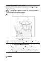
Preparing a Static-Safe Work Station . . . . . . . . . . . . . . . . . . . . .
Power-On Failures . . . . . . . . . . . . . . . . . . . . . . . . . . . . . .
Display Problems . . . . . . . . . . . . . . . . . . . . . . . . . . . . . .
Mainframe Problems . . . . . . . . . . . . . . . . . . . . . . . . . . . . .
Communication Problems on the HP-MSIB I/O . . . . . . . . . . . . . . . . .
Error Messages . . . . . . . . . . . . . . . . . . . . . . . . . . . . . . .
Adjustment Problems . . . . . . . . . . . . . . . . . . . . . . . . . . . .
Verication Test Problems . . . . . . . . . . . . . . . . . . . . . . . . . .
Troubleshooting the A2 RF First Converter . . . . . . . . . . . . . . . . . .
Troubleshooting the A5, A7, A8, A9 Second Converter . . . . . . . . . . . . .
Troubleshooting the A6 Programmable Gain Amplier . . . . . . . . . . . . .
Troubleshooting the A10 Last Converter . . . . . . . . . . . . . . . . . . .
Troubleshooting the A11 5 dB Step Attenuator . . . . . . . . . . . . . . . .
Troubleshooting the A12 RF Switch/A15 RF Switch and A21 Pin Switch/Diplexer
Troubleshooting the A14 YTF and A19 Power Supply/YTF Driver . . . . . . . .
Troubleshooting the A16 Preamp/Mixer . . . . . . . . . . . . . . . . . . . .
Troubleshooting the A18 LO Leveling Amplier . . . . . . . . . . . . . . . .
Troubleshooting the A20 Controller . . . . . . . . . . . . . . . . . . . . . .
Performing Related Adjustments and Verication Tests . . . . . . . . . . . . .
Troubleshooting Utilities Menu . . . . . . . . . . . . . . . . . . . . . . . .
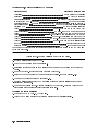
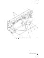
Overall Block Diagram of HP 70909A or HP 70910A RF section . . . . . . . . .
7-2
7-4
7-5
7-9
7-10
7-13
7-17
7-23
7-30
7-31
7-34
7-36
7-38
7-39
7-40
7-43
7-44
7-45
7-47
7-50
7-53
7. Troubleshooting
Contents-2
.
.
.
.
.
.
.
.
.
.
.
.
.
.
.
.
.
.
.
.
.
.
.
.
.
.
.
.
.
.
.
.
.
.
.
.
.
.
.
.
.
.
.
.
.
.
.
.
.
.
.
.
.
.
.
.
.
.
.
.
.
.
.
.
.
.
.
.
.
.
.
.
.
.
.
.
.
.
.
.
.
.
.
.
.
.
.
.
.
.
.
.
.
.
.
.
.
.
.
.
.
.
.
.
.
.
.
.
.
.
.
.
.
.
.
.
.
.
.
.
.
.
.
.
.
.
.
.
.
.
.
.
.
.
.
.
.
.
.
.
.
.
.
.
.
.
.
.
.
.
.
.
.
.
.
.
.
.
.
.
.
.
.
.
.
.
.
.
.
.
.
.
.
.
.
.
.
.
.
.
.
.
.
.
.
.
.
.
.
.
.
.
.
.
.
.
.
.
.
.
.
.
.
.
.
.
.
5-46
8. Replacing Major Assemblies
Module Cover . . . . . . . . . . . . . . . . . . . . . .
Front Panel . . . . . . . . . . . . . . . . . . . . . . .
Rear Panel . . . . . . . . . . . . . . . . . . . . . . .
A2 RF First Converter . . . . . . . . . . . . . . . . . .
A5, A7, A8, A9 Second Converter . . . . . . . . . . . .
A6 Programmable Gain Amplier . . . . . . . . . . . . .
A10 Last Converter . . . . . . . . . . . . . . . . . . .
A11 5 dB Step Attenuator . . . . . . . . . . . . . . . .
A12 RF Switch/A15 RF Switch (HP 70910A RF Section Only)
A14 YTF . . . . . . . . . . . . . . . . . . . . . . . .
A16 Preamp/Mixer . . . . . . . . . . . . . . . . . . . .
A18 LO Leveling Amplier . . . . . . . . . . . . . . . .
A19 Power Supply/YTF Driver Service Position . . . . . .
A19 Power Supply/YTF Driver . . . . . . . . . . . . . .
A20 Controller . . . . . . . . . . . . . . . . . . . . . .
A22 Status . . . . . . . . . . . . . . . . . . . . . . .
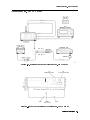
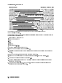
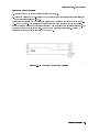
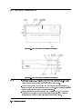
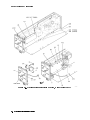
9. Overall Parts Identication Drawings
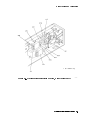
Major Cables and Assemblies . . . . .
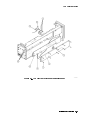
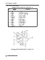
Front View Identication . . . . . . .
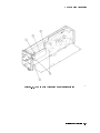
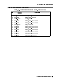
Right Side View Identication . . . .
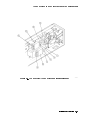
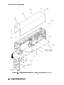
Left Side View Identication, Exploded
Rear View Identication . . . . . . .
.
.
.
.
.
.
.
.
.
.
.
.
.
.
.
.
.
.
.
.
.
.
.
.
.
.
.
.
.
.
.
.
.
.
.
.
.
.
.
.
.
.
.
.
.
.
.
.
.
.
.
.
.
.
.
.
.
.
.
.
.
.
.
.
.
.
.
.
.
.
.
.
.
.
.
.
.
.
.
.
.
.
.
.
.
.
.
.
.
.
.
.
.
.
.
.
.
.
.
.
.
.
.
.
.
.
.
.
.
.
.
.
.
.
.
.
.
.
.
.
.
.
.
.
.
.
.
.
.
.
.
.
.
.
.
.
.
.
.
.
.
.
.
.
.
.
.
.
.
.
.
.
.
.
.
.
.
.
.
.
.
.
.
.
.
.
.
.
.
.
.
.
.
.
.
.
.
.
.
.
.
.
.
.
.
.
.
.
.
.
.
.
.
.
.
.
.
.
.
.
.
.
.
.
.
.
.
.
.
.
8-2
8-4
8-6
8-8
8-10
8-12
8-14
8-16
8-18
8-20
8-22
8-24
8-26
8-28
8-30
8-32
.
.
.
.
.
.
.
.
.
.
.
.
.
.
.
.
.
.
.
.
.
.
.
.
.
.
.
.
.
.
.
.
.
.
.
.
.
.
.
.
.
.
.
.
.
.
.
.
.
.
9-2
9-8
9-9
9-14
9-16
Index
Contents-3
Figures
1-1.
3-1.
4-1.
4-2.
4-3.
4-4.
5-1.
5-2.
5-3.
5-4.
5-5.
5-6.
5-7.
5-8.
5-9.
5-10.
5-11.
5-12.
5-13.
5-14.
5-15.
5-16.
5-17.
5-18.
5-19.
5-20.
5-21.
5-22.
5-23.
5-24.
5-25.
5-26.
5-27.
5-28.
5-29.
5-30.
5-31.
5-32.
5-33.
5-34.
5-35.
5-36.
5-37.
5-38.
Typical Serial Number Label . . . . . . . . . . . . . . . . . . . . . . . .
Typical Serial Number Label . . . . . . . . . . . . . . . . . . . . . . . .
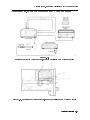
Spectrum Analyzer Calibration Setup . . . . . . . . . . . . . . . . . . . .
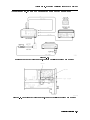
Flatness Calibration and Verication Test Setup . . . . . . . . . . . . . . .
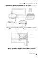
Frequency Reference Connections, Using an HP 70310A Precision Frequency
Reference . . . . . . . . . . . . . . . . . . . . . . . . . . . . . . .
Frequency Reference Connections, Using the HP 8566B Spectrum Analyzer . .
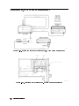
Adjustments Equipment Matrix . . . . . . . . . . . . . . . . . . . . . . .
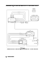
Overall Adjustment Equipment Setup . . . . . . . . . . . . . . . . . . . .
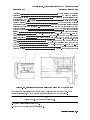
Equipment Setup for Adjustment 01. Power Supply Voltage Checks . . . . . .
Location of A19J8-1 . . . . . . . . . . . . . . . . . . . . . . . . . . . .
Equipment Setup for Adjustment 02. 1st LO Power . . . . . . . . . . . . .
Side View Location of Adjustment 02. 1st LO Power . . . . . . . . . . . . .
PROTECT/ENABLE Switch Location . . . . . . . . . . . . . . . . . . . .
2nd Converter Adjustment Locations . . . . . . . . . . . . . . . . . . . .
2nd Converter Adjustment Locations . . . . . . . . . . . . . . . . . . . .
Equipment Setup for Adjustment 03.01 VCO Tune-Line Voltage . . . . . . . .
Locations for Adjustment 03.01 VCO Tune-Line Voltage . . . . . . . . . . .
Equipment Setup for Adjustment 03.02 VCO Frequency and Amplitude . . . .
Locations for Adjustment 03.02 VCO Frequency and Amplitude . . . . . . . .
Equipment Setup for Adjustment 03.03 2nd Converter LO Feedthrough . . . .
Locations for Adjustment 03.03 2nd Converter LO Feedthrough . . . . . . . .
Equipment Setup for Adjustment 03.04 Sampler DC IF Out . . . . . . . . . .
Locations for Adjustment 03.04 Sampler DC IF Out . . . . . . . . . . . . .
Equipment Setup for Adjustment 03.05 Sampler AC IF Out . . . . . . . . . .
Locations for Adjustment 03.05 Sampler AC IF Out . . . . . . . . . . . . .
Equipment Setup for Adjustment 03.06 Search Oscillator Duty Cycle and Period
Locations for Adjustment 03.06 Search Oscillator Duty Cycle and Period . . .
Equipment Setup for Adjustment 03.07 Search Oscillator Square Wave Min/Max
Locations for Adjustment 03.07 Search Oscillator Square Wave Min/Max . . . .
Equipment Setup for Adjustment 03.08 Search Oscillator VCO Tune Line . . .
Locations for Adjustment 03.08 Search Oscillator VCO Tune Line . . . . . . .
Equipment Setup for Adjustment 03.09 Phase Lock . . . . . . . . . . . . .
Locations for Adjustment 03.09 Phase Lock . . . . . . . . . . . . . . . . .
Equipment Setup for Adjustment 03.10 VCO Tune Range . . . . . . . . . . .
Locations for Adjustment 03.10 VCO Tune Range . . . . . . . . . . . . . .
Equipment Setup for Adjustment 03.11 Lock Range Measurement . . . . . .
Locations for Adjustment 03.11 Lock Range Measurement . . . . . . . . . .
Equipment Setup for Adjustment 03.12 Bandpass Filter and VCO Tune Range
Final . . . . . . . . . . . . . . . . . . . . . . . . . . . . . . . . .
Locations for Bandpass Filter Tune Range and VCO Tune Range . . . . . . .
Equipment Setup for Adjustment 03.13 Mixer Bias . . . . . . . . . . . . . .
Locations for Adjustment 03.13 Mixer Bias . . . . . . . . . . . . . . . . .
Equipment Setup for Adjustment 04. Last Converter Alignment . . . . . . .
Locations for Adjustment 04. Last Converter Alignment . . . . . . . . . . .
Equipment Setup for Adjustment 05. PGA Calibration . . . . . . . . . . . .
Contents-4
1-6
3-3
4-6
4-7
4-10
4-11
5-2
5-4
5-5
5-6
5-7
5-7
5-9
5-10
5-10
5-11
5-11
5-13
5-13
5-15
5-15
5-17
5-17
5-19
5-19
5-21
5-21
5-23
5-23
5-25
5-25
5-27
5-27
5-29
5-29
5-32
5-32
5-34
5-35
5-37
5-37
5-39
5-40
5-44
5-39.
5-40.
6-1.
6-2.
6-3.
6-4.
6-5.
6-6.
6-7.
6-8.
6-9.
6-10.
6-11.
6-12.
6-13.
6-14.
6-15.
6-16.
6-17.
6-18.
6-19.
6-20.
6-21.
6-22.
6-23.
6-24.
7-1.
7-2.
7-3.
7-4.
7-5.
7-6.
8-1.
8-2.
8-3.
8-4.
8-5.
8-6.
8-7.
8-8.
8-9.
8-10.
8-11.
8-12.
8-13.
8-14.
8-15.
8-16.
9-1.
9-2.
9-3.
9-4.
9-5.
9-6.
9-7.
Equipment Setup for Adjustment 06. YTF Alignment . . . . . . . . .
A19 OFFSET (R38) and GAIN (R39) Adjustments . . . . . . . . . . . .
Verication Tests Equipment Matrix . . . . . . . . . . . . . . . . . .
Overall RF Section Verication Test Setup . . . . . . . . . . . . . . .
Equipment Setup for Test 01. Switch Repeatability - HP 70910A Only . .
Equipment Setup for Test 02. External Mixer Gain Calibration Test Setup
Equipment Setup for Test 03. Gain and Flatness Calibration . . . . . .
Equipment Setup for Test 04. Flatness Below 50 MHz . . . . . . . . .
Equipment Setup for Noise Figure Calibration . . . . . . . . . . . . .
Equipment Setup for Gain Calibration and Measurement . . . . . . . .
Equipment Setup for Test 06. External Mixer Noise Figure . . . . . . .
Equipment Setup for Test 07. Microwave TOI . . . . . . . . . . . . .
Equipment Setup for Test 08. Diagnostics Check . . . . . . . . . . . .
Equipment Setup for Test 09. Front Panel LEDs Check . . . . . . . . .
Equipment Setup for Test 10. 21.4 MHz IF Output Response . . . . . .
Equipment Setup for Test 11. IF Emissions and Harmonics . . . . . . .
Equipment Setup for Test 12. EMIM LO Out Power and Harmonics . . .
Equipment Setup for Test 13. 1st LO Out Power and Harmonics . . . .
Equipment Setup for Test 14. TUNE+SPAN+PRESEL PEAK Output . .
Equipment Setup for Test 15. LO Input Amplitude Range . . . . . . .
Equipment Setup for Test 16. Microwave Image Rejection . . . . . . .
Equipment Setup for Test 17. EMIM Image Rejection . . . . . . . . . .
Equipment Setup for Test 18. 2nd Converter Startup . . . . . . . . .
Equipment Setup for Test 19. Microwave Residual Responses . . . . . .
Equipment Setup for Test 20. Microwave In-Range Multiples . . . . . .
Equipment Setup for Test 21. 321.4 MHz IF Output Bandwidth . . . . .
Static-Safe Work Station . . . . . . . . . . . . . . . . . . . . . . .
Line Voltage Selector . . . . . . . . . . . . . . . . . . . . . . . . .
Line Fuse Removal and Replacement . . . . . . . . . . . . . . . . .
display tests Menu Keys . . . . . . . . . . . . . . . . . . . . .
Condence Test . . . . . . . . . . . . . . . . . . . . . . . . . . .
Overall Block Diagram of HP 70909A or HP 70910A RF section . . . . .
Module Cover Removal/Replacement . . . . . . . . . . . . . . . . .
Front Panel Removal/Replacement . . . . . . . . . . . . . . . . . .
Rear Panel Removal/Replacement . . . . . . . . . . . . . . . . . . .
A2 RF First Converter Removal/Replacement . . . . . . . . . . . . .
A5, A7, A8, A9 Second Converter Removal/Replacement . . . . . . . .
A6 Programmable Gain Amplier Removal/Replacement . . . . . . . .
A10 Last Converter Removal/Replacement . . . . . . . . . . . . . .
A11 5 dB Step Attenuator Removal/Replacement . . . . . . . . . . .
A12 RF Switch/A15 RF Switch Removal/Replacement . . . . . . . . .
A14 YTF Removal/Replacement . . . . . . . . . . . . . . . . . . . .
A16 Preamp/Mixer Removal/Replacement . . . . . . . . . . . . . . .
A18 LO Leveling Amplier Removal/Replacement . . . . . . . . . . .
A19 Power Supply/YTF Driver Service Position . . . . . . . . . . . .
A19 Power Supply/YTF Driver Removal/Replacement . . . . . . . . .
A20 Controller Removal/Replacement . . . . . . . . . . . . . . . . .
A22 Status Removal/Replacement . . . . . . . . . . . . . . . . . . .
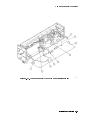
Overall Parts Identication Drawing, Major Cables (1 of 4) . . . . . . .
Overall Parts Identication Drawing, Major Cables (2 of 4) . . . . . . .
Overall Parts Identication Drawing, Major Cables (3 of 4) . . . . . . .
Overall Parts Identication Drawing, Major Cables (4 of 4) . . . . . . .
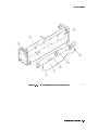
Overall Parts Identication Drawing, Front View . . . . . . . . . . .
Overall Parts Identication Drawing, Right Side View (1 of 4) . . . . . .
Overall Parts Identication Drawing, Right Side View (2 of 4) . . . . . .
NNNNNNNNNNNNNNNNNNNNNNNNNNNNNNNNNNNNNNNNN
.
.
.
.
.
.
.
.
.
.
.
.
.
.
.
.
.
.
.
.
.
.
.
.
.
.
.
.
.
.
.
.
.
.
.
.
.
.
.
.
.
.
.
.
.
.
.
.
.
.
.
.
.
.
.
.
.
.
.
.
.
.
.
.
.
.
.
.
.
.
.
.
.
.
.
.
.
.
.
.
.
.
.
.
.
.
.
.
.
.
.
.
.
.
.
.
.
.
.
.
.
.
.
.
.
.
.
.
.
.
.
.
.
.
.
.
.
.
.
.
.
.
.
.
.
.
.
.
.
.
.
.
.
.
.
.
.
.
.
.
.
.
.
.
.
.
.
.
.
.
.
.
.
.
.
.
.
.
.
.
.
.
.
.
.
5-46
5-48
6-2
6-4
6-5
6-7
6-9
6-11
6-13
6-14
6-17
6-19
6-22
6-24
6-25
6-27
6-29
6-31
6-33
6-35
6-37
6-39
6-41
6-43
6-45
6-47
7-2
7-5
7-5
7-7
7-8
7-53
8-3
8-5
8-7
8-9
8-11
8-13
8-15
8-17
8-19
8-21
8-23
8-25
8-27
8-29
8-31
8-33
9-4
9-5
9-6
9-7
9-8
9-10
9-11
Contents-5
9-8.
9-9.
9-10.
9-11.
Overall Parts Identication Drawing, Right Side View, Exploded (3 of 4)
Overall Parts Identication Drawing, Right Side View, Exploded (4 of 4)
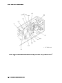
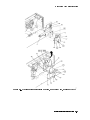
Overall Parts Identication Drawing, Left Side View, Exploded . . . .
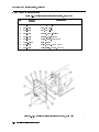
Overall Parts Identication Drawing, Rear View . . . . . . . . . . .
Contents-6
.
.
.
.
.
.
.
.
.
.
.
.
.
.
.
.
9-12
9-13
9-15
9-16
Tables
1-1.
1-2.
7-1.
7-2.
7-3.
9-1.
9-2.
9-3.
9-4.
9-5.
9-6.
HP Service Centers . . . . . . . . . . . . . . . . . . . . . . .
Packaging for a 2/8 Module (RF Section) . . . . . . . . . . . . . .
Static-Safe ESD Accessories . . . . . . . . . . . . . . . . . . .
Default HP-MSIB Address Map . . . . . . . . . . . . . . . . . .
A11 5 dB Step Attenuator Logic . . . . . . . . . . . . . . . . .
Cables for the HP 70909A RF Section and HP 70910A RF Section . .
Assemblies for the HP 70909A RF Section and HP 70910A RF Section
Overall Parts Identication Listing, Front View . . . . . . . . . .
Overall Parts Identication Listing, Right Side View . . . . . . . .
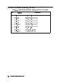
Overall Parts Identication Listing, Left Side View Exploded . . . .
Overall Parts Identication Listing, Rear View . . . . . . . . . . .
.
.
.
.
.
.
.
.
.
.
.
.
.
.
.
.
.
.
.
.
.
.
.
.
.
.
.
.
.
.
.
.
.
.
.
.
.
.
.
.
.
.
.
.
.
.
.
.
.
.
.
.
.
.
.
1-7
1-9
7-3
7-11
7-38
9-2
9-3
9-8
9-9
9-14
9-16
Contents-7
1
Getting Started
Overview
In this chapter you will learn about:
Various types of test software available for your RF section
The organization of this service guide and component-level repair
information
How to contact Hewlett-Packard for servicing or ordering parts
This chapter introduces you to servicing and the various types of test software available for
your RF section. You will rst learn how the service guide and the component-level repair
information (CLIP set) are organized, and then you'll learn how to contact Hewlett-Packard for
servicing or ordering replacement parts.
When is Servicing Needed?
Servicing is needed:
if error messages are displayed on your HP 70000 Series display
if an ERROR LED or FAULT LED is on
or, to perform repairs or adjustments or both
If you determine that your RF section needs servicing, you can return your RF section to
a Hewlett-Packard service center, or you can perform the servicing yourself using module
verication software and the information in this service guide.
To perform the servicing yourself using module verication software, review the rest of the
information in this chapter, and then proceed to Chapter 2 where you will learn how to install
and congure module verication software. To return your RF section to a Hewlett-Packard
service center for service, refer to \Contacting Hewlett-Packard for Servicing or Ordering
Parts".
Overview of Servicing : : : : : : : : : : : : : : : : : : : : : : : : : : : : : : : : : : : : : : : : : : : : : : : : : : : : : : : : : : : : : : : : : : : : : : : : 1-2
Contacting Hewlett-Packard for Servicing or Ordering Parts : : : : : : : : : : : : : : : : : : : : : : : : : : : : : : : : 1-6
Getting Started 1-1
Overview of Servicing
1-2 Getting Started
Overview of Servicing
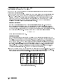
This service guide is part of an Option OB3 package which includes test software and two
manuals.
Test Software
Manual 1
Manual 2
Module Verication Software
HP 70909A/70910A Service Guide
HP 70909A/70910A Component Level Information Package
Types of Test Software Available
There are three categories of test software available, and this service guide documents the use
of module verication tests.
Module Verication Module verication tests are used to test modules so that when
Tests
assembled into a system, the system meets the system's specications.
Module verication tests are used during servicing.
System Verication System verication tests are used to verify the proper operation of
Tests
an instrument and to verify that the instrument meets approximately
80% of its measurement related specications. These sets of tests are
subsets of system performance tests.
System Performance System performance tests are used to verify the proper operation
Tests
of a complete modular measurement system (MMS) to full system
specications.
For information related to system verication tests, refer to the HP 70000 Modular Spectrum
Analyzer Installation and Verication Manual, and for information related to system
performance tests, refer to the documentation for HP 11990A system performance test
software.
Manual 1
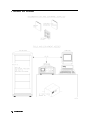
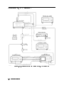
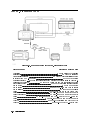
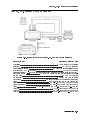
This service guide describes all of the service procedures necessary to troubleshoot, repair,
adjust, and test your RF section. The RF section is a module that is used in HP 70000 Series
modular measurement systems. A standard modular spectrum analyzer system includes a
mainframe with an RF section, IF section, local oscillator, an optional display, and an optional
precision frequency reference.
Chapter 1 \Getting Started"
This chapter introduces you to servicing and the various types of test software available for
your RF section. You will rst learn how the service guide and the component-level repair
information (CLIP set) are organized, and then you'll learn how to contact Hewlett-Packard
for servicing or ordering replacement parts.
Chapter 2 \Installing and Conguring Module Verication Software"
This chapter prepares you to install and congure the module verication software for your
RF section. You then learn how to load module verication software and how to change
conguration settings by editing a TSCRIPT le. Finally, you'll learn how to use the MS_TABLE
program to specify dierent storage locations that CAL FACTOR data les and test results
data can be stored and retrieved from.
Chapter 3 \Running Module Verication Software"
This chapter prepares you to run the module verication tests on your RF section. You
will learn how to load module verication software. Then, you will learn how to change
parameters about your RF section that are used in creating reports. From there, you'll learn
Getting Started 1-3
Overview of Servicing
how to run the module verication software tests, and nally, you'll learn how to create,
edit, print, or purge a CAL FACTOR data le using the Calibration Editor program.
Chapter 4 \Test Equipment and Calibrations"
This chapter contains the test equipment setups for all calibration procedures that must
be performed in order to optimize module performance when assemblies are changed,
repaired, or adjusted. You will learn about the requirements as well as when and how often
calibrations are required. Finally, you'll learn about the requirements for the external
frequency reference being used.
Chapter 5 \Adjustment Procedures"
This chapter contains the test equipment setups for all adjustment procedures that are used
to optimize module performance when assemblies are changed, repaired, or adjusted. All of
the setups described in this chapter are automated and require a controller running module
verication software.
Chapter 6 \Verication Tests"
This chapter contains the test equipment setups for all module verication tests that are
used to optimize module performance when assemblies are changed, repaired, or adjusted.
All of the setups described in this chapter are automated and require a controller running
module verication software.
Chapter 7 \Troubleshooting"
This chapter prepares you for troubleshooting your RF section. You will learn how to prepare
a static-safe work station that is used during servicing. Then, you will learn how to resolve
power-on problems, adjustment problems, and verication test problems. Finally, you'll
learn in-depth circuit troubleshooting as well as which adjustments and verication tests
have to be run to ensure proper operation after an assembly has been repaired, replaced, or
adjusted.
Chapter 8 \Replacing Major Assemblies"
This chapter contains procedures for removal and replacement of major assemblies in your
RF section.
Chapter 9 \Overall Parts Identication Drawings"
This chapter contains information on all overall parts identication drawings that should be
used when performing the troubleshooting procedures described in this service guide.
Index
An index is also added at the end of this service guide to aid the user in nding key items of
interest.
Manual 2
Manual 2 is a separate volume that contains packets of component-level repair information
for each RF section board assembly that has eld-replaceable parts. Each packet includes the
parts list, component-location drawing, and schematics for a specic board-assembly part
number. Manual 2 also contains a table that can be used to cross reference dierent board
assemblies that have dierent serial prex breaks.
1-4 Getting Started
Overview of Servicing
Information Not Covered in Manual 1 or 2
System congurations are documented in the HP 70000 Modular Spectrum Analyzer
Installation and Verication Manual and HP 71910P Wide-Bandwidth Receiver User's
Guide.
Error codes not covered in the troubleshooting chapter of this manual (Chapter 7) may be
found in the HP 70000 Modular Spectrum Analyzer Installation and Verication Manual,
HP 71910P Wide-Bandwidth Receiver User's Guide, and additional module specic service
guides.
Each modular measurement system (MMS) module has its own service guide. For further
information related to the servicing of additional and alternate modules that can be used in
this system, refer to each module's service guide.
Before You Begin Servicing
Review the Troubleshooting sections of Chapter 7 as well as the directions for \Installing and
Conguring Test and Adjustment Software" in Chapter 2.
Getting Started 1-5
Contacting Hewlett-Packard for Servicing or Ordering Parts
Contact Hewlett-Packard for service or ordering parts.
Service
Before calling Hewlett-Packard or returning your RF section for service, please
read your warranty information. Warranty information is printed at the front
of this service guide.
Ordering Parts To order parts, contact the HP Service Center closest to you.
In any correspondence or telephone conversations, refer to the RF section by its full model
number and full serial number. With this information, the Hewlett-Packard representative can
determine whether your unit is still within its warranty period.
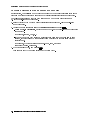
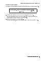
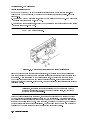
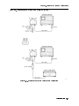
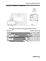
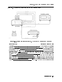
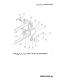
Determining Your RF Section's Serial Number
When a module is manufactured by Hewlett-Packard, it is given a unique serial number. This
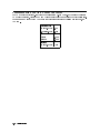
serial number is attached to a label on the front frame or front panel of the module. A serial
number label is in two parts. (Refer to Figure 1-1.) The rst part makes up the serial number
prex and consists of four digits and a letter. The second part makes up the serial number
sux and consists of the last ve digits on the serial number label. The serial number prex is
the same for all identical modules; it only changes when a change in the electrical or physical
functionality is made. The serial number sux, however, changes sequentially and is dierent
for each module.
Figure 1-1. Typical Serial Number Label
1-6 Getting Started
Contacting Hewlett-Packard for Servicing or Ordering Parts
A current list of Hewlett-Packard Service Centers can be accessed on the Internet at:
http://www.tmo.hp.com/tmo/contacts/
If you do not have access to the Internet, one of the following Hewlett-Packard locations can
direct you to your nearest Hewlett-Packard representative:
Table 1-1. HP Service Centers
United States
Canada
Europe
Japan
Latin America
Austrailia/New
Zealand
Asia-Pacic
Hewlett-Packard Company
Test and Measurement Call Center
(800) 403-0801
(800) 857-8161 (FAX)
Hewlett-Packard Canada Ltd.
5150 Spectrum Way
Mississauga, Ontario L4W 5G1
(905) 206-4725
(905) 206-4739 (FAX)
Hewlett-Packard European Marketing Centre
Postbox 667
1180 AR Arnstelveen
Netherlands
(31/20) 547-6669
(31/20) 647-8706
Hewlett-Packard Japan Ltd.
27-15, Yabe 1-Chome,
Sagamihara, Kanagawa 229
Japan
(81426) 567 832
(81426) 567 843 (FAX)
Hewlett-Packard Latin America Region Headquarters
5200 Blue Lagoon Drive, 9th Floor
Miami, Florida 33126
U.S.A.
(305) 267 4245
(305) 267 4288 (FAX)
Hewlett-Packard Calibration Services Austrailia Ltd.
31-41 Joseph Street
Blackburn, Victoria 3130
Austrailia
1800 802 540
1800 681 776 (FAX)
Hewlett-Packard Asia-Pacic Ltd.
17-21/F Shell Tower, Times Square
1 Matheson Street, Causeway Bay
Hong Kong
(852) 25 997 777
(852) 25 069 261 (FAX)
Getting Started 1-7
Contacting Hewlett-Packard for Servicing or Ordering Parts
Returning Your RF Section for Service
Hewlett-Packard has sales and service oces around the world to provide complete support for
your RF section. To obtain servicing information or to order replacement parts, contact the
nearest Hewlett-Packard sales and service oce listed in Table 1-1.
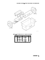
Use the following procedure to return your RF section to Hewlett-Packard for service:
1. Fill out a service tag (available at the end of this service guide) and attach it to the
instrument. Please be as specic as possible about the nature of the problem. Send a copy
of any or all of the following information:
any error messages that appeared on the HP 70000 Series display
a completed Performance Test record
any other specic data on the performance of the RF section
CAUTION
Damage can result if the original packaging materials are not used. Packaging
materials should be anti-static and should cushion the RF section on all sides.
Never use styrene pellets in any shape as packaging materials. They do not
adequately cushion the instrument or prevent it from moving in the shipping
container. Styrene pellets can also cause equipment damage by generating
static electricity or by lodging in fan motors.
2. Place the RF section in its original packaging materials.
If the original packaging materials are not available, you can contact a Hewlett-Packard
sales and service oce to obtain information on packaging materials or you may use an
alternative packing material referred to as \bubble-pack". One of the companies that makes
bubble-pack is Sealed Air Corporation of Hayward, California, 94545.
3. Surround the RF section with at least 3 to 4 inches of its original packing material or
bubble-pack to prevent the RF section from moving in its shipping container.
4. Place the RF section, after wrapping it with packing material, in its original shipping
container or a strong shipping container that is made of double-walled corrugated cardboard
with 159 kg (350 lb) bursting strength.
The shipping container must be both large enough and strong enough to accommodate your
RF section and allow at least 3 to 4 inches on all sides for packing material.
5. Seal the shipping container securely with strong nylon adhesive tape.
6. Mark the shipping container \FRAGILE, HANDLE WITH CARE" to help ensure careful
handling.
7. Retain copies of all shipping papers.
1-8 Getting Started
Contacting Hewlett-Packard for Servicing or Ordering Parts
Table 1-2. Packaging for a 2/8 Module (RF Section)
Item Description HP Part Number Qty
1
2
3
4
5
Carton-outer
Carton-inner
Carton-sliders
Foam inserts
Foam pads
5180-8479
9211-4781
5180-2369
4208-0493
5180-8469
1
1
1
1
2
Getting Started 1-9
Installing and Conguring
Module Verication Software
Overview
2
In this chapter you will learn about:
Computer software and hardware requirements
Keyboard compatibility
Installing module verication software, TSCRIPT, and MS TABLE
Purging module verication software, TSCRIPT, and MS TABLE
Test equipment requirements including default models and HP-IB addresses
Editing the TSCRIPT le
Specifying storage locations for CAL FACTOR data les and test result data
This chapter prepares you to install and congure the module verication software for your
RF section. You then learn how to load module verication software and how to change
conguration settings by editing a TSCRIPT le. Finally, you'll learn how to use the MS_TABLE
program to specify dierent storage locations where CAL FACTOR data les and test results
data can be stored and retrieved from.
Computer Software Requirements : : : : : : : : : : : : : : : : : : : : : : : : : : : : : : : : : : : : : : : : : : : : : : : : : : : : : : : : : : : : 2-2
Computer Hardware Requirements : : : : : : : : : : : : : : : : : : : : : : : : : : : : : : : : : : : : : : : : : : : : : : : : : : : : : : : : : : : 2-3
Installing Software and Creating Working Copies : : : : : : : : : : : : : : : : : : : : : : : : : : : : : : : : : : : : : : : : : : : : 2-5
Conguring Module Verication Software : : : : : : : : : : : : : : : : : : : : : : : : : : : : : : : : : : : : : : : : : : : : : : : : : : : 2-11
Working with the TSCRIPT File : : : : : : : : : : : : : : : : : : : : : : : : : : : : : : : : : : : : : : : : : : : : : : : : : : : : : : : : : : : : : 2-16
Working with the MS_TABLE Data File : : : : : : : : : : : : : : : : : : : : : : : : : : : : : : : : : : : : : : : : : : : : : : : : : : : : : : 2-23
Installing and Conguring Module Verication Software
2-1
Computer Software Requirements
To run the module verication software, your computer system must have the following
components:
HP BASIC 6.3 or above and the appropriate binary les loaded in the computer. If necessary,
refer to an HP BASIC reference manual.
CLOCK
CRTA
CRTB
CRTX
CS80
DCOMM3
DISC
EDIT
ERR
GRAPH
GRAPHX
HFS2
HPIB
IO
KBD
MAT
MS
PDEV1
SRM3
XREF1
Optional: Required only for DEBUG.
2 Optional: Required only for HFS (hierarchical le system) environment.
3 Optional: Required only for SRM (shared resource management) environment.
1
2-2 Installing and Conguring Module Verication Software
Computer Hardware Requirements
Computer Hardware Requirements
To run the module verication software, your computer system must have the following:
Computer
HP 9000 Series 300 controller
HP BASIC
HP BASIC 6.3 or above and the appropriate binary les loaded
RAM
8 MB of RAM
Interface
One HP-IB interface
Hard Disk
SRM or HFS hard disk with 5 MB available space
Floppy Disk
Dual or single 3.5 inch double-sided double-density 720 KB oppy disk drives
Computer Keyboard Compatibility and Mouse Operation
The instructions in this service guide are based on an HP 9000 Series 300 controller with an
HP 46021A keyboard. The module verication software supports several input devices; it will
detect the keyboard you are using and will display the appropriate key commands. However,
keystrokes and text dierences may appear in the softkeys and menus displayed on screen. If
you are using an HP 98203C keyboard, refer to the section \Using an HP 98203C Keyboard
with a Series 300 Computer".
Using an HP 46021A Keyboard with a Series 300 Computer
If you use an HP 46021A keyboard (ITF keyboard) with a Series 300 computer, the module
verication software assumes you have a mouse or a track ball.
To highlight your preference, press the 485 or 495 keys.
To choose the highlighted item, press 4Select5. To save your choice and return to the menu,
press 4Return5.
To exit the menu, press 45.
Installing and Conguring Module Verication Software
2-3
Computer Hardware Requirements
Using an HP 98203C Keyboard with a Series 300 Computer
If you use an HP 98203C (Nimitz) keyboard, the equivalent keys are:
HP 46021A Keyboard HP 98203C Keyboard
45
(home)
4Delete
4Enter5
line5
4DEL
LN5
4Return5
4Enter5
4Select5
4Enter5
4Stop5
4Menu5
or 4Continue5
4Pause5
NNNNNNNNNNNNNNNNNNNNNNNNNN
Continue
4Continue5
To highlight an item in the menu, use 485 and 495, or turn the keyboard knob.
To choose the highlighted item, press 4ENTER5.
NNNNNNNNNNNNNN
NNNNNNNNNNNNNN
To exit the menu, highlight QUIT or EXIT , and press 4Return5.
NNNNNNNNNNNNNN
NNNNNNNNNNNNNN
If neither QUIT nor EXIT is displayed, press 4Continue5 to exit.
Using a Mouse with a Series 300 Computer
The module verication software displays the choices available in each menu screen.
Slide the mouse up or down to highlight your preference.
To choose the highlighted item, press the left-hand button on the mouse or slide the mouse to
the right.
NNNNNNNNNNNNNN
NNNNNNNNNNNNNN
NNNNNNNNNNNNNN
To exit the menu, press QUIT or EXIT if they are displayed in a menu. If neither QUIT nor
EXIT is displayed, slide the mouse to the left to exit.
NNNNNNNNNNNNNN
2-4 Installing and Conguring Module Verication Software
Installing Software and Creating Working Copies
Installing Software and Creating Working Copies
Overview
In this section you will perform the following steps:
Run INSTALL, from a oppy disk drive or other logical device, and create a
working copy.
The INSTALL program performs the following:
a. Assigns a source disk drive (and optional directory)
b. Assigns a destination disk drive (and optional directory)
c. Copies source les to the destination disk drive (and optional directory)
Module verication software for the RF section consists of the following les:
Executive Disk 1
OPV
CSUBS
CSUBS6
CSUBS63_UX
CSUBS64_UX
CSUBS7_UX
INSTALL
COM
UT_SUBS1
CAL_EDIT
READ_ME
DATA_SHEET
Disk_1
Executive Disk 2
UT_SUBS
D_8757
UT_SUBS0
D_3456
TSCRIPT
D_3457
TSCRIPT.MS
D_436
TESTINFO
D_438
OPTIONS
D_8970
MUT_INFO
D_8566
ADDR_DEFS
D_71200
MUT_LIST
D_3335
UNCERTS
D_8662
C_TSCRIPT
D_8340
NET_ANAL
D_836x
DVM
Disk_2
ET
PWR_MTR
RCVR
SOURCE
SPEC_ANAL
Tests
DIAGNOSTIC
EM_IMGRJT
FLAT_50MH
LED_CHECK
MW_MULT
MWNOISEFIG
MW_RESID
MW_TOI
NIFO_RESP
TUNE_SPAN
SW_REPEAT
WIFO_300
EMNOISEFIG
PWR_HARM
PWR_HARM_
AMP_RANGE
FLATNESS
SYS_CAL
Disk
MW_IMGRJT
EMGAINCAL
AMP_ADJUST
LAST_CONV
PGA_CALIB
2ND_CONV
PS_CHECK
SEC_STUP
YTF_ALIGN
WIDE_IFO
WBFE_UTIL
TEST_SUBS
REPT_SUBS
MS_TABLE
MS_TAB.MS
EDIT_MSTAB
Disk_3
Installing and Conguring Module Verication Software
2-5
Installing Software and Creating Working Copies
To create a working copy on an SRM or HFS hard disk
In this section, you will learn how to create a working copy of module verication software on
either an SRM (shared resource manager) or HFS (hierarchical le structure) hard disk drive.
The following steps assume that you have either an SRM or HFS hard disk system and a
3.5 inch double-sided oppy disk drive.
1. Insert Executive Disk 1 of the module verication software into a 3.5 inch double-sided
oppy disk drive.
2. Assign the MSI (mass storage is:) of the source disk drive and press 4Return5.
During a rst-time installation, enter the MSI of the 3.5 inch double-sided oppy disk drive
used in step 1.
(For example, MSI ":,700,0".)
If you have a backup copy stored on a dierent disk drive that you would like to load
instead, enter the full MSVS (mass storage volume specier) of the disk along with any
directory path.
(For example, type MSI "/OPV9000/70909A_10A:,1400,0" or MSI
"/OPV9000/70909A_10A:HFS".)
3. Type LOAD "INSTALL",1 and press 4Return5.
This runs the INSTALL program located on Executive Disk 1.
2-6 Installing and Conguring Module Verication Software
Installing Software and Creating Working Copies
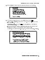
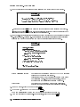
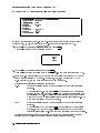
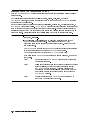
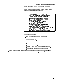
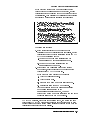
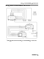
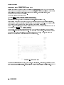
4. Read the installation overview screen that appears and press any key to continue.
d
INSTALLATION OVERVIEW
=====================
a
HP 70909A/70910A Module Verification Software
must be installed on an SRM or HFS hard disk.
This installation creates a working copy. After
installation, store the original disks in a safe
place; they will only be needed in the event that
the working copy becomes corrupt or damaged. If
desired, backup copies can be created for archiving.
c
Press any key to continue...
b
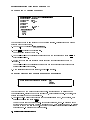
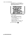
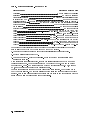
5. At the program prompt, enter the MSVS of the source les and press 4Return5.
During a rst-time installation, enter the MSVS of the 3.5 inch double-sided oppy disk
drive used in step 1.
(For example, :,700,0. If you press 4Return5, the default source MSVS is set using the
value of the current MSI.)
If you have a backup copy stored on a dierent disk drive that you would like to load
instead, enter the full MSVS of the disk along with any directory path.
(For example, type "/OPV9000/70909A_10A:,1400,0" or "/OPV9000/70909A_10A:HFS".)
d
INSTALLING FILES ONTO AN SRM or HFS HARD DISK
=============================================
a
HFS systems require that you enter the volume specifier and a path.
(For example, /OPV9000/70909A_10A:,1400,0 or /OPV9000/70909A_10A:HFS.)
SRM systems require that you enter the SRM select code and the node
address (for example, :,21,0 for an SRM system with a select code of 21
and a node address of 0). If a path is used, it must also be included.
(For example, /OPV9000/70909A_10A:,21,0 or /OPV9000/70909A_10A:REMOTE.)
1.
c
Press the Return key to accept the default MSVS specified,
or Enter the MSVS of the source files and press Return:
...Default source MSVS: (A default source MSVS is displayed.)
b
Installing and Conguring Module Verication Software
2-7
Installing Software and Creating Working Copies
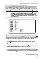
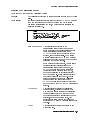
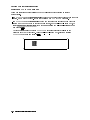
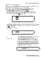
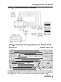
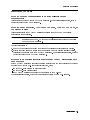
6. At the program prompt, enter the MSVS, with an optional-directory path, of where the
module verication software is to be installed and press 4Return5; this sets the destination
HFS/SRM directory path.
Press 4Return5 to accept /OPV9000/70909A_10A/ as the default destination HFS/SRM
directory path.
If you want the module verication software installed in a dierent directory, substitute a
dierent destination HFS/SRM directory path and press 4Return5.
d
INSTALLING FILES ONTO AN SRM or HFS HARD DISK
=============================================
a
HFS systems require that you enter the volume specifier and a path.
(For example, /OPV9000/70909A_10A:,1400,0 or /OPV9000/70909A_10A:HFS.)
SRM systems require that you enter the SRM select code and the node
address (for example, :,21,0 for an SRM system with a select code of 21
and a node address of 0). If a path is used, it must also be included.
(For example, /OPV9000/70909A_10A:,21,0 or /OPV9000/70909A_10A:REMOTE.)
1. Press the Return key to accept the default MSVS specified,
or Enter the MSVS of the source files and press Return:
Source MSVS: (A default source MSVS is displayed.)
2. Press the Return key to accept the default MSVS specified,
or Enter the MSVS of the destination path and press Return:
c
Tip
...Default destination MSVS: (A default destination MSVS is displayed.)
b
You can determine a complete directory path with the following steps:
a. Press 4Stop5 to exit the module verication software.
b. Assign the MSI (mass storage is:) of the SRM or HFS disk drive without
including a directory path and press 4Return5.
(For example, type MSI ":,1400,0" or MSI ":HFS".)
c. Type CAT at the HP BASIC command prompt and look at the directory path
that is displayed at the top of the listing.
If the top of the listing is not visible (due to a large number of les in the
current directory that cause the display to scroll up out of view), you can
either press the 4Prev5 button to view the top of the listing, or press 4Break5
before the top of the listing is scrolled out of view. In either case, you might
wish to write down the directory path so that you can enter it at the prompt
when needed.
d. Repeat this procedure, \Loading software les onto an HFS hard disk", from
the beginning.
2-8 Installing and Conguring Module Verication Software
Installing Software and Creating Working Copies
NNNNNNNNNNNNNNNNNNNNNNNNNN
7. When prompted, remove Executive Disk 1, insert Executive Disk 2, and press Continue .
NNNNNNNNNNNNNNNNNNNNNNNNNN
If you have an HP 46021A keyboard, and the Continue softkey does not appear on the
display, press 4Menu5. If you are using an HP 98203C keyboard, refer to the section \Using an
HP 98203C Keyboard with a Series 300 Computer".
8. When prompted, remove Executive Disk 2, insert the Tests Disk, and press Continue .
NNNNNNNNNNNNNNNNNNNNNNNNNN
COPY COMPLETED is displayed when all les have successfully been copied.
Installing and Conguring Module Verication Software
2-9
Installing Software and Creating Working Copies
To purge a copy of module verication software
CAUTION
If the directory being purged contains les that you wish to retain, move
(relocate) the les to a dierent directory before performing this procedure.
Note
In order to purge both les and a directory, your current MSI can not be set to
the directory that you are purging.
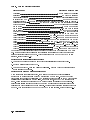
If you are using HP BASIC 6.3 through HP BASIC 6.4:
1. Type, WILDCARDS UX; ESCAPE "\"
2. Type, PURGE "/OPV9000/[directory path]/*"
You should get a prompt similar to the following (where xx is number of les):
d
c
Purge xx files?
(Press <Cont> to proceed, <Stop>/<Pause> to cancel.)
3. To purge the les, press 4Continue5.
This removes all of the les in the directory.
4. Type, PURGE "/OPV9000/[directory path]"
This removes the directory itself.
5. Type, WILDCARDS OFF
2-10 Installing and Conguring Module Verication Software
a
b
Conguring Module Verication Software
Conguring Module Verication Software
Before running module verication software, it should be congured to work with the test
equipment and le system that you are using.
Overview
How to proceed:
1. Congure the test equipment settings by editing the TSCRIPT le.
When editing the TSCRIPT le, refer to the \Test Equipment Requirements".
2. Run the EDIT_MSTAB program and specify the storage locations of
CAL FACTOR data les and test results. The EDIT_MSTAB program modies
entries in the MS_TABLE data le.
3. Load module verication software and enter information about your
RF section (UUT).
4. Specify whether test reports are to be directed to the printer or the display.
5. Run module verication software from the main menu.
If you are required to use a power sensor in an adjustment or verication
test, use the Calibration Editor program to create, edit, print, or purge
CAL FACTOR data les, or change the directory path (MSVS) of where
CAL FACTOR data les are located in your le system.
Connecting test equipment HP-IB interface cables : : : : : : : : : : : : : : : : : : : : : : : : : : : : : : : : : : : : : : : : : 2-15
Working with the TSCRIPT File : : : : : : : : : : : : : : : : : : : : : : : : : : : : : : : : : : : : : : : : : : : : : : : : : : : : : : : : : : : : : 2-16
Working with the MS_TABLE Data File : : : : : : : : : : : : : : : : : : : : : : : : : : : : : : : : : : : : : : : : : : : : : : : : : : : : : : 2-23
Installing and Conguring Module Verication Software
2-11
Conguring Module Verication Software
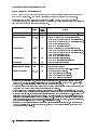
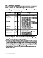
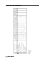
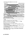
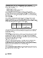
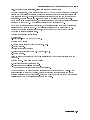
Test Equipment Requirements
The HP 70909A/70910A module verication software only contains drivers for the equipment
shown in the table below. The equipment is listed in order of preferred model number.
In all cases, the specied aging rate requirement is 1009 ms/day. The microwave source,
synthesized source, and calibrated spectrum analyzer listed in the following table have internal
time bases that meet the aging rate requirement.
Equipment
Controller
Signal Sources
Full microwave source
Microwave source
TSCRIPT
Label
Default
HP-IB
Address
NONE
SYN12 , 3 , 4
SYN2 2
,4
727
715
Synthesized source
SYN3
725
Level generator
LG1
704
Calibrated spectrum analyzer
SA1
728
Analyzers
Scalar network analyzer
NA12
, 3 ,4
726
Recommended
Model
HP 9000 Series 300 controller (SELECT CODE 7 or 8.)1
HP 83630A/B Option 001 and 008 synthesized sweeper,
or HP 83640A/B Option 001 and 008 synthesized sweeper,
or HP 83650A/B Option 001 and 008 synthesized sweeper,
or HP 8340B synthesized sweeper,
or HP 8340A synthesized sweeper
HP 83630A/B Option 001 and 008 synthesized sweeper,
or HP 83640A/B Option 001 and 008 synthesized sweeper,
or HP 83650A/B Option 001 and 008 synthesized sweeper,
or HP 8340B synthesized sweeper,
or HP 8340A synthesized sweeper
HP 8662A synthesized signal generator,
or HP 8663A synthesized signal generator
HP 3335A synthesizer/level generator
HP 8566B spectrum analyzer
(upgraded with rmware version 16.7.85 or later)
HP 8757D scalar network analyzer,
or HP 8757C scalar network analyzer,
or HP 8757B scalar network analyzer,
or HP 8757A scalar network analyzer
To determine the proper select code, refer to \Connecting test equipment HP-IB interface cables" in Chapter 2. If
SELECT CODE 8 is used, all default addresses listed in the above table should be set with an 8xx HP-IB address, as
opposed to 7xx. TSCRIPT addresses must also be updated to reect these changes.
2 The dierence between the full microwave source and the microwave source is that the full microwave source is the
combination of a microwave source coupled with a scalar network analyzer.
3 To communicate with the full microwave source, when being used with a scalar network analyzer, HP-IB commands
must be passed through the scalar network analyzer's system interface bus (private bus) to the full microwave source.
In order to accomplish this, the scalar network analyzer's (internal) SWEEPER address and the HP-IB address of the
full microwave source must be set to the same address. When using this version of module verication software, the
scalar network analyzer's (internal) SWEEPER address and the HP-IB address of the full microwave source must both
be set to 19; this is hard-coded in the module verication software and can not be changed. (For further information,
refer to the section \To specify SWEEPER and HP-IB addresses" in Chapter 2.)
4 If using an HP 8360 Series synthesized sweeper for SYN1 or SYN2 (as designated in TSCRIPT ), it must be placed in
HP 8340 Compatibility Mode. (Refer to the procedure, \To set the HP 8360 Series Synthesized Sweeper to HP 8340
Compatibility Mode" in Chapter 2.)
1
2-12 Installing and Conguring Module Verication Software
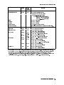
Conguring Module Verication Software
Equipment
TSCRIPT
Label
Default
HP-IB
Address
SYN4
718
Noise source
Noise gure meter
NSRC
NMTR1
NONE
708
Power meter
PM11 , 2
MWPS
LPPS
713
713,0,0
712
713,0,1
NONE
NONE
LFPS
NONE
DVM
722
HP 70000 Components
Local oscillator source
Display
Mainframe
IF section
Module Extender
Frequency reference
Meters
PM21
Power sensor
Precision DVM
,2
Recommended
Model
HP 70900B local oscillator source
(upgraded with rmware version
911021 [V.U.F. B.04.01] or later)
or HP 70900A local oscillator source
(upgraded with rmware version
911021 [V.U.F. B.04.01] or later)
HP 70004A color display
HP 70001A mainframe
HP 70902A IF section
HP 70001-60013 extender module
Refer to \External Frequency Reference Requirements" in
Chapter 4.
HP 346C broadband noise source
HP 8970B noise gure meter,
or HP 8970A noise gure meter
HP 436A power meter (2 required),
or HP 438A dual-channel power meter
HP 436A power meter (2 required),
or HP 438A dual-channel power meter
HP 8485A APC-3.5 mm(m) power sensor
HP 8481D N(m) power sensor,
or HP 8484A N(m) power sensor,
or HP 8485D APC-3.5 mm(m) power sensor
HP 8482A N(m) power sensor,
or HP 8481A N(m) power sensor
HP 3456A digital multimeter,
or HP 3457A digital multimeter
When using an HP 436A power meter, the ADDRESS TYPE must be specied as HP-IB (as designated in TSCRIPT).
2 When using an HP 438A dual-channel power meter, the ADDRESS TYPE must be specied as OTHER (as designated
in TSCRIPT). The format that is used on the HP-IB address consists of three numbers separated by commas
(713,0,0). The rst number designates HP-IB address 713, followed by 0, followed by a 0 (selecting channel A) or a
1 (selecting channel B). For example, 713,0,0 designates channel A while 713,0,1 designates channel B.
1
Installing and Conguring Module Verication Software
2-13
Conguring Module Verication Software
Ampliers
HP 83006A microwave amplier
HP 8447A RF amplier,
or HP 8447D RF amplier,
or HP 8447E RF amplier,
or HP 8447F RF amplier
Standard Equipment
HP 8493C Option 006 coaxial xed attenuator
HP 8493C Option 010 coaxial xed attenuator
HP 11667B power splitter
HP 909D Option 011 50
3.5 mm(f) termination
HP 11636B power divider/combiner
HP 85025B detector (2 required),
or HP 85025E detector (2 required)
Accessory Equipment
HP 0955-0204 microwave isolator
HP 87421A power supply
Cables
HP 8120-1840 122 cm 50
coaxial BNC(m) to BNC(m) (6 required)
HP 8120-5022 365 mm SMB(f) to SMB(f) (5 required)
HP 5061-9038 520 mm SMA(m) to SMA(m)
HP 8120-4921 91 cm 50
APC-3.5 mm(m) to APC-3.5 mm(m) (3 required)
HP 85680-60093 123 cm 50
BNC(m) to SMB(f) (2 required)
Adapters
HP 1251-2277
HP 1250-1236
HP 1250-0674
HP 1250-1158
HP 1250-1292
HP 1250-0672
HP 1250-1159
HP 5061-5311
HP 1250-1748
HP 1250-1750
HP 1250-1744
50
BNC(f) to dual banana plug
50
SMB(f) to BNC(f)
50
SMB(m) to SMA(f)
50
SMA(f) to SMA(f) (2 required)
50
BNC(f) to alligator clips
50
SMB(f) to SMB(f)
50
SMA(m) to SMA(m) (2 required)
50
APC-3.5(f) to APC-3.5(f) (2 required)
50
APC-3.5(m) to APC-3.5(m) (2 required)
50
APC-3.5(m) to N(f)
50
APC-3.5(f) to N(m) (2 required)
HP 70000 system service kit HP 71000-600021
HP 70001-60013 extender module
HP 70001-00038 right modied mainframe cover
HP 70001-00039 left modied mainframe cover
HP 5021-6773 cable puller
HP 8710-1651 short 8 mm hex-ball driver2
HP 8710-1728 bandpass lter tuning tool2
HP 85680-60093 123 cm 50
BNC(m) to SMB(f) (three)2
HP 5061-9021 390 mm SMB(f) to SMB(f) (seven)
HP 8160-0495 chromeric gasket (two feet)
HP 5021-7445 connector pin straightener
Accessory Service Tools
HP 8710-0033 nonmetallic tuning tool
HP 8710-1791 ceramic adjustment tool
HP 08555-20097 5/16 inch modied box wrench
This kit includes servicing tools used to repair all HP 70000A modular spectrum analyzer modules, and
a modication procedure for the HP 70001A mainframe which allows access to modules during bench
testing and repair. This kit does not cover all MMS products.
2 This part is required during servicing for the HP 70909A or HP 70910A RF section.
1
2-14 Installing and Conguring Module Verication Software
Conguring Module Verication Software
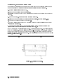
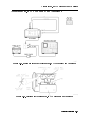
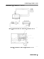
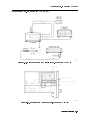
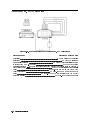
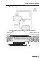
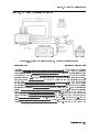
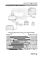
Connecting Test Equipment HP-IB Interface Cables
1. Connect the HP-IB interface to the computer port.
If the computer has an HP 98624A HP-IB interface:
a. Connect the HP-IB interface to the port labeled HP-IB SELECT CODE 8.
b. Check that the address switch on the HP 98624A HP-IB interface matches the HP-IB
controller device address.
c. If necessary, refer to HP 9000 Series 200/300 Peripheral Installation Guide, Volume I.
If the computer has an HP-IB interface other than an HP 98624A HP-IB interface:
a. Connect the HP-IB interface to the port labeled HP-IB SELECT CODE 7.
b. Check that the address switch on the HP-IB interface matches the HP-IB controller
device address.
c. If necessary, refer to HP 9000 Series 200/300 Peripheral Installation Guide, Volume I.
2. Connect the HP-IB cables from the test equipment to the computer's HP-IB SELECT CODE 7
port.
3. If you are using an external disk drive, connect its HP-IB to the HP-IB SELECT CODE 7 port
on the computer, using a 0.5 meter HP-IB cable (HP 10833D, or a similar cable).
Occasionally disk drives exhibit unpredictable behavior when sharing the HP-IB with
instruments. If this happens, connect the external disk drive to a separate HP-IB interface.
4. Set the external test equipment and the mainframe line switches to on. Allow the
equipment to warm up as specied for the module verication software tests.
5. Turn on the computer (and the external disk drive).
6. If you are using an HP-IB printer, connect its HP-IB cable.
The HP-IB printer must be set to address 01 and can only be used with select code 7. This
means that an HP-IB printer can only be used when it is set to HP-IB address 701; module
verication software will not recognize an HP-IB printer at any other address.
Installing and Conguring Module Verication Software
2-15
Working with the TSCRIPT File
Overview
In this procedure, you will perform the following steps:
a. Create a backup copy of the TSCRIPT le before making changes.
b. Load and edit the TSCRIPT le so that it matches your test equipment model
numbers and HP-IB addresses.
c. Save the edited version of the TSCRIPT le.
d. Run the C_TSCRIPT program which creates a new TESTINFO BDAT le.
The TSCRIPT le contains the model numbers and HP-IB addresses of the test equipment and
the test accessories required for each module verication software test.
Before module verication software runs any tests, equipment requirements are compiled
into a list that is stored in the TESTINFO BDAT le. The TESTINFO BDAT le is created when
the C_TSCRIPT program is run. C_TSCRIPT uses the TSCRIPT le as its information source.
TSCRIPT is the le that you may need to edit to match both your equipment model numbers
and HP-IB addresses. If your actual test equipment does not match both the model numbers
and HP-IB addresses that are displayed and you continue, an error may occur.
If an error occurs, you can do one of the following:
edit the TSCRIPT le to match both the HP-IB addresses and model numbers of your test
equipment, and run the C_TSCRIPT program to create a new TESTINFO BDAT le
This is the only way to match the TSCRIPT le to the model numbers of your test equipment.
physically change the HP-IB addresses of your test equipment to match the displayed list
use EDIT mode to temporarily edit the HP-IB addresses of the test equipment being used
Note
If a cursor is not visible on your display, type the following command at the
HP BASIC prompt and press 4Return5: control 1,10;1
2-16 Installing and Conguring Module Verication Software
Working with the TSCRIPT File
To create a backup copy of the TSCRIPT le
Using HP BASIC, create a copy of the TSCRIPT le.
For example:
1. Set the MSI to the MSVS of the disk drive that contains your working copy of module
verication software.
(For example, MSI "/OPV9000/70909A_10A:,1400,0" or MSI "/OPV9000/70909A_10A:HFS".)
2. Type, COPY "TSCRIPT" TO "TSCRIPT_BK"
If ERROR 54 Duplicate file name is displayed, the TSCRIPT le has been previously backed
up.
At this point, you can either:
remove the previous backed-up le and then type COPY "TSCRIPT" TO "TSCRIPT_BK"
or, change the name of the backup le that is being created by typing
COPY "TSCRIPT" TO "TSCRIPT_BK2".
The time stamp on each le will show when each backup was created. To see the time
stamps of all lenames that start with TS, type cat;select "TS".
To load and edit the TSCRIPT le
3. Type GET "TSCRIPT" and press 4Return5.
Wait for the asterisk in the lower right-hand corner of the display to disappear.
4. Type EDIT and press 4Return5.
a. Wait for the TSCRIPT le to appear on the display.
b. Refer to the following sections while editing the TSCRIPT le:
To edit test equipment and HP-IB address lists in the TSCRIPT le
To specify the default ADDRESS TYPE and ADDRESS for the UUT
To specify addresses for the full microwave source and scalar network analyzer
c. After editing the TSCRIPT le, save the edited version and run the C_TSCRIPT program to
create a new TESTINFO BDAT le; the newly created TESTINFO BDAT le is used when
you run module verication software.
Installing and Conguring Module Verication Software
2-17
Working with the TSCRIPT File
To edit test equipment and HP-IB address lists in the TSCRIPT le
If your test equipment model numbers and HP-IB addresses are dierent from the default test
equipment list that is displayed, you can edit the TSCRIPT le so that it matches your test
equipment.
Note
Edit only the following sections, and only in the method described. If the
module verication software doesn't run as expected after editing the
TSCRIPT le and running C_TSCRIPT, you may have deleted or modied a
character accidentally (for example, the right parenthesis that separates test
descriptions).
If you can't identify the cause of the problem, make a new copy of TSCRIPT
from the backup copy you created in previous steps and start again. (A backup
copy of the original version of TSCRIPT shipped from Hewlett-Packard is in the
le TSCRIPT.MS.)
5. Using the 485 key, scroll to CALIBRATION_STANDARDS(.
This section of the TSCRIPT le denes the default list of test equipment that is used by
module verication software. The list is organized as follows:
a variable name, used by the TSCRIPT le, that identies a particular type of test
equipment (for example, PM1, PM2, MWPS); do not edit these variable names, they are used
by module verication software.
a list of test equipment model numbers separated by a single white space character; this
list of model numbers is enclosed in parentheses. Only the rst model number listed is
used.
The _1 and _2 that are appended onto some of the test equipment model numbers are
used to distinguish a specic piece of test equipment from another piece of test equipment
of the same model. For example, PM1 and PM2 are dierent variable names used by the
TSCRIPT le to identify two separate HP 438A dual-channel power meter ports. This is
important because each port has a dierent power sensor that has its own correction data.
a comment describing the function of the test equipment
CALIBRATION_STANDARDS(
PM1(HP438A_1 HP436A_1)
PM2(HP438A_2 HP436A_2)
MWPS(HP8485A HP8481A)
LPPS(HP8481D HP8484A HP8485D)
*
* When selecting a model for SYN1 or SYN2,
* each HP836xx source must have Option 001 and 008 installed.
*
SYN1(HP83630B_1 HP83640B_1 HP83650B_1
HP83630A_1 HP83640A_1 HP83650A_1
HP8340B_1 HP8340A_1)
NA1(HP8757D HP8757C HP8757A)
SYN2(HP83630B_2 HP83640B_2 HP83650B_2
HP83630A_2 HP83640A_2 HP83650A_2
HP8340B_2 HP8340A_2)
SYN3(HP8662A HP8663A)
SYN4(HP70900B HP70900A)
NMTR1(HP8970B HP8970A)
NSRC(HP346C)
SA1(HP8566B)
DVM(HP3456A HP3457A)
LG1(HP3335A)
)
2-18 Installing and Conguring Module Verication Software
*
*
*
*
Power Meter #1
Power Meter #2
Sensor for PM1
Sensor for PM2
* Network Analyzer's Source
* Network Analyzer
*
*
*
*
*
*
*
*
Source
Synthesized Source
MMS LO Source
Noise figure meter
Noise source
Spectrum Analyzer
Digital Voltmeter
Level Generator
Working with the TSCRIPT File
Note
If you are using an HP 8360 Series synthesized sweeper for SYN1 or SYN2, it
must be set to HP 8340 Compatibility Mode.
Press the following keys on the HP 8360 Series synthesized sweeper:
a. Press 4LOCAL5.
b. Press 4MENU5 from the SYSTEM group.
c. Press HP-IB MENU .
d. Press Analyzr from the ..Programming Language... group so that an
asterist (*) appears next to the word Analyzr.
The HP 8360 Series synthesized sweeper is in HP 8340 Compatibility Mode
when the *Analyzr key is shown and selected.
NNNNNNNNNNNNNNNNNNNNNNNNNNNNNNNN
NNNNNNNNNNNNNNNNNNNNNNN
NNNNNNNNNNNNNNNNNNNNNNNNNNNNNNNNNNNNNNNNNNNNNNNNNNNNNNNNNNNNNNNNNNNNNNNNNNNNN
NNNNNNNNNNNNNNNNNNNNNNNNNN
6. Edit the default list of test equipment according to the following process:
Module verication software uses the TSCRIPT le to identify which models of test
equipment to use. The rst model number following a variable name, in a parenthesized
list, is the default model that is used; all additional models in the parenthesized list are
ignored. The additional models are listed for reference only and may be deleted, moved, or
duplicated.
To specify a particular model as the default instrument, place it rst in the list after the
opening parentheses. For example, to specify the HP 436A power meter as the default
instrument to be used as PM1 instead of the HP 438A dual-channel power meter, scroll to the
variable line that starts with PM1:
PM1(HP438A 1 HP436A 1)
You may make a change in either of three ways:
Move the selected model number to the position following the variable name, leaving the
list of model numbers intact but changing their order.
The result is:
PM1(HP436A 1 HP438A 1)
or
Replace the model by typing the new model number over the old and press 4Return5 to save
the change.
The result is:
PM1(HP436A 1 HP436A 1)
or
Move the selected model number to the position following the variable name, and delete
the remaining models. If the selected model number has to be changed at a future date,
refer to the DEFAULT_ADDRESSES( section of the TSCRIPT le, and \Test Equipment
Requirements", at the beginning of this chapter.
The result is:
PM1(HP436A 1)
Installing and Conguring Module Verication Software
2-19
Working with the TSCRIPT File
7. Using the 485 key, scroll to the DEFAULT_ADDRESSES(.
This section of the TSCRIPT le denes a list of default test equipment addresses; this list is
used by module verication software.
Valid addresses are 02 to 20, and 22 to 30; address 21 is reserved for the controlling
computer. Valid select codes are computer specic; normally, they are 7 or 8 (the default is
7); a label near the HP-IB port on your computer should identify the bus address. Do not
set any of the equipment addresses to the address used by the unit under test (UUT) or the
number 01; the HP-IB printer must be set to address 01 and can only be used with select
code 7. This means that, an HP-IB printer can only be used when it is set to HP-IB address
701; module verication software will not recognize an HP-IB printer at any other address.
* NOTE: Do not change the ADDRESS TYPES (HP-IB, OTHER, or NONE)
*
You may only change the address information.
*
Only the address for each of the first listed model numbers in the
*
CALIBRATION STANDARDS section is used by C_TSCRIPT.
*
DEFAULT_ADDRESSES(
"UUT"(OTHER 718,6,18)
"HP438A_1"(OTHER 713,0,0)
* PM1
Power Sensor Channel 'A'
"HP436A_1"(HP-IB 713)
* PM1
"HP438A_2"(OTHER 713,0,1)
* PM2
Power Sensor Channel 'B'
"HP436A_2"(HP-IB 712)
* PM2
"HP8485A"(NONE)
* MWPS Do not edit
"HP8481D"(NONE)
* LPPS Do not edit
"HP8484A"(NONE)
* LPPS Do not edit
"HP8485D"(NONE)
* LPPS Do not edit
"HP8482A"(NONE)
* LFPS Do not edit
"HP8481A"(NONE)
* LFPS Do not edit
*---------------------------------------------------------* Check the documentation for addressing requirements before
* editing the NA1 address or SYN1 passthrough address.
* The SYN1 SWEEPER address for the HP 8757x system interface bus is
* required to be 19 for this purpose.
* This SWEEPER address is not reflected in this file.
*
"HP83630B_1"(HP-IB 727)
* SYN1 Passthrough address for HP 8757x
"HP83640B_1"(HP-IB 727)
* SYN1 Passthrough address for HP 8757x
"HP83650B_1"(HP-IB 727)
* SYN1 Passthrough address for HP 8757x
"HP83630A_1"(HP-IB 727)
* SYN1 Passthrough address for HP 8757x
"HP83640A_1"(HP-IB 727)
* SYN1 Passthrough address for HP 8757x
"HP83650A_1"(HP-IB 727)
* SYN1 Passthrough address for HP 8757x
"HP8340B_1"(HP-IB 727)
* SYN1 Passthrough address for HP 8757x
"HP8340A_1"(HP-IB 727)
* SYN1 Passthrough address for HP 8757x
"HP8757D"(HP-IB 726)
* NA1
"HP8757C"(HP-IB 726)
* NA1
"HP8757A"(HP-IB 726)
* NA1
*---------------------------------------------------------"HP83630B_2"(HP-IB 715)
* SYN2
"HP83640B_2"(HP-IB 715)
* SYN2
"HP83650B_2"(HP-IB 715)
* SYN2
"HP83630A_2"(HP-IB 715)
* SYN2
"HP83640A_2"(HP-IB 715)
* SYN2
"HP83650A_2"(HP-IB 715)
* SYN2
"HP8340B_2"(HP-IB 715)
* SYN2
"HP8340A_2"(HP-IB 715)
* SYN2
"HP8662A"(HP-IB 725)
* SYN3
"HP8663A"(HP-IB 725)
* SYN3
"HP70900B"(HP-IB 718)
* SYN4 FW Revision 911021 or later
"HP70900A"(HP-IB 718)
* SYN4 FW Revision 911021 or later
"HP8970A"(HP-IB 708)
* NMTR1
"HP8970B"(HP-IB 708)
* NMTR1
"HP346C"(NONE)
* NSRC
"HP8566B"(HP-IB 728)
* SA1
"HP3456A"(HP-IB 722)
* DVM
"HP3457A"(HP-IB 722)
* DVM
"HP3335A"(HP-IB 704)
* LG1
)
2-20 Installing and Conguring Module Verication Software
Working with the TSCRIPT File
To specify the default ADDRESS TYPE and ADDRESS for the UUT
If your RF section is set to an HP-IB and MSIB address other than the factory preset address
of 718, 6, 18, you may modify the TSCRIPT le so that it uses the actual address of your
RF section:
1. Scroll to the DEFAULT_ADDRESSES( section of the le and edit the ADDRESS for the UUT.
2. Enter the HP-IB address (ADDRESS) followed by the MSIB row and column address; each
entry must be separated by a comma.
For example, UUT"(OTHER 718,6,18) would set the UUT to HP-IB address 718, and the
MSIB address to row 6 and column 18.
The alternative selections such as HP-IB and NONE are not used:
HP-IB
This selection is used by other portions of the module verication software.
Do not specify the ADDRESS TYPE as HP-IB. It will cause an address conict
with the HP 70900A/B local oscillator source.
NONE
This selection is used by other portions of the module verication software.
Do not specify the ADDRESS TYPE as NONE. It will disable HP-IB or MSIB
communication with your RF section.
To specify addresses for the full microwave source and
scalar network analyzer
To communicate with the full microwave source, when being used with a scalar network
analyzer, HP-IB commands must be passed through the scalar network analyzer's system
interface bus (private bus) to the full microwave source.
In order to accomplish this, the scalar network analyzer's SWEEPER (internal) address and the
HP-IB address of the full microwave source must be set to the same address. When using this
version of module verication software, the scalar network analyzer's SWEEPER (internal)
address and the HP-IB address of the full microwave source must both be set 19; this is
hard-coded in module verication software and can not be changed.
Because the full microwave source receives it commands through the scalar network analyzer's
system interface bus (private bus), the scalar network analyzer passes commands to the full
microwave source at the scalar network analyzer's HP-IB address plus one (if the scalar
network analyzer's HP-IB address is even) or at the scalar network analyzer's HP-IB address
minus one (if the scalar network analyzer's HP-IB address is odd). So, when specifying an
HP-IB in TSCRIPT for the full microwave source, it is either plus one above or minus one below
the HP-IB address that is specied for the scalar network analyzer.
For example, if the scalar network analyzer is set to HP-IB address 726, the full microwave
source must be specied as HP-IB address 727 in the TSCRIPT le. Both the scalar network
analyzer's SWEEPER (internal) address and the HP-IB address of the full microwave source
must be set to the same address; in this case, set them to 19.
Overview of steps performed in this example:
1. In the instrument only, set the scalar network analyzer's SWEEPER (internal) address to 19.
2. In both the TSCRIPT le and in the instrument, set the scalar network analyzer's HP-IB
address to 726.
3. In the instrument only, set the full microwave source's HP-IB address to 19.
4. In the TSCRIPT only, set the full microwave source's HP-IB address to 727.
Installing and Conguring Module Verication Software
2-21
Working with the TSCRIPT File
To save the edited TSCRIPT le
1. Press 4Stop5 to exit editing mode.
2. Type RE-SAVE "TSCRIPT" .
3. Press 4Return5.
Wait for the asterisk (*) in the lower right-hand corner of the display to disappear.
4. Type LOAD "C_TSCRIPT",1 and press 4Return5.
This creates a new TESTINFO BDAT le.
When Done. appears on the computer display, proceed to \Working with the MS_TABLE Data
File".
2-22 Installing and Conguring Module Verication Software
Working with the MS_TABLE Data File
Working with the MS_TABLE Data File
A separate program referred to as the Mass Storage Table Editor (EDIT_MSTAB) is used to
specify the storage locations of CAL FACTOR data les and test results. The EDIT_MSTAB
program modies entries in the MS_TABLE data le.
To change the storage locations of CAL FACTOR data les or test results
1. Select one of the following three choices:
If this is the rst time that you are running the EDIT_MSTAB program:
Running with an initial copy of the MS_TABLE data le:
a. Type LOAD "EDIT_MSTAB",1.
The EDIT_MSTAB program runs using initial default values.
Each time that the EDIT_MSTAB program is run and changes are made to the settings in
the MS_TABLE data le, the MS_TABLE data le is copied to the le MS_TABLE_; this le
holds a single previous version of the MS_TABLE data le. If there are no changes made
to the settings in the MS_TABLE data le, no MS_TABLE_ data le is created.
If you decide that the MS_TABLE data le no longer contains valid information, you can
retrieve the previous version of the MS_TABLE data le.
Retrieving and running with the previous MS_TABLE data le:
a. Type PURGE "MS_TABLE".
b. Type COPY "MS_TABLE_" TO "MS_TABLE".
c. Type LOAD "EDIT_MSTAB",1.
The EDIT_MSTAB program runs using the values that were copied from the previous
version of the MS_TABLE data le (MS_TABLE_).
If you decide that the MS_TABLE data le or the MS_TABLE_ data le no longer contains
valid information, you can reset the values to the original default values that were
shipped with your module verication software by retrieving a master copy of the
MS_TABLE data le (MS_TAB.MS).
Retrieving and running with a master copy of the MS_TABLE data le:
a. Type PURGE "MS_TABLE".
b. Type COPY "MS_TAB.MS" TO "MS_TABLE".
c. Type LOAD "EDIT_MSTAB",1.
The EDIT_MSTAB program runs using the values that were copied from the master copy
of the MS_TABLE data le (MS_TAB.MS).
Installing and Conguring Module Verication Software
2-23
Working with the MS_TABLE Data File
2. Read the present path and lename being displayed and verify that they are correct.
d
MSTABLE EDITOR v1.0
===================
a
The present path and filename for the location of the file MS_TABLE is:>
c
Do you want to change the path and/or filename for the location of MS_TABLE? (y/n)
b
Enter n and press 4Return5 if the directory path and lename being displayed are correct.
Enter y and press 4Return5 if the MS_TABLE data le is located in a dierent directory path
or uses a dierent lename than the one that is displayed.
3. Read the MS_TABLE settings that appear and decide whether or not you would like to change
MS_TABLE settings. Changing MS_TABLE settings is completely optional; module verication
software and STE9000 software can run with the default settings that are shown.
d
MSTABLE EDITOR v1.0
===================
a
CHANGE MS_TABLE SETTINGS
========================
1) Change where System Calibration Factors are stored.
...Current MSVS: /OPV9000/70909A_10A/CALFACTORS
2) Change where Test Results are stored.
...Current MSVS: /OPV9000/70909A_10A/RESULTS
q) Quit changing MS_TABLE settings and exit.
c
Select 1, 2, or q and press Return.
b
The current MSVS species where the CAL FACTOR data les
being used by the system are located.
This directory path (MSVS) can also be changed when using
the Calibration Editor. (For futher information, refer to
\Working with the Calibration Editor" in Chapter 3.)
Test Results
The current MSVS species where module verication
software is to store and retrieve test results for printing.
4. To make a change, select 1 or 2 and press 4Return5.
5. At the prompt, enter a new MSVS and press 4Return5.
The menu will redisplay with the new MSVS that you entered at the prompt.
6. When you are nished changing MS_TABLE settings, select q and press 4Return5.
System Calibration Factors
2-24 Installing and Conguring Module Verication Software
3
Running Module Verication Software
Overview
In this chapter you will learn about:
Loading module verication software from an SRM or HFS hard disk
Entering information about your RF section (UUT)
Directing test reports to the printer or the display
Running adjustments and verication tests
Working with the Calibration Editor and CAL FACTOR data les
This chapter prepares you to run the module verication tests on your RF section. You will
learn how to load module verication software. Then, you will learn how to change parameters
about your RF section that are used in creating reports. From there, you'll learn how to run
the module verication software tests, and nally, you'll learn how to create, edit, print, or
purge a CAL FACTOR data le using the Calibration Editor program.
Loading from an SRM or HFS Hard Disk : : : : : : : : : : : : : : : : : : : : : : : : : : : : : : : : : : : : : : : : : : : : : : : : : : : : : 3-2
Entering Information About Your RF Section (UUT) : : : : : : : : : : : : : : : : : : : : : : : : : : : : : : : : : : : : : : : : : 3-3
Running from the Main Test Menu : : : : : : : : : : : : : : : : : : : : : : : : : : : : : : : : : : : : : : : : : : : : : : : : : : : : : : : : : : 3-10
Working with the Calibration Editor : : : : : : : : : : : : : : : : : : : : : : : : : : : : : : : : : : : : : : : : : : : : : : : : : : : : : : : : 3-12
Running Module Verication Software 3-1
Loading from an SRM or HFS Hard Disk
1. Assign the MSI (mass storage is:) to the hard disk drive and directory path of where the
module verication software is installed; this is the MSVS along with the optional-directory
that was specied in the procedure, \To create a working copy on an SRM or HFS hard disk"
in Chapter 2.
(For example, MSI "/OPV9000/70909A_10A:,1400,0" or MSI "/OPV9000/70909A_10A:HFS".)
2. Type LOAD "OPV",1 and press 4Return5.
3. Highlight the model number being tested and press 4Return5.
Make your selection from the menu by using the 485 or 495 keys to highlight the desired
model number.
d
c
SPECIFIC MODEL?
FFFFFFFFFFFFFFFFFFFFF
HP70909A
HP70910A
a
b
The acronym UUT [Unit Under Test] and DUT [Device Under Test] may be used throughout
this book to refer to the RF section that is being tested.
4. Press 45 to proceed to the next screen.
Continue with section titled, \Entering Information About Your RF Section (UUT)".
Tips
To abort a test while running module verication software, press 4F85.
3-2 Running Module Verication Software
Entering Information About Your RF Section (UUT)
Entering Information About Your RF Section (UUT)
If you are using OPV module verication software, use the instructions in this section to enter
information that is required before accessing the Main Test Menu.
After you select either the HP 70909A RF section or the HP 70910A RF section, a display
similar to the following appears:
d
c
===============
FFFFFFFFFFFFFFFFFFFFFFFFFFFFFFFFFF
SERIAL NUMBER
ADDRESS TYPE
ADDRESS
CONTROLLER
OPTIONS
TEMPERATURE
HUMIDITY
LINE FREQUENCY
a
UUT : HP 70909A ===============
OTHER
700
23.0 DEG C
50.0 %
60 Hz
b
To change the UUT's serial number
To ensure that test records are accurate, the complete serial number of the unit under test
[UUT] should be entered.
1. Press 4Return5 to select SERIAL NUMBER .
NNNNNNNNNNNNNNNNNNNNNNNNNNNNNNNNNNNNNNNNN
2. Type the UUT's complete ten-digit serial number and press 4Return5.
When equipment is manufactured by Hewlett-Packard, it is given a unique serial number.
This serial number is attached to a label on the front frame or front panel of the module.
A serial number label is in two parts. (Refer to Figure 3-1.) The rst part makes up the
serial number prex and consists of four digits and a letter. The second part makes up the
serial number sux and consists of the last ve digits on the serial number label. The serial
number prex is the same for all identical modules; it only changes when a change in the
electrical or physical functionality is made. The serial number sux, however, changes
sequentially and is dierent for each module.
Figure 3-1. Typical Serial Number Label
Running Module Verication Software 3-3
Entering Information About Your RF Section (UUT)
To change the UUT's default HP-IB and MSIB address
d
c
a
=============== UUT: HP 70909A ===============
SERIAL NUMBER 0000A00000
FFFFFFFFFFFFFFFFFFFFFFFFFFFFFFF
ADDRESS TYPE
OTHER
ADDRESS
718,6,18
CONTROLLER
OPTIONS
TEMPERATURE
23.0 DEG C
HUMIDITY
50.0 %
LINE FREQUENCY 60 Hz
b
If your RF section is set to an HP-IB and HP-MSIB address other than the factory preset
address of 718, 6, 18, you can modify the HP-IB and MSIB address for the UUT.
1. Use the 495 key to highlight ADDRESS TYPE and press 4Return5.
NNNNNNNNNNNNNNNNNNNNNNNNNNNNNNNNNNNNNN
A menu screen gives you the following choices:
d
c
a
HP-IB
NONE
OTHER
b
2. Use the 495 key to highlight OTHER and press 4Return5.
A new menu appears which allows you to enter an HP-IB and MSIB address for the UUT.
3. Enter the HP-IB address followed by the MSIB row and column address of the UUT; each
entry must be separated by a comma. For example, 718,6,18 would set the UUT to
HP-IB address 718, and the MSIB address to row 6 and column 18.
The alternative selections are not used in this step:
HP-IB
This menu selection is used by other portions of the module verication
software.
Do not highlight HP-IB and press 4Return5 when setting the UUT's default
address. If you were to do this, a new menu would appear that allows you
to select only the HP-IB address; doing this will cause an address conict
with the HP 70900A/B local oscillator source and it will not allow HP-IB or
MSIB communication with your RF section.
NONE
This menu selection is used by other portions of the module verication
software.
Do not highlight NONE and press 4Return5 when setting the UUT's default
address. If you were to do this, NONE is selected as the ADDRESS; this
selection will not allow HP-IB or MSIB communication with your RF section.
For further information, refer to the section, \To specify the default ADDRESS TYPE and
ADDRESS for the UUT" under \Working with the TSCRIPT File" in Chapter 2.
3-4 Running Module Verication Software
Entering Information About Your RF Section (UUT)
To change the UUT's temperature setting
d
c
========== UUT: HP 70909A ===============
SERIAL NUMBER 0000A00000
ADDRESS TYPE OTHER
ADDRESS
718,6,18
CONTROLLER
OPTIONS
FFFFFFFFFFFFFFFFFFFFFFFFFFFFFFFFFFFFFFF
TEMPERATURE
23.0 DEG C
HUMIDITY
50.0 %
LINE FREQUENCY 60 Hz
a
b
You can enter the ambient temperature of the area in which the RF section is operating. This
temperature data becomes part of the test record.
1. Use the 495 key to highlight TEMPERATURE .
NNNNNNNNNNNNNNNNNNNNNNNNNNNNNNNNNNN
2. Press 4Return5 to move the cursor to the right-hand column.
The default temperature is 23.0 degrees Celsius. Record the temperature only in degrees
Celsius.
3. Use the 465 or 475 keys to move the cursor to the digit you want to change, then use the 495
or 485 keys to change the number. Press 4Return5 when nished entering the temperature.
To change the UUT's humidity setting
d
c
=============== UUT: HP 70909A ===============
SERIAL NUMBER 0000A00000
ADDRESS TYPE OTHER
ADDRESS
718,6,18
CONTROLLER
OPTIONS
TEMPERATURE
23.0 DEG C
FFFFFFFFFFFFFFFFFFFFFFFFFFFFFFFFFFFFFFF
HUMIDITY
50.0 %
LINE FREQUENCY 60 Hz
a
b
You can enter the humidity of the area in which the RF section is operating. This humidity
data becomes part of the test record.
1. Use the 495 key to highlight HUMIDITY .
NNNNNNNNNNNNNNNNNNNNNNNNNN
2. Press 4Return5 to move the cursor to the right-hand column.
The default humidity is 50 percent.
3. Use the 465 or 475 keys to move the cursor to the digit you want to change, and then use the
495 or 485 keys to change the number. Press 4Return5 when nished entering the humidity.
Running Module Verication Software 3-5
Entering Information About Your RF Section (UUT)
To change the UUT's line frequency
d
c
=============== UUT: HP 70909A ===============
SERIAL NUMBER 0000A00000
ADDRESS TYPE
OTHER
ADDRESS
718,6,18
CONTROLLER
OPTIONS
TEMPERATURE
23.0 DEG C
HUMIDITY
50.0 %
FFFFFFFFFFFFFFFFFFFFFFFFFFFFFFFFFFFFFFF
LINE FREQUENCY 60 Hz
FFFFFFFFFFFFFF
60 Hz
50 Hz
400 Hz
a
b
You can enter the power line frequency the RF section is using. This line frequency data is
recorded with the test record.
1. Use the 495 key to highlight LINE FREQUENCY .
NNNNNNNNNNNNNNNNNNNNNNNNNNNNNNNNNNNNNNNNNNNN
2. Press 4Return5 to display the selection list.
The default line frequency is 60 Hz.
3. Use the 485 or 495 keys to highlight the line frequency you are using; then press 4Return5 to
select that frequency.
4. Review the other items in the list to determine if any other information needs to be
changed.
Use the 485 or 495 keys to highlight the item; then use the appropriate procedure in this
section to enter the information.
5. When all information has been selected, press 45 to continue.
To specify whether test reports are printed or displayed
d
Where should test reports be directed?
c
FFFFFFFFF
CRT
PRINTER
NO OUTPUT
a
b
You can choose how you want to output test reports. Test reports may be printed on the
computer's printer, displayed on the computer's CRT, or not displayed at all. By default, test
reports are displayed on the computer's CRT.
1. Use 495 and 485 to direct test reports to the computer's display (CRT), to the printer, or to
produce no output and press 4Return5.
You may choose only one output option. If you select PRINTER, the HP-IB printer must be
set to address 01 and can only be used with select code 7. This means that, an HP-IB printer
can only be used when it is set to HP-IB address 701; module verication software will not
recognize an HP-IB printer at any other address.
3-6 Running Module Verication Software
Entering Information About Your RF Section (UUT)
To resolve equipment models and HP-IB addresses
When the module verication software begins, it started with a default list of test equipment
and their associated HP-IB addresses. If the model numbers and addresses shown on your
display match the model numbers and addresses of your test equipment, you can continue to
the next section. If changes are needed, you can either change your test equipment to match
the default list, or you can change the default list by changing the TSCRIPT le.
Note
EDIT mode may also be used to change model numbers and HP-IB addresses
while running module verication software, but the changes only remain in
eect during the current session; the changes have to be repeated each time
module verication software is run. (For further information, refer to the
procedure, \To change addresses and test equipment using edit mode (EDIT)",
on the following page.
d
c
EQUIPMENT USED
HP83640B_1
HP8757D
HP438A_1
HP8485A
HP8566B
HP70900B
HP3456A
HP8340B_2
HP8662A
HP3335A
HP438A_2
HP8481D
HP8970B
HP346C
HP8482A
a
(MODEL/ADDRESS):
727
726
713,0,0
728
718
722
715
725
704
713,0,1
708
FFFFFFFFFFFFFFFFFFFFF
CONTINUE
EDIT
PRINT
b
If the model numbers and addresses shown on your display match the model numbers and
addresses of your test equipment, highlight CONTINUE on the display, and then press 4Return5.
NNNNNNNNNNNNNNNNNNNNNNNNNN
If the model numbers and addresses in this display do not match the model numbers and
addresses of your test equipment, perform one of the following three procedures:
Conform to the displayed list by changing your test equipment and their associated
addresses.
or
Select edit mode (EDIT) to change the test equipment addresses. (Because changes are
not saved using this option, the changes must be repeated each time that the module
verication software is run.) Model numbers cannot be changed here.
or
Edit the TSCRIPT le to change the test equipment and its addresses. (This requires exiting
the module verication software and editing the TSCRIPT le. Refer to \Working with the
TSCRIPT File" in Chapter 2.)
Running Module Verication Software 3-7
Entering Information About Your RF Section (UUT)
To print the default equipment list
If you have an HP-IB printer connected to your computer, you can print the default test
equipment list when you are in the test equipment menu screen. The HP-IB printer must be
set to address 01 and can only be used with select code 7. This means that, an HP-IB printer
can only be used when it is set to HP-IB address 701; module verication software will not
recognize an HP-IB printer at any other address.
1. Use 495 to highlight PRINT on the display.
NNNNNNNNNNNNNNNNN
2. Press 4Return5.
To change addresses and test equipment using edit mode (EDIT)
d
c
=====EQUIPMENT USED FOR TESTS=====
HP83640B_1
0
727
HP8757D
0
726
HP438A_1
0
713,0,0
HP8485A
HP8566B
0
728
HP70900B
0
718
HP3456A
0
722
FFFFFFFFFFFFFFFFFFFFFFFF
HP8340B_2
1
715
HP8662A
0
725
HP3335A
0
704
HP438A_2
0
713,0,1
HP8481D
HP8970B
0
708
HP346C
HP8482A
a
b
NNNNNNNNNNNNNN
1. Highlight EDIT on the display and press 4Select5. A new menu appears which lists the
equipment, current default serial number, and the current address.
2. Use 485 or 495 to highlight the equipment you wish to change. A menu shows the selected
equipment and associated information. Press 45 to abort from a menu.
d
c
===============HP8340B===============
FFFFFFFFFFFFFFFFFFFFFFFFFFFFFFFFFF
SERIAL NUMBER
1
ADDRESS TYPE
HP-IB
ADDRESS
727
OPTIONS
COMMENT
a
b
3. Use the appropriate procedure in this section to edit the address information.
Note
Do not change the ADDRESS TYPE. Each model number of equipment has a
dened ADDRESS TYPE and must not be changed. Each ADDRESS TYPE must be
consistent with the corresponding models listed in the TSCRIPT le.
3-8 Running Module Verication Software
Entering Information About Your RF Section (UUT)
To resolve address conicts
The program checks for equipment address conicts and reports any conicts that are found.
d
c
There is a device address conflict among the instruments that are
used for testing. Two or more instruments are assigned at address
EDIT ADDR.
--> 727 <-ABORT
a
b
1. To return to the equipment screen and edit the address, select EDIT ADDR.
(For further information, refer to the procedure titled, \To change addresses and test
equipment using edit mode (EDIT)" on the previous page.)
2. Select ABORT to go to the UUT entry window.
(For further information, refer to \Entering Information About Your RF Section (UUT)".)
Running Module Verication Software 3-9
Running from the Main Test Menu
Module verication tests are used to test modules so that when assembled into a system, the
system meets the system's specications. All of the adjustments and verication tests are
automated and computer controlled.
d
==================== TEST LIST ====================
a
????????????????????????????????????????????????????????
c
Test Equipment Calibration Menu
Adj. 01. Power Supply Voltage Checks
Adj. 02. 1st LO Power
Adj. 03. 2nd Converter Adjustments Menu
Adj. 04. Last Converter Alignment
Adj. 05. PGA Calibration
Adj. 06. YTF Alignment
Test 01. Switch Repeatability
Test 02. External Mixer Gain Calibration
Test 03. Gain and Flatness Calibration
Test 04. Flatness Below 50 MHz
Test 05. Microwave Gain and Noise Figure
Test 06. External Mixer Noise Figure
Test 07. Microwave TOI
Test 08. Diagnostics Check
Test 09. Front Panel LEDs Check
Test 10. 21.4 MHz IF Output Response
Test 11. IF Emissions and Harmonics
Test 12. EMIM LO Out Power and Harmonics
Test 13. 1st LO Out Power and Harmonics
Test 14. TUNE+SPAN+PRESEL PEAK Output
Test 15. LO Input Amplitude Range
Test 16. Microwave Image Rejection
Test 17. EMIM Image Rejection
Test 18. 2nd Converter Startup
Test 19. Microwave Residual Responses
Test 20. Microwave In-Range Multiples
Test 21. 321.4 MHz IF Output Bandwidth
Utilities Menu
b
Making Selections Use the 495 and 485 keys to highlight a selection and press 4Return5.
You do not have to perform all the adjustments and tests in one session;
you may quit at any time. However, module verication software does not
save a record of completed adjustments or tests.
Adjustment Order Module verication software adjustments must be run consecutively.
Testing Order
Module verication software tests can be run in any order with the
exception of Test 03. Gain and Flatness Calibration and Test 04. Flatness
Below 50 MHz, which must be run in consecutive order; do not run them
out of order.
Testing Required Not all adjustments and verication tests must be run while
troubleshooting. For a listing of adjustments and verication tests that
must be performed to ensure proper operation after an assembly has been
repaired, replaced, or adjusted, refer to \Performing Related Adjustments
and Verication Tests" in Chapter 7.
Testing Results
If you would like a record of the verication tests you have completed,
direct the test results to your printer. For further information, refer to the
section earlier in this chapter, \To specify whether test reports are printed
or displayed".
If you would like a record of the adjustments and verication tests that
have PASSED or FAILED, perform a dump graphics with the test list
displayed.
3-10 Running Module Verication Software
Running from the Main Test Menu
To abort from the main test menu
1. Press 45 to abort from the main test menu.
A dialog box asks if you wish to return to the MMS module selection menu.
d
c
Return to main MMS module selection menu? YES
FFFFFFF
NO
a
b
Select YES to return to the main MMS module selection menu.
Select NO to view the test list.
Running Module Verication Software 3-11
Working with the Calibration Editor
Both the OPV and the CTM module verication software use the Calibration Editor described
in this section.
The Calibration Editor provides the ability to create, select, edit, print, or purge a
CAL FACTOR data le, or change the directory path (MSVS) of where CAL FACTOR data les
are located in your le system.
If a power sensor is used during an equipment calibration, adjustment, or verication test, a
CAL FACTOR data le is required. A CAL FACTOR data le contains correction factors that are
used to adjust the measured power level at a set of frequencies. This eectively corrects the
amplitude response of the power sensor so that its power measurements are accurate over its
frequency range. Correction factors are typically listed on the power sensor being used.
Notes
To abort from any of the entry menus in this program and return to the main
test menu, press 4F85.
The Calibration Editor is not used to enter the correction data for the
HP 346C broadband noise source. Correction data for the HP 346C
broadband noise source is entered while running Test 05. Microwave Gain
and Noise Figure.
The CAL FACTOR data le for the HP 346C broadband noise source is stored
in the same location as power sensor CAL FACTOR data les.
Naming conventions for noise source CAL FACTOR data les:
Each noise source CAL FACTOR data le has a unique le name, made up of
three parts.
Part 1
Each noise source CAL FACTOR data le name begins with
the four letters CFNS.
Part 2
Following the letters CFNS are the last ve digits of the noise
source serial number; they are used to uniquely specify
a CAL FACTOR data le name. This is important if you
are using two or more noise sources with the same model
and version because each noise source must have its own
CAL FACTOR data le.
Part 3
The last character in the CAL FACTOR data le name is
made from the noise source model C.
3-12 Running Module Verication Software
Working with the Calibration Editor
Starting the Calibration Editor
There are two ways to start the Calibration Editor:
Manually
The Calibration Editor can be started manually through the Utilities
Menu.
Automatically
If module verication software tries to access a CAL FACTOR data le
for a power sensor and one can not be found or a power sensor
has passed its calibration due date, a warning screen similar to the
following is displayed.
d
c
WARNING
=======
The CAL FACTOR data file CF8xxxxxxx that is required
for calibration of the HP 43xA power meter could not
be found. Do you wish to start the Calibration Editor
or re-edit the POWER SENSOR INFORMATION menu?
a
?????????????????????????????
EDIT SENSOR INFO
CAL EDITOR
ABORT
EDIT SENSOR INFO Use this selection to return to the
Power Sensor Identification menu and
enter a dierent power sensor serial number;
doing this will eectively specify a new
CAL FACTOR data le to be searched for and
if found, loaded automatically. The warning
message will repeat if a CAL FACTOR data le
still can not be found for the new power sensor
serial number that you specify.
If the warning message repeats, you are either
specifying incorrect information on the
Power Sensor Identification menu, the
CAL FACTOR data le does not exist in the
currently specied directory path (MSVS),
or you are specifying an incorrect directory
path (MSVS); the MS_TABLE data le specied
the current directory path (MSVS). You can
select CAL EDITOR to access the Calibration
Editor program and either create a new
CAL FACTOR data le or change the directory
path (MSVS) of where CAL FACTOR data les are
located.
CAL EDITOR
Use this selection to start the Calibration
Editor program. Starting the program this
way gives you access to all of the Calibration
Editor functions that you would have when
the program is started manually plus the menu
selection, SELECT CAL FACTOR FILE. (For
further information, refer to the procedure
\Selecting a CAL FACTOR data le" later in this
chapter.)
ABORT
Use this selection to abort and return to the
main test menu.
Running Module Verication Software 3-13
b
Working with the Calibration Editor
1. If the Calibration Editor starts automatically, because the required CAL FACTOR data le
cannot be found, the following screen is displayed.
The Calibration Editor can be used to find the
CAL FACTOR data file that was expected or a new
CAL FACTOR data file can be created.
...CAL FACTOR data file that is expected:
CF8xxxxxxx
The following data is required if you decide to create
a new CAL FACTOR data file.
c
...Model number of power sensor being calibrated:
HP8xxxxx
...Serial number of power sensor being calibrated: yyyAzzzzz
b
2. Once you have passed the introductory screen (when starting manually or if you select CAL
EDITOR from the previous warning screen that is displayed when started automatically), the
following screen is displayed which allows you to change or verify the computer's internal
clock settings.
3. The following screen allows you to change or verify the computer's internal clock settings.
The screen is displayed whether you start the Calibration Editor manually or automatically.
d
a
When creating new files or editing existing files,
the date read from your computer's internal clock
is used to time-stamp CAL FACTOR data files.
Current internal clock date: 13 Dec 199x
c
If this date is NOT correct, select RESET DATE to
change it.
???????????????
CONTINUE
RESET DATE
b
Select CONTINUE to accept the computer's internal clock date if it is correct.
Select RESET DATE to edit the computer's internal clock date.
To select the various elds, use the 465 or 475 arrow keys to move the cursor.
To change a value, use the 485 or 495 arrow keys.
Press 4Return5 when you are nished editing the computer's internal clock.
3-14 Running Module Verication Software
Working with the Calibration Editor
4. After verifying or updating the computer's internal clock, the following screen is displayed.
d
c
==========Enter the CAL FACTOR volume MSVS==========
/OPV9000/70909A_10A/CALFACTORS
a
b
Press 4Return5 if the directory path (MSVS) being displayed is the correct location of the
power sensor CAL FACTOR data les in your le system. This directory path (MSVS) is
saved in the MS_TABLE data le.
If CAL FACTOR data les are located in a dierent directory path (MSVS) than the one
that is displayed, enter the directory path (MSVS) that you wish the Calibration Editor to
search and press 4Return5.
For example, /OPV9000/70909A_10A/CALFACTORS is the default directory path (MSVS)
that was specied in the MS_TABLE data le. Changing the directory path (MSVS) using
this menu selection changes the location of where CAL FACTOR data les are searched for
in your le system.
Changing the directory path (MSVS) in this procedure also changes the directory path
(MSVS) used by the MS_TABLE data le. (For further information, refer to \Working with
the MS_TABLE Data File" in Chapter 2.)
Running Module Verication Software 3-15
Working with the Calibration Editor
5. After verifying or updating the CAL FACTOR volume (MSVS), the following screen is
displayed.
d
=POWER SENSOR CAL FACTOR MANAGEMENT=
a
???????????????????????????????????
c
NEW CAL FACTOR FILE
SELECT CAL FACTOR FILE
EDIT CAL FACTOR FILE
PRINT CAL FACTOR FILE
PURGE CAL FACTOR FILE
CHANGE CAL FACTOR VOL
EXIT
NEW CAL FACTOR FILE
SELECT CAL FACTOR FILE
EDIT CAL FACTOR FILE
PRINT CAL FACTOR FILE
PURGE CAL FACTOR FILE
CHANGE CAL FACTOR VOL
b
Use this selection to create a new CAL FACTOR data le.
(Refer to \Creating a new CAL FACTOR data le".)
Use this selection to select an existing CAL FACTOR data le.
This menu selection is only available when the Calibration
Editor program is started automatically. (Refer to
\Selecting a CAL FACTOR data le".)
Use this selection to edit the entries in an
existing CAL FACTOR data le. (Refer to
\Editing a CAL FACTOR data le".)
Use this selection to print the entries in an
existing CAL FACTOR data le. (Refer to
\Printing a CAL FACTOR data le".)
Use this selection to purge an existing
CAL FACTOR data le from the le system. (Refer
to \Purging a CAL FACTOR data le".)
Use this selection to specify the directory path
(MSVS) of where in the le system that a
CAL FACTOR data le is located. (Refer to
\Changing the CAL FACTOR data le volume (MSVS)".)
The default directory path (MSVS) was specied in the
MS_TABLE data le. (For further information, refer to
\Working with the MS_TABLE Data File" in Chapter 2.)
3-16 Running Module Verication Software
Working with the Calibration Editor
EXIT
d
Use this selection to exit the Calibration Editor. Before
exiting, the following screen is displayed:
Do you want to exit the Calibration Editor (YES/NO)?
a
Select ABORT to exit the Calibration Editor,
abort the current test, and return to the main test menu.
???????
YES
NO
ABORT
c
YES
NO
ABORT
Use this selection to exit the Calibration
Editor and continue the test.
Use this selection to continue using the
Calibration Editor and redisplay its menu.
Use this selection to exit the Calibration
Editor, abort the current test, and return to
the main test menu.
Running Module Verication Software 3-17
b
Working with the Calibration Editor
Creating a new CAL FACTOR data le
If a CAL FACTOR data le does not exist for the power sensor that is being used, one must be
created.
During this procedure, you will select a power sensor model from a list, then you will enter its
serial number and calibration due date. This information is necessary before proceeding to the
POWER SENSOR EDITING menu.
1. Using the 485 and 495 arrow keys, select NEW CAL FACTOR FILE from the
POWER SENSOR CAL FACTOR MANAGEMENT menu and press 4Return5.
NNNNNNNNNNNNNNNNNNNNNNNNNNNNNNNNNNNNNNNNNNNNNNNNNNNNNNNNNNN
d
c
POWER SENSOR MODEL
=======POWER
POWER SENSOR
POWER SENSOR
POWER SENSOR
SENSOR INFORMATION======
MODEL
HP8481D
SERIAL
0246A02928
CAL DUE
13 June 199x
a
b
Use this selection to change the model number of the power
sensor being used.
d
c
??????????????
HP8481A
HP8481D
HP8482A
HP8484A
HP8485A
HP8485D
A screen displays a list of HP power sensors
to choose from. This list contains all of the
power sensor models that are supported by
HP 70909A/70910A module verication software along with
additional models that are not currently supported. Although
you can use the Calibration Editor program to create, select,
edit, print, or purge CAL FACTOR data les for all of the
power sensors that are listed, only the power sensors listed
under \Test Equipment Requirements" can be used with
module verication software. (Refer to Chapter 2 or \Test
Equipment Requirements" in Chapter 4 for a list of power
sensors that can be used with module verication software.)
Use 485 or 495 arrow keys to select the model number of
the power sensor being used in your test system and press
4Return5.
If a CAL FACTOR data le already exists for a particular
power sensor, a dialog box asks if you wish to replace the
existing CAL FACTOR data le. If you answer YES, the
CAL FACTOR data le will be overwritten with the data
you enter from the POWER SENSOR EDITING menu. (Refer to
\Editing a CAL FACTOR data le".)
3-18 Running Module Verication Software
a
b
Working with the Calibration Editor
POWER SENSOR SERIAL
POWER SENSOR CAL DUE
Naming conventions for CAL FACTOR data les:
Each CAL FACTOR data le has a unique le name, made up
of three parts, that are derived from the values supplied to
the POWER SENSOR INFORMATION menu.
Part 1
Each CAL FACTOR data le name begins
with the two letters CF.
Part 2
The last two digits in the power sensor
model together with the version
(A, B, C, or D) of the power sensor model
create the next three characters in the
CAL FACTOR data le name.
Part 3
The last ve digits of the power sensor
serial number are used to uniquely specify
a CAL FACTOR data le name; this is
important if you are using two or more
power sensors with the same model and
version because each power sensor must
have its own CAL FACTOR data le.
Use this selection to enter or change the serial number of the
power sensor being used.
When power sensors are manufactured by Hewlett-Packard,
they are given a unique serial number. This serial number
is typically attached to a label located on the power sensor
being used. A serial number label is in two parts. The rst
part makes up the serial number prex and consists of four
digits and a letter. The second part makes up the serial
number sux and consists of the last ve digits on the
serial number label. The serial number prex is the same
for all identical power sensor models; it only changes when
a change in the electrical or physical functionality is made.
The serial number sux, however, changes sequentially and
is dierent for each power sensor.
Use this selection to enter or change the calibration due date
of the power sensor being used.
Running Module Verication Software 3-19
Working with the Calibration Editor
If you enter the current date or a date earlier than the
current date as the POWER SENSOR CAL DUE entry, module
verication software will view the power sensor as overdue
for calibration. This will start the Calibration Editor program
and display a warning screen similar to the following:
The Calibration Editor has been started because the power sensor designated
on the Power Sensor Identification menu has past its calibration due date.
...CAL FACTOR data file that is out of date:
CF8xxxxxxx
* If the currently selected power sensor has been recalibrated and new
calibration data is available, you can edit the CAL FACTOR data file
listed above using the EDIT CAL FACTOR FILE selection.
* If there is no new calibration data for the current power sensor, select a
different power sensor and its corresponding CAL FACTOR data file by
aborting the tests and returning to the main MMS module selection menu.
c
* If you decide to edit other CAL FACTOR data files, other than the one listed
above, assure that the last CAL FACTOR data file loaded is the one that is
to be used during testing. Failure to do this will produce an error.
To resolve this problem:
a. If the currently selected power sensor has been
recalibrated and new calibration data is available, use the
Calibration Editor to edit the calibration data in the CAL
FACTOR data le listed above:
i. Use EDIT CAL FACTOR FILE available from the
POWER SENSOR CAL FACTOR MANAGEMENT menu.
ii. Use EDIT CAL FACTORS available from the
POWER SENSOR EDITING menu.
b. If there is no new calibration data for the current
power sensor, select a dierent power sensor and its
corresponding CAL FACTOR data le.
If you decide to use a dierent power sensor:
i. Abort the Calibration Editor.
ii. Abort the tests menu.
iii. Return to the main MMS module selection menu.
iv. Enter information for a new power sensor.
You can not simply change the POWER SENSOR MODEL or the
POWER SENSOR SERIAL on the POWER SENSOR INFORMATION
menu, you must return to the main MMS module selection
menu and enter the information for the new power
sensor.
Note
If you decide to use other functions of the Calibration Editor or edit other
CAL FACTOR data les, other than the one listed above, you must make sure
that the last CAL FACTOR data le that is loaded is the one that is to be used
during testing or an error message will be displayed; this only occurs when the
Calibration Editor is entered automatically.
3-20 Running Module Verication Software
b
Working with the Calibration Editor
If you fail to load the CAL FACTOR data le that is
required for the power sensor that was designated on the
Power Sensor Identification menu, a warning screen
similar to the following is displayed:
The Calibration Editor has been re-started because the
CAL FACTOR data file required for the power sensor designated
on the Power Sensor Identification menu does not match.
...CAL FACTOR data file that was expected:
...CAL FACTOR data file that was loaded:
CF8xxxxxxx
CF8yyyyyyy
* In order to continue testing, use SELECT CAL FACTOR FILE
from the Calibration Editor main menu to load the
CAL FACTOR data file that is expected.
* If you decide to use a different power sensor, you must
abort the tests, return to the main MMS module selection
menu, and enter the information for the new power sensor.
* The following data is required to create a new CAL FACTOR data file.
c
...Model number of power sensor being calibrated:
HP8xxxxx
...Serial number of power sensor being calibrated: yyyAzzzzz
To resolve this problem:
From the Calibration Editor main menu, use
SELECT CAL FACTOR FILE to load the expected
CAL FACTOR data le.
If you decide to use a dierent power sensor:
a. Abort the Calibration Editor.
b. Abort the tests menu.
c. Return to the main MMS module selection menu.
d. Enter information for a new power sensor.
2. When nished entering information for a particular power sensor model, press 45 and
proceed to the procedure \Editing a CAL FACTOR data le".
Running Module Verication Software 3-21
b
Working with the Calibration Editor
Selecting a CAL FACTOR data le
This menu selection is only available when the Calibration Editor program is started
automatically.
If a CAL FACTOR data le does not exist for the power sensor that is being used in your test
system, one must be created. (Refer to \Creating a new CAL FACTOR data le".)
If a CAL FACTOR data le does exist for the power sensor that is being used in your test
system and you do not need to edit the data in the le, use the 485 and 495 arrow keys, to
select SELECT CAL FACTOR FILE from the POWER SENSOR CAL FACTOR MANAGEMENT menu
and press 4Return5.
A screen displays all of the stored CAL FACTOR data les currently available in the
directory path (MSVS) specied. Using the 485 and 495 arrow keys, select an existing
CAL FACTOR data le and press 4Return5.
NNNNNNNNNNNNNNNNNNNNNNNNNNNNNNNNNNNNNNNNNNNNNNNNNNNNNNNNNNNNNNNNNNNN
d
c
???????????????????
CF81A53332
CF81D25332
CF82A49795
CF84A83844
CF85A00137
CF85D01472
3-22 Running Module Verication Software
a
b
Working with the Calibration Editor
If you fail to load the CAL FACTOR data le that is required for the power sensor that was
designated on the Power Sensor Identification menu, a warning screen similar to the
following is displayed:
The Calibration Editor has been re-started because the
CAL FACTOR data file required for the power sensor designated
on the Power Sensor Identification menu does not match.
...CAL FACTOR data file that was expected:
...CAL FACTOR data file that was loaded:
CF8xxxxxxx
CF8yyyyyyy
* In order to continue testing, use SELECT CAL FACTOR FILE
from the Calibration Editor main menu to load the
CAL FACTOR data file that is expected.
* If you decide to use a different power sensor, you must
abort the tests, return to the main MMS module selection
menu, and enter the information for the new power sensor.
* The following data is required to create a new CAL FACTOR data file.
c
...Model number of power sensor being calibrated:
HP8xxxxx
...Serial number of power sensor being calibrated: yyyAzzzzz
b
To resolve this problem:
From the Calibration Editor main menu, use SELECT CAL FACTOR FILE to load the expected
CAL FACTOR data le.
If you decide to use a dierent power sensor:
1. Abort the Calibration Editor.
2. Abort the tests menu.
3. Return to the main MMS module selection menu.
4. Enter information for a new power sensor when a test is selected.
If you would like to edit any information for the power sensor being used, select
EDIT CAL FACTOR FILE from the POWER SENSOR CAL FACTOR MANAGEMENT menu and press
4Return5. (Refer to \Editing a CAL FACTOR data le".)
NNNNNNNNNNNNNNNNNNNNNNNNNNNNNNNNNNNNNNNNNNNNNNNNNNNNNNNNNNNNNN
Running Module Verication Software 3-23
Working with the Calibration Editor
Editing a CAL FACTOR data le
During this procedure, you can either continue the steps that you started when
\Creating a new CAL FACTOR data le", or you can access an existing CAL FACTOR data le
and edit its entries.
Choose one of the following three options:
If you are continuing from the procedure, \Creating a new CAL FACTOR data le", proceed
to the procedure \Using the POWER SENSOR EDITING menu".
If a CAL FACTOR data le does not exist for the power sensor that is being used in your
test system, one must be created. (Refer to \Creating a new CAL FACTOR data le" located
earlier in this chapter.)
If a CAL FACTOR data le does exist for the power sensor that is being used in your test
system, you can edit its entries.
NNNNNNNNNNNNNNNNNNNNNNNNNNNNNNNNNNNNNNNNNNNNNNNNNNNNNNNNNNNNNN
Use the 485 and 495 arrow keys, to select EDIT CAL FACTOR FILE from the
POWER SENSOR CAL FACTOR MANAGEMENT menu and press 4Return5.
A screen displays all of the stored CAL FACTOR data les currently available in the
directory path (MSVS) specied. Using the 485 and 495 arrow keys, select an existing
CAL FACTOR data le and press 4Return5.
d
c
???????????????????
CF81A53332
CF81D25332
CF82A49795
CF84A83844
CF85A00137
CF85D01472
a
b
Using the POWER SENSOR EDITING menu
d
c
EDIT REFERENCE CAL
FACTOR
EDIT CAL FACTORS
=========POWER SENSOR EDITING========
=====================================
=HP8481D (ID=0246A02928) CAL FACTORS=
EDIT REFERENCE CAL FACTOR
100.00 %
EDIT CAL FACTORS
EDIT FREQUENCY LIST
EDIT CAL DUE DATE
a
b
Use this selection to enter or change the reference calibration
factor as it is listed on the power sensor being used.
Use this selection to enter or change the calibration factors
associated with the entered frequencies of the power sensor
being used.
3-24 Running Module Verication Software
Working with the Calibration Editor
d
Choosing this selection displays a list of frequencies and their
associated calibration factors that are presently stored in the
CAL FACTOR data le being edited.
1.000
2.000
4.000
6.000
8.000
10.000
12.000
14.000
16.000
18.000
c
EDIT FREQUENCY LIST
d
GHz
GHz
GHz
GHz
GHz
GHz
GHz
GHz
GHz
GHz
100.00
99.00
100.00
100.00
100.00
100.00
100.00
96.00
100.00
100.00
%
%
%
%
%
%
%
%
%
%
1. Use 485 or 495 to highlight a frequency.
2. Press 4Return5 to move the cursor to the right-hand column.
To select the various elds, use the 465 or 475 arrow keys to
move the cursor.
To change a value, use the 485 or 495 arrow keys.
Press 4Return5 when you are nished editing the values.
3. Press 45 to proceed to the next screen.
A dialog box asks if you would like to store the modied
calibration factors.
Use this selection to enter or change the frequencies listed for
the power sensor being used.
A menu screen displays the frequencies that are currently
stored for your power sensor.
1.000
2.000
4.000
6.000
8.000
10.000
12.000
14.000
16.000
18.000
c
GHz
GHz
GHz
GHz
GHz
GHz
GHz
GHz
GHz
GHz
a
b
a
b
1. Use 485 or 495 to highlight the frequency that you wish to
change.
2. Press 4Return5 to display an editing submenu.
d
c
a
ADD
INSERT
DELETE
EDIT
b
Running Module Verication Software 3-25
Working with the Calibration Editor
d
3. Use 485 or 495 to highlight your choice and press 4Return5.
To select the various elds, use the 465 or 475 arrow keys to
move the cursor.
To change a value, use the 485 or 495 arrow keys.
Press 4Return5 when you are nished editing the values.
4. Press 45 to proceed to the next screen.
A new dialog box asks if you wish to edit the calibration factors
associated with any entries that you have made.
Do you want to edit the CAL FACTORS? YES
NO
c
a
b
NNNNNNNNNNN
EDIT CAL DUE DATE
d
If you select YES , a screen lists the new edited frequencies
with their presently associated calibration factors.
Refer to EDIT CAL FACTORS for steps on editing
CAL FACTOR data les.
Use this selection to enter or change the calibration due date of
the power sensor being used.
The power sensor information screen is displayed.
=======POWER
POWER SENSOR
POWER SENSOR
POWER SENSOR
c
SENSOR INFORMATION======
MODEL
HP8481D
SERIAL
0246A02928
CAL DUE
13 June 199x
1. Use the 485 and 495 arrow keys to select
POWER SENSOR CAL DUE .
NNNNNNNNNNNNNNNNNNNNNNNNNNNNNNNNNNNNNNNNNNNNNNNNNNNNNNNNNNNNNN
3-26 Running Module Verication Software
a
b
Working with the Calibration Editor
If you enter the current date or a date earlier than the
current date as the POWER SENSOR CAL DUE entry, module
verication software will view the power sensor as overdue
for calibration. This will start the Calibration Editor program
and display a warning screen similar to the following:
The Calibration Editor has been started because the power sensor designated
on the Power Sensor Identification menu has past its calibration due date.
...CAL FACTOR data file that is out of date:
CF8xxxxxxx
* If the currently selected power sensor has been recalibrated and new
calibration data is available, you can edit the CAL FACTOR data file
listed above using the EDIT CAL FACTOR FILE selection.
* If there is no new calibration data for the current power sensor, select a
different power sensor and its corresponding CAL FACTOR data file by
aborting the tests and returning to the main MMS module selection menu.
c
* If you decide to edit other CAL FACTOR data files, other than the one listed
above, assure that the last CAL FACTOR data file loaded is the one that is
to be used during testing. Failure to do this will produce an error.
To resolve this problem:
a. If the currently selected power sensor has been
recalibrated and new calibration data is available, use the
Calibration Editor to edit the calibration data in the CAL
FACTOR data le listed above:
i. Use EDIT CAL FACTOR FILE available from the
POWER SENSOR CAL FACTOR MANAGEMENT menu.
ii. Use EDIT CAL FACTORS available from the
POWER SENSOR EDITING menu.
b. If there is no new calibration data for the current
power sensor, select a dierent power sensor and its
corresponding CAL FACTOR data le.
If you decide to use a dierent power sensor:
i. Abort the Calibration Editor.
ii. Abort the tests menu.
iii. Return to the main MMS module selection menu.
iv. Enter information for a new power sensor.
You can not simply change the POWER SENSOR MODEL
or the POWER SENSOR SERIAL on the
POWER SENSOR INFORMATION menu, you must
return to the main MMS module selection menu and enter
the information for the new power sensor.
Note
If you decide to use other functions of the Calibration Editor or edit other
CAL FACTOR data les, other than the one listed above, you must make sure
that the last CAL FACTOR data le that is loaded is the one that is to be used
during testing or an error message will be displayed; this only occurs when the
Calibration Editor is entered automatically.
Running Module Verication Software 3-27
b
Working with the Calibration Editor
If you fail to load the CAL FACTOR data le that is
required for the power sensor that was designated on the
Power Sensor Identification menu, a warning screen
similar to the following is displayed:
The Calibration Editor has been re-started because the
CAL FACTOR data file required for the power sensor designated
on the Power Sensor Identification menu does not match.
...CAL FACTOR data file that was expected:
...CAL FACTOR data file that was loaded:
CF8xxxxxxx
CF8yyyyyyy
* In order to continue testing, use SELECT CAL FACTOR FILE
from the Calibration Editor main menu to load the
CAL FACTOR data file that is expected.
* If you decide to use a different power sensor, you must
abort the tests, return to the main MMS module selection
menu, and enter the information for the new power sensor.
* The following data is required to create a new CAL FACTOR data file.
c
...Model number of power sensor being calibrated:
HP8xxxxx
...Serial number of power sensor being calibrated: yyyAzzzzz
To resolve this problem:
From the Calibration Editor main menu, use
SELECT CAL FACTOR FILE to load the expected
CAL FACTOR data le.
If you decide to use a dierent power sensor:
a. Abort the Calibration Editor.
b. Abort the tests menu.
c. Return to the main MMS module selection menu.
d. Enter information for a new power sensor.
2. When nished editing, press 4Return5.
3-28 Running Module Verication Software
b
Working with the Calibration Editor
Printing a CAL FACTOR data le
If a CAL FACTOR data le does not exist for the power sensor that is being used, one must
be created. (Refer to \Creating a new CAL FACTOR data le".)
If a CAL FACTOR data le does exist for the power sensor that is being used,
use the 485 and 495 arrow keys to select PRINT CAL FACTOR FILE from the
POWER SENSOR CAL FACTOR MANAGEMENT menu and press 4Return5.
A screen displays all of the stored CAL FACTOR data les currently available in the
directory path (MSVS) specied. Using the 485 and 495 arrow keys, select an existing
CAL FACTOR data le and press 4Return5.
NNNNNNNNNNNNNNNNNNNNNNNNNNNNNNNNNNNNNNNNNNNNNNNNNNNNNNNNNNNNNNNNN
d
c
a
???????????????????
CF81A53332
CF81D25332
CF82A49795
CF84A83844
CF85A00137
CF85D01472
b
A screen displays options for directing the output of the contents of a CAL FACTOR data le.
1. Using the 485 and 495 arrow keys, select CRT, LOCAL PRINTER, or PRINT SPOOLER and press
4Return5.
2. Press 45 to print the le.
d
c
a
???????
CRT
LOCAL PRINTER
PRINT SPOOLER
b
NNNNNNNNNNN
CRT
Choosing CRT displays the contents of the currently selected
CAL FACTOR data le to the display screen.
LOCAL PRINTER
Choosing LOCAL PRINTER displays a screen that requests
printer information before sending data to a local printer.
If you're using an HP-IB printer, it must be set to address 01
and can only be used with select code 7. This means that,
an HP-IB printer can only be used when it is set to HP-IB
address 701; module verication software will not recognize
an HP-IB printer at any other address.
NNNNNNNNNNNNNNNNNNNNNNNNNNNNNNNNNNNNNNNNN
d
c
PRINTER ADDRESS
GRAPHICS CAPABILITY
701
YES
Running Module Verication Software 3-29
a
b
Working with the Calibration Editor
NNNNNNNNNNNNNNNNNNNNNNNNNNNNNNNNNNNNNNNNN
PRINT SPOOLER
d
Choosing PRINT SPOOLER displays a screen that requests the
MSVS or directory path of the print spooler.
c
Enter the SRM or UNIX print spooler path.
(For example, LP:REMOTE or | lp.)
b
Purging a CAL FACTOR data le
If a CAL FACTOR data le exists for the power sensor that is being used,
use the 485 and 495 arrow keys to select PURGE CAL FACTOR FILE from the
POWER SENSOR CAL FACTOR MANAGEMENT menu and press 4Return5.
A screen displays all of the stored CAL FACTOR data les currently available in the
directory path (MSVS) specied. Using the 485 and 495 arrow keys, select an existing
CAL FACTOR data le and press 4Return5.
NNNNNNNNNNNNNNNNNNNNNNNNNNNNNNNNNNNNNNNNNNNNNNNNNNNNNNNNNNNNNNNNN
d
c
???????????????????
CF81A53332
CF81D25332
CF82A49795
CF84A83844
CF85A00137
CF85D01472
3-30 Running Module Verication Software
a
a
b
Working with the Calibration Editor
Changing the CAL FACTOR data le volume (MSVS)
1. Using the 485 and 495 arrow keys, select CHANGE CAL FACTOR VOL from the
POWER SENSOR CAL FACTOR MANAGEMENT menu and press 4Return5.
NNNNNNNNNNNNNNNNNNNNNNNNNNNNNNNNNNNNNNNNNNNNNNNNNNNNNNNNNNNNNNNNN
d
==========Enter the CAL FACTOR volume MSVS==========
/OPV9000/70909A_10A/CALFACTORS
c
a
b
Press 4Return5 if the directory path (MSVS) being displayed is the correct location of the
power sensor CAL FACTOR data les in your le system. This directory path (MSVS) is
saved in the MS_TABLE data le.
If CAL FACTOR data les are located in a dierent directory path (MSVS) than the one
that is displayed, enter the directory path (MSVS) that you wish the Calibration Editor to
search and press 4Return5.
For example, /OPV9000/70909A_10A/CALFACTORS is the default directory path (MSVS)
that was specied in the MS_TABLE data le. Changing the directory path (MSVS) using
this menu selection changes the location of where CAL FACTOR data les are searched for
in your le system.
Changing the directory path (MSVS) in this procedure also changes the directory path
(MSVS) used by the MS_TABLE data le. (For further information, refer to \Working with
the MS_TABLE Data File" in Chapter 2.)
Exiting the Calibration Editor
1. Using the 485 and 495 arrow keys, select EXIT from the
POWER SENSOR CAL FACTOR MANAGEMENT menu and press 4Return5.
A dialog screen asks you if you wish to exit the Calibration Editor.
Select YES to return to the module verication test that you previously selected.
Select NO to return to the Calibration Editor and to view or modify information.
Select ABORT to go to the test list and make a new test selection.
NNNNNNNNNNNNNN
Running Module Verication Software 3-31
4
Test Equipment and Calibrations
Overview
In this chapter you will learn about:
Test equipment requirements and their setup congurations
Test equipment calibrations as well as when and how often calibrations are
required
External frequency reference requirements
This chapter contains the test equipment setups for all calibration procedures that must be
performed in order to optimize module performance when assemblies are changed, repaired,
or adjusted. You will learn about the requirements as well as when and how often calibrations
are required. Finally, you'll learn about the requirements for the external frequency reference
being used.
Test Equipment Requirements : : : : : : : : : : : : : : : : : : : : : : : : : : : : : : : : : : : : : : : : : : : : : : : : : : : : : : : : : : : : : : : : 4-2
Test Equipment Calibrations : : : : : : : : : : : : : : : : : : : : : : : : : : : : : : : : : : : : : : : : : : : : : : : : : : : : : : : : : : : : : : : : : : 4-5
External Frequency Reference Requirements : : : : : : : : : : : : : : : : : : : : : : : : : : : : : : : : : : : : : : : : : : : : : : : : 4-9
Test Equipment and Calibrations 4-1
Test Equipment Requirements
The HP 70909A/70910A module verication software only contains drivers for the equipment
shown in the table below. The equipment is listed in order of preferred model number.
In all cases, the specied aging rate requirement is 1009 ms/day. The microwave source,
synthesized source, and calibrated spectrum analyzer listed in the following table have internal
time bases that meet the aging rate requirement.
Equipment
Controller
Signal Sources
Full microwave source
Microwave source
TSCRIPT
Label
Default
HP-IB
Address
NONE
SYN12 , 3 , 4
SYN2 2
,4
727
715
Synthesized source
SYN3
725
Level generator
LG1
704
Calibrated spectrum analyzer
SA1
728
Analyzers
Scalar network analyzer
NA12
, 3 ,4
726
Recommended
Model
HP 9000 Series 300 controller (SELECT CODE 7 or 8.)1
HP 83630A/B Option 001 and 008 synthesized sweeper,
or HP 83640A/B Option 001 and 008 synthesized sweeper,
or HP 83650A/B Option 001 and 008 synthesized sweeper,
or HP 8340B synthesized sweeper,
or HP 8340A synthesized sweeper
HP 83630A/B Option 001 and 008 synthesized sweeper,
or HP 83640A/B Option 001 and 008 synthesized sweeper,
or HP 83650A/B Option 001 and 008 synthesized sweeper,
or HP 8340B synthesized sweeper,
or HP 8340A synthesized sweeper
HP 8662A synthesized signal generator,
or HP 8663A synthesized signal generator
HP 3335A synthesizer/level generator
HP 8566B spectrum analyzer
(upgraded with rmware version 16.7.85 or later)
HP 8757D scalar network analyzer,
or HP 8757C scalar network analyzer,
or HP 8757B scalar network analyzer,
or HP 8757A scalar network analyzer
To determine the proper select code, refer to \Connecting test equipment HP-IB interface cables" in Chapter 2. If
SELECT CODE 8 is used, all default addresses listed in the above table should be set with an 8xx HP-IB address, as
opposed to 7xx. TSCRIPT addresses must also be updated to reect these changes.
2 The dierence between the full microwave source and the microwave source is that the full microwave source is the
combination of a microwave source coupled with a scalar network analyzer.
3 To communicate with the full microwave source, when being used with a scalar network analyzer, HP-IB commands
must be passed through the scalar network analyzer's system interface bus (private bus) to the full microwave source.
In order to accomplish this, the scalar network analyzer's (internal) SWEEPER address and the HP-IB address of the
full microwave source must be set to the same address. When using this version of module verication software, the
scalar network analyzer's (internal) SWEEPER address and the HP-IB address of the full microwave source must both
be set to 19; this is hard-coded in the module verication software and can not be changed. (For further information,
refer to the section \To specify SWEEPER and HP-IB addresses" in Chapter 2.)
4 If using an HP 8360 Series synthesized sweeper for SYN1 or SYN2 (as designated in TSCRIPT ), it must be placed in
HP 8340 Compatibility Mode. (Refer to the procedure, \To set the HP 8360 Series Synthesized Sweeper to HP 8340
Compatibility Mode" in Chapter 2.)
1
4-2 Test Equipment and Calibrations
Test Equipment Requirements
Equipment
TSCRIPT
Label
Default
HP-IB
Address
SYN4
718
Noise source
Noise gure meter
NSRC
NMTR1
NONE
708
Power meter
PM11 , 2
MWPS
LPPS
713
713,0,0
712
713,0,1
NONE
NONE
LFPS
NONE
DVM
722
HP 70000 Components
Local oscillator source
Display
Mainframe
IF section
Module Extender
Frequency reference
Meters
PM21
Power sensor
Precision DVM
1
2
,2
Recommended
Model
HP 70900B local oscillator source
(upgraded with rmware version
911021 [V.U.F. B.04.01] or later)
or HP 70900A local oscillator source
(upgraded with rmware version
911021 [V.U.F. B.04.01] or later)
HP 70004A color display
HP 70001A mainframe
HP 70902A IF section
HP 70001-60013 extender module
Refer to \External Frequency Reference Requirements".
HP 346C broadband noise source
HP 8970B noise gure meter,
or HP 8970A noise gure meter
HP 436A power meter (2 required),
or HP 438A dual-channel power meter
HP 436A power meter (2 required),
or HP 438A dual-channel power meter
HP 8485A APC-3.5 mm(m) power sensor
HP 8481D N(m) power sensor,
or HP 8484A N(m) power sensor,
or HP 8485D APC-3.5 mm(m) power sensor
HP 8482A N(m) power sensor,
or HP 8481A N(m) power sensor
HP 3456A digital multimeter,
or HP 3457A digital multimeter
When using an HP 436A power meter, the ADDRESS TYPE must be specied as HP-IB (as designated in TSCRIPT).
When using an HP 438A dual-channel power meter, the ADDRESS TYPE must be specied as OTHER (as designated
in TSCRIPT). The format that is used on the HP-IB address consists of three numbers separated by commas
(713,0,0). The rst number designates HP-IB address 713, followed by 0, followed by a 0 (selecting channel A) or a
1 (selecting channel B). For example, 713,0,0 designates channel A while 713,0,1 designates channel B.
Test Equipment and Calibrations 4-3
Test Equipment Requirements
Ampliers
HP 83006A microwave amplier
HP 8447A RF amplier,
or HP 8447D RF amplier,
or HP 8447E RF amplier,
or HP 8447F RF amplier
Standard Equipment
HP 8493C Option 006 coaxial xed attenuator
HP 8493C Option 010 coaxial xed attenuator
HP 11667B power splitter
HP 909D Option 011 50
3.5 mm(f) termination
HP 11636B power divider/combiner
HP 85025B detector (2 required),
or HP 85025E detector (2 required)
Accessory Equipment
HP 0955-0204 microwave isolator
HP 87421A power supply
Cables
HP 8120-1840 122 cm 50
coaxial BNC(m) to BNC(m) (6 required)
HP 8120-5022 365 mm SMB(f) to SMB(f) (5 required)
HP 5061-9038 520 mm SMA(m) to SMA(m)
HP 8120-4921 91 cm 50
APC-3.5 mm(m) to APC-3.5 mm(m) (3 required)
HP 85680-60093 123 cm 50
BNC(m) to SMB(f) (2 required)
Adapters
HP 1251-2277
HP 1250-1236
HP 1250-0674
HP 1250-1158
HP 1250-1292
HP 1250-0672
HP 1250-1159
HP 5061-5311
HP 1250-1748
HP 1250-1750
HP 1250-1744
50
BNC(f) to dual banana plug
50
SMB(f) to BNC(f)
50
SMB(m) to SMA(f)
50
SMA(f) to SMA(f) (2 required)
50
BNC(f) to alligator clips
50
SMB(f) to SMB(f)
50
SMA(m) to SMA(m) (2 required)
50
APC-3.5(f) to APC-3.5(f) (2 required)
50
APC-3.5(m) to APC-3.5(m) (2 required)
50
APC-3.5(m) to N(f)
50
APC-3.5(f) to N(m) (2 required)
HP 70000 system service kit HP 71000-600021
HP 70001-60013 extender module
HP 70001-00038 right modied mainframe cover
HP 70001-00039 left modied mainframe cover
HP 5021-6773 cable puller
HP 8710-1651 short 8 mm hex-ball driver2
HP 8710-1728 bandpass lter tuning tool2
HP 85680-60093 123 cm 50
BNC(m) to SMB(f) (three)2
HP 5061-9021 390 mm SMB(f) to SMB(f) (seven)
HP 8160-0495 chromeric gasket (two feet)
HP 5021-7445 connector pin straightener
Accessory Service Tools
HP 8710-0033 nonmetallic tuning tool
HP 8710-1791 ceramic adjustment tool
HP 08555-20097 5/16 inch modied box wrench
This kit includes servicing tools used to repair all HP 70000A modular spectrum analyzer modules, and
a modication procedure for the HP 70001A mainframe which allows access to modules during bench
testing and repair. This kit does not cover all MMS products.
2 This part is required during servicing for the HP 70909A or HP 70910A RF section.
1
4-4 Test Equipment and Calibrations
Test Equipment Calibrations
Test Equipment Calibrations
The module verication tests require spectrum analyzer instrument calibration and scalar
network analyzer atness calibration. These calibrations store calibration data for verication
tests measurement-correction in controller common memory.
The RF section module verication software automatically initiates and executes the Electronic
Test Equipment (ETE) calibration routines and veries the presence of calibration factors for
the required test equipment.
The scalar network analyzer atness calibration is required prior to running Test 03. Gain and
Flatness Calibration. Spectrum analyzer instrument calibration is required before any test that
uses the HP 8566B spectrum analyzer. These two calibrations can be accessed through the Test
Equipment Calibration Menu.
Test Equipment and Calibrations 4-5
Spectrum Analyzer Calibration
Figure 4-1. Spectrum Analyzer Calibration Setup
The purpose of this procedure is to calibrate the HP 8566B spectrum analyzer.
Connect the equipment as shown in the Spectrum Analyzer Calibration setup.
Module verication software executes the Recall 8 command (010 dBm amplitude adjustment
at 100 MHz), and the Recall 9 command (100 MHz frequency zeroing adjustment).
After the HP 8566B spectrum analyzer has had Recall 8 and Recall 9 adjustments performed,
it may be used in the test system.
4-6 Test Equipment and Calibrations
Flatness Calibration
Flatness Calibration
Figure 4-2. Flatness Calibration and Verication Test Setup
Test Equipment
Preferred Model Numbers
Full microwave source : : : : : : : : : : : : : : : : HP 83630A/B Option 001 and 008 synthesized sweeper
Microwave network analyzer : : : : : : : : : : : : : : : : : : : : : : : : : : : : : : : HP 8757D scalar network analyzer
External reference : : : : : : : : : : : : : : : : : : Refer to \External Frequency Reference Requirements".
Power meter : : : : : : : : : : : : : : : : : : : : : : : : : : : : : : : : : : : : : : : : : : : : : : : : : : : : : : : : : : : : : : HP 436A power meter
Power splitter : : : : : : : : : : : : : : : : : : : : : : : : : : : : : : : : : : : : : : : : : : : : : : : : : : : : : : : : : HP 11667B power splitter
Power sensor : : : : : : : : : : : : : : : : : : : : : : : : : : : : : : : : : : : : : : : : : : HP 8485A APC-3.5 mm(m) power sensor
Detector (2 required) : : : : : : : : : : : : : : : : : : : : : : : : : : : : : : : : : : : : : : : : : : : : : : : : : : : : : : : HP 85025B detector
Cable : : : : : : : : : : : : : : : : : : : : : : : : : : : : : HP 8120-4921 91 cm 50
APC-3.5 mm(m) to APC-3.5 mm(m)
Adapter : : : : : : : : : : : : : : : : : : : : : : : : : : : : : : : : : : : : : : : : : : : : HP 5061-5311 50
APC-3.5(f) to APC-3.5(f)
Test Equipment and Calibrations 4-7
Flatness Calibration
The purpose of this procedure is to characterize the test system with a network analyzer and a
power meter.
Connect the equipment as shown in the Flatness Calibration Equipment Setup.
After the network analyzer channel A detector takes a reading, remove the
channel A detector from the power splitter and attach the power splitter to the power
sensor.
The full microwave source is set to 321.4 MHz. The network analyzer channel A detector is
connected to the power splitter and a reading is noted. A power sensor is connected to the
power splitter in place of the network analyzer channel A detector and a reading is again
noted.
The full microwave source is set to 300 MHz and a power level that will yield a calibrated
power meter reading equal to the UUT input power. The power level setting of the full
microwave source is noted and stored. The full microwave source increments in discrete steps
from 50 MHz to 26.5 GHz while the power meter measures the power level. This measurement
generates data for use in calculating the correction factors.
A formula calculates the correction factors using the two sets of data. The correction data is
then stored in common memory and used to calculate the module gain in Test 03. Gain and
Flatness Calibration.
4-8 Test Equipment and Calibrations
External Frequency Reference Requirements
External Frequency Reference Requirements
Most module verication tests and adjustment setups for the HP 70909A RF section and
HP 70910A RF section require an external frequency reference. When running these tests, the
HP 70900A/B local oscillator source and instruments such as sources and analyzers must be
connected to the same frequency standard.
In all cases, the specied aging rate requirement is 1009 /day. The microwave source,
synthesized source, and calibrated spectrum analyzer each have an internal time base that
meets the aging rate requirement.
10 MHz Generation
The 10 MHz internal frequency reference of an HP 8662A synthesized signal generator is used
as the system reference. This method minimizes phase noise associated with chaining the same
reference signal through several devices; it ensures that the last instruments in the chain
receives reference signals of sucient amplitude. The HP 8721A directional bridge splits the
reference signal and ensures good isolation between the two reference signal paths.
Note
The rear panel 10 MHz OUTPUT of the HP 3335A synthesizer/level generator
lacks the spectral purity required for most applications as a frequency
reference, and should not be connected to other test equipment.
100 MHz Generation
The HP 70900A/B local oscillator source requires a 100 MHz external reference. There are two
equipment congurations used to generate the 100 MHz signal for the local oscillator:
Preferred
Figure 4-3 shows the preferred method of connecting a test system to a 10
MHz standard.
The HP 70310A precision frequency reference receives a 10 MHz input,
through the directional bridge, from the synthesizer. This signal is used
to phase-lock the 100 MHz VCO oscillator, in the HP 70310A precision
frequency reference, which is then used as the input for the HP 70900A/B
local oscillator source.
Alternate
Using an HP 8566B spectrum analyzer as the 100 MHz frequency standard.
In Figure 4-4 the 100 MHz signal required by the HP 70900A/B local
oscillator source comes from the HP 8566B spectrum analyzer 100 MHz
calibrator output. The 10 dB pad prevents RF amplier saturation. The RF
amplier must have a gain of at least 20 dB at 100 MHz.
Test Equipment and Calibrations 4-9
External Frequency Reference Requirements
Figure 4-3.
Frequency Reference Connections, Using an HP 70310A Precision Frequency Reference
4-10 Test Equipment and Calibrations
External Frequency Reference Requirements
Figure 4-4. Frequency Reference Connections, Using the HP 8566B Spectrum Analyzer
Test Equipment and Calibrations 4-11
5
Adjustment Procedures
Overview
In this chapter you will learn about:
Which equipment is required for each adjustment by viewing an \Adjustment
Equipment Matrix"
Each of the equipment setups used during module adjustments
This chapter contains the test equipment setups for all adjustment procedures that are used
to optimize module performance when assemblies are changed, repaired, or adjusted. All of
the setups described in this chapter are automated and require a controller running module
verication software.
Before You Begin Adjustments : : : : : : : : : : : : : : : : : : : : : : : : : : : : : : : : : : : : : : : : : : : : : : : : : : : : : : : : : : : : : : : 5-2
Overall Adjustment Setup : : : : : : : : : : : : : : : : : : : : : : : : : : : : : : : : : : : : : : : : : : : : : : : : : : : : : : : : : : : : : : : : : : : : 5-4
Adjustment 01. Power Supply Voltage Checks : : : : : : : : : : : : : : : : : : : : : : : : : : : : : : : : : : : : : : : : : : : : : : : 5-5
Adjustment 02. 1st LO Power : : : : : : : : : : : : : : : : : : : : : : : : : : : : : : : : : : : : : : : : : : : : : : : : : : : : : : : : : : : : : : : : 5-7
Adjustment 03. 2nd Converter Adjustments Menu : : : : : : : : : : : : : : : : : : : : : : : : : : : : : : : : : : : : : : : : : 5-10
Adjustment 03.01 VCO Tune-Line Voltage : : : : : : : : : : : : : : : : : : : : : : : : : : : : : : : : : : : : : : : : : : : : : : : : 5-11
Adjustment 03.02 VCO Frequency and Amplitude : : : : : : : : : : : : : : : : : : : : : : : : : : : : : : : : : : : : : : : 5-13
Adjustment 03.03 2nd Converter LO Feedthrough : : : : : : : : : : : : : : : : : : : : : : : : : : : : : : : : : : : : : : : 5-15
Adjustment 03.04 Sampler DC IF Out : : : : : : : : : : : : : : : : : : : : : : : : : : : : : : : : : : : : : : : : : : : : : : : : : : : : 5-17
Adjustment 03.05 Sampler AC IF Out : : : : : : : : : : : : : : : : : : : : : : : : : : : : : : : : : : : : : : : : : : : : : : : : : : : : : 5-19
Adjustment 03.06 Search Oscillator Duty Cycle and Period : : : : : : : : : : : : : : : : : : : : : : : : : : : : : : 5-21
Adjustment 03.07 Search Oscillator Square Wave Min/Max : : : : : : : : : : : : : : : : : : : : : : : : : : : : : : 5-23
Adjustment 03.08 Search Oscillator VCO Tune Line : : : : : : : : : : : : : : : : : : : : : : : : : : : : : : : : : : : : : : 5-25
Adjustment 03.09 Phase Lock : : : : : : : : : : : : : : : : : : : : : : : : : : : : : : : : : : : : : : : : : : : : : : : : : : : : : : : : : : : : 5-27
Adjustment 03.10 VCO Tune Range : : : : : : : : : : : : : : : : : : : : : : : : : : : : : : : : : : : : : : : : : : : : : : : : : : : : : : : 5-29
Adjustment 03.11 Lock Range Measurement : : : : : : : : : : : : : : : : : : : : : : : : : : : : : : : : : : : : : : : : : : : : : 5-32
Adjustment 03.12 Bandpass Filter and VCO Tune Range Final : : : : : : : : : : : : : : : : : : : : : : : : : : : 5-34
Adjustment 03.13 Mixer Bias : : : : : : : : : : : : : : : : : : : : : : : : : : : : : : : : : : : : : : : : : : : : : : : : : : : : : : : : : : : : : 5-37
Adjustment 04. Last Converter Alignment : : : : : : : : : : : : : : : : : : : : : : : : : : : : : : : : : : : : : : : : : : : : : : : : : 5-39
Adjustment 05. PGA Calibration : : : : : : : : : : : : : : : : : : : : : : : : : : : : : : : : : : : : : : : : : : : : : : : : : : : : : : : : : : : : 5-44
Adjustment 06. YTF Alignment : : : : : : : : : : : : : : : : : : : : : : : : : : : : : : : : : : : : : : : : : : : : : : : : : : : : : : : : : : : : : 5-46
Note
2nd converter adjustments must be run in the order specied; do not run them
out of order.
Adjustment Procedures 5-1
Before You Begin Adjustments
Figure 5-1. Adjustments Equipment Matrix
5-2 Adjustment Procedures
Before You Begin Adjustments
Recommended Test Equipment
For a list of test equipment, accessories, and related critical specications, refer to \Test
Equipment Requirements", in Chapter 2 or Chapter 4. For a list of ESD accessories, refer to
\Preparing a Static-Safe Work Station" in Chapter 7. Never force an adjustable component,
especially slug-tuned inductors or variable capacitors.
If you remove the cover of the 2nd converter to make an adjustment, replace it with the
2nd converter test cover during testing to assure consistent ground connection and proper
converter alignment.
Overall Adjustment Setup
The basic overall setup in Figure 5-2 is applicable to most RF section adjustment tests.
Adjustments require that the HP 70909A or HP 70910A RF section, often referred to in the
adjustments as the UUT (unit-under-test), be connected to an extender cable.
CAUTION
To avoid connector damage, a blown mainframe line fuse, or a blown module
fuse, the mainframe main power switch must be set to OFF before connecting
or disconnecting the extender module cable.
1. Set the mainframe line switch to OFF.
2. Remove the RF section from the mainframe.
3. Install the extender module in the mainframe and connect the RF section to the extender
cable.
4. Remove the cover. (Refer to \Module Cover" in Chapter 8.)
5. Place the A19 power supply/YTF driver in service position. (Refer to Figure 8-13.)
6. Connect the equipment as shown in the equipment setup.
7. Set the mainframe line switch to ON and allow at least 30 minutes initial warmup before
starting the adjustment.
8. Load and run the appropriate adjustment routine. (Refer to Chapter 3 for information about
running module verication software.)
HP-IB Symbol
The Hewlett-Packard Interface Bus (HP-IB) symbol on adjustment setup diagrams indicates that
the controller and other instruments must link together by means of HP-IB.
External Frequency Reference
The external reference symbol on an a adjustment setup diagram indicates that the
HP 70000 Series modular spectrum analyzer system and equipment such as sources, analyzers,
and frequency counters must connect to the same frequency standard. (Refer to \External
Frequency Reference Requirements" in Chapter 4.)
Adjustment Procedures 5-3
Overall Adjustment Setup
Figure 5-2. Overall Adjustment Equipment Setup
Test Equipment
Preferred Model Numbers
Controller : : : : : : : : : : : : : : : : : : : : : : : : : : : : : : : : : : : : : : : : : : : : : : : : : : : : : : : : : HP 9000 Series 300 controller
Mainframe : : : : : : : : : : : : : : : : : : : : : : : : : : : : : : : : : : : : : : : : : : : : : : : : : : : : : : : : : : : : : : : HP 70001A mainframe
Local oscillator source : : : : : : : : : : : : : : : : : : : : : : : : : : : : : : : : : : : : : HP 70900A/B local oscillator source
IF section (RBW 10 Hz{300 kHz) : : : : : : : : : : : : : : : : : : : : : : : : : : : : : : : : : : : : : : : : : HP 70902A IF section
External reference : : : : Refer to \External Frequency Reference Requirements" in Chapter 4.
Synthesized source : : : : : : : : : : : : : : : : : : : : : : : : : : : : : : : : : : : : : HP 8662A synthesized signal generator
Microwave source : : : : : : : : : : : : : : : : : : : : : HP 83630A/B Option 001 and 008 synthesized sweeper
Cable : : : : : : : : : : : : : : : : : : : : : : : : : : : : : : : : : : : : : : : : : : : : : : : : : : : HP 8120-5016 160 mm SMB(f) to SMB(f)
Cable : : : : : : : : : : : : : : : : : : : : : : : : : : : : : : : : : : : : : : : : : : : HP 85680-60093 123 cm 50
BNC(m) to SMB(f)
Cable : : : : : : : : : : : : : : : : : : : : : : : : : : : : : : : : : : : : : : : : : : : : : : : : HP 5061-9038 520 mm SMA(m) to SMA(m)
Adapter : : : : : : : : : : : : : : : : : : : : : : : : : : : : : : : : : : : : : : : : : : : : : : : : : : : : : : HP 1250-0780 50
N(m) to BNC(f)
For the optional LO setup, add the following test equipment:
Cable : : : : : : : : : : : : : : : : : : : : : : : : : : : : : HP 8120-4921 91 cm 50
APC-3.5 mm(m) to APC-3.5 mm(m)
Cable : : : : : : : : : : : : : : : : : : : : : : : : : : : : : : : : : : : : : : : : : : : : : : : : HP 5061-9038 520 mm SMA(m) to SMA(m)
Isolator : : : : : : : : : : : : : : : : : : : : : : : : : : : : : : : : : : : : : : : : : : : : : : : : : : : : : : : HP 0955-0204 microwave isolator
Adapter : : : : : : : : : : : : : : : : : : : : : : : : : : : : : : : : : : : : : : : : : : : : HP 5061-5311 50
APC-3.5(f) to APC-3.5(f)
The basic overall setup in Figure 5-2 is applicable to most RF section adjustment tests. The
adjustment setups do not generally show the LO and the Tune Span connections.
5-4 Adjustment Procedures
Adjustment 01. Power Supply Voltage Checks
Adjustment 01. Power Supply Voltage Checks
Figure 5-3. Equipment Setup for Adjustment 01. Power Supply Voltage Checks
Test Equipment
Preferred Model Numbers
Controller : : : : : : : : : : : : : : : : : : : : : : : : : : : : : : : : : : : : : : : : : : : : : : : : : : : : : : : : : HP 9000 Series 300 controller
Mainframe : : : : : : : : : : : : : : : : : : : : : : : : : : : : : : : : : : : : : : : : : : : : : : : : : : : : : : : : : : : : : : : HP 70001A mainframe
Local oscillator source : : : : : : : : : : : : : : : : : : : : : : : : : : : : : : : : : : : : : HP 70900A/B local oscillator source
IF section (RBW 10 Hz{300 kHz) : : : : : : : : : : : : : : : : : : : : : : : : : : : : : : : : : : : : : : : : : HP 70902A IF section
External reference : : : : Refer to \External Frequency Reference Requirements" in Chapter 4.
Precision DVM : : : : : : : : : : : : : : : : : : : : : : : : : : : : : : : : : : : : : : : : : : : : : : : : : : : : : HP 3456A digital multimeter
Cable : : : : : : : : : : : : : : : : : : : : : : : : : : : : : : : : : : : : HP 8120-1840 122 cm 50
coaxial BNC(m) to BNC(m)
Cable : : : : : : : : : : : : : : : : : : : : : : : : : : : : : : : : : : : : : : : : : : : : : : : : HP 5061-9038 520 mm SMA(m) to SMA(m)
Cable (3 required) : : : : : : : : : : : : : : : : : : : : : : : : : : : : : : : : : : : : : HP 8120-5022 365 mm SMB(f) to SMB(f)
Adapter : : : : : : : : : : : : : : : : : : : : : : : : : : : : : : : : : : : : : : : : : HP 1251-2277 50
BNC(f) to dual banana plug
Adapter : : : : : : : : : : : : : : : : : : : : : : : : : : : : : : : : : : : : : : : : : : : : : HP 1250-1292 50
BNC(f) to alligator clips
Extender module : : : : : : : : : : : : : : : : : : : : : : : : : : : : : : : : : : : : : : : : : : : : : HP 70001-60013 extender module
Adjustment Procedures 5-5
Adjustment 01. Power Supply Voltage Checks
The purpose of this adjustment procedure is to verify that the power supply voltages on the
A19 power supply/YTF driver are correct before any adjustments are performed.
1. Set the mainframe line switch to OFF.
2. Remove the RF section from the mainframe.
3. Install the extender module in the mainframe and connect the RF section to the extender
cable.
4. Remove the cover. (Refer to \Module Cover" in Chapter 8.)
5. Place the A19 power supply/YTF driver in service position. (Refer to Figure 8-13.)
6. Connect the equipment as shown in Figure 5-3.
7. Set the mainframe line switch to ON and allow at least 30 minutes initial warmup before
starting the adjustment.
8. Load and run Adjustment 01. Power Supply Voltage Checks. (Refer to Chapter 3 for
information about running module verication software.)
The UUT is tuned to a center frequency of 26.5 GHz and a span of 0 Hz. The voltmeter is set
to the 100 volt range. After the voltage on the A19J8-1 is measured and noted, the voltmeter
is connected to all of the other power supply test points. If all voltage values are within the
specied limits, they are stored in EEPROM. (For the location of the PROTECT/ENABLE switch
location, refer to Figure 5-7.)
Note
A19J8-1 is located toward the rear of the RF section.
Figure 5-4. Location of A19J8-1
5-6 Adjustment Procedures
Adjustment 02. 1st LO Power
Adjustment 02. 1st LO Power
Figure 5-5. Equipment Setup for Adjustment 02. 1st LO Power
Figure 5-6. Side View Location of Adjustment 02. 1st LO Power
Adjustment Procedures 5-7
Adjustment 02. 1st LO Power
Test Equipment
Preferred Model Numbers
Controller : : : : : : : : : : : : : : : : : : : : : : : : : : : : : : : : : : : : : : : : : : : : : : : : : : : : : : : : : HP 9000 Series 300 controller
Mainframe : : : : : : : : : : : : : : : : : : : : : : : : : : : : : : : : : : : : : : : : : : : : : : : : : : : : : : : : : : : : : : : HP 70001A mainframe
Local oscillator source : : : : : : : : : : : : : : : : : : : : : : : : : : : : : : : : : : : : : HP 70900A/B local oscillator source
IF section (RBW 10 Hz{300 kHz) : : : : : : : : : : : : : : : : : : : : : : : : : : : : : : : : : : : : : : : : : HP 70902A IF section
External reference : : : : Refer to \External Frequency Reference Requirements" in Chapter 4.
Microwave source : : : : : : : : : : : : : : : : : : : : : HP 83630A/B Option 001 and 008 synthesized sweeper
Power meter : : : : : : : : : : : : : : : : : : : : : : : : : : : : : : : : : : : : : : : : : : : : : : : : : : : : : : : : : : : : : : HP 436A power meter
Power sensor : : : : : : : : : : : : : : : : : : : : : : : : : : : : : : : : : : : : : : : : : : HP 8485A APC-3.5 mm(m) power sensor
Precision DVM : : : : : : : : : : : : : : : : : : : : : : : : : : : : : : : : : : : : : : : : : : : : : : : : : : : : : HP 3456A digital multimeter
Cable : : : : : : : : : : : : : : : : : : : : : : : : : : : : : HP 8120-4921 91 cm 50
APC-3.5 mm(m) to APC-3.5 mm(m)
Cable : : : : : : : : : : : : : : : : : : : : : : : : : : : : : : : : : : : : HP 8120-1840 122 cm 50
coaxial BNC(m) to BNC(m)
Cable : : : : : : : : : : : : : : : : : : : : : : : : : : : : : : : : : : : : : : : : : : : : : : : : HP 5061-9038 520 mm SMA(m) to SMA(m)
Cable (2 required) : : : : : : : : : : : : : : : : : : : : : : : : : : : : : : : : : : : : : HP 8120-5022 365 mm SMB(f) to SMB(f)
Adapter : : : : : : : : : : : : : : : : : : : : : : : : : : : : : : : : : : : : : : : : : HP 1251-2277 50
BNC(f) to dual banana plug
Adapter : : : : : : : : : : : : : : : : : : : : : : : : : : : : : : : : : : : : : : : : : : : : : HP 1250-1292 50
BNC(f) to alligator clips
Adapter : : : : : : : : : : : : : : : : : : : : : : : : : : : : : : : : : : : : : : : : : : : : : : : : : : : : HP 1250-1158 50
SMA(f) to SMA(f)
Extender module : : : : : : : : : : : : : : : : : : : : : : : : : : : : : : : : : : : : : : : : : : : : : HP 70001-60013 extender module
The purpose of this adjustment procedure is to set the control voltages for the
A18 LO leveling amplier.
Proper adjustment of these control voltages is essential to assure that the RF section will meet
or exceed its specications for:
Front Panel LO Output Power
Aux LO Output Power
TOI
SHI
Gain
Flatness
Noise Figure/D.A.N.L.
1. Set the mainframe line switch to OFF.
2. Remove the RF section from the mainframe.
3. Install the extender module in the mainframe and connect the RF section to the extender
cable.
4. Remove the cover. (Refer to \Module Cover" in Chapter 8.)
5. Place the A19 power supply/YTF driver in service position. (Refer to Figure 8-13.)
6. Connect the equipment as shown in Figure 5-5.
7. Set the mainframe line switch to ON and allow at least 30 minutes initial warmup before
starting the adjustment.
8. Load and run Adjustment 02. 1st LO Power. (Refer to Chapter 3 for information about
running module verication software.)
5-8 Adjustment Procedures
Adjustment 02. 1st LO Power
Setting the gate bias voltage
1. Connect the DVM to the gate bias test point A19J9 pin 2.
2. Adjust the voltage at A19J9-2 using A19R69 to set the gate bias equal to the value listed on
the LO leveling amplier 6.005 V.
This adjustment generates DAC values for minimum and maximum leveled power for the 1L0,
2L0, and 4L+ bands. The required power level for each band is printed on the top casting,
near A16 preamp/mixer and you enter this value while the adjustment is being performed. The
microwave source sweeps from 3 to 6.6 GHz to check for unlevel conditions. Optimum DAC
values are found and written into the DUT EEPROM.
Figure 5-7. PROTECT/ENABLE Switch Location
Adjustment Procedures 5-9
2nd Converter Adjustments
Figure 5-8. 2nd Converter Adjustment Locations
Note
Figure 5-9. 2nd Converter Adjustment Locations
Adjustment 03.01 VCO Tune-Line Voltage through Adjustment 03.13 Mixer
Bias verify the operation of the A5, A7, A8, A9 second converter. Module
verication software adjustments must be run consecutively.
When you remove the cover of the 2nd converter to make an adjustment,
replace it with a 2nd converter test cover (HP 5022-1150) to assure consistent
ground connection and proper converter alignment.
Prior to running any adjustments from the Adjustment 03. 2nd Converter
Adjustments Menu, run the HP 8566B Spectrum Analyzer Calibration
routine located under the Test Equipment Calibration Menu.
5-10 Adjustment Procedures
Adjustment 03.01 VCO Tune-Line Voltage
Adjustment 03.01 VCO Tune-Line Voltage
Figure 5-10. Equipment Setup for Adjustment 03.01 VCO Tune-Line Voltage
Figure 5-11. Locations for Adjustment 03.01 VCO Tune-Line Voltage
Adjustment Procedures 5-11
Adjustment 03.01 VCO Tune-Line Voltage
Test Equipment
Preferred Model Numbers
Controller : : : : : : : : : : : : : : : : : : : : : : : : : : : : : : : : : : : : : : : : : : : : : : : : : : : : : : : : : HP 9000 Series 300 controller
Mainframe : : : : : : : : : : : : : : : : : : : : : : : : : : : : : : : : : : : : : : : : : : : : : : : : : : : : : : : : : : : : : : : HP 70001A mainframe
Local oscillator source : : : : : : : : : : : : : : : : : : : : : : : : : : : : : : : : : : : : : HP 70900A/B local oscillator source
IF section (RBW 10 Hz{300 kHz) : : : : : : : : : : : : : : : : : : : : : : : : : : : : : : : : : : : : : : : : : HP 70902A IF section
External reference : : : : Refer to \External Frequency Reference Requirements" in Chapter 4.
Synthesized source : : : : : : : : : : : : : : : : : : : : : : : : : : : : : : : : : : : : : HP 8662A synthesized signal generator
Precision DVM : : : : : : : : : : : : : : : : : : : : : : : : : : : : : : : : : : : : : : : : : : : : : : : : : : : : : HP 3456A digital multimeter
Cable : : : : : : : : : : : : : : : : : : : : : : : : : : : : : : : : : : : : HP 8120-1840 122 cm 50
coaxial BNC(m) to BNC(m)
Cable : : : : : : : : : : : : : : : : : : : : : : : : : : : : : : : : : : : : : : : : : : : : : : : : HP 5061-9038 520 mm SMA(m) to SMA(m)
Cable (3 required) : : : : : : : : : : : : : : : : : : : : : : : : : : : : : : : : : : : : : HP 8120-5022 365 mm SMB(f) to SMB(f)
Adapter : : : : : : : : : : : : : : : : : : : : : : : : : : : : : : : : : : : : : : : : : HP 1251-2277 50
BNC(f) to dual banana plug
Adapter : : : : : : : : : : : : : : : : : : : : : : : : : : : : : : : : : : : : : : : : : : : : : HP 1250-1292 50
BNC(f) to alligator clips
Test cover : : : : : : : : : : : : : : : : : : : : : : : : : : : : : : : : : : : : : : : : : : : : : : : : : : : : : : : : : : : : : : 2nd converter test cover
Extender module : : : : : : : : : : : : : : : : : : : : : : : : : : : : : : : : : : : : : : : : : : : : : HP 70001-60013 extender module
The purpose of this adjustment procedure is to adjust the VCO tune line voltage. It sets the
open loop, varactor-diode bias to a known level, thus allowing other second LO adjustments.
1. Set the mainframe line switch to OFF.
2. Remove the RF section from the mainframe.
3. Install the extender module in the mainframe and connect the RF section to the extender
cable.
4. Remove the cover. (Refer to \Module Cover" in Chapter 8.)
5. Place the A19 power supply/YTF driver in service position. (Refer to Figure 8-13.)
6. Connect the equipment as shown in Figure 5-10.
7. Set the mainframe line switch to ON and allow at least 30 minutes initial warmup before
starting the adjustment.
8. Load and run Adjustment 03.01 VCO Tune-Line Voltage. (Refer to Chapter 3 for information
about running module verication software.)
Adjusting the VCO tune line voltage
1. Connect the DVM to A9J4-1, VCO tune line. (The DVM 100 V range provides lower input
resistance, which quickly drains probe cable capacitance.)
2. Adjust A9R6 fully clockwise.
3. Adjust A9R7 for a value between 04.504 V and 05.496 V.
5-12 Adjustment Procedures
Adjustment 03.02 VCO Frequency and Amplitude
Adjustment 03.02 VCO Frequency and Amplitude
Figure 5-12. Equipment Setup for Adjustment 03.02 VCO Frequency and Amplitude
Figure 5-13. Locations for Adjustment 03.02 VCO Frequency and Amplitude
Adjustment Procedures 5-13
Adjustment 03.02 VCO Frequency and Amplitude
Test Equipment
Preferred Model Numbers
Controller : : : : : : : : : : : : : : : : : : : : : : : : : : : : : : : : : : : : : : : : : : : : : : : : : : : : : : : : : HP 9000 Series 300 controller
Mainframe : : : : : : : : : : : : : : : : : : : : : : : : : : : : : : : : : : : : : : : : : : : : : : : : : : : : : : : : : : : : : : : HP 70001A mainframe
Local oscillator source : : : : : : : : : : : : : : : : : : : : : : : : : : : : : : : : : : : : : HP 70900A/B local oscillator source
IF section (RBW 10 Hz{300 kHz) : : : : : : : : : : : : : : : : : : : : : : : : : : : : : : : : : : : : : : : : : HP 70902A IF section
External reference : : : : Refer to \External Frequency Reference Requirements" in Chapter 4.
Spectrum analyzer : : : : : : : : : : : : : : : : : : : : : : : : : : : : : : : : : : : : : : : : : : : : : : : : HP 8566B spectrum analyzer
Synthesized source : : : : : : : : : : : : : : : : : : : : : : : : : : : : : : : : : : : : : HP 8662A synthesized signal generator
Power meter : : : : : : : : : : : : : : : : : : : : : : : : : : : : : : : : : : : : : : : : : : : : : : : : : : : : : : : : : : : : : : HP 436A power meter
Power sensor : : : : : : : : : : : : : : : : : : : : : : : : : : : : : : : : : : : : : : : : : : HP 8485A APC-3.5 mm(m) power sensor
Cable : : : : : : : : : : : : : : : : : : : : : : : : : : : : : : : : : : : : : : : : : : : : : : : : HP 5061-9038 520 mm SMA(m) to SMA(m)
Cable (2 required) : : : : : : : : : : : : : : : : : : : : : : : : : : : : : : : : : : : : : HP 8120-5022 365 mm SMB(f) to SMB(f)
Cable (2 required) : : : : : : : : : : : : : : : : : : : : : : : : : : : : : : HP 85680-60093 123 cm 50
BNC(m) to SMB(f)
Adapter (2 required) : : : : : : : : : : : : : : : : : : : : : : : : : : : : : : : HP 1250-1476 precision 50
N(m) to BNC(f)
Test cover : : : : : : : : : : : : : : : : : : : : : : : : : : : : : : : : : : : : : : : : : : : : : : : : : : : : : : : : : : : : : : 2nd converter test cover
Extender module : : : : : : : : : : : : : : : : : : : : : : : : : : : : : : : : : : : : : : : : : : : : : HP 70001-60013 extender module
The purpose of this adjustment procedure is to provide an initial adjustment of the 3.3 GHz
VCO 2nd LO frequency and amplitude while the VCO tune line voltage is set at its mid-range.
The VCO 2nd LO output amplitude is set with a power meter because of the VCO output match.
Note
Before performing this adjustment, verify completion of the following:
Adjustment 03.01 VCO Tune-Line Voltage.
1. Set the mainframe line switch to OFF.
2. Remove the RF section from the mainframe.
3. Install the extender module in the mainframe and connect the RF section to the extender
cable.
4. Remove the cover. (Refer to \Module Cover" in Chapter 8.)
5. Place the A19 power supply/YTF driver in service position. (Refer to Figure 8-13.)
6. Connect the equipment as shown in Figure 5-12.
7. Set the mainframe line switch to ON and allow at least 30 minutes initial warmup before
starting the adjustment.
8. Load and run Adjustment 03.02 VCO Frequency and Amplitude. (Refer to Chapter 3 for
information about running module verication software.)
Adjusting the VCO 2nd LO
1. Disconnect W8 from A6J4 and connect it to the calibrated spectrum analyzer.
2. Connect the 2nd LO output port of the VCO cavity to the power meter though the power
sensor.
3. Loosen the VCO 2nd LO cavity screw lock nut.
4. Using the 2nd Converter adjustment tool, adjust the VCO cavity tuning screw (LO ADJ) for a
frequency on the calibrated spectrum analyzer between 3301 MHz and 3299 MHz.
5. Using the 2nd Converter adjustment tool, tighten the VCO 2nd LO cavity screw lock nut.
6. Loosen the 2nd LO OUT cavity SMA connector lock nut and lock screw.
7. Adjust the 2nd LO OUT cavity SMA connector in or out for an amplitude on the power
meter between 07.0 and 08.5 dBm.
8. Tighten the 2nd LO OUT cavity SMA connector lock nut and lock screw.
5-14 Adjustment Procedures
Adjustment 03.03 2nd Converter LO Feedthrough
Adjustment 03.03 2nd Converter LO Feedthrough
Figure 5-14. Equipment Setup for Adjustment 03.03 2nd Converter LO Feedthrough
Figure 5-15. Locations for Adjustment 03.03 2nd Converter LO Feedthrough
Adjustment Procedures 5-15
Adjustment 03.03 2nd Converter LO Feedthrough
Test Equipment
Preferred Model Numbers
Controller : : : : : : : : : : : : : : : : : : : : : : : : : : : : : : : : : : : : : : : : : : : : : : : : : : : : : : : : : HP 9000 Series 300 controller
Mainframe : : : : : : : : : : : : : : : : : : : : : : : : : : : : : : : : : : : : : : : : : : : : : : : : : : : : : : : : : : : : : : : HP 70001A mainframe
Local oscillator source : : : : : : : : : : : : : : : : : : : : : : : : : : : : : : : : : : : : : HP 70900A/B local oscillator source
IF section (RBW 10 Hz{300 kHz) : : : : : : : : : : : : : : : : : : : : : : : : : : : : : : : : : : : : : : : : : HP 70902A IF section
External reference : : : : Refer to \External Frequency Reference Requirements" in Chapter 4.
Spectrum analyzer : : : : : : : : : : : : : : : : : : : : : : : : : : : : : : : : : : : : : : : : : : : : : : : : HP 8566B spectrum analyzer
Cable : : : : : : : : : : : : : : : : : : : : : : : : : : : : : : : : : : : : : : : : : : : : : : : : HP 5061-9038 520 mm SMA(m) to SMA(m)
Cable (3 required) : : : : : : : : : : : : : : : : : : : : : : : : : : : : : : : : : : : : : HP 8120-5022 365 mm SMB(f) to SMB(f)
Cable : : : : : : : : : : : : : : : : : : : : : : : : : : : : : : : : : : : : : : : : : : : HP 85680-60093 123 cm 50
BNC(m) to SMB(f)
Adapter : : : : : : : : : : : : : : : : : : : : : : : : : : : : : : : : : : : : : : : : : : : : HP 1250-1476 precision 50
N(m) to BNC(f)
Test cover : : : : : : : : : : : : : : : : : : : : : : : : : : : : : : : : : : : : : : : : : : : : : : : : : : : : : : : : : : : : : : 2nd converter test cover
Extender module : : : : : : : : : : : : : : : : : : : : : : : : : : : : : : : : : : : : : : : : : : : : : HP 70001-60013 extender module
The purpose of this adjustment procedure is to measure the 3.3 GHz 2nd LO feedthrough from
the 321.4 MHz IF output of the 2nd converter. Excessive feedthrough at this connector will
normally indicate a faulty capacitor in the mixer bias network.
Note
Before performing this measurement, verify completion of the following:
Adjustment 02. 1st LO Power
Adjustment 03.02 VCO Frequency and Amplitude
1. Set the mainframe line switch to OFF.
2. Remove the RF section from the mainframe.
3. Install the extender module in the mainframe and connect the RF section to the extender
cable.
4. Remove the cover. (Refer to \Module Cover" in Chapter 8.)
5. Place the A19 power supply/YTF driver in service position. (Refer to Figure 8-13.)
6. Connect the equipment as shown in Figure 5-14.
7. Disconnect W8 from A6J4 and connect it to the calibrated spectrum analyzer.
8. Set the mainframe line switch to ON and allow at least 30 minutes initial warmup before
starting the adjustment.
9. Load and run Adjustment 03.03 2nd Converter LO Feedthrough. (Refer to Chapter 3 for
information about running module verication software.)
The HP 70900A/B local oscillator source provides the 300 MHz reference. The calibrated
spectrum analyzer setup is 3.3 GHz center frequency, 10 MHz span. The spectrum analyzer
measures 2nd LO feedthrough power which can range between limits of 029.0 dBm and 065.0
dBm.
5-16 Adjustment Procedures
Adjustment 03.04 Sampler DC IF Out
Adjustment 03.04 Sampler DC IF Out
Figure 5-16. Equipment Setup for Adjustment 03.04 Sampler DC IF Out
Figure 5-17. Locations for Adjustment 03.04 Sampler DC IF Out
Adjustment Procedures 5-17
Adjustment 03.04 Sampler DC IF Out
Test Equipment
Preferred Model Numbers
Controller : : : : : : : : : : : : : : : : : : : : : : : : : : : : : : : : : : : : : : : : : : : : : : : : : : : : : : : : : HP 9000 Series 300 controller
Mainframe : : : : : : : : : : : : : : : : : : : : : : : : : : : : : : : : : : : : : : : : : : : : : : : : : : : : : : : : : : : : : : : HP 70001A mainframe
Local oscillator source : : : : : : : : : : : : : : : : : : : : : : : : : : : : : : : : : : : : : HP 70900A/B local oscillator source
IF section (RBW 10 Hz{300 kHz) : : : : : : : : : : : : : : : : : : : : : : : : : : : : : : : : : : : : : : : : : HP 70902A IF section
External reference : : : : Refer to \External Frequency Reference Requirements" in Chapter 4.
Synthesized source : : : : : : : : : : : : : : : : : : : : : : : : : : : : : : : : : : : : : HP 8662A synthesized signal generator
Precision DVM : : : : : : : : : : : : : : : : : : : : : : : : : : : : : : : : : : : : : : : : : : : : : : : : : : : : : HP 3456A digital multimeter
Cable : : : : : : : : : : : : : : : : : : : : : : : : : : : : : : : : : : : : : : : : : : : : : : : : HP 5061-9038 520 mm SMA(m) to SMA(m)
Cable (2 required) : : : : : : : : : : : : : : : : : : : : : : : : : : : : : : : : : : : : : HP 8120-5022 365 mm SMB(f) to SMB(f)
Cable : : : : : : : : : : : : : : : : : : : : : : : : : : : : : : : : : : : : : : : : : : : HP 85680-60093 123 cm 50
BNC(m) to SMB(f)
Adapter : : : : : : : : : : : : : : : : : : : : : : : : : : : : : : : : : : : : : : : : : : : : HP 1250-1476 precision 50
N(m) to BNC(f)
Adapter : : : : : : : : : : : : : : : : : : : : : : : : : : : : : : : : : : : : : : : : : HP 1251-2277 50
BNC(f) to dual banana plug
Adapter : : : : : : : : : : : : : : : : : : : : : : : : : : : : : : : : : : : : : : : : : : : : : HP 1250-1292 50
BNC(f) to alligator clips
Test cover : : : : : : : : : : : : : : : : : : : : : : : : : : : : : : : : : : : : : : : : : : : : : : : : : : : : : : : : : : : : : : 2nd converter test cover
Extender module : : : : : : : : : : : : : : : : : : : : : : : : : : : : : : : : : : : : : : : : : : : : : HP 70001-60013 extender module
The purpose of this adjustment is to measure the dc IF output voltage of the VCO sampler.
Note
Before performing this adjustment, verify completion of the following:
Adjustment 03.02 VCO Frequency and Amplitude.
1. Set the mainframe line switch to OFF.
2. Remove the RF section from the mainframe.
3. Install the extender module in the mainframe and connect the RF section to the extender
cable.
4. Remove the cover. (Refer to \Module Cover" in Chapter 8.)
5. Place the A19 power supply/YTF driver in service position. (Refer to Figure 8-13.)
6. Connect the equipment as shown in Figure 5-16.
7. Connect the DVM to the sampler IF output at A9J4-4.
8. Set the mainframe line switch to ON and allow at least 30 minutes initial warmup before
starting the adjustment.
9. Load and run Adjustment 03.04 Sampler DC IF Out. (Refer to Chapter 3 for information
about running module verication software.)
The synthesized signal generator provides 300 MHz at the DUT 300 MHz IN. The DVM 100 V
range provides lower input resistance, which allows probe cable capacitance to quickly drain.
The DVM veries a A9J4-4 value between 00.0995 V and +0.0995 V.
5-18 Adjustment Procedures
Adjustment 03.05 Sampler AC IF Out
Adjustment 03.05 Sampler AC IF Out
Figure 5-18. Equipment Setup for Adjustment 03.05 Sampler AC IF Out
Figure 5-19. Locations for Adjustment 03.05 Sampler AC IF Out
Adjustment Procedures 5-19
Adjustment 03.05 Sampler AC IF Out
Test Equipment
Preferred Model Numbers
Controller : : : : : : : : : : : : : : : : : : : : : : : : : : : : : : : : : : : : : : : : : : : : : : : : : : : : : : : : : HP 9000 Series 300 controller
Mainframe : : : : : : : : : : : : : : : : : : : : : : : : : : : : : : : : : : : : : : : : : : : : : : : : : : : : : : : : : : : : : : : HP 70001A mainframe
Local oscillator source : : : : : : : : : : : : : : : : : : : : : : : : : : : : : : : : : : : : : HP 70900A/B local oscillator source
IF section (RBW 10 Hz{300 kHz) : : : : : : : : : : : : : : : : : : : : : : : : : : : : : : : : : : : : : : : : : HP 70902A IF section
External reference : : : : Refer to \External Frequency Reference Requirements" in Chapter 4.
Synthesized source : : : : : : : : : : : : : : : : : : : : : : : : : : : : : : : : : : : : : HP 8662A synthesized signal generator
Precision DVM : : : : : : : : : : : : : : : : : : : : : : : : : : : : : : : : : : : : : : : : : : : : : : : : : : : : : HP 3456A digital multimeter
Cable : : : : : : : : : : : : : : : : : : : : : : : : : : : : : : : : : : : : : : : : : : : : : : : : HP 5061-9038 520 mm SMA(m) to SMA(m)
Cable (2 required) : : : : : : : : : : : : : : : : : : : : : : : : : : : : : : : : : : : : : HP 8120-5022 365 mm SMB(f) to SMB(f)
Cable : : : : : : : : : : : : : : : : : : : : : : : : : : : : : : : : : : : : : : : : : : : HP 85680-60093 123 cm 50
BNC(m) to SMB(f)
Cable : : : : : : : : : : : : : : : : : : : : : : : : : : : : : : : : : : : : HP 8120-1840 122 cm 50
coaxial BNC(m) to BNC(m)
Adapter : : : : : : : : : : : : : : : : : : : : : : : : : : : : : : : : : : : : : : : : : : : : HP 1250-1476 precision 50
N(m) to BNC(f)
Adapter : : : : : : : : : : : : : : : : : : : : : : : : : : : : : : : : : : : : : : : : : HP 1251-2277 50
BNC(f) to dual banana plug
Adapter : : : : : : : : : : : : : : : : : : : : : : : : : : : : : : : : : : : : : : : : : : : : : HP 1250-1292 50
BNC(f) to alligator clips
Test cover : : : : : : : : : : : : : : : : : : : : : : : : : : : : : : : : : : : : : : : : : : : : : : : : : : : : : : : : : : : : : : 2nd converter test cover
Extender module : : : : : : : : : : : : : : : : : : : : : : : : : : : : : : : : : : : : : : : : : : : : : HP 70001-60013 extender module
The purpose of this adjustment procedure is to measure the ac voltage at the VCO sampler IF
output.
Note
Before performing this adjustment, verify completion of the following:
Adjustment 03.02 VCO Frequency and Amplitude.
1. Set the mainframe line switch to OFF.
2. Remove the RF section from the mainframe.
3. Install the extender module in the mainframe and connect the RF section to the extender
cable.
4. Remove the cover. (Refer to \Module Cover" in Chapter 8.)
5. Place the A19 power supply/YTF driver in service position. (Refer to Figure 8-13.)
6. Connect the equipment as shown in Figure 5-18.
a. Connect the synthesized signal generator to the DUT 300 MHz IN.
b. Connect the DVM to the sampler IF output at A9J4-4.
7. Set the mainframe line switch to ON and allow at least 30 minutes initial warmup before
starting the adjustment.
8. Load and run Adjustment 03.05 Sampler AC IF Out. (Refer to Chapter 3 for information
about running module verication software.)
Initially the synthesized signal generator provides 299.9 MHz, 0 dBm, and then searches in
0.001 MHz and 0.0001 MHz steps between 299.9 MHz and 300.1 MHz. A routine veries that
the maximum peak-to-peak voltage as indicated by the DVM is between 0.07 Vrms and
0.124 Vrms.
5-20 Adjustment Procedures
Adjustment 03.06 Search Oscillator Duty Cycle and Period
Adjustment 03.06 Search Oscillator Duty Cycle and Period
Figure 5-20.
Equipment Setup for Adjustment 03.06 Search Oscillator Duty Cycle and Period
Figure 5-21. Locations for Adjustment 03.06 Search Oscillator Duty Cycle and Period
Adjustment Procedures 5-21
Adjustment 03.06 Search Oscillator Duty Cycle and Period
Test Equipment
Preferred Model Numbers
Controller : : : : : : : : : : : : : : : : : : : : : : : : : : : : : : : : : : : : : : : : : : : : : : : : : : : : : : : : : HP 9000 Series 300 controller
Mainframe : : : : : : : : : : : : : : : : : : : : : : : : : : : : : : : : : : : : : : : : : : : : : : : : : : : : : : : : : : : : : : : HP 70001A mainframe
Local oscillator source : : : : : : : : : : : : : : : : : : : : : : : : : : : : : : : : : : : : : HP 70900A/B local oscillator source
IF section (RBW 10 Hz{300 kHz) : : : : : : : : : : : : : : : : : : : : : : : : : : : : : : : : : : : : : : : : : HP 70902A IF section
External reference : : : : Refer to \External Frequency Reference Requirements" in Chapter 4.
Synthesized source : : : : : : : : : : : : : : : : : : : : : : : : : : : : : : : : : : : : : HP 8662A synthesized signal generator
Precision DVM : : : : : : : : : : : : : : : : : : : : : : : : : : : : : : : : : : : : : : : : : : : : : : : : : : : : : HP 3456A digital multimeter
Cable : : : : : : : : : : : : : : : : : : : : : : : : : : : : : : : : : : : : : : : : : : : : : : : : HP 5061-9038 520 mm SMA(m) to SMA(m)
Cable (2 required) : : : : : : : : : : : : : : : : : : : : : : : : : : : : : : : : : : : : : HP 8120-5022 365 mm SMB(f) to SMB(f)
Cable : : : : : : : : : : : : : : : : : : : : : : : : : : : : : : : : : : : : : : : : : : : HP 85680-60093 123 cm 50
BNC(m) to SMB(f)
Cable : : : : : : : : : : : : : : : : : : : : : : : : : : : : : : : : : : : : HP 8120-1840 122 cm 50
coaxial BNC(m) to BNC(m)
Adapter : : : : : : : : : : : : : : : : : : : : : : : : : : : : : : : : : : : : : : : : : : : : HP 1250-1476 precision 50
N(m) to BNC(f)
Adapter : : : : : : : : : : : : : : : : : : : : : : : : : : : : : : : : : : : : : : : : : : : : : HP 1250-1292 50
BNC(f) to alligator clips
Adapter : : : : : : : : : : : : : : : : : : : : : : : : : : : : : : : : : : : : : : : : : HP 1251-2277 50
BNC(f) to dual banana plug
Test cover : : : : : : : : : : : : : : : : : : : : : : : : : : : : : : : : : : : : : : : : : : : : : : : : : : : : : : : : : : : : : : 2nd converter test cover
Extender module : : : : : : : : : : : : : : : : : : : : : : : : : : : : : : : : : : : : : : : : : : : : : HP 70001-60013 extender module
The purpose of this procedure is to adjust the search oscillator square wave duty cycle and
period of the 2nd converter.
Note
Before performing this adjustment, verify completion of the following:
Adjustment 03.01 VCO Tune-Line Voltage.
1. Set the mainframe line switch to OFF.
2. Remove the RF section from the mainframe.
3. Install the extender module in the mainframe and connect the RF section to the extender
cable.
4. Remove the cover. (Refer to \Module Cover" in Chapter 8.)
5. Place the A19 power supply/YTF driver in service position. (Refer to Figure 8-13.)
6. Connect the equipment as shown in Figure 5-20.
7. Connect the DVM to the PLL amplier output at A9TP1.
8. Set the mainframe line switch to ON and allow at least 30 minutes initial warmup before
starting the adjustment.
9. Load and run Adjustment 03.06 Search Oscillator Duty Cycle and Period. (Refer to Chapter 3
for information about running module verication software.)
The synthesized signal generator provides 302 MHz, 0 dBm, at the 300 MHz IN which causes
the PLL to start searching.
Adjust duty cycle by means of A9R6 on the A2 RF rst converter. A routine compares test
limits to square-wave period and duty cycle. The test repeats with the synthesized signal
generator providing 298 MHz.
5-22 Adjustment Procedures
Adjustment 03.07 Search Oscillator Square Wave Min/Max
Adjustment 03.07 Search Oscillator Square Wave Min/Max
Figure 5-22.
Equipment Setup for Adjustment 03.07 Search Oscillator Square Wave Min/Max
Figure 5-23. Locations for Adjustment 03.07 Search Oscillator Square Wave Min/Max
Adjustment Procedures 5-23
Adjustment 03.07 Search Oscillator Square Wave Min/Max
Test Equipment
Preferred Model Numbers
Controller : : : : : : : : : : : : : : : : : : : : : : : : : : : : : : : : : : : : : : : : : : : : : : : : : : : : : : : : : HP 9000 Series 300 controller
Mainframe : : : : : : : : : : : : : : : : : : : : : : : : : : : : : : : : : : : : : : : : : : : : : : : : : : : : : : : : : : : : : : : HP 70001A mainframe
Local oscillator source : : : : : : : : : : : : : : : : : : : : : : : : : : : : : : : : : : : : : HP 70900A/B local oscillator source
IF section (RBW 10 Hz{300 kHz) : : : : : : : : : : : : : : : : : : : : : : : : : : : : : : : : : : : : : : : : : HP 70902A IF section
External reference : : : : Refer to \External Frequency Reference Requirements" in Chapter 4.
Synthesized source : : : : : : : : : : : : : : : : : : : : : : : : : : : : : : : : : : : : : HP 8662A synthesized signal generator
Precision DVM : : : : : : : : : : : : : : : : : : : : : : : : : : : : : : : : : : : : : : : : : : : : : : : : : : : : : HP 3456A digital multimeter
Cable : : : : : : : : : : : : : : : : : : : : : : : : : : : : : : : : : : : : : : : : : : : : : : : : HP 5061-9038 520 mm SMA(m) to SMA(m)
Cable (2 required) : : : : : : : : : : : : : : : : : : : : : : : : : : : : : : : : : : : : : HP 8120-5022 365 mm SMB(f) to SMB(f)
Adapter : : : : : : : : : : : : : : : : : : : : : : : : : : : : : : : : : : : : : : : : : HP 1251-2277 50
BNC(f) to dual banana plug
Adapter : : : : : : : : : : : : : : : : : : : : : : : : : : : : : : : : : : : : : : : : : : : : : HP 1250-1292 50
BNC(f) to alligator clips
Adapter : : : : : : : : : : : : : : : : : : : : : : : : : : : : : : : : : : : : : : : : : : : : : : : : : : : : : HP 1250-0671 50
SMB(m) to N(m)
Test cover : : : : : : : : : : : : : : : : : : : : : : : : : : : : : : : : : : : : : : : : : : : : : : : : : : : : : : : : : : : : : : 2nd converter test cover
Extender module : : : : : : : : : : : : : : : : : : : : : : : : : : : : : : : : : : : : : : : : : : : : : HP 70001-60013 extender module
The purpose of this adjustment is to check the search oscillator square wave minimum and
maximum of the 2nd converter.
Note
Before performing this adjustment, verify completion of the following:
Adjustment 03.06 Search Oscillator Duty Cycle and Period.
1. Set the mainframe line switch to OFF.
2. Remove the RF section from the mainframe.
3. Install the extender module in the mainframe and connect the RF section to the extender
cable.
4. Remove the cover. (Refer to \Module Cover" in Chapter 8.)
5. Place the A19 power supply/YTF driver in service position. (Refer to Figure 8-13.)
6. Connect the equipment as shown in Figure 5-22.
7. Connect the DVM to the PLL amplier output at A9TP1.
8. Set the mainframe line switch to ON and allow at least 30 minutes initial warmup before
starting the adjustment.
9. Load and run Adjustment 03.07 Search Oscillator Square Wave Min/Max. (Refer to Chapter 3
for information about running module verication software.)
The synthesized signal generator provides 302 MHz, 0 dBm, at the 300 MHz IN. The test makes
multiple DVM measurements. A routine then veries minimums between 09.5 V and 012.6
V and maximums between +9.5 V and +12.6 V. The test repeats with the synthesized signal
generator providing 298 MHz.
5-24 Adjustment Procedures
Adjustment 03.08 Search Oscillator VCO Tune Line
Adjustment 03.08 Search Oscillator VCO Tune Line
Figure 5-24. Equipment Setup for Adjustment 03.08 Search Oscillator VCO Tune Line
Figure 5-25. Locations for Adjustment 03.08 Search Oscillator VCO Tune Line
Adjustment Procedures 5-25
Adjustment 03.08 Search Oscillator VCO Tune Line
Test Equipment
Preferred Model Numbers
Controller : : : : : : : : : : : : : : : : : : : : : : : : : : : : : : : : : : : : : : : : : : : : : : : : : : : : : : : : : HP 9000 Series 300 controller
Mainframe : : : : : : : : : : : : : : : : : : : : : : : : : : : : : : : : : : : : : : : : : : : : : : : : : : : : : : : : : : : : : : : HP 70001A mainframe
Local oscillator source : : : : : : : : : : : : : : : : : : : : : : : : : : : : : : : : : : : : : HP 70900A/B local oscillator source
IF section (RBW 10 Hz{300 kHz) : : : : : : : : : : : : : : : : : : : : : : : : : : : : : : : : : : : : : : : : : HP 70902A IF section
External reference : : : : Refer to \External Frequency Reference Requirements" in Chapter 4.
Synthesized source : : : : : : : : : : : : : : : : : : : : : : : : : : : : : : : : : : : : : HP 8662A synthesized signal generator
Precision DVM : : : : : : : : : : : : : : : : : : : : : : : : : : : : : : : : : : : : : : : : : : : : : : : : : : : : : HP 3456A digital multimeter
Cable : : : : : : : : : : : : : : : : : : : : : : : : : : : : : : : : : : : : : : : : : : : : : : : : HP 5061-9038 520 mm SMA(m) to SMA(m)
Cable (2 required) : : : : : : : : : : : : : : : : : : : : : : : : : : : : : : : : : : : : : HP 8120-5022 365 mm SMB(f) to SMB(f)
Cable : : : : : : : : : : : : : : : : : : : : : : : : : : : : : : : : : : : : : : : : : : : HP 85680-60093 123 cm 50
BNC(m) to SMB(f)
Cable : : : : : : : : : : : : : : : : : : : : : : : : : : : : : : : : : : : : HP 8120-1840 122 cm 50
coaxial BNC(m) to BNC(m)
Adapter : : : : : : : : : : : : : : : : : : : : : : : : : : : : : : : : : : : : : : : : : : : : HP 1250-1476 precision 50
N(m) to BNC(f)
Adapter : : : : : : : : : : : : : : : : : : : : : : : : : : : : : : : : : : : : : : : : : HP 1251-2277 50
BNC(f) to dual banana plug
Adapter : : : : : : : : : : : : : : : : : : : : : : : : : : : : : : : : : : : : : : : : : : : : : HP 1250-1292 50
BNC(f) to alligator clips
Test cover : : : : : : : : : : : : : : : : : : : : : : : : : : : : : : : : : : : : : : : : : : : : : : : : : : : : : : : : : : : : : : 2nd converter test cover
Extender module : : : : : : : : : : : : : : : : : : : : : : : : : : : : : : : : : : : : : : : : : : : : : HP 70001-60013 extender module
The purpose of this procedure is to adjust the search oscillator for a peak on the VCO tune line
of the 2nd converter.
Note
Before performing this adjustment, verify completion of the following:
Adjustment 03.06 Search Oscillator Duty Cycle and Period.
1. Set the mainframe line switch to OFF.
2. Remove the RF section from the mainframe.
3. Install the extender module in the mainframe and connect the RF section to the extender
cable.
4. Remove the cover. (Refer to \Module Cover" in Chapter 8.)
5. Place the A19 power supply/YTF driver in service position. (Refer to Figure 8-13.)
6. Connect the equipment as shown in Figure 5-24.
7. Set the mainframe line switch to ON and allow at least 30 minutes initial warmup before
starting the adjustment.
8. Load and run Adjustment 03.08 Search Oscillator VCO Tune Line. (Refer to Chapter 3 for
information about running module verication software.)
Adjusting the search oscillator
1. Connect the DVM to A9J4-1, VCO tune line.
2. Adjust A9R7 while watching for a centered pointer on the controller display.
5-26 Adjustment Procedures
Adjustment 03.09 Phase Lock
Adjustment 03.09 Phase Lock
Figure 5-26. Equipment Setup for Adjustment 03.09 Phase Lock
Figure 5-27. Locations for Adjustment 03.09 Phase Lock
Adjustment Procedures 5-27
Adjustment 03.09 Phase Lock
Test Equipment
Preferred Model Numbers
Controller : : : : : : : : : : : : : : : : : : : : : : : : : : : : : : : : : : : : : : : : : : : : : : : : : : : : : : : : : HP 9000 Series 300 controller
Mainframe : : : : : : : : : : : : : : : : : : : : : : : : : : : : : : : : : : : : : : : : : : : : : : : : : : : : : : : : : : : : : : : HP 70001A mainframe
Local oscillator source : : : : : : : : : : : : : : : : : : : : : : : : : : : : : : : : : : : : : HP 70900A/B local oscillator source
IF section (RBW 10 Hz{300 kHz) : : : : : : : : : : : : : : : : : : : : : : : : : : : : : : : : : : : : : : : : : HP 70902A IF section
External reference : : : : Refer to \External Frequency Reference Requirements" in Chapter 4.
Synthesized source : : : : : : : : : : : : : : : : : : : : : : : : : : : : : : : : : : : : : HP 8662A synthesized signal generator
Precision DVM : : : : : : : : : : : : : : : : : : : : : : : : : : : : : : : : : : : : : : : : : : : : : : : : : : : : : HP 3456A digital multimeter
Cable : : : : : : : : : : : : : : : : : : : : : : : : : : : : : : : : : : : : : : : : : : : : : : : : HP 5061-9038 520 mm SMA(m) to SMA(m)
Cable (2 required) : : : : : : : : : : : : : : : : : : : : : : : : : : : : : : : : : : : : : HP 8120-5022 365 mm SMB(f) to SMB(f)
Cable : : : : : : : : : : : : : : : : : : : : : : : : : : : : : : : : : : : : : : : : : : : HP 85680-60093 123 cm 50
BNC(m) to SMB(f)
Cable : : : : : : : : : : : : : : : : : : : : : : : : : : : : : : : : : : : : HP 8120-1840 122 cm 50
coaxial BNC(m) to BNC(m)
Adapter : : : : : : : : : : : : : : : : : : : : : : : : : : : : : : : : : : : : : : : : : : : : HP 1250-1476 precision 50
N(m) to BNC(f)
Adapter : : : : : : : : : : : : : : : : : : : : : : : : : : : : : : : : : : : : : : : : : HP 1251-2277 50
BNC(f) to dual banana plug
Adapter : : : : : : : : : : : : : : : : : : : : : : : : : : : : : : : : : : : : : : : : : : : : : HP 1250-1292 50
BNC(f) to alligator clips
Test cover : : : : : : : : : : : : : : : : : : : : : : : : : : : : : : : : : : : : : : : : : : : : : : : : : : : : : : : : : : : : : : 2nd converter test cover
Extender module : : : : : : : : : : : : : : : : : : : : : : : : : : : : : : : : : : : : : : : : : : : : : HP 70001-60013 extender module
The purpose of this adjustment procedure is to check the 2nd converter phase lock.
Note
Before performing this adjustment, verify completion of the following:
Adjustment 03.06 Search Oscillator Duty Cycle and Period
Adjustment 03.07 Search Oscillator Square Wave Min/Max
Adjustment 03.08 Search Oscillator VCO Tune Line
1. Set the mainframe line switch to OFF.
2. Remove the RF section from the mainframe.
3. Install the extender module in the mainframe and connect the RF section to the extender
cable.
4. Remove the cover. (Refer to \Module Cover" in Chapter 8.)
5. Place the A19 power supply/YTF driver in service position. (Refer to Figure 8-13.)
6. Connect the equipment as shown in Figure 5-26.
7. Connect the DVM to A9J4-1, VCO Tune Line.
8. Set the mainframe line switch to ON and allow at least 30 minutes initial warmup before
starting the adjustment.
9. Load and run Adjustment 03.09 Phase Lock. (Refer to Chapter 3 for information about
running module verication software.)
The procedure checks the RF section for phase lock of the 2nd converter PLL.
An unlock condition causes a fail message.
A locked condition results in a comparison of test limits and a DVM measurement of the VCO
tune line.
5-28 Adjustment Procedures
Adjustment 03.10 VCO Tune Range
Adjustment 03.10 VCO Tune Range
Figure 5-28. Equipment Setup for Adjustment 03.10 VCO Tune Range
Figure 5-29. Locations for Adjustment 03.10 VCO Tune Range
Adjustment Procedures 5-29
Adjustment 03.10 VCO Tune Range
Test Equipment
Preferred Model Numbers
Controller : : : : : : : : : : : : : : : : : : : : : : : : : : : : : : : : : : : : : : : : : : : : : : : : : : : : : : : : : HP 9000 Series 300 controller
Mainframe : : : : : : : : : : : : : : : : : : : : : : : : : : : : : : : : : : : : : : : : : : : : : : : : : : : : : : : : : : : : : : : HP 70001A mainframe
Local oscillator source : : : : : : : : : : : : : : : : : : : : : : : : : : : : : : : : : : : : : HP 70900A/B local oscillator source
IF section (RBW 10 Hz{300 kHz) : : : : : : : : : : : : : : : : : : : : : : : : : : : : : : : : : : : : : : : : : HP 70902A IF section
External reference : : : : Refer to \External Frequency Reference Requirements" in Chapter 4.
Synthesized source : : : : : : : : : : : : : : : : : : : : : : : : : : : : : : : : : : : : : HP 8662A synthesized signal generator
Precision DVM : : : : : : : : : : : : : : : : : : : : : : : : : : : : : : : : : : : : : : : : : : : : : : : : : : : : : HP 3456A digital multimeter
Cable : : : : : : : : : : : : : : : : : : : : : : : : : : : : : : : : : : : : : : : : : : : : : : : : HP 5061-9038 520 mm SMA(m) to SMA(m)
Cable (2 required) : : : : : : : : : : : : : : : : : : : : : : : : : : : : : : : : : : : : : HP 8120-5022 365 mm SMB(f) to SMB(f)
Cable : : : : : : : : : : : : : : : : : : : : : : : : : : : : : : : : : : : : : : : : : : : HP 85680-60093 123 cm 50
BNC(m) to SMB(f)
Cable : : : : : : : : : : : : : : : : : : : : : : : : : : : : : : : : : : : : HP 8120-1840 122 cm 50
coaxial BNC(m) to BNC(m)
Adapter : : : : : : : : : : : : : : : : : : : : : : : : : : : : : : : : : : : : : : : : : : : : HP 1250-1476 precision 50
N(m) to BNC(f)
Adapter : : : : : : : : : : : : : : : : : : : : : : : : : : : : : : : : : : : : : : : : : HP 1251-2277 50
BNC(f) to dual banana plug
Adapter : : : : : : : : : : : : : : : : : : : : : : : : : : : : : : : : : : : : : : : : : : : : : HP 1250-1292 50
BNC(f) to alligator clips
Test cover : : : : : : : : : : : : : : : : : : : : : : : : : : : : : : : : : : : : : : : : : : : : : : : : : : : : : : : : : : : : : : 2nd converter test cover
Extender module : : : : : : : : : : : : : : : : : : : : : : : : : : : : : : : : : : : : : : : : : : : : : HP 70001-60013 extender module
The purpose of this adjustment procedure is to center the 2nd converter VCO tune range.
Note
Before performing this adjustment, verify completion of the following:
Adjustment 03.06 Search Oscillator Duty Cycle and Period
Adjustment 03.07 Search Oscillator Square Wave Min/Max
Adjustment 03.08 Search Oscillator VCO Tune Line
This part of the 2nd converter adjustment is performed twice:
(1) after Adjustment 03.09 Phase Lock, and
(2) as the last part of Adjustment 03.12 Bandpass Filter and VCO Tune Range Final.
1. Set the mainframe line switch to OFF.
2. Remove the RF section from the mainframe.
3. Install the extender module in the mainframe and connect the RF section to the extender
cable.
4. Remove the cover. (Refer to \Module Cover" in Chapter 8.)
5. Place the A19 power supply/YTF driver in service position. (Refer to Figure 8-13.)
6. Connect the equipment as shown in Figure 5-28.
7. Set the mainframe line switch to ON and allow at least 30 minutes initial warmup before
starting the adjustment.
8. Load and run Adjustment 03.10 VCO Tune Range. (Refer to Chapter 3 for information about
running module verication software.)
5-30 Adjustment Procedures
Adjustment 03.10 VCO Tune Range
Adjusting VCO Tune Range
1. Connect the DVM to the A9TP1, the phase-lock-loop amplier output.
2. Adjust the 2nd LO cavity screw for a value between 07.97 V and 7.53 V as indicated on the
DVM.
An unlock condition causes an UNLOCK warning on the controller display. (Typically a very
slight CCW rotation of the LO ADJ cavity screw will lock up the VCO.) The test compares
two DVM measurements, and displays a SEARCHING message if the results are too far apart.
The synthesized signal generator frequency is set to 299.35 MHz.
3. Adjust the A9R7 for a DVM reading between +7.53 V and +7.97 V. An unlock condition or
measurements too far apart cause the respective message on the controller display.
4. Repeat the adjustment until the VCO tune range is within test limits.
Adjustment Procedures 5-31
Adjustment 03.11 Lock Range Measurement
Figure 5-30. Equipment Setup for Adjustment 03.11 Lock Range Measurement
Figure 5-31. Locations for Adjustment 03.11 Lock Range Measurement
5-32 Adjustment Procedures
Adjustment 03.11 Lock Range Measurement
Test Equipment
Preferred Model Numbers
Controller : : : : : : : : : : : : : : : : : : : : : : : : : : : : : : : : : : : : : : : : : : : : : : : : : : : : : : : : : HP 9000 Series 300 controller
Mainframe : : : : : : : : : : : : : : : : : : : : : : : : : : : : : : : : : : : : : : : : : : : : : : : : : : : : : : : : : : : : : : : HP 70001A mainframe
Local oscillator source : : : : : : : : : : : : : : : : : : : : : : : : : : : : : : : : : : : : : HP 70900A/B local oscillator source
IF section (RBW 10 Hz{300 kHz) : : : : : : : : : : : : : : : : : : : : : : : : : : : : : : : : : : : : : : : : : HP 70902A IF section
External reference : : : : Refer to \External Frequency Reference Requirements" in Chapter 4.
Synthesized source : : : : : : : : : : : : : : : : : : : : : : : : : : : : : : : : : : : : : HP 8662A synthesized signal generator
Precision DVM : : : : : : : : : : : : : : : : : : : : : : : : : : : : : : : : : : : : : : : : : : : : : : : : : : : : : HP 3456A digital multimeter
Cable : : : : : : : : : : : : : : : : : : : : : : : : : : : : : : : : : : : : : : : : : : : : : : : : HP 5061-9038 520 mm SMA(m) to SMA(m)
Cable (2 required) : : : : : : : : : : : : : : : : : : : : : : : : : : : : : : : : : : : : : HP 8120-5022 365 mm SMB(f) to SMB(f)
Cable : : : : : : : : : : : : : : : : : : : : : : : : : : : : : : : : : : : : : : : : : : : HP 85680-60093 123 cm 50
BNC(m) to SMB(f)
Cable : : : : : : : : : : : : : : : : : : : : : : : : : : : : : : : : : : : : HP 8120-1840 122 cm 50
coaxial BNC(m) to BNC(m)
Adapter : : : : : : : : : : : : : : : : : : : : : : : : : : : : : : : : : : : : : : : : : : : : HP 1250-1476 precision 50
N(m) to BNC(f)
Adapter : : : : : : : : : : : : : : : : : : : : : : : : : : : : : : : : : : : : : : : : : HP 1251-2277 50
BNC(f) to dual banana plug
Adapter : : : : : : : : : : : : : : : : : : : : : : : : : : : : : : : : : : : : : : : : : : : : : HP 1250-1292 50
BNC(f) to alligator clips
Test cover : : : : : : : : : : : : : : : : : : : : : : : : : : : : : : : : : : : : : : : : : : : : : : : : : : : : : : : : : : : : : : 2nd converter test cover
Extender module : : : : : : : : : : : : : : : : : : : : : : : : : : : : : : : : : : : : : : : : : : : : : HP 70001-60013 extender module
The purpose of this adjustment procedure is to check the lock range of the 2nd converter.
Note
Before performing this adjustment, verify completion of the following:
Adjustment 03.06 Search Oscillator Duty Cycle and Period
Adjustment 03.07 Search Oscillator Square Wave Min/Max
Adjustment 03.08 Search Oscillator VCO Tune Line
1. Set the mainframe line switch to OFF.
2. Remove the RF section from the mainframe.
3. Install the extender module in the mainframe and connect the RF section to the extender
cable.
4. Remove the cover. (Refer to \Module Cover" in Chapter 8.)
5. Place the A19 power supply/YTF driver in service position. (Refer to Figure 8-13.)
6. Connect the equipment as shown in Figure 5-30.
7. Connect the DVM to the A9TP1, 2nd converter PLL amplier output.
8. Set the mainframe line switch to ON and allow at least 30 minutes initial warmup before
starting the adjustment.
9. Load and run Adjustment 03.11 Lock Range Measurement. (Refer to Chapter 3 for
information about running module verication software.)
The synthesized signal generator initially provides 299.35 MHz at the DUT 300 MHz IN. The
signal generator frequency decrements in 0.01 MHz steps until the PLL unlocks; the frequency
then increments in 0.01 MHz steps until the PLL locks. The test compares the lock frequency
with the test limit. If the lower lock frequency meets the test limit, a routine stores the
associated DVM measurement.
To determine the upper lock frequency and voltage, the test repeats with a synthesized signal
generator set to 300.6 MHz.
Adjustment Procedures 5-33
Adjustment 03.12 Bandpass Filter and VCO Tune Range Final
Figure 5-32.
Equipment Setup for Adjustment 03.12 Bandpass Filter and VCO Tune Range Final
5-34 Adjustment Procedures
Test Equipment
Adjustment 03.12 Bandpass Filter and VCO Tune Range Final
Preferred Model Numbers
Controller : : : : : : : : : : : : : : : : : : : : : : : : : : : : : : : : : : : : : : : : : : : : : : : : : : : : : : : : : HP 9000 Series 300 controller
Mainframe : : : : : : : : : : : : : : : : : : : : : : : : : : : : : : : : : : : : : : : : : : : : : : : : : : : : : : : : : : : : : : : HP 70001A mainframe
Local oscillator source : : : : : : : : : : : : : : : : : : : : : : : : : : : : : : : : : : : : : HP 70900A/B local oscillator source
IF section (RBW 10 Hz{300 kHz) : : : : : : : : : : : : : : : : : : : : : : : : : : : : : : : : : : : : : : : : : HP 70902A IF section
External reference : : : : Refer to \External Frequency Reference Requirements" in Chapter 4.
Spectrum analyzer : : : : : : : : : : : : : : : : : : : : : : : : : : : : : : : : : : : : : : : : : : : : : : : : HP 8566B spectrum analyzer
Synthesized source : : : : : : : : : : : : : : : : : : : : : : : : : : : : : : : : : : : : : HP 8662A synthesized signal generator
Full microwave source (2 required) : : : HP 83630A/B Option 001 and 008 synthesized sweeper
Network analyzer : : : : : : : : : : : : : : : : : : : : : : : : : : : : : : : : : : : : : : : : : : : HP 8757D scalar network analyzer
Detector (2 required) : : : : : : : : : : : : : : : : : : : : : : : : : : : : : : : : : : : : : : : : : : : : : : : : : : : : : : : HP 85025B detector
Isolator : : : : : : : : : : : : : : : : : : : : : : : : : : : : : : : : : : : : : : : : : : : : : : : : : : : : : : : HP 0955-0204 microwave isolator
Cable : : : : : : : : : : : : : : : : : : : : : : : : : : : : : HP 8120-4921 91 cm 50
APC-3.5 mm(m) to APC-3.5 mm(m)
Cable (3 required) : : : : : : : : : : : : : : : : : : : : : : : : : : : : : : : : : : : : : HP 8120-5022 365 mm SMB(f) to SMB(f)
Cable (5 required) : : : : : : : : : : : : : : : : : HP 10503A 122 cm 50
coax UG-88C/U BNC(m) to BNC(m)
Cable : : : : : : : : : : : : : : : : : : : : : : : : : : : : : : : : : : : : : : : : : : : : : : : : : : : : : : : : : HP 10833D 0.5 meter HP-IB cable
Cable : : : : : : : : : : : : : : : : : : : : : : : : : : : : : : : : : : : : : : : : : : : HP 85680-60093 123 cm 50
BNC(m) to SMB(f)
Adapter : : : : : : : : : : : : : : : : : : : : : : : : : : : : : : : : : : : : : : : : : : : : HP 1250-1476 precision 50
N(m) to BNC(f)
Adapter : : : : : : : : : : : : : : : : : : : : : : : : : : : : : : : : : : : : : : : : : : : : HP 5061-5311 50
APC-3.5(f) to APC-3.5(f)
Test cover : : : : : : : : : : : : : : : : : : : : : : : : : : : : : : : : : : : : : : : : : : : : : : : : : : : : : : : : : : : : : : 2nd converter test cover
Extender module : : : : : : : : : : : : : : : : : : : : : : : : : : : : : : : : : : : : : : : : : : : : : HP 70001-60013 extender module
Figure 5-33. Locations for Bandpass Filter Tune Range and VCO Tune Range
The purpose of this adjustment procedure is: (1) to align the 2nd converter 3621.4 MHz
bandpass lter shape, and (2) to perform the nal adjustment of VCO tune range.
Note
Before performing this adjustment, verify completion of the following:
Adjustment 03.11 Lock Range Measurement.
1. Set the mainframe line switch to OFF.
2. Remove the RF section from the mainframe.
Adjustment Procedures 5-35
Adjustment 03.12 Bandpass Filter and VCO Tune Range Final
3. Install the extender module in the mainframe and connect the RF section to the extender
cable.
4. Remove the cover. (Refer to \Module Cover" in Chapter 8.)
5. Place the A19 power supply/YTF driver in service position. (Refer to Figure 8-13.)
6. Connect the equipment as shown in Figure 5-32.
7. Set the mainframe line switch to ON and allow at least 30 minutes initial warmup before
starting the adjustment.
8. Load and run Adjustment 03.12 Bandpass Filter and VCO Tune Range Final. (Refer to
Chapter 3 for information about running module verication software.)
The synthesized signal generator provides 300 MHz, 0 dBm, at the DUT INPUT. The full
microwave source provides 3921.4 MHz, 8 dBm, at the DUT LO input. The network analyzer
channel-A detector connects to the DUT 321.4 MHz OUT.
Adjusting the bandpass lter
Adjust the three 2nd converter bandpass-lter tuning screws and the matching inductor on the
A8 321.4 MHz matching assembly while you view the network analyzer response. The adjusted
parameters are: maximum amplitude, atness, 3 dB bandwidth, and 42.8 MHz image rejection.
The response must satisfy the following limits:
amplitude, 019 to 014 dBm
atness, 00.5 to 0.2 dB relative to amplitude at 3621.4 MHz, 15 MHz on either side of
center (a slight adjustment of the 2nd converter bandpass lter input coupling connector is
acceptable to improve atness)
3 dB bandwidth, 52 to 56 MHz
image rejection, equal to or greater than 23 dB relative to the 3621.4 MHz center frequency.
Note
Adjustment of the bandpass lter can aect the VCO tune range; therefore,
Adjustment 03.10 VCO Tune Range must be run again after any adjustment of
the bandpass lter.
5-36 Adjustment Procedures
Adjustment 03.13 Mixer Bias
Adjustment 03.13 Mixer Bias
Figure 5-34. Equipment Setup for Adjustment 03.13 Mixer Bias
Figure 5-35. Locations for Adjustment 03.13 Mixer Bias
Adjustment Procedures 5-37
Adjustment 03.13 Mixer Bias
Test Equipment
Preferred Model Numbers
Controller : : : : : : : : : : : : : : : : : : : : : : : : : : : : : : : : : : : : : : : : : : : : : : : : : : : : : : : : : HP 9000 Series 300 controller
Mainframe : : : : : : : : : : : : : : : : : : : : : : : : : : : : : : : : : : : : : : : : : : : : : : : : : : : : : : : : : : : : : : : HP 70001A mainframe
Local oscillator source : : : : : : : : : : : : : : : : : : : : : : : : : : : : : : : : : : : : : HP 70900A/B local oscillator source
IF section (RBW 10 Hz{300 kHz) : : : : : : : : : : : : : : : : : : : : : : : : : : : : : : : : : : : : : : : : : HP 70902A IF section
External reference : : : : Refer to \External Frequency Reference Requirements" in Chapter 4.
Synthesized source : : : : : : : : : : : : : : : : : : : : : : : : : : : : : : : : : : : : : HP 8662A synthesized signal generator
Precision DVM : : : : : : : : : : : : : : : : : : : : : : : : : : : : : : : : : : : : : : : : : : : : : : : : : : : : : HP 3456A digital multimeter
Cable : : : : : : : : : : : : : : : : : : : : : : : : : : : : : : : : : : : : : : : : : : : : : : : : HP 5061-9038 520 mm SMA(m) to SMA(m)
Cable (2 required) : : : : : : : : : : : : : : : : : : : : : : : : : : : : : : : : : : : : : HP 8120-5022 365 mm SMB(f) to SMB(f)
Cable : : : : : : : : : : : : : : : : : : : : : : : : : : : : : : : : : : : : : : : : : : : HP 85680-60093 123 cm 50
BNC(m) to SMB(f)
Adapter : : : : : : : : : : : : : : : : : : : : : : : : : : : : : : : : : : : : : : : : : : : : HP 1250-1476 precision 50
N(m) to BNC(f)
Adapter : : : : : : : : : : : : : : : : : : : : : : : : : : : : : : : : : : : : : : : : : HP 1251-2277 50
BNC(f) to dual banana plug
Adapter : : : : : : : : : : : : : : : : : : : : : : : : : : : : : : : : : : : : : : : : : : : : : HP 1250-1292 50
BNC(f) to alligator clips
Test cover : : : : : : : : : : : : : : : : : : : : : : : : : : : : : : : : : : : : : : : : : : : : : : : : : : : : : : : : : : : : : : 2nd converter test cover
Extender module : : : : : : : : : : : : : : : : : : : : : : : : : : : : : : : : : : : : : : : : : : : : : HP 70001-60013 extender module
The purpose of this adjustment procedure is to measure the mixer bias of the 2nd converter.
Note
Before performing this adjustment, verify completion of all of the 2nd
converter adjustments.
1. Set the mainframe line switch to OFF.
2. Remove the RF section from the mainframe.
3. Install the extender module in the mainframe and connect the RF section to the extender
cable.
4. Remove the cover. (Refer to \Module Cover" in Chapter 8.)
5. Place the A19 power supply/YTF driver in service position. (Refer to Figure 8-13.)
6. Connect the equipment as shown in Figure 5-34.
7. Connect the DVM to A8TP1.
8. Set the mainframe line switch to ON and allow at least 30 minutes initial warmup before
starting the adjustment.
9. Load and run Adjustment 03.13 Mixer Bias. (Refer to Chapter 3 for information about
running module verication software.)
10. Replace the 2nd converter cover after this adjustment.
The synthesized signal generator provides 300 MHz at the DUT 300 MHz IN. (The DVM 100 V
range provides lower input resistance, which allows probe cable capacitance to quickly drain.)
The test veries a DVM measurement between 0.604 V and 1.296 V.
5-38 Adjustment Procedures
Adjustment 04. Last Converter Alignment
Adjustment 04. Last Converter Alignment
Figure 5-36. Equipment Setup for Adjustment 04. Last Converter Alignment
Adjustment Procedures 5-39
Adjustment 04. Last Converter Alignment
Figure 5-37. Locations for Adjustment 04. Last Converter Alignment
Test Equipment
Preferred Model Numbers
Controller : : : : : : : : : : : : : : : : : : : : : : : : : : : : : : : : : : : : : : : : : : : : : : : : : : : : : : : : : HP 9000 Series 300 controller
Mainframe : : : : : : : : : : : : : : : : : : : : : : : : : : : : : : : : : : : : : : : : : : : : : : : : : : : : : : : : : : : : : : : HP 70001A mainframe
Local oscillator source : : : : : : : : : : : : : : : : : : : : : : : : : : : : : : : : : : : : : HP 70900A/B local oscillator source
IF section (RBW 10 Hz{300 kHz) : : : : : : : : : : : : : : : : : : : : : : : : : : : : : : : : : : : : : : : : : HP 70902A IF section
External reference : : : : Refer to \External Frequency Reference Requirements" in Chapter 4.
Synthesized source : : : : : : : : : : : : : : : : : : : : : : : : : : : : : : : : : : : : : HP 8662A synthesized signal generator
Full microwave source (2 required) : : : HP 83630A/B Option 001 and 008 synthesized sweeper
Network analyzer : : : : : : : : : : : : : : : : : : : : : : : : : : : : : : : : : : : : : : : : : : : HP 8757D scalar network analyzer
Power meter : : : : : : : : : : : : : : : : : : : : : : : : : : : : : : : : : : : : : : : : : : : : : : : : : : : : : : : : : : : : : : HP 436A power meter
Power sensor : : : : : : : : : : : : : : : : : : : : : : : : : : : : : : : : : : : : : : : : : : HP 8485A APC-3.5 mm(m) power sensor
Power splitter : : : : : : : : : : : : : : : : : : : : : : : : : : : : : : : : : : : : : : : : : : : : : : : : : : : : : : : : : HP 11667B power splitter
Detector (2 required) : : : : : : : : : : : : : : : : : : : : : : : : : : : : : : : : : : : : : : : : : : : : : : : : : : : : : : : HP 85025B detector
Cable : : : : : : : : : : : : : : : : : : : : : : : : : : : : : : : : : : : : : : : : : : : : : : : : HP 5061-9038 520 mm SMA(m) to SMA(m)
Cable (2 required) : : : : : : : : : : : : : : : : : : : : : : : : : : : : : : : : : : : : : HP 8120-5022 365 mm SMB(f) to SMB(f)
Cable (5 required) : : : : : : : : : : : : : : : : : : : : : : : HP 8120-1840 122 cm 50
coaxial BNC(m) to BNC(m)
Cable : : : : : : : : : : : : : : : : : : : : : : : : : : : : : : : : : : : : : : : : : : : : : : : : : : : : : : : : : HP 10833D 0.5 meter HP-IB cable
Cable : : : : : : : : : : : : : : : : : : : : : : : : : : : : : HP 8120-4921 91 cm 50
APC-3.5 mm(m) to APC-3.5 mm(m)
Adapter : : : : : : : : : : : : : : : : : : : : : : : : : : : : : : : : : : : : : : : : : HP 1251-2277 50
BNC(f) to dual banana plug
Adapter : : : : : : : : : : : : : : : : : : : : : : : : : : : : : : : : : : : : : : : : : : : : HP 5061-5311 50
APC-3.5(f) to APC-3.5(f)
Extender module : : : : : : : : : : : : : : : : : : : : : : : : : : : : : : : : : : : : : : : : : : : : : HP 70001-60013 extender module
The purpose of this procedure, which consists of ve parts, is to adjust the last converter.
1. Adjustment of the 300 MHz bandpass lter (to 2nd Converter)
2. Adjustment of the 278.6 MHz notch lter
3. Adjustment of the 321.4 MHz bandpass lter
4. Adjustment of the gain of the 321.4 MHz to 21.4 MHz down conversion path
5. Adjustment that sets the amount of gain supplied by the step gain section
5-40 Adjustment Procedures
Adjustment 04. Last Converter Alignment
A number of module and system specications are aected by these adjustments. Some of the
performance parameters aected are:
Gain
Noise gure/D.A.N.L.
TOI
21.4 MHz response
IF rejection
Image rejection
IF subharmonics
10.7 MHz response
IF beats
Step gain accuracy
1. Set the mainframe line switch to OFF.
2. Remove the RF section from the mainframe.
3. Install the extender module in the mainframe and connect the RF section to the extender
cable.
4. Remove the cover. (Refer to \Module Cover" in Chapter 8.)
5. Place the A19 power supply/YTF driver in service position. (Refer to Figure 8-13.)
6. Connect the equipment as shown in Figure 5-36.
Note
The last converter cover must be installed.
7. Set the mainframe line switch to ON and allow at least 30 minutes initial warmup before
starting the adjustment.
8. Load and run Adjustment 04. Last Converter Alignment. (Refer to Chapter 3 for
information about running module verication software.)
The gain of the programmable gain amplier and the last converter from the
EXT Mixer 321.4 MHz IF input to the 321.4 MHz output is measured. The network analyzer 'A'
detector is connected to the 321.4 MHz out on the DUT.
If the gain is not within 23.0 dB 64 dB, you are referred to the troubleshooting mode to help
locate the problem.
If the gain is within the setup check, the network analyzer source output power is set to
0 dB minus the gain dB.
Adjustment Procedures 5-41
Adjustment 04. Last Converter Alignment
Adjusting the 300 MHz bandpass lter (to 2nd Converter)
1. Disconnect SMB cable W14 from the A10J5 (300 MHz OUT).
2. Connect A10J5 (300 MHz OUT) to the spectrum analyzer through an SMB to BNC cable.
(Refer to \A10 Last Converter" in Chapter 8).
3. Adjust the A10C34 (300 MHz) for a maximum amplitude of 300 MHz as indicated on the
calibrated spectrum analyzer.
Presetting the 321.4 MHz bandpass lter capacitors
1. Connect the network analyzer channel A detector to the UUT's 21.4 MHz output.
2. Adjust the 321.4 MHz bandpass lter capacitors, A10C1, C2, C3, and C4, to approximately
one-fourth capacitance and A10R77 (LO GAIN) to center.
Adjusting the 300 MHz bandpass lter (to 2nd Converter)
1. Adjust A10C34 (300 MHz) for maximum response on the HP 8566B spectrum analyzer
display.
2. Press 4MKR -> REF LVL5 on the HP 8566B spectrum analyzer; doing this sets the top graticule
on the HP 8566B spectrum analyzer to the signal peak.
3. Readjust A10C34 (300 MHz) for maximum response on the network analyzer display.
4. Note the maximum signal level on the network analyzer display.
5. Readjust A10C34 (300 MHz) again, only this time iterate between the HP 8566B spectrum
analyzer and the network analyzer displays until the HP 8566B spectrum analyzer's display
is with 1 dB of the top graticule and the signal on the network analyzer display is within
0.2 dB of the maximum signal level noted in step 4 above.
Adjusting the 278.6 MHz notch lter
1. Adjust A10C1, C2, C3, and C4 for a peak response at 278.6 MHz.
This detunes the 321.4 MHz bandpass lter temporarily in order to locate the 278.6 MHz
notch.
2. Adjust A10C5 for a minimum.
Note
Do not readjust A10C5 after this step.
Coarse adjusting the 321.4 MHz bandpass shape
Readjust A10C1, C2, C3, and C4 for a bandpass response at 321.4 MHz on the network
analyzer display.
Fine adjusting the 321.4 MHz bandpass shape
Adjust A10C1, C2, C3, and C4 for a bandpass shape that is within the limit lines of the
network analyzer display.
Adjusting the gain for the down conversion path
1. Connect the power sensor to the UUT's 321.4 MHz ouput. The power level of the
synthesizer adjusts so that the UUT's output is 06.0 to 05.5 dBm and the actual level is
noted.
2. Connect the power sensor to the UUT's 21.4 MHz output using the same cables and
adapters.
5-42 Adjustment Procedures
Adjustment 04. Last Converter Alignment
3. Adjust A10R77 (LO GAIN) until the power level is within .05 dB of the level noted at the
321.4 MHz output.
Adjusting the step gain
The microwave source power level is set so that the power level at the UUT's 21.4 MHz output
is 016.0 to 015.5 dBm and the level is noted. The UUT's step gain is activated.
Adjust A10R76 (HI GAIN) until the 21.4 MHz output is 10.0 dB 6.05 dB greater than the
noted power level.
After completing the adjustments, connect detector A of the network analyzer to the UUT's
21.4 MHz output. The test now measures the following parameters:
passband atness
3 dB bandwidth
278.6 MHz rejection
amplitude and frequency of the 10.7 MHz notch lter
Adjustment Procedures 5-43
Adjustment 05. PGA Calibration
Figure 5-38. Equipment Setup for Adjustment 05. PGA Calibration
Test Equipment
Preferred Model Numbers
Controller : : : : : : : : : : : : : : : : : : : : : : : : : : : : : : : : : : : : : : : : : : : : : : : : : : : : : : : : : HP 9000 Series 300 controller
Mainframe : : : : : : : : : : : : : : : : : : : : : : : : : : : : : : : : : : : : : : : : : : : : : : : : : : : : : : : : : : : : : : : HP 70001A mainframe
Local oscillator source : : : : : : : : : : : : : : : : : : : : : : : : : : : : : : : : : : : : : HP 70900A/B local oscillator source
IF section (RBW 10 Hz{300 kHz) : : : : : : : : : : : : : : : : : : : : : : : : : : : : : : : : : : : : : : : : : HP 70902A IF section
External reference : : : : Refer to \External Frequency Reference Requirements" in Chapter 4.
Synthesized source : : : : : : : : : : : : : : : : : : : : : : : : : : : : : : : : : : : : : : : HP 3335A synthesizer/level generator
Cable : : : : : : : : : : : : : : : : : : : : : : : : : : : : : : : : : : : : : : : : : : : : : : : : HP 5061-9038 520 mm SMA(m) to SMA(m)
Cable (3 required) : : : : : : : : : : : : : : : : : : : : : : : : : : : : : : : : : : : : : HP 8120-5022 365 mm SMB(f) to SMB(f)
Cable : : : : : : : : : : : : : : : : : : : : : : : : : : : : : : : : : : : : HP 8120-1840 122 cm 50
coaxial BNC(m) to BNC(m)
Extender module : : : : : : : : : : : : : : : : : : : : : : : : : : : : : : : : : : : : : : : : : : : : : HP 70001-60013 extender module
5-44 Adjustment Procedures
Adjustment 05. PGA Calibration
The purpose of this adjustment procedure is to calibrate the A6 programmable gain amplier.
Note
Before performing this adjustment, verify completion of the following:
Adjustment 02. 1st LO Power
All 2nd converter adjustments
Adjustment 04. Last Converter Alignment
1. Set the mainframe line switch to OFF.
2. Remove the RF section from the mainframe.
3. Install the extender module in the mainframe and connect the RF section to the extender
cable.
4. Remove the cover. (Refer to \Module Cover" in Chapter 8.)
5. Place the A19 power supply/YTF driver in service position. (Refer to Figure 8-13.)
6. Connect the equipment as shown in Figure 5-38.
7. Set the mainframe line switch to ON and allow at least 30 minutes initial warmup before
starting the adjustment.
8. Load and run Adjustment 05. PGA Calibration. (Refer to Chapter 3 for information about
running module verication software.)
The synthesized source, RF, IF, and LO modules are set to reference levels. The 21.4 MHz
output of the UUT is measured and compared against the minimum power setup limit.
The DAC number is decreased while the 21.4 MHz output power is monitored. When the
output power decreases by .2 dB, the DAC number is held constant. The amplitude of the
21.4 MHz output is noted for use as a reference and the DAC number is noted and stored as the
maximum gain setting for the PGA.
The adjustment procedure continues to increase the RF source amplitude in .1 dB steps, and
determines the appropriate DAC number until the entire specied range of the programmable
gain amplier has been measured. All of the data is compared to test limits and stored in
EEPROM. (For the location of the PROTECT/ENABLE switch location, refer to Figure 5-7.)
Adjustment Procedures 5-45
Adjustment 06. YTF Alignment
Figure 5-39. Equipment Setup for Adjustment 06. YTF Alignment
5-46 Adjustment Procedures
Adjustment 06. YTF Alignment
Test Equipment
Preferred Model Numbers
Controller : : : : : : : : : : : : : : : : : : : : : : : : : : : : : : : : : : : : : : : : : : : : : : : : : : : : : : : : : HP 9000 Series 300 controller
Mainframe : : : : : : : : : : : : : : : : : : : : : : : : : : : : : : : : : : : : : : : : : : : : : : : : : : : : : : : : : : : : : : : HP 70001A mainframe
Local oscillator source : : : : : : : : : : : : : : : : : : : : : : : : : : : : : : : : : : : : : HP 70900A/B local oscillator source
IF section (RBW 10 Hz{300 kHz) : : : : : : : : : : : : : : : : : : : : : : : : : : : : : : : : : : : : : : : : : HP 70902A IF section
External reference : : : : Refer to \External Frequency Reference Requirements" in Chapter 4.
Full microwave source (2 required) : : : HP 83630A/B Option 001 and 008 synthesized sweeper
Network analyzer : : : : : : : : : : : : : : : : : : : : : : : : : : : : : : : : : : : : : : : : : : : HP 8757D scalar network analyzer
Power splitter : : : : : : : : : : : : : : : : : : : : : : : : : : : : : : : : : : : : : : : : : : : : : : : : : : : : : : : : : HP 11667B power splitter
Detector (2 required) : : : : : : : : : : : : : : : : : : : : : : : : : : : : : : : : : : : : : : : : : : : : : : : : : : : : : : : HP 85025B detector
Precision DVM : : : : : : : : : : : : : : : : : : : : : : : : : : : : : : : : : : : : : : : : : : : : : : : : : : : : : HP 3456A digital multimeter
Cable : : : : : : : : : : : : : : : : : : : : : : : : : : : : : : : : : : : : : : : : : : : : : : : : HP 5061-9038 520 mm SMA(m) to SMA(m)
Cable (2 required) : : : : : : : : : : : : : : : : : : : : : : : : : : : : : : : : : : : : : HP 8120-5022 365 mm SMB(f) to SMB(f)
Cable : : : : : : : : : : : : : : : : : : : : : : : : : : : : : HP 8120-4921 91 cm 50
APC-3.5 mm(m) to APC-3.5 mm(m)
Cable (4 required) : : : : : : : : : : : : : : : : : : : : : : : HP 8120-1840 122 cm 50
coaxial BNC(m) to BNC(m)
Cable : : : : : : : : : : : : : : : : : : : : : : : : : : : : : : : : : : : : : : : : : : : : : : : : : : : : : : : : : HP 10833D 0.5 meter HP-IB cable
Adapter : : : : : : : : : : : : : : : : : : : : : : : : : : : : : : : : : : : : : : : : : HP 1251-2277 50
BNC(f) to dual banana plug
Adapter : : : : : : : : : : : : : : : : : : : : : : : : : : : : : : : : : : : : : : : : : : : : HP 5061-5311 50
APC-3.5(f) to APC-3.5(f)
Adapter : : : : : : : : : : : : : : : : : : : : : : : : : : : : : : : : : : : : : : : : : : : : : : : : : : : HP 1250-1391 50
SMB tee(m) (f) (m)
Extender module : : : : : : : : : : : : : : : : : : : : : : : : : : : : : : : : : : : : : : : : : : : : : HP 70001-60013 extender module
The purpose of this adjustment procedure is to adjust the oset DAC, gain DAC, delay DAC, and
breakpoint DAC to achieve optimum static and dynamic tracking of the YTF with the TUNE
SPAN voltage from the HP 70900A/B local oscillator source.
This adjustment procedure is also used to perform a rough check of the slow sweep lter and
to determine the Oset DAC value for the 1H0 band that produces 0 volts at the RF section's
front panel EXT MIXER TUNE/SPAN output connector when the center frequency is tuned to
0 Hz. The optimum DAC voltages for each band are written into the EEPROM. (For the location
of the PROTECT/ENABLE switch location, refer to Figure 5-7.)
1. Set the mainframe line switch to OFF.
2. Remove the RF section from the mainframe.
3. Install the extender module in the mainframe and connect the RF section to the extender
cable.
4. Remove the cover. (Refer to \Module Cover" in Chapter 8.)
5. Place the A19 power supply/YTF driver in service position. (Refer to Figure 8-13.)
6. Connect the equipment as shown in Figure 5-39.
7. Set the mainframe line switch to ON and allow at least 30 minutes initial warmup before
starting the adjustment.
8. Load and run Adjustment 06. YTF Alignment. (Refer to Chapter 3 for information about
running module verication software.)
Note
This adjustment will have you move the DVM connection from the front
panel \TUNE/SPAN" output to the rear panel \TUNE/SPAN" input. Ensure
you follow the directions carefully or you may cause a misadjustment or test
failure.
Adjustment Procedures 5-47
Adjustment 06. YTF Alignment
Coarse adjusting the YTF
The OFFSET (R38) and GAIN (R39) potentiometers are located on the forward right-hand
corner of the A19 power supply/YTF driver when it is placed in service position. (Refer to
Figure 8-13.)
1. To adjust the OFFSET potentiometer, adjust A19R38 until the mean of the 06 dB bandwidth
is within a specied range of 4.6786 GHz.
2. To adjust the gain potentiometer, adjust A19R39 until the mean center frequency is within a
specied range of 20.3214 GHz.
Note
This adjustment is dependent on the HP 70900B local oscillator source
TUNE+SPAN output accuracy.
Figure 5-40. A19 OFFSET (R38) and GAIN (R39) Adjustments
Since the oset and gain adjustments are interactive, the adjustment procedure alternates
between adjusting the oset and gain potentiometers until you indicate that the adjustments
are nished. After completion of the coarse adjustments, the procedure checks to see if
the YTF's mean center frequency is within the specied ranges. If the coarse adjustment
passes, the program continues. If it does not, you must continue making adjustments until the
procedure passes.
Note
To prevent the YTF from heating up to a temperature which would aect the
calibration, the adjustment procedure limits you to 25 seconds in which to
perform the gain adjustment. If you exceed this time limit, the procedure
reverts to the oset adjustment.
After the coarse adjustment is completed, the procedure delays for two minutes to cool the
YTF and establish an initial condition at which the YTF is calibrated. After this wait period,
the voltage at the front panel tune/span output versus the YTF center frequency is measured
at a number of points in each band. From this data, at a given YTF frequency, the voltage at
the front panel tune/span output is calculated. The oset and gain DACs are now adjusted to
optimize the YTF static tracking of the rear panel tune/span input voltage.
5-48 Adjustment Procedures
Adjustment 06. YTF Alignment
The procedure next adjusts the break point DAC and nds the optimum delay DAC value. A
slow sweep lter routine compares present and previous delta amplitudes. To adjust the oset
DAC for the 1H0 band, the tune/span input error is calculated. The UUT's tune/span output is
measured and corrected using the tune/span input error. The oset DAC is adjusted until the
corrected tune/span output is achieved.
Adjustment Procedures 5-49
6
Verication Tests
Overview
In this chapter you will learn about:
Which equipment is required for each verication test by viewing an
\Verication Tests Equipment Matrix"
Each of the equipment setups used during module verication tests
This chapter contains the test equipment setups for all module verication tests that are used
to optimize module performance when assemblies are changed, repaired, or adjusted. All of
the setups described in this chapter are automated and require a controller running module
verication software.
Before You Begin Testing : : : : : : : : : : : : : : : : : : : : : : : : : : : : : : : : : : : : : : : : : : : : : : : : : : : : : : : : : : : : : : : : : : : : : 6-2
Overall Test Setup : : : : : : : : : : : : : : : : : : : : : : : : : : : : : : : : : : : : : : : : : : : : : : : : : : : : : : : : : : : : : : : : : : : : : : : : : : : : 6-4
Test 01. Switch Repeatability (HP 70910A RF Section Only) : : : : : : : : : : : : : : : : : : : : : : : : : : : : : : : : 6-5
Test 02. External Mixer Gain Calibration : : : : : : : : : : : : : : : : : : : : : : : : : : : : : : : : : : : : : : : : : : : : : : : : : : : : 6-7
Test 03. Gain and Flatness Calibration : : : : : : : : : : : : : : : : : : : : : : : : : : : : : : : : : : : : : : : : : : : : : : : : : : : : : : : 6-9
Test 04. Flatness Below 50 MHz : : : : : : : : : : : : : : : : : : : : : : : : : : : : : : : : : : : : : : : : : : : : : : : : : : : : : : : : : : : : 6-11
Test 05. Microwave Gain and Noise Figure : : : : : : : : : : : : : : : : : : : : : : : : : : : : : : : : : : : : : : : : : : : : : : : : : 6-13
Test 06. External Mixer Noise Figure : : : : : : : : : : : : : : : : : : : : : : : : : : : : : : : : : : : : : : : : : : : : : : : : : : : : : : : 6-17
Test 07. Microwave TOI : : : : : : : : : : : : : : : : : : : : : : : : : : : : : : : : : : : : : : : : : : : : : : : : : : : : : : : : : : : : : : : : : : : : : 6-19
Test 08. Diagnostics Check : : : : : : : : : : : : : : : : : : : : : : : : : : : : : : : : : : : : : : : : : : : : : : : : : : : : : : : : : : : : : : : : : : 6-22
Test 09. Front Panel LEDs Check : : : : : : : : : : : : : : : : : : : : : : : : : : : : : : : : : : : : : : : : : : : : : : : : : : : : : : : : : : : 6-24
Test 10. 21.4 MHz IF Output Response : : : : : : : : : : : : : : : : : : : : : : : : : : : : : : : : : : : : : : : : : : : : : : : : : : : : : : 6-25
Test 11. IF Emissions and Harmonics : : : : : : : : : : : : : : : : : : : : : : : : : : : : : : : : : : : : : : : : : : : : : : : : : : : : : : : 6-27
Test 12. EMIM LO Out Power and Harmonics : : : : : : : : : : : : : : : : : : : : : : : : : : : : : : : : : : : : : : : : : : : : : : : 6-29
Test 13. 1st LO Out Power and Harmonics : : : : : : : : : : : : : : : : : : : : : : : : : : : : : : : : : : : : : : : : : : : : : : : : : : 6-31
Test 14. TUNE+SPAN+PRESEL PEAK Output : : : : : : : : : : : : : : : : : : : : : : : : : : : : : : : : : : : : : : : : : : : : : 6-33
Test 15. LO Input Amplitude Range : : : : : : : : : : : : : : : : : : : : : : : : : : : : : : : : : : : : : : : : : : : : : : : : : : : : : : : : 6-35
Test 16. Microwave Image Rejection : : : : : : : : : : : : : : : : : : : : : : : : : : : : : : : : : : : : : : : : : : : : : : : : : : : : : : : : 6-37
Test 17. EMIM Image Rejection : : : : : : : : : : : : : : : : : : : : : : : : : : : : : : : : : : : : : : : : : : : : : : : : : : : : : : : : : : : : : 6-39
Test 18. 2nd Converter Startup : : : : : : : : : : : : : : : : : : : : : : : : : : : : : : : : : : : : : : : : : : : : : : : : : : : : : : : : : : : : : 6-41
Test 19. Microwave Residual Responses : : : : : : : : : : : : : : : : : : : : : : : : : : : : : : : : : : : : : : : : : : : : : : : : : : : : 6-43
Test 20. Microwave In-Range Multiples : : : : : : : : : : : : : : : : : : : : : : : : : : : : : : : : : : : : : : : : : : : : : : : : : : : : : 6-45
Test 21. 321.4 MHz IF Output Bandwidth (HP 70910A RF Section Only) : : : : : : : : : : : : : : : : : : 6-47
Verication Tests 6-1
Before You Begin Testing
Figure 6-1. Verication Tests Equipment Matrix
6-2 Verication Tests
Before You Begin Testing
Recommended Test Equipment
For a list of test equipment, accessories, and related critical specications, refer to \Test
Equipment Requirements", in Chapter 2 or Chapter 4. For a list of ESD accessories, refer to
\Preparing a Static-Safe Work Station" in Chapter 7.
Modules Tested
Unless otherwise noted, all tests apply to both the HP 70909A RF section and the HP 70910A
RF section. In the tests, these modules are often referred to as the UUT (unit under test).
HP-IB Symbol
The Hewlett-Packard Interface Bus (HP-IB) symbol on verication test setup diagrams indicate
that the controller and other instruments need to link together by means of HP-IB.
Note
In all tests that require the microwave source to be connected to the network
analyzer through HP-IB, the source must be located at address 19.
External Frequency Reference
The external reference symbol on a test setup diagram indicates that the HP 70000 Series
modular spectrum analyzer system and equipment such as sources, analyzers, and frequency
counters must connect to the same frequency standard. (Refer to \External Frequency
Reference Requirements" in Chapter 4.)
Verication Tests 6-3
Overall Test Setup
Figure 6-2. Overall RF Section Verication Test Setup
Test Equipment
Preferred Model Numbers
Controller : : : : : : : : : : : : : : : : : : : : : : : : : : : : : : : : : : : : : : : : : : : : : : : : : : : : : : : : : HP 9000 Series 300 controller
Mainframe : : : : : : : : : : : : : : : : : : : : : : : : : : : : : : : : : : : : : : : : : : : : : : : : : : : : : : : : : : : : : : : HP 70001A mainframe
Local oscillator source : : : : : : : : : : : : : : : : : : : : : : : : : : : : : : : : : : : : : HP 70900A/B local oscillator source
IF section (RBW 10 Hz{300 kHz) : : : : : : : : : : : : : : : : : : : : : : : : : : : : : : : : : : : : : : : : : HP 70902A IF section
External reference : : : : Refer to \External Frequency Reference Requirements" in Chapter 4.
Synthesized source : : : : : : : : : : : : : : : : : : : : : : : : : : : : : : : : : : : : : HP 8662A synthesized signal generator
Microwave source : : : : : : : : : : : : : : : : : : : : : HP 83630A/B Option 001 and 008 synthesized sweeper
Cable : : : : : : : : : : : : : : : : : : : : : : : : : : : : : : : : : : : : : : : : : : : : : : : : : : : HP 8120-5016 160 mm SMB(f) to SMB(f)
Cable : : : : : : : : : : : : : : : : : : : : : : : : : : : : : : : : : : : : : : : : : : : HP 85680-60093 123 cm 50
BNC(m) to SMB(f)
Cable : : : : : : : : : : : : : : : : : : : : : : : : : : : : : : : : : : : : : : : : : : : : : : : : HP 5021-5450 260 mm SMA(m) to SMA(m)
Adapter : : : : : : : : : : : : : : : : : : : : : : : : : : : : : : : : : : : : : : : : : : : : : : : : : : : : : : HP 1250-0780 50
N(m) to BNC(f)
For optional LO setup
Isolator : : : : : : : : : : : : : : : : : : : : : : : : : : : : : : : : : : : : : : : : : : : : : : : : : : : : : : : HP 0955-0204 microwave isolator
Cable : : : : : : : : : : : : : : : : : : : : : : : : : : : : : HP 8120-4921 91 cm 50
APC-3.5 mm(m) to APC-3.5 mm(m)
Cable : : : : : : : : : : : : : : : : : : : : : : : : : : : : : : : : : : : : : : : : : : : : : : : : HP 5061-9038 520 mm SMA(m) to SMA(m)
Adapter : : : : : : : : : : : : : : : : : : : : : : : : : : : : : : : : : : : : : : : : : : : : HP 5061-5311 50
APC-3.5(f) to APC-3.5(f)
The basic overall RF section setup in Figure 6-2 is applicable to all RF section verication tests.
6-4 Verication Tests
Test 01. Switch Repeatability - HP 70910A Only
Test 01. Switch Repeatability - HP 70910A Only
Figure 6-3. Equipment Setup for Test 01. Switch Repeatability - HP 70910A Only
Verication Tests 6-5
Test 01. Switch Repeatability - HP 70910A Only
Test Equipment
Preferred Model Numbers
Controller : : : : : : : : : : : : : : : : : : : : : : : : : : : : : : : : : : : : : : : : : : : : : : : : : : : : : : : : : HP 9000 Series 300 controller
Mainframe : : : : : : : : : : : : : : : : : : : : : : : : : : : : : : : : : : : : : : : : : : : : : : : : : : : : : : : : : : : : : : : HP 70001A mainframe
Local oscillator source : : : : : : : : : : : : : : : : : : : : : : : : : : : : : : : : : : : : : HP 70900A/B local oscillator source
IF section (RBW 10 Hz{300 kHz) : : : : : : : : : : : : : : : : : : : : : : : : : : : : : : : : : : : : : : : : : HP 70902A IF section
External reference : : : : Refer to \External Frequency Reference Requirements" in Chapter 4.
Full microwave source : : : : : : : : : : : : : : : : HP 83630A/B Option 001 and 008 synthesized sweeper
Network analyzer : : : : : : : : : : : : : : : : : : : : : : : : : : : : : : : : : : : : : : : : : : : HP 8757D scalar network analyzer
Power splitter : : : : : : : : : : : : : : : : : : : : : : : : : : : : : : : : : : : : : : : : : : : : : : : : : : : : : : : : : HP 11667B power splitter
Detector (2 required) : : : : : : : : : : : : : : : : : : : : : : : : : : : : : : : : : : : : : : : : : : : : : : : : : : : : : : : HP 85025B detector
Cable : : : : : : : : : : : : : : : : : : : : : : : : : : : : : : : : : : : : : : : : : : : : : : : : HP 5061-9038 520 mm SMA(m) to SMA(m)
Cable : : : : : : : : : : : : : : : : : : : : : : : : : : : : : HP 8120-4921 91 cm 50
APC-3.5 mm(m) to APC-3.5 mm(m)
Cable : : : : : : : : : : : : : : : : : : : : : : : : : : : : : : : : : : : : : : : : : : : : : : : : : : : : : : : : : HP 10833D 0.5 meter HP-IB cable
Cable (2 required) : : : : : : : : : : : : : : : : : : : : : : : : : : : : : : : : : : : : : HP 8120-5016 160 mm SMB(f) to SMB(f)
Cable (3 required) : : : : : : : : : : : : : : : : : : : : : : : : : : : : : : : : : : : : : HP 8120-5022 365 mm SMB(f) to SMB(f)
Cable (4 required) : : : : : : : : : : : : : : : : : : : : : : : HP 8120-1840 122 cm 50
coaxial BNC(m) to BNC(m)
Adapter : : : : : : : : : : : : : : : : : : : : : : : : : : : : : : : : : : : : : : : : : : : : : : : : : : : HP 1250-0674 50
SMB(m) to SMA(f)
Adapter : : : : : : : : : : : : : : : : : : : : : : : : : : : : : : : : : : : : : : : : : : : : : : : : : : : : HP 1250-0672 50
SMB(f) to SMB(f)
Adapter : : : : : : : : : : : : : : : : : : : : : : : : : : : : : : : : : : : : : : : : : : : : HP 5061-5311 50
APC-3.5(f) to APC-3.5(f)
The purpose of this verication test is to measure the amplitude repeatability of the switch
used to select the BYPASS or YTF path in the HP 70910A RF section.
1. Connect the equipment as shown in the test setup illustration for this procedure.
2. Set the mainframe line switch to ON.
3. Load and run Test 01. Switch Repeatability. Refer to Chapter 3 for information about
running the software.
When performing this verication test, the network analyzer is placed in the A/R mode and
channel 2 is turned o. The RF source is set to a CW frequency of 26.5 GHz and an output
power level of 07 dBm. The center frequency of the RF section is set to 26.5 GHz, a span of
0 Hz, and the switch mode is set to the preselected path.
The network analyzer sweeps and the peak value of the trace is noted. The bypass mode of
the UUT is then selected. The network analyzer sweeps again and the peak value of the trace
is noted. Each switch path is measured a specied number of times and the dierence between
maximum and minimum values is compared to test limits.
6-6 Verication Tests
Test 02. External Mixer Gain Calibration
Test 02. External Mixer Gain Calibration
Figure 6-4. Equipment Setup for Test 02. External Mixer Gain Calibration Test Setup
Test Equipment
Preferred Model Numbers
Controller : : : : : : : : : : : : : : : : : : : : : : : : : : : : : : : : : : : : : : : : : : : : : : : : : : : : : : : : : HP 9000 Series 300 controller
Mainframe : : : : : : : : : : : : : : : : : : : : : : : : : : : : : : : : : : : : : : : : : : : : : : : : : : : : : : : : : : : : : : : HP 70001A mainframe
Local oscillator source : : : : : : : : : : : : : : : : : : : : : : : : : : : : : : : : : : : : : HP 70900A/B local oscillator source
IF section (RBW 10 Hz{300 kHz) : : : : : : : : : : : : : : : : : : : : : : : : : : : : : : : : : : : : : : : : : HP 70902A IF section
External reference : : : : Refer to \External Frequency Reference Requirements" in Chapter 4.
Microwave source : : : : : : : : : : : : : : : : : : : : : HP 83630A/B Option 001 and 008 synthesized sweeper
Power meter : : : : : : : : : : : : : : : : : : : : : : : : : : : : : : : : : : : : : : : : : : : : : : : : : : : : : : : : : : : : : : HP 436A power meter
Power sensor (2 required) : : : : : : : : : : : : : : : : : : : : : : : : : : : : : : : : : : : : : : : : HP 8481D N(m) power sensor
Power splitter : : : : : : : : : : : : : : : : : : : : : : : : : : : : : : : : : : : : : : : : : : : : : : : : : : : : : : : : : HP 11667B power splitter
Cable : : : : : : : : : : : : : : : : : : : : : : : : : : : : : : : : : : : : : : : : : : : : : : : : HP 5061-9038 520 mm SMA(m) to SMA(m)
Cable : : : : : : : : : : : : : : : : : : : : : : : : : : : : : HP 8120-4921 91 cm 50
APC-3.5 mm(m) to APC-3.5 mm(m)
Cable (2 required) : : : : : : : : : : : : : : : : : : : : : : : : : : : : : : : : : : : : : HP 8120-5016 160 mm SMB(f) to SMB(f)
Cable (3 required) : : : : : : : : : : : : : : : : : : : : : : : : : : : : : : : : : : : : : HP 8120-5022 365 mm SMB(f) to SMB(f)
Adapter : : : : : : : : : : : : : : : : : : : : : : : : : : : : : : : : : : : : : : : : : : HP 1250-1748 50
APC-3.5(m) to APC-3.5(m)
Adapter : : : : : : : : : : : : : : : : : : : : : : : : : : : : : : : : : : : : : : : : : : : : : : : : : : : HP 1250-0674 50
SMB(m) to SMA(f)
Adapter : : : : : : : : : : : : : : : : : : : : : : : : : : : : : : : : : : : : : : : : : : : : : : : : : : : : HP 1250-0672 50
SMB(f) to SMB(f)
The purpose of this verication test is to measure the gain from the HP 70909A or HP 70910A
RF section's front panel EXT MIXER IF input to the HP 70909A or HP 70910A RF section's rear
panel 321.4 MHz OUT with the A6 programmable gain amplier set for minimum gain.
Verication Tests 6-7
Test 02. External Mixer Gain Calibration
Note
If this test fails, refer to \Verication Test Problems" in Chapter 7 for the
troubleshooting instructions related to this test.
1. Connect the equipment as shown in the test setup illustration for this procedure.
2. Set the mainframe line switch to ON.
3. Load and run Test 02. External Mixer Gain Calibration. Refer to Chapter 3 for information
about running the software.
When performing this verication test, the microwave source is set to a CW frequency and
an input power that is measured at power sensor #1. The 321.4 MHz output of the RF section
is measured with power sensor #2. The gain is calculated by subtracting the power reading
at sensor #1 from the reading at sensor #2. If the gain is within test limits, it is stored in
EEPROM. (For the location of the PROTECT/ENABLE switch location, refer to Figure 5-7.)
6-8 Verication Tests
Test 03. Gain and Flatness Calibration
Test 03. Gain and Flatness Calibration
Figure 6-5. Equipment Setup for Test 03. Gain and Flatness Calibration
Verication Tests 6-9
Test 03. Gain and Flatness Calibration
Test Equipment
Preferred Model Numbers
Controller : : : : : : : : : : : : : : : : : : : : : : : : : : : : : : : : : : : : : : : : : : : : : : : : : : : : : : : : : HP 9000 Series 300 controller
Mainframe : : : : : : : : : : : : : : : : : : : : : : : : : : : : : : : : : : : : : : : : : : : : : : : : : : : : : : : : : : : : : : : HP 70001A mainframe
Local oscillator source : : : : : : : : : : : : : : : : : : : : : : : : : : : : : : : : : : : : : HP 70900A/B local oscillator source
IF section (RBW 10 Hz{300 kHz) : : : : : : : : : : : : : : : : : : : : : : : : : : : : : : : : : : : : : : : : : HP 70902A IF section
External reference : : : : Refer to \External Frequency Reference Requirements" in Chapter 4.
Full microwave source : : : : : : : : : : : : : : : : HP 83630A/B Option 001 and 008 synthesized sweeper
Network analyzer : : : : : : : : : : : : : : : : : : : : : : : : : : : : : : : : : : : : : : : : : : : HP 8757D scalar network analyzer
Power meter : : : : : : : : : : : : : : : : : : : : : : : : : : : : : : : : : : : : : : : : : : : : : : : : : : : : : : : : : : : : : : HP 436A power meter
Power sensor : : : : : : : : : : : : : : : : : : : : : : : : : : : : : : : : : : : : : : : : : : HP 8485A APC-3.5 mm(m) power sensor
Power splitter : : : : : : : : : : : : : : : : : : : : : : : : : : : : : : : : : : : : : : : : : : : : : : : : : : : : : : : : : HP 11667B power splitter
Detector (2 required) : : : : : : : : : : : : : : : : : : : : : : : : : : : : : : : : : : : : : : : : : : : : : : : : : : : : : : : HP 85025B detector
Cable : : : : : : : : : : : : : : : : : : : : : : : : : : : : : : : : : : : : : : : : : : : : : : : : HP 5061-9038 520 mm SMA(m) to SMA(m)
Cable (3 required) : : : : : : : : : : : : : : : : : : : : : : : : : : : : : : : : : : : : : HP 8120-5022 365 mm SMB(f) to SMB(f)
Cable (2 required) : : : : : : : : : : : : : : : : : : : : : : : : : : : : : : : : : : : : : HP 8120-5016 160 mm SMB(f) to SMB(f)
Cable (4 required) : : : : : : : : : : : : : : : : : : : : : : : HP 8120-1840 122 cm 50
coaxial BNC(m) to BNC(m)
Cable : : : : : : : : : : : : : : : : : : : : : : : : : : : : : HP 8120-4921 91 cm 50
APC-3.5 mm(m) to APC-3.5 mm(m)
Cable : : : : : : : : : : : : : : : : : : : : : : : : : : : : : : : : : : : : : : : : : : : : : : : : : : : : : : : : : HP 10833D 0.5 meter HP-IB cable
Adapter : : : : : : : : : : : : : : : : : : : : : : : : : : : : : : : : : : : : : : : : : : : : HP 5061-5311 50
APC-3.5(f) to APC-3.5(f)
Adapter : : : : : : : : : : : : : : : : : : : : : : : : : : : : : : : : : : : : : : : : : : : : : : : : : : : : HP 1250-0672 50
SMB(f) to SMB(f)
Adapter : : : : : : : : : : : : : : : : : : : : : : : : : : : : : : : : : : : : : : : : : : : : : : : : : : : HP 1250-0674 50
SMB(m) to SMA(f)
The purpose of this verication test is to measure the gain of the RF section from 50 MHz to
26.5 MHz and assure that it will meet the test limits for amplitude accuracy and stores the
atness correction values to EEPROM. (For the location of the PROTECT/ENABLE switch
location, refer to Figure 5-7.)
Performing the initial calibration procedure
1. Connect the equipment as shown in the test setup illustration for this procedure.
2. Set the mainframe line switch to ON.
3. Load and run Test 03. Gain and Flatness Calibration. Refer to Chapter 3 for information
about running the software.
Performing the gain and atness measurement
When performing this verication test, the microwave source and the local oscillator
are stepped to measure the gain of the RF section from 50 MHz to 26.5 MHz at the exact
frequencies used during the calibration. The preselector peak function in the HP 70900B local
oscillator source is utilized to nd the peak, a sweep is taken, and the A/R measurement is
made. This measurement generates the A/R data necessary to calculate the module gain. A
atness optimization routine is employed to nd the module atness correction values that
will yield the best overall peak to peak atness. These atness correction values are stored to
EEPROM. (For the location of the PROTECT/ENABLE switch location, refer to Figure 5-7.)
6-10 Verication Tests
Test 04. Flatness Below 50 MHz
Test 04. Flatness Below 50 MHz
Figure 6-6. Equipment Setup for Test 04. Flatness Below 50 MHz
Test Equipment
Preferred Model Numbers
Controller : : : : : : : : : : : : : : : : : : : : : : : : : : : : : : : : : : : : : : : : : : : : : : : : : : : : : : : : : HP 9000 Series 300 controller
Mainframe : : : : : : : : : : : : : : : : : : : : : : : : : : : : : : : : : : : : : : : : : : : : : : : : : : : : : : : : : : : : : : : HP 70001A mainframe
Local oscillator source : : : : : : : : : : : : : : : : : : : : : : : : : : : : : : : : : : : : : HP 70900A/B local oscillator source
IF section (RBW 10 Hz{300 kHz) : : : : : : : : : : : : : : : : : : : : : : : : : : : : : : : : : : : : : : : : : HP 70902A IF section
External reference : : : : Refer to \External Frequency Reference Requirements" in Chapter 4.
Level generator : : : : : : : : : : : : : : : : : : : : : : : : : : : : : : : : : : : : : : : : : : HP 3335A synthesizer/level generator
Spectrum analyzer : : : : : : : : : : : : : : : : : : : : : : : : : : : : : : : : : : : : : : : : : : : : : : : : HP 8566B spectrum analyzer
Attenuator : : : : : : : : : : : : : : : : : : : : : : : : : : : : : : : : : : : : : : HP 8493C Option 006 coaxial xed attenuator
Cable : : : : : : : : : : : : : : : : : : : : : : : : : : : : : : : : : : : : : : : : : : : : : : : : HP 5061-9038 520 mm SMA(m) to SMA(m)
Cable (2 required) : : : : : : : : : : : : : : : : : : : : : : : : : : : : : : : : : : : : : HP 8120-5016 160 mm SMB(f) to SMB(f)
Cable (3 required) : : : : : : : : : : : : : : : : : : : : : : : : : : : : : : : : : : : : : HP 8120-5022 365 mm SMB(f) to SMB(f)
Cable : : : : : : : : : : : : : : : : : : : : : : : : : : : : : : : : : : : : : : : : : : : HP 85680-60093 123 cm 50
BNC(m) to SMB(f)
Adapter : : : : : : : : : : : : : : : : : : : : : : : : : : : : : : : : : : : : : : : : : : : : HP 1250-1476 precision 50
N(m) to BNC(f)
Verication Tests 6-11
Test 04. Flatness Below 50 MHz
The purpose of this verication test is to measure the atness below 50 MHz on the RF section.
It is part of atness calibration.
Note
If this test fails, refer to \Verication Test Problems" in Chapter 7 for the
troubleshooting instructions related to this test.
1. Connect the equipment as shown in the test setup illustration for this procedure.
2. Set the mainframe line switch to ON.
3. Load and run Test 04. Flatness Below 50 MHz. Refer to Chapter 3 for information about
running the software.
When performing this verication test, the level generator steps logarithmically from 50 MHz
to the minimum frequency of the module. At each RF input frequency the 21.4 MHz output
of the RF section is measured. This test data is combined with the 1H0 band test data from
Test 03. Gain and Flatness Calibration to assure that the UUT meets the test limits for atness
and amplitude accuracy.
6-12 Verication Tests
Test 05. Microwave Gain and Noise Figure
Test 05. Microwave Gain and Noise Figure
Figure 6-7. Equipment Setup for Noise Figure Calibration
Verication Tests 6-13
Test 05. Microwave Gain and Noise Figure
Figure 6-8. Equipment Setup for Gain Calibration and Measurement
6-14 Verication Tests
Test 05. Microwave Gain and Noise Figure
Test Equipment
Preferred Model Numbers
Controller : : : : : : : : : : : : : : : : : : : : : : : : : : : : : : : : : : : : : : : : : : : : : : : : : : : : : : : : : HP 9000 Series 300 controller
Mainframe : : : : : : : : : : : : : : : : : : : : : : : : : : : : : : : : : : : : : : : : : : : : : : : : : : : : : : : : : : : : : : : HP 70001A mainframe
Local oscillator source : : : : : : : : : : : : : : : : : : : : : : : : : : : : : : : : : : : : : HP 70900A/B local oscillator source
IF section (RBW 10 Hz{300 kHz) : : : : : : : : : : : : : : : : : : : : : : : : : : : : : : : : : : : : : : : : : HP 70902A IF section
External reference : : : : Refer to \External Frequency Reference Requirements" in Chapter 4.
Microwave source : : : : : : : : : : : : : : : : : : : : : HP 83630A/B Option 001 and 008 synthesized sweeper
Spectrum analyzer : : : : : : : : : : : : : : : : : : : : : : : : : : : : : : : : : : : : : : : : : : : : : : : : HP 8566B spectrum analyzer
Noise gure meter : : : : : : : : : : : : : : : : : : : : : : : : : : : : : : : : : : : : : : : : : : : : : : : : : HP 8970B noise gure meter
Noise source : : : : : : : : : : : : : : : : : : : : : : : : : : : : : : : : : : : : : : : : : : : : : : : : : : HP 346C broadband noise source
Power meter : : : : : : : : : : : : : : : : : : : : : : : : : : : : : : : : : : : : : : : : : : : : : : : : : : : : : : : : : : : : : : HP 436A power meter
Power sensor : : : : : : : : : : : : : : : : : : : : : : : : : : : : : : : : : : : : : : : : : : HP 8485A APC-3.5 mm(m) power sensor
Attenuator : : : : : : : : : : : : : : : : : : : : : : : : : : : : : : : : : : : : : : HP 8493C Option 010 coaxial xed attenuator
Amplier : : : : : : : : : : : : : : : : : : : : : : : : : : : : : : : : : : : : : : : : : : : : : : : : : : : : : : : : : : : : : : : : : HP 8447A RF amplier
Termination : : : : : : : : : : : : : : : : : : : : : : : : : : : : : : : : : : : : HP 909D Option 011 50
3.5 mm(f) termination
Cable : : : : : : : : : : : : : : : : : : : : : : : : : : : : : : : : : : : : : : : : : : : : : : : : HP 5061-9038 520 mm SMA(m) to SMA(m)
Cable (2 required) : : : : : : : : : : : : : : : : : : : : : : : : : : : : : : : : : : : : : HP 8120-5016 160 mm SMB(f) to SMB(f)
Cable (2 required) : : : : : : : : : : : : : : : : : : : : : : : : : : : : : : : : : : : : : HP 8120-5022 365 mm SMB(f) to SMB(f)
Cable (2 required) : : : : : : : : : : : : : : : : : : : : : : : HP 8120-1840 122 cm 50
coaxial BNC(m) to BNC(m)
Cable (2 required) : : : : : : : : : : : : : : : : : : : : : : : : : : : : : : HP 85680-60093 123 cm 50
BNC(m) to SMB(f)
Cable : : : : : : : : : : : : : : : : : : : : : : : : : : : : : HP 8120-4921 91 cm 50
APC-3.5 mm(m) to APC-3.5 mm(m)
Cable : : : : : : : : : : : : : : : : : : : : : : : : : : : : : : : : : : : : : : : : : : : : : : : : : : : : HP 8120-5140 91 cm 50
N(m) to N(m)
Adapter : : : : : : : : : : : : : : : : : : : : : : : : : : : : : : : : : : : : : : : : : : : : HP 5061-5311 50
APC-3.5(f) to APC-3.5(f)
Adapter : : : : : : : : : : : : : : : : : : : : : : : : : : : : : : : : : : : : : : : : : : : : : : : : : : : HP 1250-0674 50
SMB(m) to SMA(f)
Adapter : : : : : : : : : : : : : : : : : : : : : : : : : : : : : : : : : : : : : : : : : : : : : : : : : : : : HP 1250-0672 50
SMB(f) to SMB(f)
The purpose of this verication test is twofold.
1. It characterizes the noise performance and gain of the test system and the output power of
the RF source.
2. It measures the gain and noise gure of the RF section.
Note
If this test fails, refer to \Verication Test Problems" in Chapter 7 for the
troubleshooting instructions related to this test.
Performing the noise gure calibration
1. Connect the equipment as shown in Figure 6-7. The CAL cable will need to reach the
21.4 MHz output from the DUT.
2. After a measurement is taken, remove the 50 ohm load from the RF amplier input and
connect the noise source and noise gure meter to the input of the amplier.
Use the same cable and connectors that will be used in the measurement part of the test.
Performing the gain calibration
1. Connect the power sensor to the microwave source through the 10 dB attenuator as shown
in Figure 6-8.
Use the same cable and connectors that will be used in the measurement part of this test.
Verication Tests 6-15
Test 05. Microwave Gain and Noise Figure
Performing the gain measurement
1. Remove the power sensor and connect the microwave source through the 10 db attenuator
to the RF input of the module as shown in test setup illustration for this procedure.
2. Connect the power sensor to the DUT 21.4 MHz output.
Use the same cable and connectors that were used in the calibration portion of this test.
Performing the noise gure measurement
1. Connect the equipment as shown in Figure 6-8.
2. Disconnect the microwave source from the RF input, and terminate the RF input with a 50
ohm load.
3. Remove the power sensor from the 21.4 MHz OUT port.
4. Connect the input of the RF amplier to the 21.4 MHz OUT port.
5. Connect the output of the RF amplier to the spectrum analyzer.
The calibration section of this test measures the noise contributed by the test system and
this data is used to determine the noise performance of the RF section. It determines the
appropriate setting for the synthesized sweeper to achieve the desired power level into the RF
input of the module.
The test also measures the gain of the RF section and the noise power output, and then
recalls the atness correction data to calculate the eective noise gure of the module. The
measurement is compared with test limits to ensure that the RF section noise level is not
excessive.
The noise gure is an indicator of the excess noise added by the DUT. The DUT noise gure
relates directly to the HP 70000 Series modular spectrum analyzer system \Displayed Average
Noise Level" specication. The combined eect of noise added by both the RF section
(DUT) and the IF section, plus digital correction terms for gain yields the minimum level of
displayed noise for the system. At lower frequencies (< 10 MHz), LO feed-through and spectral
impurities cause an increase to the minimum displayed level and must be combined with the
module noise level for the system specication; they are not measured in this test or included
in the DUT's noise gure limit.
6-16 Verication Tests
Test 06. External Mixer Noise Figure
Test 06. External Mixer Noise Figure
Figure 6-9. Equipment Setup for Test 06. External Mixer Noise Figure
Test Equipment
Preferred Model Numbers
Controller : : : : : : : : : : : : : : : : : : : : : : : : : : : : : : : : : : : : : : : : : : : : : : : : : : : : : : : : : HP 9000 Series 300 controller
Mainframe : : : : : : : : : : : : : : : : : : : : : : : : : : : : : : : : : : : : : : : : : : : : : : : : : : : : : : : : : : : : : : : HP 70001A mainframe
Local oscillator source : : : : : : : : : : : : : : : : : : : : : : : : : : : : : : : : : : : : : HP 70900A/B local oscillator source
IF section (RBW 10 Hz{300 kHz) : : : : : : : : : : : : : : : : : : : : : : : : : : : : : : : : : : : : : : : : : HP 70902A IF section
External reference : : : : Refer to \External Frequency Reference Requirements" in Chapter 4.
Noise source : : : : : : : : : : : : : : : : : : : : : : : : : : : : : : : : : : : : : : : : : : : : : : : : : : HP 346C broadband noise source
Noise gure meter : : : : : : : : : : : : : : : : : : : : : : : : : : : : : : : : : : : : : : : : : : : : : : : : : HP 8970B noise gure meter
Cable : : : : : : : : : : : : : : : : : : : : : : : : : : : : : : : : : : : : : : : : : : : : : : : : HP 5061-9038 520 mm SMA(m) to SMA(m)
Cable (2 required) : : : : : : : : : : : : : : : : : : : : : : : : : : : : : : : : : : : : : HP 8120-5016 160 mm SMB(f) to SMB(f)
Cable (2 required) : : : : : : : : : : : : : : : : : : : : : : : : : : : : : : : : : : : : : HP 8120-5022 365 mm SMB(f) to SMB(f)
Cable : : : : : : : : : : : : : : : : : : : : : : : : : : : : : : : : : : : : : : : : : : : HP 85680-60093 123 cm 50
BNC(m) to SMB(f)
Adapter : : : : : : : : : : : : : : : : : : : : : : : : : : : : : : : : : : : : : : : : : : : : : : : : : : : HP 1250-0674 50
SMB(m) to SMA(f)
Verication Tests 6-17
Test 06. External Mixer Noise Figure
The purpose of this module verication test is to measure the noise gure of the RF section
from the external mixer IF input to the 21.4 MHz output. The noise gure is an indicator of the
excess noise added by the RF section at a particular RF frequency.
Note
If this test fails, refer to \Verication Test Problems" in Chapter 7 for the
troubleshooting instructions related to this test.
Performing the initial calibration procedure
1.
2.
3.
4.
Connect the equipment as shown in the test setup illustration for this procedure.
Connect the noise source drive output to the 28 Vdc bias input of the noise source.
Connect the output of the noise source to the input of the noise meter.
Load and run Test 05. Microwave Gain and Noise Figure. Refer to Chapter 3 for information
about running the software.
5. The calibration and setup check of the noise gure meter and the noise source is performed.
6. Remove the output of the noise source from the input of the noise meter.
Performing the gain and noise gure measurement
1. Connect the rear panel 21.4 MHz OUT connector of the RF section to the input of the noise
gure meter.
2. Connect the output of the noise source directly to the front panel EXT MIXER IF input
connector of the RF section.
When performing this verication test, the RF section is set to external mixer mode. The gain
is measured and then the noise fugure from the external mixer IF input to the 21.4 MHz IF
output is measured. The noise gure is compared to a limit which ensures that the RF section
contributes no more that its specied share of noise to the level of displayed noise for the
system.
6-18 Verication Tests
Test 07. Microwave TOI
Test 07. Microwave TOI
Figure 6-10. Equipment Setup for Test 07. Microwave TOI
Verication Tests 6-19
Test 07. Microwave TOI
Test Equipment
Preferred Model Numbers
Controller : : : : : : : : : : : : : : : : : : : : : : : : : : : : : : : : : : : : : : : : : : : : : : : : : : : : : : : : : HP 9000 Series 300 controller
Mainframe : : : : : : : : : : : : : : : : : : : : : : : : : : : : : : : : : : : : : : : : : : : : : : : : : : : : : : : : : : : : : : : HP 70001A mainframe
Local oscillator source : : : : : : : : : : : : : : : : : : : : : : : : : : : : : : : : : : : : : HP 70900A/B local oscillator source
IF section (RBW 10 Hz{300 kHz) : : : : : : : : : : : : : : : : : : : : : : : : : : : : : : : : : : : : : : : : : HP 70902A IF section
External reference : : : : Refer to \External Frequency Reference Requirements" in Chapter 4.
Spectrum analyzer : : : : : : : : : : : : : : : : : : : : : : : : : : : : : : : : : : : : : : : : : : : : : : : : HP 8566B spectrum analyzer
Full microwave source (2 required) : : : HP 83630A/B Option 001 and 008 synthesized sweeper
Power meter : : : : : : : : : : : : : : : : : : : : : : : : : : : : : : : : : : : : : : : : : : : : : : : : : : : : : : : : : : : : : : HP 436A power meter
Power sensor : : : : : : : : : : : : : : : : : : : : : : : : : : : : : : : : : : : : : : : : : : HP 8485A APC-3.5 mm(m) power sensor
Power combiner : : : : : : : : : : : : : : : : : : : : : : : : : : : : : : : : : : : : : : : : : : : : HP 11636B power divider/combiner
Power supply : : : : : : : : : : : : : : : : : : : : : : : : : : : : : : : : : : : : : : : : : : : : : : : : : : : : : : : : : : HP 87421A power supply
Amplier : : : : : : : : : : : : : : : : : : : : : : : : : : : : : : : : : : : : : : : : : : : : : : : : : : : : : : : HP 83006A microwave amplier
Attenuator : : : : : : : : : : : : : : : : : : : : : : : : : : : : : : : : : : : : : : HP 8493C Option 010 coaxial xed attenuator
Attenuator : : : : : : : : : : : : : : : : : : : : : : : : : : : : : : : : : : : : : : HP 8493C Option 006 coaxial xed attenuator
Cable : : : : : : : : : : : : : : : : : : : : : : : : : : : : : : : : : : : : : : : : : : : : : : : : HP 5061-9038 520 mm SMA(m) to SMA(m)
Cable (2 required) : : : : : : : : : : : : : : : : : : : : : : : : : : : : : : : : : : : : : HP 8120-5016 160 mm SMB(f) to SMB(f)
Cable (3 required) : : : : : : : : : : : : : : : : : : : : : : : : : : : : : : : : : : : : : HP 8120-5022 365 mm SMB(f) to SMB(f)
Cable (3 required) : : : : : : : : : : : : : : : HP 8120-4921 91 cm 50
APC-3.5 mm(m) to APC-3.5 mm(m)
Cable : : : : : : : : : : : : : : : : : : : : : : : : : : : : : : : : : : : : : : : : : : : HP 85680-60093 123 cm 50
BNC(m) to SMB(f)
Adapter : : : : : : : : : : : : : : : : : : : : : : : : : : : : : : : : : : : : : : : : : : : : HP 1250-1476 precision 50
N(m) to BNC(f)
The purpose of this module verication test is to measure the third order intercept (TOI) of the
RF section from 10 MHz to 26.5 GHz.
Note
If this test fails, refer to \Verication Test Problems" in Chapter 7 for the
troubleshooting instructions related to this test.
Performing the initial calibration procedure
1. Connect the equipment as shown in the test setup illustration for this procedure.
2. Set the mainframe line switch to ON.
3. Load and run Test 07. Microwave TOI. Refer to Chapter 3 for information about running the
software.
4. The power level for the microwave source is determined at each test frequency.
When performing this verication test, the calibration procedure stores the power reading to
be used during measurement for each test frequency.
Determining Preselector DAC settings
1. Remove the power sensor from the output of the power combiner and connect the power
combiner directly to the RF input of the UUT.
2. Connect the 21.4 MHz output of the RF section to the HP 70902A IF section's 21.4 MHz IF
input.
To determine DAC settings, the microwave source is set to the same RF IN frequency as the
RF section and its output power is set to the value determined in the calibration. The RF
section and the microwave source are stepped up in frequency to each test frequency, the
preselector is peaked, and the DAC value is read and stored.
6-20 Verication Tests
Test 07. Microwave TOI
Measuring MW TOI (Narrow IF)
With the power combiner connected directly to the RF input of the UUT, connect the 21.4
MHz OUT of the RF section to the RF INPUT of the spectrum analyzer.
To measure TOI at each frequency, the DUT is set to the same frequency as the microwave
source. The 21.4 MHz output power is noted (as measured on the spectrum analyzer). The full
microwave source is set to 47 KHz higher than the microwave source. The DUT is set to the
same frequency as the full microwave source. The power level of the full microwave source
is adjusted to the same power level that was measured previously on the spectrum analyzer.
The DUT is then tuned to calculated TOI frequencies, their power levels are measured by the
spectrum analyzer, and the TOI is calculated. This process is repeated for each test frequency.
Verication Tests 6-21
Test 08. Diagnostics Check
Figure 6-11. Equipment Setup for Test 08. Diagnostics Check
Test Equipment
Preferred Model Numbers
Controller : : : : : : : : : : : : : : : : : : : : : : : : : : : : : : : : : : : : : : : : : : : : : : : : : : : : : : : : : HP 9000 Series 300 controller
Mainframe : : : : : : : : : : : : : : : : : : : : : : : : : : : : : : : : : : : : : : : : : : : : : : : : : : : : : : : : : : : : : : : HP 70001A mainframe
Local oscillator source : : : : : : : : : : : : : : : : : : : : : : : : : : : : : : : : : : : : : HP 70900A/B local oscillator source
IF section (RBW 10 Hz{300 kHz) : : : : : : : : : : : : : : : : : : : : : : : : : : : : : : : : : : : : : : : : : HP 70902A IF section
External reference : : : : Refer to \External Frequency Reference Requirements" in Chapter 4.
Full microwave source : : : : : : : : : : : : : : : : HP 83630A/B Option 001 and 008 synthesized sweeper
Synthesized source : : : : : : : : : : : : : : : : : : : : : : : : : : : : : : : : : : : : : HP 8662A synthesized signal generator
Power meter : : : : : : : : : : : : : : : : : : : : : : : : : : : : : : : : : : : : : : : : : : : : : : : : : : : : : : : : : : : : : : HP 436A power meter
Power sensor : : : : : : : : : : : : : : : : : : : : : : : : : : : : : : : : : : : : : : : : : : HP 8485A APC-3.5 mm(m) power sensor
Power splitter : : : : : : : : : : : : : : : : : : : : : : : : : : : : : : : : : : : : : : : : : : : : : : : : : : : : : : : : : HP 11667B power splitter
Cable : : : : : : : : : : : : : : : : : : : : : : : : : : : : : : : : : : : : : : : : : : : : : : : : HP 5061-9038 520 mm SMA(m) to SMA(m)
Cable (2 required) : : : : : : : : : : : : : : : : : : : : : : : : : : : : : : : : : : : : : HP 8120-5016 160 mm SMB(f) to SMB(f)
Cable (3 required) : : : : : : : : : : : : : : : : : : : : : : : : : : : : : : : : : : : : : HP 8120-5022 365 mm SMB(f) to SMB(f)
Cable : : : : : : : : : : : : : : : : : : : : : : : : : : : : : HP 8120-4921 91 cm 50
APC-3.5 mm(m) to APC-3.5 mm(m)
Cable : : : : : : : : : : : : : : : : : : : : : : : : : : : : : : : : : : : : : : : : : : : HP 85680-60093 123 cm 50
BNC(m) to SMB(f)
Adapter : : : : : : : : : : : : : : : : : : : : : : : : : : : : : : : : : : : : : : : : : : : : HP 1250-1476 precision 50
N(m) to BNC(f)
Adapter : : : : : : : : : : : : : : : : : : : : : : : : : : : : : : : : : : : : : : : : : : : : : : : : : : HP 1250-1744 50
APC-3.5(f) to N(m)
6-22 Verication Tests
Test 08. Diagnostics Check
The purpose of this verication test is to verify proper operation of the internal diagnostic
detectors that trigger the following RF section errors:
2nd converter unlocked
300 MHz level
21.4 output level
TUNE + SPAN input level
Note
If this test fails, refer to \Verication Test Problems" in Chapter 7 for the
troubleshooting instructions related to this test.
1. Connect the equipment as shown in the test setup illustration for this procedure.
2. Set the mainframe line switch to ON.
3. Load and run Test 08. Diagnostics Check. Refer to Chapter 3 for information about running
the software.
When performing this test, the diagnostic detectors are checked in the following order:
2nd converter unlock
The 2nd converter unlock detector is monitored while the RF power of the synthesized
source is decreased in increments until the detector goes high. This indicates the 2nd
converter is unlocked. The synthesized source power is increased one step and then
decreased in increments until the bit goes low. The synthesized source output power setting
is read and compared to the test limit. The power level should be greater than the test limit.
300 MHz level
The 300 MHz level detector is monitored while the RF power of the synthesized source is
decreased in increments until the 300 MHz level detector goes high which indicates the 300
MHz power is too low. The synthesized source power is increased and then decreased in
increments until the bit goes low. The synthesized source output power setting is read and
compared to the test limit. The power level should be greater than the test limit.
21.4 output level
The diagnostics IF level is monitored while the synthesized source power is decreased in
increments until the IF level detector goes high which indicates that the level is too low. The
synthesized source power is increased in increments until the 21.4 output level detector goes
low. The RF input power is measured with the power meter and compared to the test limit.
TUNE + SPAN input level
The RF section's tune + span input signal is temporarily disconnected and the tune + span
level detector is checked to verify that it goes high.
The remaining diagnostic detectors are checked in other tests. EEPROM WRITER PROTECT
is checked in Test 03. Gain and Flatness Calibration and the First LO Level Detector is
checked in Test 15. LO Input Amplitude Range.
Verication Tests 6-23
Test 09. Front Panel LEDs Check
Figure 6-12. Equipment Setup for Test 09. Front Panel LEDs Check
Test Equipment
Preferred Model Numbers
Controller : : : : : : : : : : : : : : : : : : : : : : : : : : : : : : : : : : : : : : : : : : : : : : : : : : : : : : : : : HP 9000 Series 300 controller
Display : : : : : : : : : : : : : : : : : : : : : : : : : : : : : : : : : : : : : : : : : : : : : : : : : : : : : : : : : : : : : : : : : HP 70004A color display
Mainframe : : : : : : : : : : : : : : : : : : : : : : : : : : : : : : : : : : : : : : : : : : : : : : : : : : : : : : : : : : : : : : : HP 70001A mainframe
Local oscillator source : : : : : : : : : : : : : : : : : : : : : : : : : : : : : : : : : : : : : HP 70900A/B local oscillator source
IF section (RBW 10 Hz{300 kHz) : : : : : : : : : : : : : : : : : : : : : : : : : : : : : : : : : : : : : : : : : HP 70902A IF section
External reference : : : : Refer to \External Frequency Reference Requirements" in Chapter 4.
Synthesized source : : : : : : : : : : : : : : : : : : : : : : : : : : : : : : : : : : : : : HP 8662A synthesized signal generator
Cable : : : : : : : : : : : : : : : : : : : : : : : : : : : : : : : : : : : : : : : : : : : : : : : : HP 5061-9038 520 mm SMA(m) to SMA(m)
Cable (2 required) : : : : : : : : : : : : : : : : : : : : : : : : : : : : : : : : : : : : : HP 8120-5016 160 mm SMB(f) to SMB(f)
Cable (3 required) : : : : : : : : : : : : : : : : : : : : : : : : : : : : : : : : : : : : : HP 8120-5022 365 mm SMB(f) to SMB(f)
The purpose of this verication test is to visually verify that the front panel LEDs are
functioning properly. It tests the LEDs and the ability of the RF section's internal processor to
control them. It does not test error/diagnostics sensing.
1. Connect the equipment as shown in the test setup illustration for this procedure.
2. Set the mainframe line switch to ON.
3. Load and run Test 09. Front Panel LEDs Check. Refer to Chapter 3 for information about
running the software.
You are prompted to press various keys on the system display. You are then prompted to
indicate the state of the LEDs on the DUT. Based on this information, the PASS/FAIL status for
this test is determined.
6-24 Verication Tests
Test 10. 21.4 MHz IF Output Response
Test 10. 21.4 MHz IF Output Response
Figure 6-13. Equipment Setup for Test 10. 21.4 MHz IF Output Response
Test Equipment
Preferred Model Numbers
Controller : : : : : : : : : : : : : : : : : : : : : : : : : : : : : : : : : : : : : : : : : : : : : : : : : : : : : : : : : HP 9000 Series 300 controller
Mainframe : : : : : : : : : : : : : : : : : : : : : : : : : : : : : : : : : : : : : : : : : : : : : : : : : : : : : : : : : : : : : : : HP 70001A mainframe
Local oscillator source : : : : : : : : : : : : : : : : : : : : : : : : : : : : : : : : : : : : : HP 70900A/B local oscillator source
IF section (RBW 10 Hz{300 kHz) : : : : : : : : : : : : : : : : : : : : : : : : : : : : : : : : : : : : : : : : : HP 70902A IF section
External reference : : : : Refer to \External Frequency Reference Requirements" in Chapter 4.
Microwave source : : : : : : : : : : : : : : : : : : : : : HP 83630A/B Option 001 and 008 synthesized sweeper
Power meter : : : : : : : : : : : : : : : : : : : : : : : : : : : : : : : : : : : : : : : : : : : : : : : : : : : : : : : : : : : : : : HP 436A power meter
Power sensor : : : : : : : : : : : : : : : : : : : : : : : : : : : : : : : : : : : : : : : : : : : : : : : : : : : : : HP 8482A N(m) power sensor
Attenuator : : : : : : : : : : : : : : : : : : : : : : : : : : : : : : : : : : : : : : HP 8493C Option 006 coaxial xed attenuator
Cable : : : : : : : : : : : : : : : : : : : : : : : : : : : : : : : : : : : : : : : : : : : : : : : : HP 5061-9038 520 mm SMA(m) to SMA(m)
Cable (2 required) : : : : : : : : : : : : : : : : : : : : : : : : : : : : : : : : : : : : : HP 8120-5016 160 mm SMB(f) to SMB(f)
Cable (3 required) : : : : : : : : : : : : : : : : : : : : : : : : : : : : : : : : : : : : : HP 8120-5022 365 mm SMB(f) to SMB(f)
Cable : : : : : : : : : : : : : : : : : : : : : : : : : : : : : HP 8120-4921 91 cm 50
APC-3.5 mm(m) to APC-3.5 mm(m)
Adapter : : : : : : : : : : : : : : : : : : : : : : : : : : : : : : : : : : : : : : : : : : : : : : : : : : : HP 1250-0674 50
SMB(m) to SMA(f)
Adapter : : : : : : : : : : : : : : : : : : : : : : : : : : : : : : : : : : : : : : : : : : : : : : : : : : : : HP 1250-0672 50
SMB(f) to SMB(f)
Adapter : : : : : : : : : : : : : : : : : : : : : : : : : : : : : : : : : : : : : : : : : : : : : : : : : : HP 1250-1744 50
APC-3.5(f) to N(m)
Verication Tests 6-25
Test 10. 21.4 MHz IF Output Response
The purpose of this module verication test is to measure the 21.4 MHz IF output passband
response of the DUT. Flatness is measured from 21.4 MHz 62.5 MHz. The 21.4 MHz passband
response should be +0.4/00.6 dB relative to the amplitude at 21.4 MHz, and the 3 dB
bandwidth should be greater than 9 MHz.
Note
If this test fails, refer to \Verication Test Problems" in Chapter 7 for the
troubleshooting instructions related to this test.
1. Connect the equipment as shown in the test setup illustration for this procedure.
2. Set the mainframe line switch to ON.
3. Load and run Test 10. 21.4 MHz IF Output Response. Refer to Chapter 3 for information
about running the software.
When performing this verication test, the power level of the microwave source is adjusted
and the power meter reading is noted as the reference power level at 21.4 MHz.
The center frequency of the local oscillator is stepped in increments through a specied oset
range. This generates IF output responses oset from the nominal 21.4 MHz. The power meter
measures the IF output of the UUT at each frequency oset.
The LO frequency is stepped rather than the RF frequency so that the RF input level remains
constant without the need for calibration or amplitude correction at each frequency. It is
assumed that small variations of the LO input versus frequency will not aect the IF output
level.
6-26 Verication Tests
Test 11. IF Emissions and Harmonics
Test 11. IF Emissions and Harmonics
Figure 6-14. Equipment Setup for Test 11. IF Emissions and Harmonics
Test Equipment
Preferred Model Numbers
Controller : : : : : : : : : : : : : : : : : : : : : : : : : : : : : : : : : : : : : : : : : : : : : : : : : : : : : : : : : HP 9000 Series 300 controller
Mainframe : : : : : : : : : : : : : : : : : : : : : : : : : : : : : : : : : : : : : : : : : : : : : : : : : : : : : : : : : : : : : : : HP 70001A mainframe
Local oscillator source : : : : : : : : : : : : : : : : : : : : : : : : : : : : : : : : : : : : : HP 70900A/B local oscillator source
IF section (RBW 10 Hz{300 kHz) : : : : : : : : : : : : : : : : : : : : : : : : : : : : : : : : : : : : : : : : : HP 70902A IF section
Spectrum analyzer : : : : : : : : : : : : : : : : : : : : : : : : : : : : : : : : : : : : : : : : : : : : : : : : HP 8566B spectrum analyzer
Cable : : : : : : : : : : : : : : : : : : : : : : : : : : : : : : : : : : : : : : : : : : : : : : : : HP 5061-9038 520 mm SMA(m) to SMA(m)
Cable (2 required) : : : : : : : : : : : : : : : : : : : : : : : : : : : : : : : : : : : : : HP 8120-5016 160 mm SMB(f) to SMB(f)
Cable (3 required) : : : : : : : : : : : : : : : : : : : : : : : : : : : : : : : : : : : : : HP 8120-5022 365 mm SMB(f) to SMB(f)
Cable : : : : : : : : : : : : : : : : : : : : : : : : : : : : : : : : : : : : : : : : : : : HP 85680-60093 123 cm 50
BNC(m) to SMB(f)
Adapter : : : : : : : : : : : : : : : : : : : : : : : : : : : : : : : : : : : : : : : : : : : : HP 1250-1476 precision 50
N(m) to BNC(f)
Verication Tests 6-27
Test 11. IF Emissions and Harmonics
The purpose of this module verication test is to measure the level of the 300 MHz reference
signal present at 321.4 MHz rear panel OUT.
Note
If this test fails, refer to \Verication Test Problems" in Chapter 7 for the
troubleshooting instructions related to this test.
1. Connect the equipment as shown in the test setup illustration for this procedure.
2. Set the mainframe line switch to ON.
3. Load and run Test 11. IF Emissions and Harmonics. Refer to Chapter 3 for information
about running the software.
When performing this verication, the level of the 300 MHz signal at the 321.4 MHz output of
the RF section is measured, compared to test limits.
6-28 Verication Tests
Test 12. EMIM LO Out Power and Harmonics
Test 12. EMIM LO Out Power and Harmonics
Figure 6-15. Equipment Setup for Test 12. EMIM LO Out Power and Harmonics
Test Equipment
Preferred Model Numbers
Controller : : : : : : : : : : : : : : : : : : : : : : : : : : : : : : : : : : : : : : : : : : : : : : : : : : : : : : : : : HP 9000 Series 300 controller
Mainframe : : : : : : : : : : : : : : : : : : : : : : : : : : : : : : : : : : : : : : : : : : : : : : : : : : : : : : : : : : : : : : : HP 70001A mainframe
Local oscillator source : : : : : : : : : : : : : : : : : : : : : : : : : : : : : : : : : : : : : HP 70900A/B local oscillator source
IF section (RBW 10 Hz{300 kHz) : : : : : : : : : : : : : : : : : : : : : : : : : : : : : : : : : : : : : : : : : HP 70902A IF section
External reference : : : : Refer to \External Frequency Reference Requirements" in Chapter 4.
Microwave source : : : : : : : : : : : : : : : : : : : : : HP 83630A/B Option 001 and 008 synthesized sweeper
Power meter : : : : : : : : : : : : : : : : : : : : : : : : : : : : : : : : : : : : : : : : : : : : : : : : : : : : : : : : : : : : : : HP 436A power meter
Power sensor : : : : : : : : : : : : : : : : : : : : : : : : : : : : : : : : : : : : : : : : : : HP 8485A APC-3.5 mm(m) power sensor
Cable (2 required) : : : : : : : : : : : : : : : : : : : : : : : : : : : : : : : : : : : HP 5061-9038 520 mm SMA(m) to SMA(m)
Cable (3 required) : : : : : : : : : : : : : : : : : : : : : : : : : : : : : : : : : : : : : HP 8120-5022 365 mm SMB(f) to SMB(f)
Adapter : : : : : : : : : : : : : : : : : : : : : : : : : : : : : : : : : : : : : : : : : : : : : : : : : : HP 1250-1744 50
APC-3.5(f) to N(m)
Verication Tests 6-29
Test 12. EMIM LO Out Power and Harmonics
The purpose of this verication test is to measure the absolute amplitude of the fundamental
and the relative second harmonic amplitude of the HP 70909A or HP 70910A RF section's front
panel EXT MIXER LO output.
Note
If this test fails, refer to \Verication Test Problems" in Chapter 7 for the
troubleshooting instructions related to this test.
Measuring EMIM LO output
1.
2.
3.
4.
Connect the equipment as shown in the test setup illustration for this procedure.
Connect the power meter to the external mixer LO output port.
Set the mainframe line switch to ON.
Load and run Test 12. EMIM LO Out Power and Harmonics. Refer to Chapter 3 for
information about running the software.
When performing this verication test, the power level of the fundamental LO output is rst
measured at all input frequencies.
Measuring harmonics
1. Disconnect the power meter from the external mixer LO output port.
2. Connect the spectrum analyzer to the external mixer LO output port.
The spectrum analyzer measures the level of the fundamental and the relative level of the
second harmonic.
6-30 Verication Tests
Test 13. 1st LO Out Power and Harmonics
Test 13. 1st LO Out Power and Harmonics
Figure 6-16. Equipment Setup for Test 13. 1st LO Out Power and Harmonics
Test Equipment
Preferred Model Numbers
Controller : : : : : : : : : : : : : : : : : : : : : : : : : : : : : : : : : : : : : : : : : : : : : : : : : : : : : : : : : HP 9000 Series 300 controller
Mainframe : : : : : : : : : : : : : : : : : : : : : : : : : : : : : : : : : : : : : : : : : : : : : : : : : : : : : : : : : : : : : : : HP 70001A mainframe
Local oscillator source : : : : : : : : : : : : : : : : : : : : : : : : : : : : : : : : : : : : : HP 70900A/B local oscillator source
Microwave source : : : : : : : : : : : : : : : : : : : : : HP 83630A/B Option 001 and 008 synthesized sweeper
External reference : : : : Refer to \External Frequency Reference Requirements" in Chapter 4.
Power meter : : : : : : : : : : : : : : : : : : : : : : : : : : : : : : : : : : : : : : : : : : : : : : : : : : : : : : : : : : : : : : HP 436A power meter
Power sensor : : : : : : : : : : : : : : : : : : : : : : : : : : : : : : : : : : : : : : : : : : HP 8485A APC-3.5 mm(m) power sensor
Cable (2 required) : : : : : : : : : : : : : : : : : : : : : : : : : : : : : : : : : : : HP 5061-9038 520 mm SMA(m) to SMA(m)
Cable (3 required) : : : : : : : : : : : : : : : : : : : : : : : : : : : : : : : : : : : : : HP 8120-5022 365 mm SMB(f) to SMB(f)
Adapter : : : : : : : : : : : : : : : : : : : : : : : : : : : : : : : : : : : : : : : : : : : : : : : : : : HP 1250-1744 50
APC-3.5(f) to N(m)
Verication Tests 6-31
Test 13. 1st LO Out Power and Harmonics
The purpose of this verication test is to measure the absolute amplitude of the fundamental
and the relative second harmonic amplitude of the auxiliary LO output port.
Note
If this test fails, refer to \Verication Test Problems" in Chapter 7 for the
troubleshooting instructions related to this test.
Measuring 1st LO output
1.
2.
3.
4.
Connect the equipment as shown in the test setup illustration for this procedure.
Connect the power meter to the 1st LO OUT.
Set the mainframe line switch to ON.
Load and run Test 13. 1st LO Out Power and Harmonics. Refer to Chapter 3 for information
about running the software.
When performing this verication test, the power level of the fundamental LO output is
measured with the power meter at all LO input frequencies.
Measuring harmonics
1. Disconnect the power meter from the 1st LO OUT.
2. Connect the spectrum analyzer to the 1st LO OUT.
The spectrum analyzer measures the level of the fundamental and the relative level of the
second harmonic. This sequence of measurements is repeated for the external mixer A band
(26.5 to 40 GHz).
6-32 Verication Tests
Test 14. TUNE+SPAN+PRESEL PEAK Output
Test 14. TUNE+SPAN+PRESEL PEAK Output
Figure 6-17. Equipment Setup for Test 14. TUNE+SPAN+PRESEL PEAK Output
Test Equipment
Preferred Model Numbers
Controller : : : : : : : : : : : : : : : : : : : : : : : : : : : : : : : : : : : : : : : : : : : : : : : : : : : : : : : : : HP 9000 Series 300 controller
Mainframe : : : : : : : : : : : : : : : : : : : : : : : : : : : : : : : : : : : : : : : : : : : : : : : : : : : : : : : : : : : : : : : HP 70001A mainframe
Local oscillator source : : : : : : : : : : : : : : : : : : : : : : : : : : : : : : : : : : : : : HP 70900A/B local oscillator source
IF section (RBW 10 Hz{300 kHz) : : : : : : : : : : : : : : : : : : : : : : : : : : : : : : : : : : : : : : : : : HP 70902A IF section
External reference : : : : Refer to \External Frequency Reference Requirements" in Chapter 4.
Microwave source : : : : : : : : : : : : : : : : : : : : : HP 83630A/B Option 001 and 008 synthesized sweeper
Precision DVM : : : : : : : : : : : : : : : : : : : : : : : : : : : : : : : : : : : : : : : : : : : : : : : : : : : : : HP 3456A digital multimeter
Cable : : : : : : : : : : : : : : : : : : : : : : : : : : : : : : : : : : : : : : : : : : : : : : : : HP 5061-9038 520 mm SMA(m) to SMA(m)
Cable (2 required) : : : : : : : : : : : : : : : : : : : : : : : : : : : : : : : : : : : : : HP 8120-5016 160 mm SMB(f) to SMB(f)
Cable (3 required) : : : : : : : : : : : : : : : : : : : : : : : : : : : : : : : : : : : : : HP 8120-5022 365 mm SMB(f) to SMB(f)
Cable : : : : : : : : : : : : : : : : : : : : : : : : : : : : : : : : : : : : HP 8120-1840 122 cm 50
coaxial BNC(m) to BNC(m)
Adapter : : : : : : : : : : : : : : : : : : : : : : : : : : : : : : : : : : : : : : : : : HP 1251-2277 50
BNC(f) to dual banana plug
Verication Tests 6-33
Test 14. TUNE+SPAN+PRESEL PEAK Output
The purpose of this verication test is to verify the front panel TUNE/SPAN output voltage
(0.5 V/GHz). When the RF INPUT is selected, the TUNE/SPAN output can be used to drive a
tracking generator (non-MMS type). When the external mixer mode is selected, this connector
is used to tune the preselected MM mixers.
Note
If this test fails, refer to \Verication Test Problems" in Chapter 7 for the
troubleshooting instructions related to this test.
Measuring the RF section tune/span input
1. Connect the equipment as shown in the test setup illustration for calibration.
2. Connect the HP 70900B local oscillator source tune/span output to the HP 3456A digital
multimeter.
3. Set the mainframe line switch to ON.
4. Load and run Test 14. TUNE+SPAN+PRESEL PEAK Output. Refer to Chapter 3 for
information about running the software.
When performing this verication test, the RF input is selected and the input voltage to the
DUT is measured. The measured tune/span input is subtracted from the calculated tune/span
input to nd the tune/span input error.
Measuring the RF section tune/span output
Connect the local oscillator tune/span output to the tune/span output of the UUT.
The tune/span output error is then found and compared to the tune/span error test limit. All
measured tune/span input and output voltage values are stored in EEPROM. (For the location
of the PROTECT/ENABLE switch location, refer to Figure 5-7.)
6-34 Verication Tests
Test 15. LO Input Amplitude Range
Test 15. LO Input Amplitude Range
Figure 6-18. Equipment Setup for Test 15. LO Input Amplitude Range
Test Equipment
Preferred Model Numbers
Controller : : : : : : : : : : : : : : : : : : : : : : : : : : : : : : : : : : : : : : : : : : : : : : : : : : : : : : : : : HP 9000 Series 300 controller
Mainframe : : : : : : : : : : : : : : : : : : : : : : : : : : : : : : : : : : : : : : : : : : : : : : : : : : : : : : : : : : : : : : : HP 70001A mainframe
Local oscillator source : : : : : : : : : : : : : : : : : : : : : : : : : : : : : : : : : : : : : HP 70900A/B local oscillator source
IF section (RBW 10 Hz{300 kHz) : : : : : : : : : : : : : : : : : : : : : : : : : : : : : : : : : : : : : : : : : HP 70902A IF section
External reference : : : : Refer to \External Frequency Reference Requirements" in Chapter 4.
Microwave source : : : : : : : : : : : : : : : : : : : : : HP 83630A/B Option 001 and 008 synthesized sweeper
Power meter : : : : : : : : : : : : : : : : : : : : : : : : : : : : : : : : : : : : : : : : : : : : : : : : : : : : : : : : : : : : : : HP 436A power meter
Power sensor : : : : : : : : : : : : : : : : : : : : : : : : : : : : : : : : : : : : : : : : : : HP 8485A APC-3.5 mm(m) power sensor
Power splitter : : : : : : : : : : : : : : : : : : : : : : : : : : : : : : : : : : : : : : : : : : : : : : : : : : : : : : : : : HP 11667B power splitter
Termination (2 required) : : : : : : : : : : : : : : : : : : : : : : HP 909D Option 011 50
3.5 mm(f) termination
Isolator : : : : : : : : : : : : : : : : : : : : : : : : : : : : : : : : : : : : : : : : : : : : : : : : : : : : : : : HP 0955-0204 microwave isolator
Cable : : : : : : : : : : : : : : : : : : : : : : : : : : : : : : : : : : : : : : : : : : : : : : : : HP 5061-9038 520 mm SMA(m) to SMA(m)
Cable (2 required) : : : : : : : : : : : : : : : : : : : : : : : : : : : : : : : : : : : : : HP 8120-5016 160 mm SMB(f) to SMB(f)
Cable (3 required) : : : : : : : : : : : : : : : : : : : : : : : : : : : : : : : : : : : : : HP 8120-5022 365 mm SMB(f) to SMB(f)
Cable : : : : : : : : : : : : : : : : : : : : : : : : : : : : : HP 8120-4921 91 cm 50
APC-3.5 mm(m) to APC-3.5 mm(m)
Cable : : : : : : : : : : : : : : : : : : : : : : : : : : : : : : : : : : : : : : : : : : : HP 85680-60093 123 cm 50
BNC(m) to SMB(f)
Adapter : : : : : : : : : : : : : : : : : : : : : : : : : : : : : : : : : : : : : : : : : : : : : : : : : : HP 1250-1159 50
SMA(m) to SMA(m)
Verication Tests 6-35
Test 15. LO Input Amplitude Range
The purpose of this verication test is to determine minimum input power level required for
the A18 LO leveling amplier to stay leveled. The test does not nd the maximum input level
because it is beyond the range of the LO source.
Note
If this test fails, refer to \Verication Test Problems" in Chapter 7 for the
troubleshooting instructions related to this test.
1. Connect the equipment as shown in the test setup illustration for this procedure.
2. Set the mainframe line switch to ON.
3. Load and run Test 15. LO Input Amplitude Range. Refer to Chapter 3 for information about
running the software.
When performing this verication test, the RF section is set to the external mixer band. The
LO leveled detector is checked.
If it indicates an unleveled condition, the test is failed.
If a leveled condition exists, the microwave source power level is decreased until an unlevel
occurs.
When the power level has been adjusted within range of the minimum power required for a
leveled condition, the power meter is read and the LO IN frequency and power level are noted.
The microwave source is stepped up in frequency and the minimum leveled-power level for
the new frequency is found and noted. This process is repeated for all input frequencies. All
of the noted power levels are examined to nd the maximum point. The power level and the
associated frequency are displayed.
6-36 Verication Tests
Test 16. Microwave Image Rejection
Test 16. Microwave Image Rejection
Figure 6-19. Equipment Setup for Test 16. Microwave Image Rejection
Test Equipment
Preferred Model Numbers
Controller : : : : : : : : : : : : : : : : : : : : : : : : : : : : : : : : : : : : : : : : : : : : : : : : : : : : : : : : : HP 9000 Series 300 controller
Mainframe : : : : : : : : : : : : : : : : : : : : : : : : : : : : : : : : : : : : : : : : : : : : : : : : : : : : : : : : : : : : : : : HP 70001A mainframe
Local oscillator source : : : : : : : : : : : : : : : : : : : : : : : : : : : : : : : : : : : : : HP 70900A/B local oscillator source
IF section (RBW 10 Hz{300 kHz) : : : : : : : : : : : : : : : : : : : : : : : : : : : : : : : : : : : : : : : : : HP 70902A IF section
External reference : : : : Refer to \External Frequency Reference Requirements" in Chapter 4.
Spectrum analyzer : : : : : : : : : : : : : : : : : : : : : : : : : : : : : : : : : : : : : : : : : : : : : : : : HP 8566B spectrum analyzer
Microwave source : : : : : : : : : : : : : : : : : : : : : HP 83630A/B Option 001 and 008 synthesized sweeper
Power meter : : : : : : : : : : : : : : : : : : : : : : : : : : : : : : : : : : : : : : : : : : : : : : : : : : : : : : : : : : : : : : HP 436A power meter
Power sensor : : : : : : : : : : : : : : : : : : : : : : : : : : : : : : : : : : : : : : : : : : HP 8485A APC-3.5 mm(m) power sensor
Power splitter : : : : : : : : : : : : : : : : : : : : : : : : : : : : : : : : : : : : : : : : : : : : : : : : : : : : : : : : : HP 11667B power splitter
Cable : : : : : : : : : : : : : : : : : : : : : : : : : : : : : : : : : : : : : : : : : : : : : : : : HP 5061-9038 520 mm SMA(m) to SMA(m)
Cable (3 required) : : : : : : : : : : : : : : : : : : : : : : : : : : : : : : : : : : : : : HP 8120-5022 365 mm SMB(f) to SMB(f)
Cable (2 required) : : : : : : : : : : : : : : : : : : : : : : : : : : : : : : : : : : : : : HP 8120-5016 160 mm SMB(f) to SMB(f)
Cable : : : : : : : : : : : : : : : : : : : : : : : : : : : : : : : : : : : : : : : : : : : HP 85680-60093 123 cm 50
BNC(m) to SMB(f)
Cable : : : : : : : : : : : : : : : : : : : : : : : : : : : : : HP 8120-4921 91 cm 50
APC-3.5 mm(m) to APC-3.5 mm(m)
Adapter : : : : : : : : : : : : : : : : : : : : : : : : : : : : : : : : : : : : : : : : : : : : HP 1250-1476 precision 50
N(m) to BNC(f)
Verication Tests 6-37
Test 16. Microwave Image Rejection
The purpose of this module verication test is to measure the in-band image responses.
Inadequate image rejection manifests itself in a system as false responses indicated at 42.8 MHz
and 642.8 MHz away from the frequency of the applied signal. These responses are due to the
images of the last and second converters respectively. The false responses appear below the
frequency of the incoming signal.
The 42.8 MHz response is a function of rst and second IF selectivity and the last mixer.
The 642.8 MHz response is a function of the rst IF selectivity and the second mixer which is
a linear response.
Note
Run this test when any major component change is made to the module (for
example, any microcircuit or converter change).
Determining preselector peak DAC values
1. Connect the equipment as shown in the test setup illustration for this procedure.
2. Connect the RF section's rear panel 21.4 MHz OUT connector to the HP 70902A IF section's
rear panel 21.4 MHz IN connector.
3. Set the mainframe line switch to ON.
4. Load and run Test 16. Microwave Image Rejection.
5. Refer to Chapter 3 for information about running the software.
The UUT and the microwave source are set to each reference frequency in the 1L0, 2L0 and
4L+ bands. At each frequency the preselector peak value is read and stored.
Measuring image response
Connect the RF section's rear panel 21.4 MHz OUT connector to the RF INPUT of the
spectrum analyzer.
The 21.4 MHz output of the UUT is measured and noted to establish a reference. The image
response is then measured by the spectrum analyzer and the image rejection is calculated and
compared to test limits.
6-38 Verication Tests
Test 17. EMIM Image Rejection
Test 17. EMIM Image Rejection
Figure 6-20. Equipment Setup for Test 17. EMIM Image Rejection
Test Equipment
Preferred Model Numbers
Controller : : : : : : : : : : : : : : : : : : : : : : : : : : : : : : : : : : : : : : : : : : : : : : : : : : : : : : : : : HP 9000 Series 300 controller
Mainframe : : : : : : : : : : : : : : : : : : : : : : : : : : : : : : : : : : : : : : : : : : : : : : : : : : : : : : : : : : : : : : : HP 70001A mainframe
Local oscillator source : : : : : : : : : : : : : : : : : : : : : : : : : : : : : : : : : : : : : HP 70900A/B local oscillator source
IF section (RBW 10 Hz{300 kHz) : : : : : : : : : : : : : : : : : : : : : : : : : : : : : : : : : : : : : : : : : HP 70902A IF section
External reference : : : : Refer to \External Frequency Reference Requirements" in Chapter 4.
Spectrum analyzer : : : : : : : : : : : : : : : : : : : : : : : : : : : : : : : : : : : : : : : : : : : : : : : : HP 8566B spectrum analyzer
Microwave source : : : : : : : : : : : : : : : : : : : : : HP 83630A/B Option 001 and 008 synthesized sweeper
Power meter : : : : : : : : : : : : : : : : : : : : : : : : : : : : : : : : : : : : : : : : : : : : : : : : : : : : : : : : : : : : : : HP 436A power meter
Power sensor : : : : : : : : : : : : : : : : : : : : : : : : : : : : : : : : : : : : : : : : : : : : : : : : : : : : : HP 8481D N(m) power sensor
Power splitter : : : : : : : : : : : : : : : : : : : : : : : : : : : : : : : : : : : : : : : : : : : : : : : : : : : : : : : : : HP 11667B power splitter
Cable : : : : : : : : : : : : : : : : : : : : : : : : : : : : : : : : : : : : : : : : : : : : : : : : HP 5061-9038 520 mm SMA(m) to SMA(m)
Cable (2 required) : : : : : : : : : : : : : : : : : : : : : : : : : : : : : : : : : : : : : HP 8120-5022 365 mm SMB(f) to SMB(f)
Cable (2 required) : : : : : : : : : : : : : : : : : : : : : : : : : : : : : : : : : : : : : HP 8120-5016 160 mm SMB(f) to SMB(f)
Cable : : : : : : : : : : : : : : : : : : : : : : : : : : : : : : : : : : : : : : : : : : : HP 85680-60093 123 cm 50
BNC(m) to SMB(f)
Cable : : : : : : : : : : : : : : : : : : : : : : : : : : : : : HP 8120-4921 91 cm 50
APC-3.5 mm(m) to APC-3.5 mm(m)
Adapter : : : : : : : : : : : : : : : : : : : : : : : : : : : : : : : : : : : : : : : : : : : : HP 1250-1476 precision 50
N(m) to BNC(f)
Verication Tests 6-39
Test 17. EMIM Image Rejection
The purpose of this verication test is to measure the ability of the RF section to reject a
signal applied to the front panel EXT MIXER IF input connector; these signals produce image
responses. It is intended to guarantee module performance in accordance with the system
image responses specication when used with external mixers.
Note
If this test fails, refer to \Verication Test Problems" in Chapter 7 for the
troubleshooting instructions related to this test.
Measuring reference level
1. Connect the equipment as shown in the test setup illustration for this procedure.
2. Set the mainframe line switch to ON.
3. Load and run Test 17. EMIM Image Rejection. Refer to Chapter 3 for information about
running the software.
When performing this verication test, the spectrum analyzer measures the 21.4 MHz output of
the RF section; the level is noted and checked against the setup test limits. If these limits are
not met, the test is halted and indicates failure.
Measuring image response
The power meter measures and notes the RF input power of the UUT. After the microwave
source tunes to 278.6 MHz, the RF input power of the UUT is again measured with the
power meter and noted. From these measurements, the image response performance is
calculated.
6-40 Verication Tests
Test 18. 2nd Converter Startup
Test 18. 2nd Converter Startup
Figure 6-21. Equipment Setup for Test 18. 2nd Converter Startup
Test Equipment
Preferred Model Numbers
Controller : : : : : : : : : : : : : : : : : : : : : : : : : : : : : : : : : : : : : : : : : : : : : : : : : : : : : : : : : HP 9000 Series 300 controller
Mainframe : : : : : : : : : : : : : : : : : : : : : : : : : : : : : : : : : : : : : : : : : : : : : : : : : : : : : : : : : : : : : : : HP 70001A mainframe
Local oscillator source : : : : : : : : : : : : : : : : : : : : : : : : : : : : : : : : : : : : : HP 70900A/B local oscillator source
IF section (RBW 10 Hz{300 kHz) : : : : : : : : : : : : : : : : : : : : : : : : : : : : : : : : : : : : : : : : : HP 70902A IF section
External reference : : : : Refer to \External Frequency Reference Requirements" in Chapter 4.
Microwave source : : : : : : : : : : : : : : : : : : : : : HP 83630A/B Option 001 and 008 synthesized sweeper
Power meter : : : : : : : : : : : : : : : : : : : : : : : : : : : : : : : : : : : : : : : : : : : : : : : : : : : : : : : : : : : : : : HP 436A power meter
Power sensor : : : : : : : : : : : : : : : : : : : : : : : : : : : : : : : : : : : : : : : : : : HP 8485A APC-3.5 mm(m) power sensor
Power splitter : : : : : : : : : : : : : : : : : : : : : : : : : : : : : : : : : : : : : : : : : : : : : : : : : : : : : : : : : HP 11667B power splitter
Cable : : : : : : : : : : : : : : : : : : : : : : : : : : : : : : : : : : : : : : : : : : : : : : : : HP 5061-9038 520 mm SMA(m) to SMA(m)
Cable (2 required) : : : : : : : : : : : : : : : : : : : : : : : : : : : : : : : : : : : : : HP 8120-5022 365 mm SMB(f) to SMB(f)
Cable (2 required) : : : : : : : : : : : : : : : : : : : : : : : : : : : : : : : : : : : : : HP 8120-5016 160 mm SMB(f) to SMB(f)
Cable : : : : : : : : : : : : : : : : : : : : : : : : : : : : : : : : : : : : : : : : : : : HP 85680-60093 123 cm 50
BNC(m) to SMB(f)
Adapter : : : : : : : : : : : : : : : : : : : : : : : : : : : : : : : : : : : : : : : : : : : : : : : : : : : HP 1250-1200 50
SMA(m) to BNC(f)
Verication Tests 6-41
Test 18. 2nd Converter Startup
The purpose of this verication test is to verify the range of reference input frequency and
amplitude over which the second converter PLL will acquire lock with turn on and operate
properly.
Note
If this test fails, refer to \Verication Test Problems" in Chapter 7 for the
troubleshooting instructions related to this test.
1. Connect the equipment as shown in the test setup illustration for this procedure.
2. Set the mainframe line switch to ON.
3. Load and run Test 18. 2nd Converter Startup. Refer to Chapter 3 for information about
running the software.
When performing this verication test, the power meter reads the power level and the
microwave source adjusts until the power reading equals a specied reference amplitude.
The DUT is checked for 2nd Converter unlocked condition; this is repeated for ve dierent
amplitudes and ve dierent frequency osets from 300 MHz.
The RF section switches from the 1L0 to the 1H0 band and the diagnostics are checked for a
2nd converter unlocked condition.
6-42 Verication Tests
Test 19. Microwave Residual Responses
Test 19. Microwave Residual Responses
Figure 6-22. Equipment Setup for Test 19. Microwave Residual Responses
Test Equipment
Preferred Model Numbers
Controller : : : : : : : : : : : : : : : : : : : : : : : : : : : : : : : : : : : : : : : : : : : : : : : : : : : : : : : : : HP 9000 Series 300 controller
Mainframe : : : : : : : : : : : : : : : : : : : : : : : : : : : : : : : : : : : : : : : : : : : : : : : : : : : : : : : : : : : : : : : HP 70001A mainframe
Local oscillator source : : : : : : : : : : : : : : : : : : : : : : : : : : : : : : : : : : : : : HP 70900A/B local oscillator source
IF section (RBW 10 Hz{300 kHz) : : : : : : : : : : : : : : : : : : : : : : : : : : : : : : : : : : : : : : : : : HP 70902A IF section
External reference : : : : Refer to \External Frequency Reference Requirements" in Chapter 4.
Spectrum analyzer : : : : : : : : : : : : : : : : : : : : : : : : : : : : : : : : : : : : : : : : : : : : : : : : HP 8566B spectrum analyzer
Microwave source : : : : : : : : : : : : : : : : : : : : : HP 83630A/B Option 001 and 008 synthesized sweeper
Termination : : : : : : : : : : : : : : : : : : : : : : : : : : : : : : : : : : : : HP 909D Option 011 50
3.5 mm(f) termination
Attenuator : : : : : : : : : : : : : : : : : : : : : : : : : : : : : : : : : : : : : : HP 8493C Option 010 coaxial xed attenuator
Cable : : : : : : : : : : : : : : : : : : : : : : : : : : : : : : : : : : : : : : : : : : : : : : : : HP 5061-9038 520 mm SMA(m) to SMA(m)
Cable (3 required) : : : : : : : : : : : : : : : : : : : : : : : : : : : : : : : : : : : : : HP 8120-5022 365 mm SMB(f) to SMB(f)
Cable (2 required) : : : : : : : : : : : : : : : : : : : : : : : : : : : : : : : : : : : : : HP 8120-5016 160 mm SMB(f) to SMB(f)
Cable : : : : : : : : : : : : : : : : : : : : : : : : : : : : : HP 8120-4921 91 cm 50
APC-3.5 mm(m) to APC-3.5 mm(m)
Cable : : : : : : : : : : : : : : : : : : : : : : : : : : : : : : : : : : : : : : : : : : : HP 85680-60093 123 cm 50
BNC(m) to SMB(f)
Adapter : : : : : : : : : : : : : : : : : : : : : : : : : : : : : : : : : : : : : : : : : : : : HP 1250-1476 precision 50
N(m) to BNC(f)
Adapter : : : : : : : : : : : : : : : : : : : : : : : : : : : : : : : : : : : : : : : : : : : : : : : : : : : : HP 1250-1158 50
SMA(f) to SMA(f)
Verication Tests 6-43
Test 19. Microwave Residual Responses
The purpose of this verication test is to measure residual responses.
Residual responses appear in a system as false signals when no signal is applied to the RF
INPUT connector. These residual responses are due to mixing of various harmonics of the LO
that are internal to the HP 70909A RF section or by 300 MHz and its harmonics.p
Note
If this test fails, refer to \Verication Test Problems" in Chapter 7 for the
troubleshooting instructions related to this test.
1. Connect the equipment as shown in the test setup illustration for this procedure.
2. Set the mainframe line switch to ON.
3. Load and run Test 19. Microwave Residual Responses. Refer to Chapter 3 for information
about running the software.
When performing this verication test, the band to be tested in the RF section is activated
and the LO is set to the frequency needed to tune the RF section to center frequency. The
spectrum analyzer measures the amplitude at the 21.4 MHz IF output with 10 dB attenuation.
The HP 8566B spectrum analyzer attenuation is changed to 0 dB and an attenuation correction
factor is calculated. Measured values are corrected by subtracting the attenuator correction
factor to yield the residual response. The result is compared with test limits.
6-44 Verication Tests
Test 20. Microwave In-Range Multiples
Test 20. Microwave In-Range Multiples
Figure 6-23. Equipment Setup for Test 20. Microwave In-Range Multiples
Test Equipment
Preferred Model Numbers
Controller : : : : : : : : : : : : : : : : : : : : : : : : : : : : : : : : : : : : : : : : : : : : : : : : : : : : : : : : : HP 9000 Series 300 controller
Mainframe : : : : : : : : : : : : : : : : : : : : : : : : : : : : : : : : : : : : : : : : : : : : : : : : : : : : : : : : : : : : : : : HP 70001A mainframe
Local oscillator source : : : : : : : : : : : : : : : : : : : : : : : : : : : : : : : : : : : : : HP 70900A/B local oscillator source
IF section (RBW 10 Hz{300 kHz) : : : : : : : : : : : : : : : : : : : : : : : : : : : : : : : : : : : : : : : : : HP 70902A IF section
External reference : : : : Refer to \External Frequency Reference Requirements" in Chapter 4.
Spectrum analyzer : : : : : : : : : : : : : : : : : : : : : : : : : : : : : : : : : : : : : : : : : : : : : : : : HP 8566B spectrum analyzer
Microwave source : : : : : : : : : : : : : : : : : : : : : HP 83630A/B Option 001 and 008 synthesized sweeper
Power meter : : : : : : : : : : : : : : : : : : : : : : : : : : : : : : : : : : : : : : : : : : : : : : : : : : : : : : : : : : : : : : HP 436A power meter
Power sensor : : : : : : : : : : : : : : : : : : : : : : : : : : : : : : : : : : : : : : : : : : HP 8485A APC-3.5 mm(m) power sensor
Power splitter : : : : : : : : : : : : : : : : : : : : : : : : : : : : : : : : : : : : : : : : : : : : : : : : : : : : : : : : : HP 11667B power splitter
Cable : : : : : : : : : : : : : : : : : : : : : : : : : : : : : : : : : : : : : : : : : : : : : : : : HP 5061-9038 520 mm SMA(m) to SMA(m)
Cable (3 required) : : : : : : : : : : : : : : : : : : : : : : : : : : : : : : : : : : : : : HP 8120-5022 365 mm SMB(f) to SMB(f)
Cable (2 required) : : : : : : : : : : : : : : : : : : : : : : : : : : : : : : : : : : : : : HP 8120-5016 160 mm SMB(f) to SMB(f)
Cable : : : : : : : : : : : : : : : : : : : : : : : : : : : : : : : : : : : : : : : : : : : HP 85680-60093 123 cm 50
BNC(m) to SMB(f)
Cable : : : : : : : : : : : : : : : : : : : : : : : : : : : : : HP 8120-4921 91 cm 50
APC-3.5 mm(m) to APC-3.5 mm(m)
Adapter : : : : : : : : : : : : : : : : : : : : : : : : : : : : : : : : : : : : : : : : : : : : HP 1250-1476 precision 50
N(m) to BNC(f)
Verication Tests 6-45
Test 20. Microwave In-Range Multiples
The purpose of this verication test is to measure multiples in and out of band. Multiples are
created when an applied RF signal, which the spectrum analyzer is not tuned to, mixes with
an LO harmonic. Out of range multiples created by RF signals greater than 26.5 GHz are not
currently covered in this test.
Note
If this test fails, refer to \Verication Test Problems" in Chapter 7 for the
troubleshooting instructions related to this test.
Characterizing the source and connectors
1. Connect the equipment as shown in the test setup illustration for this procedure.
2. Connect the 21.4 MHz output of the RF section to the HP 8566B spectrum analyzer's
21.4 MHz IF input.
3. Set the mainframe line switch to ON.
4. Load and run Test 20. Microwave In-Range Multiples. Refer to Chapter 3 for information
about running the software.
The calibration portion of the test characterizes the microwave source, cable, and power
splitter so that the power level at the RF input of the UUT is known.
Measuring in-range multiples
In the measurement portion, the HP 8566B spectrum analyzer measures the 21.4 MHz IF output
of the UUT. The RF output of the microwave source is set to a frequency that will generate a
multiple response. The amplitude of the 21.4 MHz IF output is again measured and this level is
subtracted from the previous measurement. The result is the uncorrected multiple response.
The correction factor for the power meter reading is also determined. The actual multiple
response is calculated by subtracting the power meter correction from the uncorrected multiple
response.
6-46 Verication Tests
Test 21. 321.4 MHz IF Output Bandwidth - HP 70910A Only
Test 21. 321.4 MHz IF Output Bandwidth - HP 70910A Only
Figure 6-24. Equipment Setup for Test 21. 321.4 MHz IF Output Bandwidth
Verication Tests 6-47
Test 21. 321.4 MHz IF Output Bandwidth - HP 70910A Only
Test Equipment
Preferred Model Numbers
Controller : : : : : : : : : : : : : : : : : : : : : : : : : : : : : : : : : : : : : : : : : : : : : : : : : : : : : : : : : HP 9000 Series 300 controller
Mainframe : : : : : : : : : : : : : : : : : : : : : : : : : : : : : : : : : : : : : : : : : : : : : : : : : : : : : : : : : : : : : : : HP 70001A mainframe
Local oscillator source : : : : : : : : : : : : : : : : : : : : : : : : : : : : : : : : : : : : : HP 70900A/B local oscillator source
IF section (RBW 10 Hz{300 kHz) : : : : : : : : : : : : : : : : : : : : : : : : : : : : : : : : : : : : : : : : : HP 70902A IF section
External reference : : : : Refer to \External Frequency Reference Requirements" in Chapter 4.
Full microwave source : : : : : : : : : : : : : : : : HP 83630A/B Option 001 and 008 synthesized sweeper
Scaler network analyzer : : : : : : : : : : : : : : : : : : : : : : : : : : : : : : : : : : : : HP 8757D scalar network analyzer
Detectors (2 required) : : : : : : : : : : : : : : : : : : : : : : : : : : : : : : : : : : : : : : : : : : : : : : : : : : : : : : HP 85025B detector
Power splitter : : : : : : : : : : : : : : : : : : : : : : : : : : : : : : : : : : : : : : : : : : : : : : : : : : : : : : : : : HP 11667B power splitter
Cable : : : : : : : : : : : : : : : : : : : : : : : : : : : : : : : : : : : : : : : : : : : : : : : : HP 5061-9038 520 mm SMA(m) to SMA(m)
Cable (3 required) : : : : : : : : : : : : : : : : : : : : : : : : : : : : : : : : : : : : : HP 8120-5022 365 mm SMB(f) to SMB(f)
Cable (2 required) : : : : : : : : : : : : : : : : : : : : : : : : : : : : : : : : : : : : : HP 8120-5016 160 mm SMB(f) to SMB(f)
Cable (4 required) : : : : : : : : : : : : : : : : : : : : : : : HP 8120-1840 122 cm 50
coaxial BNC(m) to BNC(m)
Cable : : : : : : : : : : : : : : : : : : : : : : : : : : : : : HP 8120-4921 91 cm 50
APC-3.5 mm(m) to APC-3.5 mm(m)
Cable : : : : : : : : : : : : : : : : : : : : : : : : : : : : : : : : : : : : : : : : : : : : : : : : : : : : : : : : : HP 10833D 0.5 meter HP-IB cable
Adapter : : : : : : : : : : : : : : : : : : : : : : : : : : : : : : : : : : : : : : : : : : : : HP 5061-5311 50
APC-3.5(f) to APC-3.5(f)
Adapter : : : : : : : : : : : : : : : : : : : : : : : : : : : : : : : : : : : : : : : : : : : : : : : : : : : HP 1250-0674 50
SMB(m) to SMA(f)
Adapter : : : : : : : : : : : : : : : : : : : : : : : : : : : : : : : : : : : : : : : : : : : : : : : : : : : : HP 1250-0672 50
SMB(f) to SMB(f)
The purpose of this verication test is to measure the 3 dB bandwidth of the HP 70910A
RF section's rear panel 321.4 MHz OUT. It can be performed on HP 70909A RF section as a
troubleshooting aid, but the test limits for minimum bandwidth do not apply.
Note
If this test fails, refer to \Verication Test Problems" in Chapter 7 for the
troubleshooting instructions related to this test.
1. Connect the equipment as shown in the test setup illustration for this procedure.
2. Set the mainframe line switch to ON.
3. Load and run Test 21. 321.4 MHz IF Output Bandwidth. Refer to Chapter 3 for information
about running the software.
When performing this verication test, the HP 70910A RF section is set to the 1H0, 1L0, 2L0,
or 4L+ Bands in preselected and bypass modes.
For preselected bandwidth measurement, the RF section and the microwave source center
frequencies are set to YTF frequency. The widest 3 dB bandwidth is measured to avoid
measuring passband ripple.
For bypass bandwidth measurement, the RF section and the microwave source center
frequencies are set to bypass frequency.
6-48 Verication Tests
7
Troubleshooting
Overview
In this chapter you will learn about:
Preparing a static-safe work station
What to do with power-on problems, adjustment problems, and verication
test problems
Detailed circuit descriptions for various assemblies that may aid in
troubleshooting
Which adjustments and verication tests have to be run to ensure proper
operation after an assembly has been repaired, replaced, or adjusted
An overall block diagram of the HP 70909A or HP 70910A RF section
This chapter prepares you for troubleshooting your RF section. You will learn how to prepare
a static-safe work station that is used during servicing. Then, you will learn how to resolve
power-on problems, adjustment problems, and verication test problems. Finally, you'll learn
in-depth circuit troubleshooting as well as which adjustments and verication tests have to be
run to ensure proper operation after an assembly has been repaired, replaced, or adjusted.
Preparing a Static-Safe Work Station : : : : : : : : : : : : : : : : : : : : : : : : : : : : : : : : : : : : : : : : : : : : : : : : : : : : : : : : : 7-2
Power-On Failures : : : : : : : : : : : : : : : : : : : : : : : : : : : : : : : : : : : : : : : : : : : : : : : : : : : : : : : : : : : : : : : : : : : : : : : : : : : : 7-4
Error Messages : : : : : : : : : : : : : : : : : : : : : : : : : : : : : : : : : : : : : : : : : : : : : : : : : : : : : : : : : : : : : : : : : : : : : : : : : : : : : : 7-13
Adjustment Problems : : : : : : : : : : : : : : : : : : : : : : : : : : : : : : : : : : : : : : : : : : : : : : : : : : : : : : : : : : : : : : : : : : : : : : : : 7-17
Verication Test Problems : : : : : : : : : : : : : : : : : : : : : : : : : : : : : : : : : : : : : : : : : : : : : : : : : : : : : : : : : : : : : : : : : : : 7-23
Troubleshooting the A2 RF First Converter : : : : : : : : : : : : : : : : : : : : : : : : : : : : : : : : : : : : : : : : : : : : : : : : : 7-30
Troubleshooting the A5, A7, A8, A9 Second Converter : : : : : : : : : : : : : : : : : : : : : : : : : : : : : : : : : : : : 7-31
Troubleshooting the A6 Programmable Gain Amplier : : : : : : : : : : : : : : : : : : : : : : : : : : : : : : : : : : : : : 7-34
Troubleshooting the A10 Last Converter : : : : : : : : : : : : : : : : : : : : : : : : : : : : : : : : : : : : : : : : : : : : : : : : : : : 7-36
Troubleshooting the A11 5 dB Step Attenuator : : : : : : : : : : : : : : : : : : : : : : : : : : : : : : : : : : : : : : : : : : : : : 7-38
Troubleshooting the A12 RF Switch/A15 RF Switch and A21 Pin Switch/Diplexer : : : : : : : : 7-39
Troubleshooting the A14 YTF and A19 Power Supply/YTF Driver : : : : : : : : : : : : : : : : : : : : : : : : : 7-40
Troubleshooting the A16 Preamp/Mixer : : : : : : : : : : : : : : : : : : : : : : : : : : : : : : : : : : : : : : : : : : : : : : : : : : : : 7-43
Troubleshooting the A18 LO Leveling Amplier : : : : : : : : : : : : : : : : : : : : : : : : : : : : : : : : : : : : : : : : : : : : 7-44
Troubleshooting the A20 Controller : : : : : : : : : : : : : : : : : : : : : : : : : : : : : : : : : : : : : : : : : : : : : : : : : : : : : : : : : 7-45
Performing Related Adjustments and Verication Tests : : : : : : : : : : : : : : : : : : : : : : : : : : : : : : : : : : : : : 7-48
Utilities Menu : : : : : : : : : : : : : : : : : : : : : : : : : : : : : : : : : : : : : : : : : : : : : : : : : : : : : : : : : : : : : : : : : : : : : : : : : : : : : : : 7-51
Overall Block Diagram of HP 70909A or HP 70910A RF section : : : : : : : : : : : : : : : : : : : : : : : : : : : 7-53
Troubleshooting 7-1
Preparing a Static-Safe Work Station
Electrostatic discharge (ESD) can damage or destroy electronic components. Therefore,
all work performed on assemblies consisting of electronic components should be done at a
static-safe work station.
Figure 7-1 shows an example of a static-safe work station. Two types of ESD protection are
shown:
a conductive table mat and wrist strap combination
a conductive oor mat and heel strap combination
Figure 7-1. Static-Safe Work Station
These two types of ESD protection must be used together. Refer to Table 7-1 for a list of
static-safe accessories and their HP part numbers.
CAUTION
7-2 Troubleshooting
Do not touch the edge-connector contacts or trace surfaces with bare hands.
Always handle board assemblies by the edges.
Do not use erasers to clean the edge-connector contacts. Erasers generate
static electricity and degrade the electrical quality of the contacts by
removing the thin gold plating.
Do not use paper of any kind to clean the edge-connector contacts. Paper or
lint particles left on the contact surface can cause intermittent electrical
connections.
Preparing a Static-Safe Work Station
Reducing ESD Damage
To help reduce the amount of ESD damage that occurs during testing and servicing use the
following guidelines:
Be sure that all instruments are properly earth-grounded to prevent buildup of static charge.
Personnel should be grounded with a resistor-isolated wrist strap before touching the center
pin of any connector and before removing any assembly from a piece of equipment.
Use a resistor-isolated wrist strap that is connected to the HP 70000 Series modular spectrum
analyzer system mainframe's chassis. If you do not have a resistor-isolated wrist strap, touch
the chassis frequently to equalize any static charge.
Before connecting any coaxial cable to an instrument connector for the rst time each day,
momentarily short the center and outer conductors of the cable together.
Handle all PC board assemblies and electronic components only at static-safe work stations.
Store or transport PC board assemblies and electronic components in static-shielding
containers.
PC board assembly edge-connector contacts may be cleaned by using a lintfree cloth with a
solution of 80% electronics-grade isopropyl alcohol and 20% deionized water. This procedure
should be performed at a static-safe work station.
Static-Safe ESD Accessories
HP Part
Number
Table 7-1. Static-Safe ESD Accessories
Description
9300-0797
Set includes: 3M static control mat 0.6 m 2 1.2 m (2 ft 2 4 ft) and 4.6 m
(15 ft) ground wire. (The wrist-strap and wrist-strap cord are not included.
They must be ordered separately.)
9300-0865
Ground wire, 4.6 m (15 ft)
9300-0980
Wrist-strap cord 1.5 m (5 ft)
9300-1367
Wrist-strap, color black, stainless steel, without cord, has four adjustable
links and a 7 mm post-type connection.
9300-1308
ESD heel-strap (reusable 6 to 12 months).
Order the above by calling HP DIRECT at (800) 538-8787 or through any Hewlett-Packard
Sales and Service Oce.
Troubleshooting 7-3
Power-On Failures
Each time the HP 70000 Series modular spectrum analyzer system is turned on, the system runs
through an initializing routine (power-on self test) during which the front panel STATUS LEDs
on each module ash on momentarily and then turn o.
The display also executes a power-on self-test when power is applied. If the test fails, the
display terminates the sequence and displays an error on the screen in large block letters. One
of the instrument functions tested is the ability of the display section to communicate on the
system bus (HP-MSIB). The results of the test can be determined by examining the system state
area located in the upper-left corner of the display screen.
The following conditions for the display section should exist after the power-on self-test:
The HP-MSIB fault indicator should be o.
The display's fan noise will be scarcely noticeable.
If the system passes the power-on self test, the green MEASURE LED on the local oscillator
module begins blinking on and o (triggered by the system sweep), and the ACT LED on each
active module's front panel is turned on when a module is communicated with.
Catastrophic problems during power on may cause any of the following indications:
a blank display on an HP 70004A color display
a VOLT/TEMP, CURRENT, or I/O CHECK LED on the HP 70001A mainframe
modules may ash their own ERR LED at a 1 Hz rate
modules or mainframes may not respond at all (due to lack of power)
Note
If you have multiple MMS mainframes, repeat the following procedure for each
MMS mainframe.
To isolate a problem to a specic MMS display, mainframe, or module:
1. Turn power o to all HP 70001A mainframes.
2. Disconnect all HP-MSIB cables from the HP 70001A mainframe.
Each HP 70001A mainframe should be isolated from the rest of the system.
3. Turn power on to the HP 70001A mainframe being tested.
4. Check that you have power to the HP 70001A mainframe.
You should be able to hear the fan or feel the air ow from the fan if the HP 70001A
mainframe is operating. All error LEDs on the HP 70001A mainframe should be o.
Refer to the following sections for further details related to:
Display Problems : : : : : : : : : : : : : : : : : : : : : : : : : : : : : : : : : : : : : : : : : : : : : : : : : : : : : : : : : : : : : : : : : : : : : : : : : : : : : 7-5
Mainframe Problems : : : : : : : : : : : : : : : : : : : : : : : : : : : : : : : : : : : : : : : : : : : : : : : : : : : : : : : : : : : : : : : : : : : : : : : : : : 7-9
Communication Problems on the HP-MSIB I/O : : : : : : : : : : : : : : : : : : : : : : : : : : : : : : : : : : : : : : : : : : : : : : 7-10
Error Messages : : : : : : : : : : : : : : : : : : : : : : : : : : : : : : : : : : : : : : : : : : : : : : : : : : : : : : : : : : : : : : : : : : : : : : : : : : : : : : 7-13
Adjustment Problems : : : : : : : : : : : : : : : : : : : : : : : : : : : : : : : : : : : : : : : : : : : : : : : : : : : : : : : : : : : : : : : : : : : : : : : : 7-17
Verication Test Problems : : : : : : : : : : : : : : : : : : : : : : : : : : : : : : : : : : : : : : : : : : : : : : : : : : : : : : : : : : : : : : : : : : : 7-23
7-4 Troubleshooting
Display Problems
Display Problems
If the display is blank or distorted
To solve this problem:
1. Check that the HP 70000 Series modular spectrum analyzer system display and mainframe
are plugged into the proper ac line voltage.
2. Check that the line socket has ac line voltage.
3. Check that the line voltage selector switch is set to the correct voltage for the ac line
voltage being used. The line voltage selector switch is located on the left side of the
HP 70004A color display, on the bottom of the HP 70001A mainframe, or on the rear panel
of the HP 70206A system graphics display.
Figure 7-2. Line Voltage Selector
4. Check the line fuse on the display or the mainframe to ensure that it is not damaged. The
line fuse is located inside the power-cord receptacle housing on the rear of the display and
mainframe. Also included in this housing is a spare fuse. The fuse is a 5 by 20 mm fuse
rated at 6.3 A, 250 V (HP part number 2110-0703). This line fuse can be used with both
120 V and 230 V line voltage.
Figure 7-3. Line Fuse Removal and Replacement
5. Verify that the intensity is turned on.
6. If necessary, obtain service from Hewlett-Packard. (Refer to \Contacting Hewlett-Packard
for Servicing or Ordering Parts" in Chapter 1.)
Troubleshooting 7-5
Display Problems
If one of the display's fault indicators is on
The display has three fault indicators and problems external to the display can cause the
indicators to turn on:
An HP-MSIB indicator on the upper-left corner of the front panel.
A steady red E appears in the system state region located in the upper-left corner of the
HP 70004A color display screen.
A red battery-low indicator next to the RAM memory card access slot.
The display's HP-MSIB fault indicator is on
An external HP 70001A mainframe is enabling the reset line because the HP-MSIB loop is
incomplete.
The HP 70004A color display has an HP-MSIB system fault indicator in the upper-left corner of
the front panel. This indicator applies to the I/O backplane and all modules in the system, not
just the display system; the HP-MSIB indicator should be OFF indicating normal operation. This
circuitry senses the readiness of the external HP-MSIB. If the HP-MSIB indicator light is on,
HP-MSIB communications are inhibited and the condition must be cleared before the display
will operate.
The HP-MSIB indicator light will be on if one of the following conditions is true:
The external HP-MSIB loop is incomplete.
Check that both ends of all HP-MSIB cables are securely connected.
If more than one mainframe is used, or if other elements are connected to the HP-MSIB, all
cables must be connected; otherwise, the HP-MSIB will not operate. If a single mainframe
with no external elements is used, there should be no HP-MSIB cables connected to the
external HP-MSIB connectors of that mainframe, although a single cable looped from the
input connector to the output connector will allow the mainframe to operate.
Not all the elements on the external HP-MSIB loop have the power turned on.
Verify that the power is on to the display, all mainframes, and stand-alone instruments on the
external HP-MSIB.
To isolate the problem:
Disconnect both HP-MSIB cables from the display rear panel. Is the HP-MSIB indicator
light still on?
NO The problem is either with the cables or an element that was connected to the
display with the cables.
Loop each cable (one at a time) from the display HP-MSIB IN to OUT connectors.
If the HP-MSIB indicator comes on, that cable has probably failed. If the light
does not come on for any of the cables, then an element connected with these
cables is faulty. If an element is determined to be at fault, contact your nearest
Hewlett-Packard sales and service oce for repair.
YES The HP 70004A color display is probably faulty. Contact your nearest
Hewlett-Packard sales and service oce for repair.
The display has a red \E" on in the upper-left corner
An error is being reported by an MMS master module or the display.
If any master module fails the power-on self test, it establishes an HP-MSIB link with the
HP 70004A color display and triggers a red E to appear in the system state region located in the
upper-left corner of the HP 70004A color display screen.
7-6 Troubleshooting
Display Problems
This E is the same as the red LED marked \ERR" on other HP 70000 Series modules. Its
purpose is to indicate an error detected by one of the master modules on HP-MSIB ROW 0 of
the address map.
To view the errors causing this problem:
1. Press 4DISPLAY5 REPORT ERRORS .
NNNNNNNNNNNNNNNNNNNNNNNNNNNNNNNNNNNNNNNNN
For additional information, refer to the documentation for the module that is reporting the
error.
The display has a RAM memory card battery-low indicator light on
The display has a RAM memory card battery-low fault indicator near the memory-card slot in
the lower-right corner of front panel.
The battery-low indicator will indicate on if the battery voltage is too low. The
battery-low indicator will be o if there is no RAM memory card in the slot or if a
one-time-programmable ROM memory card is being used.
If you need to run display condence tests
The Display Tests are the display diagnostic and adjustment routines. The Display Tests screen
is accessed by pressing 4DISPLAY5 Misc display tests .
NNNNNNNNNNNNNN NNNNNNNNNNNNNNNNNNNNNNNNNNNNNNNNNNNNNNNNN
Figure 7-4. display tests Menu Keys
NNNNNNNNNNNNNNNNNNNNNNNNNNNNNNNNNNNNNNNNN
Troubleshooting 7-7
Display Problems
Condence Test ( CONFID TEST Menu Key)
NNNNNNNNNNNNNNNNNNNNNNNNNNNNNNNNNNNNNN
NNNNNNNNNNNNNNNNNNNNNNNNNNNNNNNNNNN
Initiate the Display Condence Test by pressing the CONFID TEST menu key. The Condence
Test checks the operation of roughly 90% of the display. If no fault is found, 6001 confidence
test passed appears in the lower-left corner of the screen. If a fault is found, 6008
confidence test failed is displayed.
To run the Display Condence Test:
1. Press 4DISPLAY5 Misc display tests CONFID TEST .
NNNNNNNNNNNNNN NNNNNNNNNNNNNNNNNNNNNNNNNNNNNNNNNNNNNNNNN NNNNNNNNNNNNNNNNNNNNNNNNNNNNNNNNNNN
If an error is detected, contact your nearest Hewlett-Packard service oce.
If the display passes the Condence Test, and the display screen shows no visible distortion,
there is a high level of probability that the display is functioning correctly. If the display fails
the Condence Test, it attempts to write E (error) in the display status block.
If the HP-MSIB is working, any error messages produced by the Condence Test can be viewed
by pressing the 4DISPLAY5 and REPORT ERRORS .
NNNNNNNNNNNNNNNNNNNNNNNNNNNNNNNNNNNNNNNNN
At power-on, a set of tests that is dierent from the Condence Test is run. The set of tests
run at power-on includes tests for the HP-MSIB capability of the display. The display indicates
whether any of these tests fail, but does not indicate if they pass. An HP-MSIB failure is
indicated by a blinking E (error) indicator in the status block.
Figure 7-5. Condence Test
There are additional tests (Key Test, Knob Test, Tumble Figures, Test Pattern, Display ID) that
can be run on the display for both mechanical and electrical checks. For further information on
how to run these additional tests, refer to the HP 70004A Color Display User's Guide.
7-8 Troubleshooting
Mainframe Problems
Mainframe Problems
If the I/O error on the mainframe is on (with HP-MSIB cables
disconnected):
This indicates a problem with the HP 70001A mainframe. For additional information, refer to
the service guide for the MMS mainframe.
If the fan is not operating, VOLT/TEMP LED is on, CURRENT LED is on, or
the display is blank
This indicates either the HP 70001A mainframe is faulty or one of the MMS modules is
preventing it from operating.
CAUTION
When removing or installing MMS modules, the power to the HP 70001A
mainframe must be o. Do not remove or install modules with power applied
to the HP 70001A mainframe.
To solve this problem:
1. Remove the modules one at a time to determine what instrument is causing the problem.
2. If after removing all MMS modules from the mainframe and the problem is still occurring,
this indicates a problem with the HP 70001A mainframe. For additional information, refer to
the service guide for the HP 70001A mainframe.
If there are no problem indications after all HP 70001A mainframes have
been checked:
If the HP 70001A mainframe appears to function correctly with the fan operating and there are
no error LEDs with the HP-MSIB cables disconnected, then:
one of the HP-MSIB cables was not seated fully
one of the HP-MSIB cables is faulty
the HP 70001A mainframe is unable to communicate on the HP-MSIB
For additional information, refer to \Communication Problems on the HP-MSIB I/O".
Troubleshooting 7-9
Communication Problems on the HP-MSIB I/O
Notes
All references to HP 70001A mainframes also include MMS stand-alone
instruments that operate on the external HP-MSIB.
For additional troubleshooting procedures that are not covered in this
document, refer to the documentation supplied with each module.
Preliminary checks
Check that HP-MSIB communications are working.
To determine if HP-MSIB communications are working:
1. Turn on power to the HP 70000 Series modular spectrum analyzer system.
2. Press 4DISPLAY5 Address Map .
3. Verify that the HP-MSIB address map contains all of the addressable MMS modules in your
system. You may need to scroll the address map to view the complete system.
Check that the HP-MSIB loop is complete.
If more than one HP 70001A mainframe is connected to the HP-MSIB, all HP-MSIB cables
must be connected forming a loop with the \HP-MSIB OUT" of one HP 70001A mainframe
connected to the \HP-MSIB IN" of the next HP 70001A mainframe, otherwise the HP-MSIB
cannot operate.
Check that all ends of all HP-MSIB cables are seated securely so that the external HP-MSIB
loop is complete.
Do not over-tighten the attaching screws during this process.
NNNNNNNNNNNNNNNNNNNNNNNNNNNNNNNNNNN
To check HP-MSIB cables
Because the HP-MSIB loop is connected in series, any one of the HP-MSIB cables or HP 70001A
mainframes could disrupt HP-MSIB communication. If any one of the HP-MSIB cables or
HP 70001A mainframes in a system are defective, the entire HP-MSIB loop will not work.
Check that the mainframes and cables are operating correctly.
1. Set up a minimum system with only the HP 70004A color display and a single MMS
mainframe.
If this single HP 70001A mainframe system works, then you can check the HP-MSIB
cables (70800X cables) by inserting them in series between the HP 70001A mainframe and
display, and then restarting the HP 70004A color display.
2. If the single HP 70001A mainframe system and all of the HP-MSIB cables are good, then
substitute the remaining HP 70001A mainframes (each time forming a single HP 70001A
mainframe system) until the problem is located.
If the problem has not been located, verify that the system does not have modules with
duplicate HP-MSIB addresses. For additional information, refer to the section, \Duplicate
HP-MSIB Addresses".
If necessary, obtain service from Hewlett-Packard. (Refer to \Contacting Hewlett-Packard for
Servicing or Ordering Parts" in Chapter 1.)
7-10 Troubleshooting
Communication Problems on the HP-MSIB I/O
Duplicate HP-MSIB Addresses
CAUTION
When removing or installing MMS modules, the power to the HP 70001A
mainframe must be o. Do not remove or install modules with power applied
to the HP 70001A mainframe.
All modules in an MMS system must have a unique HP-MSIB row and column address. If
two or more modules have the same HP-MSIB address, the HP-MSIB bus can not be used for
communication. When you nd the conicting MMS modules, you will have to change one
of them to a new HP-MSIB address that is unoccupied. You will also need to reevaluate the
system that the module was in to see if the system addressing is correct for that system.
Table 7-2. Default HP-MSIB Address Map
Column 18
Column 19
Column 20
blank
HP 70310
blank
Row 6 RF sections1
HP 70300
HP 70620 or HP 706212
Row 5
HP 70907
HP 70301
blank
Row 4
HP 70903
blank
HP 70810 Option 850
Row 3
HP 70911
HP 70620 or HP 706213
HP 70810
Row 2
HP 70700
HP 70600 or HP 70601
blank
Row 1
HP 70902
blank
blank
Row 0
HP 70900
blank
blank
Row 7
This includes: HP 70904A RF section, HP 70905A/B RF section,
HP 70906A/B RF section, HP 70908A RF section, HP 70909A or
HP 70910A RF section.
2 When preamplifying the lightwave section's input signal.
3 When preamplifying the preselector's or RF section's input signal.
1
For more information about addressing criteria, refer to HP 70000 Modular Spectrum Analyzer
Installation and Verication Manual or HP 71910P Wide-Bandwidth Receiver User's Guide.
Troubleshooting 7-11
Communication Problems on the HP-MSIB I/O
Isolating a duplicate HP-MSIB addressing conict
There is an HP-MSIB address conict between two or more MMS modules or a single MMS
module and the HP 70004A color display.
A typical symptom of modules having duplicate HP-MSIB addresses is when the ERR LED on
one or more modules is ashing at a 1 Hz rate.
To solve this problem:
1. If front panel keys are still responding, check the address map to see that all modules are
located in their designated coordinates.
2. If front panel keys are not responding and the address map cannot be checked, power-down
the system.
a. Note the HP-MSIB address of the HP 70004A color display.
b. Remove all MMS modules and compare each module's HP-MSIB address against every
other MMS module in the system and to the HP-MSIB address of the HP 70004A color
display.
c. Assure that each MMS module and the HP 70004A color display have a unique HP-MSIB
address.
The HP-MSIB address is usually set using address switches (DIP switches) that are
accessed through the cover of each module and the rear panel of the HP 70004A color
display.
d. Change the HP-MSIB address on one or more of any conicting MMS modules or the
HP 70004A color display so that each module's HP-MSIB address and the address and the
HP 70004A color display is unique.
3. If your system contains more than one mainframe, check that the HP-MSIB cables are
connected such that two cable connections are made to each mainframe. If these cable
connections look correct and the problem persists, you may try replacing the HP-MSIB cables
with new ones.
4. If necessary, obtain service from Hewlett-Packard. (Refer to \Contacting Hewlett-Packard
for Servicing or Ordering Parts" in Chapter 1.)
7-12 Troubleshooting
Error Messages
Error Messages
If operating errors messages (2000{2999) occur
Operating errors are generated when a module in the HP 70000 Series modular spectrum
analyzer system is not used properly. These errors can occur at any time, but are most common
during remote operation. Operating errors range from 2000{2999 and are reported by the
HP 70900B local oscillator source.
2001
Illegal cmd
Refer to the description for illegal parameter below.
2002
illegal parameter
The remote command sent over the bus or executed as part of a DLP was not a legal
remote command.
To solve this problem:
1. Use the \DEBUG ON OFF" key to turn on debug mode and determine exactly which
command is generating the error.
2. Check for missing terminators and the proper number of parameters.
3. Verify that delimited strings are properly ended.
4. Refer to the programming manual for proper syntax.
2006
Param out of range
A change was made to an instrument setting that was beyond the capabilities of the
hardware. This could be remote, DLP, or front panel changes.
To solve this problem:
1. For remote applications use \DEBUG ON OFF" key, to verify which setting caused
the error.
2. Refer to the HP 70000 Modular Spectrum Analyzer Installation and Verication
Manual for descriptions of hardware capability.
2009
Protocol error
This is an internal error due to illegal communication caused by hardware failure.
To solve this problem:
1. Document all details possible that preceded the error.
2. Obtain service from Hewlett-Packard. (Refer to \Contacting Hewlett-Packard for
Servicing or Ordering Parts" in Chapter 1.)
Troubleshooting 7-13
Error Messages
If hardware error messages (7000{7999) occur
Hardware errors are generated when a module in the HP 70000 Series modular spectrum
analyzer system is not working properly. These errors can occur at any time. Hardware errors
range from 7000{7999.
One or more of the following hardware error messages may appear on your system display:
7000
ROM check error
This hardware error occurs when the programmed checksum of U5, on the
A20 controller, does not agree with the computed checksum.
To solve this problem:
1. Replace A20U14 and A20U15.
2. If the problem remains, refer to troubleshooting the A20 controller.
3. If necessary, obtain service from Hewlett-Packard. (Refer to \Contacting
Hewlett-Packard for Servicing or Ordering Parts" in Chapter 1.)
7002
1st LO unleveled
This hardware error occurs when the signal of the 1st local oscillator is unleveled.
To solve this problem:
1. Check the rear-panel 1ST LO IN connection.
2. Verify that the power into the A18 LO leveling amplier is between +7 dBm and
+15 dBm.
3. If correct, refer to troubleshooting the A18 LO leveling amplier.
4. If necessary, obtain service from Hewlett-Packard. (Refer to \Contacting
Hewlett-Packard for Servicing or Ordering Parts" in Chapter 1.)
7003
2nd LO unlocked
This hardware error occurs when the signal of the 2nd LO phase-locked loop circuitry
is not phase-locked to the 300 MHz reference signal.
To solve this problem:
1. Check the rear-panel 300 MHz IN connection.
2. Perform the A5, A7, A8, A9 second converter adjustments.
3. If the problem remains, refer to troubleshooting the
A5, A7, A8, A9 second converter.
4. If necessary, obtain service from Hewlett-Packard. (Refer to \Contacting
Hewlett-Packard for Servicing or Ordering Parts" in Chapter 1.)
7004
300 MHz error
This hardware error occurs when the power is low at the input of the
A10 last converter's 300 MHz amplier.
To solve this problem:
1. Check the rear-panel 300 MHz IN connection.
2. If the problem remains, refer to troubleshooting the A10 last converter.
3. If necessary, obtain service from Hewlett-Packard. (Refer to \Contacting
Hewlett-Packard for Servicing or Ordering Parts" in Chapter 1.)
7-14 Troubleshooting
Error Messages
7047
RAM failure
This hardware error occurs when the A20 controller has detected one or more
defective RAM devices.
To solve this problem:
1. Replace A20U2 and A20U3.
2. If the problem remains, refer to troubleshooting the A20 controller.
3. If necessary, obtain service from Hewlett-Packard. (Refer to \Contacting
Hewlett-Packard for Servicing or Ordering Parts" in Chapter 1.)
7077
YTF drive error
This hardware error occurs when the A20 controller has detected an incorrect drive
voltage on the A19 power supply/YTF driver.
To solve this problem:
1. Perform the YTF adjustment procedure.
2. If the problem remains, refer to troubleshooting the A19 power supply/YTF driver.
3. If necessary, obtain service from Hewlett-Packard. (Refer to \Contacting
Hewlett-Packard for Servicing or Ordering Parts" in Chapter 1.)
7078
Tune+Span error
This hardware error occurs when the Tune+Span voltage on the
A19 power supply/YTF driver is low.
To solve this problem:
1. Check the rear-panel TUNE SPAN connection.
2. If the problem remains, refer to troubleshooting the A19 power supply/YTF driver.
3. If necessary, obtain service from Hewlett-Packard. (Refer to \Contacting
Hewlett-Packard for Servicing or Ordering Parts" in Chapter 1.)
7079
EEPROM check error
This hardware error occurs when the A20 controller has determined that the EEPROM
memory is invalid. Either the EEPROM is defective or the data in the EEPROM must
be reloaded. (For the location of the PROTECT/ENABLE switch location, refer to
Figure 5-7.)
To solve this problem:
1. Change A20U5.
2. Refer to troubleshooting the A20 controller.
3. If necessary, obtain service from Hewlett-Packard. (Refer to \Contacting
Hewlett-Packard for Servicing or Ordering Parts" in Chapter 1.)
Troubleshooting 7-15
Error Messages
If system error messages (9000-9999) occur
9000
HP 70900B RAM CORRUPT
This error indicates that the HP 70900B local oscillator source RAM has been
corrupted. This can be caused by multiple DLPs downloaded which may have
variables or functions with the same name.
Note
Performing this procedure will clear the HP 70900B local oscillator source's
RAM. During this process, the HP 70900B local oscillator source's serial number
will be lost along with any DLPs that were stored in RAM.
To solve this problem:
1. Remove the HP 70900B local oscillator source and set the TEST/NORMAL DIP
switch to TEST.
2. Insert the HP 70900B local oscillator source back into the mainframe and turn
power on.
3. Wait approximately 30 seconds with power turned on.
4. Remove the HP 70900B local oscillator source and set the TEST/NORMAL DIP
switch to back to NORMAL.
5. Insert the HP 70900B local oscillator source back into the mainframe and turn
power on.
6. If necessary, obtain service from Hewlett-Packard. (Refer to \Contacting
Hewlett-Packard for Servicing or Ordering Parts" in Chapter 1.)
7-16 Troubleshooting
Adjustment Problems
Adjustment Problems
The following troubleshooting instructions are grouped according to module adjustment
procedures. If the RF section fails an adjustment, look up the procedure in the list and follow
the instructions. Before troubleshooting, always check to ensure that the failure is not caused
by the test equipment.
If Adjustment 01. Power Supply Voltage Checks Fails
To solve this problem:
1. Refer to \Troubleshooting the A14 YTF and A19 Power Supply/YTF Driver".
2. If necessary, obtain service from Hewlett-Packard. (Refer to \Contacting Hewlett-Packard
for Servicing or Ordering Parts" in Chapter 1.)
If Adjustment 02. 1st LO Power Fails
When the LO is leveled, a green LED (A19DS1) is on. If the A18 LO leveling amplier becomes
unleveled during the adjustment, the adjustment stops and you are informed that an unleveled
condition exists.
To solve this problem:
1. If unleveling occurs, the procedure stops and you may adjust the LO level DAC value to try
to achieve a leveled condition.
2. If the A18 LO leveling amplier cannot meet low power requirements for the 1L0 and 2L0
bands, then you may change A19R72 from 133 K
to 196 K
.
3. If the A18 LO leveling amplier cannot be adjusted high enough in the 4L+ band, then you
may change A19R72 from 196 K
to 133 K
.
4. Try cycling power to the UUT to clear a 1st LO Unleveled error 7002.
This error may get latched if you are using an external microwave source as the 1st LO IN to
the UUT.
5. If necessary, obtain service from Hewlett-Packard. (Refer to \Contacting Hewlett-Packard
for Servicing or Ordering Parts" in Chapter 1.)
Troubleshooting 7-17
Adjustment Problems
If the 2nd Converter Fails
If any of the 2nd converter adjustments fail, use the following procedures to determine the
cause of the malfunction.
CAUTION
The 2nd converter contains extremely static-sensitive components. Before
proceeding, refer to \Preparing a Static-Safe Work Station".
Note
If the cover of the 2nd converter is removed to make an adjustment, replace
it with a 2nd converter test cover (HP 5022-1150) during testing to assure
consistent ground connection and proper converter alignment.
2nd converter adjustments must be run in the order specied; do not run
them out of order.
The 2nd converter adjustments consist of the following:
Adjustment 03.01 VCO Tune-Line Voltage
Adjustment 03.02 VCO Frequency and Amplitude
Adjustment 03.03 2nd Converter LO Feedthrough
Adjustment 03.04 Sampler DC IF Out
Adjustment 03.05 Sampler AC IF Out
Adjustment 03.06 Search Oscillator Duty Cycle and Period
Adjustment 03.07 Search Oscillator Square Wave Min/Max
Adjustment 03.08 Search Oscillator VCO Tune Line
Adjustment 03.09 Phase Lock
Adjustment 03.10 VCO Tune Range
Adjustment 03.11 Lock Range Measurement
Adjustment 03.12 Bandpass Filter and VCO Tune Range Final
Adjustment 03.13 Mixer Bias
If Adjustment 03.01 VCO Tune-Line Voltage Fails
To solve this problem:
1. If A9R7 cannot be adjusted for 05 V, troubleshoot the A9 2nd LO PLL assembly.
2. Verify that the A5 VCO/sampler is not loading down the tune line.
3. If necessary, obtain service from Hewlett-Packard. (Refer to \Contacting Hewlett-Packard
for Servicing or Ordering Parts" in Chapter 1.)
7-18 Troubleshooting
Adjustment Problems
If Adjustment 03.02 VCO Frequency and Amplitude Fails
To solve this problem: LO Frequency
1. If the VCO will not oscillate, check for an open electrical connection between the
A9 2nd LO PLL assembly and the A5 VCO/sampler. The connection is made using spring
contacts underneath the A9 2nd LO PLL assembly. If the electrical connection is good, the
voltage at A9J4 pin 2 (Vcc) will measure about +10.7 V and the voltage at A9J4 pin 3 (Vee)
will measure about 02.7 V. The assembly must be disassembled to verify the contacts for
A9J4 pin 1 and A9J2 pin 3.
2. If the VCO oscillates but cannot reach 3.3 GHz from the low side, loosen all of the screws
holding the cavity block. Push the whole cavity block towards the front and bottom of the
module, and tighten the screws while holding it in that position. The positioning of the LO
cavity to the antenna probe inside the cavity is critical. Loosening the A5 VCO/sampler,
rotating it CCW, and re-tightening it may x this problem.
3. If the VCO oscillates and then jumps to some other unadjustable frequency at a lower
amplitude, center the LO adjust slug and cycle the power. This problem usually occurs when
the VCO is being adjusted away from 3.3 GHz. It is possible to have the bandpass lter
adjustment slugs in so far that they short out against the bottom of the casting.
4. If necessary, obtain service from Hewlett-Packard. (Refer to \Contacting Hewlett-Packard
for Servicing or Ordering Parts" in Chapter 1.)
LO Amplitude
1. If there are two or fewer threads showing on the SMA (2ND LO OUT) connector, replace the
A5 VCO/sampler.
2. If necessary, obtain service from Hewlett-Packard. (Refer to \Contacting Hewlett-Packard
for Servicing or Ordering Parts" in Chapter 1.)
If Adjustment 03.03 2nd Converter LO Feedthrough Fails
To solve this problem:
1. If the 3.3 GHz feedthrough cannot be adjusted within specication, the failure is most likely
either C2 feedthrough cap, A8 321.4 MHz matching network, or A7 2nd mixer.
2. If necessary, obtain service from Hewlett-Packard. (Refer to \Contacting Hewlett-Packard
for Servicing or Ordering Parts" in Chapter 1.)
If Adjustment 03.04 Sampler DC IF Out Fails
To solve this problem:
1. Replace the A5 VCO/sampler.
2. If necessary, obtain service from Hewlett-Packard. (Refer to \Contacting Hewlett-Packard
for Servicing or Ordering Parts" in Chapter 1.)
If Adjustment 03.05 Sampler AC IF Out Fails
To solve this problem:
1. Replace the A5 VCO/sampler.
2. If necessary, obtain service from Hewlett-Packard. (Refer to \Contacting Hewlett-Packard
for Servicing or Ordering Parts" in Chapter 1.)
Troubleshooting 7-19
Adjustment Problems
If Adjustment 03.06 Search Oscillator Duty Cycle and Period Fails
To solve this problem:
1. If the search oscillator does not work, the problem is most likely A9U1.
2. If necessary, obtain service from Hewlett-Packard. (Refer to \Contacting Hewlett-Packard
for Servicing or Ordering Parts" in Chapter 1.)
If Adjustment 03.07 Search Oscillator Square Wave Min/Max Fails
To solve this problem:
1. Perform the Adjustment 03.06 Search Oscillator Duty Cycle and Period.
2. If this test still fails after adjusting the search oscillator, the problem is probably on
the A9 2nd LO PLL assembly, or there is too much ac and/or dc coming out of the
A5 VCO/sampler. (Refer to Adjustment 03.03 2nd Converter LO Feedthrough and
Adjustment 03.04 Sampler DC IF Out.)
3. If necessary, obtain service from Hewlett-Packard. (Refer to \Contacting Hewlett-Packard
for Servicing or Ordering Parts" in Chapter 1.)
If Adjustment 03.08 Search Oscillator VCO Tune Line Fails
To solve this problem:
1. If A2R6 cannot be adjusted to stop the search oscillator, there is probably a problem with
the phase-lock loop; perform Adjustment 03.09 Phase Lock.
2. If necessary, obtain service from Hewlett-Packard. (Refer to \Contacting Hewlett-Packard
for Servicing or Ordering Parts" in Chapter 1.)
If Adjustment 03.09 Phase Lock Fails
To solve this problem:
1. Remove the 300 MHz cable at A9J1.
2. Set the spectrum analyzer to a center frequency of 300 MHz and a span of 1 MHz. The
3.3 GHz oscillator will now be enabled.
3. Connect an oscilloscope to A9TP1.
4. There should be a pulse with a 35% to 70% duty cycle with the peaks about 69.5 V.
5. If the pulse is missing, troubleshoot the search oscillator and perform the Adjustment 03.13
Mixer Bias.
6. If the pulse is present, phase-lock amplier A9U1 is operating correctly.
7. Measure the voltage at A9J4 pin 3. It should read about 02.7 V.
8. If it is near 0 V, check A9J2 pin 4 (VCO Control) for a TTL high. A TTL high indicates that
the oscillator is enabled.
9. If the voltage on pin 4 is not a TTL high, the VCO control signal is not correct.
Troubleshoot the A20 controller.
10. Verify that there is a 300 MHz, 3 dBm signal going into A9J1. If the signal is low or not
present, refer to troubleshooting the A10 last converter.
11. Connect a spectrum analyzer with a 1:1 probe to A9J4 pin 4 and look for a 300 MHz,
010 dBm signal. The power level will depend upon the type of probe used.
12. If there is no 300 MHz signal present, troubleshoot the A9 2nd LO PLL assembly.
13. If the 300 MHz signal is present, the A5 VCO/sampler is probably bad or the spring contacts
are open. Refer to the VCO Frequency Failure and VCO Amplitude Failure paragraphs for
comments about the spring contacts.
14. If no failure is found, perform the Adjustment 03.02 VCO Frequency and Amplitude.
15. If necessary, obtain service from Hewlett-Packard. (Refer to \Contacting Hewlett-Packard
for Servicing or Ordering Parts" in Chapter 1.)
7-20 Troubleshooting
Adjustment Problems
If Adjustment 03.10 VCO Tune Range Fails
To solve this problem:
1. If the VCO cannot be adjusted to remain locked at the extremes, and if the Adjustment 03.08
Search Oscillator VCO Tune Line passes, there is a problem on the A5 VCO/sampler.
2. If the Adjustment 03.08 Search Oscillator VCO Tune Line fails, there is a problem with the
A9 2nd LO PLL assembly.
3. If necessary, obtain service from Hewlett-Packard. (Refer to \Contacting Hewlett-Packard
for Servicing or Ordering Parts" in Chapter 1.)
If Adjustment 03.11 Lock Range Measurement Fails
To solve this problem:
1. Perform Adjustment 03.10 VCO Tune Range.
2. If the adjustment cannot be performed, refer to the preceding VCO tune range
preliminary adjustment failure information procedure and \Troubleshooting the
A5, A7, A8, A9 Second Converter".
3. If necessary, obtain service from Hewlett-Packard. (Refer to \Contacting Hewlett-Packard
for Servicing or Ordering Parts" in Chapter 1.)
If Adjustment 03.12 Bandpass Filter and VCO Tune Range Final Fails
To solve this problem:
1. If the bandpass response is greatly over-coupled or under-coupled and cannot be adjusted
at, the IF input SMA connector may be screwed in too far or not far enough.
2. Feedthrough capacitor C1 (from the mixing diode to the matching network) can aect the
bandpass shape. It is usually manifest by a skewing of the bandpass to one side or another,
and higher-than-normal conversion loss.
3. If necessary, obtain service from Hewlett-Packard. (Refer to \Contacting Hewlett-Packard
for Servicing or Ordering Parts" in Chapter 1.)
If Adjustment 03.13 Mixer Bias Fails
To solve this problem:
1. Perform Adjustment 03.02 VCO Frequency and Amplitude.
2. If Adjustment 03.02 VCO Frequency and Amplitude passes, the problem is probably either
feedthrough capacitor C1 or the A7 2nd mixer diode. The A8 321.4 MHz matching assembly
can also cause this to fail.
3. If necessary, obtain service from Hewlett-Packard. (Refer to \Contacting Hewlett-Packard
for Servicing or Ordering Parts" in Chapter 1.)
If Adjustment 04. Last Converter Alignment Fails
To solve this problem:
1. Refer to \Troubleshooting the A10 Last Converter" and use a spectrum analyzer with an
active probe to measure the gains and losses.
2. If necessary, obtain service from Hewlett-Packard. (Refer to \Contacting Hewlett-Packard
for Servicing or Ordering Parts" in Chapter 1.)
Troubleshooting 7-21
Adjustment Problems
If Adjustment 05. PGA Calibration Fails
To solve this problem:
1. Use a power meter to measure the input and output power levels of the
A6 programmable gain amplier. (For appropriate levels and how to dither, refer to
\Troubleshooting the A6 Programmable Gain Amplier".)
2. If necessary, obtain service from Hewlett-Packard. (Refer to \Contacting Hewlett-Packard
for Servicing or Ordering Parts" in Chapter 1.)
If Adjustment 06. YTF Alignment Fails
To solve this problem:
1. Refer to \Troubleshooting the A14 YTF and A19 Power Supply/YTF Driver" and verify the
correct biasing and gain or conversion loss through the YTF using a power meter.
This test is dependent on the HP 70900B local oscillator source TUNE/SPAN output voltage
adjustment.
2. If necessary, obtain service from Hewlett-Packard. (Refer to \Contacting Hewlett-Packard
for Servicing or Ordering Parts" in Chapter 1.)
7-22 Troubleshooting
Verication Test Problems
Verication Test Problems
The following troubleshooting instructions are grouped according to module verication tests.
If the RF section fails a verication test, look up the test in the list and follow the instructions.
Before troubleshooting, always check to ensure that the failure is not caused by the test
equipment.
If Test 01. Switch Repeatability Fails (HP 70910A only)
To solve this problem:
1. Verify that A12 RF switch and A15 RF switch are switching.
2. Verify +32 volts on A19J3, pins 8, 13, 14, and 21.
3. If the problem remains, refer to troubleshooting the A19 power supply/YTF driver block F.
4. If necessary, obtain service from Hewlett-Packard. (Refer to \Contacting Hewlett-Packard
for Servicing or Ordering Parts" in Chapter 1.)
If Test 02. External Mixer Gain Calibration Fails
The A6 programmable gain amplier is responsible for external mixer gain.
To solve this problem:
1. Perform the A6 programmable gain amplier's adjustment procedures.
2. If the problem remains, check the A10 last converter block A and B.
3. If necessary, obtain service from Hewlett-Packard. (Refer to \Contacting Hewlett-Packard
for Servicing or Ordering Parts" in Chapter 1.)
If Test 03. Gain and Flatness Calibration Fails
Lowband, highband, or both could exhibit the following symptoms:
low power
high power
power holes
To solve this problem:
1. Determine which band has a problem by using an external source tuned to a CW frequency
located in the band in question and measure the amplitude using spectrum analyzer markers.
2. If necessary, obtain service from Hewlett-Packard. (Refer to \Contacting Hewlett-Packard
for Servicing or Ordering Parts" in Chapter 1.)
If you have lowband problems from 100 Hz through 2.9 GHz
If the signal exhibits low or high power in the lowband path, perform the following
adjustments and tests. These adjustments and tests are run from module verication software.
Perform the following related adjustments:
Adjustment 03. 2nd Converter Adjustments Menu
Adjustment 04. Last Converter Alignment
Adjustment 05. PGA Calibration
Perform the following related verication tests:
All verication tests
If after completing the listed adjustments and tests, the problem may be at a frequency that is
not being tested by the module verication software; if this occurs, perform the steps outlined
under \Measuring amplitude of suspected CW signals".
Troubleshooting 7-23
Verication Test Problems
If you have highband problems from 2.7 GHz through 26.5 GHz
If the signal exhibits low or high power in the highband path, perform the following
adjustments and tests. These adjustments and tests are run from module verication software.
Perform the following related adjustments:
Adjustment 04. Last Converter Alignment
Adjustment 05. PGA Calibration
Adjustment 06. YTF Alignment
Perform the following related verication tests:
All verication tests
If after completing the listed adjustments and tests, the problem may be at a frequency that is
not being tested by the module verication software; if this occurs, perform the steps outlined
under \Measuring amplitude of suspected CW signals".
Measuring amplitude of suspected CW signals
1. Tune the spectrum analyzer to a suspected center frequency that has low amplitude.
2. Supply an external signal at that suspected center frequency to the RF input.
3. Verify that the power level of the displayed signal is close to the power level that is being
inserted.
4. Gain and atness problems may be caused by anything in the RF path. To troubleshoot a
problem, refer to the block diagram and open up the path and measure conversion losses or
gains using a power meter or spectrum analyzer. Refer to the troubleshooting section of
each particular assembly for conversion loss or gain values.
If Test 04. Flatness Below 50 MHz Fails
Failure indicates a problem in the path from the RF input through the A2 RF rst converter to
the REAR PANEL 21.4 MHz output.
To solve this problem:
1. Perform the A5, A7, A8, A9 second converter adjustments.
2. If the problem remains, refer to troubleshooting the A2 RF rst converter and
A10 last converter.
3. If necessary, obtain service from Hewlett-Packard. (Refer to \Contacting Hewlett-Packard
for Servicing or Ordering Parts" in Chapter 1.)
If Test 05. Microwave Gain and Noise Figure Fails
Noise Figure failures may be caused by high conversion loss, high insertion loss, or the addition
of noise to the signal.
To solve this problem:
1. If the 1H0 band (100 Hz to 2.9 GHz) fails, check the conversion loss of
A2 RF rst converter.
2. If the conversion loss is good, then perform the A6 programmable gain amplier
adjustments.
3. If the failure occurs in the 1L0 through the 4L+ bands (2.7 GHz to 26.5 GHz), perform the
A14 YTF adjustments and the A6 programmable gain amplier adjustments.
4. If all paths fail perform the A10 last converter adjustments.
5. If necessary, obtain service from Hewlett-Packard. (Refer to \Contacting Hewlett-Packard
for Servicing or Ordering Parts" in Chapter 1.)
7-24 Troubleshooting
Verication Test Problems
If Test 06. External Mixer Noise Figure Fails
Failure of this test and the failure of Test 05. Microwave Gain and Noise Figure indicates a
problem in the A10 last converter circuitry.
To solve this problem:
1. Perform the A6 programmable gain amplier's adjustment procedures.
2. Perform the A10 last converter's adjustment procedures.
3. If incorrect, refer to troubleshooting the A10 last converter.
4. If necessary, obtain service from Hewlett-Packard. (Refer to \Contacting Hewlett-Packard
for Servicing or Ordering Parts" in Chapter 1.)
If Test 07. Microwave TOI Fails
Failure indicates a problem in the A10 last converter, A5, A7, A8, A9 second converter,
A16 preamp/mixer, or A6 programmable gain amplier.
To solve this problem:
1. Check if the problem is in 1H0 band.
2. Ensure A5, A7, A8, A9 second converter and A10 last converter bandpass lters are peaked
up.
3. If the problem is in other bands, perform Adjustment 04. Last Converter Alignment,
Adjustment 05. PGA Calibration, and Adjustment 06. YTF Alignment.
4. If necessary, obtain service from Hewlett-Packard. (Refer to \Contacting Hewlett-Packard
for Servicing or Ordering Parts" in Chapter 1.)
If Test 08. Diagnostics Check Fails
Failure of this test indicates that either one or more of the diagnostic detectors in the
HP 70909A or HP 70910A RF section failed to operate properly, or the A20 controller is
malfunctioning.
To solve this problem if the 300 MHz or 21.4 MHz detector fails:
1. Refer to \Troubleshooting the A10 Last Converter".
2. If the problem remains, refer to \Troubleshooting the A20 Controller".
3. If necessary, obtain service from Hewlett-Packard. (Refer to \Contacting Hewlett-Packard
for Servicing or Ordering Parts" in Chapter 1.)
To solve this problem if the 2nd Converter VCO fails:
1. Perform Adjustment 03. 2nd Converter Adjustments Menu.
2. If necessary, obtain service from Hewlett-Packard. (Refer to \Contacting Hewlett-Packard
for Servicing or Ordering Parts" in Chapter 1.)
To solve this problem if the EEPROM PROTECTED fails:
1. Refer to \Troubleshooting the A20 Controller".
2. If necessary, obtain service from Hewlett-Packard. (Refer to \Contacting Hewlett-Packard
for Servicing or Ordering Parts" in Chapter 1.)
Troubleshooting 7-25
Verication Test Problems
If Test 09. Front Panel LEDs Check Fails
Failure indicates a problem in the A20 controller or A22 status.
To solve this problem:
1. Manually turn on the ACTIVE LED and verify operation.
a. Press 4DISPLAY5 Address Map .
b. Using the RPG knob, scroll the rectangle in the address map until the address of the
HP 70909A or HP 70910A RF section is highlighted.
NNNNNNNNNNNNNNNNNNNNNNNNNNNNNNNNNNN
NNNNNNNNNNNNNNNNNNNNNNNNNNNNNNNN
Use ADJUST ROW to move the rectangle vertically.
When the HP 70909A or HP 70910A RF section is highlighted, the ACTIVE front panel
LED should be on.
2. Manually turn on the ERROR LED and verify operation.
a. Remove the 300 MHz 2nd LO cable from the rear of the HP 70909A or HP 70910A
RF section.
3. If the LEDs are not functioning, check A20U4, A20J5, or A22 status.
4. If necessary, obtain service from Hewlett-Packard. (Refer to \Contacting Hewlett-Packard
for Servicing or Ordering Parts" in Chapter 1.)
If Test 10. 21.4 MHz IF Output Response Fails
This test measures the DUT's 21.4 MHz output 03 dB bandwidth.
To solve this problem:
1. Perform the A10 last converter's adjustment procedures.
2. If the problem remains, refer to troubleshooting the A10 last converter.
3. If necessary, obtain service from Hewlett-Packard. (Refer to \Contacting Hewlett-Packard
for Servicing or Ordering Parts" in Chapter 1.)
If Test 11. IF Emissions and Harmonics Fails
This test measures the presence of the 300 MHz at the DUT's rear panel 321.4 MHz OUT.
To solve this problem:
1. Perform the A10 last converter's adjustment procedures.
2. If the problem remains, refer to troubleshooting the A10 last converter.
3. If necessary, obtain service from Hewlett-Packard. (Refer to \Contacting Hewlett-Packard
for Servicing or Ordering Parts" in Chapter 1.)
7-26 Troubleshooting
Verication Test Problems
If Test 12. EMIM LO Out Power and Harmonics Fails
For proper operation of external mixers, A18 LO leveling amplier must maintain a minimum
power of +14 dBm (from 0 C to 55 C) at the HP 70909A or HP 70910A RF section's front panel
EXT MIXER LO output over the full range of LO frequencies. Additionally, harmonics of the LO
signal must be kept at a minimum to minimize unwanted mixing products.
To solve this problem:
1. Perform the A18 LO leveling amplier's adjustment procedures.
2. Check that the LO input signal is within the proper limits (+5 dBm to +15 dBm over the
3 GHz to 6.6 GHz range).
3. Check that the cable from the A18 LO leveling amplier to the front panel is good and that
the connectors are not damaged.
4. If the problem remains, refer to troubleshooting the A18 LO leveling amplier.
5. If necessary, obtain service from Hewlett-Packard. (Refer to \Contacting Hewlett-Packard
for Servicing or Ordering Parts" in Chapter 1.)
If Test 13. 1st LO Out Power and Harmonics Fails
The A18 LO leveling amplier provides LO power to HP 70909A or HP 70910A RF section's
rear panel 1ST LO OUT in order to daisy-chain other modules that require a 1st LO into the
system. If this test fails, insucient power to drive another module was measured at this
connector.
To solve this problem:
1. Perform the A18 LO leveling amplier's adjustment procedures.
2. Check that the LO input signal is within the proper limits (+5 dBm to +15 dBm over the
3 GHz to 6.6 GHz range).
3. Check that the cable from the LO leveling amplier to the rear panel LO OUT is good and
that the connectors are not damaged.
4. If the problem remains, refer to troubleshooting the A18 LO leveling amplier.
5. If necessary, obtain service from Hewlett-Packard. (Refer to \Contacting Hewlett-Packard
for Servicing or Ordering Parts" in Chapter 1.)
If Test 14. TUNE+SPAN+PRESEL PEAK Output Fails
Failure of this test indicates a problem with the signal at the HP 70909A or HP 70910A
RF section's front panel EXT MIXER TUNE/SPAN output.
To solve this problem:
1. Perform Adjustment 06. YTF Alignment.
2. Check that the TUNE/SPAN input signal is correct.
3. If the problem remains, refer to troubleshooting the A19 power supply/YTF driver.
4. If necessary, obtain service from Hewlett-Packard. (Refer to \Contacting Hewlett-Packard
for Servicing or Ordering Parts" in Chapter 1.)
Troubleshooting 7-27
Verication Test Problems
If Test 15. LO Input Amplitude Range Fails
This test measures the range over which the A18 LO leveling amplier can properly deliver
leveled LO output to the front and rear panels without becoming unleveled. Failure of this test
indicates that the A18 LO leveling amplier has insucient sensitivity to level the incoming LO
signal.
To solve this problem:
1. Perform the A18 LO leveling amplier's adjustment procedures.
2. If the problem remains, refer to troubleshooting the A18 LO leveling amplier.
3. If necessary, obtain service from Hewlett-Packard. (Refer to \Contacting Hewlett-Packard
for Servicing or Ordering Parts" in Chapter 1.)
If Test 16. Microwave Image Rejection Fails
Image responses occur at twice the IF frequency. A failure of this test is most likely caused by
the stopband response of lters in the signal path.
To solve this problem:
1. If the failure occurs at 42.8 MHz, it is due to the Adjustment 04. Last Converter Alignment.
2. If the failure occurs at 642.8 MHz, determine if the failure is occurring in lowband or
highband, then refer to the block diagram.
3. If necessary, obtain service from Hewlett-Packard. (Refer to \Contacting Hewlett-Packard
for Servicing or Ordering Parts" in Chapter 1.)
If Test 17. EMIM Image Rejection Fails
Image responses occur at twice the IF frequency. This test measures the amplitude of the
image response at 278.6 MHz or [321:4 MHz 0 (2 x 21:4 MHz)]. A failure of this test is most
likely due to a lter stopband response.
To solve this problem:
1. Perform Adjustment 04. Last Converter Alignment.
2. If necessary, obtain service from Hewlett-Packard. (Refer to \Contacting Hewlett-Packard
for Servicing or Ordering Parts" in Chapter 1.)
If Test 18. 2nd Converter Startup Fails
In microwave bands, the A5, A7, A8, A9 second converter is normally o to prevent unwanted
spurious responses at the IF output ports. In the heterodyne mixing band (1H0), the second
converter must turn on in response to an enabling signal from the processor. This test toggles
this enable line several times and tests whether or nor the second converter starts. Failure
indicates the second converter did not start each time in response to the enabling signal.
To solve this problem:
1. Check 2nd Converter adjustment.
2. Check A20U4 VCO control line. A TTL high turns on the 2nd Converter VCO.
3. If the problem remains, refer to troubleshooting the A5, A7, A8, A9 second converter.
4. If necessary, obtain service from Hewlett-Packard. (Refer to \Contacting Hewlett-Packard
for Servicing or Ordering Parts" in Chapter 1.)
7-28 Troubleshooting
Verication Test Problems
If Test 19. Microwave Residual Responses Fails
Residuals are caused by internal oscillators and their harmonics combining with each other in
the converters and generating signals that fall within the IF passband. Failures generally are
caused by faulty isolators, excessive mismatch between converter stages, faulty or maladjusted
IF bandpass lters in the A5, A7, A8, A9 second converter or A10 last converter blocks, or
oscillators that are set at too high a power level.
To solve this problem:
1. Perform the A5, A7, A8, A9 second converter's and A10 last converter's adjustment
procedures.
2. Check that all connectors are torqued properly.
3. Check for cracked solder joints in semi-rigid cables.
4. If the problem remains, refer to troubleshooting the A5, A7, A8, A9 second converter and
A10 last converter assemblies.
5. If necessary, obtain service from Hewlett-Packard. (Refer to \Contacting Hewlett-Packard
for Servicing or Ordering Parts" in Chapter 1.)
If Test 20. Microwave In-Range Multiples Fails
A multiple response is when an input signal mixes with an internally generated IF signal
or its harmonic other than what was intended. This response can be seen if it falls within
the IF passband during a sweep. Failure of this test indicates that one of the lters in the
A5, A7, A8, A9 second converter or A10 last converter assemblies or the preselector is not
attenuating these unwanted mixing products suciently.
To solve this problem:
1. Check for loose or damaged semi-rigid cables.
2. Perform the Adjustment 03. 2nd Converter Adjustments Menu, Adjustment 04. Last
Converter Alignment, and Adjustment 06. YTF Alignment.
3. If the problem remains, refer \Troubleshooting the A14 YTF and
A19 Power Supply/YTF Driver", \Troubleshooting the A5, A7, A8, A9 Second Converter",
and \Troubleshooting the A10 Last Converter".
4. If necessary, obtain service from Hewlett-Packard. (Refer to \Contacting Hewlett-Packard
for Servicing or Ordering Parts" in Chapter 1.)
Troubleshooting 7-29
Troubleshooting the A2 RF First Converter
The A2 RF rst converter up-converts the RF signal to a 3.6214 GHz IF. If you suspect a faulty
A2 RF rst converter, verify the RF and LO inputs are correct and measure the conversion loss.
The maximum RF input to the A2 RF rst converter (mixer) without causing damage to it, is
+20 dBm.
Conversion Loss
100 Hz to 2.0 GHz
8.0 dB
2.0 GHz to 2.9 GHz
9.25 dB
LO Drive Power
Minimum
13.3 dBm
Maximum
14.7 dBm
Flatness
100 Hz to 2.5 GHz
7-30 Troubleshooting
6 1 dB
Troubleshooting the A5, A7, A8, A9 Second Converter
Troubleshooting the A5, A7, A8, A9 Second Converter
The ve parts that make up the 2nd converter are the A5 VCO/sampler, A7 2nd mixer,
A8 321.4 MHz matching assembly, A9 2nd LO PLL assembly, and 3.6 GHz cavity bandpass lter
and oscillator.
The A5 VCO/sampler provides two functions: (1) varactor tuning for the 3.3 GHz local
oscillator, and (2) sampler-phase detector for the 3.3 GHz oscillator.
The A8 321.4 MHz matching assembly provides the necessary loads to the output of the 2nd
converter and the input of A11 5 dB step attenuator.
The A9 2nd LO PLL assembly provides two functions: (1) 300 MHz amplication for use as
the sampling signal, and (2) 3.3 GHz oscillator frequency correction voltage.
Refer to the Adjustment 03.12 Bandpass Filter and VCO Tune Range Final for additional help.
CAUTION
The A5 VCO/sampler, A7 2nd mixer, A8 321.4 MHz matching assembly, and
A9 2nd LO PLL assembly are extremely static-sensitive. Before proceeding,
refer to \Preparing a Static-Safe Work Station".
Note
If the cover of the 2nd converter is removed to make an adjustment, replace
it with a 2nd converter test cover (HP 5022-1150) during testing to assure
consistent ground connection and proper converter alignment.
VCO Adjust
1.
2.
3.
4.
5.
6.
Turn on mainframe power.
Turn A9R6 (sampler oset adjustment) fully CW (clockwise).
Adjust A9R7 (tuning range adjustment) for 05.0 V at A5J4-1 (VCO tune line).
Connect the HP 8566B spectrum analyzer RF INPUT to A8 321.4 IF OUT.
Adjust LO ADJ (VCO cavity tuning screw) for an IF output frequency of 3300 MHz 61 MHz.
If the oscillator will not adjust for an output frequency of 3300 MHz, perform the following
steps.
Measure the VCO bias voltages at J4-2 and J4-3. They should be +10.4 V and 02.7 V,
respectively. If J4-2 measures +12 V or if J4-3 measures 012 V, there may be no contact
between the spring clips on the A5 and feedthroughs on the VCO feedthrough cover
(HP 5086-1626).
Positioning of the bandpass lter relative to the antenna-probe screw can be critical.
Typically, the casting should be as far as possible from the wall of the centerbody casting.
To re-position the lter, loosen all screws in the bandpass casting. While holding the
casting down and away from the top of the module, tighten all screws in a criss-cross
pattern.
Positioning of the VCO/sampler board is also critical. To reposition, loosen the SMA
connector nut and the two grounding screws. Typically the board is positioned toward the
left corner and rotated CCW.
Verify that none of the bandpass lter tuning screws are screwed all the way in.
7. Connect the power meter to the 2nd LO auxiliary output SMA connector on the VCO cavity.
Set the output power to 07.75 dBm by turning the SMA connector in or out of the cavity
housing. (This power level directly aects the SAMPLER AC IF OUTPUT.) This power level
should be close to correct with two threads showing on the aux out coupling connector.
If not, the failure is most likely a faulty oscillator transistor (TC131) or incorrect supply
voltages at the oscillator circuit.
8. Tighten the SMA connector locknut; then tighten the set screw.
Troubleshooting 7-31
Troubleshooting the A5, A7, A8, A9 Second Converter
Sampler DC IF Output
1. Connect the semi-rigid cable between the 2nd LO AUX OUT and the SAMPLER input.
2. Connect the synthesizer RF output (300 MHz, 0 dBm) to the 300 MHz reference input on the
DUT rear panel.
3. Connect the DVM between TP-2 and J4-4 to measure the sampler IF OUTPUT. The voltage
should be no greater than 650 mVdc with the cable connected from the aux out.
4. Disconnect the DVM.
Sampler AC IF Output
1. Connect the semi-rigid cable between the 2nd LO AUX OUT and the SAMPLER input.
2. Connect the oscilloscope (or DVM) between J4-4 and ground.
3. Peak the response on the oscilloscope by tuning the synthesizer from 299.9 MHz to
300.1 MHz. The AC IF OUTPUT should be 196 mV peak to peak. Check the power level at
the 300 MHz Aux port (+2 to 8 dBm) and at the SRD driver amp (15 dBm). If these power
levels are correct, the failure is most likely either a defective sampler or feedthrough J4-4.
Search Oscillator Adjust
1. Connect the oscilloscope between A9TP1 and ground.
2. Set the reference frequency to 302 MHz.
3. Adjust R6 (sampler oset pot) for a 50% duty-cycle square wave at A9TP1. The square wave
should switch between greater than +9.5 V and less than 09.5 volts.
4. Set the reference frequency to 298 MHz and check the duty cycle of the A9TP1 waveform.
If the duty cycle is not 50%, repeat steps 2 through 4. If the search oscillator is not
working, the failure is most likely A9U1 (phase-lock-loop amplier).
Search Oscillator Peak
1. Connect the oscilloscope between A9J4-1 and ground.
2. Adjust R7 (tune range pot) for a square wave peak between 0 and 02 Vdc.
Phase Lock
1. Set the reference frequency to 300 MHz, and then verify 2nd LO phase lock.
2. Verify a stable 04 to 05 V at J4-1.
VCO Tuning Range Preliminary
1. Connect the DVM between A9TP1 and ground.
2. Set the reference frequency to 300.6 MHz.
3. Adjust the VCO cavity adjustment screw (usually CCW) until the 2nd LO phase locks. The
following are phase lock indicators: the green 2nd LO LOCKED LED on A10 last converter,
a stable negative voltage (approximately 010 to 08 V) at A2TP1, a stable oscillator signal as
viewed on the spectrum analyzer.
4. Set the reference frequency to 299.35 MHz.
5. Adjust R7 (usually CW) for 2nd LO phase lock. The DVM will indicate a positive voltage (6
to 9 V).
6. Repeat steps 2 through 5 until the 2nd LO remains locked at both reference frequencies
without further adjustment of R7.
Mixer Bias Check
1. Connect the DVM between A8TP1 and ground.
2. The mixer bias should be in the range of +0.6 to +1.3 V. If mixer bias is higher than +1.3 V,
check the value of the 100 ohm resistor on A8. If the bias is lower than +.6 V, the failure is
most likely a bad mixer or poor 2nd LO coupling to the mixer. If the bias is 00.6 to 01.3 V,
the mixer diode is backwards, but this will not aect operation.
7-32 Troubleshooting
Troubleshooting the A5, A7, A8, A9 Second Converter
Bandpass Filter Adjustment
1. Adjustment 03. 2nd Converter Adjustments Menu requires a scalar network analyzer. (Refer
to \Test Equipment Requirements" in Chapter 2 for a list of scalar network analyzers that
can be used.) Run the Adjustment 03. 2nd Converter Adjustments Menu from the test list.
2. In wide span (100 MHz) the bandpass lter center frequency will be to the right of center
screen on the network analyzer.
3. Turn A8L1 all the way out.
4. Tune IF ADJ 3 for a peak at center frequency.
5. Tune IF ADJ 2 for a dip at center frequency. Peaks on either side of the dip should be
nearly the same amplitude.
6. Tune IF ADJ 1 for a peak and an overall well-shaped bandpass.
7. Adjust A8L1 for overall bandpass atness and symmetry.
8. If the 3 dB bandwidth limits and atness cannot be met, adjust the input coupling connector
for more or less coupling. This will necessitate readjustment of IF ADJ 1, 2, and 3.
VCO Tuning Range Final
Repeat the adjustment steps found under Adjustment 03.10 VCO Tune Range.
Troubleshooting 7-33
Troubleshooting the A6 Programmable Gain Amplier
Prior to performing Adjustment 05. PGA Calibration, the following adjustments must have
been completed successfully:
Adjustment 02. 1st LO Power
Adjustment 03. 2nd Converter Adjustments Menu
Adjustment 04. Last Converter Alignment
The A6 programmable gain amplier has 32 dB of gain in 0.1 dB steps. Simplied
operation consists of A19U19 DAC controlling two pin diode pi-network attenuators on the
A6 programmable gain amplier and thus controlling the gain. The DAC values are stored in a
look up table in A20U5 EEPROM. (For the location of the PROTECT/ENABLE switch location,
refer to Figure 5-7.)
(A) INPUT SELECTOR
The A6 programmable gain amplier has three 321.4 MHz IF inputs. One from the second
converter (A6J4), one from the A16 preamp/mixer (A6J3), and one from the front panel
external mixer IF input (A6J2). A6U23 decoder selects which input the PGA uses. The decoder
selection is done by S0 and S1 inputs which are provided by the A19 power supply/YTF driver.
The truth table follows, using 0 as a TTL-low and 1 as a TTL-high.
S1
S0
Input
0
0
RF
0
1
uW
1
0
mm (external mixer IF)
When the decoder selects the external mixer IF, it also turns on the bias for the external mixer
IF amplier. The outputs of the decoder are fed to four comparators that have a series pass
transistor on their output.
(F) SWITCHER
When the series-pass transistor (in Block A) is turned on, it provides forward (turn on) biasing
for pin diodes CR8, CR9, and CR11 depending on which 321.4 MHz input is selected. If the
transistor is turned o, it reverse biases (turns o) CR8, CR9, and CR11 and forward biases
shunt pin diodes CR6, CR10, and CR12; again, this depends upon which input is being selected.
The other outputs of the decoder are not used.
(D,E,J) MM, W, RF INPUT AMP
Each of the IF 321.4 MHz inputs is amplied by a Monolithic Microwave Integrated Circuit
(MMIC). Each of the following ampliers have a gain of 12 dB with a Noise Figure of
approximately 3.5 dB and a Third Order Intercept (TOI) of 18 dBm, referenced to the input.
A6U8 amplies the microwave input and A6U9 amplies the RF input. All three inputs are
amplied by A6U13 (second gain stage) and A6U7 (last gain stage).
(D) MM INPUT AMP
The mm (external mixer IF) is rst amplied 8 dB by Q6 and then MMICs, A6U10 and A6U11,
both of which amplify the signal an additional 12 dB. The total mm gain is thus 32 dB with a
0.5 dB rollo from 221 MHz to 421 MHz.
7-34 Troubleshooting
Troubleshooting the A6 Programmable Gain Amplier
(B,K,N) ATTENUATOR DRIVERS, FIRST and SECOND ATTENUATOR
The Gain Control input, which is derived from the DAC on the A19 power supply/YTF driver, is
divided and eventually converted to a current to bias the pin diodes in their linear region and
thus attenuate the 321.4 MHz IF. Each attenuator provides between one and seventeen dB of
attenuation. Each pin diode in the pi-network has its own voltage to current converter.
When the RF or uW input is selected, a 0 Volt signal applied to the Gain Control input results in
a loss of 2 dB for the PGA. A 10 Volt input results in 30 dB gain for the PGA.
When the mm (external mixer IF) is selected, a 0 Volt signal applied to the Gain Control input
results in a 16 dB gain for the PGA. A 10 Volt input results in a 48 dB gain for the PGA.
Through the spectrum analyzer front panel, you may force the HP 70909A or HP 70910A
RF section to select a particular input.
To select the external mixer IF input:
1. Press State.
2. Select input, IN 2 EM 70910A or 70909A.
To select the RF input:
1. Enter a center frequency from 100 Hz to 2.7 GHz.
2. Enter 0 Hz span.
To select the microwave input:
1. Select a center frequency from 2.9 GHz to 26.5 GHz.
2. Enter 0 Hz span.
This may also be done using the Utilities available from the module verication software
test menu.
To select the 1H0 band using the Utilities:
1. Select the CHANGE DUT SETTING menu.
2. Select the SELECT 1H- BAND menu item.
You can select other bands from this menu if desired.
The Utilities may be used to DISPLAY EEPROM PGA DAC TABLE and set DAC values. When
using this utility to change DAC values, be sure the start and stop frequencies you set the
spectrum analyzer to do not cross bands. It is recommended that you use the HP 70900B local
oscillator source 300 MHz calibrator as an input and 0 span.
Troubleshooting 7-35
Troubleshooting the A10 Last Converter
The A10 last converter consists of two printed circuit assemblies. The
A10A1 321.4 MHz band pass lter is connected to the A10 last converter with
screws. All adjustments should be done with the A10 last converter cover on and with a
non-metallic tweaker.
The primary function of the A10 last converter is to down-convert the 321.4 MHz, provided by
the A6 programmable gain amplier (PGA), to a 21.4 MHz IF that is used by the HP 70902A
IF section or HP 70903A IF section.
The A10 last converter may cause Noise Figure or T.O.I. failures. This may be caused by a high
conversion/insertion loss or excess noise. The amplier's gain and the BPFs loss should be
checked.
(A) INPUT SPLITTER
The input 321.4 MHz signal has a bandwidth > 200 MHz and enters the board through J1. It is
then divided by splitter Z1 which has a 3 dB insertion loss.
(B) EXTERNAL 321.4 MHz
One output port of the splitter is amplied approximately 9.5 dB and then routed to the
module's rear panel.
(C) INTERNAL 321.4 MHz
The other output port of the splitter is amplied approximately 6.5 dB. It is then ltered by the
A10A1 321.4 MHz BPF.
(D) 321.4 MHz BANDPASS FILTER BOARD
The A10A1 321.4 MHz BPF has a bandwidth of approximately 10 MHz with an insertion loss
of 3.5 dB. A10C1, C2, C3, and C4 are adjusted to achieve the proper bandwidth shape and
amplitude, which is a 4-pole butterworth lter. A10C5 is used to adjust the 278.6 MHz notch
lter for minimum amplitude.
(F) MIXER
Mixer A10Z2 down-converts the internal 321.4 MHz to a 21.4 MHz IF.
With a 0 dBm input signal at the rear panel 300 MHz in, the mixer LO should be approximately
18 dBm. The mixer has 6 dB of conversion loss.
(I) 1ST LO AMP
The 300 MHz mixer local oscillator is provided by the HP 70900B local oscillator source and
connects to the HP 70909A or HP 70910A RF section rear panel. The input 300 MHz, 0 dBm, is
rst amplied 12 dB by U1 and then split. U1 typically has a 3.5 dB noise gure and 18 dBm
Third Order Intercept (T.O.I.), referenced to the input.
(J) RESISTIVE SPLITTER and (M) 2ND CONVERTER LO BUFFER
One output of the resistive splitter's 300 MHz signal is buered and used by the module's
second converter.
(K) 300 MHz BANDPASS FILTER
The other output of the splitter is ltered by a 300 MHz BPF, which is adjusted by C34.
(L) 2ND LO AMP
The ltered 300 MHz signal is amplied 15 dB by Q19.
7-36 Troubleshooting
Troubleshooting the A10 Last Converter
(G) Diplexer
The 21.4 MHz output of A10Z2 is passed through a diplexer. Signals < 60 MHz are routed to the
10.7 MHz notch lter (L18 and C52). Signals > 60 MHz are terminated in 50 ohms in the other
leg of the diplexer.
(E) 21.4 MHz AMP WITH TEMPERATURE COMPENSATION
The 21.4 MHz IF is then amplied 8.5 dB by a temperature compensated amplier. As the
temperature increases, thermistors (RT1 and RT2) resistance decreases causing more current
to ow through pin diode CR4. This causes the pin diode ac resistance to decrease and thus
increases the gain of Q21. The amplier gain changes 0.02 dB per degree Celsius change.
(H) 21.4 MHz STEP GAIN AMP
The nal 21.4 MHz amplier has a gain of either 3.5 dB or 13.5 dB depending on whether the
10 dB step gain is turned on. When the 10 dB step gain is turned on, comparator U4B turns
on Q15 which switches in R69 and R76. This increases the gain of Q13 by 10 dB. The gain is
adjustable with R76. Conversely, when the 10 dB step gain is turned o, comparator U4A turns
o Q16.
(N) SERVICE DETECTOR
There are also two peak detectors on the A10 last converter. One checks for the presence of
the input 300 MHz and the other checks for a 21.4 MHz output. If either signal doesn't have
the proper amplitude, it will trip comparator U5A or U5B and an error will be sent to the
A20 controller.
Troubleshooting 7-37
Troubleshooting the A11 5 dB Step Attenuator
This assembly is a four-section 65 dB attenuator with 5 dB steps. It includes 5 dB, 10 dB, 20
dB, and 30 dB stages. The attenuator switching logic is provided by the A20 controller to the
A19 power supply/YTF driver. A19 J10 supplies the logic to switch the attenuator along with
the supply voltage. The following truth table may assist in troubleshooting the attenuator. The
levels are being measured on U35.
Table 7-3. A11 5 dB Step Attenuator Logic
Attenuator Pin 2 Pin 1 Pin 6 Pin 5 Pin 8 Pin 9 Pin 10 Pin 11
Setting 0 dB 10 dB 0 dB 5 dB 0 dB 20 dB 0 dB 30 dB
0 dB
0V
5V
0V
5V
0V
5V
0V
5V
5 dB
0V
5V
5V
0V
0V
5V
0V
5V
10 dB
5V
0V
0V
5V
0V
5V
0V
5V
20 dB
0V
5V
0V
5V
5V
0V
0V
5V
30 dB
0V
5V
0V
5V
0V
5V
5V
0V
40 dB
5V
0V
0V
5V
0V
5V
5V
0V
50 dB
0V
5V
0V
5V
5V
0V
5V
0V
60 dB
5V
0V
0V
5V
5V
0V
5V
0V
65 dB
5V
0V
5V
0V
5V
0V
5V
0V
The active condition to switch the attenuator stage is when the logic voltage is a TTL low or
0 volts. For example, to turn on the 65 dB stage, U35 pins 1, 5, 9, and 11 are all low. This
corresponds to the 10 dB, 5 dB, 20 dB, and 30 dB stages being on, totaling 65 dB of attenuation.
A19J10 also supplies the +32 volts to switch the attenuator.
7-38 Troubleshooting
Troubleshooting the A12 RF Switch/A15 RF Switch and A21 Pin Switch/Diplexer
Troubleshooting the A12 RF Switch/A15 RF Switch and
A21 Pin Switch/Diplexer
The A12 RF switch/A15 RF switch and A21 pin switch/diplexer troubleshooting has been
grouped together because they are closely related.
The A21 pin switch/diplexer routes the A11 5 dB step attenuator output to the rst
converter for RF input frequencies from 100 Hz to 2.9 GHz, 1H- band. For RF input
frequencies from 2.7 GHz to 26.5 GHz, 1L0 band and above, the switch routes the signal to
the YTF or to A12 RF switch in the HP 70910A RF section.
The A19 power supply/YTF driver provides the bias for switching A21 pin switch/diplexer.
For lowband operation, the bias is approximately +14 Vdc, while highband operation is
approximately -14 Vdc bias.
The maximum insertion loss for all input frequencies is 2.5 dB.
If the input signal isn't being routed properly check the biasing while changing the center
frequency (via the front panel) between lowband and highband. If you are experiencing gain
and atness failures, due to the switch, then use a spectrum analyzer or power meter to
measure the insertion loss at the frequency of failure.
The HP 70909A RF section is always preselected, while the HP 70910A RF section has the
option to bypass the YTF. The A12 RF switch and A15 RF switch (which are only available in
the HP 70910A RF section) are used to route the input signal to the YTF or bypass it.
The A12 RF switch/A15 RF switch are both HP 33312CAs which have less than 0.35 dB
insertion loss at 4 GHz and less than 1 dB at 26.5 GHz. The switch common drive pin is
biased by +32 Vdc and is supplied by the A19 power supply/YTF driver. This bias should
always be present at the switch common terminal. Switching occurs when drive pin 1 or 2 is
grounded or a negative voltage is applied; this is accomplished by A19U26 transistor array.
When switching occurs, the input to U26 is a positive TTL pulse. The collector output of U26
is pulled to Vcc, +32 Vdc, when static. When the transistor is turned on by the input pulse,
the output collector goes to 0 Vdc. This latches the switch solenoid and causes it to switch.
To generate correction factors for the bypass mode rollo, run Test 03. Gain and Flatness
Calibration; the correction factors are stored in EEROM. If the test fails the bypass mode,
verify the switches are being switched.
To verify the switches are being switched:
1. Using the front panel, press the State softkey.
NNNNNNNNNNNNNNNNN
2. Press pre-select and PRESEL On/Off .
NNNNNNNNNNNNNNNNNNNNNNNNNNNNNNNN
NNNNNNNNNNNNNNNNNNNNNNNNNNNNNNNNNNNNNNNNN
You should be able to hear the switches switch. If you aren't sure that the switches
are switching properly, check the solenoid drive pins with an oscilloscope and turn the
preselection on and o.
If the switch is switching, then use a spectrum analyzer or power meter to measure the
insertion loss.
Troubleshooting 7-39
Troubleshooting the A14 YTF and
A19 Power Supply/YTF Driver
The A14 YTF and A19 power supply/YTF driver troubleshooting has been grouped together
because they are closely related.
The HP 70909A or HP 70910A RF section use a YIG Tuned Filter (YTF) for preselection from
2.7 GHz to 26.5 GHz. The HP 70910A RF section has a coaxial switch to bypass the YTF,
while the HP 70909A RF section is always preselected. The modules use dierent YTFs,
with the HP 70910A RF section having a wider bandwidth (BW) for use in the HP 71910A
wide-bandwidth receiver. The HP 70910A RF section YTF BW is > 36 MHz while the
HP 70909A RF section YTF BW is approximately 27 MHz.
Simplied operation:
The Tune + Span signal from the HP 70900B local oscillator source is a 1.5 Vdc/GHz of
the LO frequency and is used by the A19 power supply/YTF driver to tune the YTF. The
A19 power supply/YTF driver adds some correction to the Tune + Span signal through ve
DACS on the board. This ensures the YTF is peaked and is tracking the input signal properly.
The YTF is tuned one IF (321.4 MHz) away from the LO due to the mixing equation:
RF = nLO 6 IF
Where n is the harmonic of the LO.
Detailed operation:
The YTF resonant frequency is changed by varying a DC magnetic eld applied to the YIG
spheres. A19 power supply/YTF driver outputs, J23 and J24, provide a varying current to the
YTF coil that is dependent upon the spectrum analyzer center frequency. Typical tuning of
the YTF is 75 MHz/mA. The YTF also employs a heater to minimize temperature dependence
of the resonant frequency. The YTF heater is biased with a 615 Vdc. If you measure across
the + and 0 heater terminals on the YTF you should measure +30 Vdc. When the YTF is
disconnected from A19J3, the coil resistance should measure approximately 68 ohms. The
YTF also has an insertion loss of 6.5 dB to 7 dB dependent on frequency.
The ve DACs used on the A19 power supply/YTF driver are AD7528 dual 8-bit DACS. A19U2
is used for Oset and Preselector Peaking. A19U7 is a Delay Compensation and Gain Adjust.
A19U12 is used for the 20 GHz breakpoint. The truth table for the DACs are:
DAC A/DAC B CS
WR DAC A Out DAC B Out
(Pin 6)
(Pin 15) (Pin 16) (Pin 2)
(Pin 20)
Low
Low
Low
Write
Hold
High
Low
Low
Hold
Write
X
High
X
Hold
Hold
X
High
Hold
Hold
1
X
1
7-40 Troubleshooting
Each X in this table means that it does not matter (don't
care) whether the pin is high or low.
Troubleshooting the A14 YTF and A19 Power Supply/YTF Driver
During YTF alignment, the software sets the DACs to the following values while a coarse
adjustment is done with A19R38 and A19R39.
Delay
40
20 GHz Breakpoint 60
Preselector Peak
128
Oset
128
Gain
128
The spectrum analyzer is set for a center frequency of 4.6786 GHz and a network analyzer
is used to measure the center frequency of the YTF passband. The operator adjusts A19R38
until the YTF passband is within 65 MHz of 4.6786 GHz. The spectrum analyzer is then set
for a center frequency of 20.3214 GHz. The operator adjusts A19R39 until the YTF passband
is within 65 MHz of 20.3214 GHz. These adjustments are interactive.
The test then uses a DVM to monitor the front panel Tune + Span output and steps the
spectrum analyzer center frequency and optimizes all DAC values. The test does not have
hard specications and will allow the operator to store DAC values that fall out of the
normal statistical range. Sound judgement should be used in storing these values as you
may be masking a potential future failure; 610 DAC values within minimum and maximum
would be considered sound judgement. During adjustments the software will display a
troubleshoot softkey. When the softkey is pressed, the software will pause to allow manual
troubleshooting with the current test equipment settings.
The DAC values may be dithered for troubleshooting purposes using the Utilities available
from the module verication software test menu. In the Utilities main menu, press
\CHANGE DUT RAM/DAC CONTENTS". This brings up a submenu to select what DAC value
you want to change.
--------------------------------------------------Menu for: CHANGE DUT RAM/DAC CONTENTS
--------------------------------------------------EXIT THIS MENU
CHANGE OFFSET DAC VALUE
CHANGE GAIN DAC VALUE
CHANGE DELAY DAC VALUE
CHANGE PEAK DAC VALUE
CHANGE BREAK POINT DAC VALUE
CHANGE PGA DAC VALUE
CHANGE PGA GAIN
If you encounter a power hole, check the YTF input and output cabling. A hairline crack in
the semi-rigid cable will cause a power hole. Torque the cables to 10 inch pounds. Do not
over torque the input and output cables as this could damage the YTF internal connections
and cause a power hole in the 16 GHz to 18 GHz range.
Troubleshooting 7-41
Troubleshooting the A14 YTF and A19 Power Supply/YTF Driver
Power Supply Troubleshooting
The A19 power supply/YTF driver contains the power supplies and driver circuits for the
various assemblies of the module.
The following power supplies are provided by A19 power supply/YTF driver J8:
J8-1 +15 Vdc
J8-3 +5 Vdc (Green LED DS2 should be on)
J8-5 +8 Vdc
J8-7 +7 Vdc
J8-9 015 Vdc
J8-11 +39 Vdc
J8-13 ground
If all the power supplies are down, check F1. If it is open, replace it. Turn on the power of the
HP 70000 Series modular measurement system. If the supply voltages are incorrect or if the
fuse still blows at power up, disconnect J2, J3, J4, and J10.
If the power supply comes up, then one of the other assemblies is causing the fuse to open.
Turn o the power of the HP 70000 Series modular measurement system, replace one cable
at a time, and then turn the power back on. Continue to replace one cable at a time while
checking F1. When the problem shows, troubleshoot the faulty assembly serviced by the cable.
If F1 continues to open with the above connections removed, turn o the power and check the
resistance of the lter capacitors.
If F1 does not open, and all the above power supplies are missing, check J1 pins 1 and 2 for 24
average Vdc at 40 kHz. If all of the supplies except the +39 Vdc are out of specication, check
U31 pin 2. Pin 2 should be 2.5 Vdc and is used as a reference for comparators U28, U29, and
U30.
7-42 Troubleshooting
Troubleshooting the A16 Preamp/Mixer
Troubleshooting the A16 Preamp/Mixer
The A16 preamp/mixer microcircuit is used when the modules input frequency is from 2.7
GHz (in 1L0 band) to 26.5 GHz. The RF input signal enters the microcircuit via J1 and is
preamplied prior to being harmonically mixed and down converted to a 321.4 MHz IF. The
preamplier needs a +5 Vdc bias that is provided by A19 power supply/YTF driver.
The A16 preamp/mixer contains pin diode switches that are biased to route the 3 GHz to
6.6 GHz LO signal. If the 1H- band is selected, the LO input (J4) is routed out J3 to the 1st
converter. If an external mixer is being used, the LO is routed out J2 to the front panel LO
out. The Out1 Bias and the Out2 Bias control the pin diode switching and are supplied by the
A19 power supply/YTF driver. The following table shows the biasing and the appropriate LO
output.
Out1 Bias Out2 Bias
+14 Vdc
013 Vdc
+14 Vdc
LO output
+13 Vdc Used by A16 preamp/mixer
0 Vdc
013 Vdc
A2 RF rst converter
Front panel LO
For the mixer portion of the microcircuit to function, a bias is provided by the
A19 power supply/YTF driver. The bias is +2.5 Vdc for the 1L0 (2.7 GHz to 6.2 GHz) and 0
Vdc for the other bands. The mixer needs an input LO power from +10 dBm to +17 dBm
with the harmonics being below 015 dBc.
Typical conversion losses for the A16 preamp/mixer are as follows.
1L0 (2.7 GHz to 6.2 GHz)
2L0 (6.0 GHz to 12.8 GHz)
3.5 dB (loss) to a 1 dB (gain)
6 dB (loss) to 0 dB (no loss)
4L+ (12.6 GHz to 22.0 GHz) 14 dB (loss) to 6.5 dB (loss)
4L+ (22.0 GHz to 26.5 GHz) 15 dB (loss) to 7.5 dB (loss)
The mixer IF output passes through an internal low pass lter prior to exiting the
microcircuit at J5. Typical IF output atness is 60.25 dB from 221.4 MHz to 421.4 MHz.
Failures of TOI, Noise Figure, and Frequency Response power holes between 15 GHz and 24
GHz may be caused by the A16 preamp/mixer. The A16 preamp/mixer conversion loss should
be checked using a spectrum analyzer or power meter. If the A16 preamp/mixer is defective,
the whole assembly needs to be replaced since it is a microcircuit.
Troubleshooting 7-43
Troubleshooting the A18 LO Leveling Amplier
The A18 LO leveling amplier receives its biasing from the A19 power supply/YTF driver
through J3.
J3-1 gate bias is adjusted to the voltage printed on the A18 LO leveling amplier.
J3-5 and J3-6 supply +7 Vdc to the A18 LO leveling amplier.
J3-20 supplies +5 Vdc to A18 LO leveling amplier.
A19U12 is a dual DAC that adjusts the A18 LO leveling amplier output power. Pin 6 controls
which DAC is used. A logic \1" on this pin selects the A18 LO leveling amplier power out
adjust DAC. A binary \0" on the input (D0-D7) produces the minimum power out of the
A18 LO leveling amplier. Conversely a binary \255" on D0-D7 produces a maximum power
out.
7-44 Troubleshooting
Troubleshooting the A20 Controller
Troubleshooting the A20 Controller
(A) CPU BLOCK
The A20 controller uses a Motorola 68000 microprocessor operating at 8 MHz. The clock
is generated by a 16 MHz oscillator, U10, and is divided by 2 before it is used by the
microprocessor. Pin 1 on U10 must be a TTL high to enable the oscillator.
The microprocessor can also be halted if LRESET and LHALT are TTL lows. Both of these
signals need to be TTL highs for the microprocessor to function properly.
(B) MEMORY
The module rmware resides in One Time Programmable (OTP) ROMs, U14 and U15, each
containing 128 KBytes. There are also two SRAMs, U2 and U3, each of these contain 32
KBytes. The SRAM is not backed up by battery, so the contents are lost when the module is
powered down. An Electrically Erasable ROM (EEPROM), U5, contains 8 KBytes of alignment
data. U5 has a Write/Protect switch that must be in the Write position to store data into the
EEPROM. If the switch is in the Write position a warning \6000 EAROM Unprotected" is
displayed.
(C) DECODER
Under normal operation, U6, a Programmable Array Logic (PAL) device executes a state
machine that generates the Data Acknowledge (DTACK). When DTACK is a TTL low, this tells
the microprocessor that the instruction has completed successfully. If DTACK remains a TTL
high, the A20 controller will lock up waiting for DTACK to go low.
If an interrupt to the microprocessor is generated by U13, the PAL is told to keep DTACK high.
There are seven possible interrupt states, but only three are used. A TTL high on pins 25,
26, and 27 of the microprocessor represent a level zero interrupt. This means no interrupt is
pending. A level six interrupt is a system timer interrupt and a level ve interrupt is an MSIB
interrupt; a level six interrupt is higher precedence.
(D) MSIB
The A20 controller contains the module's MSIB circuitry. Each module has a unique row
and column address that is determined by S1. An open switch will be at a TTL high. A 9-bit
transceiver, U9, is used to read data and write data onto the MSIB bus. If U9 pins 1 and 11
are TTL lows then data is read from the bus. If U9 pins 13 and 14 are TTL lows then data
is written to the external bus. The MSIB circuit is tested at power up by the rmware and if
it fails, the front-panel error LED will ash. This may be caused by an address conict with
another module. U8 is a custom MSIB integrated circuit that handshakes with the mainframe
for bus time. When bus time is required, U8 asserts Request to Send (RTS) low. When bus time
is granted, the mainframe asserts Clear to Send (CTS) low and provides the MSIBCLK at pin 25.
A TTL low on pin 36 will reset the MSIB.
To check MSIB communication from the display to the module:
1. Press the DISPLAY softkey.
NNNNNNNNNNNNNNNNNNNNNNN
2. Press the Address Map softkey.
NNNNNNNNNNNNNNNNNNNNNNNNNNNNNNNNNNN
3. Scroll the RPG to the column where the module is residing.
4. Press the ADJUST ROW softkey.
NNNNNNNNNNNNNNNNNNNNNNNNNNNNNNNN
5. Using the arrow keys, move the green rectangle up to the row where the module is located.
The front panel green ACT LED should lite.
Troubleshooting 7-45
Troubleshooting the A20 Controller
(E) CONTROL LATCH
Other functions of the A20 controller include turning on and o the 10 dB step gain, the YTF
lter, and the active and error front panel LEDs. These control signals are latched by U4.
These functions may be checked by conguring the module into a spectrum analyzer or using
the Utilities available from the module verication software test menu.
Select Utilities, then CHANGE DUT SETTINGS. From this menu you may turn the YTF on or
o, or select the 1H0 band to check the VCO detector.
--------------------------------------------------Menu for: CHANGE DUT SETTINGS
--------------------------------------------------EXIT THIS MENU
PRESET FRONT END
PERFORM SELF TEST ON FRONT END
SELECT BYPASS PATH
SELECT PRESELECTOR PATH
SELECT 1H- BAND
SELECT 1L- BAND
SELECT 2L- BAND
SELECT 4L+ BAND
SELECT mm BAND
SET YTF DRIVE FILTER ON
SET YTF DRIVE FILTER OFF
SEND HYSTERESIS PULSE
SEND PREPARE TO SWEEP
(F) POWER SUPPLY
The 612 Vdc supplies each have a green LED, DS1 and DS2 respectively. Don't be fooled
into thinking the power supplies are okay just because the LEDs are on. When they are lit, a
voltage is present, but it may not be the full 612 Vdc.
(G) DIAGNOSTIC DETECTORS
The A20 controller monitors four detectors, 21.4 MHz present, 300 MHz present, EEPROM
protected, and the second converter VCO locked. The VCO is only used in the 1H0 band (100
Hz to 2.9 GHz). When the VCO is locked, green LED DS3 will be lit.
7-46 Troubleshooting
Performing Related Adjustments and Verication Tests
Performing Related Adjustments and Verication Tests
In the following section, all assemblies that require adjustments and verication tests are
listed. Each assembly is followed by a list of adjustments and verication tests that must
be performed to ensure proper operation after an assembly has been repaired, replaced, or
adjusted.
Note
If an assembly listing says \All verication tests", then perform all of the
following verication tests for that assembly:
Test 01. Switch Repeatability
Test 02. External Mixer Gain Calibration
Test 03. Gain and Flatness Calibration
Test 04. Flatness Below 50 MHz
Test 05. Microwave Gain and Noise Figure
Test 06. External Mixer Noise Figure
Test 07. Microwave TOI
Test 08. Diagnostics Check
Test 09. Front Panel LEDs Check
Test 10. 21.4 MHz IF Output Response
Test 11. IF Emissions and Harmonics
Test 12. EMIM LO Out Power and Harmonics
Test 13. 1st LO Out Power and Harmonics
Test 14. TUNE+SPAN+PRESEL PEAK Output
Test 15. LO Input Amplitude Range
Test 16. Microwave Image Rejection
Test 17. EMIM Image Rejection
Test 18. 2nd Converter Startup
Test 19. Microwave Residual Responses
Test 20. Microwave In-Range Multiples
Test 21. 321.4 MHz IF Output Bandwidth
A1 2.9 GHz low pass lter
Perform the following related adjustments:
None
Perform the following related verication tests:
All verication tests
A2 RF rst converter
Perform the following related adjustments:
Adjustment 02. 1st LO Power
Perform the following related verication tests:
All verication tests
A3 4.4 GHz low pass lter
Perform the following related adjustments:
None
Perform the following related verication tests:
All verication tests
Troubleshooting 7-47
Performing Related Adjustments and Verication Tests
A4 18 dB isolator
Perform the following related adjustments:
None
Perform the following related verication tests:
All verication tests
A5, A7, A8, A9 second converter
Perform the following related adjustments:
2nd Converter Adjustments
Perform the following related verication tests:
All verication tests
A6 programmable gain amplier
Perform the following related adjustments:
Adjustment 02. 1st LO Power
2nd Converter Adjustments
Adjustment 04. Last Converter Alignment
Adjustment 05. PGA Calibration
Perform the following related verication tests:
All verication tests
A10 last converter
Perform the following related adjustments:
Adjustment 04. Last Converter Alignment
Perform the following related verication tests:
All verication tests
A11 5 dB step attenuator
Perform the following related adjustments:
None
Perform the following related verication tests:
All verication tests
A16 preamp/mixer
Perform the following related adjustments:
Adjustment 02. 1st LO Power
Adjustment 05. PGA Calibration
Perform the following related verication tests:
All verication tests
A17 6 dB isolator
Perform the following related adjustments:
Adjustment 02. 1st LO Power
Perform the following related verication tests:
All verication tests
A18 LO leveling amplier
Perform the following related adjustments:
Adjustment 02. 1st LO Power
Perform the following related verication tests:
All verication tests
7-48 Troubleshooting
Performing Related Adjustments and Verication Tests
A19 power supply/YTF driver
Perform the following related adjustments:
All adjustments
Perform the following related verication tests:
All verication tests
A20 controller
Perform the following utility prior to any adjustments or verication tests:
INITIALIZE ENTIRE FRONT END EEPROM
Select Utilities, then WRITE DUT EEPROM. From this menu you can access the
INITIALIZE ENTIRE FRONT END EEPROM utility.
Perform the following related adjustments:
Adjustment 02. 1st LO Power
Adjustment 05. PGA Calibration
Adjustment 06. YTF Alignment
Perform the following related verication tests:
All verication tests
A21 pin switch/diplexer
Perform the following related adjustments:
None
Perform the following related verication tests:
All verication tests
A22 status
Perform the following related adjustments:
None
Perform the following related verication tests:
Test 09. Front Panel LEDs Check
A23 limiter
Perform the following related adjustments:
None
Perform the following related verication tests:
All verication tests
Troubleshooting 7-49
Troubleshooting Utilities Menu
This Troubleshooting Utilities menu is available through the Utilities menu, located at
the bottom of the main module verication software test menu. Some parts of this menu are
referred to during the troubleshooting procedures and are available here for reference.
--------------------------------------------------Troubleshooting Utilities
--------------------------------------------------EXIT Wbfe_util
CHANGE ET SETTINGS
CHANGE DUT SETTINGS
CHANGE DUT RAM/DAC CONTENTS
READ DUT ROM/EEPROM CONTENTS
--------------------------------------------------Menu for: CHANGE ET SETTINGS
--------------------------------------------------EXIT THIS MENU
PRESET
DVM TO TUNE SPAN INPUT
DVM TO TUNE SPAN OUTPUT
DVM TO GATE BIAS
DVM TO 8340 1V/GHz OUTPUT
DVM TO A19J8 +15V
DVM TO A19J8 +5V
DVM TO A19J8 +8V
DVM TO A19J8 +7V
DVM TO A19J8 -15V
DVM TO A19J8 +39V
DUT 300MHz FROM 70900
DUT 300MHz FROM 8566
DUT 21.4MHz OUT TO IF
DUT 21.4MHz OUT TO SA
DUT 321.4MHz OUT TO SA
DUT LO FROM 70900
DUT LO FROM 8340
DUT TUNE + SPAN FROM 70900
DUT TUNE + SPAN OPEN
DUT TUNE + SPAN FROM 8340 1V/GHz
--------------------------------------------------Menu for: CHANGE DUT SETTINGS
--------------------------------------------------EXIT THIS MENU
PRESET FRONT END
PERFORM SELF TEST ON FRONT END
SELECT BYPASS PATH
SELECT PRESELECTOR PATH
SELECT 1H- BAND
SELECT 1L- BAND
SELECT 2L- BAND
SELECT 4L+ BAND
SELECT mm BAND
SET YTF DRIVE FILTER ON
SET YTF DRIVE FILTER OFF
SEND HYSTERESIS PULSE
SEND PREPARE TO SWEEP
7-50 Troubleshooting
Troubleshooting Utilities Menu
--------------------------------------------------Menu for: CHANGE DUT RAM/DAC CONTENTS
--------------------------------------------------EXIT THIS MENU
CHANGE OFFSET DAC VALUE
CHANGE GAIN DAC VALUE
CHANGE DELAY DAC VALUE
CHANGE PEAK DAC VALUE
CHANGE BREAK POINT DAC VALUE
CHANGE PGA DAC VALUE
CHANGE PGA GAIN
--------------------------------------------------Menu for: READ DUT ROM/EEPROM CONTENTS
--------------------------------------------------EXIT THIS MENU
DISPLAY EEPROM YTF DELAY DAC VALUES
DISPLAY EEPROM YTF GAIN DAC VALUES
DISPLAY EEPROM YTF OFFSET DAC VALUES
DISPLAY EEPROM YTF BREAK POINT DAC VALUES
DISPLAY EEPROM PGA OFFSET VALUES
DISPLAY EEPROM PGA DAC TABLE
DISPLAY EEPROM LO POWER DAC VALUES
DISPLAY EEPROM EMEM GAIN DAC VALUES
DISPLAY EEPROM EMIM GAIN DAC VALUES
DISPLAY ROM FIRMWARE DATE
DISPLAY EEPROM CALIBRATION DATA DATE
DISPLAY ENTIRE FRONT END CAPABILITY STRING
DISPLAY CURRENT CONFIGURATION
DISPLAY MSIB STATUS BYTE
DISPLAY EEPROM CONTENTS AT SPECIFIED ADDRESS
DISPLAY EEPROM CONTENTS FOR SPECIFIED ADDRESS RANGE
DISPLAY EEPROM CHECKSUM VALUE
--------------------------------------------------Menu for: WRITE DUT EEPROM
--------------------------------------------------EXIT THIS MENU
INITIALIZE ENTIRE FRONT END EEPROM
INITIALIZE ENTIRE FRONT END CAPABILITY STRING
Troubleshooting 7-51
Troubleshooting Utilities Menu
7-52 Troubleshooting
Overall Block Diagram of HP 70909A or HP 70910A RF section
Overall Block Diagram of HP 70909A or HP 70910A RF section
Front page for Foldout Goes Here (This is just a place holder.)
Figure 7-6. Overall Block Diagram of HP 70909A or HP 70910A RF section
Troubleshooting 7-53
Overall Block Diagram of HP 70909A or HP 70910A RF section
Back page for Foldout Goes Here (This is just a place holder.)
7-54 Troubleshooting
8
Replacing Major Assemblies
Overview
In this chapter you will learn about:
Each of the equipment setups used during module verication tests
This chapter contains procedures for removal and replacement of major assemblies in your
RF section.
Note
Because this service guide is part of an Option OB3 package which consists
of two manuals, refer to Manual 2 of this option set for information on part
listings and schematics.
Manual 2
Manual 2 is a separate volume that contains packets of component-level
repair information for each RF section board assembly that has eldreplaceable parts. Each packet includes the parts list, component-location
drawing, and schematics for a specic board-assembly part number. This
manual also contains a table that can be used to cross reference dierent
board assemblies that have dierent serial prex breaks.
In this chapter, removal and replacement procedures are given for the following assemblies:
Module Cover : : : : : : : : : : : : : : : : : : : : : : : : : : : : : : : : : : : : : : : : : : : : : : : : : : : : : : : : : : : : : : : : : : : : : : : : : : : : : : : : : 8-2
Front Panel : : : : : : : : : : : : : : : : : : : : : : : : : : : : : : : : : : : : : : : : : : : : : : : : : : : : : : : : : : : : : : : : : : : : : : : : : : : : : : : : : : : 8-4
Rear Panel : : : : : : : : : : : : : : : : : : : : : : : : : : : : : : : : : : : : : : : : : : : : : : : : : : : : : : : : : : : : : : : : : : : : : : : : : : : : : : : : : : : : 8-6
A2 RF First Converter : : : : : : : : : : : : : : : : : : : : : : : : : : : : : : : : : : : : : : : : : : : : : : : : : : : : : : : : : : : : : : : : : : : : : : : : 8-8
A5, A7, A8, A9 Second Converter : : : : : : : : : : : : : : : : : : : : : : : : : : : : : : : : : : : : : : : : : : : : : : : : : : : : : : : : : : 8-10
A6 Programmable Gain Amplier : : : : : : : : : : : : : : : : : : : : : : : : : : : : : : : : : : : : : : : : : : : : : : : : : : : : : : : : : : : 8-12
A10 Last Converter : : : : : : : : : : : : : : : : : : : : : : : : : : : : : : : : : : : : : : : : : : : : : : : : : : : : : : : : : : : : : : : : : : : : : : : : : : 8-14
A11 5 dB Step Attenuator : : : : : : : : : : : : : : : : : : : : : : : : : : : : : : : : : : : : : : : : : : : : : : : : : : : : : : : : : : : : : : : : : : : 8-16
A12 RF Switch/A15 RF Switch (HP 70910A RF Section Only) : : : : : : : : : : : : : : : : : : : : : : : : : : : : : : 8-18
A14 YTF : : : : : : : : : : : : : : : : : : : : : : : : : : : : : : : : : : : : : : : : : : : : : : : : : : : : : : : : : : : : : : : : : : : : : : : : : : : : : : : : : : : : : 8-20
A16 Preamp/Mixer : : : : : : : : : : : : : : : : : : : : : : : : : : : : : : : : : : : : : : : : : : : : : : : : : : : : : : : : : : : : : : : : : : : : : : : : : : 8-22
A18 LO Leveling Amplier : : : : : : : : : : : : : : : : : : : : : : : : : : : : : : : : : : : : : : : : : : : : : : : : : : : : : : : : : : : : : : : : : : 8-24
A19 Power Supply/YTF Driver Service Position : : : : : : : : : : : : : : : : : : : : : : : : : : : : : : : : : : : : : : : : : : : : : 8-26
A19 Power Supply/YTF Driver : : : : : : : : : : : : : : : : : : : : : : : : : : : : : : : : : : : : : : : : : : : : : : : : : : : : : : : : : : : : : : 8-28
A20 Controller : : : : : : : : : : : : : : : : : : : : : : : : : : : : : : : : : : : : : : : : : : : : : : : : : : : : : : : : : : : : : : : : : : : : : : : : : : : : : : : 8-30
A22 Status : : : : : : : : : : : : : : : : : : : : : : : : : : : : : : : : : : : : : : : : : : : : : : : : : : : : : : : : : : : : : : : : : : : : : : : : : : : : : : : : : : : 8-32
Replacing Major Assemblies 8-1
Module Cover
CAUTION
This module contains components that can be damaged or destroyed by
electrostatic discharge. It should be serviced at a static-safe workstation. For
electrostatic discharge information, refer to \Preparing a Static-Safe Work
Station" in Chapter 7.
To Remove the Module Cover
1. Remove the four side screws (1).
2. Remove the four top screws (2).
3. Remove the module cover (3).
To Replace the Module Cover
1. Replace the module cover (3).
2. Replace the four top screws (2)
3. Replace the four side screws (1).
8-2 Replacing Major Assemblies
Module Cover
Figure 8-1. Module Cover Removal/Replacement
Replacing Major Assemblies 8-3
Front Panel
CAUTION
This module contains components that can be damaged or destroyed by
electrostatic discharge. It should be serviced at a static-safe workstation. For
electrostatic discharge information, refer to \Preparing a Static-Safe Work
Station" in Chapter 7.
Note
Be careful not to bend the rigid coaxial cables or damage any center connector.
To Remove the Front Panel
1.
2.
3.
4.
5.
6.
Remove the module cover. (Refer to Figure 8-1.)
Place A19 power supply/YTF driver in service position. (Refer to Figure 8-13.)
Disconnect the SMB cable W3 (1) from A19 power supply/YTF driver J7.
Disconnect the SMB cable W1 (2) from A6 programmable gain amplier J2.
Disconnect ribbon cable W4 (3) from the A20 controller J5.
Disconnect rigid coax cable W2 (4) from the HP 70909A or HP 70910A RF section's front
panel EXT MIXER LO output.
7. Disconnect rigid coax cable W5 (5) from the HP 70909A or HP 70910A RF section's front
panel RF INPUT.
8. Remove the two bottom screws (6) using a 3mm ball hex bit.
9. Carefully pull the front panel (7) forward.
To Replace the Front Panel
1. Position the front panel against the module base. Carefully line up the front-panel
HP 70909A or HP 70910A RF section's front panel RF INPUT and rigid coax cable W5 (5),
and loosely reconnect them. Be careful not to bend the cable when moving the module.
2. Replace the two screws (6) that hold the front panel to the base of the module. Torque the
screws to 10 inch-pounds.
3. Reconnect the SMB cable W3 (1) to the A19 power supply/YTF driver J7.
4. Reconnect the SMB cable W1 (2) to the A6 programmable gain amplier J2.
5. Reconnect ribbon cable W4 (3) to the A20 controller J5.
6. Reconnect rigid coax cable W2 (4) to the HP 70909A or HP 70910A RF section's front panel
EXT MIXER LO output.
7. Torque W2 (4) and W5 (5) to 10 inch-pounds using a 5/16 inch torque wrench.
8. Place A19 power supply/YTF driver in normal operating position. (Refer to Figure 8-13.)
9. Replace the module cover. (Refer to Figure 8-1.)
8-4 Replacing Major Assemblies
Front Panel
Figure 8-2. Front Panel Removal/Replacement
Replacing Major Assemblies 8-5
Rear Panel
CAUTION
This module contains components that can be damaged or destroyed by
electrostatic discharge. It should be serviced at a static-safe workstation. For
electrostatic discharge information, refer to \Preparing a Static-Safe Work
Station" in Chapter 7.
To Remove the Rear Panel
1. Remove the module cover. (Refer to Figure 8-1.)
2. Place A19 power supply/YTF driver in service position. (Refer to Figure 8-13.)
3. Disconnect ribbon cable W29 (HP 70909A RF section) or W30 (HP 70910A RF section) from
the A19 power supply/YTF driver J1 (1) and A20 controller J1 (2).
4. Remove the 50 ohm load (5) from HP 70909A or HP 70910A RF section's rear panel
1ST LO OUT.
5. Remove the hex-nut (4) and washer (3) from 1st LO IN and 1st LO OUT.
6. Remove the four nuts (6) and washers (7) from HP 70909A RF section rear panel connectors.
TUNE/SPAN IN has washers (8) on inside and outside of rear panel.
7. Remove the three screws (9) that hold the rear-panel to the module base.
8. Remove the screw (10) that holds the rear-panel to the A10 last converter.
9. Remove the rear panel (11).
To Replace the Rear Panel
1. Position the rear panel against the module, being careful not to damage the rear panel
ground spring, and reinsert the rear panel 1st LO IN connector, the 1st LO OUT connector,
the 321.4 MHz OUT connector, and the TUNE/SPAN input connector.
2. Replace the three screws (9) that hold the rear-panel to the module base. Torque the screws
to 20 inch-pounds.
3. Replace the screw (10) that holds the rear-panel to the A10 last converter. Torque the screw
to 9 inch-pounds.
4. Replace the rear panel connector hex-nuts and washers. Torque to 6 inch-pounds.
5. Replace the 50 ohm load (5) on HP 70909A or HP 70910A RF section's rear panel
1ST LO OUT.
6. Reconnect ribbon cable W29 (HP 70909A RF section) or W30 (HP 70910A RF section) to
A19 power supply/YTF driver J1 (1) and A20 controller J1 (2).
7. Place A19 power supply/YTF driver in normal operating position. (Refer to Figure 8-13.)
8. Replace the module cover. (Refer to Figure 8-1.)
8-6 Replacing Major Assemblies
Rear Panel
Figure 8-3. Rear Panel Removal/Replacement
Replacing Major Assemblies 8-7
A2 RF First Converter
CAUTION
This module contains components that can be damaged or destroyed by
electrostatic discharge. It should be serviced at a static-safe workstation. For
electrostatic discharge information, refer to \Preparing a Static-Safe Work
Station" in Chapter 7.
To Remove the A2 RF First Converter
1.
2.
3.
4.
5.
6.
7.
8.
9.
10.
11.
12.
13.
Remove the module cover. (Refer to Figure 8-1.)
Place A19 power supply/YTF driver in service position. (Refer to Figure 8-13.)
Remove the A19 power supply/YTF driver. (Refer to Figure 8-14.)
Disconnect rigid coax cable W32 (1) from A18 LO leveling amplier 1st LO IN.
Disconnect rigid coax cable W33 (2) from A18 LO leveling amplier 1st LO OUT.
Remove two screws (3).
Remove the A19 power supply/YTF driver. (Refer to Figure 8-14.)
Carefully pull the A17 6 dB isolator/A18 LO leveling amplier combination (4) from the
module being careful not to damage any rigid coax cables.
Disconnect rigid coax cable W26 (5) from A2 RF rst converter LO port.
Disconnect rigid coax cable W23 (6) from A2 RF rst converter IF port.
Disconnect rigid coax cable W24 (7) from A2 RF rst converter RF port.
Remove four screws (8).
Carefully pull A2 RF rst converter (9) from the module, being careful not to damage any
rigid coax cables.
To Replace the A2 RF First Converter
1. Replace the A2 RF rst converter (9) into the module, being careful not to damage any
rigid coax cables.
2. Replace four screws (8). Torque to 6 inch-pounds.
3. Reconnect rigid coax cable W26 (5) to A2 RF rst converter LO port.
4. Reconnect rigid coax cable W23 (6) to A2 RF rst converter IF port.
5. Reconnect rigid coax cable W24 (7) to A2 RF rst converter RF port. Torque all cables to 10
inch-pounds.
6. Carefully reposition the A17 6 dB isolator/A18 LO leveling amplier combination (4) into
the module.
7. Replace two screws (3).
8. Reconnect rigid coax cable W32 (1) to A18 LO leveling amplier 1st LO IN.
9. Reconnect rigid coax cable W33 (2) to A18 LO leveling amplier 1st LO OUT. Torque all
cables to 10 inch-pounds.
10. Replace the A19 power supply/YTF driver and place in normal position.
11. Replace the module cover. (Refer to Figure 8-1.)
8-8 Replacing Major Assemblies
A2 RF First Converter
Figure 8-4. A2 RF First Converter Removal/Replacement
Replacing Major Assemblies 8-9
A5, A7, A8, A9 Second Converter
CAUTION
This module contains components that can be damaged or destroyed by
electrostatic discharge. It should be serviced at a static-safe workstation. For
electrostatic discharge information, refer to \Preparing a Static-Safe Work
Station" in Chapter 7.
These assemblies contain connector pins that can be easily damaged if proper
alignment is not maintained when replacing the circuit cards.
To Remove the A5, A7, A8, A9 Second Converter
1.
2.
3.
4.
5.
6.
7.
8.
9.
10.
11.
12.
13.
14.
15.
16.
Remove the module cover. (Refer to Figure 8-1.)
Remove four screws (1) and the cover (2).
Disconnect the SMB cable W14 from A10 last converter J4. (Refer to Figure 8-7.)
Disconnect the SMB cable W14 (3) from A9 2nd LO PLL assembly J1.
Disconnect ribbon cable W37 (4) from the A9 2nd LO PLL assembly J2.
Remove the two screws (5).
Remove A9 2nd LO PLL assembly (6) and cast cover (7) from the module.
Separate the A9 2nd LO PLL assembly (6) from the cast cover (7) by pulling six connector
pins apart.
Place A19 power supply/YTF driver in service position. (Refer to Figure 8-13.)
Remove the A6 programmable gain amplier. (Refer to Figure 8-6.)
Remove rigid coax cable W6 (8).
Remove one nut (9).
Remove two screws (10) and the gold screw (11).
Remove A5 VCO/sampler (12) from the module.
Remove one screw (13).
Pull A8 321.4 MHz matching assembly (14) from the module until clear of the connector pin
and remove.
To Replace the A5, A7, A8, A9 Second Converter
1. Position A8 321.4 MHz matching assembly (14) in the module with the connector pin in the
socket and press into the housing.
2. Replace one screw (13).
3. Replace A5 VCO/sampler (12) in the module housing.
4. Replace the gold screw (11) and the two screws (10). Torque screw to 3 inch-pounds.
5. Replace one nut (9).
6. Replace rigid coax cable W6 (8). Torque cable to 10 inch-pounds.
7. Return A19 power supply/YTF driver to normal position. (Refer to Figure 8-13.)
8. Combine the A9 2nd LO PLL assembly (6) and the cast cover (7) by aligning the six
connector pins and pressing together.
9. Replace A9 2nd LO PLL assembly (6) and cast cover (7) into the module.
10. Replace the two screws (5).
11. Reconnect the SMB cable W14 (3) to A9 2nd LO PLL assembly J1.
12. Reconnect ribbon cable W4 (4) to the A9 2nd LO PLL assembly J2.
13. Replace the cover (2) and four screws (1).
14. Replace the A6 programmable gain amplier.
15. Place A19 power supply/YTF driver in normal operating position. (Refer to Figure 8-13.)
16. Replace the module cover. (Refer to Figure 8-1.)
8-10 Replacing Major Assemblies
A5, A7, A8, A9 Second Converter
Figure 8-5. A5, A7, A8, A9 Second Converter Removal/Replacement
Replacing Major Assemblies 8-11
A6 Programmable Gain Amplier
CAUTION
This module contains components that can be damaged or destroyed by
electrostatic discharge. It should be serviced at a static-safe workstation. For
electrostatic discharge information, refer to \Preparing a Static-Safe Work
Station" in Chapter 7.
To Remove the A6 Programmable Gain Amplier
1.
2.
3.
4.
5.
6.
7.
8.
9.
Remove the module cover. (Refer to Figure 8-1.)
Place A19 power supply/YTF driver in service position. (Refer to Figure 8-13.)
Disconnect the SMB cable W7 (1) from A6 programmable gain amplier J5.
Disconnect the SMB cable W8 (2) from A6 programmable gain amplier J4.
Disconnect the SMB cable W9 (3) from A6 programmable gain amplier J3.
Disconnect the SMB cable W1 (4) from A6 programmable gain amplier J2.
Disconnect the ribbon cable W13 (5) from A6 programmable gain amplier J1.
Remove two screws (6).
Remove A6 programmable gain amplier (7) from the module.
To Replace the A6 Programmable Gain Amplier
1.
2.
3.
4.
5.
6.
7.
8.
Position A6 programmable gain amplier (7) in the module and replace two screws (6).
Reconnect the SMB cable W7 (1) to A6 programmable gain amplier J5.
Reconnect the SMB cable W8 (2) to A6 programmable gain amplier J4.
Reconnect the SMB cable W9 (3) to A6 programmable gain amplier J3.
Reconnect the SMB cable W1 (4) to A6 programmable gain amplier J2.
Reconnect the ribbon cable W13 (5) to A6 programmable gain amplier J1.
Place A19 power supply/YTF driver in normal operating position. (Refer to Figure 8-13.)
Replace the module cover. (Refer to Figure 8-1.)
8-12 Replacing Major Assemblies
A6 Programmable Gain Amplier
Figure 8-6. A6 Programmable Gain Amplier Removal/Replacement
Replacing Major Assemblies 8-13
A10 Last Converter
CAUTION
This module contains components that can be damaged or destroyed by
electrostatic discharge. It should be serviced at a static-safe workstation. For
electrostatic discharge information, refer to \Preparing a Static-Safe Work
Station" in Chapter 7.
To Remove the A10 Last Converter
1.
2.
3.
4.
5.
6.
7.
8.
9.
10.
Remove the module cover. (Refer to Figure 8-1.)
Remove ten screws (1) and the cover (2).
Remove the A6 programmable gain amplier. (Refer to Figure 8-6.)
Disconnect the ribbon cable W12 (3) from A10 last converter J4.
Disconnect the SMB cable W14 (4) from A10 last converter J5.
Disconnect the SMB cable W7 (5) from A10 last converter J1.
Disconnect the SMB cable W10 (6) from A10 last converter J2.
Remove two nuts and washers (7).
Remove two nuts and washers (8).
Remove A10 last converter (9).
To Replace the A10 Last Converter
1.
2.
3.
4.
5.
6.
7.
8.
9.
10.
Replace A10 last converter (9) in the module.
Replace two nuts and washers (8).
Replace two nuts and washers (7).
Reconnect the SMB cable W14 (4) to A10 last converter J5.
Reconnect the SMB cable W7 (5) to A10 last converter J1.
Reconnect the SMB cable W10 (6) to A10 last converter J2.
Replace the A6 programmable gain amplier. (Refer to Figure 8-7.)
Reconnect the ribbon cable W12 (3) to A10 last converter J4.
Replace the cover (2) and ten screws (1).
Replace the module cover. (Refer to Figure 8-1.)
8-14 Replacing Major Assemblies
A10 Last Converter
Figure 8-7. A10 Last Converter Removal/Replacement
Replacing Major Assemblies 8-15
A11 5 dB Step Attenuator
CAUTION
This module contains components that can be damaged or destroyed by
electrostatic discharge. It should be serviced at a static-safe workstation. For
electrostatic discharge information, refer to \Preparing a Static-Safe Work
Station" in Chapter 7.
To Remove the A11 5 dB Step Attenuator
1.
2.
3.
4.
5.
6.
7.
8.
Remove the module cover. (Refer to Figure 8-1.)
Place A19 power supply/YTF driver in service position. (Refer to Figure 8-13.)
Remove the A6 programmable gain amplier. (Refer to Figure 8-7.)
Disconnect the rigid coax cable W5 (1) from A11 5 dB step attenuator INPUT.
Disconnect the rigid coax cable W18 (2) from A11 5 dB step attenuator OUTPUT.
Disconnect the ribbon cable A11W1 (3) from A19 power supply/YTF driver J10.
Remove two screws (4).
Remove A11 5 dB step attenuator (5).
To Replace the A11 5 dB Step Attenuator
1.
2.
3.
4.
5.
6.
7.
8.
9.
Replace A11 5 dB step attenuator (5) in the module.
Replace two screws (4).
Reconnect the rigid coax cable W5 (1) to A11 5 dB step attenuator INPUT.
Reconnect the rigid coax cable W18 (2) to A11 5 dB step attenuator OUTPUT.
Torque all cables to 10 inch-pounds.
Reconnect the ribbon cable A11W1 (3) to A19 power supply/YTF driver J10.
Replace the A6 programmable gain amplier. (Refer to Figure 8-7.)
Place A19 power supply/YTF driver in normal operating position. (Refer to Figure 8-13.)
Replace the module cover. (Refer to Figure 8-1.)
8-16 Replacing Major Assemblies
A11 5 dB Step Attenuator
Figure 8-8. A11 5 dB Step Attenuator Removal/Replacement
Replacing Major Assemblies 8-17
A12 RF Switch/A15 RF Switch (HP 70910A RF Section Only)
CAUTION
This module contains components that can be damaged or destroyed by
electrostatic discharge. It should be serviced at a static-safe workstation. For
electrostatic discharge information, refer to \Preparing a Static-Safe Work
Station" in Chapter 7.
To Remove the A12 RF Switch/A15 RF Switch
1.
2.
3.
4.
5.
6.
7.
8.
9.
10.
11.
12.
Remove the module cover. (Refer to Figure 8-1.)
Place A19 power supply/YTF driver in service position. (Refer to Figure 8-13.)
Remove two screws (1).
Remove the rigid coax cable W18 (2) from A12 RF switch port 2 and A15 RF switch port 2.
Remove the rigid coax cable W17 (3) from A12 RF switch port C and
A21 pin switch/diplexer.
Disconnect the rigid coax cable W15 (4) from A12 RF switch port 1.
Tag and unsolder four wires (5) from A12 RF switch.
Remove A12 RF switch (6).
Disconnect the rigid coax cable W16 (7) from A15 RF switch port 1.
Disconnect the SMA adapter W21 (8) from A15 RF switch port C.
Tag and unsolder four wires (9) from A15 RF switch.
Remove A15 RF switch (10).
To Replace the A12 RF Switch/A15 RF Switch
1.
2.
3.
4.
5.
6.
7.
8.
9.
10.
11.
12.
Replace A15 RF switch (10) in the module.
Resolder four wires (9) to A15 RF switch.
Reconnect the SMA adapter W21 (8) to A15 RF switch port C.
Reconnect the rigid coax cable W16 (7) to A15 RF switch port 1.
Replace A12 RF switch (6) in the module.
Resolder four wires (5) to A12 RF switch.
Reconnect the rigid coax cable W15 (4) to A12 RF switch port 1.
Replace the rigid coax cable W17 (3) to A12 RF switch port C and A21 pin switch/diplexer.
Replace the rigid coax cable W18 (2) to A12 RF switch port 2 and A15 RF switch port 2.
Replace two screws (1).
Place A19 power supply/YTF driver in normal operating position. (Refer to Figure 8-13.)
Replace the module cover. (Refer to Figure 8-1.)
8-18 Replacing Major Assemblies
A12 RF Switch/A15 RF Switch (HP 70910A RF Section Only)
Figure 8-9. A12 RF Switch/A15 RF Switch Removal/Replacement
Replacing Major Assemblies 8-19
A14 YTF
CAUTION
This module contains components that can be damaged or destroyed by
electrostatic discharge. It should be serviced at a static-safe workstation. For
electrostatic discharge information, refer to \Preparing a Static-Safe Work
Station" in Chapter 7.
To Remove the A14 YTF
1.
2.
3.
4.
5.
Remove the module cover. (Refer to Figure 8-1.)
Place A19 power supply/YTF driver in service position. (Refer to Figure 8-13.)
Remove the A20 controller. (Refer to Figure 8-15.)
Tag and unsolder four wires (1) from A14 YTF HEATERS/TUNING.
Disconnect the rigid coax cable W15 (HP 70909A RF section) or W19 (HP 70910A RF section)
(2) from A14 YTF J1.
6. Disconnect the rigid coax cable W16 (HP 70909A RF section) or W20 (HP 70910A RF section)
(3) from A14 YTF J2.
7. Remove two screws (4).
8. Remove A14 YTF (5).
To Replace the A14 YTF
1.
2.
3.
4.
5.
6.
7.
8.
9.
Replace A14 YTF (5) in the module.
Replace two screws (4).
Reconnect the rigid coax cable W15 (2) to A14 YTF J1.
Reconnect the rigid coax cable W16 (3) to A14 YTF J2.
Torque all cables to 10 inch-pounds.
Resolder four wires (1) to A14 YTF HEATERS/TUNING.
Replace the A20 controller. (Refer to Figure 8-15.)
Place A19 power supply/YTF driver in normal operating position. (Refer to Figure 8-13.)
Replace the module cover. (Refer to Figure 8-1.)
8-20 Replacing Major Assemblies
A14 YTF
Figure 8-10. A14 YTF Removal/Replacement
Replacing Major Assemblies 8-21
A16 Preamp/Mixer
CAUTION
This module contains components that can be damaged or destroyed by
electrostatic discharge. It should be serviced at a static-safe workstation. For
electrostatic discharge information, refer to \Preparing a Static-Safe Work
Station" in Chapter 7.
To Remove the A16 Preamp/Mixer
1.
2.
3.
4.
5.
6.
7.
8.
9.
10.
11.
12.
13.
14.
15.
Remove the module cover. (Refer to Figure 8-1.)
Place A19 power supply/YTF driver in service position. (Refer to Figure 8-13.)
Disconnect the rigid coax cable W36 (1) from A23 limiter.
Disconnect the rigid coax cable W18 (2) from A21 pin switch/diplexer.
Remove one screw (3).
Remove two screws (4).
Disconnect the rigid coax cable W17 (5) from A12 RF switch port C.
Carefully pull the A21 pin switch/diplexer/A23 limiter combination (6) from the module
and reposition to access A16 preamp/mixer, being careful not to damage any rigid coax
cables.
Tag and unsolder four wires (7) from A16 preamp/mixer.
Disconnect the rigid coax cable W26 (8) from A16 preamp/mixer.
Disconnect the rigid coax cable W2 (9) from A16 preamp/mixer.
Disconnect the SMA adapter W21 (10) from A16 preamp/mixer.
Disconnect the SMA adapter W28 (11) from A16 preamp/mixer.
Disconnect the SMA cable W9 (12) from A16 preamp/mixer.
Remove A16 preamp/mixer (13).
To Replace the A16 Preamp/Mixer
1.
2.
3.
4.
5.
6.
7.
8.
9.
10.
11.
12.
13.
14.
15.
16.
Replace A16 preamp/mixer (13) in the module.
Reconnect the SMA adapter W21 (10) to A16 preamp/mixer.
Reconnect the SMA adapter W28 (11) to A16 preamp/mixer.
Reconnect the SMA cable W9 (12) to A16 preamp/mixer.
Reconnect the rigid coax cable W26 (8) to A16 preamp/mixer.
Reconnect the rigid coax cable W2 (9) to A16 preamp/mixer.
Torque all cables to 10 inch-pounds.
Resolder four wires (7) to A16 preamp/mixer.
Reposition the A21 pin switch/diplexer/A23 limiter combination (6) on the
A16 preamp/mixer, being careful not to damage any rigid coax cables. Reconnect the rigid
coax cable W17 (5) to A12 RF switch port C.
Replace two screws (4).
Replace one screw (3).
Reconnect the rigid coax cable W36 (1) to A23 limiter.
Reconnect the rigid coax cable W18 (2) to A21 pin switch/diplexer.
Torque all cables to 10 inch-pounds.
Place A19 power supply/YTF driver in normal operating position. (Refer to Figure 8-13.)
Replace the module cover. (Refer to Figure 8-1.)
8-22 Replacing Major Assemblies
A16 Preamp/Mixer
Figure 8-11. A16 Preamp/Mixer Removal/Replacement
Replacing Major Assemblies 8-23
A18 LO Leveling Amplier
CAUTION
This module contains components that can be damaged or destroyed by
electrostatic discharge. It should be serviced at a static-safe workstation. For
electrostatic discharge information, refer to \Preparing a Static-Safe Work
Station" in Chapter 7.
To Remove the A18 LO Leveling Amplier
1.
2.
3.
4.
5.
6.
7.
Remove the module cover. (Refer to Figure 8-1.)
Place A19 power supply/YTF driver in service position. (Refer to Figure 8-13.)
Tag and unsolder four wires (1) from A18 LO leveling amplier.
Disconnect the rigid coax cable W27 (2) from A18 LO leveling amplier LO OUT.
Disconnect the rigid coax cable W32 (3) from A18 LO leveling amplier LO IN.
Remove two screws (4).
Remove A18 LO leveling amplier (5).
To Replace the A18 LO Leveling Amplier
1.
2.
3.
4.
5.
6.
7.
8.
Replace A18 LO leveling amplier (5) in the module.
Replace two screws (4).
Reconnect the rigid coax cable W27 (2) to A18 LO leveling amplier LO OUT.
Reconnect the rigid coax cable W32 (3) to A18 LO leveling amplier LO IN.
Torque all cables to 10 inch-pounds.
Resolder four wires (1) to A18 LO leveling amplier.
Place A19 power supply/YTF driver in normal operating position. (Refer to Figure 8-13.)
Replace the module cover. (Refer to Figure 8-1.)
8-24 Replacing Major Assemblies
A18 LO Leveling Amplier
Figure 8-12. A18 LO Leveling Amplier Removal/Replacement
Replacing Major Assemblies 8-25
A19 Power Supply/YTF Driver Service Position
CAUTION
This module contains components that can be damaged or destroyed by
electrostatic discharge. It should be serviced at a static-safe workstation. For
electrostatic discharge information, refer to \Preparing a Static-Safe Work
Station" in Chapter 7.
To place the A19 Power Supply/YTF Driver in the Service Position
1. Remove the module cover. (Refer to Figure 8-1.)
2. Remove three screws (1).
3. Carefully fold A19 power supply/YTF driver (2) from the module as shown.
To place the A19 Power Supply/YTF Driver in the Normal Position
1. Carefully fold A19 power supply/YTF driver (2) in the module being careful not to damage
any cables.
2. Replace three screws (1).
3. Replace the module cover. (Refer to Figure 8-1.)
8-26 Replacing Major Assemblies
A19 Power Supply/YTF Driver Service Position
Figure 8-13. A19 Power Supply/YTF Driver Service Position
Replacing Major Assemblies 8-27
A19 Power Supply/YTF Driver
CAUTION
This module contains components that can be damaged or destroyed by
electrostatic discharge. It should be serviced at a static-safe workstation. For
electrostatic discharge information, refer to \Preparing a Static-Safe Work
Station" in Chapter 7.
To Remove the A19 Power Supply/YTF Driver
1.
2.
3.
4.
5.
6.
7.
8.
9.
Remove the module cover. (Refer to Figure 8-1.)
Place A19 power supply/YTF driver in service position. (Refer to Figure 8-13.)
Disconnect the ribbon cable A11W1 (1) from A19 power supply/YTF driver J10.
Disconnect the SMB cable W3 (2) from A19 power supply/YTF driver J7.
Disconnect the SMB cable W34 (3) from A19 power supply/YTF driver J5.
Disconnect the ribbon cable W13 (4) from A19 power supply/YTF driver J4.
Disconnect the ribbon cable W35 (5) from A19 power supply/YTF driver J1.
Disconnect the ribbon cable W31 (6) from A19 power supply/YTF driver J2.
Disconnect the ribbon cable W29 (HP 70909A RF section) or W30 (HP 70910A RF section)
(6) from A19 power supply/YTF driver J3.
10. Remove three screws (8).
11. Remove A19 power supply/YTF driver (9).
To Replace the A19 Power Supply/YTF Driver
1.
2.
3.
4.
5.
6.
7.
8.
9.
Replace A19 power supply/YTF driver (9) in the module.
Replace three screws (8).
Reconnect the ribbon cable A11W1 (1) to A19 power supply/YTF driver J10.
Reconnect the SMB cable W3 (2) to A19 power supply/YTF driver J7.
Reconnect the SMB cable W34 (3) to A19 power supply/YTF driver J5.
Reconnect the ribbon cable W13 (4) to A19 power supply/YTF driver J4.
Reconnect the ribbon cable W35 (5) to A19 power supply/YTF driver J1.
Reconnect the ribbon cable W31 (6) to A19 power supply/YTF driver J2.
Reconnect the ribbon cable W29 (HP 70909A RF section) or W30 (HP 70910A RF section)
(6) to A19 power supply/YTF driver J3.
10. Place A19 power supply/YTF driver in normal operating position. (Refer to Figure 8-13.)
11. Replace the module cover. (Refer to Figure 8-1.)
8-28 Replacing Major Assemblies
A19 Power Supply/YTF Driver
Figure 8-14. A19 Power Supply/YTF Driver Removal/Replacement
Replacing Major Assemblies 8-29
A20 Controller
CAUTION
This module contains components that can be damaged or destroyed by
electrostatic discharge. It should be serviced at a static-safe workstation. For
electrostatic discharge information, refer to \Preparing a Static-Safe Work
Station" in Chapter 7.
To Remove the A20 Controller
1.
2.
3.
4.
5.
6.
7.
8.
9.
Remove the module cover. (Refer to Figure 8-1.)
Remove the SMB cable W14 (1) from A10 last converter J5 and A9 2nd LO PLL assembly J1.
Disconnect the ribbon cable W12 (2) from A20 controller J3.
Disconnect the ribbon cable W37 (3) from A20 controller J4.
Disconnect the ribbon cable W31 (4) from A20 controller J2.
Disconnect the ribbon cable W35 (5) from A20 controller J1.
Disconnect the ribbon cable W4 (6) from A20 controller J5.
Remove nine screws (7).
Remove A20 controller (8).
To Replace the A20 Controller
1.
2.
3.
4.
5.
6.
7.
8.
9.
Replace A20 controller (8) in the module.
Replace nine screws (7).
Reconnect the ribbon cable W12 (2) to A20 controller J3.
Reconnect the ribbon cable W37 (3) to A20 controller J4.
Reconnect the ribbon cable W31 (4) to A20 controller J2.
Reconnect the ribbon cable W35 (5) to A20 controller J1.
Reconnect the ribbon cable W4 (6) to A20 controller J5.
Replace the SMB cable W14 (1) to A10 last converter J5 and A9 2nd LO PLL assembly J1.
Replace the module cover. (Refer to Figure 8-1.)
8-30 Replacing Major Assemblies
A20 Controller
Figure 8-15. A20 Controller Removal/Replacement
Replacing Major Assemblies 8-31
A22 Status
CAUTION
This module contains components that can be damaged or destroyed by
electrostatic discharge. It should be serviced at a static-safe workstation. For
electrostatic discharge information, refer to \Preparing a Static-Safe Work
Station" in Chapter 7.
To Remove the A22 Status
1.
2.
3.
4.
5.
Remove the module cover. (Refer to Figure 8-1.)
Remove the front panel assembly. (Refer to \Front Panel".)
Disconnect the ribbon cable W4 (1) from A22 status J1.
Remove four screws (2).
Remove A22 status (3).
To Replace the A22 Status
1.
2.
3.
4.
5.
Replace A22 status (3) in the front panel.
Replace four screws (2).
Reconnect the ribbon cable W4 (1) to A22 status J1.
Replace the front panel assembly. (Refer to \Front Panel".)
Replace the module cover. (Refer to Figure 8-1.)
8-32 Replacing Major Assemblies
A22 Status
Figure 8-16. A22 Status Removal/Replacement
Replacing Major Assemblies 8-33
9
Overall Parts Identication Drawings
Overview
In this chapter you will learn about:
Major cable reference designators and their associated HP part numbers
Overall part locations through front, right, left, and rear veiws of your
RF section
This chapter contains information on all overall parts identication drawings that should be
used when performing the troubleshooting procedures described in this service guide.
Note
Because this service guide is part of an Option OB3 package which consists of
two manuals, refer to Manual 2 of 2 of this option set for information on part
listings and schematics.
Manual 2
Manual 2 is a separate volume that contains packets of component-level
repair information for each RF section board assembly that has eldreplaceable parts. Each packet includes the parts list, component-location
drawing, and schematics for a specic board-assembly part number. Manual 2
also contains a table that can be used to cross reference dierent board
assemblies that have dierent serial prex breaks.
Major Cables and Assemblies : : : : : : : : : : : : : : : : : : : : : : : : : : : : : : : : : : : : : : : : : : : : : : : : : : : : : : : : : : : : : : : : : 9-2
Front View Identication : : : : : : : : : : : : : : : : : : : : : : : : : : : : : : : : : : : : : : : : : : : : : : : : : : : : : : : : : : : : : : : : : : : : : 9-8
Right Side View Identication : : : : : : : : : : : : : : : : : : : : : : : : : : : : : : : : : : : : : : : : : : : : : : : : : : : : : : : : : : : : : : : : 9-9
Left Side View Identication, Exploded : : : : : : : : : : : : : : : : : : : : : : : : : : : : : : : : : : : : : : : : : : : : : : : : : : : : 9-14
Rear View Identication : : : : : : : : : : : : : : : : : : : : : : : : : : : : : : : : : : : : : : : : : : : : : : : : : : : : : : : : : : : : : : : : : : : : 9-15
Overall Parts Identication Drawings 9-1
Major Cables and Assemblies
Table 9-1.
Cables for the HP 70909A RF Section and HP 70910A RF Section
Cable Reference Designator
HP Part Number
W1 EMIM IF IN to A6J2
8120-5531
W2 Front Panel LO to A16J1
70909-20025
W3 Tune Span OUT to A19J7
8120-5027
W4 A20 to A22 harness
8120-5541
W5 RF IN to A11 Input
70909-20017
W6 2nd LO OUT to 2nd LO In
70909-20035
W7 A6J5 to A10J1
8120-5016
W8 A6J4 to A8J2
8120-5014
W9 A16 to A6J3
8120-5532
W10 A10 321.4 MHz OUT to RP
8120-5556
W11 A18 to A16
70909-20018
W12 A10 to A20 harness
8120-5538
W13 A6J1 to A19J4
8120-5540
W14 A9 PLL to A10 3rd converter
8120-5023
W15 A14J2 to A15 coaxial switch
70910-20001
W16 A14J1 to A12 coaxial switch
70910-20002
W17 A12 coaxial switch to A21 pin switch
70910-20003
W18 A15 coaxial switch to A15 coaxial switch
70910-20004
W19 A14 YTF to A21 Pin Switch
70909-20030
W20 A14 YTF to A16 Preamp/Mixer
70909-20029
W21 Adapter, SMA(m) to (m), A15 to A16
1250-1788
W22 A11 Attenuator OUT to A21 Pin Switch
70909-20018
W23 A2 RF 1st Converter to A1 LPF
70908-20004
W24 A2 RF 1st Converter IF port to A3
70908-20042
W25 A3 to A4
70908-20043
W26 A2 RF LO IN port to A16 LO Out
70909-20026
W27 1st LO OUT to Isolator
70909-20031
W28 Adapter, SMA(m) to (m), Isolator to A16
70909-1788
W29 70909A harness, A19 to RF subassy
8120-5542
W30 70910A harness, A19 to RF subassy
5063-0603
9-2 Overall Parts Identication Drawings
Major Cables and Assemblies
Table 9-1.
Cables for the HP 70909A RF Section and HP 70910A RF Section
(continued)
Cable Reference Designator
HP Part Number
W31 A20 to A19J2 ribbon
8120-5539
W32 1st LO IN to A18
70909-20027
W33 AUX LO OUT to A18
70909-20028
W34 Tune + Span IN to A19J5
8120-5560
W35 Hughes connector assy
70909-60020
W36 A23 Limiter to A1 LPF
70909-20020
W37 A20J4 to A9J2
8120-5536
W38 A20J5 to A22J1
8120-5541
A11W1 Attenuator to A19J10
8120-5537
Table 9-2.
Assemblies for the HP 70909A RF Section and HP 70910A RF Section
Assembly1
Assembly
A1 2.9 GHz low pass lter
A12 RF switch/A15 RF switch (HP 70910A)
A2 RF rst converter
A13 4 dB attenuator (HP 70910A)
A3 4.4 GHz low pass lter
A14 YTF
A4 18 dB isolator
A16 preamp/mixer
A5 VCO/sampler
A17 6 dB isolator
A6 programmable gain amplier
A18 LO leveling amplier
A7 2nd mixer
A19 power supply/YTF driver
A8 321.4 MHz matching assembly
A20 controller
A9 2nd LO PLL assembly
A21 pin switch/diplexer
A10 last converter
A22 status
A10A1 321.4 MHz band pass lter
A23 limiter
A11 5 dB step attenuator
1
Assemblies are listed here to help in overall parts identication. For current HP part numbers and other information
relating to assemblies, refer to \Manual 2 of 2" of this option set (HP 70909A/10A Component Level Information
Package).
Overall Parts Identication Drawings 9-3
Major Cables and Assemblies
Figure 9-1. Overall Parts Identication Drawing, Major Cables (1 of 4)
9-4 Overall Parts Identication Drawings
Major Cables and Assemblies
Figure 9-2. Overall Parts Identication Drawing, Major Cables (2 of 4)
Overall Parts Identication Drawings 9-5
Major Cables and Assemblies
Figure 9-3. Overall Parts Identication Drawing, Major Cables (3 of 4)
9-6 Overall Parts Identication Drawings
Major Cables and Assemblies
Figure 9-4. Overall Parts Identication Drawing, Major Cables (4 of 4)
Overall Parts Identication Drawings 9-7
Major Cables and Assemblies
Front View Identication
Table 9-3. Overall Parts Identication Listing, Front View
Item
1
2
3
4
5
6
7
8
9
10
11
12
HP Part
Number
1250-1957
1810-0118
2190-0104
0590-1251
08673-60040
70909-00008
2950-0001
2190-0016
2190-0761
2190-0067
2950-0216
70909-00001
Description
Adapter, SMA(f) to SMA(f)
Termination, 50 ohm, SMA(f)
Washer, Lock LK .439IN-ID
Nut, Hex 15/32 - 32
Connector Assembly
Panel, Front Dress
Nut, Hex 3/8 - 32
Washer, Lock .377ID
Washer, Flat .250ID
Washer, Lock .256ID
Nut, Hex 1/4 - 36
Panel, Front
Figure 9-5. Overall Parts Identication Drawing, Front View
9-8 Overall Parts Identication Drawings
Right Side View Identication
Right Side View Identication
Table 9-4. Overall Parts Identication Listing, Right Side View
Item
1
2
3
4
5
6
7
8
9
10
11
12
HP Part
Number
0515-2332
0515-1521
70909-00002
0515-0433
0515-2126
70908-20019
0515-1038
0515-0664
0515-1992
0515-2126
0515-1427
0515-1084
Description
Screw, SMM3.0 6 PCPNTX
Screw, SMM3.0 5 FLTX
Cover, Module
Screw, SMM4.0 8 CWPNTX
Screw, SMM3.0 6 CWPNTX
Post, PC Support
Screw, SMM3.0 35 CWPNTX
Screw, SMM3.0 12 CWPNTX
Screw, SMM2.5 20 CWPNTX
Screw, SMM3.0 6 CWPNTX
Screw, SMM2.5 20 PCPNPD
Screw, SMM3.0 12 PNTX
Overall Parts Identication Drawings 9-9
Right Side View Identication
Figure 9-6. Overall Parts Identication Drawing, Right Side View (1 of 4)
9-10 Overall Parts Identication Drawings
Right Side View Identication
Figure 9-7. Overall Parts Identication Drawing, Right Side View (2 of 4)
Overall Parts Identication Drawings 9-11
Right Side View Identication
Figure 9-8. Overall Parts Identication Drawing, Right Side View, Exploded (3 of 4)
9-12 Overall Parts Identication Drawings
Right Side View Identication
Figure 9-9. Overall Parts Identication Drawing, Right Side View, Exploded (4 of 4)
Overall Parts Identication Drawings 9-13
Left Side View Identication, Exploded
Table 9-5. Overall Parts Identication Listing, Left Side View Exploded
Item
1
2
3
4
5
6
7
8
9
10
HP Part
Number
2950-0216
0515-2126
0515-0375
0515-0374
0515-0658
70904-20026
0515-2134
2950-0078
2190-0124
70909-20008
9-14 Overall Parts Identication Drawings
Description
Nut, Hex 1/4-36
Screw, SMM3.0 6 CWPNTX
Screw, SMM3.0 16 CWPNTX
Screw, SMM3.0 10 CWPNTX
Screw, SMM2.0 6 CWPNTX
Screw, SCREW-OSC FEED
Screw, SMM3.0 10 CWPNTX
Nut, Hex 10-32
Washer, Lock .195ID10
Cover, Last Converter
Left Side View Identication, Exploded
Figure 9-10. Overall Parts Identication Drawing, Left Side View, Exploded
Overall Parts Identication Drawings 9-15
Left Side View Identication, Exploded
Rear View Identication
Table 9-6. Overall Parts Identication Listing, Rear View
Item
1
2
3
4
5
6
7
8
9
HP Part
Number
2190-0067
2950-0216
2950-0078
2190-0124
3050-1205
0515-2113
70908-20014
0515-2126
1810-0118
Description
Washer, Lock .256ID
Nut, Hex 1/4-36
Nut, Hex 10-32
Washer, Lock .195ID10
Washer, SH .190ID10
Screw, SMM4.0 8 PCPNTX
Frame, Rear
Screw, SMM3.0 6 CWPNTX
Termination, 50 ohm, SMA(f)
Figure 9-11. Overall Parts Identication Drawing, Rear View
9-16 Overall Parts Identication Drawings
Index
2
2nd converter adjustments, 5-10
4
42.8 MHz failure, 7-28
6
642.8 MHz failure, 7-28
A
A10 last converter, 7-48
removal/replacement, 8-14
troubleshooting, 7-36
A11 5 dB step attenuator, 7-48
removal/replacement, 8-16
troubleshooting, 7-38
A1 2.9 GHz low pass lter, 7-47
A12 RF switch/A15 RF switch
removal/replacement, 8-18
troubleshooting, 7-39
A14 YTF
removal/replacement, 8-20
troubleshooting, 7-40
A16 preamp/mixer, 7-48
removal/replacement, 8-22
troubleshooting, 7-43
A17 6 dB isolator, 7-48
A18 LO leveling amplier, 7-48
removal/replacement, 8-24
troubleshooting, 7-44
A19 power supply/YTF driver, 7-49
removal/replacement, 8-28
service position, 8-26
troubleshooting, 7-40
A20 controller, 7-49
removal/replacement, 8-30
troubleshooting, 7-45
A21 pin switch/diplexer, 7-49
troubleshooting, 7-39
A22 status, 7-49
removal/replacement, 8-32
A23 limiter, 7-49
A2 RF rst converter, 7-47
removal/replacement, 8-8
troubleshooting, 7-30
A3 4.4 GHz low pass lter, 7-47
A4 18 dB isolator, 7-48
A5, A7, A8, A9 second converter, 7-48
A5 VCO/sampler
removal/replacement, 8-10
troubleshooting, 7-31
A6 programmable gain amplier, 7-48
removal/replacement, 8-12
troubleshooting, 7-34
A7 2nd mixer
troubleshooting, 7-31
A8 321.4 MHz matching assembly
removal/replacement, 8-10
troubleshooting, 7-31
A9 2nd LO PLL assembly
removal/replacement, 8-10
troubleshooting, 7-31
aborting a test, 3-2
aborting from menu, 3-8
aborting the test menu, 3-11
address map, default HP-MSIB, 7-11
adjustment procedure failures, 7-17
adjustments
Adjustment 01. Power Supply Voltage
Checks, 5-5
Adjustment 02. 1st LO Power, 5-7
Adjustment 03.01 VCO Tune-Line Voltage,
5-11
Adjustment 03.02 VCO Frequency and
Amplitude, 5-13
Adjustment 03.03 2nd Converter LO
Feedthrough, 5-15
Adjustment 03.04 Sampler DC IF Out, 5-17
Adjustment 03.05 Sampler AC IF Out, 5-19
Adjustment 03.06 Search Oscillator Duty
Cycle and Period, 5-21
Adjustment 03.07 Search Oscillator Square
Wave Min/Max, 5-23
Adjustment 03.08 Search Oscillator VCO
Tune Line, 5-25
Adjustment 03.09 Phase Lock, 5-27
Adjustment 03.10 VCO Tune Range, 5-29
Adjustment 03.11 Lock Range
Measurement, 5-32
Adjustment 03.12 Bandpass Filter and VCO
Tune Range Final, 5-34
Adjustment 03.13 Mixer Bias, 5-37
Index-1
Adjustment 04. Last Converter Alignment,
5-39
Adjustment 05. PGA Calibration, 5-44
Adjustment 06. YTF Alignment, 5-46
Assemblies, CLIP Packets, Manual 2, 1-4,
8-1, 9-1
B
battery-low indicator
memory card, 7-7
blank display, 7-5
block diagram, 7-53
C
CAL FACTOR data le
creating new, 3-18
naming conventions, for noise sources,
3-12
naming conventions, for power sensors,
3-19
printing, 3-29
purging, 3-30
storing, 3-31
CLIP Packets, Manual 2, 1-4, 8-1, 9-1
computer keyboard, compatibility, 2-3
computer requirements, 2-3
condence test, 7-8
conguring, HP-IB cables, 2-15
conguring software, 2-11
contacting Hewlett-Packard, 1-6
D
default
equipment list, 3-8
HP-MSIB address map, 7-11
TSCRIPT models, 2-19
denition
default HP-MSIB address map, 7-11
module verication tests, 1-3
system performance tests, 1-3
system verication tests, 1-3
display
blank the, 7-5
distorted, 7-5
tests, 7-7
distorted display, 7-5
DUT, denition, 3-2
E
EDIT_MSTAB, running, 2-23
entering
calibration data, 3-18
equipment list, printing, 3-8
error
\6000 EAROM Unprotected", 7-45
Index-2
errors, system, 7-16
ESD (electrostatic discharge), 7-2, 7-3
F
failures
2nd Converter, 7-18
Adjustment 01. Power Supply Voltage
Checks, 7-17
Adjustment 02. 1st LO Power, 7-17
Adjustment 03.02 VCO Frequency and
Amplitude, LO Amplitude, 7-19
Adjustment 03.02 VCO Frequency and
Amplitude, LO Frequency, 7-19
Adjustment 03.03 2nd Converter LO
Feedthrough, 7-19
Adjustment 03.04 Sampler DC IF Out, 7-19
Adjustment 03.05 Sampler AC IF Out, 7-19
Adjustment 03.06 Search Oscillator Duty
Cycle and Period, 7-20
Adjustment 03.07 Search Oscillator Square
Wave Min/Max, 7-20
Adjustment 03.08 Search Oscillator VCO
Tune Line, 7-20
Adjustment 03.09 Phase Lock, 7-20
Adjustment 03.10 VCO Tune Range, 7-21
Adjustment 03.11 Lock Range
Measurement, 7-21
Adjustment 03.12 Bandpass Filter and VCO
Tune Range Final, 7-21
Adjustment 03.13 Mixer Bias, 7-21
Adjustment 04. Last Converter Alignment,
7-21
Adjustment 05. PGA Calibration, 7-22
Adjustment 06. YTF Alignment, 7-22
Test 01. Switch Repeatability, 7-23
Test 02. External Mixer Gain Calibration,
7-23
Test 03. Gain and Flatness Calibration,
7-23
Test 04. Flatness Below 50 MHz, 7-24
Test 05. Microwave Gain and Noise Figure,
7-24
Test 06. External Mixer Noise Figure, 7-25
Test 07. Microwave TOI, 7-25
Test 08. Diagnostics Check, 7-25
Test 09. Front Panel LEDs Check, 7-26
Test 10. 21.4 MHz IF Output Response,
7-26
Test 11. IF Emissions and Harmonics, 7-26
Test 12. EMIM LO Out Power and
Harmonics, 7-27
Test 13. 1st LO Out Power and Harmonics,
7-27
Test 14. TUNE+SPAN+PRESEL PEAK
Output, 7-27
Test 15. LO Input Amplitude Range, 7-28
Test 16. Microwave Image Rejection, 7-28
Test 17. EMIM Image Rejection, 7-28
Test 18. 2nd Converter Startup, 7-28
Test 19. Microwave Residual Responses,
7-29
Test 20. Microwave In-Range Multiples,
7-29
fault indicator, 7-6
front panel
removal/replacement, 8-4
full microwave source, specifying address,
2-21
G
gain and atness problems, 7-23
H
hardware
errors, 7-14
required, 2-3
high power, 7-23
how to
check operation of cables, 7-10
check operation of mainframes, 7-10
HP BASIC version supported, 2-2
HP-IB cables, conguring, 2-15
HP-IB printer address, 2-15, 2-20, 3-6, 3-8,
3-29
HP-MSIB
indicator light, 7-6
troubleshooting, 7-6
humidity setting, change, 3-5
I
indicator
HP-MSIB light, 7-6
indicator, RAM memory card battery-low,
7-7
information not covered, 1-5
input power, maximum, 7-30
installation, software, 2-5
L
low power, 7-23
M
major cables, 9-2
Manual 1, Service Guide, 1-3
Manual 2, CLIP Packets, 1-4, 8-1, 9-1
maximum input power, 7-30
module
cover removal/replacement, 8-2
serial numbers, 1-6
verication tests, 1-3
mouse operation, 2-4
MS_TABLE
automatically updated, 3-15, 3-31
MS_TABLE, running, 2-23
N
network analyzer, specifying address, 2-21
O
operating errors, 7-13
Option 915, now referred to as Option OB3,
1-3, 8-1, 9-1
P
Part Listings, CLIP Packets, Manual 2, 1-4,
8-1, 9-1
PC board connector cleaning, 7-2
performance, system performance tests, 1-3
power holes, 7-23
power sensor
models not supported, 3-18
serial numbers, 3-19
printing
calibration le, 3-29
equipment list, 3-8
purging a calibration le, 3-30
purging software, 2-10
R
RAM memory card
battery-low indicator, 7-7
rear panel
removal/replacement, 8-6
related adjustments, 7-47
removal/replacement
A10 last converter, 8-14
A11 5 dB step attenuator, 8-16
A12 RF switch/A15 RF switch, 8-18
A14 YTF, 8-20
A16 preamp/mixer, 8-22
A18 LO leveling amplier, 8-24
A19 power supply/YTF driver, 8-28
A20 controller, 8-30
A22 status, 8-32
A2 RF rst converter, 8-8
A5, A7, A8, A9 second converter, 8-10
A6 programmable gain amplier, 8-12
front panel, 8-4
module cover, 8-2
rear panel, 8-6
Replacement Parts, CLIP Packets, Manual 2,
1-4, 8-1, 9-1
Index-3
S
save TSCRIPT, 2-22
scalar network analyzer, specifying address,
2-21
serial number
determining, 1-6
serial numbers
power sensor, 3-19
serial numbers, module, 1-6
Series 300 computer, 2-3
service
before beginning, 1-5
contacting Hewlett-Packard, 1-6
overview, 1-2
returning to Hewlett-Packard, 1-8
service position
A19 power supply/YTF driver, 8-26
software
available, 1-3
computer software required, 2-2
conguring, 2-11
entering DUT information, 3-3
installation, 2-5
loading, 3-2
purging, 2-10
TSCRIPT le, 2-16
static-safe work station, 7-2
static-shielding containers, 7-3
stopping a test, 3-2
storing
calibration le, 3-31
system
errors, 7-16
performance tests, 1-3
verication tests, 1-3
T
temperature setting, change, 3-5
test menu, aborting, 3-11
tests
condence, 7-8
display, 7-7
module verication tests, 1-3
Index-4
system performance tests, 1-3
system verication, 1-3
troubleshooting
A10 last converter, 7-36
A11 5 dB step attenuator, 7-38
A12 RF switch/A15 RF switch, 7-39
A14 YTF, 7-40
A16 preamp/mixer, 7-43
A18 LO leveling amplier, 7-44
A19 power supply/YTF driver, 7-40
A20 controller, 7-45
A21 pin switch/diplexer, 7-39
A2 RF rst converter, 7-30
A5 VCO/sampler, 7-31
A6 programmable gain amplier, 7-34
A7 2nd mixer, 7-31
A8 321.4 MHz matching assembly, 7-31
A9 2nd LO PLL assembly, 7-31
communication on the HP-MSIB I/O, 7-10
duplicate HP-MSIB addresses, 7-11
error messages, 7-13
TSCRIPT
creating backup, 2-17
editing address lists, 2-18
loading, 2-17
saving edits, 2-22
specify ADDRESS TYPE, 2-21
specify full microwave source address,
2-21
TSCRIPT.MS, backup lename, 2-18
TSCRIPT, save, 2-22
U
UUT, denition, 3-2
V
verication tests
failures, 7-23
system, 1-3
W
working copies
creating, 2-6
purging, 2-10