1
'r
.I
/
f
~
~
MAN CO..
--
1410 West Ganson Street
PRINTED !N U.S.A.
"Iand
~
YARD.
P. O. BOX36940
I
CLEVELAND,OHIO 44136
-Jackson,
Michigan
49202
0611-7588
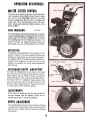
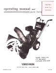
Your SNOW THROWER is a precision piece of snow throwing equipment. Engineering skill and experience have been combined to
provide the ultimate in safety and efficiency. As with any type of power equipment, carelessnessor error on the part of the operator
can result in injury. EXERCISE EXTREME CAUTION AT ALL TIMES.
2.
3.
4.
5.
6.
7.
8.
9.
a.
Replace
c.
10.
1.. READ THE OWNER'S MANUAL CAREFULLY.
Know the controls to operate your SNOW THROWER properly and how
to quickly stop th~unit.
BEFORE STARTING ENGINE, disengage all clutches and shift unit into neutral. Keep hands, feet and clothing away from
power driven parts.
DISENGAGE POWER AND STOP MOTOR before cleaning discharge, removing obstacles, making adjustments, or when
leaving operating position.
NEVER
snow.
DIRECT
DISCHARGE
.'.
AT BYSTANDERS
KEEP CHILDREN
AND PETS a safe distance away.
DO NOT ALLOW
CHILDREN
TO OPERATE
or allow anyone
MACHINE
in front
of machine -debris
or allow adults to operate machine without
ADJUST SCOOP HE IGHT to clear gravel or crushed rock surface.
EXERCISE
HANDLE
CAUTION
GASOLINE
to avoid slipping or falling, especially when operating
WITH CARE
-it
in reverse.
is highly flammable.
Use approved gasoline container.
b.
Never add gasoline to a running motor. Fill tank outdoors and wipe up spilled gasoline.
gasoline cap securely.
d.
Open doors if motor is running indoors -exhaust fumes are dangerous.
USE A GROUNDED
THREE-WI RE PLUG-IN
11. KEEP UNIT IN GOOD OPERATING
for all units equipped with electric starting kits.
CONDITION
may be hidden
and keep safety devices in place.
2
in the
proper instruction.
CE~
FREE OPERATION
,
GENERAL SNOW~THROWING
1.~ Always keep area to be cleaned cleared before~owfall~.
.
2.~. Always start engine with machine on level surface
';;;..""i" with
'-. master clutch disengaged: After starting, let engine warm up several
minutes
at
slow
speed
before
starting
to
remove
~now~
Ifinachine
is stored indoors, let engine and machine adjust to outdoor
temperatures before starting to throw snow':
...
..'co
3.
When throwing snow, ~u!:,machln.eat.~ull throttl~ for best re~lts:
.4.
When in deep heavy snow, shift to slowest speed,and start at the edge of area to be cleared, discharging snow to the outside.
."
5.
Always run engine a few minutes before storing, to dry moisture that collects inside of engine from blowing snow.
.,
,~~,.;..,.,
;",c.~i:,j;'i-",o\;,-,
"",,";"""""""J,""""';'._'
.
NOTE: NEVER RUN ENGINE INDOORS
OR IN AN ENCLOSED
AREA.
-."-"","...~
.,
'-
MAINTENANCE:
Your SNOW THROWER
like all machines with moving
contribute many trouble-free hours to your machine.
parts, must receive care and maintenance.
The following
tips, if used, will
1.
,~
Check engine oil level frequently, or every 5 hours of use. When changing oil, make sure dirt and debris is cleaned from oil
drain area before rem~ving oil plug. c
..'.
2;
Keep fan and auger housings clean.
3.
Check all nuts, bolts and screws occasio~ally for tightness to be sure machine is in good operating condition.
..4:
Should
shaft.
5.
6.
excessive
vibration
.y
develop,'check
'
f
..
. your
fan and
fan
shaft
immediately.
Do
not operate
the machine
with
a bent fan
or
The machine is pre-lubricated at the factory. However, lubrication with each usagewill prolong life of working parts.
If you are going to store your SNOW TH ROWER for any length of time (30 days or longer) it is important that the following
-.steps betaken.:
, .I
Drain the gas tank and carburetor. Start the engine and run it until out of gas.
Gasoline left in the engine will leave gum deposits in the carburetor and gas tank.
Clean engine
of all foreign matter:~
.-'
-'
,
.'
Lubricate cylinder by removing the sparkplug and pouring one ounce of clean
lubricating oil through the sparkplug hole into the cylinder. Crank engine slowly to
spread oil and replace sparkplug.
7
Should unusual vibration develop in transmission, remove rubber panel in rear cover and check rubber drive disc condition. For
reference seepage 11.
The belt tension is adjustable. The tensioning of belt should be checked every 5-10 hours of operation. Refer to adjustments
section for re-setting.
To prevent recoil freezing, when snow thrower is to be stored outside or in sub-freezing shelter, pull recoil rope out 6" to 12"
and tie knot in rope or fasten handle to keep rope from re-winding. This procedure will set inner parts in position for starting.
Just as your automobile nec:dsprofessional mechanical maintenance from time to time, so does your air-cooled engine. A yearly
tune-up and check by a qualified service center is recommended to avoid breakdowns and unnecessarydelays during the snow
throwing season.
MA1NTENAN
c.
b.
10.
9.
8.
3
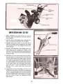
AND SET-UP
1. Before assembling your Snow Thrower be sure all
hardware, parts, and instructions have been removed
from the carton.
,
...:'
':;.'
'-2.
Assemble right and left handle tubes to the unit with
bolts, lockwashers, and flat washers. Do not tighten.3.
Assemble handle panel assembly to the under side of
right and left handle tubes and secure with four slotted
hex head bolts and lock nuts. Tighten all bolts on the
handle assembly.4.
Assemble chute adjustment shaft through hole in the
handle panel and into universal joint located on left
hand side of the frame. Align hole in universal joint with
the hole in chute adjustment shaft and drive spring pin
through the holes.
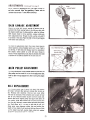
.':5.
Insert bent end of the master clutch rod into the hole in
the lower clutch arm (see top photo) and secure with
cotter pin. Move master clutch lever forward to the end
of the notch in the handle panel. To adjust, move link
up or down threaded portion of master clutch rod until
it is approximately one hole diameter below actual hole
in the master clutch lever (see photo). Move master
clutch lever back in notch until adjustment link slips
into the hole in master clutch lever. Secure with
cotter pin.
6. Insert shifter rod into the bushing on the end of the
shifting lever (see photo). Pivot shift lever upward and
secure to mounting bracket with bolt, washer, bushing,
and nut. Assemble threaded rod into end of shift lever
through the handle panel. Lock threaded rod in position
with nut. Refer to Page 7 for adjustment of shift
panel notches.
UNPACKING
4
BEFORE STARTING ENGINE
1. Fill the fuel tank with fresh winter blend regular gasoline. DO NOT MIX OIL WITH GASOLINE. Make
certain the fuel shut-off valve under the gas tank is
turned on.
2. Place machine on a level surface. Remove oil fill cap
and fill crankcase with good quality detergent oil.
Use MS classification SAE 5W-20 oil for operation
below 400F. Use MS classific:atio~ SAE 30 oil for
operation above 400F.
3. During initial "Break-in" period, the oil should be
checked often.
.
4. Change oil after first two (2) hours. of operation and
check oil level every five (5) operat~,:,ghours or each
time machine is used.
"
: 'f"
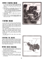
ENGINE
Shift the master clutch control to the Neutral position.
Move the choke lever to full choke position. Move speed
control lever to run position. Start the engine by pulling
rapidly on the recoil starter rope. As the engine starts and
begins to warm up, gradually return the choke lever to the
"No Choke" position.
NOTE: Temperatures 10°F. and below use "Primer." Push
primer button in and hold, pull engine slowly over compression once and 'release primer button. DO NOT
ATTEMPT TO START THE ENGINE WITH PRIMER
BUTTON HELD IN. (Do not use primer with 110 volt
electric starter.)
If the engine should fail to start, refer to your engine
Instruction Manual.
STOPPING THE ENGINE
To stop the engine move the speed control lever to the stop
position or close the fuel shut-off valve under the gasoline
tank. The sparkplug wire. may also be removed to prevent
accidental starting while. unattended. Always run engine a
few minutes before storing to dry moisture that collects
inside of engine from blowing snow.
BEFORE SNOW THROWING
1. Try your Snow Thrower machine in a large open space
with engine throttle in slow position. Learn to start, stop
and back-up during this trial run.2.
In rough areas, lower the adjustable skids.3.
Remove stones, wire, cans, boards, bones or other solid
objects from area to be cleared.4.
Always run engine a few minutes out-doors before
throwing snow, to adjust engine and machine to outside
air temperature.
STARTING
5
OPERATION OF CONTROLS
MASTERCLUrCH CONTROL
The master clutch control is located on handle panel and IS
used to engage,
all 'power~Select:8
forward speed or rever~
"
",,'c,';""...c"":,
with shift lever, then release
master
clutch control ,.and- push
, '.. c,
,,"
f,orward to engage ?rive diS?: f~~: reel. To disengage, puII
master
clutch control back and" lock
in ' notch. The master
."
, ,,'..
clutch
control
must
always'beln:
neutral
position before
-,
'~-""'"
,.'
-' -'
":!,
,
.
starting engine,;"'~
"'..
"
FREE ~' WHEELING
.~""",
'-
;'
~
...;;ii;F=::;i.'~
".
"~""'-
...
The wheel, ""..
clutchesc. are
located -,on wheels'
and are used to
'._1
,. ,
engage
or
disengage
powerto.wheels.,Tofree
the wheels
for
-'
,-"',
"c.,
,
""",,~~,,:
."
pushing,'pull
out
011
the
knob'
and
turn
to
lock.
To
provide
'..
"",t.,..
" ;~;'
-""".
.,
self-propelling,power:to
~he wheels.turn"clutches in the
opposite
direction
and
release.:':Thec
,
"
wheel
clutches
are
spring-loaded, .move unit until'theC~lutches lock to wheels.
DEFLECTOR
The deflector may be positioned in either a vertical or a 450
position in relation to the spout as needed for proper snow
deflection by loosening the two wing nuts on both sides of
the deflector. NOTE: For shipping purposes the deflector is
lowered off the hinging pin. Loosen the wing nuts and
reposition the deflector over the pin before operating the
Snow Thrower.
DISCHARGE CHUTE AND SPOUT
To rotate the discharge chute to the right or left, release
chute lock lever, then rotate with chute adjustment shaft to
desir~d position and lock. NOTE: The spout and deflector
rotates automatically when rotating the discharge chute to
the right and left. If it is desired to change position of the
spout, lift spout lock lever on the right hand side of unit
and hold while rotating the spout. Release the lever and
turn spout slightly until it !ocks into position.
ADJUSTMENTS
NOTE: Make all adjustments with the engine turned off
and wire "removed from the sparkplug. (Fasten wire to
cylinder head at least 1" away from sparkplug.)
DEPTH ADJUSTMENT
The adjustable skids may be set lower to prevent picking up
loose stone!; and foreign material. Also they can be raised 'to
allow the reel to slightly touch the ground for additional
pulling power.
6
.
To
.
REPLACING SAFETY SHEAR BOLT
If the intake snow reel should jam causing the safety shear
bolt to shear, it may be replaced with a new bolt, furnished
in the parts bag, after removing the broken pieces in the
shaft. NOTE: Always align the hole in the reel shaft and the
sprocket shaft before driving out the broken bolt. Do NOT
remove solid pin located near shear bolt hole.
CHUTE CHAIN AND-ADJUSTMENT
To tight~n the chute chain, rotate the chute all the way to
the left, until the adjustment bolt is accessible. Tighten the
adjustment nut to tighten the chain. ..'
:
."
.,,'
,
CAUTION: Chain must be kept snug on chute housing. "
CHUTE CABLE ADJUSTMENT
Remove cable roller cover, loosen the locking bolt on top
! of the cable roller bracket and tighten the adjustment bolt
on the side.
CAUTION: The cable should not be adjusted too tightly,
adjustment should allow the spout to rotate freely.
Retighten the locking bolt and replace the cable roller
cover.
SHIFT PANEL ADJUSTMENT
set or adjust the shift panel for correct speeds, place
master clutch control in neutral position and the shift lever
into the fifth speed notch. Loosen the two mounting bolts
and push shift lever right as far as allowed, hold, and
tighten mounting bolts. DO NOT ATTEMPT TH IS ADJUSTMENT WITH THE ENGINE RUNNING. To check
adjustment, start engine, move shift lever to first speed
notch and engage master clutch control. Unit should move
forward very slowly.
If first or reverse speeds are not satisfactory with this adjustment, move panel to the right for a faster first speed.
Move panel to the left for a faster reversespeed.
NOTE: Adjustment section continued on page 12.
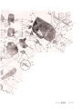
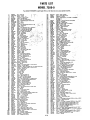
PARTS LIST
MODEL 7200-0
Your SNOW THROWER is right hand (R.H.I or left hand (L.H.I as you operate machine.
1
2
:I
4
6
6
7
8
9
10
11
12
13
14
16
16
17
18
19
20
21
22
23
24
25
26
27
28
29
30
31
32
33
34
35
36
37
38
39
40
41
42
43
44
45
46
47
48
49
50
51
52
53
54
55
56
57
48
59
60
61
64
65
66
68
69
70
71
72
73
74
75
76
77
78
79
80
81
82
83
84
85
86
87
88
89
90
91
92
93
94
95
96
97
98
99
100
101
102
103
104
1539-80
1658-29-40
41256
2119-4b
Nut -Push 1/2
Roller -Crenk
Wa,her-S.A,E,
1/2
A...mb!y-ChIJteCrank'"
i
:;
','
\."..'\'
,
"
3616-006
1538-30
40070
2643-51-40
1710-50-40
Decal- Handle Panel
Nut -Hex Lock 1/4-20 EsJok
Bolt -Flanged
Whizlock 1/4-20 x 1/2
Knob-Handle
-"T"
Grip
4712-99
1509-139
1616-459
Handle-L.H.
Bolt -Hex Head Slotted 1/4-20 x 1.1/2
Decal- Oparations
.'"
4712-98
40890
Handle -R.H.
Bolt -Hex Heed 5/16-18 x 1" Grade 5 f '
40149
40148
3-79
3609-580
Washer -Lock Spring Type 5/16
Washer -Standard Wrought 5/16
Bolt -Hex Head 5/16-18 x 3/4
Bracket-ShiftLeverMount.'::...,.
3153-36
~~~~~~
1~:~
Assembly -Handle
2
41'{)28
3709-33
2616-461
4122&
1674-47-40
42200
2705-40
1509-34
40892
1657-58
1552-9
1683-94
42342
2155-43
1509-17
1657..88
40153
1643-52-41
1548-14
1642-114
3609-579-41
40052
1540-137
1652-122
3110-71-41
40864
1657-71
2632-200
1646-23
22222
1657-61
1548-20
42373
3765-5
41182
1119-50
1509-136
1543-46
41299
1543-57
1652-115
1509-15
1650-50
2638-53
40157
2632-180
40790
1680-75
2632-178
42011
1509-137
1018
3626-91
1651-45
3675-20
1539-86
3622-115
2622-121-40
40050
2635-74
40735
1654-32
2638-52
1652-92
2622-118
1509-69
1650-51
1540-138
1657-65
1513-113
1513-125
2118-58
1539-90
f~~r:~
Panel
'.'
~\'c'
'"-
',,';...
,,;;,.
c";-'
, ",
,.~1i;
" ';
~~~.
,
".
-=-c~~~;~~~n
Nut -Hex Lock 5/16-24
..,
,,'
Panel -Shifting
"
.
Decal-ShiftingPanel
,-""
.'
i.
Knob -Shifting'.
,..
Cap -Chute Lock
Spring -Extension
Lever -Chute Lock
Bolt -Hex Head 1/4-20 x 3/4
Washer -S.A..E. 1/4
Bushing -Step
Washer -Wave
Rod -Shift Lever Extension
Nut -Hex Lock 3/8-16 Eslok
Assembly -Shifting
Lever
Bolt -Hex Head 5/16-18 xl"
Bushing -Spacer
Nut -Hex Lock (2-Way)
Assembly -Knob WI Lock Pin
Pin-Spring1/8x1"
Spring -Compression
Bracket -Wheel Lock
Pin -Spring
Washer-FlatSteeI51/64x1-1/4x1/32T.
Bushing -Flanged Wheal
Assembly -Wheel Complete L.H. 13 x 5.00-6 Pneumatic
Washer- Flat Steel 51/64 x 1-1/4x 1/16T.
Bushing -Spacer L.H.
Shaft -Wheel Axle
Key -Woodruff
Universal Joint
Bushing -Hex
Pin -Spring
Nut -Hex Lock 5/16-18
Strap -Scoop Mount L.H.
Nut-Hex
Lock (Esna3/4-16)
Assembly -Sprocket & Shaft
Bolt -Hex Head 3/8-16 x 1" Grade 5 Eslok
Washer -Flanged Retainer W/Oil Groove
Bushing -Spherical 20 MM
Washer -Flanged Retainer
Bushing-Spherical
3/4 Short
Bolt -Hex Head 1/4-20 x 1/2
Ring -Retaining
(External)
Sprocket -20 T.
Bolt -Hex Head Whizlock 5/16-18 x 5/8
Shaft -Offset
Pin -Spring
Arm -Lever (Clutch Rod)
Shaft -Intermediate
Key -Woodruff
3/16 x 5/8
Bolt -Hex Head (Self Tapping) 1/4-20 x 3/4
Washer -Lock
Spring Type 1/4
Pulley -"V"
Special 8"
Belt -"V"
4 L Special
Disc -Friction
Drive
Nut -Speed Grip 1/4-20
Cover-Rear
Frame
Cover Shift Lever Panel
Pin -Spring 5/16 x 2"
Gear -Spur 38 T.
Ring -Retaining
3/4
Chain -W/Conn.
Link #41 x 36 Pitches
SprocketWIHub 15T..
Bushing -Spherical 3/4
Cover -Gear (Lower)
Bolt -Hex Head 1/4-20 x 1-3/4
Ring -Retaining
(External) 11/16
Washer -Flat Steel 23/32 x 1-1/4 x 1/32 T.
Rushing -Step
Bol1- Shoulder 1/4-20
Bolt -Shoulder
1/4-20 Grade 5
Assembly -Chain Cover
Nut -Speed Grip 1/4-20
105
106
3622-122
3765-6
107
108
109
110
2168-55
1654-35
111
112
113
114'
115
116
117
118
119
c
-Cover-Chain
Strap -Scoop
(Inside)
Mount R.H.
..'.
,.
Assembly -Freme
Chain -Reel W/Conn. Link ~ 40 x 110 Pitch.
SeePage
SeePage 11
11
,
"
'3150-17
Assembly -Chute Frame Disc (Complete)
~'41362
Bushing-Oil
Filled
':; 3120-70
Aaembly -Cable Pulley
1509-126
Bolt Hex Heed 1/4-20 x 1/2 Grade 5
:: 40156
,Wesher-S.A.E.5/16
, 20263
Ceble-SteeI1/16Dia.x96"
60051
: Bracket -Cable Tightener
20110'
",' Roiler-Cabla
40108"
,\ Bushing -Chble Roller
120
2169-31
121 ,40152
;/
122. , 1657.04
123
1683-91
124
1625-31
125
,1169-32
126
41767
127
2609-440
1281642-111
129
41374
Assembly -Arm
(Clutch Linkaga)
Bolt -Hex Haed 5/16-18 x 1-1/2
8ushing -Step.',
Rod -Idler
LInk
Link -Rod -Connecting'
Assembly -Idler Arm;
Pin-Cotter
3/32 x 3/4
-c,
Bracket -Idler
Mount
Spring-Extension
Assembly-Pulley
Idler
130
131
132
133
134
135
136
137
138
139
140
141
142
143
144
145
146
147
148
149
150
151
152
153
154
155
156
157
158
159
160
161
162
163
164
165
166
167
168
169
170
171
172
173
175
176
177
178
179
180
181
182
185
186
187
188
189
190
191
2130-18
1609-542
40115
1513-36
2200-71
2659-22
1509-134
1657-40
22455
1657-41
1646-20
40794
1542-8
1509-105
4622-120
1616-458
42235
3556-14
20102
40085
3213-7
40100
1704-8
1511-44
1529-30
40496
3102-179
1513-122
1~0-145
1209-2
1654-34
40110
3622-123
40495
2197-6
42194
42195
42193
1509-117
1538-22
3609-438
1538-24
40160
3609-439
2713-10
1119-46
1657-83
1657-70
2616-607
2212-13
2121-17
1652-117
1642-110
1650-41
1540-118
1626-76
1657-60
1169-30
1513-112
Assembly -Engine Bese
Brecket -Support
(Belt Cover)
Nut -Speed (U-Type) 1/4-20
Bolt -Flenged Whizlock 1/4-20 x 5/8
Engine -8 H.P. Tecumseh
Guide -8elt Restrictor
Bolt -Hex Heed 5/16-24 x 1/2
Bushing -Spacer
Pulley -Engine
Bushing-Spacer
_C
Key -Pulley
Washer -Standard Wrought
Washer -Lock
3/8 Spring Type
Bolt -Hex Heed 3/8-24 x 1/2
Cover -Pulley & Belt
Decal- Belt Replacement
;
Decal -Spout Release
;:.
Deflector -Discharge
Nut -Wing
Washer -Cable Clamp
Assembly -Spout W/Flange
Bolt-CarriageShortSq,Neck5/16-18x1
Shoe -Retainer
Screw -Slotted
Hex Head #6 x 3/8
Bolt -Carriage 1/4-20 x 1/2
Screw -Hex Heed 5/16 x 1-1/2 Type B
Assembly -Blower
Housing & Chute
Screw-SelfTapping~10-32x3/4
Washer -Standard Wrought 3/16
Assembly -Chute
Chain
Chain W/Conn. Link ~41 x 32 Pitches
Bolt -Chain Connecting
Cover -Cable Roller Bracket
Screw -Slotted
Hex Head 5/16 x 1 Type B
Assembly -Fan
Nut -Hex Lock #8-32
Washer -Flat Steel ~8
Screw -Slotted
(Round Head) #8-32 x 1-3/4
Bolt-HexHead3/8-16xl-1/4Grade5
Nut -Hex Flanged Whizlock
Bracket -Scoop Mounting R.H.
Nut -Hex Lock 3/8 Ema
Bolt -Carriage 5/16-18 x 3/4
Bracket -Scoop Mounting L,H.
Skid-Scoop
Assembly-ReeIShaft&Plate
Bushing -Spacer
Bushing -Spacer
Decal- Caution
Assembly-Scoop
Assembly -Reel Sprocket
Bushing-Scoop
End7/8x 1 x 3/4
Spring-Extension
Ring -Retaining
(External 1/2)
Washer- Flat Steel 17/32 x 1-1/4x 1/16T.
Pulley -Chain Idler
8ushing -Chain Idler
Assembly -Arm
(Chain Idler)
Bolt -Shear
192
193
1540-141
3135-58-41
Washer-FlatSteel(AsNeeded)51/64x1-1/4x1/32T.
Assembly
-Reel
W/Bushing
194
195
196
197
198
199
200
202
203
204
205
206
207
208
40027
40883
1513-134
1513-41
1513-133
1745-24
1674-29
1511-33
3110-70-41
1547-42
1513-135
1522-11
1539-93
1552-16
Bushing -Oilite
Washer -Flat Steel (As needed) 25/32 x 1-1/4 x 1/32 T.
Bolt -Hex Head Thread Forming 5/1~18 x 1-1/4
Bolt -Hex Head Thread Forming 5/16-18 x 3/4
Bolt -Hex Head Thread Formin95/16-18
x 1-1/2
Pipe -Oil
Drain 1/4-18 NPT x 2-1/2
Cap -Oil
Drain 1/4-18 NPT
Bolt -Hex Head Thread Forming 1/4-20 x 1/2 "SEM"
Assembly -Wheel Complete R.H. 13 x 5.00-6 Pneumatic
Pin -Groove 5/16 Dia. x 2"
Bolt -Hex Head Thread Forming 5/16-18 x 1 (Eslok)
Screw -Slotted
Truss Head #10-12 x 1/2 (Type A)
NIJt -Speed Grip ~10A r'u" Type)
Washer -Bowed10-B
0",
,;:, i"',
'" .'" ,
..
:,
.,. t:;'~':,
,
11-8
PARTS LIST
REF.
PART
NO.
NO.
t
1654-31
2
-3
4
1624-192
1652-114
1149-5
.6
6
7
a
9
10
11
12
13
14
15
16
17
18
20
21
42342
1008
1646-24
2638-51
1624-191
1632.177
2111.107
1538-30
1018
1657-60
40148
42373
3150-20
2675.26
1509.90
2632.175
DESCRIPTION
Chain -W/Connactlng
Link
No.41 x 28 pitches
Spacer-Gear Sprocket
Baaring-Needla7/16x
1/2 L.
A-mbly
-Gaar & Sprocket W/Bearlng
(Included Ref. No.3)
Nut -Hex Lock 3/8.16 (Eslok)
Washer-SA.E.
3/8
Key -Woodruff 3/32 x 5/8 ~
Sprocket -aT
Spacer -Sprocket
Shaft -Gear & Sprocket
A_mbly-PlataPivotL.H.
Nut -Hax Lock 1/4-20 Eslok
Washer -Lock Spring Type (Light 1/4)
Bushing -Pivot
.35
Washer-Standard Wrought 5/16
Nut -Hex Lock 5/16-18 Esna
Assembly -Disc Drive Wheel W/Hub
Ring -Rubber
Drive
Bolt -Hex Head 1/4.20 x 1.1/4
Shaft -Hex
REF.
NO.
22
23
24
25
26~,c
27
28
29
30
31
32
33
34
36
37
3s
39
40
PART
NO.
42180
3606-146
1652-108
1629-14
1511-39
DESCRIPTION
Nut -Hex Lock No. 10-24 Esne
Plate -Pivot R.H.
Bearing -Ball Saaled
Flange -Retainer
Screw -Slotted Truss Head
No. 10-24 x 518
1540-99
Washer -Standard Wrought 114
40070
Bolt -Flanged Whizlock 114-20 x 1/2
40890 J .Bolt
-Hex Heed 5116-18 x 1"
(Grade 5) (Eslokl
1542-8
Washar -Lock Spring Type (Med) 318
2609-432
8racket -Mount (Pivot Plata)
1632-176
Shaft -Step
1657-63
Bushing -Sintered Bronza 314 x 718 x 1"
40035
Pin -Cotter 1/8 x 1"
1704-1
Shoe -Shifting
Yoke
2147-14
Assembly -Shifting Yoka
1777.6
Ear -Shift Yoke Stop
1683-90
Rod -Shifter
40735
Ring -Retaining 314
3114-19
Assembly -Friction
Drive Wheel, Complete
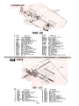
GEAR
REF.
NO.
1
2
3
4
5
6
7
8
9
10
11
12
PART
NO.
2632-174
1652-111
2635-72
40052
4609-441
1652-125
40735
40883
2635-70
1624-213-40
1650-49
1540-136
DESCRIPTION
Shaft-Fan20MM
Bearing-Ball
(Double Sealed) 204
Gear-BaveI18T.
Pin -Spring 5/16 Dia. x 1-1/2
Bracket -Gear Carrier
Bearing -Shaft Intagral
Ring -Retaining (External) 3/4
Washar- Flat Steel 25/32 x 1-1/4x 1/32
Gear-Spur 14T.
Sleeve -Shaft Cover
Ring -Retaining (External) 13/16
Washer-FletSteel
27/32 x 1-1/4x 1/32T.
REF.
NO.
13
14
15
16
17
18
19
20
21
22
23
24
25
PART
NO.
2635-69
42011
1624-190
1543-60
1652.124
1656-13
1652-113
2119-57
1650-50
1540-137
263s-71
40220
4132-138
DESCRIPTION
Geer -Spur 30 T.
Key-Woodruff3/16x5/S
Spacer -Gear
Washer -Thrust
Searing-Thrust
Seal- Oil 13/16 x 1-1/16
Bearing-Roller(NeedleJI3/16
A_mbly
-Shaft W/Sprocket
Ring -Retaining
(Externall 25/32
Washer-FlatSteeI51/64xl.1/4x1/32T.
Gear -Bevel 27 T.
Pin -Spring 5/16 x 1-3/4
Assembly -Gear Carrier Complete
NOTE:
Make
all
adjustments
...,
with
the
engine
turned
off
and wire removed from th~- sparkplug. (Fasten wire to
II
..,
cylinder head at least 1 away.from sparkplug.)
IDLER LINKAGE ADJUSTMENT
.:.~.
:a~.!...L:.
~
Should the drive belt stretch enough to prevent the ad
justment link from moving freely in the idler arm, slot, with
the master clutch lever in drive position, adjust' as follows.
With master clutch in drive position, remove cotter pin
.~
from adjustment link. Thread the link up the rod untir it.
is centered in the slot. Place the link in the slot and secure
..'--" washer and cotter PI,:!.
c.'
with
..'
To check the adjustment, return the master clutch lever to
neutral position and pull engine recoil over to see if belt is
not driving. If belt does not release, lower the adjustment
link slightly below center
or, until belt does release in
"
neutral. These adjustments must also be checked when belt
is replaced or the idler is adjusted in the idler arm slot.
IDLER PULLEY ADJUSTMENT
For more adjustment to gain proper tension on the belt, the
idler pulley can be moved in or out in the adjustment slot.
Refer to idler linkage adjustments after making this adjustment.
BELT REPLACEMENT
First. remove plastic cap on spout lock lever, then remove
belt cover. Unhook idler spring to release idler tension on
belt. Remove belt restrictor. Remove rear cover (after
shift lever is removed). This will allow one to reach in from
back of unit. Remove master clutch rod from lower arm.
Remove belt from engine pulley and push belt down off
drive pulley. Push belt,toward rear of unit around drive
disc, then pullI belt up b:'!tween rubber drive disc and pulley
disc. Push down on Ic'.'er arm on left side of unit, this
allows more room between rubber disc and pulley disc.
Reach in from back of unit and push belt up, then pull belt
out. To install new belt, reverse steps using only original
equipment replacement belt No. 1651-45.
12
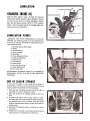
LUBRICATION-
CHANGING ENGINE OIL
Drain oil when engine is warm. To drain oil, place pan
under frame directly beneath oil drain extension. Remove
oil drain cap and allow oil to drain completely. Replace
drain cap and tighten securely. Refill to "Full", approximately 1 pint. See engine manual for complete engine lub.
rication and service instructions.
LUBRICATIONPOINTS
lUBRICATE
THE PARTS PERIODICAllY
AS IllUS-TRATED.
The following points are to be lubricated every
five hours of operation with SAE 20 weight light duty oil.
unless otherwise
noted.
1. Spherical Bearings (Both Sides)
2. Wheels
3.
4.
5.
6.
7.
8.
9.
10.
11.
12.
13.
Discharge Spout
Blower Housing
Reel Chain'
Chute Adjustment
.;':
Chain
Chain Guard Bushing
Universal Joint
Reel Bearings
Cable Rollers
Idler Arm & Linkage
Clutch Handle Pivot
Shift Yoke Slide
BREAK
IN PERIOD
CHECK All
;.:,
,1
,..
:~'
"AFTER
(FIRST 3 TO 4 HOURS OFOPERATION).
BOLTS AND NUTS FORTIGHTNESS.
END OF SEASON STORAGE
In the event the engine is to be stored for any length oftime
(30 days or more) or at the end of the snow throwing
season,prepare it asoutlined in the following steps:
1. Drain gas tank completely. by J_emoving-fuel line -at the
carburetor or fuel "tank, whichever is easier.2.
Drain the carburetor by pressing upward on the bowl
drain.3.
To protect the engine when storing, remove the sparkplug and inject one ounce of SAE 10 weight oil through
the sparkplug hole into the cylinder. Crank the engine
(without starting) several times to spread the oil over the
cylinder walls.4.
Lubricate all lubrication points as outlined in Lubrication Section.5.
Handles can be removed to savespace by disconnecting
master clutch rod, universal joint and shift lever.
cable roller bracket and down to the right hole in the
top of the blower housing.
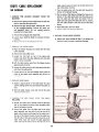
CHUTE CABLE REPLACEMENT
OR REPAIR
1. REMOVE THE
MACHINE.
C. Turn the cable pulley with the cable bolt toward the
bottom of , the blower
housing.
, "
.'\
'
.
BLOWER
HOUSIN~
D. Put the ends of the cable up through the holes in the
bottom of the cable pulley and cross the ends up and
over the cable bolt and under the washer. Pull the
cable tight and tighten the' ~ble bolt and nut, making
sure the cable remains in the track around the cable
pulley.
E. Slide cable pulley back into place.
FROM THE
A. Remove the ~ain guard and disconnect the reel drive
chain at the chain connecting link.
B. Re!:':1°vethe !.Ou! carriage-bolts, fastening the scoop
to the, mounting
brackets. .'Remove the: scoop and
-.,' .,,'"
reel
assembly'
"-
intact.'
Do
not
brackets from frame straps.
F. Tighten cable with adjusting cable bolt.
remove~~ mounting
". .",. c-
--
C. Remove the spring pin and remove fan;
"."'-
.-.',c"".
5. REPLACE THE BLOWER HOUSING
D. Loosen chute chain-to allow for removal of blower
A. Reverse the steps outlined in Step 1 to replace the
blower housing and parts to the Snow Thrower.
housing.
E. Remove the blower housing fromthe_unit;;-
2. REMOVETHE WORNCABLE.
A. Place the blower housing on a bench with the cable
pulley exposed.
.
B. Remove the cable roller cover.
C. Loosen the lock bolt on top of the cable roller
bracket and adjust the' cable adjusting bolt and cable
roller in as far as possible.
D. Lift the cable pulley away from the blower housing
:c. approximately 3 inches.
E. Loosen the cable mounting bolt and remove the'cable
ends from the cable pulley.
c.
F. Loosen the nut on the cable washer which holds the
cable to the upper spout assembly and remove the
worn cable.
3. REPLACENEWCABLE.:
, .
A. Fasten a loop in center of the cable under the cable
washer making certain that both ends of the cable are
even.
B. With the cable crossed, wrap each end of the cable
around the upper spout.
4. PLACING
ROLLERS.
THE
NEW
CABLE
OVER
THE
CABLE
A. Rotate the upper spout assembly with the discharge
side in the opposite direction from the cabie pulley
side of the blower housing.
B. Extend the cable from the right si~e of the upper
spout assembly over the roller on the left side of the
cable roller bracket and through the left cable hole in
the top of the blower housing. Extend the cable from
the left side of the spout assembly across the center
cable roll~r. back and around the cable adjustment
roller and over the cable roller on the right side of the
14
1~
.~';:;j
15
30"
SNOW
THROWERyou
enjoy these outstanding features
~
7/73