1
DEClaser 5100 Printer
Service Guide
Order Number: EK–LNX09–SV. A01
Digital Equipment Corporation
Maynard, Massachusetts
First Printing, April 1994
Digital Equipment Corporation makes no representations that the use of its products in the
manner described in this publication will not infringe on existing or future patent rights, nor do
the descriptions contained in this publication imply the granting of licenses to make, use, or sell
equipment or software in accordance with the description.
© Digital Equipment Corporation 1994/Digital Equipment Corporation.
Printed in USA
The following are trademarks of Digital Equipment Corporation: DECdirect, DEClaser,
PrintServer, ReGIS, VAX DOCUMENT, and the DIGITAL logo are trademarks of Digital
Equipment Corporation.
ITC Souvenir is a registered trademark of International Typeface Corporation.
PCL and LaserJet are registered trademarks of the Hewlett-Packard Company.
Microsoft is a registered trademark of Microsoft Corporation
WordPerfect is a registered trademark of WordPerfect Corporation
PostScript is a registered trademark of Adobe Systems, Inc.
Tektronix is a registered trademark of Tektronix, Inc.
All other trademarks and registered trademarks are the property of their respective holders.
The postpaid Reader’s Comments forms at the end of this document request your critical
evaluation to assist in preparing future documentation.
S2312
This document was prepared using VAX DOCUMENT Version 2.1.
Contents
Preface . . . . . . . . . . . . . . . . . . . . . . . . . . . . . . . . . . . . . . . . . . . . . . . . . . . . .
xi
1 Physical and Functional Description
1.1
1.2
1.3
1.4
1.5
1.5.1
1.5.2
1.6
1.7
1.8
Product and Servicing Safety Notes . . . . . . . . . . . .
Physical Description . . . . . . . . . . . . . . . . . . . . . . . .
Cassettes . . . . . . . . . . . . . . . . . . . . . . . . . . . . . . . .
Optional Feeders . . . . . . . . . . . . . . . . . . . . . . . . . .
Memory Options . . . . . . . . . . . . . . . . . . . . . . . . . .
Optional Hard Disk . . . . . . . . . . . . . . . . . . . . .
Expansion Memory . . . . . . . . . . . . . . . . . . . . .
Ethernet Network Board . . . . . . . . . . . . . . . . . . . .
Font (PCMCIA) Cartridges . . . . . . . . . . . . . . . . . .
Resolution/Graphics Enhancements Option Board .
.
.
.
.
.
.
.
.
.
.
.
.
.
.
.
.
.
.
.
.
.
.
.
.
.
.
.
.
.
.
.
.
.
.
.
.
.
.
.
.
.
.
.
.
.
.
.
.
.
.
.
.
.
.
.
.
.
.
.
.
.
.
.
.
.
.
.
.
.
.
.
.
.
.
.
.
.
.
.
.
.
.
.
.
.
.
.
.
.
.
.
.
.
.
.
.
.
.
.
.
.
.
.
.
.
.
.
.
.
.
1–1
1–2
1–12
1–14
1–18
1–18
1–18
1–19
1–20
1–21
.
.
.
.
.
.
.
.
.
.
.
.
.
.
.
.
.
.
.
.
.
.
.
.
.
.
.
.
.
.
.
.
.
.
.
.
.
.
.
.
.
.
.
.
.
.
.
.
.
.
.
.
.
.
.
.
.
.
.
.
.
.
.
.
.
.
.
.
.
.
.
.
.
.
.
.
.
.
.
.
.
.
.
.
.
.
.
.
.
.
.
.
.
.
.
.
.
.
.
.
.
.
.
.
.
.
.
.
.
.
.
.
.
.
.
.
.
.
.
.
.
.
.
.
.
.
.
.
.
.
.
.
.
.
.
.
.
.
.
.
.
.
.
.
.
.
.
.
.
.
.
.
.
.
.
.
.
.
.
.
.
.
.
.
.
.
.
.
.
.
.
.
.
.
.
.
2–2
2–4
2–6
2–8
2–9
2–10
2–12
2–12
2–14
2–15
2–16
2–16
2–17
2–17
2–18
2–18
2 Technical Description
2.1
2.1.1
2.1.2
2.1.3
2.1.4
2.1.5
2.1.6
2.2
2.2.1
2.3
2.3.1
2.3.2
2.3.3
2.3.4
2.3.5
2.3.6
Print Engine Control . . . . . . . . . . . . . . . . .
Video Controller Board and SmartPage
Print Engine Modes . . . . . . . . . . . . . . .
Low-voltage Power Supply Assembly . .
Fusing Heater Control . . . . . . . . . . . . .
Fusing Malfunction . . . . . . . . . . . . . . .
Interlocks . . . . . . . . . . . . . . . . . . . . . . .
Paper Feeding System . . . . . . . . . . . . . . . .
Size Sensing Cassettes . . . . . . . . . . . . .
Xerographic Process . . . . . . . . . . . . . . . . . .
Primary Charging Process . . . . . . . . . .
Exposure Process . . . . . . . . . . . . . . . . .
Development Process . . . . . . . . . . . . . .
Transfer Process . . . . . . . . . . . . . . . . . .
Separation Process . . . . . . . . . . . . . . . .
Print Drum Cleaning Process . . . . . . . .
.
.
.
.
.
.
.
.
.
.
.
.
.
.
.
.
.
.
.
.
.
.
.
.
.
.
.
.
.
.
.
.
.
.
.
.
.
.
.
.
.
.
.
.
.
.
.
.
.
.
.
.
.
.
.
.
.
.
.
.
.
.
.
.
.
.
.
.
.
.
.
.
.
.
.
.
.
.
.
.
.
.
.
.
.
.
.
.
.
.
.
.
.
.
.
.
iii
2.3.7
2.4
2.5
2.5.1
Fusing Process . .
Scanner . . . . . . . . . .
HVPSA . . . . . . . . . . .
EP-ED Cartridge
.
.
.
.
.
.
.
.
.
.
.
.
.
.
.
.
.
.
.
.
.
.
.
.
.
.
.
.
.
.
.
.
.
.
.
.
.
.
.
.
.
.
.
.
.
.
.
.
.
.
.
.
.
.
.
.
.
.
.
.
.
.
.
.
.
.
.
.
.
.
.
.
.
.
.
.
.
.
.
.
.
.
.
.
.
.
.
.
.
.
.
.
.
.
.
.
.
.
.
.
.
.
.
.
.
.
.
.
.
.
.
.
.
.
.
.
.
.
.
.
.
.
.
.
.
.
.
.
.
.
.
.
.
.
.
.
2–18
2–20
2–22
2–24
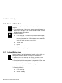
Control Panel Description . . . . . .
Control Panel Operation . . . . . . .
Online and Paused Messages .
Key Menu Modes . . . . . . . . . .
.
.
.
.
.
.
.
.
.
.
.
.
.
.
.
.
.
.
.
.
.
.
.
.
.
.
.
.
.
.
.
.
.
.
.
.
.
.
.
.
.
.
.
.
.
.
.
.
.
.
.
.
.
.
.
.
.
.
.
.
.
.
.
.
.
.
.
.
.
.
.
.
.
.
.
.
.
.
.
.
.
.
.
.
.
.
.
.
.
.
.
.
.
.
.
.
3–2
3–4
3–4
3–6
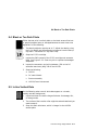
About the Test Page . . . . . . . . . . . . . . . . . . . . . . .
About the Menu Guide . . . . . . . . . . . . . . . . . . . . .
About the Demo Pages . . . . . . . . . . . . . . . . . . . . .
About the Print PS or PCL Menus Pages . . . . . . .
About the PCL Fonts and PostScript Fonts Lists .
About the PostScript Error Report . . . . . . . . . . . .
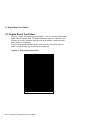
Engine Board Test Pattern . . . . . . . . . . . . . . . . . .
Locking and Unlocking the Set-Up Menu . . . . . .
Adjusting the Leading Edge Registration . . . . . . .
Reading the Page Count . . . . . . . . . . . . . . . . . . .
Formatting the Optional Disk . . . . . . . . . . . . . . .
.
.
.
.
.
.
.
.
.
.
.
.
.
.
.
.
.
.
.
.
.
.
.
.
.
.
.
.
.
.
.
.
.
.
.
.
.
.
.
.
.
.
.
.
.
.
.
.
.
.
.
.
.
.
.
.
.
.
.
.
.
.
.
.
.
.
.
.
.
.
.
.
.
.
.
.
.
.
.
.
.
.
.
.
.
.
.
.
.
.
.
.
.
.
.
.
.
.
.
.
.
.
.
.
.
.
.
.
.
.
.
.
.
.
.
.
.
.
.
.
.
.
.
.
.
.
.
.
.
.
.
.
4–2
4–3
4–4
4–5
4–6
4–7
4–8
4–9
4–10
4–11
4–12
3 Operating the Control Panel
3.1
3.2
3.2.1
3.2.2
4 Test Patterns and Miscellaneous Procedures
4.1
4.2
4.3
4.4
4.5
4.6
4.7
4.8
4.9
4.10
4.11
5 Start FIP and Total Call Concept
5.1
5.2
5.3
5.3.1
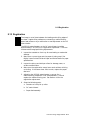
Preliminary Information . . . . . . . . .
Start FIP . . . . . . . . . . . . . . . . . . . . .
Total Call Concept (TCC) Procedure .
200K Maintenance Procedure . .
.
.
.
.
.
.
.
.
.
.
.
.
.
.
.
.
.
.
.
.
.
.
.
.
.
.
.
.
.
.
.
.
.
.
.
.
.
.
.
.
.
.
.
.
.
.
.
.
.
.
.
.
.
.
.
.
.
.
.
.
.
.
.
.
.
.
.
.
.
.
.
.
.
.
.
.
.
.
.
.
.
.
.
.
.
.
.
.
5–2
5–2
5–5
5–7
.
.
.
.
.
.
.
.
.
.
.
.
.
.
.
.
.
.
.
.
.
.
.
.
.
.
.
.
.
.
.
.
.
.
.
.
.
.
.
.
.
.
.
.
.
.
.
.
.
.
.
.
.
.
.
.
.
.
.
.
.
.
.
.
.
.
.
.
.
.
.
.
.
.
.
.
.
.
.
.
.
.
.
.
.
.
.
.
.
.
.
.
.
.
.
.
.
.
.
.
.
.
.
.
.
.
.
.
.
.
.
.
.
.
.
.
.
.
.
.
.
.
.
.
.
.
.
.
.
.
.
.
.
.
.
.
.
.
.
.
.
.
.
.
.
.
.
.
.
.
.
.
.
.
.
.
.
.
.
.
.
.
.
.
.
.
.
.
.
.
.
.
.
.
.
.
6–2
6–5
6–7
6–8
6–9
6–10
6–11
6–12
6 Power and Control Panel FIPs
6.1
6.2
6.3
6.4
6.5
6.6
6.7
6.8
iv
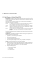
Bad Power or Control Panel FIPs . .
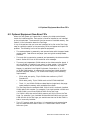
Optional Equipment Non-Error FIPs
Insert or Remove Cartridge . . . . . .
Load Env (Value) . . . . . . . . . . . . . . .
Load Front or Manual Feed . . . . . . .
Load LCIT (Value) . . . . . . . . . . . . . .
Load or Install Inter (Value) . . . . . .
Memory Overflow or Print Overrun .
6.9
6.10
6.11
6.12
6.13
6.14
6.15
6.16
6.17
6.17.1
No Toner Cart or Toner Low . . . . . . . . . . . . . . .
Printer Open . . . . . . . . . . . . . . . . . . . . . . . . . . .
All Hard Disk Errors . . . . . . . . . . . . . . . . . . . . .
50 ERROR . . . . . . . . . . . . . . . . . . . . . . . . . . . . .
51 or 52 ERROR . . . . . . . . . . . . . . . . . . . . . . . .
57 ERROR . . . . . . . . . . . . . . . . . . . . . . . . . . . .
58 ERROR . . . . . . . . . . . . . . . . . . . . . . . . . . . .
68 Service . . . . . . . . . . . . . . . . . . . . . . . . . . . . .
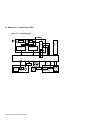
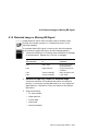
Print Engine Wiring Diagrams . . . . . . . . . . . . .
Envelope Feeder and LCIT Wiring diagrams
.
.
.
.
.
.
.
.
.
.
.
.
.
.
.
.
.
.
.
.
.
.
.
.
.
.
.
.
.
.
.
.
.
.
.
.
.
.
.
.
.
.
.
.
.
.
.
.
.
.
.
.
.
.
.
.
.
.
.
.
.
.
.
.
.
.
.
.
.
.
.
.
.
.
.
.
.
.
.
.
.
.
.
.
.
.
.
.
.
.
.
.
.
.
.
.
.
.
.
.
.
.
.
.
.
.
.
.
.
.
.
.
.
.
.
.
.
.
.
.
.
.
.
.
.
.
.
.
.
.
6–13
6–14
6–15
6–16
6–17
6–18
6–19
6–20
6–20
6–25
7 FIPs for Fixing Paper Jams
7.1
7.2
7.3
7.4
7.5
Types of Jams . . . . . . . . . . . . . . . .
Identifying the Location of the Jam
Paper Feed Area Jams . . . . . . . . .
Fusing and Delivery Area Jams . . .
Phantom Jams . . . . . . . . . . . . . . . .
.
.
.
.
.
.
.
.
.
.
.
.
.
.
.
.
.
.
.
.
.
.
.
.
.
.
.
.
.
.
.
.
.
.
.
.
.
.
.
.
.
.
.
.
.
.
.
.
.
.
.
.
.
.
.
.
.
.
.
.
.
.
.
.
.
.
.
.
.
.
.
.
.
.
.
.
.
.
.
.
.
.
.
.
.
.
.
.
.
.
.
.
.
.
.
.
.
.
.
.
.
.
.
.
.
.
.
.
.
.
.
.
.
.
.
7–2
7–2
7–4
7–6
7–6
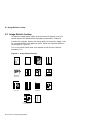
Image Defects Lookup . . . . . . . . . . . . .
Light or Faint Images . . . . . . . . . . . . .
Blank or White Prints . . . . . . . . . . . . .
Black or Too Dark Prints . . . . . . . . . . .
In-line Vertical Dots . . . . . . . . . . . . . . .
Dirt on Back of Page . . . . . . . . . . . . . .
Vertical Black Lines . . . . . . . . . . . . . . .
Black Smudged Vertical Bands . . . . . .
Black Smudged Horizontal Bands . . . .
Blank or White Spots . . . . . . . . . . . . .
Vertical White Lines . . . . . . . . . . . . . .
Registration . . . . . . . . . . . . . . . . . . . . .
Fusing Failure . . . . . . . . . . . . . . . . . . .
Distorted Image or Missing BD Signal .
Repetitive Marks . . . . . . . . . . . . . . . .
.
.
.
.
.
.
.
.
.
.
.
.
.
.
.
.
.
.
.
.
.
.
.
.
.
.
.
.
.
.
.
.
.
.
.
.
.
.
.
.
.
.
.
.
.
.
.
.
.
.
.
.
.
.
.
.
.
.
.
.
.
.
.
.
.
.
.
.
.
.
.
.
.
.
.
.
.
.
.
.
.
.
.
.
.
.
.
.
.
.
.
.
.
.
.
.
.
.
.
.
.
.
.
.
.
.
.
.
.
.
.
.
.
.
.
.
.
.
.
.
.
.
.
.
.
.
.
.
.
.
.
.
.
.
.
.
.
.
.
.
.
.
.
.
.
.
.
.
.
.
.
.
.
.
.
.
.
.
.
.
.
.
.
.
.
.
.
.
.
.
.
.
.
.
.
.
.
.
.
.
.
.
.
.
.
.
.
.
.
.
.
.
.
.
.
.
.
.
.
.
.
.
.
.
.
.
.
.
.
.
.
.
.
.
.
.
.
.
.
.
.
.
.
.
.
.
.
.
.
.
.
.
.
.
.
.
.
.
.
.
.
.
.
.
.
.
.
.
.
.
.
.
.
.
.
.
.
.
.
.
.
.
.
.
.
.
.
.
.
.
.
.
.
.
.
.
.
.
.
.
.
.
.
.
.
.
.
.
.
.
.
.
.
.
.
.
.
.
.
.
8–2
8–3
8–4
8–5
8–5
8–6
8–7
8–7
8–7
8–8
8–8
8–9
8–10
8–11
8–12
8 FIPs For Fixing Image Defects
8.1
8.2
8.3
8.4
8.5
8.6
8.7
8.8
8.9
8.10
8.11
8.12
8.13
8.14
8.15
v
9 Removing and Replacing FRUs
9.1
9.2
9.3
9.4
9.5
9.6
9.7
9.8
9.9
9.10
9.11
9.12
9.12.1
9.13
9.14
9.15
9.16
9.17
9.18
9.19
9.20
9.21
9.21.1
9.22
9.22.1
9.23
9.24
9.25
9.26
9.27
9.28
9.29
9.30
9.31
9.32
9.33
9.34
9.35
vi
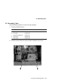
Removing and Replacing FRUs . . . . . . . . . . . . .
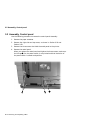
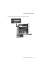
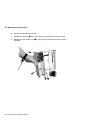
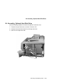
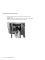
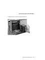
Assembly, Control panel . . . . . . . . . . . . . . . . . .
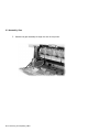
Assembly, Gear . . . . . . . . . . . . . . . . . . . . . . . . .
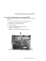
Assembly, High-Voltage Power Supply (HVPSA)
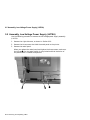
Assembly, Low-Voltage Power Supply (LVPSA) .
Assembly, Optional Hard Disk Drive . . . . . . . .
Assembly, Paper Delivery . . . . . . . . . . . . . . . . .
Assembly, Feed . . . . . . . . . . . . . . . . . . . . . . . . .
Assembly, Scanner . . . . . . . . . . . . . . . . . . . . . .
Board, LCIT Controller . . . . . . . . . . . . . . . . . . .
Board, Feed Controller . . . . . . . . . . . . . . . . . . .
Board, DC Control . . . . . . . . . . . . . . . . . . . . . .
Page Count Memory (NVRAM) . . . . . . . . . .
Board, Ethernet . . . . . . . . . . . . . . . . . . . . . . . .
Board, SIMMs . . . . . . . . . . . . . . . . . . . . . . . . . .
Board, Video Controller . . . . . . . . . . . . . . . . . . .
Cage, Card . . . . . . . . . . . . . . . . . . . . . . . . . . . . .
Cartridge, EP-ED (toner) . . . . . . . . . . . . . . . . .
Cover, Left-Side . . . . . . . . . . . . . . . . . . . . . . . . .
Cover, Right-Side . . . . . . . . . . . . . . . . . . . . . . . .
Cover, Top Cover . . . . . . . . . . . . . . . . . . . . . . . .
Door, Rear . . . . . . . . . . . . . . . . . . . . . . . . . . . . .
Rear Door Latch . . . . . . . . . . . . . . . . . . . . . .
Door, Front and Guide Plate . . . . . . . . . . . . . . .
Guide Plate . . . . . . . . . . . . . . . . . . . . . . . . .
Fan Exhaust . . . . . . . . . . . . . . . . . . . . . . . . . . .
Feeder, Envelope . . . . . . . . . . . . . . . . . . . . . . . .
Fusing Unit . . . . . . . . . . . . . . . . . . . . . . . . . . .
Guide, HVPSA Contact Plate . . . . . . . . . . . . . . .
Interconnect, HVPSA/Fuser . . . . . . . . . . . . . . . .
Motor, Main . . . . . . . . . . . . . . . . . . . . . . . . . . .
Motor, LCIT Pickup . . . . . . . . . . . . . . . . . . . . .
Pad, Front Tray Separation . . . . . . . . . . . . . . .
Roller Transfer . . . . . . . . . . . . . . . . . . . . . . . . .
Roller, Cassette Pickup . . . . . . . . . . . . . . . . . . .
Roller, Front Tray Pickup . . . . . . . . . . . . . . . . .
Roller, LCIT Pickup . . . . . . . . . . . . . . . . . . . . . .
Sensor, Fusing Exit/Rear Door . . . . . . . . . . . . . .
.
.
.
.
.
.
.
.
.
.
.
.
.
.
.
.
.
.
.
.
.
.
.
.
.
.
.
.
.
.
.
.
.
.
.
.
.
.
.
.
.
.
.
.
.
.
.
.
.
.
.
.
.
.
.
.
.
.
.
.
.
.
.
.
.
.
.
.
.
.
.
.
.
.
.
.
.
.
.
.
.
.
.
.
.
.
.
.
.
.
.
.
.
.
.
.
.
.
.
.
.
.
.
.
.
.
.
.
.
.
.
.
.
.
.
.
.
.
.
.
.
.
.
.
.
.
.
.
.
.
.
.
.
.
.
.
.
.
.
.
.
.
.
.
.
.
.
.
.
.
.
.
.
.
.
.
.
.
.
.
.
.
.
.
.
.
.
.
.
.
.
.
.
.
.
.
.
.
.
.
.
.
.
.
.
.
.
.
.
.
.
.
.
.
.
.
.
.
.
.
.
.
.
.
.
.
.
.
.
.
.
.
.
.
.
.
.
.
.
.
.
.
.
.
.
.
.
.
.
.
.
.
.
.
.
.
.
.
.
.
.
.
.
.
.
.
.
.
.
.
.
.
.
.
.
.
.
.
.
.
.
.
.
.
.
.
.
.
.
.
.
.
.
.
.
.
.
.
.
.
.
.
.
.
.
.
.
.
.
.
.
.
.
.
.
.
.
.
.
.
.
.
.
.
.
.
.
.
.
.
.
.
.
.
.
.
.
.
.
.
.
.
.
.
.
.
.
.
.
.
.
.
.
.
.
.
.
.
.
.
.
.
.
.
.
.
.
.
.
.
.
.
.
.
.
.
.
.
.
.
.
.
.
.
.
.
.
.
.
.
.
.
.
.
.
.
.
.
.
.
.
.
.
.
.
.
.
.
.
.
.
.
.
.
.
.
.
.
.
.
.
.
.
.
.
.
.
.
.
.
.
.
.
.
.
.
.
.
.
.
.
.
.
.
.
.
.
.
.
.
.
.
.
.
.
.
.
.
.
.
.
.
.
.
.
.
.
.
.
.
.
.
.
.
.
.
.
.
.
.
.
.
.
.
.
.
.
.
.
.
.
.
.
.
.
.
.
.
.
.
.
.
.
.
.
.
.
.
.
.
.
.
.
.
9–1
9–2
9–5
9–7
9–8
9–11
9–15
9–18
9–21
9–23
9–27
9–29
9–32
9–33
9–35
9–37
9–39
9–40
9–41
9–43
9–45
9–47
9–49
9–50
9–52
9–54
9–57
9–59
9–60
9–70
9–74
9–75
9–78
9–79
9–80
9–81
9–83
9–84
10 FRU Part Numbers
10.1
Field Replaceable Units . . . . . . . . . . . . . . . . . . . . . . . . . . . . . . . .
10–1
A Key Menu Map, Features, and Values
A.1
A.2
Key Menu Map . . . . . . . . . . . . . . . . . . . . . . . . . . . . . . . . . . . . . .
Key Menu Messages . . . . . . . . . . . . . . . . . . . . . . . . . . . . . . . . . . .
A–1
A–8
B General Information
B.1
B.2
B.2.1
B.2.2
B.2.3
B.3
B.3.1
B.4
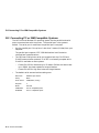
Connecting to an Ethernet Network . . . . . . . . . . .
Connecting PC or IBM Compatible Systems . . . . .
Configuring AUTOEXEC Files . . . . . . . . . . . . .
MS–DOS Drivers . . . . . . . . . . . . . . . . . . . . . . .
Windows and Windows NT Drivers . . . . . . . . .
Connecting the Printer to a Macintosh Computer .
Macintosh Printer Driver . . . . . . . . . . . . . . . . .
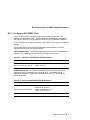
Connecting to OpenVMS VAX or ULTRIX Systems
.
.
.
.
.
.
.
.
.
.
.
.
.
.
.
.
.
.
.
.
.
.
.
.
.
.
.
.
.
.
.
.
.
.
.
.
.
.
.
.
.
.
.
.
.
.
.
.
.
.
.
.
.
.
.
.
.
.
.
.
.
.
.
.
.
.
.
.
.
.
.
.
.
.
.
.
.
.
.
.
.
.
.
.
.
.
.
.
B–1
B–2
B–3
B–4
B–4
B–5
B–6
B–7
Operating Requirements . . . . . . . . . . . . . . . . . . . . . . . . . . . . . . .
Space Requirements . . . . . . . . . . . . . . . . . . . . . . . . . . . . . . . .
Environmental Requirements . . . . . . . . . . . . . . . . . . . . . . . .
C–4
C–4
C–6
C DEClaser 5100 Specifications
C.1
C.1.1
C.1.2
D Training, Documentation and Tools
D.1
D.2
D.3
Training . . . . . . . . . . . . . . . . . . . . . . . . . . . . . . . . . . . . . . . . . . . .
Documentation Ordering Information . . . . . . . . . . . . . . . . . . . . .
Tools . . . . . . . . . . . . . . . . . . . . . . . . . . . . . . . . . . . . . . . . . . . . . .
D–1
D–2
D–3
Index
Figures
1–1
1–2
1–3
1–4
1–5
Front View . . . . . . . . .
Front Tray Open . . . .
Inside the Top Door . .
Rear Panel . . . . . . . . .
LCIT Interconnection .
.
.
.
.
.
.
.
.
.
.
.
.
.
.
.
.
.
.
.
.
.
.
.
.
.
.
.
.
.
.
.
.
.
.
.
.
.
.
.
.
.
.
.
.
.
.
.
.
.
.
.
.
.
.
.
.
.
.
.
.
.
.
.
.
.
.
.
.
.
.
.
.
.
.
.
.
.
.
.
.
.
.
.
.
.
.
.
.
.
.
.
.
.
.
.
.
.
.
.
.
.
.
.
.
.
.
.
.
.
.
.
.
.
.
.
.
.
.
.
.
.
.
.
.
.
.
.
.
.
.
.
.
.
.
.
.
.
.
.
.
.
.
.
.
.
.
.
.
.
.
1–2
1–4
1–6
1–8
1–10
vii
1–6
1–7
1–8
1–9
1–10
2–1
2–2
2–3
2–4
2–5
2–6
2–7
2–8
2–9
2–10
2–11
2–12
3–1
3–2
4–1
4–2
4–3
4–4
4–5
4–6
4–7
4–8
6–1
6–2
6–3
6–4
6–5
6–6
6–7
7–1
8–1
8–2
viii
Universal Cassette . . . . . . . . . . . . . . . . . .
LCIT . . . . . . . . . . . . . . . . . . . . . . . . . . . . .
Envelope Feeder . . . . . . . . . . . . . . . . . . . . .
Ethernet Network Board . . . . . . . . . . . . . .
Font Cartridge Installation . . . . . . . . . . . .
Overall Block Diagram . . . . . . . . . . . . . . . .
Video Controller Block Diagram . . . . . . . . .
Print Engine Modes Timing Diagram . . . .
LVPSA Diagram . . . . . . . . . . . . . . . . . . . . .
Fusing Temperature Chart . . . . . . . . . . . . .
Discharging C202 . . . . . . . . . . . . . . . . . . . .
Fusing Control Circuits . . . . . . . . . . . . . . .
Interlock Diagram . . . . . . . . . . . . . . . . . . .
Xerographic Process . . . . . . . . . . . . . . . . .
Scanning System Diagram . . . . . . . . . . . . .
HVPSA Control Circuit . . . . . . . . . . . . . . .
EP-ED Cartridge . . . . . . . . . . . . . . . . . . . .
Control Panel . . . . . . . . . . . . . . . . . . . . . . .
Overall Key Menu Map . . . . . . . . . . . . . . .
Test (Power Up) Page . . . . . . . . . . . . . . . . .
Menu Guide . . . . . . . . . . . . . . . . . . . . . . . .
Demo Page . . . . . . . . . . . . . . . . . . . . . . . . .
PostScript and PCL Settings Pages . . . . . .
Font Lists . . . . . . . . . . . . . . . . . . . . . . . . . .
PostScript Error Report . . . . . . . . . . . . . . .
Engine Board Test Pattern . . . . . . . . . . . . .
VR202 Registration Adjustment . . . . . . . . .
LVPSA Diagram . . . . . . . . . . . . . . . . . . . . .
Print Engine Wiring Diagram 1 . . . . . . . . .
Print Engine Wiring Diagram 2 . . . . . . . . .
Print Engine Wiring Diagram 3 . . . . . . . . .
Print Engine Wiring Diagram 4 . . . . . . . . .
Optional Envelope Feeder Wiring Diagram
LCIT Wiring Diagram . . . . . . . . . . . . . . . .
Jam Areas . . . . . . . . . . . . . . . . . . . . . . . . .
Image Defects Directory . . . . . . . . . . . . . . .
Roller Defect Ruler . . . . . . . . . . . . . . . . . . .
.
.
.
.
.
.
.
.
.
.
.
.
.
.
.
.
.
.
.
.
.
.
.
.
.
.
.
.
.
.
.
.
.
.
.
.
.
.
.
.
.
.
.
.
.
.
.
.
.
.
.
.
.
.
.
.
.
.
.
.
.
.
.
.
.
.
.
.
.
.
.
.
.
.
.
.
.
.
.
.
.
.
.
.
.
.
.
.
.
.
.
.
.
.
.
.
.
.
.
.
.
.
.
.
.
.
.
.
.
.
.
.
.
.
.
.
.
.
.
.
.
.
.
.
.
.
.
.
.
.
.
.
.
.
.
.
.
.
.
.
.
.
.
.
.
.
.
.
.
.
.
.
.
.
.
.
.
.
.
.
.
.
.
.
.
.
.
.
.
.
.
.
.
.
.
.
.
.
.
.
.
.
.
.
.
.
.
.
.
.
.
.
.
.
.
.
.
.
.
.
.
.
.
.
.
.
.
.
.
.
.
.
.
.
.
.
.
.
.
.
.
.
.
.
.
.
.
.
.
.
.
.
.
.
.
.
.
.
.
.
.
.
.
.
.
.
.
.
.
.
.
.
.
.
.
.
.
.
.
.
.
.
.
.
.
.
.
.
.
.
.
.
.
.
.
.
.
.
.
.
.
.
.
.
.
.
.
.
.
.
.
.
.
.
.
.
.
.
.
.
.
.
.
.
.
.
.
.
.
.
.
.
.
.
.
.
.
.
.
.
.
.
.
.
.
.
.
.
.
.
.
.
.
.
.
.
.
.
.
.
.
.
.
.
.
.
.
.
.
.
.
.
.
.
.
.
.
.
.
.
.
.
.
.
.
.
.
.
.
.
.
.
.
.
.
.
.
.
.
.
.
.
.
.
.
.
.
.
.
.
.
.
.
.
.
.
.
.
.
.
.
.
.
.
.
.
.
.
.
.
.
.
.
.
.
.
.
.
.
.
.
.
.
.
.
.
.
.
.
.
.
.
.
.
.
.
.
.
.
.
.
.
.
.
.
.
.
.
.
.
.
.
.
.
.
.
.
.
.
.
.
.
.
.
.
.
.
.
.
.
.
.
.
.
.
.
.
.
.
.
.
.
.
.
.
.
.
.
.
.
.
.
.
.
.
.
.
.
.
.
.
.
.
.
.
.
.
.
.
.
.
.
.
.
.
.
.
.
1–12
1–14
1–16
1–19
1–20
2–3
2–5
2–7
2–8
2–9
2–10
2–11
2–12
2–15
2–21
2–23
2–25
3–2
3–7
4–2
4–3
4–4
4–5
4–6
4–7
4–8
4–11
6–4
6–21
6–22
6–23
6–24
6–25
6–26
7–3
8–2
8–12
A–1
B–1
B–2
C–1
Key Menu Map . . . . . . . . . . . . . . . . . . . . . . . . . . . .
AppleTalk Network Connections . . . . . . . . . . . . . . .
EIA-232 and EIA-422 Cable/Adapter Configurations
Operating Space . . . . . . . . . . . . . . . . . . . . . . . . . . . .
.
.
.
.
.
.
.
.
.
.
.
.
.
.
.
.
.
.
.
.
.
.
.
.
.
.
.
.
A–2
B–5
B–8
C–5
Front View . . . . . . . . . . . . . . . . . . . . . . . . . . .
Front Tray . . . . . . . . . . . . . . . . . . . . . . . . . . .
Inside the Top Door . . . . . . . . . . . . . . . . . . . .
Rear View . . . . . . . . . . . . . . . . . . . . . . . . . . .
LCIT Interconnection . . . . . . . . . . . . . . . . . . .
Fixed and Universal Cassettes . . . . . . . . . . . .
LCIT . . . . . . . . . . . . . . . . . . . . . . . . . . . . . . .
Envelope Feeder . . . . . . . . . . . . . . . . . . . . . . .
Size Sensing Switches . . . . . . . . . . . . . . . . . .
Control Panel . . . . . . . . . . . . . . . . . . . . . . . . .
Indicators and Keys . . . . . . . . . . . . . . . . . . . .
Online and Paused Messages . . . . . . . . . . . . .
Start FIP . . . . . . . . . . . . . . . . . . . . . . . . . . . .
200K Maintenance Procedure . . . . . . . . . . . .
Types of jams . . . . . . . . . . . . . . . . . . . . . . . . .
Jam Areas . . . . . . . . . . . . . . . . . . . . . . . . . . .
Feed Area Swap Lists . . . . . . . . . . . . . . . . . .
FRUs . . . . . . . . . . . . . . . . . . . . . . . . . . . . . . .
Parallel Port AUTOEXEC.BAT Modifications
Serial Port AUTOEXEC.BAT Modifications . .
Printer Specifications . . . . . . . . . . . . . . . . . . .
Training . . . . . . . . . . . . . . . . . . . . . . . . . . . . .
Documentation . . . . . . . . . . . . . . . . . . . . . . . .
Tools . . . . . . . . . . . . . . . . . . . . . . . . . . . . . . . .
.
.
.
.
.
.
.
.
.
.
.
.
.
.
.
.
.
.
.
.
.
.
.
.
.
.
.
.
.
.
.
.
.
.
.
.
.
.
.
.
.
.
.
.
.
.
.
.
.
.
.
.
.
.
.
.
.
.
.
.
.
.
.
.
.
.
.
.
.
.
.
.
.
.
.
.
.
.
.
.
.
.
.
.
.
.
.
.
.
.
.
.
.
.
.
.
.
.
.
.
.
.
.
.
.
.
.
.
.
.
.
.
.
.
.
.
.
.
.
.
.
.
.
.
.
.
.
.
.
.
.
.
.
.
.
.
.
.
.
.
.
.
.
.
.
.
.
.
.
.
.
.
.
.
.
.
.
.
.
.
.
.
.
.
.
.
.
.
1–3
1–5
1–7
1–9
1–11
1–13
1–15
1–17
2–14
3–2
3–3
3–4
5–3
5–7
7–2
7–3
7–5
10–1
B–3
B–3
C–1
D–1
D–2
D–3
Tables
1–1
1–2
1–3
1–4
1–5
1–6
1–7
1–8
2–1
3–1
3–2
3–3
5–1
5–2
7–1
7–2
7–3
10–1
B–1
B–2
C–1
D–1
D–2
D–3
.
.
.
.
.
.
.
.
.
.
.
.
.
.
.
.
.
.
.
.
.
.
.
.
.
.
.
.
.
.
.
.
.
.
.
.
.
.
.
.
.
.
.
.
.
.
.
.
.
.
.
.
.
.
.
.
.
.
.
.
.
.
.
.
.
.
.
.
.
.
.
.
.
.
.
.
.
.
.
.
.
.
.
.
.
.
.
.
.
.
.
.
.
.
.
.
.
.
.
.
.
.
.
.
.
.
.
.
.
.
.
.
.
.
.
.
.
.
.
.
ix
Preface
This book is for Digital Service engineers to help them repair and service the
DEClaser 5100 printer. Before using this book, you must attend the specific
Digital Service training course and all other prerequisite training courses.
Section D.1 lists all recommended courses.
Conventions
The following conventions are used in this guide:
Convention
Description
Note:
Notes provide additional information.
Caution:
Cautions contain information to prevent damage to the
equipment or software.
Warning:
On Line
Value
PRNT
Warnings contain information to prevent personal injury.
All control panel keys are represented by a box with the name of
the key inside the box.
When this symbol appears next to a control panel message,
it shows that a string of numbers normally accompanies the
message. For example, in the Parity=Value message, the value
can be one of five different words.
A line over a signal name indicates that when the signal is
asserted, the signal is low.
How to Use this Guide
You can use this guide as a combined training document and for reference
information.
Use the table of contents or the fault isolation procedures (FIP)s to find the
section number of the information you need. The section header numbers (1.3,
2.3 and so on) are printed at the top of each page.
xi
xii
•
Chapter 1 identifies the significant external and internal components of the
standard printer and of the optional equipment.
•
Chapter 2 describes the paper handling, electromechanical operation, and
the xerographic processes.
•
Chapter 3 describes the control panel operation.
•
Chapter 4 describes the test prints and several miscellaneous procedures.
•
Chapter 5 contains the start FIP and the total call concept (TCC)
procedure.
•
Chapter 6 contains FIPs for fixing power, control panel, and error message
malfunctions.
•
Chapter 7 contains the paper jam FIPs.
•
Chapter 8 contains the image defect FIPs.
•
Chapter 9 contains procedures for removing and replacing field replaceable
units (FRU)s.
•
Chapter 10 contains the FRU part numbers.
•
Appendix A contains a map of the control panel key menus and a
glossary-style description of each feature and value.
•
Appendix B contains information on how to connect and configure the
DEClaser 5100 printer.
•
Appendix C contains the printer specifications.
•
Appendix D contains information about tools, training, and documentation.
Notes:
DSG-000172
1
1
Physical and Functional Description
This chapter provides a physical and functional description of the DEClaser
5100 printer and of the optional printer equipment.
1.1 Product and Servicing Safety Notes
Note: The DEClaser 5100 printer complies with all United States government
safety regulations applicable to ozone gas emissions and laser beam light
exposure.
Laser Safety: The DEClaser 5100 printer complies with 21 CFR Chapter 1,
Subchapter J, as a Class 1 laser product under the U.S. Department of Health
and Human Services (DHHS) Radiation Performance Standard, according to
the Radiation Control for Health and Safety Act of 1968. The DEClaser 5100
printer does not emit hazardous light because the laser beam is totally enclosed
during all modes of customer operation and maintenance.
Warning: Use of controls or adjustment procedures other than those specified
in this manual could result in hazardous laser light exposure.
Physical and Functional Description 1–1
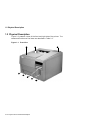
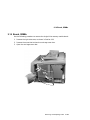
1.2 Physical Description
1.2 Physical Description
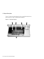
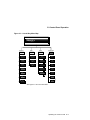
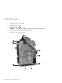
Figure 1–1 presents a view of the front and right side of the printer. The
names and functions of the items are described in Table 1–1.
Figure 1–1 Front View
2
3
DSG-000425
1
8
7
6
5
4
1–2 Physical and Functional Description
1.2 Physical Description
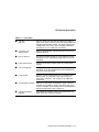
Table 1–1 Front View
!
Top door
and cover
Lifts for access to the EP-ED cartridge or for clearing
paper jams. When closed, a plastic post pushes down the
linkage to the interlock switch. The switch connects the
+24VB power to the main motor and paper feed motor.
See Section 2.1.3 for additional information.
Face down tray
delivery stack
Holds up to 250 sheets. This printer has no tray full or
job offset features.
#
Hot air exhaust
The main fan blows the hot air from inside the printer
through this vent. Overheating might result if the vent
is blocked.
$
Power on/off switch
Connects to the main LVPSA switch by a mechanical
linkage.
%
Font cartridge slot
Holds up to two optional PCMCIA font cartridges. The
cartridges can be hot swapped (with power applied) but
the printer must be paused.
&
Control panel
Consists of seven multipurpose keys, an alphanumeric
display panel, and indicators that light or flash to
show status conditions. See Chapter 3 for additional
information.
'
Internal paper cassette
Holds up to 250 sheets of xerographic paper. Internal
cassettes are available in fixed or universal sizes. The
universal cassette can be configured to accommodate the
standard sized sheets listed in Table 2–1.
Cassette full/empty
indicator
The mechanical indicator links to and moves with the
paper stack lifter inside the cassette.
"
(
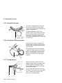
Physical and Functional Description 1–3
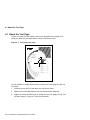
1.2 Physical Description
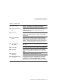
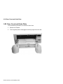
Figure 1–2 shows the components that are accessible through the front tray of
the printer. Table 1–2 describes the components.
Figure 1–2 Front Tray Open
2
DSG-000863
1
3
4
1–4 Physical and Functional Description
1.2 Physical Description
Table 1–2 Front Tray
!
"
#
$
Envelope feeder
connector
Connects the optional envelope feeder to the feed unit
controller. It is hidden by a panel when no envelope
feeder is installed. See Section 9.24 for envelope feeder
and panel installation.
Test print switch
Use a suitable tool to press this switch. When pressed,
the DC control board feeds and prints one copy of the
engine board test pattern from the internal cassette only.
See Section 4.7 for additional information.
Adjustable paper
guides
The adjustable guide is moved to hold the media against
the fixed guide. Image skewing, paper jams, or bad
image positioning can occur if the adjustable guide is too
loose or over-tightened.
Front tray
and door
Shown in the open position. The tray accommodates
standard size cut sheets and envelopes. The tray is
monitored by the paper end and front tray paper sensor.
Physical and Functional Description 1–5
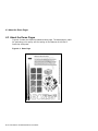
1.2 Physical Description
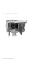
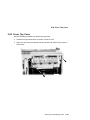
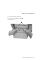
Figure 1–3 shows the inside components that are accessible through the top
door of the printer. Table 1–3 describes each component.
Figure 1–3 Inside the Top Door
2
3
4
DSG-000861
1
5
1–6 Physical and Functional Description
1.2 Physical Description
Table 1–3 Inside the Top Door
!
EP-ED connector block
The EP-ED connector block is part of the HVPSA
contact guide plate. The block carries the primary,
development, toner sensor, and ground currents to the
EP-ED cartridge. See Section 2.5.1 for more information.
"
Jam clearance plate
Opens to allow removal of jammed paper. Lift the green
handle to open the plate and disengage the upper oblique
rollers.
#
Transfer roller
The foam transfer roller is a crucial part of the
xerographic process. (See Section 2.3.3 for additional
information.) When you handle the transfer roller, only
touch the extreme ends. Fingerprints on the roller can
cause image defects.
$
Cleaning brush
The cleaning brush is used to sweep toner and dust out of
the static eliminator, which is located next to the transfer
roller. The hooked end of the brush is useful for removing
the transfer roller.
%
Registration sensor
This sensor detects paper feeding from any of the
standard or optional feed units. The DEClaser 5100
has no registration clutch or rollers.
Physical and Functional Description 1–7
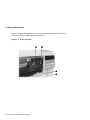
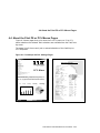
1.2 Physical Description
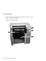
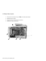
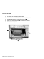
Figure 1–4 shows the components that are accessible through the rear door of
the printer. Table 1–4 describes each component.
Figure 1–4 Rear Panel
1
2
3
4
5
6
9
DSG-000582
7
8
1–8 Physical and Functional Description
1.2 Physical Description
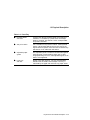
Table 1–4 Rear View
!
"
#
$
%
&
'
(
)
LocalTalk port
This port connector is for connecting to an AppleTalk
network. See Section B.3 for more information.
Parallel (Centronics)
port
Accepts a 36-pin connector cable. The connector is
physically and electronically compatible with the
Centronics protocol.
Serial port
This 25-pin connector electronically and electrically
complies with the EIA-232-D or CCITT V.24 interface
specifications.
Fusing assembly
levers
These two levers release the pressure on the fusing
pressure roller. The levers are up when the customer
first receives the DEClaser 5100 or if the fusing unit is
replaced. Operating the printer with one or both of the
levers up, causes fusing failure or paper jams to occur.
Fusing exit/rear
door sensor
This sensor monitors the fusing exit paper path and the
rear door.
Fusing exit
The fusing exit opens to allow removal of jammed paper.
Rear door
Press the latch to open the rear door to the position
shown. The door opens to allow the user to clear paper
jams.
Power cord
receptacle
Accepts the 115 or 220 Vac power line cord.
DECmultiNET 100e
connectors
These connectors accept standard Ethernet ThinWire
or Thickwire connectors. See Section 1.6 for more
information. If no DECmultiNET option is installed,
a block-off plate can be seen in place of these connectors.
Physical and Functional Description 1–9
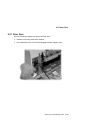
1.2 Physical Description
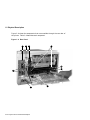
Figure 1–5 shows the components that are visible from underneath the printer.
Table 1–5 describes each component.
Figure 1–5 LCIT Interconnection
2
3
1
DSG-000583
4
1–10 Physical and Functional Description
1.2 Physical Description
Table 1–5 LCIT Interconnection
!
"
Cassette paper
feed roller
Feeds paper from the internal cassette into the
oblique rollers. The roller is replaced during the 200K
maintenance procedure described in Section 5.3.1.
Size sensing switches
There are two sets of size sensing switches: one in the
optional LCIT cassette slot and the other in the internal
cassette slot. Each set consists of three switches.
The size sensing switches read the configuration of
the keys on the side of the installed cassette. This
information is compared to the selected size by the
firmware. A mismatch causes an error to display.
#
$
LCIT interface
connector
This 4-pin connector connects the LCIT controller board
to the feed unit controller.
HVPSA
The HVPSA supplies the xerographic charge and bias
voltages.
Physical and Functional Description 1–11
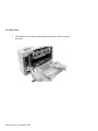
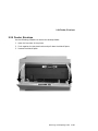
1.3 Cassettes
1.3 Cassettes
Figure 1–6 is a picture of the universal LCIT cassette. Table 1–6 describes the
cassette components.
Universal cassettes are available for the LCIT and for the internal cassette.
The internal cassettes are shallower and have a paper path slot in front.
Figure 1–6 Universal Cassette
2
1
8
DS
G
-0
00
58
4
3
7
6
5
4
1–12 Physical and Functional Description
1.3 Cassettes
Table 1–6 Fixed and Universal Cassettes
!
Paper path
Directs paper into the printer. When paper feeds from
the LCIT it feeds through the front of the internal
cassette. This area must be free of obstructions,
adhesive matter, and in good physical condition.
"
Rear paper guide
Holds the paper stack in good feeding position and
controls stack alignment.
If the rear guide is adjusted incorrectly, the paper stack
might misalign and cause paper jams and registrations
defects.
#
Side guides
Hold the paper stack in position and controls stack
alignment. The left side guide if fixed and the right
side guide is adjustable.
If the right side guide is adjusted incorrectly, the paper
stack can misalign and cause skewing and jams.
$
Size sensing keys
Actuate the size sensing switches on the side of the
cassette slot. The size information is compared with
the size entered in the menu or received from the
host. If a mismatch occurs, a paper size error appears.
Table 2–1 gives the key configuration for each paper
size.
%
Paper size adjuster
Sets the size-sensing keys. An incorrectly set paper size
causes false paper jams or paper mismatch errors.
Cassette full indicator
Shows the amount of paper remaining in the cassette.
Spring balance knob
On the LCIT universal cassette only. Knob adjusts the
spring pressure that lifts the stack up into the paper
feed roller. Adjust the knob to position the indicator in
the center of the window.
Paper corner guide
Holds the corner of the paper stack down. During paper
feeding, the corner of the top sheet of paper flicks out
from under the guide while underlying sheets do not.
This action prevents multiple sheet-feeding.
&
'
(
Physical and Functional Description 1–13
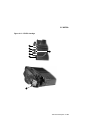
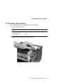
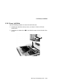
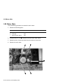
1.4 Optional Feeders
1.4 Optional Feeders
Figure 1–7 shows the DEClaser 5100 large capacity input tray (LCIT) and
Table 1–7 identifies the components.
Figure 1–7 LCIT
2
3
4
1
5
DSG
-000
586
6
8
1–14 Physical and Functional Description
7
1.4 Optional Feeders
Table 1–7 LCIT
!
Alignment pins
Mesh with holes in the base of the printer and provide
precise alignment.
"
Oblique rollers
Move the sheet through the internal cassette into the
paper feed unit.
#
Paper feed roller
Moves a sheet off the stack into the nip of the oblique
rollers.
$
Extender plate
Fits on the rear of the LCIT to cover the tail of the longer
cassettes.
%
Control board
Operates as a peripheral device to the paper feed
controller board. See Sections 2.1, 6.17.1, and 9.10
for more information.
&
Interface connector
A 4-pin connector that connects the LCIT controller board
to the feed unit controller.
'
Size sensing switches
Three size sensing switches read the configuration of the
keys on the side of the installed cassette. Table 1–6
shows and describes the size sensing keys. This
information is compared to the selected size by the
firmware. A mismatch causes an error to appear.
There are two sets of size sensing switches: one in
the optional LCIT cassette slot and one in the internal
cassette slot.
(
LCIT cassette
slot
Accepts a fixed or universal 500-sheet LCIT cassette. The
500 sheet LCIT cassettes are twice as deep as the 250
sheet internal cassettes.
Physical and Functional Description 1–15
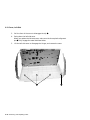
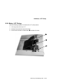
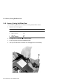
1.4 Optional Feeders
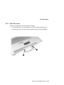
Figure 1–8 shows the DEClaser 5100 optional envelope feeder and Table 1–8
identifies the components.
The envelope feeder is a field replaceable unit.
Figure 1–8 Envelope Feeder
1
2
DSG
-00
047
1
4
3
1–16 Physical and Functional Description
1.4 Optional Feeders
Table 1–8 Envelope Feeder
!
"
#
$
Stack compressor
Presses the stack down into the envelope feed rollers.
Adjustable guide
Adjusts to hold the envelope stack against the left side of
the envelope feeder.
Support tray
Provides support for long envelopes.
Envelope feed rollers
Feeds envelopes from the bottom of the stack into the
printer.
Physical and Functional Description 1–17
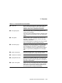
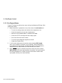
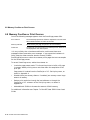
1.5 Memory Options
1.5 Memory Options
Font memory is an area of printer memory that stores downline-loaded fonts.
Once stored in font memory, the font stays until the printer is powered down.
Print jobs that downline-load many fonts expand the size of font memory until
memory overflow errors occur.
To deal with memory overflow errors, customers can increase font memory by
installing single in-line memory modules (SIMMs) or an optional hard disk
assembly.
1.5.1 Optional Hard Disk
The optional hard disk expands font memory by 127 non-volatile MB. The
downline-loaded fonts remain in the printer through power cycles. Storing
fonts on the disk leaves the RAM free for other needs.
The disk is customer installable and the disk formatting procedure is automatic
and interactive. See the following locations for additional information:
•
Section 4.11 contains the formatting procedure.
•
Section 6.11 contains the hard disk display messages and FIP.
•
Section 9.6 contains the hard disk assembly removal and replacement
procedure.
1.5.2 Expansion Memory
The video controller board has two expansion memory (SIMM) slots. Each
slot can hold a 4-, 16-, or 32-MB SIMM. The additional RAM increases the
available RAM to the video controller board. See the removal/replacement
procedure in Section 9.14 to install a SIMM.
1–18 Physical and Functional Description
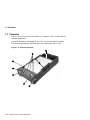
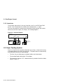
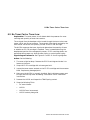
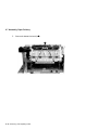
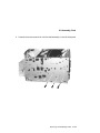
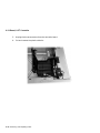
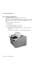
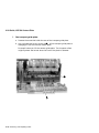
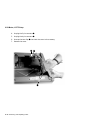
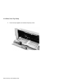
1.6 Ethernet Network Board
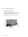
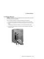
1.6 Ethernet Network Board
An optional Ethernet network board slides into the rear of the printer and
provides a ThinWire or twisted-pair connection.
DSG-000592
Figure 1–9 Ethernet Network Board
Physical and Functional Description 1–19
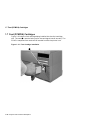
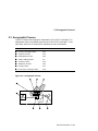
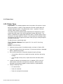
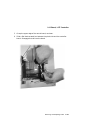
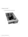
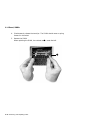
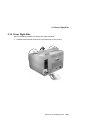
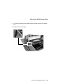
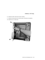
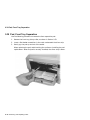
1.7 Font (PCMCIA) Cartridges
1.7 Font (PCMCIA) Cartridges
Figure 1–10 shows a font cartridge being installed into the font cartridge
slot. The notch
must be facing up for the cartridge to install correctly. The
PCMCIA compliant font cards can be inserted in while the printer is on.
!
Figure 1–10 Font Cartridge Installation
DSG-000580
1
1–20 Physical and Functional Description
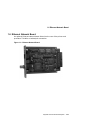
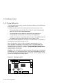
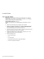
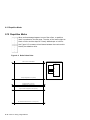
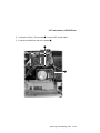
1.8 Resolution/Graphics Enhancements Option Board
1.8 Resolution/Graphics Enhancements Option Board
The optional Resolution/Graphics Enhancements (RGE) board is installed in a
connector on the video controller board. The connector socket is located above
the two SIMM sockets.
RGE image enhancement differs from DECimage enhancement. RGE creates
a 1200 x 1200 bit map in the video controller board memory; DECimage uses
a 600 x 600 dpi bitmap. This memory usage might cause memory overflow or
print overrun errors (described in Section 6.8) when printing complex images
or using many downline loaded fonts.
The RGE enhances the appearance of all PostScript and PCL images. Low
resolution image enhancement begins as soon as the RGE board is plugged in
and power is turned on. It cannot be enabled or disabled. Two high-resolution
features are available:
•
1200 x 600 dpi
•
1200 x 1200 dpi
Physical and Functional Description 1–21
1.8 Resolution/Graphics Enhancements Option Board
Notes:
DSG-000172
1–22 Physical and Functional Description
2
Technical Description
This chapter provides a technical description of the following major sections of
the DEClaser 5100 printer:
•
Section 2.1 describes the block diagram, operational modes, low-voltage
power supply assembly (LVPSA) and interlock systems, and presents board
and connector level wiring diagrams.
•
Section 2.2 describes the paper feeding system plus paper size sensing and
detection.
•
Section 2.3 describes the xerographic process.
•
Sections 2.4 and 2.5 present a detailed description of the scanner and
high-voltage power supply assembly (HVPSA).
See the detailed wiring diagrams in Figures 6–2 through 6–5.
Technical Description 2–1
2.1 Print Engine Control
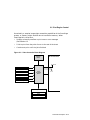
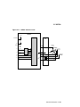
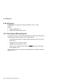
2.1 Print Engine Control
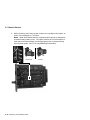
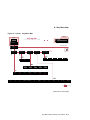
Figure 2–1 shows the overall block diagram of the DEClaser 5100 printer.
The shaded blocks indicate microcomputer-controlled devices. All nonshaded
components are operated by discrete binary signals.
The DC control board operates all the print engine devices, solenoids, sensors,
motors, and so on. The DC control board can operate the printer and print the
engine test pattern with no video control board installed.
Section 2.1.1 describes the operation and functioning of the video controller
board.
2–2 Technical Description
2.1 Print Engine Control
Figure 2–1 Overall Block Diagram
Scanner Unit
Laser Driver
BD
Developer Charge
DC
Control
Board
HVPSA
Contact
Plate
Transfer Charge
Static Eliminator
Toner Sensor
Main
Motor
DSG-000593
HVPSA
Video
Controller
Board
Primary Charge
Scanner Motor
Operator
Panel
Exit Sensor
Main Fan
Sensors Pickup
Motor Solenoids
Feed Unit
Control Board
Envelope Feeder
LCIT
LVPSA
Fusing Unit Heater
Technical Description 2–3
2.1 Print Engine Control
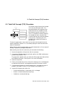
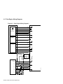
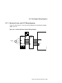
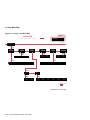
2.1.1 Video Controller Board and SmartPage
Figure 2–2 shows the video controller board mechanically and electronically
connecting and interfacing to the following standard and optional devices:
Standard devices:
•
The AppleTalk, parallel, and serial interface ports that allow direct
simultaneous connections to three different host computers
•
The operator panel provides users with control and status
•
The DC control board which operates the print engine
Optional devices:
•
One or two font cartridge
•
Optional hard disk drive
•
Optional XLI image enhancement board
•
Optional Ethernet network card
The video controller board accepts PostScript level 2 or PCL5E code files
from either the host or Ethernet interfaces and creates a bitmap image. The
bitmap is fed to the DC controller board as the V DO signal that is described in
Section 2.4.
Traditionally, an entire page is bitmapped into RAM before the printer is
commanded to feed and print. Such a system requires a considerable amount
of RAM memory.
SmartPage is the name of the process that the DEClaser 5100 printer uses to
create the printed image. Instead of bitmapping an entire page, this printer
bitmaps in bands. When one band is complete, it prints while the next band is
bitmapping. The SmartPage process uses about one-sixtieth as much RAM as
a full page bitmap requires.
2–4 Technical Description
2.1 Print Engine Control
Occasionally, a complex image might exceed the capabilities of the SmartPage
process, or memory might overflow due to insufficient memory. When
SmarPage fails, the printer:
•
Displays a memory overflow or print overrun error message
(See Section 6.8
•
Fails to print from the point of error to the end of the sheet
•
Continues to print until the job is finished
Figure 2–2 Video Controller Block Diagram
DC Control Board
Operator
Panel
+5Vdc
SIMMS
Parallel
Serial
Video
Controller
Board
AppleTalk
Font Cartridge 1
Font Cartridge 2
Disk Drive
RGE
Network Card
DSG-000594
Options
Technical Description 2–5
2.1 Print Engine Control
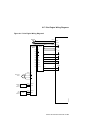
2.1.2 Print Engine Modes
Figure 2–3 shows the activity that occurs during the following DEClaser 5100
operational modes:
1. When the printer is powered on, the printer enters the wait mode and:
•
Turns on the fusing heater and monitors the temperature rise.
•
Checks the top door and rear door closed sensors
•
Makes sure the selected feeder is installed and loaded
•
Checks the EP-ED cartridge and toner empty signal
•
Runs the main and scanner motors
•
Turns the high-voltage bias supplies on and off
•
Cleans the transfer roller
2. If all the wait checks pass, the printer enters standby STBY mode
until a print request is received. During standby, fusing temperature
and interlocks are maintained. Standby ends when a print command is
received from the video controller or from the test print switch.
3. After a PRNT signal is received, the printer enters the initial rotation
(INTR mode) which lasts approximately six seconds. During this period
the fusing temperature is raised, the main and scanner motors come
up-to-speed, and the print drum stabilizes.
2–6 Technical Description
2.1 Print Engine Control
4. During print mode, the fusing temperature is maintained, interlocks are
tested, and printing is performed.
5. During the last rotation mode (LSTR) the last page of the job is ejected
and the transfer roller is cleaned. If a PRNT signal is received during this
mode, then initial rotation mode immediately begins.
Figure 2–3 Print Engine Modes Timing Diagram
Power On
WAIT
Fusing heater
STBY
INTR
PRINT
Flashing
READY/WAIT indicator
LSTR
STBY
Steady glow
162ºC
172ºC
183ºC
172ºC
PRINT (signal)
VSYNC (Vertical SYNC signal)
About 1
Main motor
About 4
Scanner motor
0.2
Primary AC charge
0.88
Primary DC charge
1.1
0.3
0.3
1.71
About 1
0.73
0.51
Develop DC charge
Negative bias
Between the pages bias
Print bias
0.65
Transfer ± charges
Technical Description 2–7
DSG-000595
Develop AC charge
2.1 Print Engine Control
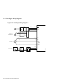
2.1.3 Low-voltage Power Supply Assembly
Figure 2–4 shows the circuits of the low-voltage power supply assembly
(LVPSA). If a short circuit or other fault draws excessive current from the
+24VA or +5V regulators, the output voltage decreases to a minimal level. To
reset the regulator, power the printer off and then on again.
The circuit breaker reset button is accessible through a hole on the side of the
LVPSA. The circuit breaker opens when a short circuit occurs in the LVPSA.
A shorted power regulator output should not trip the circuit breaker.
Note: A 6.3 amp fuse is used in place of the circuit breaker of power supplies
that carry the Sanken label.
When the top door is closed, the top door switch provides the +24VB to the
motors and high-voltage supplies.
Section 2.1.4 describes the operation of the fusing heater control circuit and
the THOUT , RLD , and FSRD signals.
Figure 2–4 LVPSA Diagram
Circuit
Breaker
Noise
Filter
Fusing
Heater
Control
+5V DC Power
Regulator
THOUT
J104F-3
RLD
-2
FSRD
-1
Video
Control
Board
+24VA DC Power
Regulator
J103-1
-2
-3
-4
-5 -6
J212-1 -2 -3
DC Control Board
+24VB
+5V
+5V
+24VB
Exit Sensor
Feed Unit
Controller
Board
Motor
Top Door
Switch
2–8 Technical Description
+5V
+5V
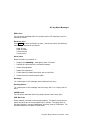
+5V
HVPSA
BD
Detector
Laser
+24VA
+5V
Fusing
Unit
Main
Motor
Scanner Assembly
Scanner
Motor
DSG-000596
+24VA
2.1 Print Engine Control
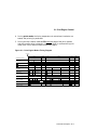
2.1.4 Fusing Heater Control
Figure 2–5 shows how the fusing temperature varies after power and during
printing and standby operations.
Figure 2–7 shows the circuitry that controls the fusing temperature. The
surface temperature of the upper fusing unit roller is measured by thermistor
(TH1) and adjusted by the DC control board.
The fusing temperature sets the resistance of TH1, establishing the voltage
level for the analog FSRTH signal. The resistance of TH1 decreases as the
fusing temperature increases. The following TH1 resistance readings are
measurable across pins 1 and 2 of the fusing unit connector (J743):
•
Room temperature resistance of TH1 is approximately 239K .
•
Operating temperature resistance of TH1 is less than 2.0K
.
Figure 2–5 Fusing Temperature Chart
Technical Description 2–9
2.1 Print Engine Control
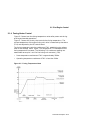
2.1.5 Fusing Malfunction
If a fusing malfunction occurs, dynamic and passive safety circuits disable the
fusing heater current.
The safety circuit opens RL101 and disconnects the fusing current if the:
•
Fusing temperature fails to reach 172°C (341.6°F) within 200 seconds of
power on, the DC control board asserts RLD .
•
Fusing temperature rises above the maximum high temperature
•
Fusing temperature falls below the minimum low temperature.
•
A short circuit occurs in the fusing heater or leads. The LVPSA senses the
increased current and forces the safety circuit to open RL101.
If an uncontrollable temperature rise occurs, the thermoswitch (TP1) opens to
permanently disconnect the fusing current.
When a fusing error occurs, C202 is charged to approximately +5 Vdc,
which prevents the operation of the fusing circuit. C202 discharges only
when the power is turned off. If power is turned on before the charge is
completely drained, C202 fully recharges. The printer must remain off for
approximately 10 minutes.
Caution: If you do the following, be sure to power off the printer and disconnect
the power cord. For service reasons only, C202 can be discharged by touching
the + lead of C202 to the metal chassis ground frame. Failure to power off the
printer can damage the DC control board.
Figure 2–6 Discharging C202
VR202
J203
J206
J207
J204
J208
J205
J201
J209
–
C202
TB201
2–10 Technical Description
J211
J210
DSG-000598
J212
+
–
C201
2.1 Print Engine Control
Figure 2–7 Fusing Control Circuits
HVPSA/fuser
interconnect
1
J210-2
-1
2
3
+5V
DC Control
Board
FSRTH
69
Q207
30
29
4
Fusing Unit Connector
CPU
(IC201)
74
1
27
2
3
FSRD
RLD
4
THOUT
J212-3
-1
-2
LVPSA
RL101
Safety
Circuit
DSG-000599
TPI
Technical Description 2–11
2.1 Print Engine Control
2.1.6 Interlocks
The top door open switch is the only interlock circuit in the DEClaser 5100
printer. Pole 1 disconnects the +24VB; pole 2 asserts DOPEN signal.
The rear door opening is sensed by the combined fusing exit/rear door sensor.
When the rear door is open, the "Paper Jam" message appears.
Figure 2–8 Interlock Diagram
DC Contoller
Board
PSNS
J201-12,-13
DOPEN
-8,-9,
-10,-11
Feed unit
contoller
board
+5V
4
Top door
switch
DSG-000600
+24VB
+24VA
Fusing exit/
rear door open
sensor
2.2 Paper Feeding System
Paper can feed from the cassette underneath the printer, or from the front tray
or envelope feeder at the front of the printer. The paper feed unit mechanically
and electrically controls all media feeding.
•
The front tray can feed paper, envelopes, labels, and single sheets.
•
The envelope feeder holds about 55 envelopes.
•
The internal or optional LCIT cassettes feed only standard sized cut sheets,
listed in Table 2–1.
2–12 Technical Description
2.2 Paper Feeding System
Before the feed process can start, the user must first load and select a feeder.
When the print job is received, the video controller sends a PRNT signal to
the DC control board. If the engine is in standby mode, a short pause occurs
while the fusing unit warms up and initial rotation (INTR) occurs. Finally, the
feed process can start.
5
4
!
DSG-000601
OPC
3
The feed process starts when the pickup
motor runs for 0.1 second. Then the
paper feed solenoid energizes which
and moves
turns the paper feed roller
a sheet of paper into the nip of the
oblique rollers .
"
2
1
The two oblique rollers drive the sheet forward and sideways into the left side
plate and then into the registration sensor . This action deskews the sheet
squarely aligning it with the axis of the print drum.
#
When the paper triggers the registration sensor, the paper feed motor pauses
to allow the print drum to rotate into alignment
with the leading edge of the
sheet. When these are aligned, the paper feed motor starts and feeds the sheet
into the transfer point.
$
The paper is supported by the oblique rollers which move the sheet through the
transfer and static elimination areas and into the nip of the fusing rollers .
%
Technical Description 2–13
2.2 Paper Feeding System
2.2.1 Size Sensing Cassettes
Table 2–1 shows the size sensing switch code. The three size sensing switches
are set by keys that are attached to the right side wall of each cassette.
The keys on the fixed cassette are molded into the body of the cassette. The
keys on the universal cassette are set by the user.
The size sensing information is compared to the user-requested size. If a
mismatch occurs, an operator load tray message appears.
Table 2–1 Size Sensing Switches
Paper
Size Sensing Switches
Size
SW603
SW604
SW605
Legal
On
On
Off
Letter
On
Off
On
Executive
Off
On
On
B5
Off
On
Off
A4
Off
Off
On
No cassette
Off
Off
Off
2–14 Technical Description
2.3 Xerographic Process
2.3 Xerographic Process
Figure 2–9 shows the xerographic components of the EP-ED cartridge. The
components within the shaded area are part of the EP-ED cartridge. In the
next table, each item is listed with a reference for more information.
!
"
#
$
%
&
'
(
Process
See Section...
Primary Charging Process
2.3.1
Exposure Process
2.3.2
Development Process
2.3.3
Paper Feeding System
2.2
Transfer Process
2.3.4
Separation Process
2.3.5
Fusing Process
2.3.7
Print Drum Cleaning Process
2.3.6
Figure 2–9 Xerographic Process
1
2
3
8
DSG-000602
7
6
5
4
Technical Description 2–15
2.3 Xerographic Process
2.3.1 Primary Charging Process
Primary Charge
Roller
@
À
À
@
@
À
@
À
@
@À
À
The ac and dc biases on the primary
charge roller distributes an even charge
across the Organic photoconductor
(OPC) drum. The ac bias is applied to
keep the primary charge even across the
surface of the print drum.
AC
Bias
OPC
DC
Bias
Density can be adjust to obtain a darker print by concurrently changing both
the primary and development dc bias. The development dc bias is described in
Section 2.3.3.
The primary charging roller is made of a conductive foam rubber-like compound
and is part of the EP-ED cartridge. The foam roller charging system requires
less high-voltage bias and produces less ozone then corona type charging
systems used on other printers.
As the OPC drum turns, the primary charge is subjected to the exposure
process.
2.3.2 Exposure Process
¢¢¢¢
QQQQ
ÀÀÀÀ
@@@@
Laser Beam
–
–
–
+
+
+
Unexposed
Area
Exposed
Area
Time (t)
Surface Potential (V)
0
-100
Exposed
Area
-500
Primary
Charge
Scanning
Process
2–16 Technical Description
Transfer
Primary
Charge
The data modulated scanning laser
beam paints a latent image on the
rotating OPC drum. Where the laser
exposes the drum, the existing primary
charge is neutralized. The primary
charge remains in the unexposed areas.
This exposure system is commonly
referred to as a write black system.
The areas exposed to the laser light
correspond to the black areas of the
printed image. The unexposed areas
retain the primary charge, failing to
attract toner to the drum during the
development process.
2.3 Xerographic Process
À
@
@
À
@
À
@
À
@
À
@
À
@
À
@
À
@
À
@
À
@
À
@
À
@
@À
À
2.3.3 Development Process
Blade
Developing
Cylinder
During the development process, the
invisible latent image is painted with
toner, producing a visible image on the
surface of the OPC drum.
AC Bias
(1600 Vp-p)
The fixed magnet in the developer roller
attracts the magnetite-based toner to
the surface of the developer roller. The
doctor blade scrapes off the excess toner.
Toner
ÀÀÀÀ
@@@@
@@@@
ÀÀÀÀ
@@@@
ÀÀÀÀ
@@@@
ÀÀÀÀ
@@@@
ÀÀÀÀ
Cylinder
+
+
+
+
+
++++
+
+
+
+
-
-
Magnet
--
-
DC
Bias
The dc bias on the development roller
charges the toner particles, while the
ac charge pushes and pulls the charged
particles toward the latent image on the
surface of the OPC drum.
On the OPC drum, the highly charged unexposed areas repel the toner. The
lesser charged, or exposed areas are painted with the toner, thus making the
image visible to the naked eye.
The developer dc bias varies from the primary dc bias (see Section 2.3.3).
@
À
@
À
À
@
@
À
@
À
@
À
@
À
@
À
@
À
@
@À
@À
À
2.3.4 Transfer Process
OPC
-
-
-
Toner
-
-
-
-
-
+
-
-
+
Paper
+
+
+
+
+
+
+
+
+
+
+
Transfer
Charging
Roller
In the transfer process, the toner image
is attracted from the OPC drum to the
sheet of paper by the highly charged
transfer charging roller. The transfer
roller is made of a conductive foam
rubber-like compound.
During normal printer operation, the
porous surface of the transfer charging
roller attracts a small amount of toner,
which can degrade the quality of the
image. To purge this toner, a reverse
polarity is applied during initial rotation
(INTR) and between sheets. Frequent
jamming and other malfunctions can
overwhelm the transfer charging roller
purging process and cause image defects.
Technical Description 2–17
2.3 Xerographic Process
@
À
@
À
À
@
@
À
@
À
@
À
@
À
@
À
@
À
@
@À
@À
À
2.3.5 Separation Process
OPC
Toner
-
-
-
-
-
-
-
-
-
-
DSG-000607
+
Paper
Transfer
Static Charge Charging
Eliminator
Roller
The sheet is separated from the print
drum by the stiffness of the printed
sheet. This process is also referred to as
‘‘curvature separation.’’
The static eliminator reduces the
powerful static charge left on the sheet
by the transfer process. Malfunctions
of the static eliminator produce the
distinctive image defect that is described
in Section 8.5.
2.3.6 Print Drum Cleaning Process
Cleaning
Blade
@ÀÀ@À@À@
À@
¢¢¢¢
@@@@
ÀÀÀÀ
QQQQ
@@@@
ÀÀÀÀ
QQQQ
¢¢¢¢
@@@@
ÀÀÀÀ
QQQQ
¢¢¢¢
@@@@
ÀÀÀÀ
QQQQ
¢¢¢¢
OPC
Resevoir
2.3.7 Fusing Process
The sweeper strip and cleaning blade
scrape any remaining toner off the OPC
drum. This toner falls into a reservoir
and is not used again; it stays in the
reservoir until the EP-ED cartridge is
replaced.
Sweeper
Strip
Upper Fusing Roller
Halogen Heater
Toner
Paper
Lower Fusing Roller
2–18 Technical Description
After the toner image is transferred
and the sheet travels to the fusing unit,
residual toner is cleaned from the OPC
drum surface.
After the transfer process, the toner
image is loosely held to the paper sheet
by electrostatic and adhesive forces.
At this stage, all of the toner could be
brushed off the page.
As the sheet passes between the upper
and lower fusing rollers, the toner melts
and is pressed into the sheet, thus
making a permanent image.
2.3 Xerographic Process
The two diodes connect the axial shafts to ground and establish a strong
negative cleaning charge on the upper roller. The upper metal fusing roller
accumulates the charge from the residual transfer charge that adheres the
unfused toner to the sheet. This negative charge repels the like-charged toner
particles from the upper roller thus making it difficult for the toner to stick to
the fusing rollers.
The nonstick coating on the upper roller also helps prevent toner from sticking.
Technical Description 2–19
2.4 Scanner
2.4 Scanner
Figure 2–10 shows the circuits and components within the scanner assembly.
When the printer is powered on, the DC control board generates the scanner
clock (SCNCLK ) signal that regulates the speed of the scanner motor. The
scanner motor does not run until a print command is received.
When V SY NC is received, the DC control board asserts the following signals
to turn on the scanner and laser:
•
•
•
SCANON to run the scanner motor
ENBL to enable the laser diode
LON to force the laser diode on
When the scanner motor is up-to-speed, the scanner ready (SCNRDY ) signal
is sent to the DC control board. The following conditions cause a scanner
motor error:
•
•
SCNRDY
SCNRDY
fails to assert within 20 seconds of SCON .
negates (goes high) for longer then 2.5 seconds while the
scanner motor is running.
When the scanning beam passes the beam detect (BD) mirror, it reflects the
light into the beam detector, creating the BDI signal. The DC control board
receives BDI and sends BD to the video controller board.
In response to BD , the video controller transmits the video data out (V DO )
signal to the DC control board, which sends it to the laser driver as the
V DAT A signal.
The automatic power control (APC) regulates controls the intensity of the laser
light.
To start the laser the DC control board first asserts the LON signal, then
incrementally increases the value of the APC output (APCOUT ) signal. This
action slowly turns the laser on.
When the laser is on, a portion of the laser light strikes the adjacent photodiode
and creates the APC input (APCIN ) signal. APCIN feeds back to the DC
control board, which uses it to control APCOUT and thus stabilize the
intensity of the laser beam.
2–20 Technical Description
2.4 Scanner
Figure 2–10 Scanning System Diagram
Video Controller Board
VSYNC
VDO
BD
Laser Driver
J206-6 APCOUT
DC Control Board
SCNRDY
SCNON
LON
-3
ENBL
-4
VDATA
-5
APCIN
Modulation
BDI
SCNCLK
DSG-000610
Scanner Motor
and Mirror
-2
Laser Current
Source
Focus Lenses
Photo Diode
BD Mirror
Laser Diode
Cylindrical Lens
Beam Detector
Flat Mirror
Print Drum
Technical Description 2–21
2.5 HVPSA
2.5 HVPSA
Figure 2–11 shows the high-voltage bias circuits that are used by the
xerographic processes discussed in Section 2.3. Not shown in Figure 2–11 is
the HVPSA/fuser interconnect that makes connection to the DC control board.
Figure 2–12 photographically shows the locations of the high-voltage terminals.
The HVPSA communicates with the DC control board through the serial SL02
and SLI 2 signal lines. IC402 is a communication gate array that provides
two-channel serial interface to IC202 on the DC control board.
IC401 is a custom integrated circuit that provides the following:
•
The ac bias coupled with dc bias used by the primary and development
processes. The dc component varies according to laser beam intensity
and to the setting of the user assessable density adjustment. The HVPSA
couples this dc component to the development bias.
•
The transfer bias switches from negative for cleaning and to positive for
printing.
•
The static eliminator removes the residual transfer charge from the paper
sheet.
•
TB402 and the contact plate capacitor provide an ac ground path for the
transport entrance guide.
The HVPSA contact plate mechanically connects the HVPSA to the EP-ED
cartridge and contains the transfer roller and static eliminator. The coil
and flat springs of the contact plate press against metal contact pads on the
HVPSA circuit boards. The spring holding pressure comes from the screws and
clips that are used to mount the HVPSA and contact plate.
2–22 Technical Description
2.5 HVPSA
Figure 2–11 HVPSA Control Circuit
HVPSA
+24 VB
IC401
J401-B3/B4
Contact
Plate
+5 V
-B5
-B1/B2
GND
TB406
-A1
SLO2
-A2
SLI2
IC402
Developer
Charge
8
3
TB404
TB405
HVRST
-A3
TVOUT
-A5
TVIN
Static
Eliminator
Toner
Sensor
Transport
Entrance
Guide
TB403
TB402
TB401
Transfer
Charge
DSG-000611
-A4
Primary
Charge
Technical Description 2–23
2.5 HVPSA
2.5.1 EP-ED Cartridge
Figure 2–12 shows the location of the EP-ED electrical connectors. See
Section 2.5 for functional description and schematic diagrams.
!
"
#
$
%
&
'
Primary bias
Developer roller bias
Toner sensor contact
Cartridge ground
Drum shutter
Print drum
Alignment guides
2–24 Technical Description
2.5 HVPSA
Figure 2–12 EP-ED Cartridge
2
3
4
7
5
6
12
DSG-0006
1
Technical Description 2–25
2.5 HVPSA
Notes:
DSG-000172
2–26 Technical Description
3
Operating the Control Panel
This chapter describes the DEClaser 5100 printer control panel.
•
Section 3.1 identifies and describes the control panel, indicators, and keys.
•
Section 3.2 explains the control panel operational modes. The print engine
operational modes are described Section 2.1.2.
•
Section 3.2.2 maps out the structure of the control panel menus. See
Appendix A for a definition of each feature and value that appear on the
control panel menus.
Operating the Control Panel 3–1
3.1 Control Panel Description
3.1 Control Panel Description
Figure 3–1 shows the DEClaser 5100 control panel. Tables 3–1 and 3–2
describe the control panel keys, indicators, and displays.
Figure 3–1 Control Panel
1
Ready
Alarm
Data
2
4
On Line
Reset
Set-Up
* Enter
3
Feeder Select
DSG-000409
Test/Fonts
Form Feed
Table 3–1 Control Panel
!
"
#
$
Message display
The sixteen character alphanumeric, vacuum fluorescent
display (VFD) shows error, status, and operator messages.
Graphic display
The display shows jam locations and active and faulted
feeders. Green indicates the active feeder and amber
indicates a non-fatal error.
Keypad
Table 3–2 describes the seven control panel keys.
Indicators
Table 3–2 describes the four indicators.
3–2 Operating the Control Panel
3.1 Control Panel Description
Table 3–2 Indicators and Keys
This Key...
When pressed...
On Line
Toggles the printer on and off line.
Form Feed
Appends a form feed character to the data buffer causing it to print.
3
Causes a 2-second display of a nonfatal error message. The key is
pressed in response to the error indicator or asterisk display.
Enter
Enters key menu values into the video controller’s ROM.
Test/Fonts
Reset
Set-Up
Feeder Select
In paused (offline mode) enters one of the four printer key menus
(see Section 3.2.2).
^
_
Scrolls through the key menu features (see Section 3.2.2).
<
>
This Indicator...
When...
On Line
On, the printer is on line and can receive and print a file from the
host system.
Flashing, a job is printing.
Ready
On, the printer is powered on and ready to receive and process data.
Flashing, the printer is resetting or initializing.
Alarm
(Amber)
On, a fault or error condition exists.
Data
On, and the display reads ‘‘Waiting’’, press
remaining contents of the buffer.
Flashing, a manual feed operation is under way. See the DEClaser
5100 Printer Operator’s Guide for manual feed instructions.
Form Feed
to print the
Flashing, data is processing and no action is required.
Operating the Control Panel 3–3
3.2 Control Panel Operation
3.2 Control Panel Operation
The control panel operates in online, paused, and key menu modes. Both the
paused and key menu modes are offline operations.
In online mode the printer is either idle, processing a print job, or printing.
Press On Line to toggle between online and paused modes.
3.2.1 Online and Paused Messages
Table 3–3 explains the messages that appear on the control panel during the
online and paused operation.
Table 3–3 Online and Paused Messages
Display
Definition
Ready/Paused, or
Paused
The printer is off line. From this state you can enter any of
the four key menus, or press Enter or Form Feed . See
Section 3.2.2 for key menu information.
Ready/Idle
The printer is on line, scanning all ports for incoming data. After
the port scan detects data, the printer:
Locks onto the port
Analyzes the data to identify the file type
Switches to the appropriate interpreter
Receives, interprets, and prints the host data file
PS: Serial
PCL: Parallel
PS: Network
.
.
The printer is busy interpreting data and identifies the receiving
port.
SER: Waiting
LOC: Waiting
.
.
.
Identify the receiving port and indicates that the printer is online
and waiting for more data from the host system.
PCL: Serial *
PS: LOC
*
.
Indicate a nonfatal type of fault. Printing continues through
non-fatal faults. An asterisk prompts you to press the 3 to
display the fault message.
If data fails to arrive before the wait timeout period, the job
terminates and the printer returns to the Ready/Idle state. See
the SER: I/O Timeout entry in the glossary for more information
about wait timeout.
(continued on next page)
3–4 Operating the Control Panel
3.2 Control Panel Operation
Table 3–3 (Cont.) Online and Paused Messages
Display
Definition
Paper Jam
Printer open
50 ERROR
.
.
Indicate a fatal error. Printing stops for a fatal error until the
operator or service engineer clears the error.
A jam or printer open message clears automatically when the
door is opened and then closed. The 50 ERROR message requires
that you power off the printer for a minimum of 20 minutes.
Operating the Control Panel 3–5
3.2 Control Panel Operation
3.2.2 Key Menu Modes
The tree map in Figure 3–2 shows the upper level of the four key menus. A
menu is a collection of features and values that you select and enter. The
entered value changes the way the printer works. See the detailed map in
Figure A–1 for a more in depth view. Appendix A explains all the features and
values.
The printer must be paused before you can enter a key menu. Using the map
and the four arrow keys, you can scroll around through the two dimensional
matrix of the key menus.
The Test/Fonts, Reset, and Feeder Select key menus are one level deep. The
complex Set-up key menu extends an additional three levels.
3–6 Operating the Control Panel
3.2 Control Panel Operation
Figure 3–2 Overall Key Menu Map
Reset
Show
page count
Reset printer
Feeders
Print
menu guide
Factory defs
Ltr
PostScript
Print
PS menus
Factory defs
A4
PCL
Print
PCL menus
Print
PS fonts
Print
PCL fonts
Feeder Select
Set-Up
Internal
*
LCIT
*
Front
*
Envelope
Communication
*
Front & Int
Miscellaneous
*
Int & LCIT
Print
demo page
All
DSG-000714
Test/Fonts
* See Figure A-1 for more information
Operating the Control Panel 3–7
3.2 Control Panel Operation
Notes:
DSG-000172
3–8 Operating the Control Panel
4
Test Patterns and Miscellaneous
Procedures
This chapter is about DEClaser 5100 printer printouts and the most commonly
used printing procedures.
The following printouts are described:
•
The seven printouts available from the Test/Fonts key menu (see 4.1
through 4.5).
–
Test page (prints at power up)
–
Menu guide
–
Demo page
–
PostScript and PCL setting pages
–
PostScript and PCL font lists
•
PostScript error report (see Section 4.6)
•
Engine board test pattern (see Section 4.7)
Test Patterns and Miscellaneous Procedures 4–1
4.1 About the Test Page
4.1 About the Test Page
Figure 4–1 shows the test pattern that prints automatically at power up or
when you select the test page feature from the Test/Fonts menu.
Figure 4–1 Test (Power Up) Page
™
DEC
las
Large-capacity input tray installed
Network interface card installed
Hard disk installed
High resolution card installed
POSTSCRIPT
199999
0
510
er
Adobe PostScript™ Level 2
with DECimage™ enhancement
HP-PCL™ Level 5E emulation
®
Office printer #4
PostScript version
PostScript revision
2013.109
12
RAM size
6.0 MB
Serial communications port
interpreter
baud rate
PostScript
9600
Parallel communications port
interpreter
baud rate
AutoSelect
Centronics
Network communications port
interpreter
PostScript
PostScript
DSG-000578
LocalTalk communications port
interpreter
mode
The Digital logo is a trademark of Digital Equipment Corporation
Page design copyright 1991, 1993 Digital Equipment Corporation.
A
d
IT ob
C e
IT Za Ca
C
Ad Lu pf C slon
o
Bla be bali han
c G n c
ITC koak aram Gra ery
on ph
d
Ne Avan
wC tG
entu ard
ry S e G
cho othi
olb c
ook
pDYW
Times
Tekton
Parisian
Formata
o
Barmen n
an
Kaufm
s
Litho tica
e
lv
He no
ti
Pala er
ri
nue
Cou Ave
a
k
a
w
P r rican
e
rro
m
A jan a-Na ir
a
Tr vetic ven an
l
u
He So okm
C
o
IT C B
IT
You can disable or enable the automatic printing of the test page at power up
as follows:
1. Place the printer off-line and select the Set-Up key menu.
2. Select the Do start page feature from the Miscellaneous submenu.
3. Toggle the values to enable (yes) or disable (no) the test page printing. See
the menu maps in Figure A–1 routing information.
4–2 Test Patterns and Miscellaneous Procedures
4.2 About the Menu Guide
4.2 About the Menu Guide
Figure 4–2 shows the menu guide that prints when you select the Print menu
guide from the Test/Fonts key menu. Using this map helps to navigate the
control panel key menus. The menu guide shows only the features. See
Figure A–1 for a full key menu map.
DSG-000620
Figure 4–2 Menu Guide
Test Patterns and Miscellaneous Procedures 4–3
4.3 About the Demo Pages
4.3 About the Demo Pages
Figure 4–3 shows the PostScript demonstration page. The demo page is useful
for evaluating print quality and for testing all the features of the level 2
PostScript interpreter.
Figure 4–3 Demo Page
2
1
3
4
DSG-000575
5
4–4 Test Patterns and Miscellaneous Procedures
4.4 About the Print PS or PCL Menus Pages
4.4 About the Print PS or PCL Menus Pages
Figure 4–4 shows pages that print when the Print PS menus or Print PCL
menus selections are entered. Both selections are available from the Test/Fonts
key menu.
The pages list all the currently set or entered selections of the PostScript or
PCL interpreter.
Figure 4–4 PostScript and PCL Settings Pages
PRINTING MENU:
COPIES = 1
FONT_SOURCE = 1 (Internal)
FONT_NUMBER = 0
PT. SIZE = 12.00
PITCH = 10.00
PAPER = LEGAL
ORIENTATION = PORTRAIT
FORM LINES = 60
MANUAL FEED = OFF
SYM SET = ROMAN-8
PIXELS PER INCH = 600
SCANLINES PER INCH = 600
TM
PostScript Settings Page
SetUp Menu Values
PCL Menus
PostScript menu:
Resolution
Page protection
DECimage Enable
DECimage Adjust
RAM size K bytes = 6144
Page count = 528
PeerlessPage Version = PeerlessPage VX5.2 92/12/10
Font Rasterizer Version = Bitstream Speedo Font Unit V2.10 93/08/01
PeerlessPrint5 Version = PerlessPrint5-E V 0.1.1 93/07/29
Adobe PostScript 2 Version = 1.19 + mrkting
Font cartridge Installed = LEFT
Paper tray = ALL
Allow reset
Wait timeout
Print errors
ABCDEFGHIJKLMNOPQRSTUVWXYZ[\]^_’abcdefghijklmnopqrstuvwxyz{|}-‹!~#$%&'()*+,-./01
BCDEFGHIJKLMNOPQRSTUVWXYZ[\]^_’abcdefghijklmnopqrstuvwxyz{|}-‹!~#$%&'()*+,-./012
abcdefg
abcdefg
abcdefg
25
abcdefg
21
150
125
100
8
75
50
25
32
1990
1991
1992
1993
1994
Communications menu: (Serial port)
DECimage Enable PostScript
___ seconds/___ minutes
DECimage Adjust
RS232
SER: Mode
38400
SER: Baud rate
None
SER: Parity
SER: Flow control XonXoff
1
SER: Stop bits
14
The Digital logo is a trademark of Digital Equipment Corporation.
abcdefg
(600, 600)
Disabled
Disabled
p0: 0.0 p1: 1.0 dot 1 sharp: 1.5
(normal)
____Enabled____Disabled
20 seconds
Disabled
PCL menu: Use the PCL menus page.
ÀÂÉÊËÌÍ´`^¨˜ÙÛ£¯›˝˚ÇçÑñ¡¿¤£¥§ƒ¢âêôûáéóúàèòùäëöüÅîØÆåíøæÄìÖÜÉïßÔÁÃã–öÍÌÓÒÕõäöÚŸÿfi
ÂÉÊËÌÍ´`^¨˜ÙÛ£¯›˝˚ÇçÑñ¡¿¤£¥§ƒ¢âêôûáéóúàèòùäëöüÅîØÆåíøæÄìÖÜÉïßÔÁÃã–öÍÌÓÒÕõäöÚŸÿfi˛
abcdefg
LCIT
Disabled
letter (612 x 792)
No envelope feeder
Communications menu: (Parallel port)
PostScript
PAR: Interpreter
___ seconds/___ minutes
PAR: I/O timeout
___ Centronics ___ IEEE 1234
PAR: Mode
Communications menu: (LocalTalk port)
PostScript
LOC: Interpreter
___ seconds/___ minutes
LOC: I/O timeout
Miscellaneous menu:
PostScript
Do start page
Disabled
Jam recovery
0
Print penalty
20 seconds
Power saver time
SetUP Menu Lock ___ Enabled ___ Disabled
Display Language _______________________
100
r5
Feeders menu:
Default feeder
Manual feed
Front tray size
Envelope size
DEC
las
e
PostScript state
Product name
DEClaser 5100
Printer name
Steve's HPPS - v1.08+
Version
2013.109
Revision
119
System password is the default.
RAM size
6.0MB
Page count
Number of copies
Margins
526
1
(0,0)
Max. local VM
Max. global VM
Total available VM
726018
744538
1470552
Current font cache
Max. font cache
418866
629145
Current font cache
Max. font cache
0
100000
Current pattern cache
Max. pattern cache
0
100000
Current screen storage 8990
Max. screen storage
120000
Page count
Sheet count
Number of copies
Margins
3415
3415
1
[0 0]
Test Patterns and Miscellaneous Procedures 4–5
DSG-000705
SW ver 1.08 11/24/93
AUTO CONT = ON
CENTRONICS MODE = Centronics
SERIAL MODE = RS-232
BAUDRATE = 38400
HANDSHAKE = XON-2WAY
DTR POLARITY = HI
PARITY = NONE
STOP BITS = 1
The Digital logo is a trademark of Digital Equipment Corporation.
Page design copyright 1993 Digital Equipment Corporation.
DEClaser 5100
CONFIGURATION MENU:
4.5 About the PCL Fonts and PostScript Fonts Lists
4.5 About the PCL Fonts and PostScript Fonts Lists
Figure 4–5 shows the list of PostScript and PCL fonts. To print either list,
select the Print PS fonts or the Print PCL fonts selection from the Test/Fonts
key menu.
Figure 4–5 Font Lists
Font List
PostScript Font List
Font Font
#
ID
AvantGarde-Book
AvantGarde-BookOblique
AvantGarde-Demi
AvantGarde-DemiOblique
Bookman-Demi
Bookman-DemiItalic
Bookman-Light
Bookman-LightItalic
Courier
Courier-Bold
Courier=BoldOblique
Courier-Oblique
Helvetica
Helvetica-Bold
Helvetica-BoldOblique
Helvetica-Narrow
Helvetica-Narrow-Bold
Helvetica-Narrow-BoldOblique
Helvetica-Narrow-Oblique
Helvetica-Oblique
LubalinGraph-Book
LubalinGraph-BookOblique
LubalinGraph-Demi
LubalinGraph-DemiOblique
NewCenturySchlbk-Bold
NewCenturySchlbk-BoldItalic
NewCenturySchlbk-Italic
NewCenturySchlbk-Roman
Palatino-Bold
Palatino-BoldItalic
Palatino-Italic
Palatino-Roman
Souvenir-Demi
Souvenir-DemiItalic
Souvenir-Light
Souvenir-LightItalic
Symbol (Symbol)
Times-Bold
Times-BoldItalic
Times-Italic
Times-Roman
ZapfChancery-MediumItalic
ZapfDingbats (ZapfDingbats)
"PERMANENT" SOFT FONTS
DEC
las
Symbol
Set
Fix Pitch Point Style
/PS (cpi) Size
Stroke
Weight
Name or
Typeface
Default
Orient
Print Sample &
Escape Sequence
LEFT FONT CARTRIDGE
RIGHT FONT CARTRIDGE
DISK FONTS
0
510
er
INTERNAL FONTS
I000 Font Roman-8 F
18.00 6.0
Upright
Medium
Courier
Port
ABCDEfghijÁÁ°ÇÑ¡¿£§
I000 Font Roman-8 F
18.00 6.0
Upright
Medium
Courier
Port
ABCDEfghijÁÁ°ÇÑ¡¿£§
I000 Font Roman-8 F
18.00 6.0
Upright
Medium
Courier
Port
ABCDEfghijÁÁ°ÇÑ¡¿£§
I000 Font Roman-8 F
18.00 6.0
Upright
Medium
Courier
Port
ABCDEfghijÁÁ°ÇÑ¡¿£§
I000 Font Roman-8 F
18.00 6.0
Upright
Medium
Courier
Port
ABCDEfghijÁÁ°ÇÑ¡¿£§
I000 Font Roman-8 F
18.00 6.0
Upright
Medium
Courier
Port
ABCDEfghijÁÁ°ÇÑ¡¿£§
I000 Font Roman-8 F
18.00 6.0
Upright
Medium
Courier
Port
ABCDEfghijÁÁ°ÇÑ¡¿£§
1000 Font Roman-8 F
18.00 6.0
Upright
Medium
Courier
Port
ABCDEfghijÁÁ°ÇÑ¡¿£§
I000 Font Roman-8 F
18.00 6.0
Upright
Medium
Courier
Port
ABCDEfghijÁÁ°ÇÑ¡¿£§
<esc>(8U<esc>(s0p10.ooh1...
<esc>(8U<esc>(s0p10.ooh1...
<esc>(8U<esc>(s0p10.ooh1...
<esc>(8U<esc>(s0p10.ooh1...
<esc>(8U<esc>(s0p10.ooh1...
<esc>(8U<esc>(s0p10.ooh1...
<esc>(8U<esc>(s0p10.ooh1...
1000 Font Roman-8 F
18.00 6.0
Upright
Medium
Courier
Port
ABCDEfghijÁÁ°ÇÑ¡¿£§
1000 Font Roman-8 F
18.00 6.0
Upright
Medium
Courier
Port
ABCDEfghijÁÁ°ÇÑ¡¿£§
1000 Font Roman-8 F
18.00 6.0
Upright
Medium
Courier
Port
ABCDEfghijÁÁ°ÇÑ¡¿£§
<esc>(8U<esc>(s0p10.ooh1...
<esc>(8U<esc>(s0p10.ooh1...
<esc>(8U<esc>(s0p10.ooh1...
4–6 Test Patterns and Miscellaneous Procedures
DSG-000706
The Digital logo is a trademark of Digital Equipment Corporation.
Page design copyright 1993 Digital Equipment Corporation.
<esc>(8U<esc>(s0p10.ooh1...
<esc>(8U<esc>(s0p10.ooh1...
4.6 About the PostScript Error Report
4.6 About the PostScript Error Report
Figure 4–6 is an example of the PostScript error report. To turn on the
PostScript error report, enter the Enable value found in the Print error sub
menu. (From the Set-Up menu, select the PostScript feature, then the Print
errors selection.)
Figure 4–6 PostScript Error Report
PostScript Error Report
Ray's HPPS - v1.08+ DEClaser 5100 v2013.109-119
operand stack (7 elements)
dictype, b4, m4
3 integertype
arraytype, 1-7
arraytype, 1-7
-45.0 realtype
60.0 realtype
savetype
...bottom...
dictionary stack (8 elements) error name:
unnamed dict 1220
unnamed dict 23400
statusdict 3720
userdict 2740
lpe$lpsdict 3720
userdict 2740
shareddict 2740
systemdict 354300
...bottom...
graphics state
execution stack (15 elements)
typecheck
putinterval
errorinfo:
not displayable
VM status:
save level: 3
max VM: 1136640
VM used: 128484
VM avail: 1006156
{ cvs }
{ /ok load and exec }
--file-{ disableinterrupt }
@aborted
{ cleaninterrupt disableinterrupt ( ) exch 0 exch put clear
}
@aborted
{ --procedure (array or packedarray) with no read access-- }
@aborted
{ --procedure (array or packedarray) with no read access-- }
@loop
{ --procedure (array or packedarray) with no read access-- }
@stopped ({handleerror} if stop) @exec
DSG-000476
current CTM:
[ 8.33 0.0 0.0 -8.33 -2565.0 3234.5 ]
default CTM:
[ 8.33 0.0 0.0 -8.33 -2565.0 3234.5 ]
current font: --none set-current path: --empty-current clip path:
size: 4 elements
bbox: [ 14.04 0.06 601.56 776.22 ]
command:
Test Patterns and Miscellaneous Procedures 4–7
4.7 Engine Board Test Pattern
4.7 Engine Board Test Pattern
Figure 4–7 shows the engine board test pattern. The DC controller board feeds
paper from the cassette only. The engine board test pattern is resident in the
firmware on the DC controller board and can print without a video controller
board present in the printer.
To print the engine board test pattern, press the test print switch shown in
Table 1–2 with a paper clip or some other suitable tool.
DSG-000711
Figure 4–7 Engine Board Test Pattern
4–8 Test Patterns and Miscellaneous Procedures
4.8 Locking and Unlocking the Set-Up Menu
4.8 Locking and Unlocking the Set-Up Menu
You can lock the Set-Up menu to keep unauthorized operators from accessing
and changing the features and values of the Set-Up menu. If you try to enter
a locked Set-Up menu, the printer beeps and the Set-up locked message
appears.
Lock the Set-Up menu as follows:
1. Press
On Line
to pause the printer.
The Paused message appears.
2. Press
Set-Up
to enter the Set-Up menu.
3. From the Control Panel, use the arrow keys to scroll to
a. The Miscellaneous submenu
b. The Set-Up menu lock feature
c.
The LOCK=enabled value
4. Press
Enter
to enter the selection.
5. Press 3 when the message Press * to lock message appears.
Temporarily bypass the Set-Up menu lock as follows:
1. Press
On Line
to pause the printer.
The Paused message appears.
2. Press and hold 3 .
3. Press and release
Set-Up .
4. Release 3 to display Set-Up menu and a level one set up feature. The
Set-Up menu lock is released until you leave the Set-Up menu.
To permanently release the Set-Up key menu lock, select and enter the
LOCK= Disabled value from the Set-Up menu lock feature submenu.
Test Patterns and Miscellaneous Procedures 4–9
4.9 Adjusting the Leading Edge Registration
4.9 Adjusting the Leading Edge Registration
Figure 4–8 shows the location of VR202 on the DC control board. VR202
provides a slight amount of registration adjustment. To access VR202 you
must remove the left-side cover and card cage, as shown in Sections 9.19 and
9.16.
The registration adjustment should be checked and adjusted whenever you
replace the following FRUs:
•
DC control board
•
Paper feed assembly
•
Paper feed board
•
Scanner assembly
Use the following procedure to adjust the leading edge registration margin:
1. Use a small screwdriver to turn VR202 to the zero (0) position in the center
of its adjustment range. Figure 4–8 shows the location of VR202.
2. Before doing the following step, be ready to mark the leading edge of the
test print.
Leading Edge of Paper
+
a
DSG-000703
–
3. Use a suitable tool to press the
test print switch and print a copy
of the engine board test pattern.
See Figure 1–2 for the location of
the test print switch. Print several
copies.
4. Measure the distance (a) between
the image and the edge of the
paper. Find the average of all
measurements.
5. Adjust VR202 until the average measurement is 2 mm (0.079 in).
6. Repeat steps 3 and 4.
7. Readjust VR202 if necessary.
4–10 Test Patterns and Miscellaneous Procedures
4.10 Reading the Page Count
-4
-2 0 +2
(+)
ccw
–)
cw
(
Figure 4–8 VR202 Registration Adjustment
+4
-6
-8
+6
+8
-10
+10
VR202
VR202
J203
J206
J207
J204
J208
J205
J201
J209
C202
TB201
J212
J211
J210
DSG-000658
C201
4.10 Reading the Page Count
The 8-pin, nonvolatile random access memory (NVRAM) integrated circuit (IC)
is replaced if the "68 SERVICE" message is displayed or it is transferred if
the video controller board is replaced. Transferring the NVRAM preserves the
page count history. When you replace the NVRAM, record the event and the
last known page count number in the site maintenance log.
Use the following procedure to display the page count information:
1. Press
to pause the printer.
On Line
The ‘‘Paused’’ message appears.
2. Press
Test/Fonts
3. Press
>
and
4. Press
Enter
<
to enter the Test/Fonts key menu.
to select the Show page count feature.
to display the current page count number.
Test Patterns and Miscellaneous Procedures 4–11
4.11 Formatting the Optional Disk
4.11 Formatting the Optional Disk
When a new disk is installed and the printer is powered on, the firmware finds
the new disk and enters the following interactive formatting procedure:
1. The Disk Added * message appears.
–
Press 3 to continue.
2. The * to format disk message appears.
–
Press 3 to start formatting or press any other key to not format.
3. The Formatting disk message appears while the disk is formatting; this
takes about 20 seconds.
4. The Restart printer message appears.
–
Power off the printer, then power it on again.
4–12 Test Patterns and Miscellaneous Procedures
5
Start FIP and Total Call Concept
This chapter contains the start fault isolation procedure (FIP) and the total
call concept (TCC) procedures.
The FIPs are a collection of yes/no flow
steps, charts, and tables that provide
a way to fix or ensure the correct
operation of the hardware.
Start
Chapter 5
5.2 Start FIP
Chapter 5
5.3 TCC Procedures
End
Chapter 7
7.1 Jam FIPs
Chapter 8
8.1 Image Defects
DSG-000621
Chapter 6
6.1 Power Fault FIP
Error Message FIPs
The adjacent flowchart show all the FIP
procedures. The darkened area is the
overall start FIP. Use the start FIP to
test the printer. If a problem exists, use
the start FIP to isolate the problem and
direct you to the next FIP.
Start FIP and Total Call Concept 5–1
5.1 Preliminary Information
5.1 Preliminary Information
Before using the start FIP, do the following:
•
Record the symptoms, then recycle/reboot the printer.
•
Do all steps of the start FIP shown in Table 5–1.
•
Follow the FIPs in order. The printer is not fixed until you complete the
start FIP with no errors.
•
After fixing the original malfunction, perform the TCC procedures listed in
Section 5.3 to make sure no other problems exist.
•
Keep the following in mind when the FIP tells you to check a signal or
power supply voltage:
–
Unless otherwise stated, all voltage readings should be within ±5% of
the stated value.
–
Voltage level ‘‘low’’ means 0 to +0.5V.
–
Voltage level ‘‘high’’ means 5V ±0.5V.
–
The bar over a signal name
asserted, is low.
PRNT
shows that that signal, when
5.2 Start FIP
See Table 5–1 to begin the DEClaser 5100 printer FIP. If the symptoms change
or the troubleshooting path is not clear, go back to the beginning of the start
FIP.
5–2 Start FIP and Total Call Concept
5.2 Start FIP
Table 5–1 Start FIP
Evaluate the Response
Step
Action
Normal
Malfunction
1
Turn on the AC
power
If the motors run, rollers
turn, control panel lights
up, fusing unit gets hot, and
if it displays the following
messages:
Warming Up
READY/IDLE
If you hear abnormal sounds,
if the control panel is blank,
hung, or garbled,
Go to Section 6.1
If a display message appears,
See key note
Go to Step 2.
2
3
4
a Press Test/Fonts
b Select Print
test page
c Press Enter
to print
If the paper feeds and
prints,
Inspect the test
sheet for print
quality and make
sure all installed
options are listed.
If the print quality is good,
Print several test
sheets from each
input tray
If the printer can print
reliably with no errors,
jams, or defects,
Go to Step 3.
Go to step 4.
Go to step 5.
If a display message appears,
See key note.
If a paper jam occurs
Go to Section 7.2.
If the print quality is poor,
Go to Section 8.1.
If one or more installed options
is not listed,
Goto Section 6.2.
If you see any:
Control panel faults,
Go to Section 6.1
Display messages, See key note
Paper path jams, Go to
Section 7.2
Image defects, Go to Section 8.1
Key note: All the display message FIPs can be found in Sections 6.3 through 6.16. The messages are listed
in the table of contents at the front of this book or you can look for a message by flipping through Chapter 6
reading the section information.
(continued on next page)
Start FIP and Total Call Concept 5–3
5.2 Start FIP
Table 5–1 (Cont.) Start FIP
Evaluate the Response
Step
Action
Normal
Malfunction
5
Perform the TCC
procedure in
Section 5.3
Printer is OK.
Return to start FIP.
Key note: All the display message FIPs can be found in Sections 6.3 through 6.16. The messages are listed
in the table of contents at the front of this book or you can look for a message by flipping through Chapter 6
reading the section information.
5–4 Start FIP and Total Call Concept
5.3 Total Call Concept (TCC) Procedure
5.3 Total Call Concept (TCC) Procedure
This section covers the total call concept
(TCC) for the DEClaser 5100. The
darkened section of the adjacent map
shows that the TCC procedure is the
final checkout section of the start FIP.
Start
Chapter 5
5.2 Start FIP
Chapter 5
5.3 TCC Procedures
End
Chapter 7
7.1 Jam FIPs
Chapter 8
8.1 Image Defects
DSG-000622
Chapter 6
6.1 Power Fault FIP
Error Message FIPs
The TCC procedure involves inspecting
for damage and worn out parts and
involves cleaning the inside and outside
of the printer. Performing the TCC
procedure can reduce the number of
service calls.
To clean the paper path, use a clean lint-free cloth and the special vacuum
cleaner specified in Section D.3. Use a damp sponge to clean the covers and
external components.
While cleaning, look for broken plastic or metal components or for any signs of
damage. Replace any damaged components.
Before ending a service call, make sure you have done the following:
1. Discuss the operation of the printer with the customer.
2. If more then 200,000 sheets have printed, perform the 200K maintenance
procedure (see Section 5.3.1).
The page count appears when you select the Show page count feature from
the Test/fonts key menu. See Figure A–1 for more information.
3. Power on the printer.
4. Either print several test prints or have the customer print a multipage job
to exercise the printer for a prolonged time period (5 minutes or more).
5. If intermittent problems or mixed problems occur, note down the type of
problem. See Table 5–1 start FIP for a pointer to the specific FIP.
6. Inspect all the paper path rollers for:
•
Surface contamination, uneven wear, dirt, or damage
•
Broken or disconnected pressure springs
•
Defective or unsecured bearings
Start FIP and Total Call Concept 5–5
5.3 Total Call Concept (TCC) Procedure
7. Inspect and clean the following with a vacuum cleaner and a clean, damp,
lint-free cloth:
•
Fusing unit transport
•
Static charge eliminator
8. Clean and inspect the following fusing unit items:
•
Fusing entrance and exit guides
•
Fusing separation pawls
9. Clean the delivery exit rollers.
10. Clean the external covers.
11. Repeat the test prints until the printer is performing flawlessly.
12. Power on the printer. Make sure the printer boots and is on-line. Ready
appears on the display.
13. Enter the following information in the maintenance log:
•
The nature of the original problem and any other malfunctions
•
All parts replaced
•
Any observation that might be helpful to a future service person
•
The current page count
5–6 Start FIP and Total Call Concept
5.3 Total Call Concept (TCC) Procedure
5.3.1 200K Maintenance Procedure
Table 5–2 shows the FRUs that after 200,000 pages should be inspected
for wear and if necessary replaced. There is no required or mandatory
maintenance procedure, no special visits to the customer’s site. Make sure to
record the event in the maintenance log.
Table 5–2 200K Maintenance Procedure
R&R Section
Number
FRU Name
Part Number
Fusing unit
FD–41594–01 (115 Vac)
FD–41595–01 (220 Vac)
9.25
Pad, front tray separation
FD–41622–01
9.30
Roller, cassette pickup
FD–41629–01
9.32
Roller, front tray pickup
(MP tray pickup roller)
FD–41630–01
9.33
Roller, LCIT pickup
FD–41631–01
9.34
Roller transfer
FD–41633–01
9.31
Start FIP and Total Call Concept 5–7
6
Power and Control Panel FIPs
This chapter contains FIPs for troubleshooting power and control panel faults
and contains FIPs for error conditions that cause a control panel message
display. The engine wiring diagrams are located at the rear of this chapter.
See Chapters 7 and 8 for jam and image defect FIPs.
The adjacent start FIP map shows the
position of this chapter in the overall
fault isolation procedure.
Start
Chapter 5
5.2 Start FIP
If a problem exists, use the start FIP to
isolate the problem and direct you to the
next FIP.
Chapter 5
5.3 TCC Procedures
End
Chapter 7
7.1 Jam FIPs
Chapter 8
8.1 Image Defects
DSG-000623
Chapter 6
6.1 Power Fault FIP
Error Message FIPs
Power and Control Panel FIPs 6–1
6.1 Bad Power or Control Panel FIPs
6.1 Bad Power or Control Panel FIPs
Explanation: A power or control panel malfunction can cause a failure of the
normal power up activities. Because the control panel is inoperative, there are
no error messages.
When the printer is working properly, you can see and hear the following
events after the power is turned on:
Sounds
Air wooshing from the exhaust fan, high-pitched whine from the scanner
motor, low-pitched rumble from the main motor and gear train.
Control
panel
Various indicators light as the self test runs, the "Warming Up" message
appears for approximately 200 seconds, and the "READY/IDLE" message
appears at the end of the power-up process.
Action
The main motor turns (rounding) the paper path rollers for approximately
six seconds. If the covers are removed, you can see the fuser heater
glowing.
Review the following two sets of symptoms and choose the one that describes
the malfunction:
Symptom 1: The following symptoms indicate a working print engine with a
malfunctioning control panel circuit:
•
At power up, the rounding cycle completes
•
The fusing unit gets warm
•
The engine board test pattern prints.
•
The control panel message is blank, hung, unreliable, or ambiguous.
Action: Do the following to fix a control panel problem:
1. Make sure that the control panel cable connector is properly plugged into
the J131 connector on the video controller board. See Section 9.2 for the
connector’s location and Section 2.1.1 for a block diagram.
2. Swap the following FRUs:
•
Video controller board
•
Control panel
•
DC control board
6–2 Power and Control Panel FIPs
6.1 Bad Power or Control Panel FIPs
Symptom 2: The following symptoms indicate a malfunctioning ac power line
or low-voltage power supply assembly (LVPSA):
•
The printer blows the fuse or circuit breaker that supplies the AC line
power.
•
No normal power up sounds, rounding, or roller motion
•
The control panel display and indicators are blank and never turn on.
•
The printer runs for a short time then shuts down or is intermittent.
Action: Do the following to fix a power problem:
1. Try another ac line plug and swap the power cord.
2. If the ac wall power is bad, call the site electrician to restore power.
3. Remove the right side panel and metal card cage.
Refer to Figure 6–1 for connector and pin numbers mentioned in the
following steps.
4. Inspect the 6-wire cable that runs from the DC control board to the J103
connector on the LVPSA. Make sure it is properly plugged in and in good
condition.
5. Remove the video controller board and all optional equipment.
6. Press the test print switch to see if the printer can print or use a VOM to
measure the power supplies from the LVPSA on J103.
7. Skip the following and go to step 8 if the printer fails to print or if the
VOM fails to measure +5 and +24 Vdc.
•
Replace the video controller board and removed options one at a time
to find the bad FRU.
•
If the power failure is intermittent, inspect the two SIMM memories.
The use of nonspecified third-party SIMMs can cause power problems,
but only if the printer is fully equipped with all possible optional
equipment.
8. Swap the following FRUs:
a. LVPSA
b. Fusing unit
c.
DC controller board
Power and Control Panel FIPs 6–3
6.1 Bad Power or Control Panel FIPs
Figure 6–1 LVPSA Diagram
Circuit
Breaker
Noise
Filter
Fusing
Heater
Control
+5V DC Power
Regulator
THOUT
J104F-3
RLD
-2
FSRD
-1
Video
Control
Board
+24VA DC Power
Regulator
J103-1
-2
-3
-4
-5 -6
J212-1 -2 -3
DC Control Board
+24VB
+5V
+5V
+24VB
Exit Sensor
Feed Unit
Controller
Board
Motor
Top Door
Switch
6–4 Power and Control Panel FIPs
+5V
+5V
+5V
HVPSA
BD
Detector
Laser
+24VA
+5V
Fusing
Unit
Main
Motor
Scanner Assembly
Scanner
Motor
DSG-000596
+24VA
6.2 Optional Equipment Non-Error FIPs
6.2 Optional Equipment Non-Error FIPs
When the Test (power up) Page builds in memory, the video control board
checks for installed options. Each option is listed as installed or not installed
on the printed sheet. The sheet also lists the amount of installed memory. See
Section 4.1 for information about the Test Page.
If any of the options that you know are installed, fail to list on the Test Page,
swap or replace the option or the connecting FRUs to diagnose and repair the
problem. The following is a list of the optional equipment:
•
The envelope feeder is powered by and communicates with the paper feeder
control board. Feed failures and paper jams are typical envelope feeder
problems.
•
The hard disk is mounted on, powered, and operated by the video controller
board. Section 6.11 lists all the hard disk error messages.
•
There are two independent SIMM sockets on the video controller board. If
only one SIMM is installed, it can mount in either socket. If two SIMMs
are installed, they can be of different sizes and installed in any order.
Memory is available, from Digital Equipment Corporation, in 4-, 16-,
or 32-Mb SIMM boards. A customer can purchase and install standard
personal computer memory. The SIMMs must comply to the following
requirements:
•
32-bit wide, non-parity, 72-pin SIMMs that conform to JEDEC
Standard 21.
•
36-bit wide, parity, 72-pin SIMMs such as the PC74M-AA/AB/AC
•
The 4-, 8-, and 16-Mb SIMMs are described as single bank, fast-pagemode read/write memory with cas-before-Ras refresh
The Test Page lists the available RAM. 2-Mb is built in and each installed
SIMM adds to this number. For example, if you had installed a 16-Mb and
a 4-MB SIMM, you will see 22-Mb of RAM on the Test Page.
If a SIMM is bad, that entire SIMM’s memory will fail to list on the Test
Page. For example, if you installed 16-Mb and 4-Mb SIMMs and you saw
6-Mb of RAM on the Test Page, you would know that the 16-Mb SIMM is
bad or incorrectly installed.
•
The LCIT mounts under the printer. It is powered by and communicates
with the feed controller board. Most LCIT malfunctions result in feed
failures or jams.
Power and Control Panel FIPs 6–5
6.2 Optional Equipment Non-Error FIPs
•
The Font (PCMCIA) cartridges plug into connectors on the video controller
board. Try moving the cartridge to the opposite slot. See the insert or
remove FIP in Section 6.3
•
The Resolution/Graphics Enhancements (RGE) board is socket mounted
on the video controller board. Low resolution image enhancement begins
as soon as the RGE board is plugged in and power is turned on. It cannot
be enabled or disabled. The two high-resolution features (1200 x 600 and
1200 x 1200 dpi) are enabled from the host system or through the Setup
key menu. See Appendix A for more information about the key menus and
Section 1.8 for more information about the RGE.
•
The Ethernet network board connects to a socket mounted on the video
controller board.
When power is turned on the Ethernet board’s self-test runs. If the self-test
passes, a status sheet (not shown in this service guide) is printed. On the
status sheet you can find the following:
•
The Ethernet address.
•
The setting of the twisted pair/ThinWire jumpers.
•
Information for the various types of networks.
The rear panel green LED does the following:
If the LED is..
Then..
On steady
The self-test is running or has passed.
Flashes briefly
The self-test passed, the test sheet is being created, and
printed.
Flashing slowly
continuously
The printer is offline, out of paper, or requires operator
attention. Refer to the front panel display.
Flashing rapidly or
off
Swap the Ethernet board.
6–6 Power and Control Panel FIPs
6.3 Insert or Remove Cartridge
6.3 Insert or Remove Cartridge
Explanation: These message occur whenever a font cartridge is removed or
inserted while the print is in the fault state during a print job; for example, if
the font cartridge was removed during a paper jam in the middle of a job.
The dc control board cannot recognize the type of installed font cartridge only
the presence or absence of a cartridge .
Signal diagram reference: See the block diagram in Figure 2–2.
Action: Do the following if the display cannot be cleared or if the message
appears intermittently:
1. Make sure the video controller board is installed correctly and the cartridge
connector is undamaged.
2. Swap the cartridge.
3. Swap the video controller board.
Power and Control Panel FIPs 6–7
6.4 Load Env (Value)
6.4 Load Env (Value)
Explanation: This message indicates that the envelope feeder is empty or
needs a different size envelope loaded. This message should clear when the
envelope sensor is depressed.
Signal diagram reference: See Figure 6–6.
Action: Do the following if the message appears intermittently or fails to
clear:
1. Remove the envelope feeder and inspect the four pin connector, the pins
that align the envelope feeder, and the general area for damage. Replace
any damaged FRUs.
2. Swap the following FRUs:
•
The envelope feeder
•
The DC control board
•
The paper feed controller board or the paper feed unit.
6–8 Power and Control Panel FIPs
6.5 Load Front or Manual Feed
6.5 Load Front or Manual Feed
Explanation: Two sensors monitor the front tray paper path. The front tray
paper sensor detects paper in the front tray. The front tray paper end sensor
detects the end of the sheet as it feeds into the engine.
These messages should clear when the user loads the requested size paper
or envelope. All media feeding is performed through the paper feed unit and
controlled by the paper feed controller board.
The following control panel menus set the paper size and feed device. See the
menu map in Figure A–1 for more information.
•
Set the paper size through the Front Tray Size feature of the Feeders
submenu (from the Set-Up key menu).
•
Set the feed device through the Default feeder feature of the Feeders
submenu (from the Set-Up key menu).
Signal diagram reference: See Figure 6–2 for wiring diagrams.
Action: Do the following if the messages appear intermittently or fail to clear:
1. Inspect the two front tray sensor linkages. If the linkages fail to move
freely or bind, replace the paper feed assembly.
2. Swap the following FRUs:
•
DC control board
•
Paper feed controller board
•
Paper feed unit
Power and Control Panel FIPs 6–9
6.6 Load LCIT (Value)
6.6 Load LCIT (Value)
Explanation: This message indicates that the 500-sheet LCIT cassette is
empty, is the incorrect size, or is not installed. The three LCIT size sensing
switches detect the size of the installed cassette.
Signal diagram reference: Figure 6–7
Action: Do the following if the message appears intermittently or fails to
clear:
1. Make sure the 250-sheet internal cassette is fully installed.
2. Remove and inspect the 500-sheet LCIT cassette. Replace the cassette if
you find any damage. If the cassette is a universal type cassette, make
sure the size sensing cams are set to the correct size.
3. Manually actuate the size sensing switches. Replace the paper feed control
board if the switches stick, bind, or fail to operate.
4. Inspect the linkage of the LCIT paper sensor. Replace the LCIT if the
linkage sticks, binds or fails to work properly.
5. Swap the following FRUs:
•
LCIT controller board
•
LCIT
•
DC control board
•
Paper feed controller board or paper feed assembly
•
Feed unit and option interconnect
6–10 Power and Control Panel FIPs
6.7 Load or Install Inter (Value)
6.7 Load or Install Inter (Value)
Explanation: These messages indicate the 250-sheet cassette (internal tray)
is empty, is the incorrect size, or is not installed. The three size sensing
switches detect the size of the installed cassette. An internal cassette must be
installed for the LCIT to work properly.
Signal diagram reference: See Figure 6–2 for wiring diagrams.
Action: Do the following if the message appears intermittently or fails to
clear:
1. Remove and inspect the cassette. If damaged replace the cassette. If the
cassette is a universal type cassette, make sure the size sensing cams are
set to the correct size.
2. Manually actuate the size sensing switches. Replace the paper feed control
board if the switches stick, bind, or fail to operate.
3. Swap the following FRUs:
•
DC control board
•
Paper feed controller board or paper feed assembly
Power and Control Panel FIPs 6–11
6.8 Memory Overflow or Print Overrun
6.8 Memory Overflow or Print Overrun
One of the following messages appears when the SmartPage process fails:
Print overrun
The SmartPage coprocessor failed to complete the current band
before additional data arrived from the host.
Memory overflow
While building the page, the printer ran out of memory.
limitcheck
A PostScript error that prints on a PostScript error sheet but is
not displayed on the control panel.
It is very unlikely that a hardware malfunction could cause these error
messages without some other error message. If you suspect the hardware is
faulty, swap the video controller board or memory SIMMs.
SmartPage failures occur when the customer prints pages that are too complex
for the SmartPage process.
To correct SmartPage errors, advise the customer to:
•
Invoke the page protect mode. This forces the printer to build a full page
in memory before printing occurs and slows down the completion of the
print job.
Page protect is invoked from the PostScript or PCL Set-Up key menu, as
shown in Appendix A.
•
Disable the do jam recovery feature. If enabled, jam recovery uses a large
amount of memory.
•
Reduce print resolution through the host software or through the
PostScript or PCL submenu of the Set-Up key menu, as shown in
Appendix A.
•
Add additional SIMMs to increase the amount of RAM memory.
For additional information see Chapter 7 of the DEClaser 5100 Printer User’s
Guide.
6–12 Power and Control Panel FIPs
6.9 No Toner Cart or Toner Low
6.9 No Toner Cart or Toner Low
Explanation: The toner sensor circuit detects both the presence of a toner
cartridge and quantity of toner that remains.
The ac signal from the developer roller travels through the toner to the toner
sensor, which acts like an antenna. The strength of the signal received by the
toner sensor varies with the quantity of toner in the EP-ED cartridge.
The HVPSA measures the toner signal and determines the quantity of toner
or whether an EP-ED cartridge is installed. Toner is measured during the
development portion of the xerographic process. EP-ED cartridge checks are
performed during power up, after top door closing, or control panel keying.
Signal diagram reference: See Figures 6–5 and 2–11 for wiring diagrams.
Action: Do the following:
1. The toner might be damp. Remove the EP-ED cartridge and shake it to
loosen up the toner.
2. Swap the EP-ED cartridge with a known good unit.
3. Inspect the toner sensor contacts on the EP-ED cartridge and the connector
block. Replace any damaged parts.
4. Make sure the HVPSA is correctly installed. Both hold down screws must
be tight and the clips must be holding. See Section 9.4 for installation
instructions.
5. Remove the HVPSA and inspect the TB403 spring contact.
6. Swap the following FRUs:
•
DC control board
•
HVPSA
•
HVPSA/Fuser Interconnect
•
HVPSA contact plate guide
Power and Control Panel FIPs 6–13
6.10 Printer Open
6.10 Printer Open
Explanation: This message appears when the top door of the printer is open.
When the top door is closed, a tang attached to the door presses down the
two-pole door open switch. One pole shorts DOPEN to ground. Pole two
connects +24VA supply to the +24VB.
The plastic tang on the closed top door depresses the linkage spring, which
presses the black plastic stud, which depresses the door open switch. The
switch is soldered on the paper feed controller board. The black plastic stud is
mounted on the paper feed unit housing. If the top door fails to properly latch,
the pressure from the linkage and the switch lever springs is strong enough to
hold open the top door.
To clear this error, close the top cover.
Signal diagram reference: See Figures 2–8, 2–4, and 6–2 for wiring
diagrams.
Action: Do the following:
1. Make sure the top cover is installed correctly, as shown in Section 9.20.
2. Open and inspect the top cover and tang. If you see any broken or damaged
plastic, replace the top cover.
3. Use a small screwdriver to manually depress the spring linkage.
•
If the printer rollers start, inspect the top door, top door, and spring
linkage.
•
If the linkage is firmly stuck, inspect the switch and black plastic
stud.
4. Inspect the cabling and connectors that run between J201 on the DC
control board and J601 on the feed unit controller. Make sure both
connectors are securely plugged in and the cable is in good condition.
5. Swap the following FRUs:
•
DC control board
•
Feed unit controller
•
Feed unit and option interconnect
6–14 Power and Control Panel FIPs
6.11 All Hard Disk Errors
6.11 All Hard Disk Errors
The following messages are associated with the optional hard disk system. The
disk is installed and formatted by the customer.
Disk Added *
* to format disk
These messages are part of the automatic disk formatting
procedure. See Section 4.11 for more information.
Disk nn% full
This message appears when the disk is at least 70% full.
Disk full
This message appears when the disk is at least 90% full. The
printer stops downline font loading.
Disk Removed *
The printer cannot find a previously installed disk. Press 3
to continue operation.
Disk write error
Disk read error
The disk cannot read or write to a previously good area of the
disk surface.
Disk error
Disk error nnnn
An unknown or known disk error has occurred.
Where:
1218
5033
5034
5035
5036
5037
5038
1234
1238
5032
5031
5030
1228
5029
5028
=
=
=
=
=
=
=
=
=
=
=
=
=
=
=
Disk access failure
Master drive format failure
Master drive buffer failure
Master drive ECC failure
Master drive microprocessor failure
Master drive interface failure
Slave drive diagnostics failure
IDE bus busy and unable to send command
Event time out
Bad block
Uncorrectable data
Identification not found
Command aborted
Track 0 not found
Data Address mark not found
When problems occur with the disk, you must swap the disk or swap the video
controller board. Note any exact error messages in the maintenance log and on
the return tag.
Power and Control Panel FIPs 6–15
6.12 50 ERROR
6.12 50 ERROR
Explanation: This error message appears when the fusing temperature is too
high, low, or fails to warm up fast enough. See Section 2.1.4 for a description
of the fusing circuit.
Any malfunction of the fusing control, safety, or temperature regulation circuits
can cause this error message.
Signal diagram reference: See figures 2–4 and 2–7 for schematics and
Figures 6–2 and 6–5 for wiring diagrams.
Action: A power off time of more than ten minutes is required to clear
this message. There are no test points for measuring fusing heater voltage.
The glow from the fusing lamp can be seen by removing the left-side cover as
shown in Section 9.18.
1. Make sure the fusing unit is properly installed.
2. Remove and inspect the fusing unit.
3. If you see any damage, replace the fusing unit.
4. Do the following to measure the resistance of thermistor TH1 and the
fusing heater element. Skip this step if you do not have a volt-ohmmilliamp (VOM) meter.
a. Connect the VOM leads across pins 1 and 2 of the fusing unit
connector, shown in Figure 2–7. If the resistance reading is outside of
the following parameters, replace the fusing unit:
•
•
Room temperature resistance is approximately 239K
.
Operating temperature resistance is less than 2.0K
.
b. Connect the VOM leads across pins 3 and 4 of the fusing unit
connector. Normal resistance range for a 115 volt fusing heater is
between 2
and 3
. If the resistance reads open or shorted replace the
fusing unit.
c.
Connect a VOM lead to the metal foot of the fusing unit. Touch the
other first to pin 3 then to pin 4. If the VOM shows continuity, replace
the fusing unit.
5. Make sure connectors C210 and C212 on the DC control board are properly
connected.
6. Make sure the fusing unit in the printer is the correct part number for the
line voltage.
6–16 Power and Control Panel FIPs
6.12 50 ERROR
7. Swap the following FRUs:
•
Fusing unit
•
DC control board
•
LVPSA
•
HVPSA/Fuser interconnect
6.13 51 or 52 ERROR
Explanation: The 51 error indicates that, for a period of two seconds or more,
the DC control board failed to detect a beam detect BD signal.
The 52 error indicates that the DC control board failed to detect the SCNRDY
signal from the scanner motor driver board. The SCNON signal turns on the
scanner motor and the SCNCLK signal drives the synchronous scanner motor.
To clear either error, press 3 .
Signal diagram reference: See Sections 6–3 and 2–10 for wiring diagrams.
Action: Do the following:
a. If the printer has been moved from a cold to a warm room, the optical
lenses might be misted by condensation. Allow about 6 hours for the mist
to evaporate.
b. Remove the top cover to inspect the scanner assembly connectors.
c.
Make sure the connectors are fully plugged in, refer to Section 9.9 for the
location of the scanner connectors.
d. Make sure connectors J206 and J205 are correctly plugged in.
e.
Swap the following FRUs:
•
DC control board
•
Scanner assembly
•
Video control board
Power and Control Panel FIPs 6–17
6.14 57 ERROR
6.14 57 ERROR
Explanation: This is a main motor error message. The main motor runs on
+24VB power derived from the top door interlock switch.
The main motor runs when the DC control board asserts the MON signal.
When the main motor is up to speed, the MRDY signal is asserted by the
motor drive board.
To clear this error, power down the printer. Wait about 4 seconds. Then power
up the printer.
Signal diagram reference: See Sections 2–4 and 6–5 for wiring diagrams.
Action: Do the following:
1. Make sure the top door is fully closed and the interlock switch is fully
depressed.
2. Remove the right-side cover and video controller board.
3. Inspect the connectors and cabling that runs between J211 on the DC
control board and J131 on the main motor driver board. Make sure both
connectors are correctly plugged in and the cable is in good shape.
4. Make sure the printer power is off.
5. Do the following to test the main motor load:
a. Manually rotate the main motor for about ten turns.
b. Swap the following if the motor fails to turn or turn smoothly:
1. Main motor
2. Gear assembly
6. Do the following to test the main motor drive power:
a. Unplug connector J211 from the DC control board.
b. Turn on the printer.
6–18 Power and Control Panel FIPs
6.14 57 ERROR
c.
Carefully touch the + of the VOM to pin-4 of J211 on the DC control
board. Be careful to not short adjacent pins.
d. As you manually actuate the top door switch, VOM should switch
between +24 volts and zero volts.
•
If this test works go to the step 7.
•
If pin-4 fails to go to +24 volts, swap the following FRU:
–
DC control board
–
Feed unit or feed unit controller
–
Feed unit and option interconnect
7. Swap the following FRUs:
•
DC control board
•
Main motor
6.15 58 ERROR
Explanation: This is an exhaust fan error. The single speed exhaust runs
when the DC control board asserts the FAND signal. If the exhaust fan stalls,
the exhaust fan asserts the FLOCK signal that is detected by the DC control
board.
Signal diagram reference: See section Figure 6–4 for wiring diagrams.
Action: Do the following:
1. Remove the right-side cover and video controller board.
2. Inspect the exhaust fan blades for foreign objects that might stall the fan
and produce this error.
3. Inspect the connector and cabling that runs between J209 on the DC
control board and the exhaust fan. Make sure the connector is plugged in
and the cable is in good shape.
4. Swap the following FRUs:
•
DC control board
•
Exhaust fan
Power and Control Panel FIPs 6–19
6.16 68 Service
6.16 68 Service
Explanation: The page count memory (NVRAM) is full or is bad:
Action:
1. Swap the page count IC.
2. Replace the video controller board.
6.17 Print Engine Wiring Diagrams
Figures 6-2 through 6-5 are the wiring diagrams for the DEClaser 5100 printer.
The following conventions apply to the wiring diagrams:
–
Unless otherwise stated, all voltage readings should be within ±5% of the
stated value.
–
Voltage level ‘‘low’’ means 0 to +0.5V.
–
Voltage level ‘‘high’’ means 5V ±0.5V.
–
The bar over a signal name (for example, PRNT ) shows that the signal,
when asserted, is low.
Figure 6–6 and Figure 6-7 are the wiring diagrams for the optional envelope
feeder and LCIT.
6–20 Power and Control Panel FIPs
6.17 Print Engine Wiring Diagrams
Figure 6–2 Print Engine Wiring Diagram 1
DC Control Board
+5V
3
1
2
Fusing exit/rear
door open sensor
J208-1
-3
-2
PSNS
J210-2
FSRTH
HVPSA/Fuse
Interconnect
Thermistor
-2
6
9
7
10
Cassette
paper sensor
3
2
1
J605-1 1 STL
-2 GND
-3 1STS
Registration
sensor
3
2
1
J605-4 RESL
-5 GND
-6 RESS
602-A1
-B1
-A2
-B2
-A3
-B3
-A4
-B4
-A5
-B5
Front tray
paper end
sensor
Front tray
paper sensor
PA
PA
MP
PB
1ST
PB
MPS
MPE
GND
+24VA
-1
Feed Unit
Control Board
J601-1
J201-1
-2
-2
SLO1
-3
-3
SLI1
-4
-4
DOPEN
-7
-7
+5V
+24VB
-8
Cassette
size sensing
switches
SW603 SW604 SW605
-8
-9
-9
-10
-10
-11
-11
SW602
Hidden
switch
+24VA
SW601
-12
-12
-13
-13
DSG-000624
Top door
open switch
Power and Control Panel FIPs 6–21
6.17 Print Engine Wiring Diagrams
Figure 6–3 Print Engine Wiring Diagram 2
Scanner Assembly
Laser Diode
and
Driver Circuit
+5V
7
J206-1
6
-2
5
-3
4
-4
3
-5
2
-6
1
-7
3
J204-1
2
-2
1
-3
5
J204-4
4
-5
3
-6
2
-7
1
-8
DC Control Board
LON
ENBL
VDATA
APCIN
APCOU
Beam Detector
BD Signal
BDI
+5V
Scanner Motor
HVPSA/Fusing
Interconnect
J743-3
SCNCLK
+24VA
SCNON
SCRDY
Fusing Unit
-2
+24VB
J741-8
J210-3
J401-B5
-7
-4
-A5
-6
-5
TVIN
-B4
-5
-6
HVRST
-A4
-4
-7
TVOUT
-B3
-3
-8
SLI2
-A3
-2
-9
SLO2
-B2
-1
-10
-A2
-B1
-A1
6–22 Power and Control Panel FIPs
DSG-000625
+5V
HVPSA
6.17 Print Engine Wiring Diagrams
Figure 6–4 Print Engine Wiring Diagram 3
DC Control Board
Main Fan
FM1
J209-1
-2
FAND
FLOCK
-3
J601-1
Sensor
Interconnect
Board
M2
PA
-2
PA
-3
PB
-4
PB
J704-1
Cassette
Feed
Solenoid
SL701
Tray
Feed
Solenoid
SL702
-2
J702-1
-2
A1
PA
B1
PA
A2
MP
B2
PB
A3
1ST
B3
PB
A4
MPS
B4
MPE
A5
GND
B5
+24VA
J201-1
-2
-2
SLO1
-3
-3
SLI1
-7
-7
-8
-8
+5V
+24VB
-9
-9
-10
-10
-11
-11
-12
-12
-13
-13
+24VA
+24VA
1STD
+24VA
MPD
DSG-000626
Paper Feed
Motor
J703-1
Feed Unit
Board
Power and Control Panel FIPs 6–23
6.17 Print Engine Wiring Diagrams
Figure 6–5 Print Engine Wiring Diagram 4
DC Control Board
SW101
TP1
LVPSA
Relay
J104-3
J212-1
-2
-2
RDL
-1
-3
THOUT
FSRD
HVPSA/Fuser
Interconnect
J743-8
J102-1
-1
-2
Quartz Fusing
Heater Element
Main Motor
J131-1
J211-1
-2
-2
-3
-3
-4
-4
MRDY
MON
M1
+24VB
Toner
Sensor
SL702
6–24 Power and Control Panel FIPs
HVPSA
Contact
Plate
J210-8
HVPSA
SLO2
TB403
-9
DSG-000627
EP-E Cartridge
6.17 Print Engine Wiring Diagrams
6.17.1 Envelope Feeder and LCIT Wiring diagrams
Figure 6–6 and Figure 6–7 are the wiring diagrams for the optional envelope
feeder and LCIT.
Figure 6–6 Optional Envelope Feeder Wiring Diagram
DC Control Board
Envelope
Motor
M4
Feed Unit
Control
Board
J932-1 A
J604-1 +24VA
-2 A
-2 ENVO
-3 B
-3 ENVI
-4 B
-4
Envelope
Paper Sensor
J201-1
-2 SLO1
-3 SLI1
-12
+24 VA
-13
DSG-000628
Envelope
Board
Power and Control Panel FIPs 6–25
6.17 Print Engine Wiring Diagrams
Figure 6–7 LCIT Wiring Diagram
Feed Unit
and Option
Interconnect
LCIT Control
Board
Envelope
Motor
DC Control Board
Feed Unit
Control
Board
+24VA
J932-1
A
J603-1 +24VA
J201-1
-2
A
-2 2NDO
-2
SLO1 (Serial Line Output 1)
-3
B
-3 2NDI
-3
SLI1 (Serial Line Input 1)
-4
B
-4 GND
-12
M4
-13
J853-1
Feed
Solenoid
SL801
-2
+24VA
2STD
nsor
SW851
SW852
SW853
6–26 Power and Control Panel FIPs
DSG-000715
LCIT Size
Sensing
Switches
7
FIPs for Fixing Paper Jams
This chapter contains the FIPs for paper path jams and misfeeds.
For power and control panel message FIPs, see Chapter 6. For image defect
FIPs, see Chapter 8.
The adjacent start FIP map shows the
position of this chapter in the overall
fault isolation procedure.
Start
Chapter 5
5.2 Start FIP
To find the correct paper jam FIP, see
Section 7-1 and Section 7-2 to determine
the type and location of your jam.
Chapter 5
5.3 TCC Procedures
End
Chapter 7
7.1 Jam FIPs
Chapter 8
8.1 Image Defects
DSG-000630
Chapter 6
6.1 Power Fault FIP
Error Message FIPs
FIPs for Fixing Paper Jams 7–1
7.1 Types of Jams
7.1 Types of Jams
The next table describes the various types of paper path jams that can occur in
the DEClaser 5100 printer:
Table 7–1 Types of jams
Terms
Definition
Feed Failure
Paper never left the input device or never fed into the paper path.
Shingle jams
Leading edge of the bottom sheet slides under the tailing edge of the
front sheet. The pattern resembles roofing shingles.
Stalled paper
Paper stops in the paper path. The removed sheet is undamaged.
Phantom jams
A "Paper Jam" message that occurs for no foreseeable reason. The
message can occur spontaneously, intermittently, or continuously.
Phantom jams might occur without any paper feeds. These jams are
commonly caused by a bad sensor, cabling, or control board.
Wrinkled,
Skewed,
Notched,
Dog-eared,
or Shredded
Paper damage caused by a serious paper path malfunction. A
common cause might be obstructions, broken paper path guides,
rollers, or roller pressure springs.
7.2 Identifying the Location of the Jam
This section describes how to indentify where the the jam has occured.
Before you fix a jam, Before you try to fix a paper jam, you must:
1. Print enough copies of the test page to determine the location, frequency,
repeatability, and the type of jam.
2. Using this information, along with Figure 7–1, determine the type and
location of the jam.
3. See Table 7–2 to determine which jam FIP to turn to.
7–2 FIPs for Fixing Paper Jams
7.2 Identifying the Location of the Jam
Figure 7–1 Jam Areas
DSG-000430
2
1
Table 7–2 Jam Areas
Go to
Section . . .
If the jams occur . . .
!
In the paper feed area; includes the paper path from the selected
input device to the entrance of the fusing unit. See Section 2.2 for a
description of the feed path.
" In the fusing and delivery area; includes the paper path from the
fusing unit to the exit of the delivery rollers.
! and " As a phantom jam
7.3
7.4
7.5
and see
Table 7–1
FIPs for Fixing Paper Jams 7–3
7.3 Paper Feed Area Jams
7.3 Paper Feed Area Jams
This section covers jams, skewing, or feed failure caused by a malfunction in
the front or feed area of the DEClaser 5100 printer.
1. If the jamming occurs in the fusing or delivery areas, go to Section 7.4.
2. Try some fresh paper or envelopes of known good quality.
3. Make sure the tray, cassette, or envelope feeder is loaded, but not
overloaded, and is adjusted properly.
4. Thoroughly inspect the following for damage or malfunction. If you see any
broken or cracked plastic, replace the damaged components.
•
The LCIT and internal cassettes
•
The envelope feeder
•
The EP-ED cartridge
•
The paper path guides, registration sensor linkage, jam plate.
5. Feed paper from all available inputs. Note the feeder that causes the
jam and the type of jam..
6. Table 7–3 lists the originating feeder (vertically) and the types of jams
(horizontally). Use this table to find the FRU swap list. Swap the FRUs
until the jam is fixed.
Before swapping a FRU, make sure it is installed properly and look for
loose connectors or screws.
7–4 FIPs for Fixing Paper Jams
7.3 Paper Feed Area Jams
Table 7–3 Feed Area Swap Lists
Type of jam
Originating
Feeder
Skewing, Wrinkling,
Stalls
Shingle
Jams
Feed
Failure
All
Feeders
Feed assembly
EP-ED cartridge
DC control board
Main motor
Gear assembly
Bad paper
Feed assembly
Feed controller
Feed assembly
DC controller
Feed assembly interconnect
Front
Tray
Paper feed roller
Feed assembly
Separation pad
Bad paper
Tray feed roller
Feed assembly
Internal
Cassette
Paper feed roller
Feed assembly
Bad paper
Incorrect paper loading
Internal cassette
Feed assembly
Paper feed roller
Feed assembly
LCIT
Paper feed roller
LCIT controller
Feed assembly
Bad paper
Incorrect paper loading
LCIT cassette
LCIT
Feed assembly
Paper feed roller
LCIT
LCIT controller
Feed assembly
Feed assembly interconnect
Envelope
Feeder
Envelope feeder
Feed assembly
Bad paper
Envelope feeder
Feed assembly
Envelope feeder
Feed assembly
Feed assembly interconnect
Note: The paper feed assembly controls all paper feeding, registration, and paper path sensing in the paper
feed end of the printer.
FIPs for Fixing Paper Jams 7–5
7.4 Fusing and Delivery Area Jams
7.4 Fusing and Delivery Area Jams
This section covers jams that occur in the fusing or delivery area of the
DEClaser 5100 printer. The fusing exit/rear door sensor is the only paper path
sensor in the fusing and delivery area.
Note: When the rear door is open, a "Paper Jam" message appears.
1. If paper fails to feed or jams before the fusing rollers, refer to Section 7.3.
2. Open the rear door and thoroughly inspect the following:
•
All paper path guides
•
Rear door sensor linkage actuation tang
•
Rear door hinge pins
•
Rear door latch
•
Fusing exit area
•
Fusing assembly levers–in down position
•
Fusing exit sensor linkage–moves freely with no binding.
•
The cabling and connectors that run between J208 on the DC control
board and the fusing exit/rear door sensor
3. To fix fusing and delivery area jams, swap the following FRUs in the order
shown:
•
Fusing unit
•
Delivery unit
•
Fusing exit/rear door sensor
•
DC control board
•
Main motor
•
Gear assembly
7.5 Phantom Jams
As explained in Table 7–1, phantom jams appear to have no cause that
connects to a mechanical problem in the paper path, but are produced by
a faulty cable, controller board, or paper path sensor. The DEClaser 5100
printer dual purpose fusing exit/rear door sensor functions as a paper path and
interlock sensor.
7–6 FIPs for Fixing Paper Jams
7.5 Phantom Jams
1. Open the rear door and thoroughly inspect:
•
The rear door hinge pins and latch.
•
The fusing exit/rear door sensor linkages—should move freely with no
binding.
2. Open the top door and inspect the registration sensor lever. It should move
freely with no binding.
3. Inspect the following:
•
The J208 connector on the DC control board to the fusing exit/rear door
sensor
•
The 13-pin connector that plugs into J201 on the DC controller board
4. Swap the following to fix a phantom jam:
•
Fusing exit/rear door sensor
•
DC control board
•
Paper feed assembly
FIPs for Fixing Paper Jams 7–7
7.5 Phantom Jams
Notes:
DSG-000172
7–8 FIPs for Fixing Paper Jams
8
FIPs For Fixing Image Defects
This chapter contains the FIPs for fixing image defects.
For power and control panel FIPs, see Chapter 6. For paper jam FIPs, see
Chapter 7.
The adjacent map shows the position of
this chapter in the overall fault isolation
procedure.
Start
Chapter 5
5.1 Start FIP
To find the type of defect and the most
appropriate FIP, see Section 8.1.
Chapter 5
5.2 TCC Procedures
End
Chapter 7
7.1 Jam FIPs
Chapter 8
8.1 Image Defects
DSG-000632
Chapter 6
6.1 Power Fault FIP
Error Message FIPs
FIPs For Fixing Image Defects 8–1
8.1 Image Defects Lookup
8.1 Image Defects Lookup
To determine image quality, obtain printouts from the customer, and print
several copies of the demonstration test page, as described in Chapter 4.
Evaluate the crispness, density, and fusing quality of the printer images. Look
for unwanted artifacts and repetitive marks. Match the suspected defects to
the examples in Figure 8–1
Turn to the section listed under that example to find the fault isolation
procedure (FIP).
LP
¢QÀ@ ¢QÀ@ ¢QÀ@¢QÀ@
@
À
Q
¢
@
À
Q
¢
@
À
Q
¢
¢QÀ@¢QÀ@¢QÀ@ ¢QÀ@¢QÀ@ ¢QÀ@
¢
@
À
Q
¢QÀ@¢QÀ@¢QÀ@ ¢QÀ@
Figure 8–1 Image Defects Directory
LP
8.2 Light or
Faint Image
8.3 Blank or
White Printing
8.5 Inline
Vertical Dots
LP
LP
LP
LP
8.6 Dirt on
Back of Page
8.7 Vertical
Black Lines
8.8 Black Smudged
Vertical Bands
8.9 Black Smudged
Horizontal Bands
8.11 Vertical
White Lines
8.12 Bad
Registration
8.13 Fusing
Failure
8.14 Distorted Image or
Missing BD Signal
8.15 Repetitive Marks
8.10 Blank or
White Spots
DSG-000633
¢QÀ@¢QÀ@¢QÀ@¢QÀ@¢QÀ@¢QÀ@¢QÀ@¢QÀ@¢QÀ@
QÀ@¢¢QÀ@¢QÀ@¢QÀ@¢QÀ@¢QÀ@¢QÀ@¢QÀ@¢QÀ@¢QÀ@¢QÀ@
¢QÀ@ ¢QÀ@ ¢QÀ@
8.4 Dark or
Black Printing
8–2 FIPs For Fixing Image Defects
8.2 Light or Faint Images
8.2 Light or Faint Images
Dark areas look dull and washed out. Text appears gray, not black.
1. The density adjuster must be set to 7. Adjust the density using
the Print density and Miscellaneous submenus from the Set-Up
Key menu. See Section A.1 key menu map.
2. Try fresh dry paper.
3. Swap the EP-ED cartridge. The toner might be damp or there
might not be any toner left in the EP-ED cartridge. Investigate
why the toner low error failed to appear.
4. Perform the following print drum test:
a. Print a test sheet.
b. Interrupt the test print by opening the top door.
c.
Remove the EP-ED cartridge.
d. Open the drum shutter (10 seconds maximum), and examine
the image on the drum.
•
If there is a faint image on the drum:
Swap the EP-ED cartridge, if you did not do so in step 3.
Inspect the connectors and wiring between J210 on the DC
controller board and J401/J742 on the HVPSA. Make sure
J210 pins-9 and -10 are less than 0.76 Vdc.
•
If there is a dark normal image on the drum, swap the
transfer roller.
5. Swap the following:
a. HVPSA
b. DC control board
c.
Scanner assembly
d. HVPSA/Fuser interconnect
e.
HVPSA contact plate guide
FIPs For Fixing Image Defects 8–3
8.3 Blank or White Prints
8.3 Blank or White Prints
No printing occurs and the sheet is entirely blank. See Section 2.3.2
for information about the write black xerography.
1. Inspect the operation of the safety shutter, pivot pin, and EP-ED
guide. When an EP-ED cartridge is properly installed, the left
side guide pushes the pivot pin that opens the shutter.
To quickly test the shutter, remove the EP-ED cartridge and
manually press the pivot pin with a suitable tool. You should
hear the shutter open and close with a definite clanking sound.
The shutter mechanism is shown in Section 9.26.
2. Swap the following:
a. EP-ED (toner) cartridge
b. HVPSA
c.
DC control board
d. Scanner assembly
e.
HVPSA/Fuser interconnect
f.
HVPSA contact plate guide
8–4 FIPs For Fixing Image Defects
8.4 Black or Too Dark Prints
8.4 Black or Too Dark Prints
Either the test print is entirely black or the black areas of the text
or graphics appear heavy or smudged because too much toner was
deposited. Do the following:
1. The density adjuster must be set to 7. Adjust the density using
the Print density and Miscellaneous submenus from the Set-Up
Key menu. See Section A.1 key menu map.
2. Swap the EP-ED cartridge
3. Inspect the GND contact of the EP-ED cartridge and connector
block. See Figure 2–12. Clean any dirt or replace the damaged
component.
4. Inspect the connectors and wiring between J210 on the DC
controller board and J401/J742 on the HVPSA.
5. Swap the following:
a. HVPSA
b. DC control board
c.
Scanner assembly
d. HVPSA/Fuser interconnect
8.5 In-line Vertical Dots
Do the following when rows of white dots appear on a chaotic,
muddy, and dark background:
1. Inspect and clean the static charge eliminator for damage, dirt,
or loose grounds.
2. The surface of the transfer roller might be contaminated and you
need to swap it.
3. Swap the static eliminator, which is integral to the HVPSA
contact plate.
FIPs For Fixing Image Defects 8–5
8.6 Dirt on Back of Page
8.6 Dirt on Back of Page
Do the following when toner stains the back of a printed page:
1. Carefully clean the paper guides on the entrance guide,
transport fusing unit entrance, and the paper feed unit. Clean
the entire paper path.
2. Inspect the EP-ED cartridge for leaking toner. If it leaks,
replace the cartridge.
3. Inspect the fusing unit.
•
If the lower roller is dirty, replace it.
•
Make sure the two installation screws (shown in
Section 9.25) are tightly secured. If the screws are loose,
the fusing unit grounding diodes ( shown in Section 9.25)
might not work.
4. Swap the following:
•
Transfer roller
•
Fusing unit
8–6 FIPs For Fixing Image Defects
8.7 Vertical Black Lines
8.7 Vertical Black Lines
Do the following if the test print exhibits well defined black lines
that run from leading to trailing edge of the sheet. If the artifact is
blotchy or smudged, go to Section 8.8. This malfunction is typically
caused by mechanical failure of the EP-ED cartridge or the fusing
unit.
1. Print a test sheet.
2. Interrupt the test print by powering off the printer.
3. Open the top door. Remove the half-printed sheet.
4. Remove the EP-ED cartridge.
5. Open the drum shutter (10 seconds maximum), and examine the
image on the drum.
•
If the offending band appears on the print drum, replace the
EP-ED cartridge.
•
If the pattern on the drum is all right, swap the fusing unit.
8.8 Black Smudged Vertical Bands
Replace the EP-ED cartridge when the test print has black,
smudged, and smeared bands running vertically from the leading
to trailing edges of the sheet. If the lines are clearly defined, go to
Section 8.7.
8.9 Black Smudged Horizontal Bands
Print several test sheets and line up the sheets from trailing to
leading edge.
Replace the EP-ED cartridge if the bands appear at regular
intervals. Replace the fusing unit if the bands appear at irregular
intervals.
FIPs For Fixing Image Defects 8–7
8.10 Blank or White Spots
8.10 Blank or White Spots
Do the following if bands, stripe, or voids appear in place of text or
graphics:
1. Try fresh dry paper. Make sure a correct type and size paper is
being used. See Digital Laser Printers Guide to Paper and Other
Media for paper specifications.
2. Swap the following:
a. EP-ED cartridge. If this fixes the problem and you suspect
that the EP-ED is out of toner, consult the problem history in
the site maintenance log. If this problem occurs repeatedly,
you can suspect a failure of the toner detection circuit. See
Section 6.9 to fix the toner sensor circuit.
b. Transfer roller
c.
HVPSA
d. DC control board
e.
HVPSA contact plate guide
8.11 Vertical White Lines
Do the following if well-defined vertical lines of uniform width run
through the dark areas of text and graphics of the test print:
1. Remove the EP-ED cartridge and shake it, as shown in the
instructions that are embossed on the EP-ED cartridge.
2. Examine the following components in the path of the laser beam.
Look for hair, paper shards, dust, or other foreign matter.
•
The inlet shutters of the EP-ED cartridge
•
The outlet slit of the scanner assembly
3. Swap the following:
a. EP-ED cartridge
b. Scanner assembly
8–8 FIPs For Fixing Image Defects
8.12 Registration
8.12 Registration
The image is out of place between the leading and trailing edges of
the sheet. Registration problems are caused by a malfunctioning
paper feed process or by a malfunction or maladjustment on the DC
control board.
The REGVR potentiometer, on the DC control board, provides
approximately 1 cm (0.93 in) of registration adjustment. There are
no side-to-side image positioning adjustments.
1. Inspect the cassette or front tray for overloading or mechanical
damage.
2. Make sure a correct type and size paper is being used. See
Digital Laser Printers Guide to Paper and Other Media for paper
specifications.
3. Inspect the pickup and oblique rollers for damage, wear, or
surface contamination.
4. Make sure the registration sensor lever works without sticking
or binding. If the sensor lever fails to work, replace the paper
feed unit.
5. Adjusting the REGVR potentiometer to correct for a
malfunctioning component is not recommended. Find and
replace the malfunctioning part. See Section 4.9 for the
registration adjustment.
6. Swap the following parts:
a. Cassette or front pick up roller
b. DC control board
c.
Paper feed assembly
FIPs For Fixing Image Defects 8–9
8.13 Fusing Failure
8.13 Fusing Failure
Do the following if the toner can be easily brushed off of the printed
test sheet:
1. Make sure a correct type and size paper is being used. See
Digital Laser Printers Guide to Paper and Other Media for paper
specifications.
2. Open the rear door.
Make sure the two fusing assembly levers are in the down
position. The levers are shown in Section 9.25.
3. Remove the fusing unit and examine the connectors.
4. Swap the following:
a. Fusing unit
b. DC control board
c.
HVPSA/Fuser interconnect
8–10 FIPs For Fixing Image Defects
8.14 Distorted Image or Missing BD Signal
8.14 Distorted Image or Missing BD Signal
Image distortion occurs when the paper fails to smoothly move
through the transfer process or if a malfunction occurs in the
scanning assembly.
If the beam detect (BD) signal is missing, this distinctive pattern
prints before an engine fault occurs and the message appears.
1. Inspect the following DC Controller board connectors for damage
or missconnection. Replace any FRU that is damaged.
This connector . . .
Should connect
to . . .
J211
Main motor
Plugs into J131 on
the motor board.
J201
Paper feed unit
Plugs into feed unit
controller.
J205
Scanner assembly
Motor and BD circuit
J206
Scanner assembly
Laser diode
Comment
2. Perform this step only if there is a distorted image.
Inspect the condition of the oblique feed rollers and pressure
springs. If you see any surface deterioration or rust, replace the
paper feed unit. See Section 2.2 for the location of the oblique
feed rollers.
3. Swap the following:
•
DC control board
•
Paper feed unit
•
Pickup motor
•
Main motor
•
Scanner assembly
FIPs For Fixing Image Defects 8–11
8.15 Repetitive Marks
8.15 Repetitive Marks
When surface damage happens to one of the rollers, a repetitive
mark is produced on the test page. The color of the marks might be
black or white and the shape is a clearly defined spot or hairline.
Use Figure 8–2 to measure the distance between the marks and to
identify the defective roller.
Figure 8–2 Roller Defect Ruler
Primary Charge Roller 1.5 in (38 mm)
Developer Roller 2 in (51 mm)
Transfer Roller 2 1/8 in (54 mm)
Upper or Lower Fusing Roller 2 1/2 in (63 mm)
EP–S Photosensitive Print Drum 3 11/16 in (94 mm)
8–12 FIPs For Fixing Image Defects
DSG-000634
First occurrence of Print Defect
9
Removing and Replacing FRUs
This chapter contains the procedures for removing and replacing field
replaceable units (FRU)s from the DEClaser 5100 printer.
9.1 Removing and Replacing FRUs
Unless otherwise noted, you must reverse the removal procedure to replace an
FRU.
Caution To protect the FRU and the print engine from static electricity, always
use antistatic equipment and procedures. Caution messages are included in the
removal and replacement procedures of the most vulnerable FRUs.
Removing and Replacing FRUs
9–1
9.2 Assembly, Control panel
9.2 Assembly, Control panel
Use the following procedure to remove the control panel Assembly:
1. Remove the paper cassettes.
2. Remove the right-side and top covers, as shown in Section 9.19 and
Section 9.20.
3. Remove the three screws that hold the metal panel to the printer.
4. Remove the metal panel.
When you replace the metal panel and tighten the three screws, make sure
the linkage
for the power switch is not pinched and that the action of
the power switch is smooth and positive.
DSG-000635
!
1
9–2 Removing and Replacing FRUs
9.2 Assembly, Control panel
DSG-000637
5. Unplug the connector from J131 on the video control board.
Removing and Replacing FRUs
9–3
9.2 Assembly, Control panel
6. Remove the top and side screws.
" that hold the control panel to the metal bulkhead.
Release the one remaining clip # and partially withdraw the control panel
7. Release the two clips
8.
DSG-000860
assembly.
2
9–4 Removing and Replacing FRUs
3
9.3 Assembly, Gear
9.3 Assembly, Gear
Use the following procedure to remove the gear assembly:
1. Remove the following parts:
FRU
See section:
Right-side cover
9.19
b.
Card cage
Section 9.16
c.
Video controller Board
Section 9.15
d.
Fusing unit
Section 9.25
e.
Main motor
Section 9.28
a.
DSG-000638
2. Remove the two screws that secure the gear assembly to the printer.
Removing and Replacing FRUs
9–5
9.3 Assembly, Gear
DSG-000639
3. Remove the gear assembly through the rear of the printer.
9–6 Removing and Replacing FRUs
9.4 Assembly, High-Voltage Power Supply (HVPSA)
9.4 Assembly, High-Voltage Power Supply (HVPSA)
Use the following procedure to remove the high-voltage power supply assembly
(HVPSA):
1. If installed, remove the optional LCIT, as shown in Section 9.10.
2. Remove the EP-ED cartridge, as shown in Section 9.17.
3. Stand the printer up on the right-side cover.
4. Remove the two screws.
5. Release the two clips
! while wiggling the HVPSA.
6. Carefully withdraw the HVPSA.
Caution Do not damage the contact springs and connectors.
DSG-000640
1
Removing and Replacing FRUs
9–7
9.5 Assembly, Low-Voltage Power Supply (LVPSA)
9.5 Assembly, Low-Voltage Power Supply (LVPSA)
Use the following procedure to remove the low-voltage power supply assembly
(LVPSA):
1. Remove the right-side cover, as shown in Section 9.19.
2. Remove the three screws that hold the metal panel to the printer.
3. Remove the metal panel.
When you replace the metal panel and tighten the three screws, make sure
for the power switch is not pinched and that the action of
the linkage
the power switch is smooth and positive.
DSG-000635
!
1
9–8 Removing and Replacing FRUs
9.5 Assembly, Low-Voltage Power Supply (LVPSA)
4. Use a large needlenose pliers to flex and remove the switch linkage
the LVPSA.
5. Flex and remove the switch linkage from the front switch
" from
#.
2
DS
G-
00
06
42
3
Removing and Replacing FRUs
9–9
9.5 Assembly, Low-Voltage Power Supply (LVPSA)
6. Disconnect the 3-pin J104 connector
7. Unplug the 6-pin J103 connector
%.
$.
8. Remove the two screws that hold the LVPSA to the printer.
Caution: Do not bend the sheet metal. In the next step you might have to
flex the bottom of the card cage upward to remove the LVPSA.
If the LVPSA cannot be removed, remove the card cage, as shown in
Section 9.16.
DSG-0006
43
9. Use a suitable tool to gently pry the LVPSA out of the printer.
5
9–10 Removing and Replacing FRUs
4
9.6 Assembly, Optional Hard Disk Drive
9.6 Assembly, Optional Hard Disk Drive
Use the following procedure to remove the optional hard disk drive:
1. Remove the right side cover, as shown in Section 9.19.
2. Remove the screw that latches the card cage cover door.
DSG-000559
3. Open the card cage cover door.
Removing and Replacing FRUs
9–11
9.6 Assembly, Optional Hard Disk Drive
4. Loosen the three screws that hold the disk drive option to the video
controller board.
DSG-000556
Caution: Do not use a magnetic screwdriver to install the disk drive option
is risky. The magnetic tip can destroy the disk formatting.
9–12 Removing and Replacing FRUs
9.6 Assembly, Optional Hard Disk Drive
DSG-000554
5. Wiggle the disk drive option to unplug and remove it.
Removing and Replacing FRUs
9–13
9.6 Assembly, Optional Hard Disk Drive
DSG-0
00553
6. Unsnap and remove the guide plate.
9–14 Removing and Replacing FRUs
9.7 Assembly, Paper Delivery
9.7 Assembly, Paper Delivery
Use the following procedure to remove the output assembly:
1. Remove the following parts:
FRU
As shown in section:
a.
Left-side cover
9.18
b.
Right-side cover
9.19
c.
Top cover
9.20
DSG-000645
2. Remove the EMI ground strap the metal frame.
Removing and Replacing FRUs
9–15
9.7 Assembly, Paper Delivery
3. Press and release the two clips
!.
DSG-0006
46
1
9–16 Removing and Replacing FRUs
9.7 Assembly, Paper Delivery
4. Wiggle and rotate the output assembly to disengage the rear clips from the
chassis.
When replacing the output assembly, make sure the clips are fully engaged
and the assembly is squarely seated. The assembly’s alignment pins must
not be damaged and must be centered in the chassis holes.
DS
G
-0
00
64
7
5. Remove the output assembly.
Removing and Replacing FRUs
9–17
9.8 Assembly, Feed
9.8 Assembly, Feed
Use the following procedure to remove the paper feed assembly:
1. Remove the following parts:
Part
As shown in section:
a.
Paper cassette
–
b.
Envelope feeder
9.24 (If installed)
c.
Control panel assembly
9.2
d.
Left-side cover
9.18
e.
Right-side cover
9.19
f.
Top cover
9.20
g.
Front door
9.22
h.
Guide plate
9.22.1
9–18 Removing and Replacing FRUs
9.8 Assembly, Feed
DSG-000649
2. Remove the three screws that hold the feed assembly to the left side panel.
Removing and Replacing FRUs
9–19
9.8 Assembly, Feed
3. Unplug the two connectors
! from the paper feed controller board.
4. Remove the two screws that hold the feed assembly to the front of the
printer.
5. Remove the feed assembly.
1
50
06
00
G-
DS
9–20 Removing and Replacing FRUs
9.9 Assembly, Scanner
9.9 Assembly, Scanner
Use the following procedure to remove the scanner assembly:
1. Remove the following parts:
FRU
As shown in section:
Left-side cover
9.18
b.
Right-side cover
9.19
c.
Top cover
9.20
d.
Output assembly
9.7
a.
Removing and Replacing FRUs
9–21
9.9 Assembly, Scanner
2. Unplug the following connectors and remove the cables from the
restraints:
!
"
#
$
3-pin fusing exit and rear door sensor
6-pin scanner motor connector
7-pin laser diode connector
4-pin beam detection connector
3. Remove the four screws.
4. Remove the scanner assembly.
4
3
DSG-00
0700
1
2
9–22 Removing and Replacing FRUs
9.10 Board, LCIT Controller
9.10 Board, LCIT Controller
Use the following procedure to remove the LCIT controller board:
1. Remove the screw securing the cover.
! and open the cover.
1
1
DSG-000651
2. Press to release the two latches
Removing and Replacing FRUs
9–23
9.10 Board, LCIT Controller
3. Unplug the three connectors from the controller board.
DSG-0
00652
4. Cut and remove the plastic cable tie.
9–24 Removing and Replacing FRUs
9.10 Board, LCIT Controller
5. Grasp the upper edge of the control board, as shown.
6. Slide a flat blade screwdriver between the plastic tab and the controller
board. Disengage the tab from the board.
DSG-000653
Removing and Replacing FRUs
9–25
9.10 Board, LCIT Controller
DS
G-0
006
54
7. Lift the controller board out of the plastic slides.
9–26 Removing and Replacing FRUs
9.11 Board, Feed Controller
9.11 Board, Feed Controller
Use the following procedure to remove the feed controller board:
1. Remove the following parts:
Part
As shown in section:
Paper cassette
–
b.
Control panel assembly
9.2
c.
Left-side cover
9.18
d.
Right-side cover
9.19
e.
Top cover
9.20
a.
f.
Front door
9.22
g.
Guide plate
9.22.1
h.
Paper feed assembly
9.8
Removing and Replacing FRUs
9–27
9.11 Board, Feed Controller
2. Unplug the two connectors
!.
3. Remove the two screws.
4. Release the four clips
".
#
Caution: The actuator linkage
for the top door open switch might pop
out when you remove the board in the next step.
5. Remove the feed controller board.
3
2
2
1
2
2
DSG-000655
9–28 Removing and Replacing FRUs
9.12 Board, DC Control
9.12 Board, DC Control
Use the following procedure to remove the DC control board:
1. Remove the following parts:
a.
FRU
As shown in section:
Ethernet option board
9.13
b.
Right-side cover
9.19
c.
Card cage
9.16
d.
Video controller board
9.15
Removing and Replacing FRUs
9–29
9.12 Board, DC Control
2. Unplug the following connectors:
!
"
#
$
%
&
'
(
)
13-pin J201
8-pin J205
7-pin J206
3-pin J208
3-pin J209
10-pin J210
4-pin J211 that connects to the main motor
6-pin cable that connects to J103 on the LVPSA
3-pin J212
3. Press and release the left and right side restraint clips
+>.
4. Wiggle the DC controller board to extract it from the mounting pin.
5. Remove the DC controller board.
9–30 Removing and Replacing FRUs
9.12 Board, DC Control
1
2
4
3
5
DSG-000657
6
10
9
8
7
Removing and Replacing FRUs
9–31
9.12 Board, DC Control
9.12.1 Page Count Memory (NVRAM)
Use the following procedure to remove the video controller board.
Caution: Use standard antistatic equipment and procedures before you handle
this sensitive electronic component.
1. If installed, remove the hard disk option, as shown in Section 9.6.
2. Remove the video controller board as shown in Section 9.15.
3. Use a suitable tool to gently pry up the 8-pin IC.
4. Remove the IC.
DSG-000659
When replacing the IC, make sure to orientate pin 1 is as shown.
9–32 Removing and Replacing FRUs
9.13 Board, Ethernet
9.13 Board, Ethernet
Caution: Use standard antistatic equipment and procedures before you handle
this sensitive electronic component.
Use the following procedure to remove the optional Ethernet board:
1. Disconnect the ThinWire or twisted-pair connectors from the rear panel.
2. Remove the two screws that hold the mounting plate to the rear connector
panel.
If installing a new Ethernet option, you must remove the blank plate.
DSG-000486
3. Pull on the Ethernet board to unplug it from the connector on the video
controller board.
Removing and Replacing FRUs
9–33
9.13 Board, Ethernet
4. Before installing the Ethernet card, make sure to configure the jumper, as
shown, for twisted-pair or ThinWire.
TN
TP
TP
TN
Note: When the Ethernet board is installed and the printer is powered on,
a network status report prints. This report contains all the information to
show that the Ethernet board is working properly and is communicating
with the host system. See ??? for troubleshooting information.
ThinWire
DSG-000855
JP1
JP1
Twisted Pair
9–34 Removing and Replacing FRUs
9.14 Board, SIMMs
9.14 Board, SIMMs
Use the following procedure to remove the single inline memory module board:
1. Remove the right side cover, as shown in Section 9.19.
2. Remove the screw that latches the card cage cover door.
DSG-000559
3. Open the card cage cover door.
Removing and Replacing FRUs
9–35
9.14 Board, SIMMs
4. Simultaneously release the two clips. The SIMM should move or spring
forward in the socket.
5. Remove the SIMM.
When replacing the SIMM, the notched end
! must face left.
DS
G-0
005
64
1
9–36 Removing and Replacing FRUs
9.15 Board, Video Controller
9.15 Board, Video Controller
Use the following procedure to remove the video controller board:
1. Remove the following FRUs:
FRU
See section:
a.
Right-side cover
9.19
b.
Card cage
Section 9.16
2. If installed, remove the following video board options.
FRU
See section:
a.
Font cartridge
1.7
b.
Ethernet board
9.13
c.
Optional disk
9.6
d.
RAM SIMMs
9.14
Removing and Replacing FRUs
9–37
9.15 Board, Video Controller
3. Disconnect the connector from J131
! on the video control board.
4. Remove the four screws.
5. Wiggle the board to disconnect the connector.
6. Remove the video control board.
DSG-000666
1
9–38 Removing and Replacing FRUs
9.16 Cage, Card
9.16 Cage, Card
Use the following procedure to remove the replace the card cage:
1. Remove the right-side cover, as shown in Section 9.19.
2. Remove the four screws.
DSG-000660
3. Wiggle the metal card cage to release and withdraw it.
Removing and Replacing FRUs
9–39
9.17 Cartridge, EP-ED (toner)
9.17 Cartridge, EP-ED (toner)
Use the following procedure to remove the EP-ED cartridge:
Caution: Do not damage the photosensitive drum by overexposing it to ambient
light. Place the EP-ED cartridge in the light-proof wrapping bag or in a dark
place.
Do not touch the surface of the OPC drum.
1. Open the top door.
2. Grasp the cartridge and pull on it to remove it.
3. Before you install a new EP-ED cartridge:
Remove the plastic shipping strip, as shown on the top of the EP-ED
cartridge.
•
Shake the EP-ED cartridge as shown on the top of the cartridge.
DSG-000411
•
9–40 Removing and Replacing FRUs
9.18 Cover, Left-Side
9.18 Cover, Left-Side
Use the following procedure to remove the left-side cover:
1. Remove the right-side and top covers, as shown in Section 9.19 and
Section 9.20.
! that holds the cover to the left side of the
1
DSG-000664
2. Press down to release the clip
printer.
Removing and Replacing FRUs
9–41
9.18 Cover, Left-Side
3. Pull the front of the cover to disengage the clip
".
4. Swing down the left-side cover.
When you replace the left-side cover, make sure the three plastic alignment
fully engage the metal bulkhead holes.
pins
#
DSG-0
00663
5. Lift the left-side cover to disengage the hinges, and remove the cover.
3
9–42 Removing and Replacing FRUs
2
9.19 Cover, Right-Side
9.19 Cover, Right-Side
Use the following procedure to remove the right-side cover:
DSG-000557
1. Remove the screw that secures the right-side cover to the printer.
Removing and Replacing FRUs
9–43
9.19 Cover, Right-Side
2. Pull the cover backwards to disengage the top clips.
3. Swing the cover down.
When you replace the right-side cover, pull the cover backwards (as in step
two); otherwise, the hinges bind.
DSG-000558
4. Lift the cover to disengage the hinges and remove the right side cover.
9–44 Removing and Replacing FRUs
9.20 Cover, Top Cover
9.20 Cover, Top Cover
Use the following procedure to remove the top cover:
1. Remove the right-side cover, as shown in Section 9.19.
DSG-000665
2. Open the rear door and remove the two screws that hold the top cover to
the printer.
Removing and Replacing FRUs
9–45
9.20 Cover, Top Cover
3. Open the top cover and remove the cleaning brush.
4. Remove the one screw that holds the top cover to the top of the printer.
5. Use a flat blade screwdriver to release the two front clips
6. Slightly pinch and bend the top cover
!.
" to release the left-side clip.
DSG-000641
7. Lift and remove the top cover.
2
1
9–46 Removing and Replacing FRUs
9.21 Door, Rear
9.21 Door, Rear
Use the following procedure to remove the rear door:
1. Remove or partially extend the cassette.
DSG-000668
2. Use needlenose pliers to lift and disengage the door support strap.
Removing and Replacing FRUs
9–47
9.21 Door, Rear
DSG-000669
3. Flex the bottom of the door to disengage the hinge pins from the plastic
bulkhead.
9–48 Removing and Replacing FRUs
9.21 Door, Rear
9.21.1 Rear Door Latch
Remove and replace the rear door latch as follows:
•
To remove the latch, use a screwdriver to gently release the hinge clips.
•
To replace the latch, first seat the spring then snap the hinges together.
70
006
G-0
DS
1
1
Removing and Replacing FRUs
9–49
9.22 Door, Front and Guide Plate
9.22 Door, Front and Guide Plate
Use the following procedure to remove the front door:
1. Remove the cassette.
DSG-000709
2. Flex the guide plate to disengage the sliding hinges from the door.
9–50 Removing and Replacing FRUs
9.22 Door, Front and Guide Plate
3. Fully extend the paper support plate.
4. Flex the door to disengage the hinge pins
!.
5. Remove the door.
DSG-000671
1
Removing and Replacing FRUs
9–51
9.22 Door, Front and Guide Plate
9.22.1 Guide Plate
Use the following procedure to remove the front feeder guide plate:
1. Remove the following:
a.
FRU
As shown in section:
Paper cassette
–
b.
Left-side cover
9.18
c.
Right-side cover
9.19
d.
Top cover
9.20
e.
Front door
9.22
f.
Control panel assembly
9.2
2. Remove the two screws that hold the crossmember bracket to the printer.
DSG-000672
3. Remove the crossmember bracket.
9–52 Removing and Replacing FRUs
9.22 Door, Front and Guide Plate
DSG-0006
73
4. Swing the guide plate down until the hinges can be pulled apart.
Removing and Replacing FRUs
9–53
9.23 Fan Exhaust
9.23 Fan Exhaust
Use the following procedure to remove the exhaust fan:
1. Remove the following:
FRU
As shown in section:
a.
Right-side cover
9.19
b.
Card cage
9.16
c.
Video controller board
Section 9.15
d.
Video controller board
9.15
! from the DC controller board.
Remove the exhaust fan lead-in cable from the wire raceway ".
2. Unplug the 3-pin J209 connector
3.
2
1
0674
DSG-00
9–54 Removing and Replacing FRUs
9.23 Fan Exhaust
DSG-000675
4. Use a small screwdriver to pry loose the two clips and separate the fan
shroud.
Removing and Replacing FRUs
9–55
9.23 Fan Exhaust
DS
G-
00
06
76
5. Pry up to release the four clips and remove the exhaust fan.
3
9–56 Removing and Replacing FRUs
9.24 Feeder, Envelope
9.24 Feeder, Envelope
Use the following procedure to remove the envelope feeder:
1. Open the front door of the printer.
2. Pinch together the two plastic tabs and pull down the blockoff plate.
DSG-000710
3. Remove the blockoff plate.
Removing and Replacing FRUs
9–57
9.24 Feeder, Envelope
4. Insert the nose of the envelope feeder into the print engine.
DSG-000704
5. Gently push in the envelope feeder until you feel it securely lock into place.
9–58 Removing and Replacing FRUs
9.25 Fusing Unit
9.25 Fusing Unit
Use the following procedure to remove the fusing unit:
Warning: Be careful! The fusing unit is hot.
1. Open the rear door.
When replacing the fusing unit, make sure the two fusing assembly levers
are in the down position. Fusing failure occurs if the levers are left up.
!
2. Remove the two screws.
3. Wiggle the fusing unit to release the connector.
DSG-000677
4. Remove the fusing unit.
1
Removing and Replacing FRUs
9–59
9.26 Guide, HVPSA Contact Plate
9.26 Guide, HVPSA Contact Plate
Note: The procedure to remove and replace the HVPSA contact plate is
complicated, difficult, and might require several attempts to achieve. The
procedure consists of the following sub-steps:
1. Remove all preliminary FRUs
2. Remove the crossmember
3. Remove the transport guide plate
4. Remove the pivot pin that actuates the scanner safety shutter when the
EP-ED cartridge is installed
5. Remove the left EP-ED guide plate
6. Remove the HVPSA contact plate
Caution: The plastic pieces of the parts that required handling can be easily
damaged. This might result in deteriorated image quality or intermittent
unaccountable faults. If you find a damaged clip or any other damage, replace
the part do not attempt to fix it.
1. Remove the following preliminary parts:
FRU
As shown in section:
a.
Paper cassette
–
b.
Transfer roller
9.31
c.
Front door
guide plate
9.22
d.
Control panel assembly
9.2
e.
Left-side cover
9.18
f.
Right-side cover
9.19
g.
Top cover
9.20
h.
Fusing Unit
9.25
i.
High-voltage power
supply assembly
9.4
9–60 Removing and Replacing FRUs
9.26 Guide, HVPSA Contact Plate
2. The crossmember:
a. Remove the two screws that hold the crossmember.
DSG-000678
b. Remove the crossmember.
Removing and Replacing FRUs
9–61
9.26 Guide, HVPSA Contact Plate
3. The transport guide plate:
a. Remove the screw that holds the rear of the transport guide plate.
!
b. Use a suitable tool to pry up the rear
of the transport guide plate to
disengage it from the HVPSA contact plate.
DSG-000629
Be careful when you lift the contact guide plate. The six paper rollers
might fly about and be lost when the front of the plate is removed.
1
9–62 Removing and Replacing FRUs
9.26 Guide, HVPSA Contact Plate
Lift and remove the contact plate.
d. Remove each of the six rollers
" and store in a safe place.
2
DSG-000680
c.
Removing and Replacing FRUs
9–63
9.26 Guide, HVPSA Contact Plate
4. The pivot pin:
a. Disconnect the spring from the pivot pin arm.
DSG-000681
b. Flex the arm up and over the shutter linkage.
9–64 Removing and Replacing FRUs
9.26 Guide, HVPSA Contact Plate
c.
Flex the arm clockwise to enable the arm to pass through the chassis
hole.
DSG-000682
d. Remove the pivot linkage.
Removing and Replacing FRUs
9–65
9.26 Guide, HVPSA Contact Plate
5. The left EP-ED guide plate:
a. Remove the self tapping plastic screw.
# that secure the
DSG-000683
b. Note the location of the clip and alignment pins
EP-ED guide plate.
3
9–66 Removing and Replacing FRUs
9.26 Guide, HVPSA Contact Plate
c.
Push the clip and alignment pins to disengage the EP-ED guide plate
from the left side chassis.
DSG-000684
d. Rotate and wiggle the guide plate to remove it. Some flexing of the
EP-ED guide plate is necessary.
Removing and Replacing FRUs
9–67
9.26 Guide, HVPSA Contact Plate
6. The HVPSA contact plate:
a. Release the five clips
$ and lift the HVPSA guide plate up.
DSG-000588
4
9–68 Removing and Replacing FRUs
9.26 Guide, HVPSA Contact Plate
DSG-0
00685
b. Remove the HVPSA contact plate.
Removing and Replacing FRUs
9–69
9.27 Interconnect, HVPSA/Fuser
9.27 Interconnect, HVPSA/Fuser
Use the following procedure to remove the interconnect that connects the
fusing unit and HVPSA to the DC control board:
1. Remove the following parts:
a.
FRU
As shown in section:
LCIT (if installed)
9.10
b.
EP-ED cartridge
9.17
c.
Right-side cover
9.19
d.
Card cage
9.16
e.
Video controller board
Section 9.15
f.
LVPSA
9.5
g.
Fusing unit
9.25
9–70 Removing and Replacing FRUs
9.27 Interconnect, HVPSA/Fuser
! from the DC control board.
Unwind the cable from the wire raceway ".
2. Unplug the 10-pin J210 connector
1
2
DSG-000691
3.
Removing and Replacing FRUs
9–71
9.27 Interconnect, HVPSA/Fuser
4. Carefully stand the printer on the front panel.
5. Remove the screw that holds the rear cover to the printer.
#
to release the clip and pry the rear cover away to
6. Pull and wiggle
disengage the hinges.
7. Lift the rear cover off the hinges
$ and remove the rear cover.
DSG-000692
3
4
9–72 Removing and Replacing FRUs
9.27 Interconnect, HVPSA/Fuser
8. Pinch together the release clips
chassis hole.
9. Press the clip to release it
% and push the connector through the
&.
10. Swing down the HVPSA/fuser interconnect.
11. Lift the HVPSA/fuser interconnect to disengage the hinges
6
DSG-000693
5
'.
7
Removing and Replacing FRUs
9–73
9.28 Motor, Main
9.28 Motor, Main
Use the following procedure to remove the main motor:
1. Remove the following parts:
FRU
See section:
a.
Right-side cover
9.19
b.
Card cage
9.16
c.
Video controller board
9.15
2. Unplug the 4-pin J131
! connector from the main motor board.
3. Remove the four screws that hold the main motor to the printer.
4. Remove the main motor.
DSG-000644
1
9–74 Removing and Replacing FRUs
9.29 Motor, LCIT Pickup
9.29 Motor, LCIT Pickup
Use the following procedure to remove the LCIT pickup motor:
1. Lift the printer off of the LCIT.
2. Remove the screw that secures the cover.
! and open the cover.
1
1
DSG-000651
3. Press the two latches to release them
Removing and Replacing FRUs
9–75
9.29 Motor, LCIT Pickup
".
Unplug the 4-pin connector #.
Unsnap the two clips $ that hold the cover to the raceway.
4. Unplug the 2-pin connector
5.
6.
7. Remove the cover.
3
DS
G
-0
00
69
4
2
4
9–76 Removing and Replacing FRUs
9.29 Motor, LCIT Pickup
8. Remove the motor cable from the wire raceway.
9. Remove the two screws that hold the motor to the feed unit assembly.
DSG-000708
10. Remove the LCIT feed motor.
Removing and Replacing FRUs
9–77
9.30 Pad, Front Tray Separation
9.30 Pad, Front Tray Separation
Use the following procedure to remove the front separation pad:
1. Remove the front tray pickup roller, as shown in Section 9.33.
2. Insert a flat bladed screwdriver in the notch underneath the silver strip.
3. Gently pry the pad up and out of the socket.
DSG-000697
When replacing the pad, avoid touching the surface or installing the pad
upside down. When the pad is correctly installed, the silver strip is down.
9–78 Removing and Replacing FRUs
9.31 Roller Transfer
9.31 Roller Transfer
Use the following procedure to remove the transfer roller:
Caution: The foam surface of the transfer roller is easily damaged by finger
oils and perspiration. Contamination can degrade image quality. When
handling the transfer roller, touch only the extreme end of the foam roller or the
metal shaft.
1. Remove the EP-ED cartridge, as shown in Section 9.17.
2. Use the end of the cleaning brush to hook onto the left side of the transfer
roller shaft.
3. Pull up until the shaft releases from the bearing.
DSG-000695
4. Move the roller to the left to disengage the right bearing and remove the
transfer roller.
Removing and Replacing FRUs
9–79
9.32 Roller, Cassette Pickup
9.32 Roller, Cassette Pickup
Use the following procedure to remove the cassette pickup roller:
1. Remove the EP-ED cartridge.
2. Remove the cassette.
3. Stand the printer on the left-side cover, on top of a soft cloth or paper to
prevent scratching the cover.
4. Pinch the clips and lift the roller off the shaft.
When replacing the roller, make sure the clip firmly holds the roller on the
shaft.
DSG-000696
Avoid touching the surface of the pickup roller.
9–80 Removing and Replacing FRUs
9.33 Roller, Front Tray Pickup
9.33 Roller, Front Tray Pickup
Use the following procedure to remove the front tray pickup roller:
1. Power down the printer.
2. If installed, remove the envelope feeder, as shown in Section 9.24, then go
to step 5.
3. Open the front door.
DSG-000710
4. Pinch the clips together, pull downwards, and remove the envelope panel.
Removing and Replacing FRUs
9–81
9.33 Roller, Front Tray Pickup
DSG-000699
5. Pinch the clips together and remove the pickup roller.
9–82 Removing and Replacing FRUs
9.34 Roller, LCIT Pickup
9.34 Roller, LCIT Pickup
Use the following procedure to remove the paper pickup roller from the LCIT:
Lift the printer off of the LCIT.
•
Pinch the restraining clips together and pull the roller off the shaft.
DSG-00
0713
•
Removing and Replacing FRUs
9–83
9.35 Sensor, Fusing Exit/Rear Door
9.35 Sensor, Fusing Exit/Rear Door
Use the following procedure to remove the fusing exit/rear door sensor:
1. Remove the following parts:
a.
FRU
See section:
Left-side cover
9.18
b.
Right-side cover
9.19
c.
Top cover
9.20
d.
Output assembly
9.7
2. Unplug the 3-pin connector
! from the sensor.
3. Grasp the plastic stub with needlenose pliers.
4. Pull up and backwards to release and disengage the sensor assembly.
DSG
-0007
01
1
9–84 Removing and Replacing FRUs
10
FRU Part Numbers
10.1 Field Replaceable Units
Table 10–1 lists all the field replaceable units (FRU)s by FRU name and the
less descriptive order name. The FRU names are in bold type while the order
names are not. Order names are used on illustrated parts breakdown (IPB)
and other logistical documents. Some FRU and order names are the same.
The section number for the removal and replacement procedure is listed next
to each FRU.
Table 10–1 FRUs
FRU Name
Order Name
Part
Number
Section
Number
Assembly, control panel
(Same)
29–31474–01
9.2
Assembly, main drive gear
(Main drive gear assy.)
FD–42845–01
9.3
Assembly, high-voltage power supply
(HVPSA)
(HV power supply)
FD–41616–01
9.4
Assembly, low-voltage power supply
(LVPSA)
(Power supply)
FD–41614–01 (115Vac)
FD–41616–01 (220Vac)
9.5
Assembly, optional hard disk
(Hard drive assembly)
LN09X–HD
9.6
Assembly, paper delivery
(Same)
29–31521–01
9.7
Assembly, paper feed
(Same)
FD–41623–01
9.8
(continued on next page)
FRU Part Numbers 10–1
10.1 Field Replaceable Units
Table 10–1 (Cont.) FRUs
FRU Name
Order Name
Part
Number
Section
Number
Assembly, scanner
(Laser scanner)
FE–HPA15–QR
9.9
Assembly, transfer block
(Same)
29–31506–01
9.26
Board, 500 sheet controller (LCIT)
(Lower drv cassette PCA cassette)
FD–41598–01
9.10
Board, paper feed control
(Paper control PCA)
FD–41611–01
9.11
Board, DC control
(DC Controller PCA)
FD–41600–01
9.12
Board, Ethernet
Multi-protocol
Ethernet card
LN09X–NW
9.13
Board, Resolution/Graphic Enhancement
LN09X–XL
(None)
(Same)
Board, SIMMs 32MB
(32MB RAM SIMM)
LN09X–MF
9.14
Board, SIMMs 16MB
(16MB RAM SIMM)
LN09X–ME
9.14
Board, SIMMs 4MB
(4MB ram SIMM)
LN09X–MA
9.14
Board, video controller
(Same)
29–31710–01
9.15
Brush, cleaning
(Same)
29–31475–01
(None)
Cartridge, EP-ED (toner)
(Same)
LNOXX–AA
9.17
Cassette, internal universal
(Paper cassette univrsl)
LNOXX–TA
(None)
Cassette, LCIT universal
(500 unvrsl lgl cassette)
LNOXX–TC
(None)
Door, rear
(Delivery cover)
29–31522–01
9.21
(continued on next page)
10–2 FRU Part Numbers
10.1 Field Replaceable Units
Table 10–1 (Cont.) FRUs
FRU Name
Order Name
Part
Number
Section
Number
Door, front
(Multipurpose door)
29–31472–01
9.22
Front tray
(Multipurpose Tray)
29–31473–01
9.22.1
Fan, exhaust
(Fan)
FD–41593–01
9.23
Feeder, 500 sheet LCIT
(Paper feeder unit)
LNOXX–TB
(None)
Feeder, envelope
(Same)
LNOXX–EF
9.24
Fusing unit
(Fusing assembly)
FD–41594–01 (115Vac)
FD–41595–01 (220Vac)
9.25
Motor, main
(DC 5.8W motor)
FD–41597–01
9.28
Motor, LCIT pickup
(DC 3.3W stepping motor)
29–31507–01
9.29
Pad, front tray separation
(Separation pad)
FD–41622–01
9.30
Page count memory
(2048 bit serial EEPROM)
21–40579–01
9.12.1
Paper exit sensor
(Paper out sensor assy)
FD–42843–01
9.35
Roller, cassette pickup
(Roller pick-up)
FD–41629–01
9.32
Roller, front tray pickup
(MP tray pickup roller)
FD–41630–01
9.33
Roller, LCIT pickup
(Pick-up roller)
FD–41631–01
9.34
Roller transfer
(Same)
FD–41633–01
9.31
FRU Part Numbers 10–3
10.1 Field Replaceable Units
Notes:
DSG-000172
10–4 FRU Part Numbers
A
Key Menu Map, Features, and Values
This appendix contains a diagram of the key menu map, and describes the
menu messages you might receive, plus the features and values of the key
menus. Control panel operation and modes are described in Chapter 3.
A.1 Key Menu Map
Figure A–1 shows all the key menu features and values. Using the map and
the arrow keys, you can scroll through the two dimensional matrix of the key
menus.
Key Menu Map, Features, and Values A–1
A.1 Key Menu Map
Figure A–1 Key Menu Map
DEClaser 5100
TM
Q U I C K
R E F E R E N C E
C A R D
Printer Menus
EK-D5100-RC
Use this card as a guide to locate the printer features and values you want.
Note: Printer must be Paused in order to display menu choices.
Press this KEY
To...
scroll through the values available.
move down a level.
scroll back through the menu values.
move up a level.
Enter
select the feature or value displayed.
© Digital Equipment Corporation 1994. All rights reserved.
Ready
Alarm
Data
On Line
On Line
Test/Fonts
Reset
Set-Up
Test/Fonts
Feeder Select
Reset
Form Feed
* Enter
Set-Up
Feeder Select
indicates that the value displayed is selected.
Feeder select
Set-Up menu
FEED =
Internal
Reset menu
LCIT
( available when
LCIT option
is installed )
Front
Envelope
( available when
Envelope feeder
option is installed )
Front & Int
Int & LCIT
All
( available when
LCIT option
is installed )
( available when
LCIT option
is installed )
Set-Up menus inside
(please turn page)
Test/Fonts menu
Show
page count
Reset printer
Print
menu guide
Factory defs
Ltr
Print
PS menus
Factory defs
A4
Print
PCL menus
Print
test page
Print
PS fonts
Print
PCL fonts
Print
demo page
Enter
Press
to select feature
DSG-000820
(continued on next page)
A–2 Key Menu Map, Features, and Values
A.1 Key Menu Map
Figure A–1 (Cont.) Key Menu Map
Set-Up
Set-Up
DEClaser 5100
TM
Q U I C K
R E F E R E N C E
Feeders
C A R D
Set-up menu
to PostScript menu
Feeders
Default feeder
Manual feed
Manual timeout
Front tray size
Envelope size
( available when
Envelope feeder
option is installed )
ENV =
MANUAL =
Off
4.125 x 9.5
Front
A5
DL
C5
3.875 x 7.5
TIME =
40 seconds
60 seconds
infinite
Envelope
Front & Int
set by host
20 seconds
FEED =
Internal
LCIT
Front
( available when
LCIT option
is installed )
( available when
Envelope feeder
option is installed )
Int & LCIT
All
( available when
LCIT option
is installed )
( available when
LCIT option
is installed )
SIZE =
A5
C5
DL
4.125 x 9.5
3.875 x 7.5
B5
Halfletter
2 / 3 A4
7x9
Letter
A4
Legal
Executive
Enter
Press
to select value
DSG-000821
(continued on next page)
Key Menu Map, Features, and Values A–3
A.1 Key Menu Map
Figure A–1 (Cont.) Key Menu Map
Set-Up
DEClaser 5100
TM
Q U I C K
R E F E R E N C E
PostScript
C A R D
to PCL menu
PostScript
PS:
Resolution
Page protect
Allow
AllowReset
reset
DECimage
off
enabled
Ltr / A4
PRINT =
disabled
RES =
600 x 600
Print errors
RESET =
PROTECT =
Legal
Wait timeout
enabled
disabled
WAIT =
1200 x 600
( available when
High resolution
option is installed )
1200 x 1200
300 x 300
40 seconds
600 x 300
60 seconds
infinite
set by host
20 seconds
( available when
High resolution
option is installed )
DECimage =
Enable
Adjust
ENA =
off
ADJ =
on
normal
brighter
darker
hi contrast
lo contrast
set by host
Enter
Press
to select value
DSG-000822
(continued on next page)
A–4 Key Menu Map, Features, and Values
A.1 Key Menu Map
Figure A–1 (Cont.) Key Menu Map
Set-Up
DEClaser 5100
Q U I C K
R E F E R E N C E
TM
C A R D
PC L
to Communications menu
PCL
( please turn page )
PCL:
Page protect
Resolution
Copies
Orientation
Page size
PROTECT =
off
Form length
Font source
Font number
Pitch
Point size
Symbol set
SET =
ORIEN =
portrait
Legal
Ltr / A4
Roman - 8
landscape
( Available Symbol Sets
are displayed here )
COPIES =
1
thru ...
SIZE =
... 999
12
1200 x 600
1200 x 1200
( available when
High resolution
option is installed )
( available when
High resolution
option is installed )
300 x 300
60
600 x 300
10
5...thru...128
right
soft font
C5
DL
internal
0.44 thru...
... 99.99
NUMBER =
SOURC =
left
... 99.75
PITCH =
FORM LENGTH =
RES =
600 x 600
4.0 thru...
0 thru...
... 999
SIZE =
Letter
A4
Legal
Executive
A5
4.125 x 9.5
3.875 x 7.5
B5
Enter
Press
to select value
DSG-000823
(continued on next page)
Key Menu Map, Features, and Values A–5
A.1 Key Menu Map
Figure A–1 (Cont.) Key Menu Map
Set-Up
DEClaser 5100
Communications
Q U I C K
R E F E R E N C E
TM
C A R D
Communications
to Miscellaneous menu
( please turn page )
COMM :
Parallel
Serial
Network
LocalTalk
( available when
Network interface
option is installed )
PAR :
I / O timeout
LOC :
Interpreter
Mode
10 seconds
15 minutes
PCL
INT =
PostScript
PCL
Automatic
Interpreter
I / O timeout
Automatic
Automatic
PostScript
MODE =
2-way 1284
I / O timeout
INT =
INT =
TIME =
60 seconds
NET :
Interpreter
PostScript
PCL
TIME =
TIME =
Centronics
60 seconds
10 seconds
15 minutes
60 seconds
15 minutes
10 seconds
SER :
Interpreter
I / O timeout
Mode
INT =
PostScript
Parity
Flow control
Robust XON
Automatic
15 minutes
10 seconds
DTR polarity
EIA - 232
EIA - 422
off
XON / XOFF
...57600
STOP BITS =
1
on
FLOW =
BAUD =
300 thru...
Data bits
Stop bits
ROBUST XON =
MODE =
PCL
TIME =
60 seconds
Baud rate
2
DTR =
1 - way XON
DTR / DSR
high
low
PARITY =
mark
none
DATA BITS =
odd
even
space
7
8
Enter
Press
to select value
DSG-000824
(continued on next page)
A–6 Key Menu Map, Features, and Values
A.1 Key Menu Map
Figure A–1 (Cont.) Key Menu Map
DEClaser 5100
Q U I C K
Miscellaneous
Feeders
TM
C A R D
PostScript
Do jam
recovery
Do start page
R E F E R E N C E
Set-Up
Communications
PCL
Print density
Miscellaneous
Display
language
Set-up menu
lock
Power saver
START PAGE =
yes
no
LOCK =
RECOVER JAM =
no
yes
disabled
enabled
DENSITY =
7
1 thru ..15
SAVER =
30 min
2 hours
4 hours
Off
LANG =
Français
Deutsch
Italiano
~
Espanol
English
Nederlands
Enter
Press
to select value
DSG-000825
Key Menu Map, Features, and Values A–7
A.2 Key Menu Messages
A.2 Key Menu Messages
ADJ= Value
These values appear under the DECimage: Adjust submenu. See the PS:
DECimage entry.
Baud= Value
For the values associated with this prompt, see the SER: Baud rate entry.
COPIES: Value
For the values associated with this prompt, see the PCL: COPIES entry.
DECimage: Enable or Adjust Value
For the values associated with this prompt, see the PS: DECimage entry.
DENSITY= Value
For the values associated with this prompt, see the Print density entry.
Default feeder Value
This feature, which exists under the Set-Up key menu menu, can be confused
with the values found under the Feeder Select key menu. Also, the FEED=
Value does the same thing as this feature.
•
When the Set-Up lock feature is enabled, the Default feeder values are
unavailable.
•
The Feeder Select key menu values are always available to the control
panel operator.
The following values select the input feeding device for PostScript, PCL, and
LOC interpreters:
FEED=
FEED=
FEED=
FEED=
FEED=
FEED=
FEED=
Internal
LCIT
Front
Envelope
Front & Int
Int & LCIT
All
A–8 Key Menu Map, Features, and Values
A.2 Key Menu Messages
Display language
When selected, the LANG= prompt allows you to select the language for the
control panel display; for example: French, English, Dutch, and so on.
Do jam recovery
The RECOVER= yes or RECOVER= no values control the jam recovery
feature. If yes, the printer allocates sufficient memory to recover all the pages
lost during a paper jam. Using jam recovery might cause a noticeable speed
decrease because the full page bitmap is retained until the printed sheet is
ejected from the printer. For additional information about jam recovery, see
DEClaser 5100 Printer User’s Guide.
Do start page
The START PAGE= yes or no values control the automatic printing of the
start-up test page.
Envelope size
The following values are available under the Envelope size feature:
ENV=
ENV=
ENV=
ENV=
ENV=
4.125x9
3.87x7.5
A5
C5
DL
Factory def Ltr or A4
Sets all features in the Set-Up and Feeder Select menus to factory default
values. Two features are available for letter (Ltr) or A4 size paper. The
Resetting menus.... message appears while the printer is resetting.
Feeder Select key menu
Press Feeder Select
Value prompt.
to enter the Feeder Select menu and display the FEED=
The Feeder Select menu values allow you to change the selected input device
when the Set-Up lock feature is enabled. Do not confuse the Feeder Select
menu with the Set-Up key menu Feeders submenu. See the Default feeder
entry for a listing of Feeder Select values.
Key Menu Map, Features, and Values A–9
A.2 Key Menu Messages
Feeders submenu
This menu appears on the first level of the Set-Up key menu. The following
features appear under the Feeders Submenu. For information and values see
the entry that is associated with that feature.
Default feeder
Manual feed
Front Tray Size
Envelope Size
FEED= Value
This value prompt is displayed by both the Default feeder submenu and the
Feeder Select key menu. For the values associated with this prompt, see the
Default feeder entry.
FLOW= XON/XOFF Value
For the values associated with this prompt, see the SER: Flow control entry.
FORM LENGTH= Value
For the values associated with this prompt, see the PCL: Form length entry.
Front tray size
This Feeders submenu feature sets the front tray paper size to one of the
following values:
FRONT=
FRONT=
FRONT=
FRONT=
FRONT=
FRONT=
FRONT=
FRONT=
FRONT=
FRONT=
FRONT=
FRONT=
FRONT=
Letter
A4
Legal
Executive
A5
C5
DL
4.125x9
3.87x7.5
B5
Halfltr
2/3 A4
7x9
Do not confuse the features of the Feeder submenu and the Feeder Select key
menu.
A–10 Key Menu Map, Features, and Values
A.2 Key Menu Messages
INT= Value
For the values associated with this prompt, see the SER: Interpreter entry.
LANG= Value
For the values associated with this prompt, see the Display language entry.
LOC: I/O Timeout
For the values associated with this prompt, see the SER: I/O Timeout entry.
LOC: Interpreter
For the values associated with this prompt, see the SER: Interpreter entry
LOCK= Value
For the values associated with this prompt, see the Set-Up menu lock entry.
Manual feed
This is a Feeders submenu feature. The off and front values enable front tray
manual feeding. Do not confuse the features of the Feeder submenu and the
Feeder Select key menu.
MODE= Value
For the values associated with this prompt, see the PAR: Mode entry.
NUMBER= Value
For the values associated with this prompt, see the PCL: Font number entry.
ORIEN= landscape or portrait
For the values associated with this prompt, see the PCL: Orientation entry.
PAGES: Value
For the values associated with this prompt, see the Show page count entry.
Paper Jam
This message appears when the rear door of the printer is open or when paper
is jammed in the fusing unit rollers. Both conditions are detected by the rear
door sensor.
PAR: I/O Timeout
For the values associated with this prompt, see the SER: I/O Timeout entry.
Key Menu Map, Features, and Values A–11
A.2 Key Menu Messages
PAR: Interpreter Value
For the values associated with this prompt, see the SER: Interpreter entry.
PAR: Mode
The following MODE= Value appear under this feature:
•
The MODE= Centronics value configures the port to operate as a standard,
unidirectional Centronics printer. Centronics is the most commonly
selected value.
•
The Mode= 2-way 1284 value configures the port to conform to the Institute
of Electrical and Electronic Engineering (IEEE) 1284 standard. The IEEE
1284 standard extends the existing personal computer parallel interface by
adding bi-directional characteristics.
The value you select must match the description of the host system’s parallel
port.
PARITY= Value
For the values associated with this prompt, see the SER: Parity entry
PCL: Copies Value
The value of 1 through 999 that you enter determines how many copies of each
page are printed. Press and hold < or > to increase or decrease the number.
PCL: Font number
This feature issues the NUMBER= Value prompt that determines which font is
used from the selected source. The value changes by ±1 when you press < or
> and by ±10 as you hold down the key.
See PCL: Font source, for information about selecting the font source.
PCL: Font source
The following value sets the default font source used by the PCL interpreter.
This feature and value work with the PCL: Font number value.
SOU=
SOU=
SOU=
SOU=
internal
cartridge L
cartridge R
soft font
A–12 Key Menu Map, Features, and Values
A.2 Key Menu Messages
PCL: Form length
The value that you enter (5–128) determines the line spacing for the paper
in the selected input tray. The default is FORM LENGTH= 60. The value
changes by ±1 when you press < or > and by ±10 as you hold down the key.
PCL: Orientation
The ORIEN= landscape or ORIEN= portrait values set the orientation of the
image on the sheet.
PCL: Page protect
The PROTECT= off, PROTECT= Ltr/A4, and PROTECT= Legal values reserve
bitmap memory for full page bitmapping. The page protect operation competes
for memory with font storage, jam recovery, and high resolution values that
significantly slow down the printer, depending on the complexity of the
printing image. For additional information about the page protect feature see
the DEClaser 5100 Printer User’s Guide.
PCL: Pitch
The value you select establishes the character spacing of the selected
monospaced typeface. When selected, the PITCH= 10.00 prompt appears.
The character spacing number spans from 00.44 to 99.99 characters per inch
(CPI). The default is 10.00. The value changes by ±00.01 when you press <
or > and by ±1.00 as you hold down the key.
PCL: Point size
The value you select sets the size of the proportional typeface selected by the
font source and number values. When selected, the PCL: Point size= 12.00
prompt appears. Point sizes vary from 4.0 to 999.75. The default point size is
12.0. The value changes by ±0.25 when you press < or > and changes by
±1.0 as you hold down the key.
PCL: Resolution
For the values associated with this prompt, see the PS: Resolution entry.
PCL: Symbol set
The value you select determines the PCL default symbol set and displays the
SET= Value prompt. The term ‘‘symbol set’’ is also known as a ‘‘character set.’’
Consult the DEClaser 5100 Printer User’s Guide for a list of character sets.
PITCH= Value
For the values associated with this prompt, see the PCL: Pitch entry.
Key Menu Map, Features, and Values A–13
A.2 Key Menu Messages
Point size= Value
For the values associated with this prompt, see the PCL: Point size entry.
PROTECT= Value
For the values associated with this prompt, see the PS: Page protect entry.
PS: Allow reset
The following value selections determine what happens after
pressed while printing a PostScript job:
On Line
is
•
If RESET= Disabled, printing continues until the end-of-job.
•
If RESET= Enabled, the user is prompted to press 3 . The job then stops
and the data is lost from memory.
PS: DECimage
The Enable and Adjust values turn on the standard DECimage image
enhancements feature and provide for DECimage parameter adjustment. Do
not confuse this standard DECimage feature with the optional XLI image
enhancement feature.
The following prompts appear when Enable is selected:
ENA= host only
ENA= always
ENA= never
The Adjust value prompts for the following DECimage parameters:
ADJ=
ADJ=
ADJ=
ADJ=
ADJ=
ADJ=
normal
bright
dark
hi contrast
lo contrast
set by host
PS: Page protect
The PROTECT= off, PROTECT= Ltr/A4, and PROTECT= Legal values reserve
memory for a full page bitmap of the PostScript page. Page protect operation
competes for memory with font storage, jam recovery, and the higher resolution
values to significantly slow down the printer, depending on the complexity of
the printing image. For additional information about jam recovery, see the
DEClaser 5100 Printer User’s Guide.
A–14 Key Menu Map, Features, and Values
A.2 Key Menu Messages
PS: Print errors
The PRINT= enabled and PRINT= disabled values control the printing of a
PostScript error page after a PostScript error has terminated the print job.
PS: Resolution
This PS: Resolution feature is identical to the PCL: Resolution feature. It sets
the resolution to one of the following values.
RES=
RES=
RES=
RES=
RES=
300x300
600x300
600x600
1200x600
1200x1200
When complex images are printing, insufficient memory can cause complex
page errors that end the print job. Reducing the resolution value can reduce
the likelihood of the complex page errors. For additional information about the
resolution feature see the DEClaser 5100 Printer User’s Guide.
PS: Wait timeout
This feature sets the PostScript wait timeout to one of the following values:
WAIT=
WAIT=
WAIT=
WAIT=
WAIT=
20 seconds
40 seconds
60 seconds
infinite
set by host
Power saver
The power saver feature turns off the fuser heater after exceeding the selected
value. The message Power Saver On appears while the fuser heater is
turned off. The following values are available:
SAVER=
SAVER=
SAVER=
SAVER=
30 minutes
2 hours
4 hours
off
Print PCL fonts
This Test/Fonts key menu feature prints downline loaded, built-in, and
cartridge PCL fonts.
Key Menu Map, Features, and Values A–15
A.2 Key Menu Messages
Print PCL menus
This Test/Fonts key menu feature prints all selected values for the Set-Up and
Feeder Select menus. If necessary, the printer automatically switches to the
appropriate interpreter.
Print PS fonts
This Test/Fonts key menu feature prints all downline loaded, built-in, and
cartridge PostScript fonts.
Print PS menus
This Test/Fonts key menu feature prints all selected values, except PCL
values, for the Set-Up and Feeder Select menus. If necessary, the printer
automatically switches to the appropriate interpreter.
Print demo page
This Test/Fonts key menu feature prints a PostScript demonstration page.
Print density
When this feature is selected, the DENSITY= prompt appears. This feature
produces a slightly darker printing. The selected value varies the primary and
developer bias (see Sections 2.3.1 and 2.3.3.) The values vary from 1 to 15.
The recommended value is 7.
Printer Open
This message appears when the top cover of the printer is open. See the
description under Section 2.1.6.
Print menu guide
This Test/Fonts key menu feature prints a menu roadmap.
Print test page
This Test/Fonts key menu feature prints a test page.
PROT= Value
For values associated with this prompt, see the PS: Page protect entry.
RECOVER= Value
For the values associated with this prompt, see the Do jam recovery entry.
A–16 Key Menu Map, Features, and Values
A.2 Key Menu Messages
RES= Value
For the values associated with this prompt, see the PS: Resolution and PCL:
Resolution entries.
Reset key menu
Press Reset to enter the Reset key menu. See the entries for the following
features for a description the feature:
Reset Printer
Reset all comm
Factory def A4
Factory def ltr
Reset printer
When this feature is selected, it:
•
Displays the Resetting... message for about 2 minutes
•
Restores all values stored in nonvolatile memory
•
Clears the page buffer
•
Resets the interpreters
•
Clears downline loaded information such as soft fonts
•
Clears the active communication buffer
Resetting...
For a description of this message, see the Reset printer entry.
Resetting Menus...
For a description of this message, see the Factory def Ltr or Factory def A4
entry.
SAVER= Value
For the values associated with this prompt, see the Power saver entry.
SER: Baud rate
When selected, the Baud= Value prompt appears. The baud rate value must
match the baud rate of the connected host or modem. The values start at
300 baud, double in value to 38400 baud, and then jump to 57600 baud. The
advisable selections are 9600 or 19200 baud.
Key Menu Map, Features, and Values A–17
A.2 Key Menu Messages
SER: DTR polarity
DTR is a standard data communication signal name for the data terminal
ready signal. The DTR= high and DTR= low value prompts must match the
DTR values of the attached host or modem.
SER: Flow control
The XON/XOFF selection must match that of the attached host or modem.
When this feature is selected, the following values appear:
FLOW= XON/XOFF
FLOW= 1-way XON
FLOW= DTR/DSR
SER: I/O Timeout
When the time exceeds the selected value, the printer stops waiting for data,
gives up on the job, and searches the other ports for data. This timeout period
can compensate for a busy network or host system. The following value are
available under this selection:
TIME= 10 seconds
TIME= 30 seconds
TIME= 60 seconds
SER: Interpreter
When this feature is selected, the following values appear. The identical values
are shown for the parallel (PAR) and LocalTalk (LOC) interpreters features.
The selection sets either the PostScript or PCL interpreters or allows automatic
interpreter detection to select:
PostScript or PCL.
INT= PostScript
INT= PCL
INT= Automatic
SER: Mode
The Mode= EIA-232 or Mode= EIA-422 values set the EIA interconnection
standard for the serial port. The selection must match the characteristics of
the transmitting host or modem.
A–18 Key Menu Map, Features, and Values
A.2 Key Menu Messages
SER: Parity
The parity selection must match that of the attached host or modem. When
this feature is selected, the following values appear:
PARITY=
PARITY=
PARITY=
PARITY=
PARITY=
none
odd
even
space
mark
SER: Robust XON
The ROBUST XON= off and ROBUST XON= on values appear only when XON
flow control is selected. If the printer’s input buffer empties and the ROBUST=
on value is selected, the printer attempts to wake up the host or network
devices by transmitting one XON character per second through the network
to the host. This feature compensates for the loss of an XON character by the
host or by a network device. See the SER: Flow control entry.
SER: Stop bits
The STOP BITS= 1 or STOP BITS= 2 value must match those of the attached
host or modem. The default is STOP BITS= 1.
SET= Value
For the values associated with this prompt, see the PCL: Symbols entry.
SOU= Value
For the values associated with this prompt, see the PCL: Font source entry.
START PAGE= Value
For the values associated with this prompt, see the Do start page entry.
Set-Up key menu
Press Set-Up to enter the Set-Up key menu. The Set-Up key menu is the
most complex key menu, divided into four levels. Selecting any one of the
following features calls up the next level of submenus:
Feeders
PostScript
PCL submenu
PostScript
Communication
Miscellaneous
Key Menu Map, Features, and Values A–19
A.2 Key Menu Messages
For a description of each Test/Fonts feature, see the feature’s entry.
Set-Up menu lock
The LOCK= disabled or LOCK= enabled values enable a security lock of the
Set-Up menu, as described in Section 4.8
Show page count
This feature appears under the Test/Fonts key menu. When selected, the page
count message PAGES Value: appears for approximately 2 seconds.
The page count also prints on the start up page.
Test/Fonts
Press Test/Fonts
available:
to enter the Test/fonts key menu. The following features are
Show page count
Print menu guide
Print PS menus
Print PCL menus
Print PS fonts
Print PCL fonts
Print demo page
For a description of each Test/Fonts feature, see the feature’s entry.
TIME= Value
For the values associated with this prompt, see the SER: I/O timeout entries.
WAIT= Value
For the values associated with this prompt, see the PS: Wait timeout entry.
A–20 Key Menu Map, Features, and Values
B
General Information
This chapter describes how to connect the DEClaser 5100 printer to the
following systems:
•
Ethernet Network—see Section B.1
•
IBM compatible PC—see Section B.2
•
Apple Macintosh—see Section B.3
•
OpenVMS VAX or ULTRIX Systems—see Section B.4
B.1 Connecting to an Ethernet Network
Instructions for installing the optional interface card are packaged with the
option. See Section 9.13 for removal and replacement procedures.
General Information B–1
B.2 Connecting PC or IBM Compatible Systems
B.2 Connecting PC or IBM Compatible Systems
The MS–DOS and Windows PC operating system use the parallel and serial
ports to communicate with the printer. The parallel port is the system’s
default. The serial port is used when the parallel port is occupied.
•
Use the parallel port if the printer is less than 3 meters (10 feet) from your
computer.
The parallel port supports IEEE 1284 bidirectional and Centronics
unidirectional communications.
•
•
The DEClaser 5100 printer serial port supports both the EIA-232 and
EIA-422 communication protocols. EIA-323 is universally accepted while
EIA-422 is available on most systems.
–
Choose EIA-232 for distances up to 15 meters (50 feet) and baud rates
up to 19200. Use lower speeds for longer distances.
–
Choose EIA-422 for high baud rates and long distances.
The default serial communications settings are:
Baud rate
9600 bits per second
Parity
None
Flow control
XON/XOFF (2-way)
Stop bits
1
Mode
EIA-232
XON/XOFF
For AT compatible ports
DTR/DSR
For PC compatible ports
B–2 General Information
B.2 Connecting PC or IBM Compatible Systems
B.2.1 Configuring AUTOEXEC Files
The AUTOEXEC.BAT file directs data to the chosen printer port and
configures the nondefault port. Some applications automatically update the
AUTOEXEC.BAT file, fully or partially, when they are installed or modified.
If AUTOEXEC.BAT changes have been made, reboot the computer to effect the
change.
See the MS–DOS User’s Guide and Reference documentation for MODE
command and AUTOEXEC.bat file editing.
LPT1 Parallel Port: The following example shows the MODE command that
sends a ‘‘busy’’ message if the port is busy during a status check.
Table B–1 Parallel Port AUTOEXEC.BAT Modifications
If you are using . . .
Add the following command . . .
MS–DOS Version 4.0 or newer
MODE LPT1:,,B
MS–DOS Version 3.3 or older
MODE LPT1:,,P
COM1 Serial Port: The following examples show one MODE command
setting the COM1 communication characteristics. The second MODE
commands redirects the data from the default parallel (LPT1) port to the
COM1 serial port.
Table B–2 Serial Port AUTOEXEC.BAT Modifications
If you are using . . .
Add the following commands . . .
MS–DOS Version 4.0 or newer
MODE COM1:9600,N,8,1,B1
MODE LPT1:=COM1:
MS–DOS Version 3.3 or older
MODE COM1:9600,N,8,1,P1
MODE LPT1:=COM1:
1 This
command assumes you are using the default communications settings of the printer.
General Information B–3
B.2 Connecting PC or IBM Compatible Systems
B.2.2 MS–DOS Drivers
MS–DOS applications use internal printer drivers. There are several different
PCL and PostScript drivers available. The following examples show PCL and
PostScript drivers:
•
•
PCL drivers
–
LaserJet 4, LaserJet III, and LaserJet II
–
PCL5 and PCL4
PostScript drivers
–
LaserJet 4M
–
LaserWriter IIg, LaserWriter IIf, LaserWriter Plus, and LaserWriter
Read the MS–DOS application documentation for information about selecting a
printer driver.
B.2.3 Windows and Windows NT Drivers
The DEClaser 5100 printer supports Adobe PostScript Level 2 and HP-PCL5E
emulation. Read the Windows documentation for information about installing
and selecting printer drivers. Make sure the printer port interpreter is set to
PostScript or PCL, or to automatic interpreter detection and switching.
PostScript Driver: PostScript printer drivers are supplied with the DEClaser
5100 printer. Other PostScript drivers can be used but might not take
advantage of the DEClaser 5100 printer features and performance.
Install the printer driver according to the Adobe Printer Driver User Guide
(Windows Version) that comes with the diskettes labeled ‘‘PostScript.’’ Refer to
your MS-Windows documentation for additional information about installing
and selecting printer drivers.
PCL Driver: A PCL printer driver is not supplied with the DEClaser 5100
printer. PCL users can use any of the following drivers that come with or are
available for Windows 3.1:
•
HP LaserJet 4
•
HP LaserJet IIIP, III, IIP
B–4 General Information
B.3 Connecting the Printer to a Macintosh Computer
B.3 Connecting the Printer to a Macintosh Computer
Figure B–1 shows the typical connections for the AppleTalk network.
!
The rear panel LocalTalk port
can connect the DEClaser 5100 printer
directly to a Macintosh computer or into a AppleTalk network.
"
#
The connector boxes are either terminated
or unterminated . When using
an unterminated connector box, you must add a terminating resistor.
Note: Do not leave the AppleTalk network open or unterminated.
Always notify the network users before disconnecting the Appletalk network.
Installing the DEClaser 5100 printer between devices interrupts network
operation until the new connections are made.
See the system manager if you are not sure if your printer is located between
devices or is the last device on the network.
Figure B–1 AppleTalk Network Connections
DSG-000415
1
3
2
General Information B–5
B.3 Connecting the Printer to a Macintosh Computer
B.3.1 Macintosh Printer Driver
A Macintosh printer driver is supplied with the DEClaser 5100 printer.
Although other Macintosh drivers may work, the driver supplied with
the printer makes the most of the DEClaser 5100 printer features and
performance.
Install the printer driver according to the Adobe Printer Driver User Guide
(Macintosh Version) instructions that comes with the diskettes labeled
‘‘Macintosh.’’ Refer to your Macintosh User’s Guide for additional information
about installing and selecting printer drivers.
Install the Macintosh printer driver as follows:
1. Insert the diskettes labeled ‘‘Macintosh Printer Driver’’ into your diskette
drive.
2. Click on
OK
in the title screen.
3. Click on Install in the installation dialog box and follow the instructions on
the screen.
4. Open the Chooser and set AppleTalk ON.
5. Select DEClaser 5100.
B–6 General Information
B.4 Connecting to OpenVMS VAX or ULTRIX Systems
B.4 Connecting to OpenVMS VAX or ULTRIX Systems
Figure B–2 shows typical cable and adapter configurations for EIA-232 and
EIA-422 interfaces, and the typical cable and adapter configurations for the
DEClaser 5100 printer.
•
See Section B.2 for the serial communication default settings protocol
selection.
•
All Digital host systems and DECservers with a built-in DECconnect
interface or built-in OpenDECconnect interface are EIA-422 compatible.
Caution: Damage to the DEClaser 5100 printer might occur if the H8571 or
H8575 adapters are used with the EIA-232 interface protocol.
Figure B–2 shows the H8575-x adapter for use in some configurations. The
older H8571-x adapters can substitute for the H8575-x.
General Information B–7
B.4 Connecting to OpenVMS VAX or ULTRIX Systems
Figure B–2 EIA-232 and EIA-422 Cable/Adapter Configurations
EIA-232
H8575-E
BC16E-XX
WORKSTATION
BC16E-XX
H8575-E
H8575-A
WORKSTATION
H8575-E
BC16E-XX
6 PIN DECserver
H8575-E
BN24H-XX
8 PIN DECserver
EIA-422
H8585-AD
BN24H -XX
WORKSTATION
H8585-AD
BN-26X-XX
H8585-AD
BN24H -XX
DSG-000419
8 PIN DECserver
6 PIN DECserver
(continued on next page)
B–8 General Information
B.4 Connecting to OpenVMS VAX or ULTRIX Systems
Figure B–2 (Cont.) EIA-232 and EIA-422 Cable/Adapter Configurations
EIA
Interfaces
Host
Adapter
Cable
Printer
Adapter
VAXstation 3100
DECstation 3100
DECserver 300
DECserver 90L
DECserver 90L+
LATprint
EIA-232
or...
EIA-422
None
BC16E-xx 1
H8575-E
None
BN24H-xx 1
H8585-AD
DECserver 200MC
DECserver 700-8
EIA-232
H8575-A
BC16E-xx 1
H8575-E
EIA-422
None
BN26X-xx 1
H8585-AD
DECserver 900
DECserver 700-16
DECserver 90TL
DECserver 90M
DSG-000450
Host
System / Server
1 xx refers to the cable length. ( BN = meters, BC = feet )
General Information B–9
B.4 Connecting to OpenVMS VAX or ULTRIX Systems
Notes:
DSG-000172
B–10 General Information
C
DEClaser 5100 Specifications
This appendix contains the operating and interface specifications for the
DEClaser 5100 printer.
Table C–1 Printer Specifications
Category
Specification
Type
Desktop page printer
Printing Method
Electrophotographic using laser beam scanning
Resolution
300 x 300 dpi
600 x 300 dpi
600 x 600 dpi
Optional Resolution/Graphics
Enhancement Board
1200 x 600 dpi
1200 x 1200 dpi
Optional Hard Disk Drive
120 MB disk drive
Optional Font Card Slots
2 slots are available to accept optional PCMCIA
font cards for PCL and PostScript fonts.
Printing Speed
8 pages/minute maximum using A4 or Letter-size
paper from the internal tray
Warm-Up Time: 100V–115V
60 seconds or less at 20°C (68°F)
Warm-Up Time: 220V–240V
75 seconds or less at 20°C (68°F)
(continued on next page)
DEClaser 5100 Specifications C–1
Table C–1 (Cont.) Printer Specifications
Category
Specification
Internal Paper Tray
250-sheet capacity
Letter (8.5 in x 11 in)
A4 (210 mm x 297 mm)
Universal (Accommodates Executive, A4, Letter,
and Legal-size paper)
Front Tray Feed
100-sheet capacity.
Optional Large Capacity
Input Tray
500-sheet capacity.
Optional Envelope Feeder
75-envelope capacity.
Top Output Tray Capacity
250-sheet capacity (facedown stacking)
Paper Weight Range
Internal Tray Feed
64 g/m2 to 90 g/m2 basis weight
(17 lb to 24 lb)
Paper Weight Range
Manual Feed
64 g/m2 to 105 g/m2 basis weight
(17 lb to 28 lb)
Resident Fonts
The DEClaser 5100 printer has 120 resident fonts:
73 PostScript Level 2 fonts
47 HP-PCL5E emulation fonts
Built-in RAM
2 MB
Add-on RAM
Built-in RAM expandable to 66 MB with optional
SIMMs
Communication Interfaces
OPENcomm architecture provides simultaneous
support for all available interfaces.
Serial: EIA-232, EIA-422 (using the H8585-AD
printer adapter)
DEC-423 MMJ (using the H8575-E printer adapter)
Parallel: Supports standard unidirectional
Centronics and IEEE 1284 bidirectional (Nibble
Mode)
LocalTalk: AppleTalk network
(continued on next page)
C–2 DEClaser 5100 Specifications
Table C–1 (Cont.) Printer Specifications
Category
Specification
Optional Interface
DEClaser 5000 Series Ethernet Card
Acoustic Noise
31dB(A) during standby
48dB(A) during printing
Operating Temperature
10°C to 32.5°C (50°F to 90.5°F)
Operating Humidity
20% to 80% relative humidity (noncondensing)
Storage Temperature
0°C to 35°C
(32°F to 95°F)
Storage Humidity
10% to 80% relative humidity
(noncondensing)
Power Requirements
100–115 Vac, 50/60 Hz (North America and Japan)
220–240 Vac, 50 Hz (Rest of the world)
Power Consumption
Maximum
100–115 Vac: 530W
220–240 Vac: 520W
Average (at 20 pages per hour)
100–115 Vac: 90W
220–240 Vac: 90W
Power saving mode
100–115 Vac: Less than 30W
220–240 Vac: Less than 30W
EPA Energy Star Compliant
Shipping Weight
Approximately 17.0 kg (37.4 lbs)
Dimensions
Width: 416 mm (16.4 in)
Depth: 403 mm (15.9 in)
Height: 297 mm (11.7 in)
DEClaser 5100 Specifications C–3
C.1 Operating Requirements
C.1 Operating Requirements
The DEClaser 5100 printer performance can be affected by electrical and
environmental conditions surrounding its location. The following sections
describe:
•
Space requirements
•
Environmental requirements
C.1.1 Space Requirements
Install the DEClaser 5100 printer in an area that meets the following
requirements:
•
A flat, level surface free from vibrations
•
Enough surrounding space to allow ventilation and easy access to the
printer to perform daily operations (Figure C–1)
C–4 DEClaser 5100 Specifications
C.1 Operating Requirements
Figure C–1 Operating Space
100 mm ( 4 in.)
610 mm ( 24 in.)
DSG-000400
305 mm ( 12 in.)
560 mm ( 22 in.)
100 mm ( 4 in.)
1270 mm ( 50 in.)
510 mm ( 20 in.)
100 mm ( 4 in.)
DEClaser 5100 Specifications C–5
C.1 Operating Requirements
C.1.2 Environmental Requirements
For the proper operation of the printer, be sure the following environmental
conditions are met:
•
Ambient temperature of 10°C to 32.5°C (50°F to 90.5°F)
•
Relative humidity of 20% to 80% (noncondensing)
•
Good ventilation to avoid heat build up
•
Dust-free or almost dust free area
•
No sudden changes in temperature or high humidity
•
No hot or cold drafts from a heating system or air conditioner
•
No direct sunlight
C–6 DEClaser 5100 Specifications
D
Training, Documentation and Tools
This appendix contains training, tools, and documentation information.
D.1 Training
Before attempting to use this book and repair the printer, you must attend the
specific Digital Education training course and all other prerequisite training
courses.
Table D–1 lists the order numbers and information about the courses.
Table D–1 Training
Order Number
Description
EY–H990E
Printer Maintenance Course
United States Training Prerequisite Courses
EY–7629E–IV
Hardcopy and video specialist core course
EY–5528E–IV
Laser safety and printer concepts course
Europe and GIA Training Prerequisite Courses
EY–2830E–IV
Data Communication Fundamentals
EY–2239E–IV
Hardcopy Theory
EY–2423E–IV
Laser Printer Concepts
EY–2424E–IV
Laser Concepts and Safety
Training, Documentation and Tools D–1
D.2 Documentation Ordering Information
D.2 Documentation Ordering Information
Table D–2 lists the order numbers for documentation related to the DEClaser
5100 printer you may find useful.
Table D–2 Documentation
Order Number
Title
EK–D5100–UG. A01
DEClaser 5100 Printer DEClaser 5100 Series Ethernet Card
User’s Guide
EK–LPSML–MG
DEClaser Maintenance Log
12–39532–01
Pouch for the Maintenance Log
EK–DL510–UG
DEClaser 5100 Printer User’s Guide
EK–DL510-AD
DEClaser 5100 Printer Documentation Addendum
EK–D5100–DK
DEClaser 5100 Printer Documentation Kit
(User documentation)
EK–D5100–RC
DEClaser 5100 Printer User Feature Card
EK–DL51M–IN
DEClaser 5100 Printer Memory Upgrade Option Installation
EK–DL510–IN
DEClaser 5100 Printer Installation and Setup Guide
EK–D5100–IN
DEClaser 5100 Printer Disk Option Installation
EK–DLPL2–PS
DEClaser 5100 Printer Level 2 PostScript Programmer’s
Supplement
EK–D5100–IP
DEClaser 5100 Illustrated Parts Breakdown
EK–LASER–GD
Digital Laser Printers Guide to Paper and Other Media
D–2 Training, Documentation and Tools
D.3 Tools
D.3 Tools
Table D–3 lists the ordering number of the tools that are needed to service the
DEClaser 5100 printer in the field.
Table D–3 Tools
Order Number
Description
29–26106–00
50-Hz terminal tool kit
29–26109–00
60-Hz terminal tool kit
29–11762–00
Antistatic kit
29–26259–00
Vacuum1 and attachments, 200 volts
29–25526–00
Vacuum1 and attachments, 120 volts
29–26017–00
Filter bags and filter shell
29–26234–00
Cleaning kit
29–27340–01
Terminal tool kit
1 Special
vacuum cleaner for toner powder
Training, Documentation and Tools D–3
D.3 Tools
Notes:
DSG-000172
D–4 Training, Documentation and Tools
Index
A
C
Adjustment
Leading edge, 4–10
Adjustment of image darkness, A–16
Adobe printer drivers, B–4
Alert messages, 6–5 to 6–20
Alignment guides
EP-ED connections, 2–24
APC
description, 2–20
Apple
connector location, 1–9
AUTOEXEC.BAT
configuration of, B–3
Card cage
remove/replace, 9–39
Cartridge ground
EP-ED connections, 2–24
Cassette
Inspection of, 7–4
internal sizes, 1–3
Cassette pickup roller
FRU part number, 10–3
remove/replace, 9–80
Centronics, A–12
connector location, 1–9
Circuit breaker, 2–8
Cleaning
fusing roller, 2–18
transfer roller, 2–17
Cleaning brush
FRU part number, 10–3
COM1, B–3
Complex pages
about, 2–4
Connecting
PC or IBM Compatible Systems, B–2
the Ethernet Network, B–1
to a Macintosh, B–5
to OpenVMS VAX or ULTRIX, B–7
Connections, B–1
Control panel assembly
description of, 3–2
FRU part number, 10–3
remove/replace, 9–2
B
Banding
about, 2–4
Baud rate
SER: Baud rate, A–17
versus distance, B–2
BD
operation, 2–20
wiring diagram, 6–22
Bi-directional parallel port, A–12
Bias voltages, 2–22
Black Bands, 8–7
Blank
prints, 8–4
spots, 8–8
Index–1
Curvature separation, 2–18
D
DOS See MS–DOS
DC control board
adjustment procedure, 4–10
delivery area jams, 7–6
FRU part number, 10–3
remove/replace, 9–29
DECimage
see PS: DECimage, A–14
DECmultiNET 100e
connectors, 1–9
DECservers
interface, B–7
Default feeder
versus Feeder Select key menu, A–8
Defaults
ports, B–2
Delivery unit
delivery area jams, 7–6
Demo Page, 4–4
Density adjustment
Primary charge, 2–16
Developer roller bias
EP-ED connections, 2–24
Diodes
fusing roller cleaning, 2–18, 8–6
Directionality of parallel port, A–12
Dirt or toner
on back of paper, 8–6
transfer roller cleaning, 2–17
Display
location, 1–3
Display x description of, 3–2
Displays
control panel, 3–2
Distorted printing, 8–11
Do jam recovery, A–9
Document conventions, xi
Documentation, related, D–2
Door open switch
actuator, 9–28
two poles, 6–14
Index–2
Dots
black page with row of dots, 8–5
separation process, 2–18
Driver
Macintosh, B–6
Drivers
Windows and Windows NT, B–4
Drum shutter
EP-ED connections, 2–24
E
EIA- 232 or 422, B–2
Engine board test pattern, 4–8
Envelope feeder
feed area jams, 7–4
FRU part number, 10–3
non-error FIP, 6–5
remove/replace, 9–57
wiring diagram, 6–25
Environmental requirements, C–6
EP-ED cartridge
connections, 2–24
feed area jams, 7–4
FRU part number, 10–3
remove/replace, 9–40
Error
non fatal and fatal messages, 3–5
PostScript reports, 4–7
Ethernet board
about, 1–19
address printout, 6–6
connectors, 1–9
FRU part number, 10–3
non-error FIP, 6–6
remove/replace, 9–33
Exhaust fan
See entry fan
Exposure, 2–16
F
Fan
FRU part number
failure FIP, 6–19
remove/replace, 9–54
wiring diagram, 6–23
Fatal messages, 3–5
Fault messages, 6–5 to 6–20
Features see values and features entry, 3–2
Feed area jams, 7–4
Type and origin of jam, 7–4
Feed assembly
remove/replace, 9–18
Feed board
adjustment procedure, 4–10
Feed control board
FRU part number, 10–3
Feed controller
remove/replace, 9–27
wiring diagram, 6–20
Feed failure
definition of, 7–2
FIP, 7–4
Feed rollers
jam areas, 7–3
Feed unit control board
wiring diagram, 6–23
FEED= Value, A–8
Feeder Select key menu
versus Default feeder entry, A–8
Feeder selection
Set-Up menu, A–8
Feeders, 2–12
FIPs
fusing and delivery jam area, 7–6
paper feed area, 7–4
Font cartridges
about, 1–20
location of, 1–3
non-error FIP, 6–6
Fonts
PostScript and PCL, 4–6
Front
door remove/replace, 9–50
guide plate remove/replace, 9–52
pad, remove/replace, 9–78
pickup roller remove/replace, 9–81
Front door
FRU part number, 10–3
Front tray
FRU part number, 10–3
paper size selection, A–10
Front tray pickup roller
FRU part number, 10–3
Front tray separation pad
FRU part number, 10–3
FRUs, 10–1
jam swap list, 7–4
Fuse, 2–8
Fusing
description of process, 2–18
error, 6–16
+24Vb jumper diagram, 6–22
Fusing exit/rear door sensor
delivery area jams, 7–6
Fusing temperature
during print mode, 2–7
Fusing unit
cleaning diodes, 8–6
control circuits, 2–9
delivery area jams, 7–6
error power off timer, 2–10, 2–11
FRU part number, 10–3
heater diagram, 6–24
jam areas, 7–3
remove/replace, 9–59
Fusing unit levers
delivery area jams, 7–6
fusing failure FIP, 8–10
in removal/replacement procedures, 9–59
G
Gear assembly
delivery area jams, 7–6
remove/replace, 9–5
Index–3
Graphic display
location of, 3–2
H
H8571 or H8575
Caution and substitution, B–7
Hard disk
non-error FIP, 6–5
remove/replace, 9–11
Hidden switch
see test print switch
High-voltage EP-ED connections, 2–24
HVPSA
circuit description, 2–22
contact plate remove/replace, 9–60
FRU part number, 10–3
remove/replace, 9–7
wiring diagram, 6–22
HVPSA/fuser interconnect
remove/replace, 9–70
wiring diagram, 6–22, 6–24
I
Identifying jam locations, 7–3
IEEE
parallel port value, A–12
Image enhancement
about, A–14
Image enhancement board
FRU part number, 10–3
Indicators
on, off, and flashing, 3–2
Initial rotation (INTR) mode
description, 2–6
during paper feeding, 2–13
during the transfer process, 2–17
INT=
See SER: Interpreter, A–11
Interlock
Fusing exit/rear door sensor
about, 2–12
fusing jumper, 6–22
rear door open, A–11
Index–4
Interlock (cont’d)
rear door sensor, 9–84
test print switch is wiring diagram, 6–20
top door open message, A–16
top door switch location, 1–3
top door switch wiring diagram, 6–20
Intermittent operation, 6–3
Internal universal cassette
FRU part number, 10–3
Interpreter
selecting features, A–18
INTR mode
about, 2–6
J
Jam
Control panel message, A–11
definition of terms, 7–2
Do jam recovery, A–9
feed area jams, 7–4
feed area swap matrix, 7–5
fusing and delivery jams, 7–6
Jumpers
Ethernet board, 6–6, 9–33
K
Key menu
Feeder Select about, A–9
keys for scrolling and entering, 3–2
structure, 3–6
Key menu messages, A–1
Keys
Locations and operation of, 3–2
L
Laser assembly
wiring diagram, 6–22
Laser safety information, 1–1
Last rotation mode
description, 2–7
LCIT
non-error FIP, 6–5
Physical description, 1–15
LCIT (cont’d)
pickup motor part number, 10–3
pickup roller, 9–83
pickup roller part number, 10–3
remove/replace, 9–23
universal cassette part number, 10–3
wiring diagram, 6–26
LCIT and internal cassettes
feed area jams, 7–4
Leading edge adjustment, 4–10, 8–9
LED
Ethernet board, 6–6
Left-side cover
remove/replace, 9–41
Levels
of menus, 3–6
Light printing
FIP, 8–5
Limitcheck
FIPs, 6–12
LOC: Interpreter, A–18
LocalTalk
connector location, 1–9
Lock
Set up menu, 4–9
Loss of cooling
See fan failure, 6–19
Low-voltage power supply (LVPSA) assembly
FRU part number, 10–3
LPT1, B–3
LSTR mode
about, 2–7
LVPSA
circuit diagram, 2–8
remove/replace, 9–8
wiring diagram, 6–24
M
Macintosh, B–5
Main drive gear assembly
FRU part number, 10–3
Main motor
FRU part number, 10–3
remove/replace, 9–74
wiring diagram, 6–24
Main Motor
delivery area jams, 7–6
Measurements
LVPSA, 6–3
Memory
expansion SIMMs, 1–18
overflow FIP, 6–12
overflow message
explanation, 2–5
Menu guide, 4–3
printing, A–16
Message Display
Location of, 3–2
Messages
Explanation of each, A–1
Online and paused, 3–4
Modes
online, paused, key menu, 3–4
parallel port, A–12
print engine, 2–6
SER: Mode feature, A–18
Motor
scanner motor operation, 2–20
MS–DOS
drivers, B–4
versions, B–3
N
Network addresses and information, 6–6
NT Drivers, B–4
NVRAM, 6–20
removing and replacing, 9–32
O
Oblique rollers
feed and deskewing, 2–13
OPC drum
Primary charging, 2–16
OpenDECconnect
interface, B–7
OpenVMS
connecting to, B–7
Index–5
Operating requirements, C–4
Operator panel
fusing errors, 5–2
Optional hard disk assembly
FRU part number, 10–3
Order numbers, 10–1
Output assembly
remove/replace, 9–15
P
Page count, A–20
page Count IC
FIP, 6–20
Page count memory, 9–32
FRU part number, 10–3
Paper delivery assembly
FRU part number, 10–3
Paper exit sensor
FRU part number, 10–3
Paper feed assembly
adjustment procedure, 4–10
and jams, 7–5
FRU part number, 10–3
Paper feed process, 2–12
Paper Jam
and rear door, 2–12
Paper path guides
feed area jams, 7–4
PAR: Interpreter, A–18
1284 parallel, A–12
Parallel
modes, A–12
Parity
SER: Parity Feature, A–19
Paused
definition, 3–4
PCL
available fonts, 4–6
menu page, 4–5
PCL Drivers, B–4
PCMCIA
font cartridge, 1–20
non-error FIP, 6–6
Index–6
Phantom jams
definition of, 7–2
Pickup motor (LCIT)
remove/replace, 9–75
Pickup motor and solenoids
wiring diagram, 6–23
Pickup roller
LCIT, 9–83
Ports scanning, 3–4
PostScript
available fonts, 4–6
demonstration page, 4–4
drivers, B–4
error report, 4–7
limitcheck error, 6–12
Menu page, 4–5
Power short circuit, 2–8
Power up mode
description, 2–6
Power up page
see start page, 4–2
Primary
bias EP-ED connections, 2–24
charge explanation, 2–16
charging description, 2–16
Print
overrun message FIPs, 6–12
Print density adjustment feature, A–16
Print drum
EP-ED connections, 2–24
FIP test, 8–3
Print mode
description, 2–7
Print overrun message
explanation, 2–5
PS: DECimage
about, A–14
Purging
transfer roller, 2–17
R
Ready/paused message
definition, 3–4
Rear door
and paper jams, 7–6
FRU part number, 10–3
latch remove/replace, 9–49
remove/replace, 9–47
Rear door open
interlock, 2–12
Rear door sensor
remove/replace, 9–84
Registration
adjustment, 4–10
FIP, 8–9
sensor is the feed process, 2–13
Registration sensor
linkage detecting feed area jams, 7–4
Related documentation, D–2
Required training, D–1
RGE
non-error FIP, 6–6
RGE option
about, 1–21
Right-side cover
remove/replace, 9–43
Robust XON, A–19
Roller
LCIT pickup, 9–83
Room temperature
resistance of TH1, 2–9
RSL
See FRUs, 10–3
S
Safety circuit
definition and diagram, 2–10, 2–11
Safety information, 1–1
Scanner
assembly FRU part number, 10–3
circuit description, 2–20
remove/replace, 9–21
Scanner (cont’d)
wiring diagram, 6–22
Scanning
of ports, 3–4
OPC image exposure, 2–16
Sensor
fusing and rear door, 9–84
Sensor interconnect board
wiring diagram, 6–23
SER Robust XON, A–19
SER: Interpreter, A–18
Serial
connector location, 1–9
Serial cables and adapters, B–7
68 SERVICE, 9–32
Service Messages, 6–5 to 6–20
Set up menu
levels, 3–6
locking and unlocking, 4–9
Set-Up lock
changing feeders, A–8
Setup menu
selected features and values, 4–5
500 sheet LCIT
feeder and controller FRU part numbers,
10–3
Shingle Jams
definition of, 7–2
Show Page count
key menu feature, A–20
SIMM s
non-error FIP, 6–5
SIMMs
about, 1–18
8, 16, and 32MB FRU part numbers,
10–3
power problems, 6–3
remove/replace, 9–35
third party SIMMs, 6–5
Size sensing
LCIT diagram, 6–26
LCIT switches, 1–15
wiring diagram, 6–20
Index–7
Skew
definition of, 7–2
deskewing or preventing, 2–13
Slow Printing, A–9
SmartPage
about, 2–4
FIPs, 6–12
Solenoids
wiring diagram, 6–23
SOU=
see PCL: Font source, A–19
Space requirements, C–4
Specifications, C–1
Speed, see baud rate, B–2
Stalled paper, 7–2
Standby mode
description, 2–6
Start FIP, 5–2
Start page
automatic printing, A–19
Illustration, 4–2
Turn off, A–9
Stop bits
SER: Stop bits, A–19
Streaking
vertical white strips in the print, 8–8
Toner sensor contact
EP-ED connections, 2–24
Top cover
remove/replace, 9–45
Top door
interlock circuit, 2–12
open message, A–16
wiring diagram, 6–20
Training, tools, D–1
Transfer block assembly
FRU part number, 10–3
Transfer roller
cleaning, 2–17
FRU part number, 10–3
remove/replace, 9–79
Transport guide plate
remove/replace, 9–60
Twisted Pair
jumpers, 6–6, 9–33
U
Ultrix
connecting to, B–7
UNI-directional parallel port, A–12
Universal cassette, 1–3
T
V
Test page
printing, A–16
Test patterns, 4–2
engine board, 4–8
Test print switch
engine board test pattern, 4–8
location, 1–5
wiring diagram, 6–20
TH1
fusing thermistor, 2–9
Thermistor
wiring diagram, 6–20
Thermoswitch, 2–9
ThinWire
jumpers, 6–6, 9–33
Values and features
selecting and entering, 3–2
+24VB
circuit description, 2–8
VFD
definition of, 3–2
Video controller
FRU part number, 10–3
Video Controller
remove/replace, 9–37
VOM
LVPSA measurements, 6–3
VR202, 4–10
location, 4–10
Index–8
W
Wait
mode description, 2–6
online mode, 3–4
Windows drivers, B–4
Wiring diagrams, 6–20
Write black, 2–16
X
Xerographic Processes, 2–15
XLI
versus DECimage, A–14
Index–9