1
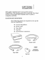
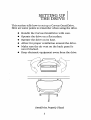
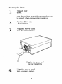
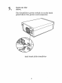
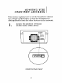
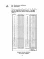
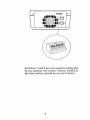
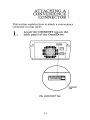
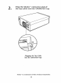
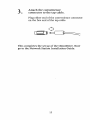
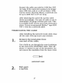
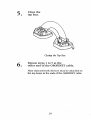
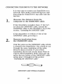
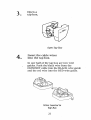
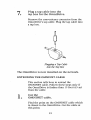
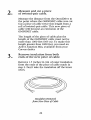
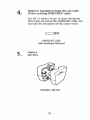
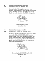
OmniDrive™
SETUP INSTRUCTIONS
OmniDrive™
SETUP INSTRUCTIONS
Pan Number: 7100-05257
Release Date: January 1984
Revision: A
OmniDrive'" is a trademark of Corvus Systems.
FCC WARNING
This equipment has been tested with a Class A computing device and has been
found to comply with Part 15 of FCC Rules. Operation in a residential area may
cause unacceptable interference to radio and TV reception requiring the operator to
take whatever steps are necessary to correct the interference.
NOTICE
Corvus Systems, Inc. reserves the right to make changes in the product described in
this manual at any time without notice. Revised manuals will be published as
needed and may be purchased from authorized Corvus Systems dealers.
This manual is copyrighted. All rights are reserved. This document may not in whole
or in part be copied, photocopied, reproduced, translated or reduced to any electronic
medium or machine readable form without prior consent, in writing, from:
Corvus Systems, Inc.
2100 CORVUS Drive
San Jose, CA 95124
Telephone: (408) 559-7000
TELEX: 278976
CopyrightC> 1984 by Corvus Systems, Inc.
The Corvus Concept," Transporter," OMNINET," LogiCalc," Time Travel Editing,"
EdWard," Constellation," Corvus," Corvus Systems," Personal Workstation," Tap
Box" and Passive Tap Box" are trademarks of Corvus Systems, Inc.
MIRRORI!> is a registered trademark of Corvus Systems, Inc. U.S. Patent 4,380,047.
TABLE OF
CONTENTS
Getting Started
Hardware Required
1
Setting up the Drive
2
Setting the OMNINET Address
7
Attaching the Convenience Connector
11
Setting up a Network
Laying Out the Cable
Terminating the Cable
Connecting the Drive to the Network
Extending the OMNINET Cable
15
1
iii
15
17
20
23
GETTING
STARTED
This guide explains how to set up the Corvus
. OmniDrive-the starting point for a network. The final
section of this guide also explains how to plan a
complete network.
HARDWARE REQUIRED
The following items are required to set up the
Corvus OmniDrive.
•
•
•
•
•
Corvus OmniDrive
Power cord
Tap cable
Tap Box
Convenience connector
OmniDrive
Power Cord
Connector
Convenience
Tap Cable
Tap box
I
2
SETTING UP
THE DRIVE
This section tells how to set up a Corvus OmniDrive.
Here are some points to remember when using the drive.
•
•
•
•
•
Handle the Corvus OmniDrive with care.
Operate the drive on a flat surface.
Operate the drive on its base.
Allow for proper ventilation around the drive.
Make sure the air vent on the back panel is
never blocked.
• I(eep electronic equipment away from the drive.
OmniDrive Properly Placed
3
To set up the drive:
1.
Unpack the
drive.
Save the packing materials because they can
be reused when transporting the drive.
2.
Put the drive on
a flat surface.
3.
Plug the power cord
into the OmniDrive.
Plugging the power cord
into the OmniDrive
4.
Plug the power cord
into a power outlet.
4
5.
Tum on the
drive.
The OmniDrive power switch is on the back
panel above the power cord connector.
Back Panel of the OmniDrive
5
When the drive is turned on, the three lights
on the front panel light up. After about twenty
seconds, only the READY light will stay lit
This means that the drive is ready for use. Go
to the next step.
If, after one minute, the READY light is not on
all by itself, reset the OmniDrive by turning it
off, then back on. If the READY light still does
not come on all by itself, go to the OmniDrive
Diagnostic Guide.
6.
Tum off
the drive.
6
SETTING THE
OMNINET ADDRESS
This section explains how to set the OmniDrive address
to a unique combination, so that the OmniDrive is
distinguishable from the other devices on the network
1.
Locate the address switches
on the back of the drive.
III~~II.
IIQOOOO~II
lE:]
II~OOOO~II ~o
Illiilll
(,IIIIIIIIEJ
12345678
OmniDrive Back Panel
7
•
2.
Set the device address
for the drive.
Choose an address from 0 to 63 for the drive.
Set the address on the switches. The table
below shows the switch settings for each
address.
Switch Setting
Address
Address
Switch Setting
1 2 3 4 5 6
0
1
2
3
4
5
6
7
8
9
10
11
12
13
14
15
16
17
18
19
20
21
22
23
24
25
26
27
28
29
30
31
i i i i i
-i i i i
1- j 1 i
- -1 1 i
1 i - 1 i
- i - i i
i - - i i
- - - i i
1 i i - 1
-i j - i
j i - i
- - j - i
i j- - j
- i- - j
j - - -'j
- - - -j
j
j
j
j -
j
j
j
j -
i -
i -
- - i i j-
i -
- i-
j -
i
i- - i - - - j j j
-j
i- j -
-
i -
i
-
1
-
1 - 1i- i- - - -
- - - -
i
1
1
1
i
1
i
j
1
j
j
j
i
i
j
j
j
j
j
j
j
j
j
j
j
j
1
1
1
1
1
1
1 2 3 4 5 6
i i i i ii i i jj i j j- -1 1 i 1 i - i i-
32
33
34
35
36
37
38
39
40
41
42
43
44
45
46
47
48
49
50
51
52
53
54
55
56
57
58
59
60
61
62
63
-
-1 - i
j - -1
- - -i
i i j -1 i i-
Switch Setting
j-
i-
1 2 3 4 5 6
Address
Switch Setting
1
-
= switch up
= switch down
Network Device Addresses
and Switch Settings
8
i-
- - i- j i j - - i - j - - jj - - - j - - - - j j j j j- j j j - j j j- - - j j - j i - j - -i - j - j - - j- - - - j - i j j - - -1 1 - - 1 - 1- - - - 1- - 1 j - - - - 1 - - - 1- - - - - - - - - -
1 2 3 4 5 6
Address
j-
iii -
li~~~~~~il OJ
II~OOOO~II ~o
Illiiilll
0
Switches 7 and 8 are not used for setting the
device address. Set switch 7 down. Switch 8,
the bias switch, should be on; set it down.
9
10
ATTACHING A
CONVENIENCE
CONNECTOR
This section explains how to attach a convenience
connector to a tap cable.
1.
Locate the OMNINET tap on the
back panel of the OmniDrive.
III~~III lE:5l
II~OOOO~II
II~OOOO~II ~o
Illiilll
The OMNINET Tap
11
2.
Plug the Molex™ connector end of
the tap cable into the OMNINET tap.
Plugging the Tap Cable
into the OMNINET Tap
Molex'" is a trademark of Molex Products Corporation.
12
3.
Attach the convenience
connector to the tap cable.
Plug either end of the convenience connector
on the free end of the tap cable.
This completes the set up of the OmniDrive. Now
go to the Network Station Installation Guide.
13
14
SETTING UP
ANETWORI(
This section tells how to plan an OMNINET network.
Before following these instructions, complete the System
Generation Guide.
LAYING OUT THE CABLE
The first step in planning an OMNINET
network is to design its layout The diagram
below shows what a simple OMNINET
network looks like.
Basic Network Configuration
15
Plan the layout of the OMNINET cable on
paper. A rough sketch or blueprint of the area
will help to decide where to run the cable.
D
[Ju[Ju[Ju
[Ju[Ju[Ju
]
D
-:Jl
IT
IT
IT
IT
~
=r
0
A Cable Plan for an Office Suite
There are two points to consider when planning
the cable layout First the cable has to come
within 15 feet (4.5 m) of every network device.
If a computer will be on top of a desk, be sure
that the cable runs near the desk. If a printer
or a Corvus drive will be in one comer of the
office, make sure that the cable runs through
that comer.
16
Second, the cable can only be 1000 feet 005
m) long. If the network is going to be longer
than 1000 feet, talk to a Corvus dealer. With
Corvus Active Junction Boxes, a network can
be up to 4000 feet (121 9 m) long.
After planning the network, put the cable
down accordingly. The type of cable to use is
unshielded, 20-gauge twisted-pair wire. This
is available from Corvus and most electronics
stores. Corvus recommends Belden type 8205
VW-l wire for a network cable.
TM
TERMINATING THE CABLE
After installing the network trunk cable close
off the ends with tap boxes and resistors.
1.
Remove the insulation from
one end of the cable.
Use a knife to cut through the outer insulation
at one end of the OMNINET cable. Take off
about 1.5 inches (4 cm) of the insulation. Do
not remove the insulation from the inner wires.
OMNINET Cable
2.
Pull apart
a tap box.
17
3.
Insert the cable wires
into the tap box.
In one half of the tap box are two wire guides.
Push the black wire from the OMNINET cable
into the BLACI( wire guide and the red wire
into the RED wire guide.
Cable Wires Inserted into the Tap Box
4.
Put a resistor
into the tap box.
Inside the other half of the tap box are two
metal pieces with notches in the side. Take
one of the Corvus supplied resistors and insert
one lead into each of the notches.
Resistor Inserted into
the Other Half of the Tap Box
18
5.
Close the
tap box.
Closing the Tap Box
6.
Repeat steps 1 to 5 at the
other end of the OMNINET cable.
Note that network devices may be attached to
the tap boxes at the ends of the OMNINET cable.
19
CONNECTING THE DRIVE TO THE NETWORK
It is very easy to connect an OmniDrive to a
network. First make a network tap box, and
then plug the OmniDrive's tap cable into the
tap box.
1.
Measure the distance from the
computer to the OMNINET cable.
If the OmniDrive is farther than 15 feet (4.5
m) from the OMNINET cable, extend the
OMNINET cable to the OmniDrive. Go to the
section, "Extending the OMNINET Cable."
If the OmniDrive is within 15 feet of the
OMNINET cable, go to step 2.
2.
Remove insulation from
the OMNINET cable.
Find the point on the OMNINET cable which
is closest to the OmniDrive. Use a knife to cut
through the outer insulation of the cable.
Remove about 2 inches (5 cm) of this
insulation, but do not cut the inner wires or
remove their insulation. If the wires are cut,
splice the two halves of the OMNINET cable
using step~ 5 through 8 of the section
"Extending the OMNINET Cable."
OMNINET Cable Without Insulation
20
3.
Open a
tap box.
Open Tap Box
4.
Insert the cable wires
into the tap box.
In one half of the tap box are two wire
guides. Push the black wire from the
OMNINET cable into the BLACI( wire guide
and the red wire into the RED wire guide.
Wires Inserted in
Tap Box
21
5.
Close the
tap box.
Make sure none of the red or black wire is
visible when the tap box is closed.
Closing the Tap Box
6.
Make sure the OmniDrive
is turned off. .
22
7.
Plug a tap cable into the
tap box for the OmniDrive.
Remove the convenience connector from the
OmniDrive's tap cable. Plug the tap cable into
a tap box.
Plugging a Tap Cable
into the Tap Box
The OmniDrive is now installed on the network.
EXTENDING THE OMNINET CABLE
This section tells how to extend the
OMNINET cable. Follow these steps only if
the OrnniDrive is farther than 15 feet (4.5 m)
from the cable.
1.
Cut the
OMNINET cable.
Find the point on the OMNINET cable which
is closest to the OmniDrive. Cut the cable at
this point
23
2.
Measure and cut a piece
of twisted-pair cable.
Measure the distance from the OmniDrive to
the point where the OMNINET cable was cut
Cut a piece of cable twice this length from a
roll of twisted-pair cable. This new piece of
cable will become an extension of the
OMNINET cable.
The length of the piece of cable plus the
length of the OMNINET cable must not be
more than 1000 feet 005 m). To make this
length greater than 1000 feet, you need an
Active Junction Box, available from your
Corvus dealer.
3.
Remove insulation from both
ends of the new piece of cable.
Remove 1.5 inches '(4 em) of outer insulation
from the ends of the piece of cable made in
step 2. Don't take the insulation off the inner
wires.
Insulation Removed
from New Piece of Cable
24
4.
Remove insulation from the cut ends
of the existing OMNINET cable.
Cut off 1.5 inches (4 em) of outer insulation
from each cut end of the OMNINET cable. Do
not take the insulation off the inner wires.
OMNINET Cable
with Insulation Removed
5.
Open a
tap box.
Opening a Tap Box
25
6.
Connect one end of the new
piece of cable to the tap box.
In one half of the tap box are two wire
guides. Push the black wire at one end of the
piece of cable into the BLACI( wire guide.
Push the red wire into the RED wire guide.
Connecting New Cable
to the Tap Box
7.
Connect a cut end of the
OMNINET cable'to the tap box.
Push the black and red wires from one of the
cut ends of the OMNINET cable into the
BLACI( and RED wire guides on top of the
wires from the cable piece. Make sure that
both red wires are together in the RED wire
guide and both black wires are together in
the BLACI( wire guide.
Connecting the OMNINET Cable End
to the Tap Box
26
8.
Close the
tap box.
Make sure none of the red or black wire is
visible when the tap box is closed.
Closing the Tap Box
27
9.
Repeat the
splicing procedure.
Use a second tap box and follow steps 5
through 8 for the remaining free ends of the
new piece of cable and the OMNINET cable.
When finished, a large loop in the OMNINET
cable will exist
~I
-----rr=
- - --
I
I
A Loop in the OMNINET Cable
10.
Go to step 2 of the section, Connecting
the Drive to a Network:'
II
28