1
Service Manual
DELTA 18-21-24
Indoor Units
Outdoor Units
DELTA 18
DELTA 21
GC 18
GC 22
OU7-24
OU7-24Z
DELTA 24
REFRIGERANT
COOLING ONLY
R410A
HEAT PUMP
SM DELTA 1-E.0 GB
JUNE – 2010
CONTENTS
LIST OF EFFECTIVE PAGES
LIST OF EFFECTIVE PAGES
Note: Changes in the pages are indicated by a “Revision#” in the footer of each effected page
(when none indicates no changes in the relevant page). All pages in the following list represent
effected/ non effected pages divided by chapters.
Dates of issue for original and changed pages are:
Original ....... 0 ........ JUNE 2010
Total number of pages in this publication is 93 consisting of the following:
Page
No.
Revision
No. #
Page
No.
Revision
No. #
Page
No.
Revision
No. #
Title ....................... 0
A ........................... 0
i ............................. 0
1-1 - 1-3 ................ 0
2-1 - 2-5 ................ 0
3-1 ........................ 0
4-1 - 4-2 ................ 0
5-1 - 5-12 .............. 0
6-1 - 6-5 ................ 0
7-1 ........................ 0
8-1 - 8-6 ................ 0
9-1 ........................ 0
10-1-10-4 .............. 0
11-1 ....................... 0
12-1-12-34 ............ 0
13-1-13-2 .............. 0
14-1-14-24 ............ 0
15-1-15-7 .............. 0
Appendix -A ...........0
• Zero in this column indicates an original page.
*Due to constant improvements please note that the data on this service manual can be modified with out notice.
**Photos are not contractual
A
CONTENTS
SM DELTA 1-E.0 GB
TABLE OF CONTENTS
Table of Contents
1.
INTRODUCTION ...................................................................................................1-1
2.
PRODUCT DATA SHEET ......................................................................................2-1
3.
RATING CONDITIONS ..........................................................................................3-1
4.
OUTLINE DIMENSIONS .......................................................................................4-1
5.
PERFORMANCE DATA & PRESSURE CURVES ................................................5-1
6.
SOUND LEVEL CHARACTERISTICS ..................................................................6-1
7.
ELECTRICAL DATA ..............................................................................................7-1
8.
WIRING DIAGRAMS .............................................................................................8-1
9.
ELECTRICAL CONNECTIONS .............................................................................9-1
10. REFRIGERATION DIAGRAMS .............................................................................10-1
11.
TUBING CONNECTIONS......................................................................................11-1
12. CONTROL SYSTEM .............................................................................................12-1
13. TROUBLESHOOTING ..........................................................................................13-1
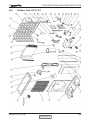
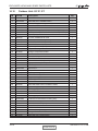
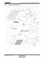
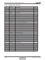
14. EXPLODED VIEWS AND SPARE PARTS LISTS .................................................14-1
15. OPTIONAL ACCESSORIES .................................................................................15-1
16. APPENDIX A .........................................................................................................16-1
SM DELTA 1-E.0 GB
i
INTRODUCTION
1.
INTRODUCTION
1.1
General
The new DELTA split wall mounted is based on the compact range. It comprise the ST
(cooling only) and RC (heat pump) models, as follows:
• Cooling Only: DELTA 18ST, DELTA 21ST, DELTA 24ST
• Heat Pump: DELTA 18RC, DELTA 21RC, DELTA 24RC
The indoor DELTA units are available as LED display types, featuring esthetic design,
compact dimensions, and low noise operation.
1.2
Main Features
The DELTA series benefits from the most advanced technological innovations, namely:
R410A refrigerant
Micro processor control.
Infrared remote control with LED display.
Indoor large diameter cross flow fan, allowing low operation sound level.
Bended Indoor coil with treated aluminum fins and coating for improved efficiency.
High COP.
Easy access to the interconnecting tubing and wiring connections.
Refrigerant pipes can be connected to the indoor unit from 5 different optional
directions.
The units are equipped.
Water condensate tray is equipped with two optional drain connections.
Automatic treated air sweep.
Low indoor noise levels.
Easy installation and service.
1.3
Indoor Unit
The indoor unit is wall mounted, and can be easily fitted to many types of residential and
commercials applications.
It includes:
Casing with air inlet and outlet grills.
A large-diameter tangential fan.
Bended coil with treated aluminum fins.
Motorized flaps.
3-speed motor with internal protection.
Advanced electronic control box assembly.
Interconnecting wiring terminal block.
Mounting plate.
SM DELTA 1-E.0 GB
CONTENTS
1-1
INTRODUCTION
1.4
Filtration
The DELTA series presents several types of air filters:
Easily accessible, and re-usable pre-filters (mesh).
Pre-charged electrostatic filter (diposable).
Active carbon filter (optional).
Active Electro Static re-usable filter (optional).
1.5
Control
The microprocessor indoor controller, and an infrared remote control, supplied as
standard, provide complete operating function and programming. For further details
please refer to the Operation Manual, Appendix A.
1.6
Outdoor Unit
The DELTA outdoor units can be installed as floor or wall mounted units by using a wall
supporting bracket. The metal sheets are protected by anti- corrosion paint work allowing
long life resistance. All outdoor units are pre-charged. For further information please
refer to the Product Data Sheet, Chapter 2.
It includes :
Axial fan.
Outdoor coil with hydrophilic louver fins for RC units.
Compressor mounted in a soundproofed compartment.
Outlet air fan grill.
Service valves” flare” type connection.
Interconnecting wiring terminal block.
1.7
Tubing Connections
Flare type interconnecting tubing can be produced on site.
For further details please refer to the Installation Manual, Chapter 11.
1.8
Accessories
ASK (All Season Kit):
For low ambient working conditions in cooling, an ASK can be installed inside the outdoor
unit. This kit allows cooling operation down to outdoor temp of -10 oC by gradually
controlling the outdoor fan speed motor.
RCW Wall Mounted Remote Control
The RCW remote control is mounted on the wall, and controls the unit either as an
infrared remote control or as a wired controller. The wired controller can control up to 10
Indoor units with the same program settings and adjustments.
For further details please refer to Optional Accessories, Chapter 15.
1.9
Inbox Documentation
Each unit is supplied with its own installation and operation manuals.
1-2
CONTENTS
SM DELTA 1-E.0 GB
INTRODUCTION
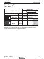
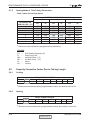
1.10
Matching Table
1.10.1
R410A
INDOOR UNITS
OUTDOOR UNITS
REFRIGER.
DELTA 18
GC 18 ST/RC
R410A
GC 22 ST/RC
R410A
GC 24 ST/RC
R410A
OU7-24
R410A
OU7-24Z
R410A
MODEL
DELTA 21
DELTA 24
The above table lists outdoor units and DELTA indoor units which can be matched together. In addition the
listed outdoor units can be matched with other types of indoor units such as cassettes, floor/ceiling.
For further information please refer to the relevant Service Manual.
SM DELTA 1-E.0 GB
CONTENTS
1-3
PRODUCT DATA SHEET
2.
PRODUCT DATA SHEET
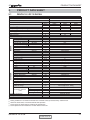
2.1
DELTA 18 / GC 18 R410A
Model Indoor Unit
Model Outdoor Unit
DELTA- 18
GC-18
Installation Method of Pipe
Characteristics
Capacity (4)
OUTDOOR
INDOOR
Power input (4)
EER (Cooling) or COP(Heating) (4)
Energy efficiency class
Power supply
Rated current
Starting current
Circuit breaker rating
Fan type & quantity
Fan speeds
H/M/L
Air flow (1)
H/M/L
External static pressure
Min-Max
Sound power level (2)
H/M/L
Sound pressure level (3)
H/M/L
Moisture removal
Condenstate drain tube I.D
Dimensions
WxHxD
Weight
Package dimensions
WxHxD
Packaged weight
Units per pallet
Stacking height
Refrigerant control
Compressor type,model
Fan type & quantity
Fan speeds
H/L
Air flow
H/L
Sound power level
H/L
Sound pressure level (3)
H/L
Dimensions
WxHxD
Weight
Package dimensions
WxHxD
Packaged weight
Units per pallet
Stacking height
Refrigerant type
Refrigerant chargless distance
Additional charge
Connections between
units
Operation control type
Heating elements
Others
(1)
(2)
(3)
(4)
Flared
Cooling Only
Cooling
Heating
18250
18250
18420
5.35
5.35
5.40
1.66
1.66
1.56
3.22
3.22
3.46
A
A
B
V/Hz/Ph
220-240V/50Hz/Single
A
7.5
7
7.1
A
43
A
15
Cross flow*1
RPM
1200/1100/1000
m3/hr
930/840/750
Pa
N/A
dB(A)
56/53/50
dB(A)
43/40/37
l/hr
1.8
mm
16
mm
1060/295/210
kg
14
mm
1115/350/260
kg
17
units
16
units
8
Capillary tube
Rotary,TOSHIBA PA200X2CS-4KU1
Propeller(direct) x 1
RPM
815
m3/hr
2480
dB(A)
68
dB(A)
57
mm
846/302/690
kg
56
mm
990/430/770
kg
61
Units
9
units
3
R410A
kg/m
1.54kg/7.5m
4mLength10m 1540g 10mLength18m 1690g
g/m
18mLength25m 1900g
In.(mm)
1/4"(6.35)
In.(mm)
1/2"(12.7)
m.
25
m.
15
Remote control
kW
All season kit Factory option
Units
Btu/hr
kW
kW
W/W
Liquid line
Suction line
Max.tubing length
Max.height difference
Rating conditions in accordance with ISO 5151 and ISO 13253 (for ducted units). and EN 14511
Airflow in ducted units; at nominal external static pressure.
Sound power in ducted units is measured at air discharge.
Sound pressure level measured at 1 meter distance from unit.
SM DELTA 1-E.0 GB
CONTENTS
2-1
PRODUCT DATA SHEET
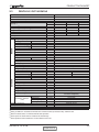
2.2
DELTA 21 / GC 22 R410A
Model Indoor Unit
Model Outdoor Unit
DELTA- 21
GC-22
Installation Method of Pipe
Characteristics
Units
Btu/hr
kW
kW
W/W
Capacity (4)
Power input (4)
EER (Cooling) or COP(Heating) (4)
Energy efficiency class
Power supply
Rated current
Starting current
Circuit breaker rating
Fan type & quantity
Fan speeds
H/M/L
H/M/L
Air flow (1)
External static pressure
Min-Max
H/M/L
Sound power level (2)
Sound pressure level (3)
H/M/L
Moisture removal
Condenstate drain tube I.D
Dimensions
WxHxD
Weight
Package dimensions
WxHxD
Packaged weight
Units per pallet
Stacking height
Refrigerant control
Compressor type,model
Fan type & quantity
Fan speeds
H/L
Air flow
H/L
Sound power level
H/L
H/L
Sound pressure level (3)
Dimensions
WxHxD
Weight
Package dimensions
WxHxD
Packaged weight
Units per pallet
Stacking height
Refrigerant type
Refrigerant chargless distance
V/Hz/Ph
A
A
A
INDOOR
RPM
m3/hr
Pa
dB(A)
dB(A)
l/hr
mm
mm
kg
mm
kg
units
units
OUTDOOR
RPM
m3/hr
dB(A)
dB(A)
mm
kg
mm
kg
Units
units
kg/m
Additional charge
Connections between
units
Operation control type
Heating elements
Others
g/m
Liquid line
Suction line
Max.tubing length
Max.height difference
In.(mm)
In.(mm)
m.
m.
kW
Flared
Cooling Only
Cooling
Heating
21150
21150
22180
6.2
6.2
6.50
2.05
2.05
2.00
3.02
3.02
3.25
B
B
C
220-240V/50Hz/Single
9.3
9.3
9.7
50
20
Cross flow*1
1300/1200/1100
910/820/740
0
60/57/55
47/44/42
2.3
16
1060x295x210
15
1125x360x280
18
16
8
Capillary tube
Rotary,TOSHIBA PA240X2CS-4KU1
Propeller(direct) x 1
815
2860
69
59
846/302/690
56
990/720/430
61
9
3 levels
R410A
2.0kg/7.5m
4mLength10m:+0g;
10mLength15m:+330g;
15mLength20m:+460g
3/8"(9.53)
5/8"(15.88)
Max 20
Max 15
Remote control
1.65/0.9
(1)
Rating conditions in accordance with ISO 5151 and ISO 13253 (for ducted units). and EN 14511
Airflow in ducted units; at nominal external static pressure.
(3)
Sound power in ducted units is measured at air discharge.
(4)
Sound pressure level measured at 1 meter distance from unit.
(2)
2-2
CONTENTS
SM DELTA 1-E.0 GB
PRODUCT DATA SHEET
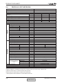
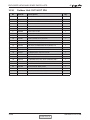
2.3
DELTA 24 / OU7-24 R410A
Model Indoor Unit
Model Outdoor Unit
DELTA- 24
OU7-24
Installation Method of Pipe
Characteristics
Units
Btu/hr
kW
kW
W/W
Capacity (4)
Power input (4)
EER (Cooling) or COP(Heating) (4)
Energy efficiency class
Power supply
Rated current
Starting current
Circuit breaker rating
Fan type & quantity
Fan speeds
H/M/L
H/M/L
Air flow (1)
External static pressure
Min-Max
H/M/L
Sound power level (2)
Sound pressure level (3)
H/M/L
Moisture removal
Condenstate drain tube I.D
Dimensions
WxHxD
Weight
Package dimensions
WxHxD
Packaged weight
Units per pallet
Stacking height
Refrigerant control
Compressor type,model
Fan type & quantity
Fan speeds
H/L
Air flow
H/L
Sound power level
H/L
H/L
Sound pressure level (3)
Dimensions
WxHxD
Weight
Package dimensions
WxHxD
Packaged weight
Units per pallet
Stacking height
Refrigerant type
Refrigerant chargless distance
V/Hz/Ph
A
A
A
INDOOR
RPM
m3/hr
Pa
dB(A)
dB(A)
l/hr
mm
mm
kg
mm
kg
units
units
OUTDOOR
RPM
m3/hr
dB(A)
dB(A)
mm
kg
mm
kg
Units
units
kg/m
Additional charge
Connections between
units
Operation control type
Heating elements
Others
g/m
Liquid line
Suction line
Max.tubing length
Max.height difference
In.(mm)
In.(mm)
m.
m.
Flared
Cooling Only
Cooling
Heating
23100
23100
24150
6.77
6.77
7.08
2.24
2.24
2.35
3.02
3.02
2.95
B
B
D
220-240V/50Hz/Single
10.5
10.5
11.0
63
20
Cross flow*1
1300/1200/1100
910/820/740
N/A
60/57/55
47/44/42
2.3
16
1060x295x210
15
1125x360x280
18
16
8
Capillary tube
Rotary
AXIAL*1
850
720
3100
2600
67
62
58
54
900/680/340
74
985/730/406
77
6
2 levels
R410A
2.035kg/12.5m
12.5m<dd 350g<15m;
15m<dd 1040g<20m;
3/8"(9.53)
5/8"(15.88)
Max 20
Max 15
Remote control
kW
All season kit Factory option
(1)
Rating conditions in accordance with ISO 5151 and ISO 13253 (for ducted units). and EN 14511
Airflow in ducted units; at nominal external static pressure.
(3)
Sound power in ducted units is measured at air discharge.
(4)
Sound pressure level measured at 1 meter distance from unit.
(2)
SM DELTA 1-E.0 GB
CONTENTS
2-3
PRODUCT DATA SHEET
2.4
DELTA 24 / OU7-24Z R410A
Model Indoor Unit
Model Outdoor Unit
DELTA- 24
OU7-24Z
Installation Method of Pipe
Characteristics
Units
Btu/hr
kW
kW
W/W
Capacity (4)
Power input (4)
EER (Cooling) or COP(Heating) (4)
Energy efficiency class
Power supply
Rated current
Starting current
Circuit breaker rating
Fan type & quantity
Fan speeds
H/M/L
H/M/L
Air flow (1)
External static pressure
Min-Max
H/M/L
Sound power level (2)
H/M/L
Sound pressure level (3)
Moisture removal
Condenstate drain tube I.D
Dimensions
WxHxD
Weight
Package dimensions
WxHxD
Packaged weight
Units per pallet
Stacking height
Refrigerant control
Compressor type,model
Fan type & quantity
Fan speeds
H/L
Air flow
H/L
Sound power level
H/L
H/L
Sound pressure level (3)
Dimensions
WxHxD
Weight
Package dimensions
WxHxD
Packaged weight
Units per pallet
Stacking height
Refrigerant type
Refrigerant chargless distance
V/Hz/Ph
A
A
A
INDOOR
RPM
m3/hr
Pa
dB(A)
dB(A)
l/hr
mm
mm
kg
mm
kg
units
units
OUTDOOR
RPM
m3/hr
dB(A)
dB(A)
mm
kg
mm
kg
Units
units
kg/m
Additional charge
Connections between
units
Operation control type
Heating elements
Others
Liquid line
Suction line
Max.tubing length
Max.height difference
Flared
Cooling Only
Cooling
Heating
23100
23100
24150
6.77
6.77
7.08
2.24
2.24
2.35
3.02
3.02
2.95
B
B
D
220-240V/50Hz/Single
10.5
10.5
11.0
63
20
Cross flow*1
1300/1200/1100
910/820/740
N/A
60/57/55
47/44/42
2.3
16
1060x295x210
15
1125x360x280
18
16
8
Capillary tube
Rotary
AXIAL*1
850
720
3100
2600
67
62
58
54
900/680/340
64
985/730/406
67
6
2 levels
R410A
1.7kg / 7.5m
g/m
7.5m<dd 30g / <15m;
In.(mm)
In.(mm)
m.
m.
3/8"(9.53)
5/8"(15.88)
Max 15
Max 7
LCD Remote control
kW
(1)
Rating conditions in accordance with ISO 5151 and ISO 13253 (for ducted units). and EN 14511
Airflow in ducted units; at nominal external static pressure.
(3)
Sound power in ducted units is measured at air discharge.
(4)
Sound pressure level measured at 1 meter distance from unit.
(2)
2-4
CONTENTS
SM DELTA 1-E.0 GB
PRODUCT DATA SHEET
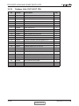
2.4
DELTA 24 / OU7-24T R410A
Model Indoor Unit
Model Outdoor Unit
DELTA- 24
OU7-24T
Installation Method of Pipe
Characteristics
Capacity
Units
Btu/hr
kW
kW
W/W
(4)
Power input (4)
EER (Cooling) or COP(Heating) (4)
Energy efficiency class
Power supply
Rated current
Starting current
Circuit breaker rating
Fan type & quantity
Fan speeds
H/M/L
H/M/L
Air flow (1)
External static pressure
Min-Max
H/M/L
Sound power level (2)
H/M/L
Sound pressure level (3)
Moisture removal
Condenstate drain tube I.D
Dimensions
WxHxD
Weight
Package dimensions
WxHxD
Packaged weight
Units per pallet
Stacking height
Refrigerant control
Compressor type,model
Fan type & quantity
Fan speeds
H/L
Air flow
H/L
Sound power level
H/L
H/L
Sound pressure level (3)
Dimensions
WxHxD
Weight
Package dimensions
WxHxD
Packaged weight
Units per pallet
Stacking height
Refrigerant type
Refrigerant chargless distance
V/Hz/Ph
A
A
A
INDOOR
RPM
m3/hr
dB(A)
dB(A)
mm
kg
mm
kg
Units
units
OUTDOOR
Operation control type
Heating elements
Others
4.1×3
RPM
m3/hr
Pa
dB(A)
dB(A)
l/hr
mm
mm
kg
mm
kg
units
units
kg/m
Additional charge
Connections between
units
Cooling Only
23220
6.81
2.26
3.02
B
g/m
Liquid line
Suction line
Max.tubing length
Max.height difference
In.(mm)
In.(mm)
m.
m.
Flared
Cooling
23220
6.81
2.26
3.02
B
400V/50Hz/3N
4.1×3
55
10×3
Cross flow*1
1300/1200/1100
990/930/840
N/A
58/55/53
45/42/40
2.3
16
1060/295/210
15
1115/350/260
18
16
8
Capillary tube
Rotary
AXIAL*1
850
3100
67
58
Heating
25130
7.37
2.4
3.07
D
4.4×3
720
2600
62
54
900/680/340
74
985/730/406
74
6
2 levels
R410A
2.035kg / 12.5m
12.5m<dd 350g <15m;
12.5m<Add 1040g<20m
3/8"(9.53)
5/8"(15.88)
Max 20
Max 15
LCD Remote control
kW
All season kit Factory option
(1)
Rating conditions in accordance with ISO 5151 and ISO 13253 (for ducted units). and EN 14511
Airflow in ducted units; at nominal external static pressure.
(3)
Sound power in ducted units is measured at air discharge.
(4)
Sound pressure level measured at 1 meter distance from unit.
(2)
SM DELTA 1-E.0 GB
CONTENTS
2-5
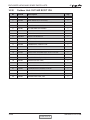
RATING CONDITIONS
3.
RATING CONDITIONS
Standard conditions in accordance with ISO 5151, ISO 13253 (for ducted units)
and EN 14511.
Cooling:
Indoor:
27oC DB 19oC WB
Outdoor: 35 oC DB
Heating:
Indoor:
20oC DB
Outdoor: 7oC DB 6oC WB
3.1
Operating Limits
3.1.1 R410A
Indoor
Cooling
Heating
Voltage
SM DELTA 1-E.0 GB
Upper limit
Lower limit
Upper limit
Lower limit
Outdoor
32oC DB 23oC WB
21oC DB 15oC WB
27oC DB
20oC DB
46oC DB
21oC DB
24oC DB 18oC WB
-9oC DB -10oC WB
1PH
198 – 264 V
3PH
360 – 440 V
CONTENTS
3-1
OUTLINE DIMENSIONS
4.
OUTLINE DIMENSIONS
4.1
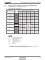
Indoor Unit: DELTA 18, 21, 24
4.2
Outdoor Unit: GC 18, 22
SM DELTA 1-E.0 GB
CONTENTS
4-1
OUTLINE DIMENSIONS
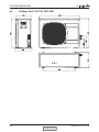
4.3
4-2
Outdoor Unit: OU7-24, OU7-24Z
CONTENTS
SM DELTA 1-E.0 GB
PERFORMANCE DATA & PRESSURE CURVES
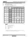
5.
PERFORMANCE DATA & PRESSURE CURVES
5.1
DELTA18 GC18 R410A
5.1.1
Cooling Mode at 7.5m Tubing Connection.
230V : Indoor Fan at High Speed.
ENTERING AIR
DB OU COIL (°C)
15
(1)
20(1)
25
30
ENTERING AIR WB/DB ID COIL ( °C)
DATA
15/21
17/24
19/27
21/29
23/32
TC
5.64
5.84
5.98
6.12
6.21
SC
3.87
4.03
4.19
4.30
4.38
PI
TC
SC
PI
TC
SC
PI
TC
SC
PI
1.18
5.46
3.79
1.28
5.16
3.69
1.38
4.83
3.58
1.49
4.47
3.40
1.61
4.06
3.21
1.73
3.53
2.95
1.89
1.18
5.75
4.00
1.28
5.57
3.92
1.39
5.26
3.80
1.51
4.85
3.65
1.63
4.42
3.45
1.76
3.86
3.16
1.92
1.18
5.93
4.17
1.29
5.86
4.13
1.40
5.68
4.04
1.52
1.18
6.07
4.28
1.29
6.04
4.25
1.41
5.88
4.16
1.54
5.62
4.06
1.67
5.28
3.86
1.81
4.68
3.53
1.99
1.19
6.20
4.36
1.30
6.18
4.33
1.42
6.05
4.24
1.55
5.88
4.14
1.68
5.55
3.93
1.83
5.05
3.60
2.02
TC
35
SC
PI
TC
40
SC
PI
TC
SC
46
PI
5.35
3.95
1.66
4.83
3.74
1.79
4.24
3.41
1.97
LEGEND
TC
SC
PI
WB
DB
ID
OU
–
–
–
–
–
–
–
Total Cooling Capacity, kW
Sensible Capacity, kW
Power Input, kW
Wet Bulb Temp., (oC)
Dry Bulb Temp., (oC)
Indoor
Outdoor
(1) Marked area is below standard operating limits. For operating in low ambient
conditions, refer to Optional Accessories (Chapter 15).
SM DELTA 1-E.0 GB
CONTENTS
5-1
PERFORMANCE DATA & PRESSURE CURVES
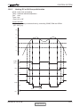
5.1.2
Heating Mode at 7.5m Tubing Connection.
230V : Indoor Fan at High Speed.
ENTERING AIR DB ID COIL ( °C)
20
15
ENTERING AIR
WB OU COIL ( °C)
-10
-7
-2
2
6
10
15
20
25
TH
PI
TH
PI
TH
PI
2.84
3.05
3.24
3.94
5.56
6.05
6.53
6.89
1.25
1.28
1.29
1.36
1.46
1.54
1.61
1.65
2.73
2.94
3.13
3.78
5.40
5.89
6.37
6.72
1.33
1.35
1.37
1.44
1.56
1.65
1.73
1.79
2.62
2.84
3.02
3.62
5.21
5.72
6.21
6.53
1.40
1.42
1.45
1.53
1.66
1.76
1.84
1.93
* the above chart includes the weighted deicing infleuence.
LEGEND
TH
PI
WB
DB
ID
OU
5.2
5.2.1
–
–
–
–
–
–
Total Heating Capacity, kW
Power Input, kW
Wet Bulb Temp., (oC)
Dry Bulb Temp., (oC)
Indoor
Outdoor
Capacity Correction Factor Due to Tubing Length
Cooling
3m
1.02
7.5m
1
10m
0.99
TOTAL TUBING LENGTH
15m
20m
25m
0.975
0.965
0.950
30m
---
40m
---
50m
---
* Minimum recommended tubing length between indoor and outdoor units is 3m.
5.2.2
Heating
3m
1.05
7.5m
1
10m
1
TOTAL TUBING LENGTH
15m
20m
25m
0.993
0.988
0.978
30m
---
40m
---
50m
---
* Minimum recommended tubing length between indoor and outdoor units is 3m.
5-2
CONTENTS
SM DELTA 1-E.0 GB
PERFORMANCE DATA & PRESSURE CURVES
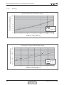
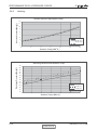
5.3
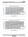
Pressure Curves.
5.3.1
Cooling.
Suction Pressure VS.Outdoor Temp
12.0
15/21(WB/DB
17/24(WB/DB
19/27(WB/DB
21/29(WB/DB
23/32(WB/DB
Suction Pressure (Bar[g])
11.5
11.0
10.5
10.0
ºC)
ºC)
ºC)
ºC)
ºC)
9.5
9.0
8.5
8.0
7.5
7.0
6.5
6.0
15
20
25
30
35
40
46
40
46
o
Outdoor Temp.(DB C )
Discharge Pressure (Bar[g])
Discharge Pressure VS.Outdoor Temp
40
38
36
34
32
30
28
26
24
22
20
18
16
14
12
10
15/21(WB/DB
17/24(WB/DB
19/27(WB/DB
21/29(WB/DB
23/32(WB/DB
15
20
ºC)
ºC)
ºC)
ºC)
ºC)
25
30
35
o
Outdoor Temp.(DB C )
SM DELTA 1-E.0 GB
CONTENTS
5-3
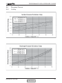
PERFORMANCE DATA & PRESSURE CURVES
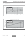
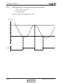
5.3.2
Heating.
Suction Pressure VS.Outdoor Temp
Suction Pressure(Bar[g])
12.0
11.0
10.0
9.0
8.0
7.0
15 DB (ºC)
6.0
20 DB (ºC)
5.0
25 DB (ºC)
4.0
3.0
-10
-5
0
5
10
15
20
o
Outdoor Temp.( WB C )
Discharge Pressure VS.Outdoor Temp
Discharge Pressure(Bar[g])
36
34
32
30
28
26
24
22
25 DB (ºC)
20
20 DB (ºC)
18
15 DB (ºC)
16
14
-10
-5
0
5
o
10
15
20
Outdoor Temp.( WB C )
5-4
CONTENTS
SM DELTA 1-E.0 GB
PERFORMANCE DATA & PRESSURE CURVES
5.4
5.4.1
DELTA21 GC21 R410A
Cooling Mode at 7.5m Tubing Connection.
230V : Indoor Fan at High Speed.
ENTERING AIR
DB OU COIL (°C)
15
ENTERING AIR WB/DB ID COIL ( °C)
DATA
TC
SC
PI
TC
SC
PI
TC
SC
PI
TC
SC
PI
TC
SC
PI
TC
SC
PI
TC
SC
PI
(1)
20(1)
25
30
35
40
46
15/21
17/24
19/27
21/29
23/32
6.53
4.45
1.45
6.32
4.36
1.58
5.98
4.25
1.71
5.59
4.11
1.84
5.18
3.91
1.98
4.71
3.69
2.14
4.09
3.40
2.34
6.77
4.64
1.46
6.66
4.59
1.58
6.46
4.51
1.72
6.09
4.37
1.87
5.62
4.19
2.02
5.13
3.97
2.17
4.47
3.64
2.37
6.93
4.82
1.46
6.87
4.79
1.59
6.79
4.75
1.73
6.58
4.65
1.88
6.20
4.54
2.05
5.59
4.29
2.21
4.91
3.92
2.43
7.09
4.94
1.46
7.04
4.92
1.60
7.00
4.89
1.74
6.81
4.78
1.90
6.51
4.67
2.07
6.12
4.43
2.24
5.43
4.05
2.46
7.20
5.03
1.47
7.19
5.01
1.60
7.17
4.98
1.75
7.02
4.87
1.91
6.82
4.76
2.08
6.43
4.52
2.26
5.85
4.14
2.49
LEGEND
TC
SC
PI
WB
DB
ID
OU
–
–
–
–
–
–
–
Total Cooling Capacity, kW
Sensible Capacity, kW
Power Input, kW
Wet Bulb Temp., (oC)
Dry Bulb Temp., (oC)
Indoor
Outdoor
(1) Marked area is below standard operating limits. For operating in low ambient
conditions, refer to Optional Accessories (Chapter 15).
SM DELTA 1-E.0 GB
CONTENTS
5-5
PERFORMANCE DATA & PRESSURE CURVES
5.4.2
Heating Mode at 7.5m Tubing Connection.
230V : Indoor Fan at High Speed.
ENTERING AIR DB ID COIL ( °C)
15
20
25
ENTERING AIR
WB OU COIL ( °C)
TH
PI
TH
PI
TH
PI
-10
-7
-2
2
6
10
15
20
3.41
3.67
3.90
4.75
6.70
7.28
7.87
8.29
1.60
1.64
1.66
1.74
1.87
1.97
2.06
2.12
3.28
3.54
3.77
4.55
1.70
1.73
1.76
1.85
6.50
2.00
7.09
7.67
8.09
2.11
2.22
2.30
3.15
3.41
3.64
4.36
6.27
6.89
7.48
7.87
1.79
1.82
1.86
1.96
2.12
2.26
2.36
2.48
* the above chart includes the weighted deicing infleuence.
LEGEND
TH
PI
WB
DB
ID
OU
–
–
–
–
–
–
Total Heating Capacity, kW
Power Input, kW
Wet Bulb Temp., (oC)
Dry Bulb Temp., (oC)
Indoor
Outdoor
5.5
Capacity Correction Factor Due to Tubing Length
5.5.1
Cooling
3m
1.02
7.5m
1
TOTAL TUBING LENGTH
10m
15m
20m 25m 30m
0.961
0.950
-------
40m
---
50m
---
* Minimum recommended tubing length between indoor and outdoor units is 3m.
5.5.2
Heating
3m
1.04
7.5m
1
TOTAL TUBING LENGTH
10m
15m
20m 25m 30m
0.975
0.961
-------
40m
---
50m
---
* Minimum recommended tubing length between indoor and outdoor units is 3m.
5-6
CONTENTS
SM DELTA 1-E.0 GB
PERFORMANCE DATA & PRESSURE CURVES
5.6
Pressure Curves.
5.6.1
Cooling.
SM DELTA 1-E.0 GB
CONTENTS
5-7
PERFORMANCE DATA & PRESSURE CURVES
5.6.2
5-8
Heating.
CONTENTS
SM DELTA 1-E.0 GB
PERFORMANCE DATA & PRESSURE CURVES
5.7
DELTA24 / OU7- 24, DELTA24 / OU7-24Z 1PH/3PH R410A
5.7.1
Cooling Mode at 7.5m Tubing Connection.
230V : Indoor Fan at High Speed.
ENTERING AIR
DB OU COIL (°C)
15
ENTERING AIR WB/DB ID COIL ( °C)
DATA
TC
SC
PI
TC
SC
PI
TC
SC
PI
TC
SC
PI
TC
SC
PI
TC
SC
PI
TC
SC
PI
(1)
20(1)
25
30
35
40
46
15/21
17/24
19/27
21/29
23/32
7.14
4.80
1.59
6.90
4.70
1.72
6.53
4.58
1.86
6.11
4.44
2.01
5.66
4.22
2.17
5.14
3.98
2.34
4.46
3.66
2.55
7.39
5.00
1.59
7.28
4.96
1.73
7.05
4.86
1.88
6.65
4.72
2.04
6.14
4.52
2.20
5.60
4.28
2.37
4.88
3.93
2.59
7.57
5.20
1.59
7.51
5.17
1.74
7.42
5.13
1.89
7.19
5.02
2.06
6.77
4.90
2.24
6.11
4.64
2.41
5.37
4.23
2.65
7.74
5.33
1.60
7.68
5.31
1.75
7.64
5.28
1.90
7.44
5.16
2.07
7.11
5.04
2.26
6.68
4.78
2.44
5.93
4.37
2.69
7.86
5.43
1.61
7.85
5.41
1.75
7.83
5.37
1.91
7.66
5.26
2.09
7.45
5.14
2.27
7.02
4.88
2.47
6.39
4.47
2.72
LEGEND
TC
SC
PI
WB
DB
ID
OU
–
–
–
–
–
–
–
Total Cooling Capacity, kW
Sensible Capacity, kW
Power Input, kW
Wet Bulb Temp., (oC)
Dry Bulb Temp., (oC)
Indoor
Outdoor
(1) Marked area is below standard operating limits. For operating in low ambient
conditions, refer to Optional Accessories (Chapter 15).
SM DELTA 1-E.0 GB
CONTENTS
5-9
PERFORMANCE DATA & PRESSURE CURVES
5.7.2
Heating Mode at 7.5m Tubing Connection.
230V : Indoor Fan at High Speed.
ENTERING AIR DB ID COIL ( °C)
20
15
ENTERING AIR
WB OU COIL ( °C)
-10
-7
-2
2
6
10
15
20
25
TH
PI
TH
PI
TH
PI
3.72
4.00
4.25
5.17
7.29
7.93
8.57
9.03
1.88
1.93
1.95
2.04
2.20
2.32
2.42
2.49
3.58
3.86
4.11
4.96
2.00
2.03
2.07
2.17
7.08
2.35
7.72
8.35
8.81
2.48
2.61
2.70
3.43
3.72
3.96
4.74
6.83
7.50
8.14
8.57
2.10
2.14
2.19
2.30
2.50
2.65
2.77
2.91
* the above chart includes the weighted deicing infleuence.
LEGEND
TH
PI
WB
DB
ID
OU
–
–
–
–
–
–
Total Heating Capacity, kW
Power Input, kW
Wet Bulb Temp., (oC)
Dry Bulb Temp., (oC)
Indoor
Outdoor
5.8
Capacity Correction Factor Due to Tubing Length
5.8.1
Cooling
3m
1.01
7.5m
1
TOTAL TUBING LENGTH
10m
15m
20m
25m
0.980
0.970
0.960
---
30m
---
40m
---
50m
---
* Minimum recommended tubing length between indoor and outdoor units is 3m.
5.8.2
Heating
3m
1.02
7.5m
1
TOTAL TUBING LENGTH
10m
15m
20m
25m
0.990
0.990
0.980
---
30m
---
40m
---
50m
---
* Minimum recommended tubing length between indoor and outdoor units is 3m.
5-10
CONTENTS
SM DELTA 1-E.0 GB
PERFORMANCE DATA & PRESSURE CURVES
5.9
Pressure Curves.
5.9.1
Cooling.
Suction Pressure VS.Outdoor Temp
Suction Pressure (Bar[g])
12
21/15(DB/WB
24/17(DB/WB
27/19(DB/WB
29/21(DB/WB
32/23(DB/WB
11
10
ºC)
ºC)
ºC)
ºC)
ºC)
9
8
7
6
5
15
20
25
30
35
40
46
40
46
o
Outdoor Temp.(DB C )
Discharge Pressure (Barg])
Discharge Pressure VS.Outdoor Temp
40
38
36
34
32
30
28
26
24
22
20
18
16
14
21/15(DB/WB
24/17(DB/WB
27/19(DB/WB
29/21(DB/WB
32/23(DB/WB
15
20
ºC)
ºC)
ºC)
ºC)
ºC)
25
30
35
o
Outdoor Temp.(DB C )
SM DELTA 1-E.0 GB
CONTENTS
5-11
PERFORMANCE DATA & PRESSURE CURVES
5.9.2
Heating.
Suction Pressure VS.Outdoor Temp
Suction Pressure(Bar[g])
12
11
10
9
8
7
6
15 DB (ºC)
5
20 DB (ºC)
4
25 DB (ºC)
3
-10
-5
0
5
10
15
20
o
Outdoor Temp.( WB C )
Discharge Pressure(Bar[g])
Discharge Pressure VS.Outdoor Temp
40
38
36
34
32
30
28
26
24
22
20
18
16
14
25 DB (ºC)
20 DB (ºC)
15 DB (ºC)
-10
-5
0
5
10
15
20
o
Outdoor Temp.( WB C )
5-12
CONTENTS
SM DELTA 1-E.0 GB
SOUND LEVEL CHARACTERISTICS
6.
SOUND LEVEL CHARACTERISTICS
6.1
Sound Pressure Level
Unit
1m
Wall
0.8m
FAN SPEED
LINE
HI
Mic.
ME
LO
Figure 1
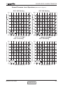
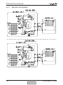
6.2
Sound Pressure Level Spectrum (Measured as Figure 1)
DELTA 21
NC-70
NC-60
NC-50
NC-40
NC-30
APPROXIMATE
THRESHOLD OF
HEARING FOR
CONTINUOUS
NOISE
NC-20
OCTAVE BAND SOUND PRESSURE LEVEL, dB re 0.002 MICRO BAR
OCTAVE BAND SOUND PRESSURE LEVEL, dB re 0.002 MICRO BAR
DELTA 18
BAND CENTER FREQUENCIES, Hz
NC-70
NC-60
NC-50
NC-40
NC-30
APPROXIMATE
THRESHOLD OF
HEARING FOR
CONTINUOUS
NOISE
NC-20
BAND CENTER FREQUENCIES, Hz
DELTA 24
SM DELTA 1-E.0 GB
CONTENTS
6-1
SOUND LEVEL CHARACTERISTICS
6.3
Outdoor units
Unit
1m
Mic.
Ground
Figure 2
6.4
Sound Pressure Level Spectrum (Measured as Figure 2)
GC 18 Heating
NC-70
NC-60
NC-50
NC-40
NC-30
APPROXIMATE
THRESHOLD OF
HEARING FOR
CONTINUOUS
NOISE
NC-20
OCTAVE BAND SOUND PRESSURE LEVEL, dB re 0.002 MICRO BAR
OCTAVE BAND SOUND PRESSURE LEVEL, dB re 0.002 MICRO BAR
GC 18 Cooling
NC-70
NC-60
NC-50
NC-40
NC-30
APPROXIMATE
THRESHOLD OF
HEARING FOR
CONTINUOUS
NOISE
BAND CENTER FREQUENCIES, Hz
BAND CENTER FREQUENCIES, Hz
GC 22 Heating
NC-70
NC-60
NC-50
NC-40
NC-30
NC-20
OCTAVE BAND SOUND PRESSURE LEVEL, dB re 0.002 MICRO BAR
OCTAVE BAND SOUND PRESSURE LEVEL, dB re 0.002 MICRO BAR
GC 22 Cooling
APPROXIMATE
THRESHOLD OF
HEARING FOR
CONTINUOUS
NOISE
BAND CENTER FREQUENCIES, Hz
6-2
NC-20
NC-70
NC-60
NC-50
NC-40
NC-30
APPROXIMATE
THRESHOLD OF
HEARING FOR
CONTINUOUS
NOISE
NC-20
BAND CENTER FREQUENCIES, Hz
CONTENTS
SM DELTA 1-E.0 GB
SOUND LEVEL CHARACTERISTICS
OU7- 24 Z Cooling
OU7- 24Z Heating
OU7- 24 Cooling
OU7- 24 Heating
NC-70
NC-60
NC-50
NC-40
NC-30
APPROXIMATE
THRESHOLD OF
HEARING FOR
CONTINUOUS
NOISE
NC-20
OCTAVE BAND SOUND PRESSURE LEVEL, dB re 0.002 MICRO BAR
OCTAVE BAND SOUND PRESSURE LEVEL, dB re 0.002 MICRO BAR
Sound Pressure Level Spectrum (Measured as Figure 2)
NC-70
NC-60
NC-50
NC-40
NC-30
APPROXIMATE
THRESHOLD OF
HEARING FOR
CONTINUOUS
NOISE
NC-20
BAND CENTER FREQUENCIES, Hz
BAND CENTER FREQUENCIES, Hz
SM DELTA 1-E.0 GB
CONTENTS
6-3
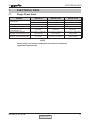
ELECTRICAL DATA
7.
ELECTRICAL DATA
7.1
Single Phase Units
MODEL
Power Supply
Max Current, A
Circuit Breaker,A
Power Supply Wiring No. X
Cross Section mm2
Interconnecting Cable RC
Model No. X Cross Section mm2
Interconnecting Cable ST
Model No. X Cross Section mm2
DELTA 18
DELTA 21/24
DELTA 21/24
To indoor
To Outdoor
To Outdoor
1PH-230V-50Hz
1PH-230V-50Hz
3PH-400V-50Hz
11.1
14
3×6
15
20
3×10
3×1.5 mm2
3×2.5 mm2
5×1.5 mm2
5×1.5 mm2 + 2×0.5 mm2
(OCT senser)
6×1.5 mm2 + 2×0.5 mm2
(OCT senser)
4×1.5 mm2
5×1.5 mm2 + 2×0.5 mm2
6×1.5 mm2 + 2×0.5 mm2
(OCT senser)
5×1.5 mm2 + 2×0.5 mm2
(OCT senser)
NOTE
Power wiring cord should comply with local lows and electrical
regulations requirements.
SM DELTA 1-E.0 GB
CONTENTS
7-1
WIRING DIAGRAMS
8.
WIRING DIAGRAMS
8.1
Indoor Unit: DELTA 18, 21, 24
SM DELTA 1-E.0 GB
CONTENTS
8-1
WIRING DIAGRAMS
8.2
8-2
Outdoor Unit: GC 18 1PH R410A
CONTENTS
SM DELTA 1-E.0 GB
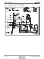
WIRING DIAGRAMS
8.3
Outdoor Unit: GC 24 1PH R410A
SM DELTA 1-E.0 GB
CONTENTS
8-3
WIRING DIAGRAMS
8.4
8-4
Outdoor Unit: OU7-24 1PH R410A
CONTENTS
SM DELTA 1-E.0 GB
WIRING DIAGRAMS
8.5
Outdoor Unit: OU7-24 3PH R410A
SM DELTA 1-E.0 GB
CONTENTS
8-5
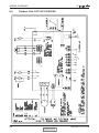
WIRING DIAGRAMS
8.6
8-6
Outdoor Unit: OU7-24Z R410A
CONTENTS
SM DELTA 1-E.0 GB
ELECTRICAL CONNECTIONS
9.
ELECTRICAL CONNECTIONS
9.1
DELTA 18 / 21 1PH
INDOOR UNIT
POWER SUPPLY
1PH 220-240V 50Hz
OUTDOOR UNIT
CIRCULIT BREAKER
(NOT SUPPLIED)
CONNECTED ONLY
HEAT - PUMP UNIT
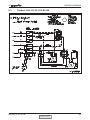
9.2
DELTA 24 1PH (power supply to Outdoor unit)
INDOOR UNIT
POWER SUPPLY
1PH 220-240V 50Hz
OUTDOOR UNIT
CIRCULIT BREAKER
(NOT SUPPLIED)
CONNECTED ONLY
HEAT - PUMP UNIT
SM DELTA 1-E.0 GB
CONTENTS
9-1
REFRIGERATION DIAGRAMS
10.
REFRIGERATION DIAGRAMS
10.1
Heat Pump Models
10.1.1
DELTA 18 R410A
OUTDOOR UNIT
INDOOR UNIT
Service
port
Compressor
Sensor
Reverse
valve
Capillary
tube
Strainer
Outdoor coil
Sensor
Valves
Flared
connection
Capillary
tube
Indoor coil
Check
valve
COOLING MODE
OUTDOOR UNIT
INDOOR UNIT
Service
port
Compressor
Sensor
Reverse
valve
Sensor
Valves
Flared
connection
Capillary
tube
Capillary
tube
Outdoor coil
Strainer
Indoor coil
Check
valve
HEATING MODE
SM DELTA 1-E.0 GB
CONTENTS
10-1
REFRIGERATION DIAGRAMS
10.1.2
10-2
DELTA 24 / OU7-24 R410A
CONTENTS
Service Manual - ALPHA
REFRIGERATION DIAGRAMS
10.1.3
DELTA 24 / OU7-24Z R410A
SM DELTA 1-E.0 GB
CONTENTS
10-3
REFRIGERATION DIAGRAMS
10.2
Cooling Only Models
10.2.1
DELTA 18, 21, 24 R410A
OUTDOOR UNIT
INDOOR UNIT
Compressor
Service
port
Sensor
Valves
Capillary
tube
Outdoor coil
10-4
Flared
connection
Indoor coil
Strainer
CONTENTS
Service Manual - ALPHA
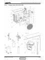
TUBING CONNECTIONS
11.
TUBING CONNECTIONS
TUBE (Inch)
¼”
”
½”
”
¾”
11-13
13-20
11-13
40-45
13-20
11-13
60-65
18-25
11-13
70-75
18-25
11-13
80-85
40-50
11-13
TORQUE (Nm)
Flare Nuts
Valve Cap
Service Port Cap
1.
2.
3.
4.
5.
6.
7.
8.
Valve Protection Cap-end
Refrigerant Valve Port (use Allen wrench to open/close)
Valve Protection Cap
Refrigerant Valve
Service Port Cap
Flare Nut
Unit Back Side
Copper Tube
When the outdoor unit is installed above the indoor unit an oil trap is required every 5m along
the suction line at the lowest point of the riser. Incase the indoor unit is installed above the
outdoor, no trap is required.
SM DELTA 1-E.0 GB
CONTENTS
11-1
CONTROL SYSTEM
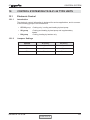
12.
CONTROL SYSTEM DELTA18-21-24 TYPE UNITS
12.1
Electronic Control
12.1.1
Introduction
The electronic control information is designed for service applications, and is common
to the following groups of air-conditioners:
• ST/ RC group -Cooling only / cooling and heating by heat pump.
• SH group
-Cooling and heating by heat pump and supplementary
heater.
• RH group
-Cooling, heating by heaters only.
12.1.2
Jumpers Settings
GROUP
J6 Setting
J2 Setting
ST / RC
Open
Open
SH
Closed
Open
RH
Closed
Closed
SM DELTA 1-E.0 GB
CONTENTS
12-1
CONTROL SYSTEM
12.2
Legend
AC
- Alternate Current
A/C
ANY
CLOCK
COMP
CPU
ELUM
E²PROM, EEP
HE
HPC
H/W
ICP
ICT
IF, IFAN
IR
LEVEL1
LEVEL2/3
LEVEL4
Max
Min
min
NA
OCP
OCT
OF, OFAN
OPER
Para.
RAT
RC
R/C
RCT
RH
RT
RV
SB, STBY
sec
Sect
SH
SPT
ST
S/W
TEMP
W/O
- Air-Conditioner
- ON or OFF status
- ON/OFF Operation Input, (dry contact)
- Compressor
- Central Processing Unit
- Extended Louver Upward Movement (Software Jumper)
- Erase Enable Programmable Read Only Memory
- Heating Element
- High Pressure Control
- Hardware
- Indoor Condensation Pump
- Indoor Coil Temperature (RT2) sensor
- Indoor Fan
- Infra Red
- Normal Water Level
- Medium/High Water Level
- Overflow Level
- Maximum
- Minimum
- Minute (time)
- Not Applicable
- Outdoor Condensation Pump
- Outdoor Coil Temperature (RT3) sensor
- Outdoor Fan
- Operate
- Paragraph
- Return Air Temperature (RT1) sensor
- Reverse Cycle (Heat Pump)
- Remote Control
- Remote Control Temperature
- Resistance Heater
- Room Temperature (i.e. RCT in IFEEL mode, RAT otherwise)
- Reversing Valve
- Stand-By
- Second (time)
- Section
- Supplementary Heater
- Set Point Temperature
- Standard (a Model with Cooling Only)
- Software
- Temperature
- Without
WVL
ΔT
- Water Valve
- The difference between SPT and RT.
in Heat Mode:ΔT = SPT-RT
in Cool/Dry/Fan Mode: ΔT = RT-SPT
12-2
CONTENTS
SM DELTA 1-E.0 GB
CONTROL SYSTEM
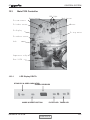
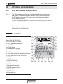
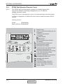
12.3
Main PCB Controller
/('OLJKW
5HVHWEXWWRQ
0RGHEXWWRQ
7RURRPVHQVRU
7RLQGRRUVHQVRU
%X]]HU
7RGLVSOD\
7RVWHSPRWRU
7RRXWGRRUVHQVRU
/RFN
&RPSUHVVRUUHOD\
)XVH$
12.3.1
LED Display DELTA
STAND BY & OPER. INDICATOR
SIGNAL RECEIVER
MODE & RESET BUTTON
SM DELTA 1-E.0 GB
FILTER LED TIMER LED
CONTENTS
12-3
CONTROL SYSTEM
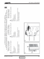
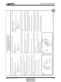
12.4
General functions
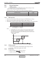
12.4.1
COMP operation
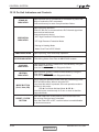
For each Mode including POWER OFF & SB, a Min time delay of 3 min
before COMP restarting, excluding DEICING Mode
The Min operation time of COMP under different operating conditions is
Operation Mode
Heat, Cool or Auto Modes
Fan, Dry, Overflow, Protection modes, or mode change
12.4.2
Min operation time of
COMP
3 min.
ignored
IFAN operation
•
Min time interval between IFAN speed change in AUTOFAN Mode, is 30 sec.
•
Min time interval between IFAN speed change in H/M/L Mode is 1 sec.
•
IFAN speed in Heat/Cool Autofan Mode is determined according to the following table:
ΔT
ΔT ≥ 2
2 ≥ ΔT ≥ 1
1 ≥ ΔT
where
IFAN Speed
HIGH
MED
LOW
in Heat Mode:ΔT = SPT-RT
in Cool Mode:ΔT = RT-SPT
Note:
•
•
In Heat Mode, the rules in section 4.0.3 have the higher priority.
The table above can be represent by a hysteresis curve which
will minimize the switching of the IFAN relay and will minimize the
change in IFAN speed:
IFAN speed
H
M
L
1
12.4.3
12.4.4
12-4
2
3
T [oc]
OFAN operation
•
Min time interval between OFAN ON/OFF state change is 30 sec.
•
In general, OFAN starts together with COMP.
HE operation
•
Minimum Heaters ON or OFF time is 30 sec.
•
Heaters can be activated only if IFAN is on.
CONTENTS
SM DELTA 1-E.0 GB
CONTROL SYSTEM
12.4.5
Protections
12.4.6
•
High pressure protection is applicable to all operating modes.
•
Deicing control is valid in Heat and Auto Heat Mode only.
•
Defrosting control is valid in Dry, Cool, Heat and Auto Modes.
•
No reset after protection modes.
Thermistors operation
12.4.6.1
•
Return air Temp. is detected by RAT (RT1) in normal Mode, or by RCT (R/C sensor)
in I-FEEL Mode.
•
Indoor Coil Temp. is detected by ICT (RT2).
Definition of thermistor faults:
a.
Thermistor is disconnected The thermistor reading is below -30oc.
b.
Thermistor is shorted The thermistor reading is over 75oc.
c.
Thermistor Temp reading doesn’t change (irrelevant for RT1) (i) This test is performed only once after a unit is switched from
OFF/STBY to operation. At the first occurrence of 10 min
continuous COMP operation, the current ICT & OCT are
compared with those when the COMP was switched from OFF
to ON 10 min before. If the ΔT is less than 3oc, the thermistor is
regarded as defective.
(ii) The ICT and OCT no-change error can be disabled together by
connecting a4.7 kohm resistor (5%) to the OCT connector. These
resistors are equivalent to a thermistor at 43+/-1oc and 48+/-1oc
respectively.
(iii) Connecting a 4.7k resistor to the ICT connector will disable the
ICT no-change error only.
SM DELTA 1-E.0 GB
CONTENTS
12-5
CONTROL SYSTEM
12.4.6.2
Cases for disabling thermistor short/disconnected detection
i.
The detection of thermistor faults (a) and (b) above, are disabled when Deicer
Protection is started. The detection will be enabled again only after (1) the
deicing is completed, and (2) COMP has been restarted and operated for 30
sec.
ii. When all the following conditions are fulfilled:
a.
4.7K Ohm resistor is connected on the OCT
b.
IFAN is OFF
c.
Compressor is ON
d.
ICT < -30 (disconnected)
This condition come to detect and prevent IFAN operation in Deicer in multi spilt
units.
12.4.6.3
i.
Handling the thermistor faults in a COMP unit
ICT/OCT thermistor is disconnected or shorted The invalid thermistor temperature is replaced by 43oc, so that the unit
can continue the normal operation. All protections related to that faulty
thermistor will be disabled. For example, in case of any ICT fault, the ICT
high pressure protection in Heat Mode and ICT defrost protection in Cool
Mode will not operate anymore. The same is also applied to the OCT fault.
ii.
RAT thermistor is disconnected or shorted –
The RAT will be derived from the ICT by using the equations :
Heat Mode: RAT=ICT/2.3
Cool Mode
RAT=ICT*4
Notes:
• In case of any thermistor failure, the STBY LED will be blinking until the
fault condition is corrected.
• User can use the system diagnostics function to find out the nature of
the thermistor faults.
i.
RAT thermistor is disconnected or shorted –
System will operate continuously in the last IFAN & WVL status when
turned ON.
Notes:
• As in the COMP unit, the STBY LED will be blinking to indicate a
thermistor fault. And, the user can use the system diagnostics function
to find out the nature of the fault.
12-6
CONTENTS
SM DELTA 1-E.0 GB
CONTROL SYSTEM
12.5
1)
2)
Cooling Mode - General
Room Temperature, RT, is detected by
• RAT in normal operation, or
• RCT (R/C sensor) in I-FEEL mode.
The resolution of RT is 1oc.
• RT is activating COMP/WVL if (RT > SPT), and
• RT is stopping COMP/WVL if (RT =< SPT).
3)
Indoor Coil Temp is detected by ICT (RT2).
4)
Outdoor Coil Temp is detected by OCT (RT3).
5)
A WVL-RC/SH will work in Cooling Mode when
• ICT < 16oc in general (see Sect 2.2.2 for details), and
• Unit is not operating in Fan Mode.
6)
OFAN OPERATIONS
• OFAN starts together with COMP in general.
SM DELTA 1-E.0 GB
CONTENTS
12-7
CONTROL SYSTEM
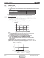
12.5.1
Cooling
Mode:
Temp:
Fan:
Timer:
I Feel:
Cool, Auto (at Cooling)
Selected desired temperature.
HIGH, MED, LOW
Any
On or Off
Control function
Maintains room temp at desired level by comparing RT and SPT.
(RT - SPT) [ oc]
+3
+2
+1
0
-1
-2
ON
COMP
(WVL) OFF
ON
OFAN
OFF
USER FAN SPEED
IFAN
ON
RV
OFF
Note:
1) IFAN is always running at High, Medium or Low speed selected by user.
2) In IFEEL mode, the Room Temperature (RT) is the RCT from a R/C. Otherwise, the
RT is the RAT from the Room Thermistor.
12-8
CONTENTS
SM DELTA 1-E.0 GB
CONTROL SYSTEM
12.5.2
Cooling with Autofan
Mode:
Temp:
Fan:
Timer:
I Feel:
Cool, Auto (at cooling)
Selected desired temperature
Auto
Any
On or Off
Control function
Maintains room temp at desired level and controls the IFAN speed for optimal comfort.
(RT - SPT) [ oc]
+3
+2
+1
0
-1
-2
ON
COMP
(WVL)
OFF
ON
OFAN
OFF
H
IFAN
M
L
ON
RV
OFF
SM DELTA 1-E.0 GB
CONTENTS
12-9
CONTROL SYSTEM
12.6
Heating Mode
12.6.1
Heating Mode - General
•
In heating Mode, temp. compensation schedule will be activated for wall mounted
units.
Add to SPT
SPT [oc]
I-FEEL ON
0 oc
0 oc
18 ≤ SPT ≤ 27
27 < SPT ≤ 30
I-FEEL OFF
+2 oc
+3 oc
Notes :
• No compensation will be activated in Forced operation modes
12.6.2
IF operating rules
•
•
As a general rule for RC and SH groups, when COMP is ON, excluding
protection modes, IFAN will be switched ON if
ICT > 35oc or
at the IFTC 30 sec after the COMP is switched ON. In
this case, the IFAN will be started at low speed.
IFAN Speed
EMD/ELD
Any
Low
EMD/ELD
Stop
General :
For WAX :
30
15
35
20
40
25
ICT [oc]
Notes :
1) In SH or RC group, if HE is set to OFF due to low ICT, IFAN will be
switched to LOW and will be turned OFF after 30 sec.
2) An exception to this rule (4.0.3.a) is the Back-up mode for SH.
• In RC and SH groups, whenever COMP & HE are both
OFF, excluding protection modes, IFAN operation will be according
to the following:
In other models IFAN will operate in low speed for 30 sec and then stop. If
COMP is OFF for more than 3 minutes and IFEEL Mode is inactive, IFAN will
operate in low speed according to the following graph:
IFAN (Low Speed)
ON
OFF
SPT+4
12-10
SPT+6
CONTENTS
ICT [oc]
SM DELTA 1-E.0 GB
CONTROL SYSTEM
12.6.3
HE operation
•
For all Groups, HE can be ON only when IFAN is ON.
•
For all Groups, HE switches to OFF when ICT > 50 oc, and is activated
again when ICT ≤ 45oc.
•
In SH or RC group, HE operation is limited by the following graph:
HE
ON
OFF
General :
For WAX :
30
15
35
20
40
45
50
ICT [oc]
• Back-up mode for SH group
After COMP has been working for 5 minutes, HE & IFAN are activated even
if the ICT is still below 35oc. This situation is called Back-up Mode. Both
HE & IFAN will work in Back-up Mode until the ICT reaches 35oc. Then, the
operation goes on in the usual mode .
SM DELTA 1-E.0 GB
CONTENTS
12-11
CONTROL SYSTEM
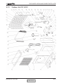
12.6.4
Heating, RC or SH Group
Mode:
Temp:
Fan:
Timer:
I Feel:
Heat, Auto (at heating)
Selected desired temperature
HIGH, MED, LOW
Any
On or Off
Control function
Maintains room temp. at desired level by comparing RAT or RCT to SPT.
(RT - SPT) [ oc]
+2
+1
0
-1
-2
-3
ON
COMP
(WVL)
OFF
ON
HE1
OFF
ON
HE2
OFF
H/M/L
IFAN
L
OFF
Note 1
Note 2
ON
RV
12-12
OFF
CONTENTS
SM DELTA 1-E.0 GB
CONTROL SYSTEM
12.6.5
Heating, RC or SH Group with Autofan
Mode:
Temp:
Fan:
Timer:
I Feel:
Heat, Auto (at heating)
Selected desired temperature
Auto
Any
On or Off
Control function
Maintains room temp at desired level by controlling COMP, IFAN and OFAN.
(RT - SPT) [ oc]
+2
+1
0
-1
-2
-3
ON
COMP
(WVL)
OFF
ON
HE1
OFF
ON
HE2
OFF
H
M
IFAN
L
OFF
Note 1
Note 2
ON
RV
OFF
SM DELTA 1-E.0 GB
CONTENTS
12-13
CONTROL SYSTEM
12.6.6
OFAN operation is controlled by the graph below when
1. (RAT ≥ SPT – 2oc), AND
2. (ICT ≥ 45oc), AND
3. (COMP is ON)
Otherwise, OFAN runs together with COMP.
OCT [oc]
+3
+2
+1
0
-1
ON
OFAN
12-14
OFF
CONTENTS
SM DELTA 1-E.0 GB
CONTROL SYSTEM
12.7
Automatic Cooling or Heating
12.7.1
Automatic Cooling or Heating - General
• Switching-temperature between Cooling and Heating is SPT ± 3oc.
• Autofan in Automatic Cooling and Heating Mode will activate “Cooling
with Autofan Mode” and “Heating with Autofan Mode” respectively.
• When the Auto Mode is started with SPT +/-0oc, the unit will not select
Auto Heat or Auto Cool mode immediately. Instead, the unit will be in
a temporary Fan Mode with IFAN operating at low speed.
The proper Auto Heat mode or Auto Cool will be started whenever the RT
reaches SPT-1oc or SPT+1oc respectively.
• For RC & SH units, Mode change between Auto Heat & Auto Cool
Modes is possible only after the COMP has been OFF during the
last T minutes.
Mode Change
Auto Cool to Auto Heat
Auto Heat to Auto Cool
•
time, T
3 min
4 min
When unit is changed form Cool/Dry mode to Auto Mode, the unit
will continue to operate at (Auto) Cool Mode until the conditions for
switching from Auto Cool to Auto Heat are satisfied.
Similarly, when unit is changed from Heat Mode to Auto Mode, the
unit will continue to operate at (Auto) Heat Mode until the conditions
for switching from Auto Heat to Auto Cool are satisfied.
SM DELTA 1-E.0 GB
CONTENTS
12-15
CONTROL SYSTEM
12.7.2
Auto Cooling or Heating, RC or SH Groups
Mode:
Temp:
Fan:
Timer:
I Feel:
Auto
Selected desired temperature
Any
Any
On or Off
Control function
Maintains room temp at desired level by selecting between cooling and heating modes.
(RT - SPT) [ oc]
+3
+2
+1
0
-1
-2
-3
Auto Heat Mode
ON
COMP
& OFAN
Auto Cool Mode
Auto Heat Mode
> 4 min
> 3 min
(3)
(3)
OFF
ON
HE1
OFF
(5)
ON
HE2
OFF
H/M/L/OFF
IFAN
H/M/L/OFF
L/OFF
USER FAN SPEED
L/OFF
L/OFF
> 3 min
ON
RV
12-16
H/M/L/OFF
> 2 min
(4)
(4)
OFF
CONTENTS
SM DELTA 1-E.0 GB
CONTROL SYSTEM
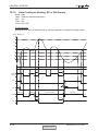
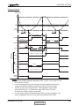
12.8 Dry Mode
12.8.1
Dry, ST or RC group
Mode: Dry
Temp: Selected desired temp
Fan: Low (automatically selected by software)
Timer: Any
I FEEL:
Any
Control function
Reduce room humidity with minimum temp. fluctuations by operating in Cool Mode with
low speed IFAN.
(RT - SPT) [ oc]
+2
+1
0
10
20
40
30
50
Time [min]
-1
-2
DRY-ON
DRY
DRY-OFF
LOW
IFAN
OFF
5 minutes COMP
ON time
ON
COMP
& OFAN
OFF
Max 15 minutes
ON
HE1
& HE2
3.5
min
Note1
Max 15 minutes
6 min
Note 2
OFF
ON
RV
OFF
Notes :
• When Dry is ON, the COMP is forced OFF for 3.5 min (longer than the
3 min Min COMP-Off time) after every 15 min of continuous COMP
operation.
• When Dry is OFF, the COMP is forced ON for 6 min (longer than the 3
min Min COMP-On time) after every 15 min of continuous COMP OFF
time.
• When Dry is changed from ON to OFF or vice versa, the limits
mentioned in (1) & (2) are ignored. The COMP operation is only
controlled by the 3 min Min OFF time and 1 min Min ON time.
• In Dry Mode, IFAN is LOW when COMP is ON, and is OFF when
COMP is OFF.
SM DELTA 1-E.0 GB
CONTENTS
12-17
CONTROL SYSTEM
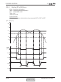
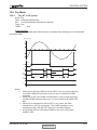
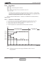
12.9
Protection
12.9.1
Cooling Mode Protections
Indoor Coil Defrost
Mode:
Temp:
Fan:
Timer:
I Feel:
Cooling, Dry, Auto
Selected desired temp.
Any
Any
On or Off
Control Function
Protect the indoor coil from ice formation at low ambient temperature.
ICT [oc]
+14
+5
+2
+1
0
-1
-6
t1
t2
t3
t1
t1
ON
OFAN
OFF
ON
COMP
OFF
ON
IFAN
OFF
J7 OPEN
J7 CLOSED
t1 = 5 min minimum for each COMP starting
t2 = OFAN cycling (alternate between ON and OFF every 30 sec) for 20 min
maximum
t3 = COMP and OFAN stop for 10 min minimum
Notes:
•
•
12-18
When J7 is closed (connected), OFAN cycling is cancelled and the
set temperature for COMP & OFAN cut-out and cut-in are changed.
COMP & OFAN are forced OFF when ICT =< -6oc, and are kept OFF
until ICT > 14oc.
For WAX model, the defrost processes is simpler. When J7 is open,
COMP & OFAN are forced OFF when ICT =< -1oc, and are kept OFF
until ICT > 5oc. When J7 is closed, the WAX defrosting process is the
same as that of the other models (R.H.S. of the graph above). In both
cases, the ICT checking in t2 and t3 are not applied.
CONTENTS
SM DELTA 1-E.0 GB
CONTROL SYSTEM
12.3.2
High Pressure Protection
Mode:
Temp:
Fan:
Timer:
I Feel:
(Auto) Cooling or Dry
Selected desired temp.
Any
Any
On or Off
Control Function
To protect the COMP from the high pressure built-up in the outdoor coil during normal
cooling operation, by switching OFF the IFAN and COMP.
OCT [oc]
For all models except WAX & P2000
For WAX & P2000 models
68
66
61
55
52
Any
COMP OFF
COMP is forced OFF
COMP is forced OFF
OFAN is forced ON
OFAN is forced ON
Any
OFAN
ON
OFAN follow operation of
COMP
Any
IFAN
L
IFAN forced
to LOW
ON
OPER
LED
Blink
Note:
• The ICT is also monitored during Cool and Dry mode, in case the RV control circuit
is faulty. Whenever ICT reaches 70oc, which indicates a high pressure in the indoor
coil, the COMP will be forced off automatically. The COMP can be turned on again only
after the ICT is under 70oc again and after the 3 min COMP ON delay time. The OPER
LED will not blink in this case.
SM DELTA 1-E.0 GB
CONTENTS
12-19
CONTROL SYSTEM
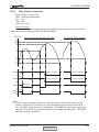
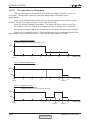
12.9.3
Heating Mode Protections
Outdoor coil Deicing (excluding RH Group)
Mode: Heating, Auto (at heating)
Temp: Selected desired Temp
Fan: Any
Timer: Any
I FEEL:
Any
Control function
Protects the Outdoor coil from ice formation by controlling COMP & RV operation.
Scope
This new deicer is designed to operate at extreme temp conditions. The deicing cycle
could be triggered from:
1. OCT temp and time between two consecutive deicing cycles.
2. Detection of ice forming by change of the OCT temp.
Both algorithms adjust the time between deicing cycles to optimize the A/C
performance. The algorithm will automatically increase the time between deicing cycles
and reduce the deicing cycle as needed.
The algorithm uses EEPROM data to operate.
12-20
CONTENTS
SM DELTA 1-E.0 GB
CONTROL SYSTEM
Deicing procedure
OCT [oc]
12
0
DOC
DST
(DDT)
3 min
3 min
36s
max 12 min.
36s
ON
COMP
OFF
DI (note 1)
DI (note 2)
ON
OFAN
OFF
30s
30s
ON
RV
DT
OFF
RC or WAX units
all SH units
except WAX
ANY
IFAN
L
IFAN is forced to Low Speed
ON
HE
ANY
HEs are forced ON
ANY
IFAN
OFF
Note 3
ANY
HE
OFF
HEs are forced OFF
ON
OPER
LED
BLINK
Notes :
• At the first COMP activation after SB or OFF, if (OCT < 0oc), then DI = 10
min, else DI = 40 min.
• In the following Deicing cycles, the time interval between two Deicing
cycles activation is between 30 to 80 min (refer to the flow chart).
• For RC group, HEs are forced OFF. IFAN operation is as in Heat
Mode, Sect 4.0.3.a, i.e. IFAN will be set to OFF when ICT<30oc.
For WAX, the IFAN is simply forced OFF.
• For SH group, HEs are forced ON and IFAN is forced to operate in Low
speed, regardless of the ICT and difference between RAT & SPT.
SM DELTA 1-E.0 GB
CONTENTS
12-21
CONTROL SYSTEM
12.9.4
High pressure protection (excluding RH Group)
Mode:
Fan:
Timer:
I Feel:
(Auto) Heating
Any
Any
On or Off
Control Function
Protect the Compressor from high pressure by switching OFF the OFAN and COMP.
ICT [oc]
For all models except WAX
For WAX model
67
66
61
55
52
Any
COMP Off
COMP is forced OFF
COMP is forced OFF
Any
OFAN
Off
OFAN is force
Off
ON
OPER
LED
BLINK
Notes:
12-22
•
IFAN, HE1 and HE2 will be activated according to the relevant
Heating Mode Sect.
•
In case of any malfunction in the relay control circuit, the OCT is also
monitored during heating mode. Whenever OCT reaches 70oc, which indicates
a high pressure in the outdoor coil, the COMP will be forced off automatically.
The COMP can be turned on again only after the 3 min COMP ON delay and the
OCT is under 70oc. The OPER LED will not blink in this case.
CONTENTS
SM DELTA 1-E.0 GB
CONTROL SYSTEM
12.10
Timer
Mode:
Temp.
Fan:
Timer:
I Feel:
Any
Selected desired temp
Any
Timer On, Timer Off
On or Off
Control function
•
Starts or stops the unit operation after pre-set time. If RC-1 is used,
the timer setting will be (0.5 - 24 Hr) from the moment the timer is set.
The minimum resolution is 30 minutes.
If RC-2 or later version of remote controls is used, the timer
setting will be (0:00 - 23:50) real time with 10 minutes resolution.
•
After power failure, all pre-set timers are cleared. The system is
forced to STBY mode and the Timer LED indicator is blinked to
indicate the situation. The LED keeps blinking until the timer settings
can be reloaded from a R/C message.
Note: If all timers are inactive, the system will not be forced
OFF after the power failure. The last OPER/STBY status will
be loaded from the EEP instead.
•
When the A/C receives any valid message from a R/C, the current
ON/OFF timer settings will be replaced by the new timer settings in
the R/C message.
Note: The following timer related operations will not affect the
A/C operating mode (Heat/Cool/Auto/Dry/Fan) setting.
• Set ON/OFF timer
• Clear ON/OFF timer
• R/C ON Timer is time-up
• R/C OFF Timer is time-up
E.g.
When a STBY A/C unit (with Cool Mode setting in its EEP) is
turned on by the ON-TIMER of a R/C with heat mode setting,
the A/C will start in Cool Mode.
SM DELTA 1-E.0 GB
CONTENTS
12-23
CONTROL SYSTEM
12.11
Forced Operation
Forced operation allows units to start, stop and operate in Cooling or Heating in pre-set
temperature according to the following table:
Pre-set Temp for :
Forced operation
mode
WMF, WMN, WNG models
Cooling
22°C
Heating
28°C
Note:
•
•
•
12-24
While under the forced operation, the temperature compensation
schedule.
The forced operation is activated when the mode button on the
Display Board is used to switch the unit to Cool or Heat mode.
The IFAN is always set to Autofan Speed in forced operation.
CONTENTS
SM DELTA 1-E.0 GB
CONTROL SYSTEM
12.12
Sleep Mode
Mode:
Temp:
Fan:
Timer:
I Feel:
Any
Set – desired temperature selected
Any
Interact with Sleep Timer as described in sect 12.2
On or Off
The Sleep mode is activated by using the sleep button on the R/C. In Sleep Mode,
the unit will automatically adjust the SPT to turn up/down the room temperature (RT)
gradually to provide maximum comfort to the user in sleep.
Sleep is treated as TIMER function. Therefore, the TIMER LED is activated similar to
TIMER function.
12.12.1
Adjustment in Sleep Mode
1. in cool, auto cool or dry modes, the SPT adjustment is positive (from 0 to +3oc).
2. In heat or auto heat modes, the SPT adjustment is negative (from 0 to -3oc).
3. In other modes, there is no SPT adjustment.
4. The SPT adjustment is cancelled when the Sleep mode is cancelled.
RT
7 Hours Sleep operation
for Normal Sleep Mode
Unit is turned to SB
after Sleep
SPT+3
Cool, Dry modes
SPT+2
SPT+1
SPT
SPT-1
SPT-2
Heat mode
SPT-3
Start
Sleep
1
2
3
4
5
6
7
8
Time [Hr]
Note: If Off-timer is active, the unit may go to SB before or after 7 hours of
sleep operation.
SM DELTA 1-E.0 GB
CONTENTS
12-25
CONTROL SYSTEM
12.12.2
Time adjustment in Sleep Mode
The user can make use of the Off-Timer to extend the Sleep Time from 7 hours to 12
hour (max). The operation of the new “Extended Sleep Mode” is illustrated by the
graphs below.
Case 1 is the Standard Sleep Mode, which is the only sleep mode in previous version
of MCU. The A/C unit simply works for 7 hours, then goes to SB.
Case 2 is the new Extended Sleep Mode. If an active Off-Timer is set to turn off the
A/C between 7-12 hour, relative to the starting of Sleep, the Sleep time is extended.
And, instead of going to SB at the 7th hour, the A/C will work until reaching the Off-time.
Case 3 is an exception to case 2. The Sleep Mode will not be extended to the Off-Time
when the Off-Timer is preceded by an On-Timer, which is also between 7-12 hour.
Case 1 : Standard Sleep Mode
Condition : Off-timer is not set or is beyond 12 hour.
Oper
SB
Start
Sleep
2
4
6
7
8
10
6
7
8
10
12
Time [Hr]
12
Time [Hr]
12
Time [Hr]
Case 2 : Extended Sleep Mode
Condition : Off-timer is set at 7-12 hour.
Oper
SB
Start
Sleep
2
4
Off-timer
Case 3 : Exception to Case 2
Condition : Off-timer is set at 7-12 hour
On-timer is set at 7-12 hour and before Off-timer
Oper
SB
Start
Sleep
12-26
2
4
6
7
8
10
On-timer
CONTENTS
Off-timer
SM DELTA 1-E.0 GB
CONTROL SYSTEM
12.13
Clogged Air Filter
Filter LED ON after 512 HR.
Filter LED is turned OFF, and the Filter Timer is restarted by pressing the reset button.
SM DELTA 1-E.0 GB
CONTENTS
12-27
CONTROL SYSTEM
12.14 Controller Self-Test Procedure
12.14.1
By Shorting Test Jumper J1
SELF-TEST FLOW CHART
FOR CONTROLLER (VERSION 4V5 OR HIGHER)
Step 1
SHORT JUMPER
J1
(CONTROL PCB)
RC/ST TEST
MODEL
CONFIGURATION
TEST
Step 2
PRESS ON
POWER
BUTTON
STEP MOTOR TEST
FREQUENCY
TEST
Step 3
PRESS ON
MODE BUTTON
STANDBY
LEDS OFF
OPERATE
LEDS ON TEST
TIMER
AUTO RELAY
TEST
COOL
HEAT
INDOOR FAN
SPEED TEST
COMPRESSOR
OUTDOOR FAN
Step 4
PRESS ON RESET
BUTTON
BUZZER TEST
(ONE BEEP SOUND)
Step 5
PRESS ON FAN
BUTTON ON THE
REMOTE CONTROL
REMOTE CONTROL
TO CPU COMUNICATION
(TWO BEEPS SOUNDS)
R.V.
LOW
MEDIUM
Step 6
PRESS ON MODE
BUTTON
THERMISTOR ANALOG
VOLTAGE CHECKING
Step 7
PRESS ON MODE
BUTTON
EEPROM MEMORY
TEST
Step 8
DISCONNECT
JUMPER
J1
END OF SELF
TEST
12-28
CONTENTS
HIGH
SM DELTA 1-E.0 GB
CONTROL SYSTEM
12.14.2
By Remote Control Settings:
a.
1: TURNING ON THE POWER.
Turn ON the power, make sure that the unit is in operation.
b.
STEP 2 : ENABLE SELF-TEST MODE
c.
•
Use the remote control to send the first settings to display / indoor unit
HEAT mode, HIGH IFAN, set temperature to 16 ºC, no I-FEEL Sleep or
any other timer settings are needed.
•
Cover the IR transmitter components in the remote control so that it will
not transmit the signals to the indoor unit display.
•
Use the remote control to send the second settings to display / indoor unit
COOL mode, LOW IFAN, no I-FEEL Sleep or any other timer settings.
•
Uncover the remote control IR transmitter and change the temperature
settings. If the display/indoor unit receive the settings properly the
following steps will start:
STEP 3: MODEL SETTING CONFIRMATION
•
The STAND-BY and COOL LEDS will indicate the operation mode as
follows:
OPERATION MODE
STAND-BY LED
COOL LED
ST
ON
OFF
RC
OFF
OFF
SH
OFF
ON
RH
ON
ON
•
MODEL
WNG
WMN1
WMN4
WMN2/WHX
WMN3
Testing the Model configuration. Selected by the COMP, STAND-BY,
TIMER LEDS and FILTER will indicate the model configuration as follows
(the relevant line for this manual is highlighted):
COMP
ON
ON
OFF
OFF
OFF
OPERATE LED
OFF
ON
OFF
ON
ON
TIMER LED
OFF
OFF
ON
OFF
ON
FILTER LED
OFF
ON
OFF
ON
ON
In this term the step motor will turn to HOME POSITION.
SM DELTA 1-E.0 GB
CONTENTS
12-29
CONTROL SYSTEM
d.
STEP 4 : AUTO LED WALK TEST.
•
All the LEDS will turn OFF.
•
All the LEDS will turn ON for 1 second one by one in the following
sequence:
STAND-BY OPERATE TIMER FILTER COOL •
e.
HEAT.
In PRX all the LEDS will turn ON for 1 second one by one in the following
sequence : 18 °c 20 °c 22 °c 24 °c 26 °c 28 °c 30 °c High IFAN Auto IFAN Med IFAN Low IFAN STAND-BY
TIMER FILTER COOL HEAT.
STEP 5: AUTO REALY WALK TEST:
•
All relays will energize one by one in the following sequence:
COMPRESSOR OUTDOOR FANR. V. HEATER 1 HEATER 2
INDOOR WATER PUMP SWING or OUTDOOR WATER PUMP INDOOR FAN: LOW MID HIGH.
•
f.
STEP 6: FREQUENCY TESTING:
•
g.
When the relay walk test is completed, the next test will start
automatically.
If the frequency measuring process fails the COOL LED will turn ON.
In order to move to the next step, press ON/OFF button on the remote
control.
STEP 7: INPUT TEST.
•
The test purpose is to check the analog real time indicators (thermistors,
LEVEL and clock) according to the table below.
LED Indicator
STBY LED
OPER LED
TIMER LED
FILTER LED
COOL LED
HEAT LED
h.
Condition for LED to be ON
Room thermistor ≠ 25°c
Indoor coil thermistor ≠ 25°c
Outdoor coil thermistor ≠ 25°c
Clock
LEVEL 2&3
LEVEL 4
STEP 8: TIMING RESET TEST (WATCH DOG).
•
The test purpose is to verify that the CPU rise time after power failure
is between 1 to 3 sec, test results are indicated on the LEDS : STANDBY,OPER, TIMER and FILTER turning ON one by one.
•
The results of the test are coded as follows:
Pass condition:
1 sec - STAND-BY and OPER are turned ON
2 sec - STAND-BY, OPER and TIMER are turned ON
12-30
CONTENTS
SM DELTA 1-E.0 GB
CONTROL SYSTEM
Fail condition:
0 sec - STAND-BY is turned ON
3 sec - STAND-BY, OPER, TIMER and FILTER are turned ON
•
i.
When the timing reset test is completed, the next test will start
automatically.
STEP 9: MEMORY TEST (EEPROM)
•
The test purpose is to check if the memory is functioning correctly. The test
result is reported by using the STAND-BY and FILTER LEDS:
LED Indicator
Condition for LED to be ON
STAND-BY LED
Test passed
FILTER LED
Test failed
AT THIS POINT THE SELF-TEST IS COMPLETED.
In order to terminate Self-Test mode the User can change the unit setting from COOL
Mode, LOW FAN to COOL Mode, MED FAN or to wait without using the remote control
for 60 sec.
Values of Sensors Temperature VS. Voltage (DC)
Temp. (*C) Voltage (V) Temp. (*C) Voltage (V) Temp. (*C) Voltage (V) Temp. (*C) Voltage (V)
-20
4.554
2
3.744
24
2.555
46
1.487
-19
4.529
3
3.695
-18
4.502
4
3.646
25
2.5
47
1.447
26
2.445
48
1.409
-17
4.475
5
3.595
27
2.391
49
1.371
-16
4.446
6
3.544
28
2.338
50
1.334
-15
4.417
7
3.492
29
2.284
51
1.298
-14
4.386
-13
4.354
8
3.439
30
2.232
52
1.263
9
3.386
31
2.18
53
1.228
-12
4.322
10
3.332
32
2.128
54
1.195
-11
4.287
11
3.278
33
2.077
55
1.162
-10
4.252
12
3.223
34
2.027
56
1.13
9
4.216
13
3.168
35
1.978
57
1.099
-8
4.178
14
3.113
36
1.929
58
1.069
-7
4.14
15
3.058
37
1.881
59
1.04
-6
4.1
16
3.002
38
1.834
60
1.011
-5
4.059
17
2.946
39
1.798
61
0.983
-4
4.017
18
2.89
40
1.742
62
0.956
-3
3.974
19
2.833
41
1.698
63
0.929
-2
3.93
20
2.777
42
1.654
64
0.904
-1
3.885
21
2.722
43
1.611
65
0.879
0
3.839
22
2.666
44
1.569
66
0.854
1
3.792
23
2.61
45
1.527
67
0.831
SM DELTA 1-E.0 GB
CONTENTS
12-31
CONTROL SYSTEM
12.15 On Unit Indicators and Controls
STAND BY
INDICATOR
OPERATION
INDICATOR
Lights up when the Air Conditioner is connected to power and
ready to receive the R/C commands
Blinks continuously in case of any thermistor failure.
Lights up during operation.
Blinks for 300 ms, to announce that a R/C infrared signal has
been received and stored.
Blinks continuously during
• OCT High Pressure Protection Mode
• ICT High Pressure Protection Mode
• Deicing in Heating Mode
• Water Over Flow in ECC Model
12-32
TIMER INDICATOR
Lights up during Timer and Sleep operation.
FILTER INDICATOR
Lights up when Air Filter needs to be cleaned.
Blinks during Water Over Flow in MBX/P2000 models.
COOLING
INDICATOR
Lights up when system is switched to Cool Mode by using the
Mode Switch on the unit.
Show the thermistor status in Diagnostic Mode
HEATING
INDICATOR
Lights up when system is switched Heat Mode by using the
Mode Switch on the unit.
Show the thermistor status in Diagnostic Mode.
MODE BUTTON
(Cool, Heat, SB)
Use to cycle the operation mode of the A/C unit among COOL,
HEAT and SB modes, without using the R/C.
Every time this switch is pressed, the next operation mode is
selected, in this order :
SB Cool Mode Heat Mode SB ...
Press this button continuously for 5 sec or more to start the
Diagnostic Mode.
RESET / FILTER
BUTTON
When the Filter LED is ON, press to turn off the Filter LED
after a clean filter has been reinstalled.
When the Filter LED is OFF, use this button to enable/disable
the buzzer announcer.
CONTENTS
SM DELTA 1-E.0 GB
CONTROL SYSTEM
12.16
Clock Random Delay From 0 to 2.5 seconds
0=
1=
Clock Switch Open
Clock Switch close
The Clock is activate according to the following table:
A/C STATE
CLOCK STATE
CLOCK ACTION
(before clock is changed) (before clock is changed) (clock is changed)
A/C NEW STATE
(after clock is changed)
ON
1
0
OFF
OFF
0
1
ON
OFF by
interrupt (1)
1
0
OFF
ON by
interrupt (1)
0
1
ON
Notes :
1.
Clock can be interrupted by :
• R/C - POWER ON/OFF Push-button.
• R/C - TIMER.
• R/C - SLEEP.
• A/C - MODE SWITCH.
2. Any change in the CLOCK level during the first 6 sec after the system
Reset is ignored.
SM DELTA 1-E.0 GB
CONTENTS
12-33
CONTROL SYSTEM
12.2
System Diagnostics
Pressing Mode button for 5-10 seconds in SB or any other operation mode will activate
diagnostic mode by the acknowledgment of 3 short beeps and lighting of COOL and
HEAT LEDs.
In diagnostic mode, system problems will be indicated by blinking of Heat & Cool LEDs.
The coding method will be as follow:
Heat led will blink 5 times in 5 seconds, and then will be shut off for the next 5 seconds.
Cool led will blink during the same 5 seconds according to the following table:
No
Problem
○
○
○
○
○
1
RT1 is disconnected
○
●
●
●
●
2
RT1 is shorted
○
●
●
●
○
3
(Reserved)
○
●
●
○
●
4
RT2 is disconnected
●
○
●
●
●
5
RT2 is shorted
●
○
●
●
○
6
(Reserved)
●
○
●
○
●
7
8
RT2 temp reading doesn’t change
RT3 is disconnected
●
●
○
●
●
○
○
●
○
●
9
RT3 is shorted
●
●
○
●
○
10
(Reserved)
●
●
○
○
●
11
RT3 temp reading doesn’t change
●
●
○
○
○
12
RT2 & RT3 temp reading doesn’t change
●
○
○
○
○
○ - ON,
● - OFF
Notes:
1. If faults occur in more than one thermistor (except case number 12 on
table above), only one fault will be indicated according to the following
RT3, RT2, RT1.
the
order:
2. A/C will jump out to normal mode if sending a command by the R/C in
system diagnostics mode. If this command from the R/C contain a Group
ID will become the new Group ID of the ELCON unit.
the
ID, this
12-34
CONTENTS
SM DELTA 1-E.0 GB
TROUBLESHOOTING
13.
1.
TROUBLESHOOTING
SYMPTON
PROBABLE CAUSE
The stand-by
There is no correct voltage between
indicator (red led) on the line and neutral terminals on
the central control
main P.C.B
display panel doesn’t
light up.
CORRECTIVE ACTION
-If the voltage is low repair power
supply.
-If there is no voltage repair general
wiring.
-If there is correct voltage replace main
or display P.C.B’S
2.
The operation
The remote control batteries are
indicator (green led) discharged
on the central control
display panel does
not light up.
-Replace batteries of the remote
control.
3.
The operation
indicator (green led)
does not light up
when starting from
unit.
-Replace P.C.B if necessary.
4.
The indoor fan does Check the voltage between indoor
not function correctly. fan terminals on the main P.C.B
5.
The outdoor fan does Check the voltage between out door -If there is no voltage replace main
not function correctly. fan terminals on the main P.C.B
P.C.B
Check main P.C.B and display
P.C.B
There is voltage between outdoor
fan terminals on the outdoor unit.
There is no voltage between
outdoor fan terminals on the
outdoor unit.
6.
The compressor does Check voltage on compressor
not start up.
terminals on the outdoor unit. (with
ammeter)
Check if there is correct voltage
between compressor terminals on
the outdoor unit.
-If there is voltage replace capacitor or
motor.
-Replace capacitor or motor.
-Check and repair electrical wiring
between indoor and outdoor units
-If no voltage replace main P.C.B
-If low voltage repair power supply.
-If the voltage correct replace capacitor
or compressor.
-If there is no voltage repair electrical
wiring between indoor and outdoor
units.
7.
The refrigeration
system does not
function correctly.
8
No cooling or heating Outdoor fan motor faulty or other
only indoor fan
fault caused, compressor overload
works.
protection cut out.
SM DELTA 1-E.0 GB
Check for leaks or restrictions.
With ammeter. Pressure gauge or
surface thermometer.
CONTENTS
-Repair refrigeration system and charge
refrigerant if necessary.
-Replace P.C.B.
-Outdoor fan blocked remove
obstructions.
13-1
TROUBLESHOOTING
SYMPTON
PROBABLE CAUSE
CORRECTIVE ACTION
9.
Only indoor fan and
compressor working.
Outdoor fan blocked.
10.
Only indoor fan
working.
-Run capacitor of outdoor fan motor -Replace capacitor.
faulty.
-Windings of outdoor fan are
-Replace motor.
shorted.
11.
No cooling or heating -Overload safety device on
compressor is cut out (low voltage
takes place, indoor
or high temperature).
fans working.
-Remove obstructions.
-Check for proper voltage, switch off
power and try again after one hour.
-Replace compressor capacitor.
-Compressor runs capacitor faulty.
-Replace compressor.
-Compressor windings are shorted.
12.
No air supply
-Indoor fan motor is blocked or
at indoor unit,
turns slowly.
compressor operates. -Indoor fan run capacitor faulty.
-Motor windings are shorted.
-Check voltage, repair wiring if
necessary.
-Check fan wheel if it is tight enough on
motor shaft, tighten if necessary.
13.
Partial, limited air
supply at indoor unit.
Lack of refrigerant (will
accompanied by whistling noise)
cause ice formation on indoor unit
coil in cooling mode.
-charge the unit after localizing leak.
14.
Water accumulates
and over flow from
indoor unit section.
Drain tube or spout of drain pan
clogged.
-Disassemble plastic drain tube from
spout of indoor unit drain pan.
15.
Water dripping from
Water drain outlet is clogged.
outdoor unit base, (in
heating mode).
-Open outdoor unit cover clean out
water outlet clean the base inside
thoroughly.
16.
Freeze-up of outdoor -Faulty outdoor thermistor.
coil in heating mode,
poor heating effect
-Faulty control cable.
in room, indoor fan
operates.
-Outdoor temperature is below
design conditions.
-Replace thermistor.
-Repair control cable.
-Shut unit off, it cannot work properly.
-Remove obstructions.
-Outdoor unit air outlet is blocked.
17.
13-2
Unit is in heat mode
but operating in
cooling.
-Faulty RV coil.
-Replace RV coil.
-RV coil is ok valve is stuck position. -Replace the reversing valve.
CONTENTS
SM DELTA 1-E.0 GB
EXPLODED VIEWS AND SPARE PARTS LISTS
14.
EXPLODED VIEWS AND SPARE PARTS LISTS
14.1
Indoor Unit: DELTA 18, 21, 24
SM DELTA 1-E.0 GB
CONTENTS
14-1
EXPLODED VIEWS AND SPARE PARTS LISTS
14.2
.
1
2
3
4
5
6
7
8
9
9
10
10
11
12
13
14
15
16
17
18
20
20
21
22
22
23
24
25
26
28
29
30
31
34
36
14-2
Indoor Unit: DELTA 18, 21, 24
Item
Description
Quan.
465020098
452919800
4518113
465720204
452919600
462350084
453046600
452917300
465210009
452917500
452917600
452930700
452918200
4518662
453024900
453053800
452920100
452919400
453134300R
453116500R
452918800
453050300
4519147
452919200
467300197R
452919100
4516263
467300201R
438082
467400025
452919500
4520416
438600R
4518651
453057900
452918700
4518657
Front Plate/Delta 18&24 Fagor
Filter
Fiber Filter Assy.
Silk-Screen Front Frame Assy./Delta 18-24 Fagor Electra
Screw cover
Evaporator Assy./WNG21/24 R410A
Evaporator Assy./WNG18 R410A
Air outlet
Drain Pipe for Israel /WNG18/24/30
Horizontal flap A
Horizontal flap B
Vertical flap A
Vertical flap B
Bearing assy fan
Impeller fan
Base assy./WNG18
Mount bracket/WNG-18
Joint/Unit housing
Resin Motor 26W/WNG24 LED (DELTA21,24)
Resin Motor 18W/WNG18 LED (DELTA18)
Cover/motor
STEP MOTOR B
Power Cord Clip
Tie/connection Wire
Display Board/Delta 18 F
Support/sensor
SENSOR BASE
Controller/Delta F 18 S/W:10V14
Thermistor Indoor coil BLACK.
Indoor Air Inlet Temperature Sensor
Cover/terminal
Defrost cable EXPORT UNITS.
Remote controller RC3-RC 973-600-00
Cover Side Motor
Gear BOX ASSY
Support/horizontal louver
TUBE LOCK
CONTENTS
1
2
1
1
3
1
1
1
1
1
1
12
2
1
1
1
1
1
1
1
1
1
1
1
1
1
1
1
1
1
1
1
1
1
1
2
1
SM DELTA 1-E.0 GB
EXPLODED VIEWS AND SPARE PARTS LISTS
14.3
Outdoor Unit: GC 18 ST
SM DELTA 1-E.0 GB
CONTENTS
14-3
EXPLODED VIEWS AND SPARE PARTS LISTS
14.4
Outdoor Unit: GC 18 ST
.
Part .
Description
1
2
3
4
5
6
7
8
9
10
11
12
13
14
15
16
17
18
19
20
21
22
23
24
25
26
27
28
29
30
31
32
33
34
35
36
37
38
39
40
41
42
4517144
452795700
452989200
4516786
4516985
455000506
455000104
204107
4521744
4522469
4521733
4521340
4525427
453089900
4519000
4517345
4526922
4516766
4526530
4526531
4526931
4526839
4523145
452821900
4523338
452977200
452976200
4526291
4525938
452977000
452976800
4517028
4516758
452976000
452821300
452988800
4526509
4526864
4526585
4526510
4523141
4516788
FAN COVER PP+UV
PAINTED LEFT CABINET ASSY
Base welding plate assy.
PAINTED RIGHT CABINET ASSY
Partition Plate
Compressor Capacitor With Screw 45uF (CBB65)
Double patch Capacitor for fan motor 4uF (CBB61S)
Cable clip Nylon
3 Poles Terminal Block (4mm2)
4 LEVEL TERMINAL BLOCK
3 Poles Terminal Block ( 6mm2)
Controller Box
Clip for capacitance(d=50)
Compressor Assy.PA200X2CS-4KU1
Spring of compressor heater
COMPRESSOR WIRE ASSY. 2.5mm2
heater for compressor
PAINTED VALVE PLATE ASSY
LOW PRESS VALVE (R410A)
High press valve(R410A)
filter welding assy. 2
filter welding assy.
R.lifter
Capillary assy. for cooling
Accumulator assy.
Low pressure pipe
Suction pipe 1
Muffler
PAINTED RIGHT-BACK CABINET ASSY
Condenser pipe assy.
Discharge pipe 2
PAINTED LEFT-BACK GRILL
SMALL HANDLE
Discharge pipe 1
Condenser-Distributing Soldering Assy.GC-18ST R410A
Insulation for compressor PA215/240
MOTOR BRAKECT (new)
motor YYK85E-6
connect for motor backet
FAN D=460mm (3 blade)
Hexagon locked nut M10
PAINTED TOP COVER ASSY
14-4
Quantity
CONTENTS
1
1
1
1
1
1
1
2
1
1
1
1
1
1
1
1
1
1
1
1
1
1
1
1
1
1
1
1
1
1
1
1
1
1
1
1
1
1
1
1
1
1
SM DELTA 1-E.0 GB
EXPLODED VIEWS AND SPARE PARTS LISTS
14.5
Outdoor Unit GC 18 RC
SM DELTA 1-E.0 GB
CONTENTS
14-5
EXPLODED VIEWS AND SPARE PARTS LISTS
14.6
Outdoor Unit: GC 18 RC
.
Part .
Description
1
2
3
4
5
6
7
8
9
10
11
12
13
14
15
16
17
18
19
20
21
22
23
24
25
26
27
28
29
30
31
32
33
34
35
36
37
38
39
40
41
42
43
44
45
46
47
4517144
452795700
452989200
4516786
4516985
455000506
455000104
204107
4524907
4521744
4522469
4521733
4521340
4525427
453089900
4519000
4517345
4526922
4516766
4526530
4526531
4526931
4526839
4523145
4526840
4523338
452976500
452976600
452976400
4526291
4525938
4526522
4526589
452976100
452987800
4517028
4516758
452976000
452796500
452988800
452976200
4526509
4526862
4526585
4526510
4523141
4516788
COVER PP+UV
PAINTED LEFT CABINET ASSY
Base welding plate assy.
PAINTED RIGHT CABINET ASSY
Partition Plate
Compressor Capacitor With Screw 45uF (CBB65)
Double patch Capacitor for fan motor 4uF (CBB61S)
Cable clip Nylon
contactor (CJX9B-25S/01)
3 Poles Terminal Block (4mm2)
4 LEVEL TERMINAL BLOCK
3 Poles Terminal Block ( 6mm2)
Controller Box
Clip for capacitance(d=50)
Compressor Assy.PA200X2CS-4KU1
Spring of compressor heater
COMPRESSOR WIRE ASSY. 2.5mm2
Heater for compressor
PAINTED VALVE PLATE ASSY
LOW PRESS VALVE (R410A)
High press valve(R410A)
filter welding assy. 2
filter welding assy.
R.lifter
Single-way welding assy.
Accumulator assy.
Suction pipe 2
Low pressure pipe
Condenser pipe assy.
Muffler
PAINTED RIGHT-BACK CABINET ASSY
FOUR-WAY VALVE R410A
4-Way Valve Coil FOR R410A
Discharge pipe 2
4-way welding assy. for GC18RC R410A PA200
PAINTED LEFT-BACK GRILL
SMALL HANDLE
Discharge pipe 1
Condenser-Distributing Soldering Assy.GC-18RC R410A
Insulation for compressor PA215/240
Suction pipe 1
MOTOR BRAKECT (new)
motor YYK85E-6B for GC18RC
connect for motor backet
FAN D=460mm (3 blade)
M10 Hexagon locked nut M10
PAINTED TOP COVER ASSY
14-6
Quantity
CONTENTS
1
1
1
1
1
1
1
2
1
1
1
1
1
1
1
1
1
1
1
1
1
1
1
1
1
1
1
1
1
1
1
1
1
1
1
1
1
1
1
1
1
1
1
1
1
1
1
SM DELTA 1-E.0 GB
EXPLODED VIEWS AND SPARE PARTS LISTS
14.7
Outdoor Unit: GC 21 RC
SM DELTA 1-E.0 GB
CONTENTS
14-7
EXPLODED VIEWS AND SPARE PARTS LISTS
14.8
Outdoor Unit: GC 21 RC
.
Part Description
1
2
3
4
5
6
7
8
9
10
11
12
13
14
15
16
17
18
19
20
21
22
23
24
25
26
27
28
29
30
31
32
33
34
35
36
37
38
39
40
41
42
43
44
45
46
47
4517144
452795700
452989200
4516786
4516985
455000507
455000104
204107
4524907
4521744
4522469
4521733
4521340
4525427
452975900
4519000
4517345
452988900
4516766
4526513
4526514
452891100
452891200
4523145
463750005
4523338
452976500
452976700
452976300
4526291
4525938
4526522
4526589
452976100
452987700
4517028
4516758
452976000
452882900
452988800
452976200
4526509
4526864
452907400
4526510
4523141
4516788
FAN COVER PP+UV
PAINTED LEFT CABINET ASSY
Base welding plate assy.
PAINTED RIGHT CABINET ASSY
Partition Plate
Compressor Capacitor With Screw 50uF (CBB65)
Double patch Capacitor for fan motor 4uF (CBB61S)
Cable clip Nylon
Contactor (CJX9B-25S/01)
3 Poles Terminal Block (4mm2)
4 LEVEL TERMINAL BLOCK
3 Poles Terminal Block ( 6mm2)
Controller Box
Clip for capacitance(d=50)
Compressor assy.PA240X2CS-4KU1
Spring fo compressor heater
COMPRESSOR WIRE ASSY. 2.5mm2
Heater for compressor
PAINTED VALVE PLATE ASSY
LOW PRESS VALVE (R410A)
Hight press valve(R410A)
Filter assy 1
Filter assy 2
R.lifter
Single-way welding assy
Accumulator assy
Suction pipe 2
Low pressure pipe
Condenser pipe assy
Muffler
PAINTED RIGHT-BACK CABINET ASSY
FOUR-WAY VALVE R410A
4-Way Valve Coil FOR R410A
Discharge pipe 2
4-way welding assy.
PAINTED LEFT-BACK GRILL
SMALL HANDLE
Discharge pipe 1
Condenser and distributor welding assy.
Insulation for compressor
Suction pipe 1 for PA240
MOTOR BRAKECT (new)
Motor YYK85E-6
Hook for condenser
FAN D=460mm (3 blade)
Hexagon locked nut M10
PAINTED TOP COVER ASSY
14-8
Qty
CONTENTS
1
1
1
1
1
1
1
2
1
1
1
1
1
1
1
1
1
1
1
1
1
1
1
1
1
1
1
1
1
1
1
1
1
1
1
1
1
1
1
1
1
1
1
1
1
1
1
SM DELTA 1-E.0 GB
EXPLODED VIEWS AND SPARE PARTS LISTS
14.9
Outdoor Unit: GC 21 ST
SM DELTA 1-E.0 GB
CONTENTS
14-9
EXPLODED VIEWS AND SPARE PARTS LISTS
14.10
Outdoor Unit: GC 21 ST
Part Description
Qty
1
2
4517144
452795700
COVER PP+UV
PAINTED LEFT CABINET ASSY
1
1
3
452989200
Base welding plate assy.
1
4
4516786
PAINTED RIGHT CABINET ASSY
1
5
4516985
Partition Plate
1
6
455000507
Compressor Capacitor With Screw 50uF (CBB65)
1
7
455000104
Double patch Capacitor for fan motor 4uF (CBB61S)
1
8
204107
Cable clip Nylon
2
9
4522469
4 LEVEL TERMINAL BLOCK
1
10
4521744
3 Poles Terminal Block (4mm2)
1
11
4521733
3 Poles Terminal Block ( 6mm2)
1
12
4521340
Controller Box
1
13
4525427
Clip for capacitance(d=50)
1
14
452975900
Compressor assy.PA240X2CS-4KU1
1
15
4519000
Spring fo compressor heater
1
16
4517345
COMPRESSOR WIRE ASSY. 2.5mm2
1
17
452988900
Heater for compressor
1
18
4516766
PAINTED VALVE PLATE ASSY
1
19
4526513
LOW PRESS VALVE (R410A)
1
20
4526514
Hight press valve(R410A)
1
21
452891100
Filter assy 1
1
22
452891200
Filter assy 2
1
23
4523145
R.lifter
1
24
463600001
Capillary welding assy.
1
25
4523338
Accumulator assy
1
26
452977300
Low pressure pipe
1
27
452976200
Suction pipe 1 for PA240
1
28
4526291
Muffler
1
29
4525938
PAINTED RIGHT-BACK CABINET ASSY
1
30
452977100
Condenser pipe assy.
1
31
453018400
Discharge pipe 2
1
32
4517028
PAINTED LEFT-BACK GRILL
1
33
4516758
SMALL HANDLE
1
34
452976000
Discharge pipe 1
1
35
452897800
Condenser and distributor welding assy.
1
36
452988800
Insulation for compressor
1
37
4526509
MOTOR BRAKECT (new)
1
38
4526864
motor YYK85E-6
1
39
452907400
Hook for condenser
1
40
4526510
FAN D=460mm (3 blade)
1
41
42
4523141
4516788
Hexagon locked nut M10
PAINTED TOP COVER ASSY
1
1
14-10
CONTENTS
SM DELTA 1-E.0 GB
EXPLODED VIEWS AND SPARE PARTS LISTS
14.11
Outdoor Unit GCN 12 RC
SM DELTA 1-E.0 GB
CONTENTS
14-11
EXPLODED VIEWS AND SPARE PARTS LISTS
14.12
Outdoor Unit: GC 24 ST
Part Description
1
2
3
4
5
6
7
8
9
10
11
12
13
14
15
16
17
18
19
20
21
22
23
24
25
26
27
28
29
30
31
32
33
34
35
36
37
38
39
40
41
4517144
452795700
452881901
4516786
4516985
455000301
455000104
204107
4522469
4521744
4521733
4521340
4525427
452864700
4519000
4517345
452892100
4516766
4526513
4526514
452891100
452891200
4523145
452901200
452891400
452893600
452883600
4526291
4525938
452893700
4517028
4516758
452893800
452882900
452891300
4526509
4526864
452907400
4526510
4523141
4516788
FAN COVER PP+UV
PAINTED LEFT CABINET ASSY
Base plate paint assy.
PAINTED RIGHT CABINET ASSY
Partition Plate
Compressor Capacitor 55uF (CBB65)
Double patch Capacitor for fan
Cable clip Nylon
4 LEVEL TERMINAL BLOCK
3 Poles Terminal Block (4mm2)
3 Poles Terminal Block ( 6mm2)
Controller Box
(d=50) clip for capacitance
Compressor NN27VBAMT assy. for
Spring fo compressor heater
COMPRESSOR WIRE ASSY. 2.5mm2
Heater for compressor
PAINTED VALVE PLATE ASSY
LOW PRESS VALVE (R410A)
Hight press valve(R410A)
Filter assy 1
Filter assy 2
R.lifter
Capillary welding assy.
Accumulation assy
Suction pipe
Suction pipe assy. 2
Muffler
PAINTED RIGHT-BACK CABINET ASSY
Discharge tube 1
PAINTED LEFT-BACK GRILL
SMALL HANDLE
Discharge pipe 2
Condenser and distributor
Insulation for compressor NN27
MOTOR BRAKECT (new)
motor YYK85E-6
Hook for condenser
FAN D=460mm (3 blade)
M10 Hexagon locked nut M10
PAINTED TOP COVER ASSY
14-12
Qty
CONTENTS
1
1
1
1
1
1
1
2
1
1
1
1
1
1
1
1
1
1
1
1
1
1
1
1
1
1
1
1
1
1
1
1
1
1
1
1
1
1
1
1
1
SM DELTA 1-E.0 GB
EXPLODED VIEWS AND SPARE PARTS LISTS
14.13
Outdoor Unit GC 24 RC
SM DELTA 1-E.0 GB
CONTENTS
14-13
EXPLODED VIEWS AND SPARE PARTS LISTS
14.14
Outdoor Unit: GC 24 RC
Part Description
1
2
3
4
5
6
7
8
9
10
11
12
13
14
15
16
17
18
18
19
20
21
22
23
24
25
26
27
28
29
30
31
32
33
34
35
36
37
38
39
40
41
42
43
44
45
46
47
48
49
4517144
452795700
452881901
4516786
4516985
455000301
455000104
204107
4524907
4521744
4522469
4521733
4521340
4525427
452864700
4519000
4517345
452862100
452892100
4516766
4526513
4526514
452891100
452891200
4523145
452891600
452891400
452883700
452883800
452883500
4526291
4525938
4526522
4526589
452890700
452882800
4517028
4516758
452890800
452882900
452891300
452883600
4526509
4526864
452907400
4526510
4523141
4516788
452925700
192106
FAN COVER PP+UV
PAINTED LEFT CABINET ASSY
Base plate paint assy.
PAINTED RIGHT CABINET ASSY
Partition Plate
Compressor Capacitor 55uF (CBB65)
Double patch Capacitor for fan
Cable clip Nylon
contactor (CJX9B-25S/01)
3 Poles Terminal Block (4mm2)
4 LEVEL TERMINAL BLOCK
3 Poles Terminal Block ( 6mm2)
Controller Box
(d=50) clip for capacitance
Compressor NN27VBAMT assy. for
Spring fo compressor heater
COMPRESSOR WIRE ASSY. 2.5mm2
Base Bom for KCR-50M(SHX33SC4-U
Heater for compressor
PAINTED VALVE PLATE ASSY
LOW PRESS VALVE (R410A)
Hight press valve(R410A)
Filter assy 1
Filter assy 2
R.lifter
Single-way welding assy
Accumulation assy
Suction pipe
Low pressure pipe assy.
Condenser pipeassy.
Muffler
PAINTED RIGHT-BACK CABINET ASSY
FOUR-WAY VALVE R410A
4-Way Valve Coil FOR R410A
Dischage pipe 1
4-way welding assy.
PAINTED LEFT-BACK GRILL
SMALL HANDLE
Discharge tube 2
Condenser and distributor
Insulation for compressor NN27
Suction pipe assy. 2
MOTOR BRAKECT (new)
motor YYK85E-6
Hook for condenser
FAN D=460mm (3 blade)
M10 Hexagon locked nut M10
PAINTED TOP COVER ASSY
Pressure switch 4.2MPa/3.7MPa
Relay JQX-13F/220-2Z5 OR VE-R02 2Ca2
14-14
Qty
CONTENTS
1
1
1
1
1
1
1
2
1
1
1
1
1
1
1
1
1
1
1
1
1
1
1
1
1
1
1
1
1
1
1
1
1
1
1
1
1
1
1
1
1
1
1
1
1
1
1
1
1
1
SM DELTA 1-E.0 GB
EXPLODED VIEWS AND SPARE PARTS LISTS
14.15
Outdoor Unit: OU7-24 RC 1PH
SM DELTA 1-E.0 GB
CONTENTS
14-15
EXPLODED VIEWS AND SPARE PARTS LISTS
14.16
Outdoor Unit: OU7-24 RC 1PH
No
Part No
Description
1
437045
UPPER COVER EL13 OU LARGE
1
2
433280
SIDE PANEL OU7-24 R410A
1
3
436357
SMALL ELECTRICAL COVER OU
1
4
439329
FRONT COVER/CO' OU7-35/90 E
1
5
437091
OU SQUARE FAN GUARD
1
6
433705
NEW BASE ASSY OU 2005 LOCAL
1
7
433285
COIL OU7-24 HDR
1
8
4529604
AXIAL FAN D493*143
1
9
434062
MOTOR 86W,2S,OU7-24
1
10
433281
SIDE GUARD OU7-24 R410
1
11
436358
OU LEADING HANDLE
1
12
439342
MOTOR SUPPORT OU7-24
1
13
190443
HEATER CRANKCASE MITSUBISHI
1
14
433293
COMPRESSOR NN27VBAMT
1
15
433934
CAPILLARY HEATING ASSY OU7-24
1
16
433291
TUBING ASSY OU7 R410A
1
17
402495
BOARD TPHN 5B
1
18
442007
CAPACITOR 6mF 400V P1/P2
1
19
434716
THERMISTOR+CAP WTH CONNECTO
1
20
442011
CAPACITOR 25mF 400V P1/P2
1
20
442016
CAPACITOR 55mF 400V P1/P2
1
21
437274
COMPRESOR WIRING OU7/8-1PH
1
22
402283
SUCTION ACCUMULATOR 3x5/8"
1
24
437229
ELECTRICAL BOX TPHN
1
33
442466
VALVE COIL L700 MOLEX-SANHU
1
44
433816
SUCTION ASSY OU7 R410A
1
14-16
Qty
CONTENTS
SM DELTA 1-E.0 GB
EXPLODED VIEWS AND SPARE PARTS LISTS
14.17
Outdoor Unit: OU7-24 ST 1PH
SM DELTA 1-E.0 GB
CONTENTS
14-17
EXPLODED VIEWS AND SPARE PARTS LISTS
14.18
Outdoor Unit: OU7-24 ST 1PH
Part Description
1
437045
UPPER COVER EL13 OU LARGE
1
2
433280
SIDE PANEL OU7-24 R410A
1
3
436357
SMALL ELECTRICAL COVER OU
1
4
439329
FRONT COVER/CO' OU7-35/90 EL13
1
5
437091
OU SQUARE FAN GUARD
1
6
433705
NEW BASE ASSY OU 2005 LOCAL R4
1
7
433846
COIL OU7-24 ST
1
8
4529604
AXIAL FAN D493*143
1
9
434062
MOTOR 86W,2S,OU7-24
1
10
433281
SIDE GUARD OU7-24 R410
1
11
436358
OU LEADING HANDLE
1
12
439342
MOTOR SUPPORT OU7
1
13
190443
HEATER CRANKCASE MITSUBISHI CO
1
14
433293
COMPRESSOR NN27VBAMT
1
15
433845
CAPILLARY ASSY OU7-24 ST R410A
1
16
433817
TUBING ASSY OU7 ST R410A
1
17
402495
BOARD TPHN 5B
1
18
442007
CAPACITOR 6mF 400V P1/P2
1
19
434716
THERMISTOR+CAP WTH CONNECTOR L
1
20
442016
CAPACITOR 55mF 400V P1/P2
1
21
437274
COMPRESOR WIRING OU7/8-1PH MIT
1
22
402283
SUCTION ACCUMULATOR 3x5/8" 3. "
1
24
437229
ELECTRICAL BOX TPHN
1
44
433816
SUCTION ASSY OU7 R410A
1
45
433847
GAS VAVE ASSY OU7 ST R410A
1
14-18
Qty
CONTENTS
SM DELTA 1-E.0 GB
EXPLODED VIEWS AND SPARE PARTS LISTS
14.19
Outdoor Unit: OU7-24Z RC/ST 1PH
RSWLRQDO
20
18
44
17
24
19a
SM DELTA 1-E.0 GB
CONTENTS
14-19
EXPLODED VIEWS AND SPARE PARTS LISTS
14.20
Outdoor Unit: OU7-24Z RC/ST 1PH
Part
Description
1
437045
LARGE UPPER COVER CUE
1
2
433280
SIDE PANEL OU7-24 R410A
1
3
436357
SMALL ELECTRICAL COVER CUE
1
4
439329
COVERAIR COLLECTOR
1
5
437091
OU SQUARE FAN GUARD
1
6
433722
BASE ASSY OU7-24C EXPORT R410A
1
7
433285
COIL OU7-24 HDR
1
8
4529604
AXIAL FAN D493x143
1
9
434211
Replace by SP000000266 MOTOR+BRACKET
1
10
433281
SIDE GUARD OU7-24 R410
1
11
436358
TRANSPORT HANDLE CUE
1
12
439342
MOTOR BASE OU7
1
14
438795
COMPRESSOR GP270PAA
1
15
433934
CAPILLARY HEATING ASSY OU7-24 R410A
1
16
433660
TUBING ASSY OU7-24C R410A
1
17
413496
BOARD TPHN 5F (RoHS)
1
18
442007
CAPACITOR 6uF 400V
1
19a
434716
THERMISTOR L1050 (for coil)
1
20
442038
CAPACITOR 50mF 400V P1/P2
1
21
438627
COMPRESSOR WIRING TPHN-5F
1
24
437229
ELECTRICAL BOX TPHN
1
33
442520
VALVE COIL L700 MOLEX-DUNAN
1
44
192207
CONTACTOR 230V, 40A
1
14-20
Qty
CONTENTS
SM DELTA 1-E.0 GB
EXPLODED VIEWS AND SPARE PARTS LISTS
14.21
Outdoor Unit: OU7-24 RC 3PH
SM DELTA 1-E.0 GB
CONTENTS
14-21
EXPLODED VIEWS AND SPARE PARTS LISTS
14.22
Outdoor Unit: OU7-24 RC 3PH
Part Description
1
437045
UPPER COVER EL13 OU LARGE
1
2
433280
SIDE PANEL OU7-24 R410A
1
3
436357
SMALL ELECTRICAL COVER OU
1
4
439329
FRONT COVER/CO' OU7-35/90 EL13
1
5
437091
OU SQUARE FAN GUARD
1
6
433294
NEW BASE ASSY OU 2005 EXPORT R
1
7
433285
COIL OU7-24 HDR
1
8
4529604
AXIAL FAN D493*143
1
9
434062
MOTOR 86W,2S,OU7-24
1
10
433281
SIDE GUARD OU7-24 R410
1
11
436358
OU LEADING HANDLE
1
12
439342
MOTOR SUPPORT OU7
1
13
190443
HEATER CRANKCASE MITSUBISHI CO
1
14
433753
COMPRESSOR NN27YDAMT
1
15
433934
CAPILLARY HEATING ASSY OU7-24
1
16
433291
TUBING ASSY OU7 R410A
1
17
402494
BOARD TPHN 3C
1
18
442007
CAPACITOR 6mF 400V P1/P2
1
19
434716
THERMISTOR+CAP WTH CONNECTOR L
1
21
437278
COMPRESSOR WIRING OU7/8-3PH MI
1
22
402283
SUCTION ACCUMULATOR 3x5/8" 3. "
1
24
437229
ELECTRICAL BOX TPHN
1
25
439795
3PH MOTOR PROTECTOR
1
33
442466
VALVE COIL L700 MOLEX-SANHUA
1
44
433816
SUCTION ASSY OU7 R410A
1
14-22
Qty
CONTENTS
SM DELTA 1-E.0 GB
EXPLODED VIEWS AND SPARE PARTS LISTS
14.23
Outdoor Unit: OU7-24 ST 3PH
SM DELTA 1-E.0 GB
CONTENTS
14-23
EXPLODED VIEWS AND SPARE PARTS LISTS
14.24
Outdoor Unit: OU7-24 ST 3PH
Part Description
1
437045
UPPER COVER EL13 OU LARGE
1
2
433280
SIDE PANEL OU7-24 R410A
1
3
436357
SMALL ELECTRICAL COVER OU
1
4
439329
FRONT COVER/CO' OU7-35/90 EL13
1
5
437091
OU SQUARE FAN GUARD
1
6
433705
NEW BASE ASSY OU 2005 LOCAL R4
1
7
433846
COIL OU7-24 ST
1
8
4529604
AXIAL FAN D493*143
1
9
434062
MOTOR 86W,2S,OU7-24
1
10
433281
SIDE GUARD OU7-24 R410
1
11
436358
OU LEADING HANDLE
1
12
439342
MOTOR SUPPORT OU7
1
13
190443
HEATER CRANKCASE MITSUBISHI CO
1
14
433753
COMPRESSOR NN27YDAMT
1
15
433845
CAPILLARY ASSY OU7-24 ST R410A
1
16
433817
TUBING ASSY OU7 ST R410A
1
17
402494
BOARD TPHN 3C
1
18
442007
CAPACITOR 6mF 400V P1/P2
1
19
434716
THERMISTOR+CAP WTH CONNECTOR L
1
21
437278
COMPRESSOR WIRING OU7/8-3PH MI
1
22
402283
SUCTION ACCUMULATOR 3x5/8" 3. "
1
24
437229
ELECTRICAL BOX TPHN
1
25
439795
3PH MOTOR PROTECTOR
1
44
433816
SUCTION ASSY OU7 R410A
1
45
433847
GAS VAVE ASSY OU7 ST R410A
1
14-24
Qty
CONTENTS
SM DELTA 1-E.0 GB
OPTIONAL ACCESSORIES
15.
OPTIONAL ACCESSORIES
15.1
RCW Wall Mounted Remote Control
15.1.1
The RCW wall mounted remote control can be fitted to a large range
and models, It can be used as IR (wirless mode) or wired controler.
the RCW can control up to15 indoor units using the same settings
(on its wired aplication),
The max wiring length between the controller to the last indoor unit is 300m. for
application on WNG LED indoor units an additional interface PCB is needed.
Ordering code no’:
RCW –
436195
WNG add’ PCB - SP000000290.
ENGLISH
REMOTE CONTROL
1. START / STOP button
2. Operation mode selection
button COOLING, HEATING,
AUTO COOL / HEAT, DRY, FAN.
3. LOCAL temperature sensing button
4. FAN SPEED and
AUTO FAN button
5. Room temperature UP button
6. Room temperature DOWN Button
7. NIGHT button
8. Airflow direction MANUAL positioning control button
9. Airflow direction AUTO-CONTROL button
10. TIMER button
11. TIMER UP button
12. TIMER DOWN button
13. LCD operation display
14. LOCAL sensor
15. Infrared signal transmitter
16. ROOM temperature button
17. TIMER SET button
18. TIMER CLEAR button
19. Transmission sign
SM DELTA 1-E.0 GB
15
o
C
1
14
15
ON
OFF
2
WK
19
AUTO
LOCAL
5
13
6
4
2
1
7
16
3
9
10
CONTENTS
8
18
17
12
11
15-1
OPTIONAL ACCESSORIES
15.2
RCW2 Wall Mounted Remote Cntrol
15.2.1
The RCW2 wall mounted remote controler is a wired controler that
can provide affective controling management up to 15 different
settings and temp’ zones.
The RCW2 can be connected up to a max’ of 32 units,allowing a max wiring length
of 1000m. for application on WNG LED indoor units an additional interface PCB is
needed.
Ordering code no’:
RCW2 –
SP000000081
WNG add’ PCB - SP000000290
1
2
3
1
4
2
3
4
15-2
CONTENTS
Display screen.
Keys for raising and lowering the set
temperature.
Ventilation mode selection :
Low speed.
Medium speed.
High speed.
AUTO : Automatic speed selection.
ON / Standby.
Accessing the time setting mode.
Advancing the time setting.
Retarding the time setting.
Clearing memory of programmed time
settings in programming mode.
Day of the week selection key or sending
“I feel” local temperature setting.
Programming mode key.
“Copy” key, enabling zone parameters to
be duplicated for other zones.
Operating mode selection.
Day /Night key.
Current zone setting: zone above.
Current zone setting: zone below.
Louver : step by step or horizontal.
Louver : vertical.
SM DELTA 1-E.0 GB
OPTIONAL ACCESSORIES
15.3
A.S.K (All Season Kit)
The A.S.K is a pressure regulator to be installed on site in case the working conditions are below
the standard operating range of the unit in cooling mode.
The ASK allows working in cooling at low temp’ up to -10 ºC for rooms with high internal gains.
For units up to 7.2 KW kit code no’ – 7ACFH0077
For units up to 12 KW kit code no’ – 7ACFH0078
Documentation as shown on kits :
SM DELTA 1-E.0 GB
CONTENTS
15-3
OPTIONAL ACCESSORIES
15-4
CONTENTS
SM DELTA 1-E.0 GB
OPTIONAL ACCESSORIES
SM DELTA 1-E.0 GB
CONTENTS
15-5
OPTIONAL ACCESSORIES
15-6
CONTENTS
SM DELTA 1-E.0 GB
OPTIONAL ACCESSORIES
SM DELTA 1-E.0 GB
CONTENTS
15-7
APPENDIX A
APPENDIX A
INSTALLATION AND OPERATION MANUAL
INSTALLATION AND OPERATION MANUAL DELTA 18, 21, 24
SM DELTA 1-E.0 GB
CONTENTS
16-1