1
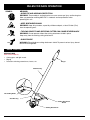
SS725r
Straight Shaft Trimmer Add-On
OPERATOR’S MANUAL
FOR QUESTIONS, CALL 1-800-345-8746 in U.S. or
1-800-265-6778 in CANADA
www.ryobi.com
IMPORTANT MANUAL
DO NOT THROW AWAY
INTRODUCTION
TABLE OF CONTENTS
THANK YOU
Thank you for buying this quality product. This modern
outdoor power tool will provide many hours of useful
service. You will find it to be a great labor-saving device.
This operator’s manual provides you with easy-to-understand operating instructions. Read the whole manual
and follow all the instructions to keep your new outdoor
power tool in top operating condition. The parts list at
the end of this manual contains all the information that
you need to order parts.
PRODUCT REFERENCES, ILLUSTRATIONS AND
SPECIFICATIONS
All information, illustrations and specifications
in this manual are based on the latest product
information available at the time of printing. We reserve
the right to make changes at any time without notice.
Copyright© 1999 Ryobi Outdoor Products, Inc.
All Rights Reserved.
Click-Link® is a registered trademark of Ryobi Outdoor
Products.
I.
Rules for Safe Operation . . . . . . . . . . . . . . . . . . . . . 3-5
A. Important Safety Instructions . . . . . . . . . . . . . . . 3-4
B. Safety and International Symbols . . . . . . . . . . . .4-5
C. Know Your Unit . . . . . . . . . . . . . . . . . . . . . . . . . . . . 5
II.
Operating Instructions . . . . . . . . . . . . . . . . . . . . . . 6-8
A. Operating the Click-Link System . . . . . . . . . . . . . . 6
B. Holding the Trimmer . . . . . . . . . . . . . . . . . . . . . . . 7
C. Adjusting Trimming Line Length . . . . . . . . . . . . . . 7
D. Tips for Best Trimming Results . . . . . . . . . . . . . . . 7
E. Decorative Trimming . . . . . . . . . . . . . . . . . . . . . . . 8
III. Maintenance and Repair Instructions . . . . . . . . . . 8-10
A. Line Installation for the SpeedSpool . . . . . . . . . . . 8
B. Installing a Prewound Reel . . . . . . . . . . . . . . . . . . 9
C. Cleaning the SpeedSpool . . . . . . . . . . . . . . . . . . 10
D. SpeedSpool Replacement Parts . . . . . . . . . . . . . 10
E. Cleaning . . . . . . . . . . . . . . . . . . . . . . . . . . . . . . . . 10
F. Storage . . . . . . . . . . . . . . . . . . . . . . . . . . . . . . . . . 10
IV. Troubleshooting Chart . . . . . . . . . . . . . . . . . . . . . . . 11
V. Specifications . . . . . . . . . . . . . . . . . . . . . . . . . . . . . . 11
VI. Parts List . . . . . . . . . . . . . . . . . . . . . . . . . . . . . . . . . . 12
SERVICE INFORMATION
VII. Warranty . . . . . . . . . . . . . . . . . . . . . . . . . . . . . . . . . . 14
Service on this unit both within and after the warranty
period should be performed only by an authorized and
approved service dealer.
Dial:
• 1-800-345-8746 or www.ryobi.com on the world wide
web for authorized service dealers in the United States
Or
• 1-800-265-6778 in Canada to obtain the listing of the
authorized service dealer nearest you.
CONTENTS OF CARTON
•
•
•
•
SS725r Straight Shaft Trimmer Add-On
Hanger
Operator's Manual with Parts List
Product Registration Card
to obtain the listing of the authorized service dealer
nearest you.
DO NOT RETURN THE UNIT TO THE RETAILER.
NOTE: PROOF OF PURCHASE WILL BE REQUIRED
FOR WARRANTY SERVICE.
Make sure this manual is carefully read and understood
before starting or operating this equipment.
THIS PRODUCT IS COVERED BY ONE OR MORE
US PATENTS, OTHER PATENTS PENDING.
WARNING!
Read the Operator’s Manual(s) and follow all warnings and safety instructions. Failure to do so can
result in serious injury to the operator and/or bystanders.
FOR QUESTIONS, CALL 1-800-345-8746 IN U.S. OR 1-800-265-6778 in CANADA
WARNING: The operation of any power tool can cause foreign objects to be thrown into your
eyes. This can lead to severe eye damage. Before commencing power tool operation, always
wear safety glasses or goggles that are marked as meeting ANSI Z87.1 standards, and a full
face shield when needed.
2
RULES FOR SAFE OPERATION
The purpose of safety symbols is to attract your
attention to possible dangers. The safety symbols,
and their explanations, deserve your careful attention
and understanding. The safety warnings do not by
themselves eliminate any danger. The instructions or
warnings they give are not substitutes for proper
accident prevention measures.
SYMBOL
MEANING
SAFETY ALERT SYMBOL: Indicates
danger, warning, or caution. Attention is
required in order to avoid serious personal
injury. May be used in conjunction with
other symbols or pictographs.
NOTE: Advises you of information or instructions vital to
the operation or maintenance of the equipment.
DANGER: Failure to obey a safety warning
will result in serious injury to yourself or to
others. Always follow the safety precautions
to reduce the risk of fire, electric shock, and
personal injury.
WARNING: Failure to obey a safety warning
can result in injury to yourself and others.
Always follow the safety precautions to
reduce the risk of fire, electric shock, and
personal injury.
CAUTION: Failure to obey a safety warning
may result in property damage or personal
injury to yourself or to others. Always follow
the safety precautions to reduce the risk of
fire, electric shock, and personal injury.
• IMPORTANT SAFETY INSTRUCTIONS •
READ ALL INSTRUCTIONS
BEFORE OPERATING
• Read the instructions carefully. Be familiar with the
controls and proper use of the unit. Carefully read this
manual and the operator’s manual of the unit that will
power this add-on.
• Do not operate this unit when tired, ill, or under the
influence of alcohol, drugs, or medication.
• Children and teens under the age of 15 must not use
the unit, except for teens guided by an adult.
• Use only 0.080 inch (2.03 mm) diameter genuine Ryobi
replacement line. Never use metal-reinforced line,
wire, or rope, etc.. These can break off and become a
dangerous projectile.
• This unit was not designed to be used as a
brushcutter. Do not attach or operate this unit with any
type of brushcutting blade or brushcutting attachment.
SAFETY WARNINGS FOR GAS TRIMMERS
WARNING: Gasoline is highly flammable, and its vapors
can explode if ignited. Take the following precautions:
• Store fuel only in containers specifically designed and
approved for the storage of such materials.
• Always stop the engine and allow it to cool before
filling the fuel tank. Never remove the cap of the fuel
tank, or add fuel, when the engine is hot. Never
operate the unit without the fuel cap securely in place.
Loosen the fuel tank cap slowly to relieve any pressure
in the tank.
• Mix and add fuel in a clean, well-ventilated area
outdoors where there are no sparks or flames. Slowly
remove the fuel cap only after stopping engine. Do not
smoke while fueling or mixing fuel. Wipe up any spilled
fuel from the unit immediately.
• Avoid creating a source of ignition for spilled fuel. Do
not start the engine until fuel vapors dissipate.
• Move the unit at least 30 feet (9.1 m) from the fueling
source and site before starting the engine. Do not
smoke, keep sparks and open flames from the area
while adding fuel or operating the unit.
• Never start or run the unit inside a closed room or
building. Breathing exhaust fumes can kill. Operate
this unit only in a well ventilated area outdoors.
SAFETY WARNINGS FOR ELECTRIC TRIMMERS
• WARNING: To reduce the risk of electrical shock, use
only extension cords approved for outdoor use, such
as an extension cord of cord type SW-A, SOW-A,
STW-A, STOW-A, SJW-A, SJOW-A, SJTW-W or
SJTOW-A. Extension cords are available from your
local retailer. Use only round-jacketed extension cords
approved for outdoor use.
• CORD SETS: Make sure your cord set is in good
condition. When using a cord set, be sure to use a
cord that is heavy enough to carry the current that
your unit will draw.An undersized cord set will cause a
drop in line voltage resulting in loss of power and
overheating. See the operator’s manual for the unit
that will power this add-on for the recommended cord
size.
• Inspect all extension cords and the unit power
connection periodically. Look closely for deterioration,
cuts or cracks in the insulation. Also inspect the
connections for damage. Replace the cords if any
defects or damage appear.
• Avoid dangerous environments. Never operate your
unit in damp or wet conditions. Moisture is a shock
hazard.
• Do not use the unit in the rain.
• Do not handle the plug or unit with wet hands or
standing on any wet surfaces.
• Do not leave the unit plugged in when not in use,
changing attachments or add-ons, or while
being serviced.
3
RULES FOR SAFE OPERATION
• Turn off all controls before unplugging.
• Keep hair, loose clothing, fingers, and all parts of body
away from openings and moving parts.
• Do not allow to be used as a toy. Close attention is
necessary when used by or near children.
WHILE OPERATING
• Wear safety glasses or goggles that are marked as
meeting ANSI Z87.1 standards, and ear/hearing protection when operating this unit. Wear a face or dust
mask if the operation is dusty.
• Wear heavy, long pants, boots, gloves and a long
sleeve shirt. Do not wear loose clothing, jewelry, short
pants, sandals or go barefoot. Secure hair above
shoulder level.
• The cutting attachment shield must always be in place
while operating the unit. Do not operate unit without
both trimming lines extended, and the proper line
installed. Do not extend the trimming line beyond the
length of the shield.
• Use the right tool. Use this unit only as described in
this manual. Do not use for any job except that for
which is intended.
• Be sure the cutting attachment is not in contact with
anything before starting the unit.
• Do not overreach. Always keep proper footing and
balance.
• Always hold the unit with both hands when operating.
Keep a firm grip on both the front and rear handle or
grips.
• Always stop the unit when work is delayed or when
walking from one cutting location to another.
• If you strike or become entangled with a foreign
object, stop the engine immediately and check for
damage. Do not operate before repairing damage. Do
not operate the unit with loose or damaged parts.
• Stop the unit IMMEDIATELY if you feel excessive
vibration. Vibration is a sign of trouble. Inspect
thoroughly for loose nuts, bolts or damage before
continuing. Repair or replace affected parts as
necessary.
• Stop and switch the unit to off for maintenance,
repair, or for changing add-ons attachments.
• Keep unit clean of vegetation and other materials.
They may become lodged between the cutting
attachment and shield.
• Use only genuine Ryobi replacement parts when
servicing this unit. These parts are available from
your authorized service dealer. Do not use parts,
accessories or attachments not authorized by Ryobi
for this unit. Doing so could lead to serious injury to
the user, or damage to the unit, and void your
warranty.
OTHER SAFETY WARNINGS
• Allow the unit to cool before storing or transporting.
Be sure to secure the unit while transporting.
• Store the unit inside in a dry place, either locked up or
up high to prevent unauthorized use or damage. Keep
out of the reach of children.
• Keep hands, face, and feet at a distance from all
moving parts. Do not touch or try to stop the cutting
attachment when it is rotating.
• Never douse or squirt the unit with water or any other
liquid. Keep handles dry, clean and free from debris.
Clean after each use, see Cleaning and Storage
instructions.
• Do not operate the engine faster than the speed
needed to cut, trim or edge. Do not run the engine at
high speed when not cutting.
• Keep these instructions. Refer to them often and use
them to instruct other users. If you loan someone this
unit, also loan them these instructions.
SAVE THESE INSTRUCTIONS
SAFETY AND INTERNATIONAL SYMBOLS
This operator's manual describes safety and international symbols and pictographs that may appear on this product.
Read the operator's manual for complete safety, assembly, operating and maintenance and repair information.
SYMBOL
MEANING
• SAFETY ALERT SYMBOL
Indicates danger, warning, or caution. May be used in conjunction with other
symbols or pictographs.
•WARNING - READ OPERATOR'S MANUAL
Read the Operator’s Manual(s) and follow all warnings and safety instructions.
Failure to do so can result in serious injury to the operator and/or bystanders.
• FOR SERVICE INFORMATION, CALL:
USA: 1-800-345-8746
CANADA: 1-800-265-6778
4
RULES FOR SAFE OPERATION
SYMBOL
MEANING
• WEAR EYE AND HEARING PROTECTION
WARNING: Thrown objects and loud noise can cause severe eye injury and hearing loss.
Wear eye protection meeting ANSI Z87.1 standards and ear protection when
operating this unit.
• KEEP BYSTANDERS AWAY
WARNING: Keep all bystanders, especially children and pets, at least 50 feet (15 m)
from the operating area.
• THROWN OBJECTS AND ROTATING CUTTER CAN CAUSE SEVERE INJURY
WARNING: Do not operate without the cutting attachment shield in place.
Keep away from the rotating cutting attachment.
• SHARP BLADE
WARNING: Sharp blade on cutting attachment shield. To prevent serious injury, do not
touch line cutting blade.
KNOW YOUR UNIT
APPLICATIONS
With Trimmer Add-On;
• Cutting grass and light weeds.
• Edging
• Decorative trimming around trees, fences, etc.
Hanger
Shaft Housing
Line Cutting Blade
Gear Housing
Cutting Attachment
Shield
Cutting Attachment
5
OPERATING INSTRUCTIONS
OPERATING THE CLICK-LINK® SYSTEM
The Click-Link® system enables the use of these
optional add-ons.
Blower/Vacuum . . . . . . . . . . . . . . . . . . . . . . . . . . BV720r
Cultivator . . . . . . . . . . . . . . . . . . . . . . . . . . . . . . GC720r
Hedge Trimmer (Gas units only) . . . . . . . . . . . . . HS720r
Snow Thrower (Gas units only) . . . . . . . . . . . . . . ST720r
Tree Pruner . . . . . . . . . . . . . . . . . . . . . . . . . . . . . TP720r
Sweeper/Blower . . . . . . . . . . . . . . . . . . . . . . . . . SB720r
Lawn Edger . . . . . . . . . . . . . . . . . . . . . . . . . . . . . LE720r
Turbo Blower . . . . . . . . . . . . . . . . . . . . . . . . . . . . TB720r
WARNING: Read and understand operator’s
manual for unit to be used with this add-on
prior to operation.
Removing the Add-Ons:
1. Turn the knob counterclockwise to loosen (Fig. 1).
2. Press and hold the release button (Fig. 2).
3. While firmly holding the upper shaft housing, pull the
cutting attachment or add-on straight out of the
Click-Link® coupler.
Release Button
Click-Link® Coupler
Primary Hole
Upper Shaft
Housing
Lower Shaft
Housing
Fig. 2
3. Turn the knob clockwise to tighten (Fig. 3).
CAUTION: Lock the release button in the
primary hole and securely tighten the knob
before operating this unit.
Installing the Add-Ons:
WARNING: To avoid serious personal injury,
shut unit off before removing or installing
add-ons.
NOTE: To make installing or removing the add-on easier,
place the unit on the ground or on a work bench.
Knob
1. Turn the knob counterclockwise to loosen (Fig. 1).
Click-Link® Coupler
Release Button
Fig. 3
CAUTION: The add-ons with the
Click-Link® system are to be used in the
primary hole unless stated otherwise in the
specific add-ons operator’s manual. Using
the wrong hole could lead to personal injury,
or damage to the unit.
Guide
Recess
Knob
Fig. 1
2. While firmly holding the add-on, push it straight into
the Click-Link® coupler (Fig. 2).
NOTE: Aligning the release button with the guide recess
will help the installation (Fig. 2).
6
Check Flex Shaft Engagement Prior to Using
1. Start the unit.
2. Briefly engage and release the trigger.
3. Check that add-on is operating.
4. If the add-on is not operating, remove add-on and
repeat steps for installing the add-on.
5. Recheck operation of add-on attachment.
OPERATING INSTRUCTIONS
HOLDING THE TRIMMER
WARNING: Always wear eye, hearing, foot
and body protection to reduce the risk of
injury when operating this unit.
Before operating the unit, stand in the operating position
(Figs. 4 & 5). Check for the following:
• The operator is wearing eye protection and proper
clothing.
• The right arm is slightly bent, and the hand is holding
the shaft grip.
• The left arm is straight, and the hand is holding the
J-handle or D-handle.
• The unit is at waist level.
• The cutting attachment is parallel to the ground and
easily contacts the vegetation to be cut without the
operator having to bend over.
Fig. 6
Each time the head is bumped, about 1 inch (25.4 mm.)
of trimming line is released. A blade in the cutting
attachment shield will cut the line to the proper length if
excess line is released.
For best results, tap the Bump Head™ on bare ground
or hard soil. If line release is attempted in tall grass, the
engine may stall. Always keep the trimming line fully
extended. Line release becomes more difficult as the
cutting line becomes shorter.
NOTE: Do not rest the Bump Head™ on the ground
while the unit is running .
CAUTION: Do not remove or alter the line
cutting blade assembly. Excessive line length
will make the clutch overheat. This may lead
to serious personal injury or damage to the
unit.
Fig. 4
Some line breakage will occur from:
• Entanglement with foreign matter
• Normal line fatigue
• Attempting to cut thick, stalky weeds
• Forcing the line into objects such as walls or fence
posts
TIPS FOR BEST TRIMMING RESULTS
•
•
Fig. 5
ADJUSTING TRIMMING LINE LENGTH
The Bump Head™ cutting attachment allows you to
release trimming line without stopping the engine. To
release more line, lightly tap the cutting attachment on
the ground (Fig. 6) while operating the trimmer at high
speed.
NOTE: Always keep the trimming line fully extended.
Line release becomes more difficult as cutting
line becomes shorter.
Keep the cutting attachment parallel to the ground.
Do not force the cutting attachment. Allow the tip of
the line to do the cutting, especially along walls.
Cutting with more than the tip will reduce cutting
efficiency and may overload the engine.
• Cut grass over 8 inches (200 mm) by working from
top to bottom in small increments to avoid premature line wear or engine drag.
• Cut from left to right whenever possible. Cutting to
the right improves the unit's cutting efficiency.
Clippings are thrown away from the operator.
• Slowly move the trimmer into and out of the cutting
area at the desired height. Move either in a forwardbackward or side-to-side motion. Cutting shorter
lengths produces the best results.
• Trim only when grass and weeds are dry.
• The life of your cutting line is dependent upon;
• Following the previous trimming techniques
• What vegetation is being cut
• Where it’s being cut
For example, the line will wear faster when trimming
against a foundation wall as opposed to trimming
around a tree.
7
OPERATING INSTRUCTIONS
DECORATIVE TRIMMING
Decorative trimming is accomplished by removing all
vegetation around trees, posts, fences, etc.
Rotate the whole unit so that the cutting attachment is at
a 30° angle to the ground (Fig. 7).
Fig. 7
MAINTENANCE AND REPAIR INSTRUCTIONS
LINE INSTALLATION FOR THE SPEEDSPOOL®
Top View Of The SpeedSpool®
Always use genuine Ryobi 0.080 inch (2.03 mm)
replacement line. Line other than specified may make
the engine overheat or fail.
WARNING: Never use metal-reinforced line,
wire, or rope, etc. These can break off and
become a dangerous projectile.
There are two methods to replace the SpeedSpool®
trimming line.
• Wind the inner reel with new line
• Install a prewound inner reel
Arrows
Outer Spool
Inner Reel
Bump Knob
Winding the Inner Reel With New Line
NOTE: It Is unnecessary to remove the bump knob to
install new trimming line.
Fig. 8
1. Cut two pieces of 0.080 inch (2.03 mm) trimming
line, 10 feet (3 m) long.
WARNING: Always use the correct line
length when installing trimming line on the
unit. The line may not release properly if the
line is too long.
2. Hold the outer spool and turn the inner reel
counterclockwise to line up the arrows on the outer
spool and inner reel (Fig. 8).
3. Pull old line out of the line loading and line locking
holes (Figs. 9 and 10).
4. Insert a piece of trimming line into one of the two
eyelets in the outer spool. Push it up through the line
loading hole in the inner reel (Fig. 9). Do not bend the
line when inserting it into the eyelet.
8
Trimming Line
Eyelet
Line Loading Hole
Fig. 9
5. Insert the line into the locking hole (Fig. 10). Do not
push the line more than 1/2 inch (12.7 mm) into the
line locking hole. When inserted correctly the line
will form a small loop (Fig. 10).
MAINTENANCE AND REPAIR INSTRUCTIONS
Fig. 13
Line Locking Hole
Fig. 10
6. Pull the line from the outer spool until the line is tight
against the inner reel (Fig. 11).
INSTALLING A PREWOUND REEL
1. Turn the Bump Knob counterclockwise and remove
the bump knob, spring, and foam seal (Fig. 14).
Bump Knob
Foam Seal
Spring
Inner Reel
Fig. 14
Fig. 11
7. Repeat procedures 4-6 with the second piece of line.
8. Hold the outer spool. Wind the inner reel
counterclockwise until approximately four (4) inches
(102 mm) of line remain (Fig. 12).
2. Pull the old inner reel with existing line from the outer
spool.
3. Insert the ends of the prewound inner reel line into
the outer spool eyelets (Fig. 15). Push the new inner
reel, arrow side up, into the outer spool.
NOTE: Do not wind the inner reel before installing the
second piece of line.
Fig. 15
Fig. 12
9. If winding the line becomes difficult or the line jams,
pull the ends of the line from the spool (Fig. 13).
Continue winding the inner reel counterclockwise .
4. Hold the inner reel in place and install the bump
knob, spring and foam seal. Press down and turn the
bump knob clockwise. Grasp the ends and pull
firmly to release the line from the holding slots in the
inner reel. (Fig. 13).
Releasing the Inner Reel
If the SpeedSpool® does not release line correctly, pull
the ends of the line firmly from the spool (Fig. 13). If this
does not release line, follow the Cleaning the
SpeedSpool® instructions.
9
MAINTENANCE AND REPAIR INSTRUCTIONS
CLEANING THE SPEEDSPOOL®
Cleaning the SpeedSpool® may be necessary,
• To remove jammed or excess line,
• If the SpeedSpool® becomes difficult to wind or
does not operate correctly when bumping the head
on the ground,
1. Hold the outer spool, and unscrew the bump knob
counterclockwise (Fig. 16).
5. Clean the shaft and the inner surface of the outer
spool. To clean the shaft underneath the plunger,
press down on the plunger (Fig. 18). Remove any dirt
or debris from the shaft.
Shaft
Plunger
Fig. 18
NOTE: The inner reel must be totally dry before
reinstalling it into the outer spool. Do not
lubricate the inner reel or outer spool assembly.
Fig. 16
2. Pull out the bump knob, spring, and foam seal
(Fig. 14, Pg. 9).
3. Pull the inner reel with existing line from the outer
spool (Fig. 14, Pg. 9).
4. Remove any existing line from the inner reel before
cleaning. Remove any debris or grass from the knob,
spring, inner reel, and foam seal. Wash the inner reel
with warm soapy water (Fig. 17).
6. Place the inner reel into the outer spool.
7. Place the bump knob, spring, and foam seal into the
inner reel (Fig. 14, Pg. 9).
8. Press the bump knob down and tighten clockwise.
9. Install new line as described in Line Installation for
the SpeedSpool® Pg. 8.
SPEEDSPOOL® REPLACEMENT PARTS
Replacement Line . . . . . . . . . . . . . . . . . . . . . . . . 181472
Replacement Line Cartridge . . . . . . . . . . . . . . . . 181460
Inner Reel Spring . . . . . . . . . . . . . . . . . . . . . . . . 181465
Foam Seal . . . . . . . . . . . . . . . . . . . . . . . . . . . . . . 181467
Inner Reel . . . . . . . . . . . . . . . . . . . . . . . . . . . . . . 181460
Bump Head Knob Assembly . . . . . . . . . . . . . . . . 181468
(Bump Head, Inner Reel, Spring, )
These SpeedSpool® replacement parts can be
purchased from your local authorized dealer.
Inner Reel
CLEANING
Fig. 17
Use a small brush to clean off the outside of the unit.
Do not use strong detergents. Household cleaners that
contain aromatic oils such as pine and lemon, and
solvents such as kerosene, can damage plastic housing
or handle. Wipe off any moisture with a soft cloth.
STORAGE
• Store the unit inside in a dry place, either locked up or
up high to prevent unauthorized use or damage. Keep
out of the reach of children.
10
TROUBLESHOOTING
CUTTING HEAD WILL NOT ADVANCE LINE
CAUSE
ACTION
Cutting head bound with grass
Stop the unit and clean cutting attachment
Cutting head out of line
Refill with new line
Inner reel bound up
Replace the inner reel
Cutting head dirty
Clean inner reel and outer spool
Line welded
Disassemble, remove the welded section
and rewind the line
Line twisted when refilled
Disassemble and rewind the line
Not enough line is exposed
Push the Bump Knob and pull out line until
4 inches (102 mm) of line is outside of the
cutting attachment
CUTTING LINE ADVANCES UNCONTROLLABLY
CAUSE
ACTION
Oil in cutting head
Clean the cutting attachment
If further assistance is required, contact your authorized service dealer.
SPECIFICATIONS
STRAIGHT SHAFT TRIMMER ADD-ON
Unit Weight . . . . . . . . . . . . . . . . . . . . . . . . . . . . . . . . . . . . . . . . . . . . . . . . . . . . . . . . . . . . . . . . . . . . . 3 lbs. (1.36 kg.)
Cutting Mechanism . . . . . . . . . . . . . . . . . . . . . . . . . . . . . . . . . . . . . . . . . . . . . SpeedSpool® Dual String Cutting Head
Line Spool . . . . . . . . . . . . . . . . . . . . . . . . . . . . . . . . . . . . . . . . . . . . . . . . . . . . . . . . . . . . . . . . . . . Bump Line Releaser
Line Spool Diameter . . . . . . . . . . . . . . . . . . . . . . . . . . . . . . . . . . . . . . . . . . . . . . . . . . . . . . . . . . . 3 inches (76.2 mm)
Trimming Line Diameter . . . . . . . . . . . . . . . . . . . . . . . . . . . . . . . . . . . . . . . . . . . . . . . . . . . . . 0.080 inches (2.03 mm)
Cutting Path Diameter . . . . . . . . . . . . . . . . . . . . . . . . . . . . . . . . . . . . . . . . . . . . . . . . . . . . . . . . . . 15 inches (38.1 cm)
11
TRIMMER ADD-ON PARTS LIST - MODEL SS725r
1
2
3
4
8
7
5
6
9
7
Item
Part No.
Description
1
2
3
4
5
6
7
8
9
10
11
12
13
14
15
16
17
18
19
20
21
22
612605
180689
683608
153597
145569
181566
180547
180548
180553
181457
181458
181561
181459
181461
181532
181531
181462
181463
181464
181465
181467
181468
Hanger
Lower Drive Shaft Housing Assembly
Lower Flexible Drive Shaft
Lower Clamp Assembly (includes 5)
Anti-Rotation Screw
Gearbox Assembly
Shield Mounting Hardware
Shield and Blade Assembly (includes 9)
Blade Assembly
Outer Spool and Eyelet Assembly (includes 11)
Retainer
Thrust Washer
Small Spring
Slider
E-Clip
Spring
Plunger
C-Clip
Inner Reel
Large Spring
Foam Seal
Bump Head Knob Assembly with Spring and Foam Seal
10
12
11
13
14
15
16
17
18
Optional Accessories
*
*
*
181472
181460
181470
*
Items Not Shown
12
Replacement Line, 0.80 Diameter (Eight - 10 ft lengths)
Reel and Line Assembly
Complete Cutting Head Assembly
(includes 4-6 & 10-22
19
20
21
22
NOTES
13
LIMITED TWO-YEAR WARRANTY
RYOBI OUTDOOR PRODUCTS warrants each new
RYOBI Product for two (2) years according to the
following terms.
This warranty extends to the original retail purchaser
only and commences on the date of original retail
purchase.
Any part of the RYOBI Product manufactured or
supplied by RYOBI and found in the reasonable
judgement of RYOBI to be defective in material or
workmanship will be repaired or replaced by an
authorized RYOBI service dealer without charge for
parts and labor.
The RYOBI Product including any defective part must
be returned to an authorized service dealer within the
warranty period. The expense of delivering the RYOBI
Product to the dealer for warranty work and the
expense of returning it back to the owner after repair
or replacement will be paid for by the owner. RYOBI’s
responsibility in respect to claims is limited to making
the required repairs or replacements and no claim of
breach of warranty shall be cause for cancellation or
rescission of the contract of sale of any RYOBI
Product. Proof of purchase will be required by the
dealer to substantiate any warranty claim. All warranty
work must be performed by an authorized RYOBI
service dealer.
This warranty is limited to ninety (90) days from the
date of original retail purchase for any RYOBI Product
that is used for rental or commercial purposes, or any
other income-producing purpose.
This warranty does not cover any RYOBI Product that
has been subject to misuse, neglect, negligence, or
accident, or that has been operated in any way
contrary to the operating instructions as specified in
the RYOBI Operator’s Manual. This warranty does not
apply to any damage to the RYOBI Product that is the
result of improper maintenance or to any RYOBI
Product that has been altered or modified so as to
adversely affect the product's operation, performance
or durability or that has been altered or modified so as
to change its intended use. The warranty does not
extend to repairs made necessary by normal wear or
by the use of parts or accessories which are either
incompatible with the RYOBI Product or adversely
affect its operation, performance or durability.
In addition, this warranty does not cover:
A. Wear items - Bump Knobs, Outer Spools,
Cutting Line, Inner Reels
RYOBI reserves the right to change or improve the
design of any RYOBI Product without assuming
any obligation to modify any product previously
manufactured.
ALL IMPLIED WARRANTIES ARE LIMITED IN
DURATION TO THE TWO (2) YEAR WARRANTY
PERIOD OR NINETY (90) DAYS FOR PRODUCTS
USED FOR ANY COMMERCIAL PURPOSE.
ACCORDINGLY, ANY SUCH IMPLIED WARRANTIES
INCLUDING MERCHANTABILITY, FITNESS FOR A
PARTICULAR PURPOSE, OR OTHERWISE, ARE
DISCLAIMED IN THEIR ENTIRETY AFTER THE
EXPIRATION OF THE APPROPRIATE TWO-YEAR
OR NINETY DAY WARRANTY PERIOD. RYOBI’S
OBLIGATION UNDER THIS WARRANTY, IS STRICTLY
AND EXCLUSIVELY LIMITED TO THE REPAIR OR
REPLACEMENT OF DEFECTIVE PARTS, AND ROP
DOES NOT ASSUME OR AUTHORIZE ANYONE TO
ASSUME FOR THEM ANY OTHER OBLIGATION.
SOME STATES DO NOT ALLOW LIMITATIONS ON
HOW LONG AN IMPLIED WARRANTY LASTS, SO
THE ABOVE LIMITATION MAY NOT APPLY TO YOU.
RYOBI ASSUMES NO RESPONSIBILITY FOR
INCIDENTAL, CONSEQUENTIAL OR OTHER
DAMAGES INCLUDING, BUT NOT LIMITED TO
EXPENSE OF RETURNING THE RYOBI PRODUCT
TO AN AUTHORIZED SERVICE DEALER AND
EXPENSE OF DELIVERING IT BACK TO THE
OWNER, MECHANIC’S TRAVEL TIME, TELEPHONE
OR TELEGRAM CHARGES, RENTAL OF A LIKE
PRODUCT DURING THE TIME WARRANTY SERVICE
IS BEING PERFORMED, TRAVEL, LOSS OR DAMAGE
TO PERSONAL PROPERTY, LOSS OF REVENUE,
LOSS OF USE OF THE PRODUCT, LOSS OF TIME,
OR INCONVENIENCE. SOME STATES DO NOT
ALLOW THE EXCLUSION OR LIMITATION OF
INCIDENTAL OR CONSEQUENTIAL DAMAGES, SO
THE ABOVE LIMITATION OR EXCLUSION MAY NOT
APPLY TO YOU.
This warranty gives you specific legal rights, and you
may also have other rights which vary from state to
state.
This warranty applies to all RYOBI Products
manufactured by RYOBI and sold in the United States
and Canada.
To locate your nearest service dealer dial
1-800-345-8746 in the United States or
1-800-265-6778 in Canada.
RYOBI OUTDOOR PRODUCTS
550 N. 54th Street
Chandler, AZ 85226 U.S.A.
RYOBI CANADA INC.
275 Industrial Rd
Cambridge, Ontario N1R 6K2 CANADA
SAVE THESE INSTRUCTIONS FOR FUTURE REFERENCE.
FOR QUESTIONS CALL 1-800-345-8746 IN U.S.
OR 1-800-265-6778 IN CANADA
OPERATOR’S MANUAL PART NO. 181534
PRINTED IN U.S.A.
REV. B (6579)
3/00