1
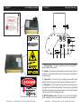
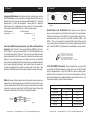
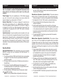
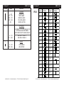
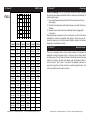
American DJ
®
Tri Fecta™ General Introduction
Introduction: Thank you for purchasing the American DJ® Tri Fecta.™
The Tri Fecta™ is a unique three color, DMX intelligent, laser effect
that creates different patterns. This unit can be used as a stand alone,
sound-active unit or in a Master/Slave configuration. The unit can also
be controlled via DMX controller. The unit’s sound sensitivity may be
adjusted by a sensitivity adjustment on the rear of the unit. The unit
may be mounted in either a horizontal or vertical position. For a dramatic laser show use several Tri Fectas™ together.
Unpacking: Every Tri Fecta™ has been thoroughly tested and has
been shipped in perfect operating condition. Carefully check the shipping carton for damage that may have occurred during shipping. If
the carton appears to be damaged, carefully inspect the unit for any
damage and be sure all accessories necessary to operate the unit have
arrived intact. In the event damage has been found or parts are missing, please contact our toll free customer support number for further
instructions. Please do not return the unit to your dealer without first
contacting customer support.
Customer Support: American DJ® provides a toll free customer sup-
port line, to provide set up help and to answer any question should
you encounter problems during your set up or initial operation. You
may also visit us on the web at www.americandj.com for any comments or suggestions. For service related issue please contact American DJ®. Service Hours are Monday through Friday 9:00 a.m. to 5:00
p.m. Pacific Standard Time.
Voice:
(800) 322-6337
Fax: (323) 582-2610
E-mail: [email protected]
To purchase parts online visit http://parts.americandj.com
Warning! To prevent or reduce the risk of electrical shock or fire, do
not expose this unit to rain or moisture.
User Instructions
Caution! There are no user serviceable parts inside this unit. Do not
attempt any repairs yourself, doing so will void your manufactures
warranty. In the unlikely event your unit may require service please
contact American DJ customer support.
PLEASE recycle the shipping carton whenever possible.
Rev. 10/09
©American
DJ® - www.americandj.com - Tri Fecta™ Instruction Manual Page 2
Tri Fecta™ General Instructions
Please carefully read and understand the instructions in this manual
thoroughly before attempting to operate this unit. These instructions
contain important safety information regarding the use and maintenance of this unit. Please keep this manual with the unit, for future
reference.
CAUTION IMPORTANT! When installing this projector, make sure
that it is mounted in a manner that prevents the audience from
looking directly into the beam, and the beam from striking the
audience.
Tri Fecta™ •
•
•
•
•
Features
4.9mW Red and Green Laser Diodes
Built-In Hanging Yoke
Sound Active with Internal Microphone
Fan Cooled
Music Sensitivity Knob
Tri Fecta™
Warranty Registration
The Tri Fecta™ carries a 90 day limited warranty. Please fill out the
enclosed warranty card to validate your purchase. All returned service
items whether under warranty or not, must be freight pre-paid and
accompany a return authorization (R.A.) number. If the unit is under
warranty you must provide a copy of your proof of purchase invoice.
Please contact American DJ® customer support for a R.A. number.
©American
DJ® - www.americandj.com - Tri Fecta™ Instruction Manual Page 3
Tri Fecta™ !
Safety Precautions
DANGER
VISIBLE LASER RADIATION
-AVOID DIRECT EYE EXPOSURE
LASER DIODE
WAVELENGTH : 635~650 nm
Max Output : <4.9mW
Class IIIa Laser Product
!
Safety Issues: This unit may “pop” the breaker if the maximum allotted
load of 2 amps is reached.
• To reduce the risk of electrical shock or fire, do not expose this unit
rain or moisture.
•Do not spill water or other liquids into or on to your unit.
•Do not attempt to remove or break off the ground prong from the
electrical cord. This prong is used to reduce the risk of electrical shock and fire in case of an internal short. Do not attempt to operate this unit if the power cord has been frayed or broken.
•Disconnect from main power before making any type of connection.
• Do not remove the cover under any conditions. There are no user serviceable parts inside.
•Always be sure to mount this unit in an area that will allow proper ventilation. Allow about 6” (15cm) between this device and a wall.
•Do not attempt to operate this unit, if it becomes damaged.
•This unit is intended for indoor use only, use of this product outdoors voids all warranties.
•During long periods of non-use, disconnect the unit’s main power.
•Always mount this unit in safe and stable matter.
•Power cords should be routed so they are not likely to be walked on, pinched by items placed upon or against them.
• Cleaning -The fixture should be cleaned only as recommended by the manufacturer. See page 18 for cleaning details.
•Heat -The appliance should be situated away from heat sources such as radiators, heat registers, stoves, or other appliances (including amplifiers) that produce heat.
•The fixture should be serviced by qualified service personnel when:
A. The power-supply cord or the plug has been damaged.
B. Objects have fallen, or liquid has been spilled into the unit.
C. The unit has been exposed to rain or water.
D. The unit does not appear to operate normally or exhibits a
marked change in performance.
©American
DJ® - www.americandj.com - Tri Fecta™ Instruction Manual Page 4
Tri Fecta™ Laser Warnings and Safety
NON-INTERLOCKED HOUSING WARNING
The Tri Fecta™ contains high power laser devices internally. Do not
open the laser housing, due to the potential exposure to unsafe levels
of laser radiation. The laser power levels, if the unit is opened, can
cause instant blindness, skin burns and fires.
STOP AND READ ALL LASER SAFETY DATA
OPERATION INSTRUCTIONS AND LASER SAFETY
Tri Fecta™ Laser Warnings and Safety
After setting up, and before public use, test laser to ensure proper
function. Do not use if any defect is detected. Do not use if laser
emits only one or two laser beams rather than dozens/hundreds, as
this could indicate damage to the diffraction grating optic, and could
allow emission of higher laser levels above Class 3R.
Do not point lasers at people or animals. Never look into the laser
aperture or laser beams.
The light source emitted from this product can potentially cause eye
injury if not set up and used properly. The light source emitted from a
laser is very different from any other light sources with which you may
be aware of. Laser light is thousands of times more concentrated
than any light from any other kind of light source. This concentration
of light can cause instant eye injuries, primarily by burning the retina
(the back of your eyeball contatining cells that are sensitive to light).
Even if you cannot feel “heat” from a laser beam, it can still potentially injure or blind you or your audience. Even very small amounts
of laser beam light are potentially hazardous even at long distances.
Laser eye injuries can be sustained faster than you can blink.
Do not point lasers in areas in which people can potentially get
exposed, such as uncontrolled balconies, etc.
Do not think that because this laser splits the laser beam into hundreds of beams and that the laser beam is scanned out in high
speed, that an individual laser beam is safe for eye exposure. This
laser uses dozens of milliwatts of laser power (Class 3B levels internally) before it splits into multiple beams (Class 3R levels). Many of
the individual beams are potentially hazardous to the eyes.
Do not use the laser if the housing is damaged, the housing is open,
or if the optics appear damaged in any way.
Do not that because the laser light is moving, it is safe. This is not
true. Nor, do the laser beams always move. Since eye injuries can
occur instantly, it is critical to prevent even the smallest possibility of
any direct eye exposure. In the laser safety regulation, it is not legal
to aim Class 3R lasers in areas which people can get exposed. This
is true even if it is aimed below people’s faces, such as on a dance
floor.
Do not operate the laser without first reading and understanding
all safety and technical data in this manual.
Always set up and install all laser effects so that all laser light is at
least 3 meters (9.8 feet) above the floor on which people can stand.
©American
DJ® - www.americandj.com - Tri Fecta™ Instruction Manual Page 5
Do not point lasers at highly reflective surfaces, such as windows,
mirrors and shiny metal. Even laser reflections can be hazardous.
Never point a laser at aircraft, this is a federal offense.
Never point un-terminated laser beams into the sky.
Do not expose the output optic (aperture) to cleaning chemicals.
Do not use laser if the laser appears to be emitting only one or two
beams.
Never open the laser housing. The high laser power levels inside of
the protective housing can start fires, burn skin and will cause instant
eye injury.
Never leave this device running unattended.
The operation of a class 3R laser show is only allowed if the show
is controlled by a skilled and well- trained operator, familiar with the
data included in this manual.
The legal requirements for using laser entertainment products vary
from country to country. The user is responsible for the legal requirements at the location/country of use.
Always use proper lighting safety cables when hanging lights and
effects overhead.
©American
DJ® - www.americandj.com - Tri Fecta™ Instruction Manual Page 6
Tri Fecta™ Laser Warninig Labels
Tri Fecta™ Control & Functions
3
A
M
P
1
DMX IN
DMX IN
SENSITIVITY
KNOB
MINI/C
REMOTE
ONLY
2
3
8
7
6
MIC
4
5
1.XLR Input Jack - This jack is used to accept an incoming DMX
signal or Master/Slave signal.
2.Breaker - A 3A built-in safety breaker to reduce the risk of electrical shock or fire and protect the circuitry. In the case of a internal short
or power surge.
3.Power Cord - Connect only to a matching power outlet. Never
usethis fixture is the ground prong has been removed or broken off.
4.Microphone - This microphone receives external low frequencies
to trigger the unit in Sound-Active mode. This microphone is designed
to receive low frequency sounds only, tapping on the microphone and
high pitch sounds may not trigger the unit.
5.Mini/C Controller Jack - This jack is for use with the optional
Mini/C controller only. Do not attempt to connect an audio signal to
©American
DJ® - www.americandj.com - Tri Fecta™ Instruction Manual Page 7
©American
DJ® - www.americandj.com - Tri Fecta™ Instruction Manual Page 8
Tri Fecta™ Control & Functions
this jack, this will damage the PC board and void your manufactures
warranty!
6.Audio Sensitivity Knob - This adjust audio sensitivity of the
internal microphone (4). Turning the sensitivity knob in the clockwise
direction will increase the sensitivity to sound. Turning the knob in
the counter clockwise direction will decrease the fixture’s sensitivity
to sound. If the knob is turned completely in the counter-clockwise
direction the sound sensitivity function will turn off.
7.Dip Switches - These switches serve two functions. In DMX mode
each switch corresponds to a specific value based on binary code.
See page 7 for a detailed explanation of DMX binary code.
8.XLR Output Jack - This jack is used to transmit the incoming
DMX s ignal to another DMX fixture, or transmit a Master/Slave signal
to the next Tri Fecta™ in the chain. For best results in DMX or Master/
Slave mode terminate this jack if it is the last unit in the chain. See
“Terminator” on page 12.
Tri Fecta™ Set Up
Power Supply: Before plugging your unit in, be sure the source volt-
age in your area matches the required voltage for your American DJ®
Tri Fecta.™ The American DJ® Tri Fecta™ is 120v only. Because line
voltage may vary from venue to venue, you should be sure your unit
voltages matches the wall outlet voltage before attempting to operate
you fixture.
DMX-512: DMX is short for Digital Multiplex. This is a universal pro-
tocol used as a form of communication between intelligent fixtures
and controllers. A DMX controller sends DMX data instructions from
the controller to the fixture. DMX data is sent as serial data that travels from fixture to fixture via the DATA “IN” and DATA “OUT” XLR terminals located on all DMX fixtures (most controllers only have a DATA
“OUT” terminal).
DMX Linking: DMX is a language allowing all makes and models of
different manufactures to be linked together and operate from a single controller, as long as all fixtures and the controller are DMX compliant. To ensure proper DMX data transmission, when using several
DMX fixtures try to use the shortest cable path possible. The order
in which fixtures are connected in a DMX line does not influence the
DMX addressing. For example; a fixture assigned a DMX address of 1
may be placed anywhere in a DMX line, at the beginning, at the end,
or anywhere in the middle. When a fixture is assigned a DMX address
of 1, the DMX controller knows to send DATA assigned to address 1
to that unit, no matter where it is located in the DMX chain.
Dipswitches in DMX mode: This unit uses dipswitches to assign a
DMX address. Each dipswitch represents a binary value.
Dipswitch 1 address equals 1
Dipswitch 2 address equals 2
Dipswitch 3 address equals 4
Dipswitch 4 address equals 8
Dipswitch 5 address equals 16
Dipswitch 6 address equals 32
Dipswitch 7 address equals 64
Dipswitch 8 address equals 128
Dipswitch 9 address equals 256
Dipswitch 10 - Some units omit dipswitch 10. When a unit does
include dipswitch #10, it is usually used for special functions such as
©American
DJ® - www.americandj.com - Tri Fecta™ Instruction Manual Page 9
©American
DJ® - www.americandj.com - Tri Fecta™ Instruction Manual Page 10
Tri Fecta™ Set Up
Tri Fecta™ sound activation.
Assigning DMX Address: Each dipswitch has a preset value. A specific DMX address is set by combining the dipswitches that sum your
desired value. For example: To achieve a DMX address of 7, combine
dipswitches 1, 2, and 3. Since dipswitch 1 has a value of 1, dipswitch
2 has a value of 2, and dipswitch 3 has a value of 4, the combination
of the three create a DMX value of 7. (See example below).
REMOTE
CONTROL
INPUT
SOUND
INPUT
OUTPUT
2
REMOTE
CONTROL
INPUT
INPUT
OUTPUT
REMOTE
CONTROL
INPUT
SOUND
INPUT
POWER
INPUT
OUTPUT
Pin 1 = Ground
REMOTE
SOUND
3 Hot
XLR Pin Configuration
1 Ground
INPUT
OUTPUT
PinCONTROL
2
= Data Compliment (negative)
INPUT
3 Hot
Pin 3 = Data True (positive)
Figure 3
Special Note: Line Termination. When longer runs of cable are
used, you may need to use a terminator on the last unit to avoid erratic
behavior. A terminator is a 90-120 ohm 1/4 watt resistor which is connected between pins 2 and 3 of a male XLR connector (DATA + and
DATA -). This unit is inserted in the female XLR socket of the last unit
in your daisy chain to terminate the line. Using a cable terminator (ADJ
part number Z-DMX/T) will decrease the possibilities of erratic behavior.
POWER
Data Cable (DMX Cable) Requirements (For DMX and Master/Slave
Operation): The Tri Fecta™ can be controlled via DMX-512 protocol.
The Tri Fecta™ is a three channel DMX unit. The DMX addressCOMMON
is set
on the side panel of the Tri Fecta.™ Your unit and
your
DMX
controller
DMX +
DMX512 OUT
XLR and data output
DMX require a standard 3-pin XLR connector for data3-PIN
input
(Figure 1). If you are making your own cables, be sure to use standard
two conductor shielded cable (This cable may be purchased at almost
all pro sound and lighting stores). Your cables should be made with
a male and female XLR connector on either end of the cable. Also
remember that DMX cable must be daisy chained and can not be split.
1
2 Cold
2 Cold
REMOTE
CONTROL
INPUT
SOUND
Set DMX address 1:
Set DMX address 7:
POWER
Dip-switches # 1 = 1
Dip-switches # 1 = 1
2=2
3 DMX512
=4
DMX+,DMX-,COMMON
=7
SOUND
XLR Female Socket
XLR Male Socket
1 Ground
Set Up
3
OUTPUT
SOUND
POWER
3
1
2
DMX512 IN
3-PIN XLR
3
REMOTE
CONTROL
INPUT
INPUT
1
2
OUTPUT
POWER
Termination reduces signal errors and
avoids signal transmission problems
and interference. It is always advisable
to connect a DMX terminal, (Resistance
120 Ohm 1/4 W) between PIN 2 (DMX-)
and PIN 3 (DMX +) of the last fixture.
Figure 4
5-Pin XLR DMX Connectors. Some manufactures use 5-pin XLR
connectors for DATA transmission in place of 3-pin. 5-pin XLR fixtures
may be implemented in a 3-pin XLR DMX line. When inserting standard 5-pin XLR connectors in to a 3-pin line a cable adaptor must be
used, these adaptors are readily available at most electric stores. The
chart below details a proper cable conversion.
POWER
Notice: Be sure to follow figures two and three when making your own
DMX512
DMX+,DMX-,COMMON
cables. Do not
use the ground lug on the XLR connector. Do not connect the cable’s shield conductor to the ground lug or allow the shield
conductor to come in contact with the XLR’s outer casing. Grounding
the shield could cause a short circuit and erratic behavior.
COMMON
DMX512 OUT
3-PIN XLR
1
2
3
DMX +
DMX -
3
1
2
DMX512 IN
3-PIN XLR
3
Figure 2
©American
1
2
3-Pin XLR to 5-Pin XLR Conversion
Conductor
3-Pin XLR Female (Out)
5-Pin XLR Male (In)
Ground/Shield
Pin 1
Pin 1
Data Compliment (- signal)
Pin 2
Pin 2
Pin 3
Pin 3
Termination reduces signal errors and
Data True (+ signal)
avoids signal transmission problems
and interference. It is always advisable
to connect a DMX terminal, (Resistance
Not Used
120 Ohm 1/4 W) between PIN 2 (DMX-)
and PIN 3 (DMX +) of the last fixture.
DJ® - www.americandj.com - Tri Fecta™ Instruction Manual Page 11
Not Used
©American
Pin 4 - Do Not Use
Pin 5 - Do Not Use
DJ® - www.americandj.com - Tri Fecta™ Instruction Manual Page 12
Tri Fecta™ Operation
CAUTION IMPORTANT! When installing this projector, make sure
that it is mounted in a manner that prevents the audience from
looking directly into the beam, and the beam from striking the
audience.
Power Supply: This unit is available only in 120v. Before plugging
your unit in be sure the source voltage in your area matches the
required voltage for your American DJ® Tri Fecta.™
General Operation: This fixture is designed to operate as a
stand alone, sound-active unit, or in a Master/Slave configuration.
It can also operate via DMX controller. The Tri Fecta™ is ready to
be plugged in out of the box. After plugging the power supply into
a power outlet, flip dipswitch #10 to the “ON” poition to activate
sound-active mode.
Sensitivity Knob: A sound sensitivity knob is located on the rear
of the unit. Use this knob to regulate the amount of sound it takes to
trigger the unit. Turning the knob in a clockwise direction will increase
the units sensitivity to sound, turning the knob in a counterclockwise direction will decrease the units sensitivity. Turning the knob
completely to the counter-clockwise direction will turn off the soundactive mode.
Operating Modes:
Universal DMX Control: This mode allows you to use a universal
DMX-512 controller such as the American DJ® DMX Operator™ or
Show Designer.™
1. To control your fixture in DMX mode, follow the set-up procedures
on pages 10-12 as well as the set-up procedures included with
your DMX controller.
2. For longer cable runs (more than a 100 feet) use a terminator on the last fixture.
3. The Tri Fecta™ uses three DMX channels. See pages 15-17 for detailed description of the DMX traits. Use your DMX control-
ler to activate the various built-in patterns.
4. For help operating in DMX mode consult the manual included with your DMX controller.
NOTE: If running in Master/Slave configuration while using a ©American
DJ® - www.americandj.com - Tri Fecta™ Instruction Manual Page 13
Tri Fecta™ Operation
DMX controller, the Master unit should have all dipswitches set to the “OFF” position. All slave units should have dipswitch #1 set to the “ON” position.
Stand-Alone Operation (Sound Active): This mode allows a
single unit to run to the beat of the music. Only use this mode when running a single unit, or when running several units as individuals.
1. Set dipswitch #10 to the “ON” positon to activate Stand-Alone. 2. The unit will react to the low frequencies of music via the internal microphone.
3. Use the audio sensitivity knob on the rear of the unit to make
the unit more or less sensitive to sound. Turning the sensitivity knob
in the clockwise direction will increase the sensitivity, turning the knob in the counter-clockwise direction will decrease the fixture’s sensitivity to sound.
4. The optional MINI/C Controller may be used with this mode to control a blackout function.
Master-Slave Operation (Sound Active): This mode will allow
you to link up to 16 units together and operate without a controller.
In Master-Slave mode, the units will react to sound. In Master-Slave
operation one unit will act as the controlling unit and the others will
react to the controlling units programs. Any unit can act as a Master
or as a Slave.
1. Using standard XLR microphone cables, daisy chain your units together via the XLR connector on the rear of the units. Remem-
ber the Male XLR connector is the input and the Female XLR connector is the output. For longer cable runs we suggest a terminator at the last fixture.
2. Choose a unit to function as the Master and set dipswitch #10 to the “ON” position. This unit must be the first unit in line. Then simply daisy chain the units together using XLR cables.
3. Turn dipswitch #1 to the “ON” position on the SLAVE units, and they will react the same as the MASTER.
4. Use the sensitivity knob on the rear of the master unit to make
it more or less sensative to sound.
5. The optional MINI/C Controller may be used to control a black-
out function.
©American
DJ® - www.americandj.com - Tri Fecta™ Instruction Manual Page 14
Tri Fecta™ Channel
Value
1
DMX Traits
Function
COLORS
0 - 63
64 - 127
128 - 191
192 - 254
255
2
LASER OFF
RED LASER
GREEN LASER
YELLOW LASER
SOUND ACTIVE
Tri Fecta™ FIG.1
Level
PATTERNS
0 - 110
111 - 255
3
SEE PAGES 14-15 FOR THE LIST OF
PICTURES AND PATTERNS
AND THEIR EXACT FADER LEVELS
SEE FIG.1 PAGE 14
SEE FIG.2 PAGE 15
SPEED
0 - 127
128 - 255
LOW SPEED
HIGH SPEED
Picture
Level
01-02
57-59
03-05
60-62
06-08
63-65
09-11
66-68
12-14
69-71
15-17
72-74
18-20
75-77
21-23
78-80
24-26
81-83
27-29
84-86
30-32
87-89
33-35
90-92
36-38
93-95
39-41
96-98
42-44
99-101
45-47
102-104
48-50
105-107
51-53
108-110
DMX Traits
Picture
54-56
©American
DJ® - www.americandj.com - Tri Fecta™ Instruction Manual Page 15
©American
DJ® - www.americandj.com - Tri Fecta™ Instruction Manual Page 16
Tri Fecta™ DMX Traits
Tri Fecta™ Cleaning
Fixture Cleaning: Due to fog residue, smoke, and dust cleaning
FIG.2
P6
P13
P20
P27
P34
P41
P48
P5
P12
P19
P26
P33
P40
P47
P4
P11
P18
P25
P32
P39
P46
P3
P10
P17
P24
P31
P38
P45
P2
P9
P16
P23
P30
P37
P44
P1
P8
P15
P22
P29
P36
P43
P0
P7
P14
P21
P28
P35
P42
Level
Point
Level
Point
Level
Point
111-113
P0
168-170
P19
225-227
P38
114-116
P1
171-173
P20
228-230
P39
117-119
P2
174-176
P21
231-233
P40
120-122
P3
177-179
P22
234-236
P41
123-125
126-128
P4
180-182
P23
237-239
P43
P5
183-185
P24
240-242
P44
129-131
P6
186-188
P25
243-245
P45
132-134
P7
189-191
P26
246-248
P46
135-137
P8
192-194
P27
249-251
P47
138-140
P9
195-197
P28
252-255
P48
141-143
P10
198-200
P29
144-146
P11
201-203
P30
147-149
P12
204-206
P31
150-152
P13
207-209
P32
153-155
P14
210-212
P33
156-158
P15
213-215
P34
159-161
P16
216-218
P35
162-164
P17
219-221
P36
165-167
P18
222-224
P37
©American
DJ® - www.americandj.com - Tri Fecta™ Instruction Manual Page 17
the internal and external lenses should be carried out periodically to
optimize light output.
1. Use normal glass cleaner and a soft cloth to wipe down the out-
side casing.
2. Clean the external optics with glass cleaner and a soft cloth every 20 days.
3. Always be sure to dry all parts completely before plugging the unit back in.
Cleaning frequency depends on the environment in which the fixture
operates (I.e. smoke, fog residue, dust, dew). In heavy use we recommend cleaning on a monthly basis. Periodic cleaning will ensure
longevity, and crisp beam output.
Tri Fecta™
Breaker Reset
This unit is equipped with a built-in safety breaker. This breaker is
designed to close the power circuit in the event of an internal short
or power surge. This will reduce the risk of electrical shock or fire and
protect the circuitry. To reset the breaker, push the breaker button in
until you hear it “pop” back in to place. If the breaker continues to
pop, stop using the unit and contact our customer support team, the
unit may need to be returned for service.
©American
DJ® - www.americandj.com - Tri Fecta™ Instruction Manual Page 18
Tri Fecta™ Warranty
MANUFACTURER’S LIMITED WARRANTY
A. American DJ, Inc. hereby warrants, to the original purchaser, American DJ and American
Audio products to be free of manufacturing defects in material and workmanship for a prescribed
period from the date of purchase (see specific warranty period on reverse). This warranty shall be
valid only if the product is purchased within the United States of America, including possessions
and territories. It is the owner’s responsibility to establish the date and place of purchase by acceptable evidence, at the time service is sought.
B.
For warranty service you must obtain a Return Authorization number (RA#) before
sending back the product. Contact American DJ, Inc. Service Department at 800-322-6337. Send
the product only to the American DJ, Inc. factory. All shipping charges must be pre-paid. If the
requested repairs or service (including parts replacement) are within the terms of this warranty,
American DJ, Inc. will pay return shipping charges only to a designated point within the United
States. If the entire instrument is sent, it must be shipped in it’s original package. No accessories
should be shipped with the product. If any accessories are shipped with the product, American DJ,
Inc. shall have no liability whatsoever for loss of or damage to any such accessories, nor for the
safe return thereof.
C. This warranty is void if the serial number has been altered or removed; if the product is
modified in any manner which American DJ, Inc. concludes, after inspection, affects the reliability
of the product; if the product has been repaired or serviced by anyone other than the American DJ,
Inc. factory unless prior written authorization was issued to purchaser by American DJ, Inc.; if the
product is damaged because not properly maintained as set forth in the instruction manual.
D.
This is not a service contract, and this warranty does not include maintenance, cleaning
or periodic check-up. During the period specified above, American DJ, Inc. will replace defective parts at its expense with new or refurbished parts, and will absorb all expenses for warranty
service and repair labor by reason of defects in material or workmanship. The sole responsibility
of American DJ, Inc. under this warranty shall be limited to the repair of the product, or replacement thereof, including parts, at the sole discretion of American DJ. All products covered by this
warranty were manufactured after January 1, 1990, and bear identifying marks to that effect.
Tri Fecta™ Specifications
Model: Tri Fecta™
Voltage*:
Lasers:
Breaker:
Dimensions:
Weight:
Duty Cycle:
Ventilation: Warranty:
120v~60Hz
4.9mW Red and Green Diodes
2A GMA
5.5” (H) x 4.7” (W) x 19.6” (L)
8.8 Lbs. (4kg)
None
Fan Cooled
90 Days
*Voltage is preset at the factory and can not be changed by the user.
Please Note: Specifications and improvements in the design
of this unit and this manual are subject to change without any
prior written notice.
E.
American DJ, Inc. reserves the right to make changes in design and/or improvements
upon its products without any obligation to include these changes in any products theretofore
manufactured. No warranty, whether expressed or implied, is given or made with respect to any
accessory supplied with products described above. Except to the extent prohibited by applicable
law, all implied warranties made by American DJ, Inc. in connection with this product, including
warranties of merchantability or fitness, are limited in duration to the warranty period set forth
above. And no warranties, whether expressed or implied, including warranties of merchantability
or fitness, shall apply to this product after said period has expired. The consumer’s and/or Dealer’s
sole remedy shall be such repair or replacement as is expressly provided above; and under no
circumstances shall American DJ, Inc. be liable for any loss or damage, direct or consequential,
arising out of the use of, or inability to use, this product. This warranty is the only written warranty applicable to American DJ and American Audio Products and supersedes all prior warranties and written descriptions of warranty terms and
conditions heretofore published.
MANUFACTURER’S LIMITED WARRANTY PERIODS:
• All American Audio Products = 1-year (365 day) Limited Warranty (except V-Plus Series Amplifiers)
• All American Audio V-Plus Series Amplifiers = 3-year (1095 day) Limited Warranty
• American DJ Lighting and American DJ Branded Products = 1-year (365 day) Limited Warranty
(Such as: Special Effect Lighting, Intelligent Lighting, UV lighting, Strobes, Fog Machines, Bubble
Machines, Mirror Balls, Par Cans, Trussing, Lighting Stands etc. excluding Laser Products, lamps,
and Star Tec Series)
• American DJ Laser Products and Star Tec Products = 90-Day Limited Warranty
• American DJ L.E.D. Products = 3-year (1095 day) Limited Warranty (excluding motors which
have a 1-year (365 day Limited Warranty)
©American DJ® - www.americandj.com - Tri Fecta™ Instruction Manual Page 19
American DJ®
American DJ World Headquarters:
6122 S. Eastern Ave. Los Angeles, CA 90040 USA
Tel: 323-582-2650 / Fax: 323-725-6100
Web: www.americandj.com / E-mail: [email protected]