1
WARNING This manual contains information on limitations regarding product use and function
and information on the limitations as to liability of the manufacturer. The entire manual should be
carefully read.
Maintenance
Manual
PC6010
Quick Reference Guide
This manual is for Supervisor and Master users. Each of
these types of user can access a different set of functions.
, and
symbols next to
The
the title of each procedure show which users can access
that function.
Each user should read all the sections that describe
the functions they can access. All users should read
pages 1-2 for important information on security
system operation.
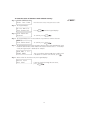
Main Menu:
This is the order of the prompts in the main menu. For
more information on each prompt, refer to the page
number indicated. Users will see only the prompts they
have access to.
Prompt
Page No.
Turn Areas On? ........................... User's Guide
Turn Areas Off? ..................... User's Guide
Delay Auto-Arm? ............................................ 5
To use any function:
End of basic user prompts
1. When the keypad is idle, it displays the time and
date:
Activate Door Strike? .......... User's Guide
Reset Detectors? ........................ User's Guide
12:00 2000/01/01
Enter Your Code
End of advanced user prompts
Enter your access code to go to the main menu.
Cancel Auto-Arm? ................................ 5
2. The keypad prompts you with questions about which
function you want to choose. See the appropriate
section for information on each function.
View Event Log? ........................................ 10
3. Press
Press
Change Keypad Setup? ............................ 20
to select a function
to skip to the next function.
or
4. Answer
questions until you are finished.
Change Access Codes? ............................ 14
End of supervisor user prompts
to each of the
Change Detector Setup? ......................... 8
View System Status? .............................. 11
Remember:
If you want to start over, press
at any time.
If you are viewing a list of items, the keypad displays a
flashing > when there is more information. Use
to see each item in the list.
View Detector Status? .......................... 12
Change Time and Date? .......................... 21
Perform System Test? ............................ 22
Allow System Service? .......................... 24
End of master (all) user prompts
End of List View List Again?
To return to the beginning of the prompts, press
.
To return to the start screen, press
.
Table of Contents
Keypad Buttons and Lights
2
1 About Your Security System
3
1.1 Using This Manual ................................................................................................................................................ 3
1.2 Understanding Your Security System .................................................................................................................. 3
1.3 Remote Monitoring .............................................................................................................................................. 4
2 Turning Off Automatic Arming
5
3 Using Access Cards
7
4 Changing the Setup of Detectors
8
4.1 Bypassing and Disabling Detectors .................................................................................................................... 8
4.2 "Warning-Security Reduced" Message ............................................................................................................... 9
5 Viewing Events and System Status
10
5.1 Viewing the Event Log ....................................................................................................................................... 10
5.2 Viewing the Status of the System ..................................................................................................................... 11
5.3 Viewing and Resetting System Faults ............................................................................................................... 13
6 Programming Access Codes & Cards
14
6.1 Program A New Access Code .............................................................................................................................
6.2 Erase Code ...........................................................................................................................................................
6.3 Edit User Name ...................................................................................................................................................
6.4 Creating a Duress Code ......................................................................................................................................
6.5 Programming an Access Card ............................................................................................................................
6.6 Programming a Code Schedule .........................................................................................................................
6.7 Programming a Card Access Level .....................................................................................................................
6.8 Enabling and Disabling Access Cards ................................................................................................................
6.9 Assigning Areas to a User ..................................................................................................................................
6.10 Changing Options for an Existing Code ...........................................................................................................
6.11 Walk Test Code ....................................................................................................................................................
7 Changing System Settings
15
16
16
17
17
17
18
18
18
19
19
20
7.1 Changing Keypad Settings ................................................................................................................................. 20
7.2 Changing the System Time and Date ................................................................................................................ 21
8 Testing and Maintenance
22
8.1 Testing Your Security System ............................................................................................................................. 22
8.2 Allowing System Service .................................................................................................................................... 24
Glossary
25
Special Character Chart
26
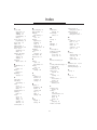
Index
27
Limited Warranty
28
Warning Please Read Carefully
inside back cover
1
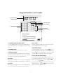
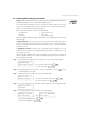
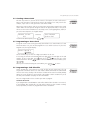
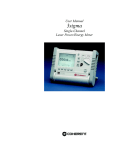
Keypad Buttons and Lights
1. Liquid Crystal
Display (LCD)
3. System Lights
4. Arrow Keys
2. Number Pad
5. Yes, No
& Cancel Keys
1. Liquid Crystal Display (LCD):
Power Light
The LCD displays prompts and system information on
two 16-character lines. This diagram shows the Start
Screen.
The Power light will always be on, unless the system or
one of the modules has lost AC power.
2. Number Pad:
If you are viewing items in a list, use the
keys to
move forward to the next item, or back to the previous
item. If there is more information to view, the keypad
will flash a > in the top right corner of the display.
4. Back/Next Keys:
Use the number pad to enter your access code.
3. System Lights:
The On and Off lights will only be lit as described after
you have entered a valid access code. If no code has
been entered, only the Power light will be on.
5. Yes, No and Cancel Keys:
For each feature, the system will display a question (e.g.
Do you want to turn areas on?). Press
to
answer yes and
to answer no.
Off Light
When you are turning areas on or off, the Off light will
turn on to tell you that the area displayed is currently off.
If you are unsure, or have lost your place in the system
programming, press
to return to the start
screen ("Enter Your Code").
On Light
When you are turning areas on or off, the On light will
turn on to tell you the area displayed is currently on.
2
About Your Security System
S
E
C
T
I
O
N
1
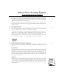
Your DSC security equipment has been designed to give you the greatest possible flexibility
and convenience. The liquid crystal display (LCD) keypad guides you through each operation
with easy-to-understand prompts. With unique sound sequences, the keypad signals
faults and other indications of system status.
Read this manual carefully to become familiar with the features that have been
implemented on your system. All users of this system should be instructed in the features
available to them.
1.1 Using This Manual _______________________________________________________________
There are 4 possible types of users of an PC6010 security system. Each of the 4 user types
can access different levels of features, as described in section 6.
This manual describes how to use the features that are available only to Supervisor and
Master users. For information on Basic and Advanced user functions (which are also
available to Supervisor and Master users), please refer to the User's Guide.
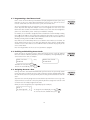
Each user type has access to a different set of system functions. Each procedure indicates
which users will be able to access it, with a graphic similar to the following:
1.2 Understanding Your Security System ___________________________________________
Your security system is made up of a control panel, keypads, and various detectors and
sensors.
Control Panel
The control panel is the “brain” of your security system. It controls and monitors all the
keypads and sensors, and communicates with the central station (if remote monitoring is
turned on). The control panel will be mounted out of the way, in a utility closet or in a
basement. The metal cabinet contains the system electronics, fuses, and stand-by battery.
There is normally no reason for anyone but the installer or service professional to have
access to the control panel.
Keypads
You can access system functions with your keypad(s), described in the User's Guide.
Each keypad has a sounder. The keypad has a liquid crystal display (LCD) which shows
system messages. The keypad can send commands to the system and show the current
system status. Your installer will mount the keypad(s) inside your premises, close to the
entry/exit door(s).
3
Zones and Areas
The security system has several zones (monitored areas). Each of these zones will be
connected to a sensor (motion detectors, glassbreak detectors, door contacts, etc.). If a
sensor goes into alarm, the keypad displays a message (i.e. zone in alarm).
Your installer may have divided the system into different areas. Each area includes one or
more zones, and can be turned on and off independently of other areas. Your installer
should explain to you which areas have been programmed, and which zones belong to
which areas.
Access Codes
As a user of the system, you will be assigned a 4- or 6-digit access code. You can use your
access code to turn areas on and off, and to access other system functions.
Your access code may not allow you to use certain system functions. For instance, if your
code is only allowed to turn on area 1, you will not be able to turn on other areas. For
more information on access codes and how to program them, please see section 6.
1.3 Remote Monitoring _____________________________________________________________
The system can send alarms, troubles and emergency messages over telephone lines to a
central station. If you accidentally initiate an alarm, immediately call the central station to
prevent an unnecessary response.
NOTE: Your installer must enable monitoring for it to work.
IMPORTANT NOTICE
A security system cannot prevent emergencies. It is only intended to alert you and – if included – your
central station of an emergency situation. Security systems are generally very reliable but they may not
work under all conditions and they are not a substitute for prudent security practices or life and property
insurance. Your security system should be installed and serviced by qualified security professionals who
should instruct you on the level of protection that has been provided and on system operations. For
important warnings and cautions, please see inside the back cover.
4
Turning Off Automatic Arming
S
E
C
T
I
O
N
2
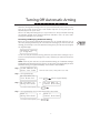
Automatic arming (auto-arming) is when the system automatically turns on one or more
areas of the system at preset times. Your installer may have set up your system to
automatically arm at specific times.
All users can delay auto-arming for a pre-set period of time. Ask your installer how long
the automatic arming will be delayed. Supervisor and Master users can cancel autoarming until midnight of the same day.
Cancelling and Delaying Automatic Arming
Before the system begins automatically arming an area, the keypads will warn users in
the area by beeping continuously (this is the auto-arm warning). If you hear the auto-arm
warning, you can delay or cancel the automatic arming. Enter your code at an area keypad.
The keypad displays:
Automatic Arming
in Progress!
To cancel or delay the automatic arming, follow the procedure below starting at step 3.
To cancel or delay automatic arming before it starts, follow the procedure below from the
beginning.
NOTE: If none of your areas are set up for automatic arming, or if automatic arming is
already delayed or cancelled, or if the system is set up so that users cannot delay or cancel
automatic arming, the keypad will display "This Function is Not Available".
Step 1. 12:00 2000/01/01
Enter Your Code
From the start screen, enter your access code.
Step 2. The keypad displays:
Do You Want To
Turn Areas On?
Step 3. Do You Want to
Press
or
Delay Auto-Arm?
until the keypad displays:
Do You Want to
Cancel Auto-Arm?
To confirm either option, press
Step 4. The keypad displays the first area which will be auto-armed:
Area 1!
Delay Auto-Arm?
or
To confirm either option, press
Area 1!
Cancel Auto-Arm?
.
5
Step 5. The keypad displays:
Automatic Arming
Has Been Delayed
or
Automatic Arming
is now Cancelled
If you have delayed automatic arming, the system will try again to arm the system at
the end of the delay time programmed by your installer.
If you have cancelled automatic arming, automatic arming will work again, as scheduled,
starting the following day.
If there are more areas that will be auto-armed, the keypad displays the next area.
Step 6. At the end of the list of areas, the keypad displays:
End of List
Exit Now?
To return to the list of areas, press
.
To return to the start screen, press
.
6
Using Access Cards
S
E
C
T
I
O
N
3
NOTE: This section only applies to systems that have card readers and the PC6820 access
control module installed. Talk to your installer for information regarding the access control
capabilities of your system.
If your system has access control capabilities, instruct your users on the use of their access
cards. All four types of users may use access cards.
Using Your Access Card
To gain access to an area via a door with an access card reader, present your access card
to the reader. Depending on the type of reader, this may mean "swiping" your card
through the reader, or just holding your card in front of the reader. The system will either
grant or deny you access to the protected area, depending on how your card has been
programmed.
Most access card readers will have a status light. This light will indicate your access status
once the card is presented. The light will appear according to the following conditions:
• Steady red light: The door is locked.
• Steady green light: The door is unlocked.
• Slowly flashing from red to green: The area is turned on.
• Flashing from red to green twice per second: The reader is waiting for a second card
to be swiped.
• Flashing from red to green three times per second: Access is denied.
Some access card readers also have audible indicators which beep under certain conditions.
The reader may beep when an access control door has been left open too long, or when
a door has been forced open.
Turning Areas On and Off Using an Access Card
You may be able to automatically turn your areas on and off using your access card. Ask
your installer if this feature has been enabled.
To turn an area on using an access card, ensure that the area is secured. Close all protected
doors and cease movement in areas covered by motion detectors. Swipe the access card
in the reader. Push the “Arm” button. The exit delay will begin.
To turn an area off, present the access card to the reader. The area may turn off, if the
system allows. If disarming is granted, the door will unlock. When you open the door, the
system will turn the area off.
To program access cards for your users, please see section 6.
7
Changing the Setup of Detectors
S
E
C
T
I
O
N
4
If you will need access to a protected area (i.e. a part of the premises covered by a detector)
while the system is armed, or if a detector is not working, you can either bypass or disable
the detector.
When you tell the system to bypass a detector, it will exclude the selected detector from
the armed areas the next time the system is armed. Bypassed detectors will not be able to
sound an alarm. The bypasses on the detectors are automatically cancelled each time the
system is disarmed. If you want the system to bypass the detectors again, you must set
the detectors to bypass before the next arming.
When you tell the system to disable a detector, it will exclude the detector from the
system until you turn it back on again. Disabled detectors will not be able to sound
alarms, tamper conditions, or faults.
NOTE: Bypassing and disabling detectors reduces your security protection. If you are
bypassing a detector because it is not working, call a service technician immediately so
that the problem can be resolved and your system returned to proper working order.
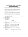
4.1 Bypassing and Disabling Detectors _____________________________________________
To bypass or disable one or more detectors:
Step 1. 12:00 2000/01/01
Enter Your Code
From the start screen, enter your access code.
Step 2. The keypad displays:
Do You Want To
Turn Areas On?
Press
until the keypad displays:
Step 3. Change Detector
Setup?
To confirm, press
.
Step 4. The keypad displays the first area where you can bypass or disable detectors, for
example:
Area 1
In This Area?
If the detector is in this area, press
.
Step 5. The keypad displays the first detector you can bypass or disable, for example:
ZONE 1
Select Detector?
To select the detector, press
.
Step 6. The keypad displays the current status of the detector (i.e. normal, disabled, or
bypassed), for example:
ZONE 1
Is Normal
>
To view the available options for the detector, press
8
.
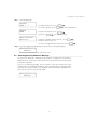
4: Changing the Setup of Detectors
Step 7. The keypad displays
Disable
ZONE 1 ?
Bypass
ZONE 1
To disable the detector, press
To see more options, press
?
Select Another
Detector?
.
. The keypad displays
To bypass the detector, press
.
If you press
, the keypad prompts
To bypass or disable another detector, press
and then repeat steps 5 to 7.
To exit the Change Detector Setup menu, press
,
.
Step 8. If you have bypassed or disabled any of the detectors, the keypad displays:
Warning-Security
Reduced
for a few seconds, then returns to the start screen.
4.2 "Warning-Security Reduced" Message __________________________________________
The system will display the "Warning-Security Reduced" message when you bypass or
disable detectors, or if you try to turn on areas of the system when there are open zones
or detectors with faults.
If you see the following message, you can continue to turn your area(s) on, but you
should contact your installation company to get the problem detectors working as soon
as possible. See section 2.4 of the User's Guide for more information on turning areas on
when zones are open or detectors have faults.
Warning-Security
Reduced
9
Viewing Events and System Status
S
E
C
T
I
O
N
5
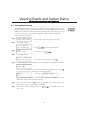
5.1 Viewing the Event Log __________________________________________________________
The PC6010 system keeps a record of up to 2500 system events in the Event Log. You can
view the recorded events on the keypad from most recent (number 0001) to oldest (number
2500). If your installer has connected a printer to your system, the system may be set up
to print events as they occur. Ask your installation company for more information.
To view events at the keypad:
Step 1. 12:00 2000/01/01
Enter Your Code
From the start screen, enter your access code.
Step 2. The keypad displays:
Do You Want To
Turn Areas On?
Press
until the keypad displays:
Step 3. View
Event Log?
To confirm, press
.
Step 4. The keypad displays:
Scroll...Bck/Nxt
Press No to Exit
To view the most recent event, press
.
Step 5. The keypad displays the time and date of the event and the event number, for example:
15:16 1999/03/03
Event 0001
*
When you see a flashing *, there is more information regarding the event. Press
to see the next screen. For example, the keypad may display:
AREA 1
User 1
and then,
Keypad Login
*
Most event log messages are self-explanatory. If you see a message you do not
understand, contact your installation company.
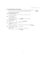
Step 6. To view the next event, press
. To skip to a particular event number, enter the 4digit number (e.g. to see event 200, enter [0200]).
Step 7. When you are finished viewing events, press
. The keypad returns to the
start screen.
10
5: Viewing Events and System Status
5.2 Viewing the Status of the System _______________________________________________
Master users can view the current status (on or off) of each area on the system, and of
each system detector with reduced security (trouble, fault, disabled or bypassed).
To view the status of each area:
Step 1. 12:00 2000/01/01
Enter Your Code
From the start screen, enter your access code.
Step 2. The keypad displays:
Do You Want To
Turn Areas On?
Press
until the keypad displays:
Step 3. View System
Status?
To confirm, press
.
Step 4. The keypad displays the first area and its status:
AREA 1
is Off... Next?
To view the status of the next area, press
Step 5. At the end of the list of areas, the keypad displays:
End of List
Exit Now?
If you are finished viewing area status,
press
.
11
.
To view the status of detectors with reduced security:
Step 1. 12:00 2000/01/01
Enter Your Code
From the start screen, enter your access code.
Step 2. The keypad displays:
Do You Want To
Turn Areas On?
Press
until the keypad displays:
Step 3. View Detector
Status?
To confirm, press
.
Step 4. The keypad displays the first area and asks if you want to view the detectors:
AREA 1
View Detectors?
To confirm, press
.
Step 5. The keypad displays the first detector with reduced security. The keypad displays letters
beside the detector label, which indicate the status of the detector (i.e. T = trouble, F
= fault, B = bypassed, D = disabled). For example:
Zone 001 T
FRONT DOOR
D >
This screen shows that zone 001 has a trouble, and
is disabled. To view the next detector, press
.
Step 6. At the end of the list of detectors, the keypad displays:
End of List
Exit Now?
If you are finished viewing detector status,
press
.
12
5: Viewing Events and System Status
5.3 Viewing and Resetting System Faults ___________________________________________
NOTE: A fault condition reduces the security your system is designed to provide. Call your
installation company or service technician to arrange service.
The control panel continuously checks for a number of possible faults. If one of these
faults occur, the keypad beeps twice every 10 seconds. To see a list of system faults, enter
your access code and follow the procedure below.
Basic users will only be able to view the following faults:
• Telephone line
• Seismic detector test
• Battery
• Fire trouble
• AC power
• General System Fault
The system will give Advanced, Supervisor and Master users additional information in the
fault messages.
If (AC) Power Fault is present, the system has lost its power. This trouble may be due to
a power outage and should be cleared once the power is restored. If the power on the
premises is running normally and the trouble condition persists, call your installation
company for service.
If Telephone Line Fault is present, there is a problem with the telephone line. If the
telephones on the premises are running normally and the trouble condition persists, call
your installer for service.
Any other trouble condition will require the assistance of your installation company. As
soon as a trouble condition occurs, call your installation company or service technician to
have the problem corrected.
Step 1. After you have entered your access code, if there is a fault, the keypad displays:
System Fault
View Fault List?
To exit fault viewing, press
To view faults, press
.
.
Step 2. The keypad displays the list of faults. If you see a flashing >, use the
keys to
scroll through the list of faults.
Step 3. When you come to the end of the list, the keypad displays:
End of List
Clear Faults?
To return to the main menu, press
To clear the faults, press
.
.
Step 4. The system attempts to reset the faults. If all the faults are reset, the keypad displays:
Fault(s) Now
Cleared!
Step 5. If the system cannot reset all the faults, the keypad displays:
Unable to Clear
All Fault(s)!
then,
Call for Service
Exit Now?
To view the faults again, press
To exit fault viewing, press
.
.
13
Programming Access Codes & Cards
S
E
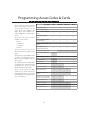
Access codes are used to turn the
system on and off, as well as to
access system functions. Access
codes can be either 4-digits or 6digits. Talk to your installer if you
require 6-digit access codes on your
system.
There are four types of codes
available on the system.
• Basic
• Advanced
• Supervisor
• Master
These users have access to the
functions listed in the table on the
right.
Supervisor users can program codes
for Basic and Advanced users.
Master users can program codes for
all user types.
The following sections explain how
to program new codes and modify
existing codes. All access code
options will also be described.
Your security system may also
include access control with access
cards and card readers. If so, you can
also program access cards for each
user. See section 6.5.
C
T
I
O
User Types:
N
6
Basic
Advanced
Supervisor
Master
Arm (Assigned Areas)
Y
Y
Y
Y
Disarm (Assigned Areas)
Y
Y
Y
Y
Silence Siren/Bell (Assigned
Areas)
Y
Y
Y
Y
View Alarms (Assigned
Areas)
Y
Y
Y
Y
Acknowledge/Clear Alarms
(Assigned Areas)
Y
Y
Y
Y
View Open Zones (Assigned
Areas)
Y
Y
Y
Y
Bypass/Disable Zones on
Arming (Assigned Areas)
Y
Y
Y
Y
View and Clear Basic Faults
Y
N
N
N
View and Clear Advanced
Faults
N
Y
Y
Y
Delay Automatic Arming
Y
Y
Y
Y
Y
Y
Activate Doorstrike
N
Y
Reset Detectors
N
Y
Y
Y
Cancel Automatic Arming
N
N
Y
Y
View Event Buffer/Log
N
N
Y
Y
Bypass and Disable Zones (All
Areas, at Any Time)
N
N
N
Y
View System Status (All
Areas)
N
N
N
Y
Change Access Codes (Only
Codes in a Lower User Type)
N
N
Y
Y
Change Keypad Setup
N
N
Y
Y
Change Time & Date
N
N
N
Y
Perform System Test
N
N
N
Y
Allow System Service
N
N
N
Y
14
6: Programming Access Codes and Cards
6.1 Program A New Access Code ____________________________________________________
To program a new access code, perform the following steps:
Step 1. 12:00 2000/01/01
Enter Your Code
Step 2. Press
From the start screen, enter your access code.
until the keypad displays:
Change
Access Codes?
To confirm, press
.
Step 3. The keypad displays the number of access codes free for programming, and then:
Do You Want To
Add a New User?
To confirm, press
.
To confirm, press
.
Step 4. The keypad displays:
Program Next
Available User?
Step 5. The keypad displays the next available user, for example:
User 2
Edit User Type?
Each new user is a basic user by default.
To program a user of a different type, press
.
Step 6. Use the
buttons to scroll through the available user types. When you see the
user type you want, press
.
Step 7. The keypad displays:
User 2
Edit User Type?
If the user type is correct, press
.
Step 8. The keypad displays:
User 2
Program Code?
To program the access code, press
enter the 4-digit, or 6-digit code.
, then
NOTE: Do not program access codes that can be easily guessed and will compromise the
security of your system (e.g. 1111 or 1234).
Your system may warn you when you program a code that is already used in the
system. Ask your installer if this feature is working on your system. If the feature is
working and you program a duplicate code, the keypad sounds an error tone and
displays:
Error - Code
Exists
and then,
User 2
Program Code?
Repeat step 8 to program a unique code.
Step 9. When you have completed programming the user code, you can use the
to
scroll to other options that you can program for the user. Each of these options are
described in sections 6.2 to 6.9.
15
6.2 Erase Code ______________________________________________________________________
Erase Code?: If you select this function, the keypad displays:
Press (YES) to
Erase code...
To confirm, press
.
The system erases the 4- or 6-digit code. The system keeps the rest of the user's
programming in memory.
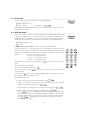
6.3 Edit User Name __________________________________________________________________
Edit User Name?: If you select this function, you can change the label for the user
(e.g. you can change "User 2" to "Jane Smith". The user name label is displayed on the
keypad when you are editing access codes, or when you are reviewing the event log. You
will also be able to search for a user with the user name label. The keypad displays:
Program Name
User 2
*
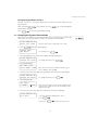
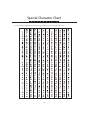
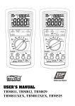
Enter the new user name using the number keys in the following manner:
Pressing number keys 1 - 9 will enter the letters of the alphabet (in upper-case letters).
Each key can enter 3 different letters and a number, depending on the number of times
you press it. The diagram on the right shows the number keys that will enter each letter.
Example:
To enter “A”, press [1] one time
To enter “B”, press [1] two times
To enter “C”, press [1] three times
To enter "1", press [1] four times
to move the cursor to the next
When you have entered the letter you want, press
space.
To enter a blank space, press [0].
To move the cursor back a space, press
To erase a character, use the
press the [0] key.
.
keys to move the cursor under the character, then
If you press the
key, the system provides additional label-entry options. Use the yes
and no keys to select the option you want.
The available options are:
• Clear Display?: To erase the entire label, press
.
• Clear to End?: To erase the label from the character where the cursor was
located to the end of the display, press
.
• Change Case?: To change the case of the letters you enter, press
.
• Enter ASCII?: To enter uncommon characters, press
.
Use the
keys to scroll through the available characters. Each character will
be displayed along with the corresponding 3-digit ASCII number. If you know the
character’s 3-digit number, you can enter it. To enter the character into the label,
press
. See Appendix A at the back of this manual for a list of the
available ASCII characters.
16
6: Programming Access Codes and Cards
6.4 Creating a Duress Code _________________________________________________________
Duress Options?: If you turn on the “Duress” user option, the code can become a
Duress code. The Duress code will be the same as the regular access code, plus one (for
example, if your code is 1234, your Duress code will be 1235).
When a user enters a duress code, the security system sends a duress signal to the central
station. Make sure that you also assign the code to the appropriate areas, or the system
will not see the code as valid when it is entered by a user. (See Assigning Areas, below.) If
you select Duress Options, the keypad displays:
Duress is now
Off
Turn Duress
Option On?
and then,
To turn on the duress option, press
.
6.5 Programming an Access Card ___________________________________________________
Program Card?: Your security system may also include access control with access cards
and card readers. If so, you can also program an access card for each user. If you select
Program Card, the keypad displays:
Enter Card # *
0000000
Use the number keys to enter the 7-digit card number for the user.
If necessary, you can also enter hexadecimal (hex) digits in the first two digits of the card
number. To enter a hex digit, press
, then press
. You can enter a hex
number from A to F. Use the
keys to scroll to the number. To select a number, press
.
When you are finished entering the card number, press
to save it.
6.6 Programming a Code Schedule __________________________________________________
Code Schedule?: If you want access codes to work at only certain times, you can
assign a date schedule to each access code. A date schedule will include the start and end
times for each event, the days of the week the schedule will be active for and any holiday
groups the event will observe. Your installer can program custom schedules for you to
use. Ask your installation company for more information.
Enter the 2-digit number of the schedule you want to program.
Schedules 00 and 01
If you program date schedule 00, the code will be disabled (this schedule is never active).
If you program date schedule 01, the code will be always on (this schedule is always
active). By default, all codes are programmed for date schedule 01.
17
6.7 Programming a Card Access Level _______________________________________________
Edit Card Access: When your installation company programmed your system, they
may have set up access control doors with different levels of access. You can use access
levels to control who can enter areas of the system, and at what times.
Access levels will allow specific users to have access to areas of the system at various times
of the day. Each door may have multiple access levels assigned to it. Each access level
follows one date schedule. For information on which access levels have been assigned to
your access control doors, please contact your installation company.
For example, access level 02 is assigned to a date schedule that is active Monday to Friday,
from 8:00 am to 5:00 pm. The installer has assigned the front door to access level 02. If
you assign user 2 to access level 02, that user will only be able to enter the front door from
Monday to Friday, between 8:00 am and 5:00 pm.
Users with access level 01 always have access to all doors. Users with access levels 02 - 63
will be allowed entry by the access door only during the times that the assigned date
schedule is active. Users with access level 00 will never be allowed entry by any of the
access control doors.
Enter the 2-digit number of the access level you want to program.
6.8 Enabling and Disabling Access Cards ____________________________________________
Card Options?: In order for a user's card to work on the system, it must be enabled.
New user cards are enabled by default. If you select Card Options, the keypad displays the
current status of the card, for example:
Card is Now
Enabled
Make the Card
Disabled?
then,
To disable the card, press
To leave the card enabled, press
.
.
6.9 Assigning Areas to a User _______________________________________________________
Assign Areas?: Your installer has divided the system into areas. The system may contain
one or more areas. In order for an access code to function, you must program which areas
the code will be active on. If your system only has one area, you must activate the code for
area 1.
Supervisor users can only assign users to areas that the supervisor has access to (e.g. if the
supervisor has access to areas 1 and 2, they will only be able to assign users to areas 1 and
2.) Master users are always assigned to all areas.
When you select Assign Areas, the keypad displays (for example):
Area 1
Is Assigned?
>
N
To assign the area displayed, press
To scroll to the next available area, press
18
.
.
6: Programming Access Codes and Cards
6.10 Changing Options for an Existing Code _________________________________________
To change the options for an existing code, you must first search for it using one of three
methods: by user number, by card number, or by user name. To change an existing code:
Step 1. 12:00 2000/01/01
Enter Your Code
Step 2. Press
From the start screen, enter your access code.
until the keypad displays:
Change
Access Codes?
To confirm, press
.
Step 3. The keypad displays the number of access codes free for programming, for example:
0999 Users Free
1000 Users Total
Press
and then,
Do You Want To
Add a New User?
.
Step 4. The keypad displays:
Do You Want To
Change a User?
To confirm, press
.
Step 5. Select a search method. There are three ways you can search for a user code to edit:
Search By Num?: Select this option to search for a user by user number. Enter the
4-digit user number for the user you want to change, or use the
keys to scroll
to the user you want.
.
When you see the user number you want, press
Search By Card?: Select this option to search for a user by access card number.
Enter the 7-digit card number for the user you want to change.
Search By Name?: Select this option to search for a user by user name. Enter all,
or part of the name for the user you want. The system will display the first
.
matching name. To confirm that this is the correct name, press
Step 6. To confirm that you have found the correct user, press
again.
The keypad displays (for example):
User 2
Edit User Type?
You can now edit any of the user options, as described in sections 6.1 to 6.9.
6.11 Walk Test Code __________________________________________________________________
You can use the walk test code to perform a walk test of your security system. See section
8.1 for instructions on performing a walk test. The walk test code is programmed by your
installer. Talk to your installer for more information regarding this code.
19
Changing System Settings
S
E
C
T
I
O
N
7
7.1 Changing Keypad Settings ______________________________________________________
Supervisor and Master users can change four keypad settings: the door chime setting,
keypad display brightness, keypad display contrast, and keypad buzzer volume. These
settings can be changed at each system keypad. To change any of these settings:
1.
12:00 2000/01/01
Enter Your Code
2. Press
From the start screen, enter your access code.
until the keypad displays:
Change Keypad
Setup?
To confirm, press
.
3. The keypad displays the beginning of the keypad setup menu.
keys to scroll to the keypad setting you want to change, and then
Use the
press
. Each of the four settings is described below.
Changing the Door Chime Setting
Door Chime Control?: If you turn this feature on, the keypad will beep five times
when selected zones are opened or closed. This feature is normally used to notify users
when entry/exit doors are opened and closed. Ask your installer which zones will activate
the door chime.
to the prompt, press
After answering
chime on or off.
again to turn the door
Changing Keypad Brightness
Brightness Control?: This option allows you to control how bright the keypad
backlighting will be when the keypad is not in use.
to the prompt, press
After answering
to decrease the backlighting.
Press
to increase the backlighting, or
to save the backlighting setting.
Changing Keypad Contrast
Contrast Control?: This option allows you to control how much contrast there is on
the keypad display.
After answering
decrease the contrast.
Press
to the prompt, press
to increase the contrast, or
to save the contrast setting.
20
to
7: Changing System Settings
Changing Keypad Buzzer Volume
Buzzer Control?: This option allows you to control the volume and tone of the
keypad buzzer.
After answering
keypad buzzer options.
Press
to the prompt, press the
keys to scroll through the
to save the keypad buzzer setting.
7.2 Changing the System Time and Date ____________________________________________
Master users can change the system time and date. If the security system loses power, you
may need to reset the system time and date. To change the time and date:
1.
12:00 2000/01/01
Enter Your Code
2. Press
From the start screen, enter your access code.
until the keypad displays:
Change Time
And Date?
To confirm, press
.
3. The keypad displays the current time and date setting and prompts:
12:00 2000/01/01
Change The Time?
To change the time, press
.
4. The keypad displays:
Set 24hr Time
Enter HHMM 1200
Enter the current time in 24-hour format (e.g. to
enter 1:00 pm, enter [1300]).
5. As soon as you enter all 4 digits, the keypad saves the entered time and displays:
13:00 2000/01/01
Change The Date?
To change the date, press
.
6. The keypad displays:
Set Date
(YYMMDD)
000101
Enter the current date: enter the last 2 digits of the
current year, 2 digits for the current month, and 2
digits for the day.
7. As soon as you enter all 6 digits, the keypad saves the date and displays:
13:00 2000/01/01
Exit Now?
If the time and date displayed are correct,
press
.
If not, press
and repeat steps 3 to 6.
21
Testing and Maintenance
S
E
C
T
I
O
N
8
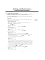
8.1 Testing Your Security System ___________________________________________________
NOTE: You should test your system every week. If there are any trouble conditions on the
system, call your installation company or service technician immediately.
There are two features that allow you to test that your security system is working properly:
the system test, and the walk test.
System Test
Master users can conduct a test of the system bells, system lights, and telephone
communications. To begin the system test:
1.
12:00 2000/01/01
Enter Your Code
2. Press
From the start screen, enter your access code.
until the keypad displays:
Perform System
Test?
To confirm, press
.
To confirm, press
.
3. The keypad displays:
Start
Bell Test?
4. The keypad displays:
Test All
Your Areas?
To test all the areas, press
To test the bells in only a certain area, press
scroll to the area you want to test.
5. After you select area(s) to test, the keypad displays:
.
, then use the
keys to
Test in
Progress!
The system will sound all the bells and keypad buzzers in the selected area(s) for 2
seconds. The lights on the keypad will light up, and the keypad display will show solid
blocks.
If any bells in the selected area(s) did not sound, or if the keypads are not working
correctly, contact your installation company. You can now either exit the bell test menu
at the prompt), or select another
and select another test to perform (press
area to test (press
at the prompt).
6. To test the lights on all system annunicators, answer
to:
Start
Lamp Test?
22
8: Testing and Maintenance
7. The system will attempt to turn on all the lights on all the system annunciators. The
lights will be on for 2 seconds. When the test is complete, the keypad displays:
Test Complete!
If any lights did not work during the test, contact your installation company. You can
now either test the lights again (press
at the prompt), or select another
at the prompt).
test to perform (press
8. To test communications on telephone line number 1, answer
to:
Test Phone #1
Communications?
The system attempts to call out on telephone number 1 (programmed by your installer)
and to send a test code to the central station. If the test was unsuccessful, the keypad
displays:
Test Phone #1
Has Failed!
and then,
Test Complete!
If you see this message, contact your installation company.
9. You can now either test telephone number 1 again (press
at the prompt),
or test telephone numbers 2 or 3 (press
at the prompt).
10. If you are finished testing the system, press
menu.
until you exit the system test
Walk Test
The Walk Test feature allows you to test if the detectors in an area are working properly.
Any user can enter the walk test code to conduct a walk test. There are five options in the
walk test menu. To access the walk test options:
1.
12:00 2000/01/01
Enter Your Code
From the start screen, enter the [Walk Test Code].
If you do not know the walk test code, ask your installer.
2. The keypad displays the first area which can be tested, for example:
Area 1
Test This Area?
To test the area, press
.
3. The keypad displays the walk test menu. There are five walk test menu options,
described below. Use the
keys to scroll to the walk test option you wish to use
and press
.
• Start Local Walk Test?: When you select this option, the keypad will sound
three quick beeps and return to the start screen. You can then test each detector in the
area. Consult each device’s manufacturer’s instructions for proper ways to test them.
For motion detectors, create movement in the detected area. For door and window
contacts, open and close protected doors and windows. Any open zone will cause the
bell or siren to sound for two seconds, confirming that the detectors are working properly.
23
During walk test mode, no alarms in that area will be transmitted to the central
station. However, if a printer is connected to the system, the open zones will be
printed.
• Start Local+Com Walk Test?: This option operates the same as Local Walk
Test, except that alarms will be transmitted to the central station in order to test
communications.
• Start Silent Com Walk Test?: This option will operate the same as the
Local+Com Walk Test, except that the bell will not sound when each zone is activated.
• Start Seismic Test?: This option will test all seismic detectors enrolled on the
system. The test will perform itself and will take a few minutes to complete. Once
the test is finished, the area will return to its normal disarmed state.
• End Walk Test?: To end every walk test, this option must be selected. Once you
have completed your test, enter the [Walk Test Code]. Select the area that was
tested, and then use the arrow keys to scroll to this option and press
.
The system will turn off walk testing for the area. The walk test mode will also be
automatically turned off if the area is armed.
4. When you are finished walk testing the system, select the End Walk Test menu
option. If any part of your system did not work correctly during the walk test, contact
your installation company immediately.
8.2 Allowing System Service ________________________________________________________
Your installer may have set up the system so that a master user will need to allow system
service before a service technician can access the system programming (either at a keypad,
or from a remote computer).
To allow a service technician to have access to the system programming, answer
to:
Allow System
Service?
The service technician will now be able to access system programming for the next 60
minutes.
24
Glossary
Access code: A four- or six-digit code that allows you to turn areas on or off, and to use other
system functions.
Alarm: When a zone is violated (e.g. a smoke detector detects smoke, a motion detector
senses movement, a door with a contact is opened), it triggers an alarm.
Intrusion alarm: An alarm triggered by an intrusion detector (e.g. motion detectors, glassbreak
detectors, door/window contacts). Usually occurs when the system is turned on.
Fire alarm: An alarm triggered by fire, smoke or heat detectors. Fire alarms may be
triggered at any time, whether the system is on or off.
Area: A group of zones that can be turned on or off together. See Zone.
Auto-arming: When the system turns on one or more areas at a preset time of the day.
Central Station: If remote monitoring is enabled, your system will send alarms, faults and
emergency messages to the central station. The central station will then notify authorities
in your area, if necessary.
Detector: A part of the system that can detect problems and report them to the control panel
(e.g. a motion detector can tell the control panel if there is movement in a protected area).
Duress Code: A type of access code that users can enter if they are confronted with an
intruder. When you enter a duress code, the system will work as usual, but also sends a
duress message to the central station.
Entry time: A timer programmed by your installer. The timer begins counting down when
you enter an area that is on. You must enter an access code to turn the area off before the
timer runs out, or an alarm will be triggered.
Entry/exit doors: Your installer will program the doors you usually use to enter or exit the
premises as entry/exit doors. These doors have entry and exit times. Your installer will usually
place keypads near the entry/exit doors for easy access to system functions.
Exit time: A timer programmed by your installer. The timer begins counting down when you
turn your system on, to allow you a period of time in which to leave the premises. At the
end of the exit time, the system will be turned on.
Fault: The control panel continuously checks the system for conditions that may reduce its
effectiveness. If the control panel finds one of these conditions (fault), it will indicate this at
the keypad(s) to alert you to the problem.
Main Menu: The first set of options available after you enter your access code, starting with
"Do you want to turn areas on?", or "Your areas are ON/OFF... Exit Now?".
Security System: The main control panel, detectors, devices and keypads, which together
provide security monitoring of an area.
Start Screen: What the keypad displays before you enter your access code:
12:00 2000/01/01
Enter Your Code
System Test: A test of the system bells, lights and telephone line communications.
Walk Test: A test of the system detectors. During a walk test, you walk through the area being
tested and try to trigger each detector individually (e.g. by moving in front of a motion
detector).
Zone: A part of the premises monitored by a detector (smoke detector, door/window contact,
motion detector, glassbreak detector, etc.). See Area.
25
[120]
Special Character Chart
A
P
P
E
N
D
I
X
A
Use this chart to program special characters in system labels. See section 6.3 for instructions.
26
Index
A
D
M
Access card
access level 18
disabling 18
enabling 18
programming 17
using 7
Access code 4, 14
programming 15
Access level 18
Alarm 25
Alarm system 3
Allowing service 24
Area 4, 25
assignment 18
status 11
Arming, automatic
cancelling 5
defined 25
delaying 5
Assigning
areas to users 18
Date, changing 21
Date schedule 17
Delaying
auto-arming 5
Delete
code 16
Detector
bypassing 8
disabling 8
setup 8
turning off 8
viewing status 12
Disabling
detectors 8
Door
entry/exit 25
Door chime 20
Duress Code 17
Main menu
defined 25
Monitoring
remote 4
Turning areas off
Using access card
Turning areas on
Automatically 5
Using access card
N
U
B
Back/Next Keys 2
Bells
testing 22
Buzzer
keypad 21
Bypassing
detectors 8
C
Cancel key 2
Cancelling
auto-arming 5
Card
access 7
access level 18
reader 7
Central station 4
Clearing
faults 13
Codes
access 4
duress 17
editing 19
schedule 17
walk test 19
Control panel 3
No key
Off light 2
On light 2
P
Power light 2
Problem. See Fault
Programming
access card 17
access code 15
V
R
Remote monitoring
Editing
codes 19
time & date 21
Erasing
codes 16
Event log
viewing 10
4
S
Security reduced message 9
Security system
defined 3
Seismic test 24
Start screen
defined 25
Status
viewing 11
System
how it works 3
testing 22
System service
allowing 24
F
Fault
clearing 13
defined 25
resetting 13
viewing 13
K
Keypad 3
brightness 20
buzzer 21
contrast 20
keys 2
lights 2
settings 20
T
Telephone line
testing 22
Testing
bells 22
communications 22
detectors 23
lights 22
system 22
Time
changing 21
Trouble. See Fault
L
Lights
keypad 2
testing 22
27
7
User
advanced 3, 14
basic 3, 14
master 3, 14
name 16
supervisor 3, 14
types 3, 14
2
O
E
7
Viewing
detector status 12
event log 10
faults 13
system status 11
W
Walk test code 19, 23
Walk testing 23
Warning messages 9
Y
Yes key
2
Z
Zones 4
defined
25
LIMITED WARRANTY
Digital Security Controls Ltd. warrants the original purchaser that
for a period of twelve months from the date of purchase, the product
shall be free of defects in materials and workmanship under normal
use. During the warranty period, Digital Security Controls Ltd. shall,
at its option, repair or replace any defective product upon return of
the product to its factory, at no charge for labour and materials. Any
replacement and/or repaired parts are warranted for the remainder
of the original warranty or ninety (90) days, whichever is longer.
The original owner must promptly notify Digital Security Controls
Ltd. in writing that there is defect in material or workmanship, such
written notice to be received in all events prior to expiration of the
warranty period.
Digital Security Controls Ltd.’s liability for failure to repair the
product under this warranty after a reasonable number of attempts
will be limited to a replacement of the product, as the exclusive
remedy for breach of warranty. Under no circumstances shall Digital Security Controls Ltd. be liable for any special, incidental, or
consequential damages based upon breach of warranty, breach of
contract, negligence, strict liability, or any other legal theory. Such
damages include, but are not limited to, loss of profits, loss of the
product or any associated equipment, cost of capital, cost of substitute or replacement equipment, facilities or services, down time,
purchaser’s time, the claims of third parties, including customers,
and injury to property.
International Warranty
Disclaimer of Warranties
The warranty for international customers is the same as for any customer within Canada and the United States, with the exception that
Digital Security Controls Ltd. shall not be responsible for any customs fees, taxes, or VAT that may be due.
This warranty contains the entire warranty and shall be in lieu of
any and all other warranties, whether expressed or implied (including all implied warranties of merchantability or fitness for a
particular purpose) And of all other obligations or liabilities on
the part of Digital Security Controls Ltd. Digital Security Controls Ltd. neither assumes nor authorizes any other person purporting to act on its behalf to modify or to change this warranty,
nor to assume for it any other warranty or liability concerning
this product.
Warranty Procedure
To obtain service under this warranty, please return the item(s)
in question to the point of purchase. All authorized distributors and dealers have a warranty program. Anyone returning
goods to Digital Security Controls Ltd. must first obtain an
authorization number. Digital Security Controls Ltd. will not
accept any shipment whatsoever for which prior authorization
has not been obtained.
Conditions to Void Warranty
This warranty applies only to defects in parts and workmanship
relating to normal use. It does not cover:
• damage incurred in shipping or handling;
• damage caused by disaster such as fire, flood, wind, earthquake
or lightning;
• damage due to causes beyond the control of Digital Security Controls Ltd. such as excessive voltage, mechanical shock or water
damage;
• damage caused by unauthorized attachment, alterations, modifications or foreign objects;
• damage caused by peripherals (unless such peripherals were supplied by Digital Security Controls Ltd.);
• defects caused by failure to provide a suitable installation environment for the products;
• damage caused by use of the products for purposes other than
those for which it was designed;
• damage from improper maintenance;
• damage arising out of any other abuse, mishandling or improper
application of the products.
This disclaimer of warranties and limited warranty are governed
by the laws of the province of Ontario, Canada.
WARNING: Digital Security Controls Ltd. recommends that the
entire system be completely tested on a regular basis. However,
despite frequent testing, and due to, but not limited to, criminal
tampering or electrical disruption, it is possible for this product to
fail to perform as expected.
Out of Warranty Repairs
Digital Security Controls Ltd. will at its option repair or replace outof-warranty products which are returned to its factory according to
the following conditions. Anyone returning goods to Digital Security Controls Ltd. must first obtain an authorization number. Digital
Security Controls Ltd. will not accept any shipment whatsoever for
which prior authorization has not been obtained.
Products which Digital Security Controls Ltd. determines to be repairable will be repaired and returned. A set fee which Digital Security Controls Ltd. has predetermined and which may be revised from
time to time, will be charged for each unit repaired.
Products which Digital Security Controls Ltd. determines not to be
repairable will be replaced by the nearest equivalent product available at that time. The current market price of the replacement product will be charged for each replacement unit.
28
WARNING Please Read Carefully
Note to Installers
This warning contains vital information. As the only individual in contact
with system users, it is your responsibility to bring each item in this warning
to the attention of the users of this system.
System Failures
This system has been carefully designed to be as effective as possible. There
are circumstances, however, involving fire, burglary, or other types of emergencies where it may not provide protection. Any alarm system of any type
may be compromised deliberately or may fail to operate as expected for a
variety of reasons. Some but not all of these reasons may be:
■ Inadequate Installation
A security system must be installed properly in order to provide adequate
protection. Every installation should be evaluated by a security professional
to ensure that all access points and areas are covered. Locks and latches on
windows and doors must be secure and operate as intended. Windows, doors,
walls, ceilings and other building materials must be of sufficient strength and
construction to provide the level of protection expected. A reevaluation must
be done during and after any construction activity. An evaluation by the fire
and/or police department is highly recommended if this service is available.
■ Criminal Knowledge
This system contains security features which were known to be effective at
the time of manufacture. It is possible for persons with criminal intent to
develop techniques which reduce the effectiveness of these features. It is important that a security system be reviewed periodically to ensure that its features remain effective and that it be updated or replaced if it is found that it
does not provide the protection expected.
■ Access by Intruders
Intruders may enter through an unprotected access point, circumvent a
sensing device, evade detection by moving through an area of insufficient coverage, disconnect a warning device, or interfere with or prevent the proper operation of the system.
■ Power Failure
Control units, intrusion detectors, smoke detectors and many other security
devices require an adequate power supply for proper operation. If a device
operates from batteries, it is possible for the batteries to fail. Even if the
batteries have not failed, they must be charged, in good condition and installed correctly. If a device operates only by AC power, any interruption,
however brief, will render that device inoperative while it does not have power.
Power interruptions of any length are often accompanied by voltage fluctuations which may damage electronic equipment such as a security system. After a power interruption has occurred, immediately conduct a complete system test to ensure that the system operates as intended.
■ Failure of Replaceable Batteries
This system’s wireless transmitters have been designed to provide several
years of battery life under normal conditions. The expected battery life is a
function of the device environment, usage and type. Ambient conditions such
as high humidity, high or low temperatures, or large temperature fluctuations
may reduce the expected battery life. While each transmitting device has a
low battery monitor which identifies when the batteries need to be replaced,
this monitor may fail to operate as expected. Regular testing and maintenance
will keep the system in good operating condition.
■ Compromise of Radio Frequency (Wireless)
Devices
Signals may not reach the receiver under all circumstances which could
include metal objects placed on or near the radio path or deliberate jamming or other inadvertent radio signal interference.
■ System Users
A user may not be able to operate a panic or emergency switch possibly due
to permanent or temporary physical disability, inability to reach the device in
time, or unfamiliarity with the correct operation. It is important that all system users be trained in the correct operation of the alarm system and that they
know how to respond when the system indicates an alarm.
■ Smoke Detectors
Smoke detectors that are a part of this system may not properly alert occupants
of a fire for a number of reasons, some of which follow. The smoke detectors
may have been improperly installed or positioned. Smoke may not be able to
reach the smoke detectors, such as when the fire is in a chimney, walls or roofs,
or on the other side of closed doors. Smoke detectors may not detect smoke from
fires on another level of the residence or building.
Every fire is different in the amount of smoke produced and the rate of burning. Smoke detectors cannot sense all types of fires equally well. Smoke
detectors may not provide timely warning of fires caused by carelessness or
safety hazards such as smoking in bed, violent explosions, escaping gas,
improper storage of flammable materials, overloaded electrical circuits, children playing with matches or arson.
Even if the smoke detector operates as intended, there may be circumstances
when there is insufficient warning to allow all occupants to escape in time to
avoid injury or death.
■ Motion Detectors
Motion detectors can only detect motion within the designated areas as
shown in their respective installation instructions. They cannot discriminate between intruders and intended occupants. Motion detectors do not
provide volumetric area protection. They have multiple beams of detection
and motion can only be detected in unobstructed areas covered by these
beams. They cannot detect motion which occurs behind walls, ceilings,
floor, closed doors, glass partitions, glass doors or windows. Any type of
tampering whether intentional or unintentional such as masking, painting,
or spraying of any material on the lenses, mirrors, windows or any other
part of the detection system will impair its proper operation.
Passive infrared motion detectors operate by sensing changes in temperature. However their effectiveness can be reduced when the ambient temperature rises near or above body temperature or if there are intentional or unintentional sources of heat in or near the detection area. Some of these heat
sources could be heaters, radiators, stoves, barbeques, fireplaces, sunlight,
steam vents, lighting and so on.
■ Warning Devices
Warning devices such as sirens, bells, horns, or strobes may not warn people
or waken someone sleeping if there is an intervening wall or door. If warning devices are located on a different level of the residence or premise,
then it is less likely that the occupants will be alerted or awakened. Audible warning devices may be interfered with by other noise sources such
as stereos, radios, televisions, air conditioners or other appliances, or passing
traffic. Audible warning devices, however loud, may not be heard by a
hearing-impaired person.
■ Telephone Lines
If telephone lines are used to transmit alarms, they may be out of service or busy
for certain periods of time. Also an intruder may cut the telephone line or defeat its
operation by more sophisticated means which may be difficult to detect.
■ Insufficient Time
There may be circumstances when the system will operate as intended, yet the
occupants will not be protected from the emergency due to their inability to
respond to the warnings in a timely manner. If the system is monitored, the
response may not occur in time to protect the occupants or their belongings.
■ Component Failure
Although every effort has been made to make this system as reliable as possible,
the system may fail to function as intended due to the failure of a component.
■ Inadequate Testing
Most problems that would prevent an alarm system from operating as intended can be found by regular testing and maintenance. The complete system should be tested weekly and immediately after a break-in, an attempted
break-in, a fire, a storm, an earthquake, an accident, or any kind of construction activity inside or outside the premises. The testing should include all
sensing devices, keypads, consoles, alarm indicating devices and any other
operational devices that are part of the system.
■ Security and Insurance
Regardless of its capabilities, an alarm system is not a substitute for property or life insurance. An alarm system also is not a substitute for property
owners, renters, or other occupants to act prudently to prevent or minimize
the harmful effects of an emergency situation.
©2000 Digital Security Controls Ltd.
Printed in Canada 29004815 R002