1
Installation and Operation Manual
AMC-101
Universal Media
Converter/Repeater
AMC-101
Universal Media Converter/Repeater
Installation and Operation Manual
Notice
This manual contains information that is proprietary to RAD Data Communications Ltd. ("RAD"). No
part of this publication may be reproduced in any form whatsoever without prior written approval by
RAD Data Communications.
Right, title and interest, all information, copyrights, patents, know-how, trade secrets and other
intellectual property or other proprietary rights relating to this manual and to the AMC-101 and any
software components contained therein are proprietary products of RAD protected under international
copyright law and shall be and remain solely with RAD.
AMC-101 is a registered trademark of RAD. No right, license, or interest to such trademark is granted
hereunder, and you agree that no such right, license, or interest shall be asserted by you with respect
to such trademark.
You shall not copy, reverse compile or reverse assemble all or any portion of the Manual or the
AMC-101. You are prohibited from, and shall not, directly or indirectly, develop, market, distribute,
license, or sell any product that supports substantially similar functionality as the AMC-101, based on
or derived in any way from the AMC-101. Your undertaking in this paragraph shall survive the
termination of this Agreement.
This Agreement is effective upon your opening of the AMC-101 package and shall continue until
terminated. RAD may terminate this Agreement upon the breach by you of any term hereof. Upon
such termination by RAD, you agree to return to RAD the AMC-101 and all copies and portions
thereof.
For further information contact RAD at the address below or contact your local distributor.
International Headquarters
RAD Data Communications Ltd.
North America Headquarters
RAD Data Communications Inc.
24 Raoul Wallenberg St.
Tel Aviv 69719 Israel
Tel: 972-3-6458181
Fax: 972-3-6498250
E-mail: [email protected]
900 Corporate Drive
Mahwah, NJ 07430 USA
Tel: (201) 529-1100, Toll free: 1-800-444-7234
Fax: (201) 529-5777
E-mail: [email protected]
© 1996–2006 RAD Data Communications Ltd.
Publication No. 333-200-03/06
Limited Warranty
RAD warrants to DISTRIBUTOR that the hardware in the AMC-101 to be delivered hereunder shall be
free of defects in material and workmanship under normal use and service for a period of twelve (12)
months following the date of shipment to DISTRIBUTOR.
If, during the warranty period, any component part of the equipment becomes defective by reason of
material or workmanship, and DISTRIBUTOR immediately notifies RAD of such defect, RAD shall have
the option to choose the appropriate corrective action: a) supply a replacement part, or b) request
return of equipment to its plant for repair, or c) perform necessary repair at the equipment's location.
In the event that RAD requests the return of equipment, each party shall pay one-way shipping costs.
RAD shall be released from all obligations under its warranty in the event that the equipment has been
subjected to misuse, neglect, accident or improper installation, or if repairs or modifications were
made by persons other than RAD's own authorized service personnel, unless such repairs by others
were made with the written consent of RAD.
The above warranty is in lieu of all other warranties, expressed or implied. There are no warranties
which extend beyond the face hereof, including, but not limited to, warranties of merchantability and
fitness for a particular purpose, and in no event shall RAD be liable for consequential damages.
RAD shall not be liable to any person for any special or indirect damages, including, but not limited to,
lost profits from any cause whatsoever arising from or in any way connected with the manufacture,
sale, handling, repair, maintenance or use of the AMC-101, and in no event shall RAD's liability exceed
the purchase price of the AMC-101.
DISTRIBUTOR shall be responsible to its customers for any and all warranties which it makes relating
to AMC-101 and for ensuring that replacements and other adjustments required in connection with
the said warranties are satisfactory.
Software components in the AMC-101 are provided "as is" and without warranty of any kind. RAD
disclaims all warranties including the implied warranties of merchantability and fitness for a particular
purpose. RAD shall not be liable for any loss of use, interruption of business or indirect, special,
incidental or consequential damages of any kind. In spite of the above RAD shall do its best to provide
error-free software products and shall offer free Software updates during the warranty period under
this Agreement.
RAD's cumulative liability to you or any other party for any loss or damages resulting from any claims,
demands, or actions arising out of or relating to this Agreement and the AMC-101 shall not exceed the
sum paid to RAD for the purchase of the AMC-101. In no event shall RAD be liable for any indirect,
incidental, consequential, special, or exemplary damages or lost profits, even if RAD has been advised of
the possibility of such damages.
This Agreement shall be construed and governed in accordance with the laws of the State of Israel.
General Safety Instructions
The following instructions serve as a general guide for the safe installation and operation of
telecommunications products. Additional instructions, if applicable, are included inside the manual.
Safety Symbols
Warning
This symbol may appear on the equipment or in the text. It indicates
potential safety hazards regarding product operation or maintenance to
operator or service personnel.
Danger of electric shock! Avoid any contact with the marked surface while
the product is energized or connected to outdoor telecommunication lines.
.
Protective earth: the marked lug or terminal should be connected to the building
protective earth bus.
Warning
Some products may be equipped with a laser diode. In such cases, a label
with the laser class and other warnings as applicable will be attached near
the optical transmitter. The laser warning symbol may be also attached.
Please observe the following precautions:
• Before turning on the equipment, make sure that the fiber optic cable is
intact and is connected to the transmitter.
• Do not attempt to adjust the laser drive current.
• Do not use broken or unterminated fiber-optic cables/connectors or look
straight at the laser beam.
• The use of optical devices with the equipment will increase eye hazard.
• Use of controls, adjustments or performing procedures other than those
specified herein, may result in hazardous radiation exposure.
ATTENTION: The laser beam may be invisible!
In some cases, the users may insert their own SFP laser transceivers into the product. Users are alerted
that RAD cannot be held responsible for any damage that may result if non-compliant transceivers are
used. In particular, users are warned to use only agency approved products that comply with the local
laser safety regulations for Class 1 laser products.
Always observe standard safety precautions during installation, operation and maintenance of this
product. Only qualified and authorized service personnel should carry out adjustment, maintenance or
repairs to this product. No installation, adjustment, maintenance or repairs should be performed by
either the operator or the user.
Handling Energized Products
General Safety Practices
Do not touch or tamper with the power supply when the power cord is connected. Line voltages may be
present inside certain products even when the power switch (if installed) is in the OFF position or a fuse is
blown. For DC-powered products, although the voltages levels are usually not hazardous, energy hazards
may still exist.
Before working on equipment connected to power lines or telecommunication lines, remove jewelry or any
other metallic object that may come into contact with energized parts.
Unless otherwise specified, all products are intended to be grounded during normal use. Grounding is
provided by connecting the mains plug to a wall socket with a protective earth terminal. If an earth lug is
provided on the product, it should be connected to the protective earth at all times, by a wire with a
diameter of 18 AWG or wider. Rack-mounted equipment should be mounted only in earthed racks and
cabinets.
Always make the ground connection first and disconnect it last. Do not connect telecommunication cables
to ungrounded equipment. Make sure that all other cables are disconnected before disconnecting the
ground.
Connection of AC Mains
Make sure that the electrical installation complies with local codes.
Always connect the AC plug to a wall socket with a protective ground.
The maximum permissible current capability of the branch distribution circuit that supplies power to the
product is 16A. The circuit breaker in the building installation should have high breaking capacity and must
operate at short-circuit current exceeding 35A.
Always connect the power cord first to the equipment and then to the wall socket. If a power switch is
provided in the equipment, set it to the OFF position. If the power cord cannot be readily disconnected in
case of emergency, make sure that a readily accessible circuit breaker or emergency switch is installed in the
building installation.
In cases when the power distribution system is IT type, the switch must disconnect both poles
simultaneously.
Connection of DC Mains
Unless otherwise specified in the manual, the DC input to the equipment is floating in reference to the ground.
Any single pole can be externally grounded.
Due to the high current capability of DC mains systems, care should be taken when connecting the DC supply
to avoid short-circuits and fire hazards.
DC units should be installed in a restricted access area, i.e. an area where access is authorized only to
qualified service and maintenance personnel.
Make sure that the DC supply is electrically isolated from any AC source and that the installation complies
with the local codes.
The maximum permissible current capability of the branch distribution circuit that supplies power to the
product is 16A. The circuit breaker in the building installation should have high breaking capacity and must
operate at short-circuit current exceeding 35A.
Before connecting the DC supply wires, ensure that power is removed from the DC circuit. Locate the
circuit breaker of the panel board that services the equipment and switch it to the OFF position. When
connecting the DC supply wires, first connect the ground wire to the corresponding terminal, then the
positive pole and last the negative pole. Switch the circuit breaker back to the ON position.
A readily accessible disconnect device that is suitably rated and approved should be incorporated in the
building installation.
If the DC mains are floating, the switch must disconnect both poles simultaneously.
Connection of Data and Telecommunications Cables
Data and telecommunication interfaces are classified according to their safety status.
The following table lists the status of several standard interfaces. If the status of a given port differs from
the standard one, a notice will be given in the manual.
Ports
Safety Status
V.11, V.28, V.35, V.36, RS-530,
X.21, 10 BaseT, 100 BaseT,
Unbalanced E1, E2, E3, STM, DS-2,
DS-3, S-Interface ISDN, Analog voice
E&M
SELV
xDSL (without feeding voltage),
Balanced E1, T1, Sub E1/T1
TNV-1 Telecommunication Network Voltage-1:
FXS (Foreign Exchange Subscriber)
TNV-2 Telecommunication Network Voltage-2:
Safety Extra Low Voltage:
Ports which do not present a safety hazard. Usually
up to 30 VAC or 60 VDC.
Ports whose normal operating voltage is within the
limits of SELV, on which overvoltages from
telecommunications networks are possible.
Ports whose normal operating voltage exceeds the
limits of SELV (usually up to 120 VDC or telephone
ringing voltages), on which overvoltages from
telecommunication networks are not possible. These
ports are not permitted to be directly connected to
external telephone and data lines.
FXO (Foreign Exchange Office), xDSL
(with feeding voltage), U-Interface
ISDN
TNV-3 Telecommunication Network Voltage-3:
Ports whose normal operating voltage exceeds the
limits of SELV (usually up to 120 VDC or telephone
ringing voltages), on which overvoltages from
telecommunication networks are possible.
Always connect a given port to a port of the same safety status. If in doubt, seek the assistance of a
qualified safety engineer.
Always make sure that the equipment is grounded before connecting telecommunication cables. Do
not disconnect the ground connection before disconnecting all telecommunications cables.
Some SELV and non-SELV circuits use the same connectors. Use caution when connecting cables.
Extra caution should be exercised during thunderstorms.
When using shielded or coaxial cables, verify that there is a good ground connection at both ends. The
earthing and bonding of the ground connections should comply with the local codes.
The telecommunication wiring in the building may be damaged or present a fire hazard in case of
contact between exposed external wires and the AC power lines. In order to reduce the risk, there are
restrictions on the diameter of wires in the telecom cables, between the equipment and the mating
connectors.
Caution
Attention
To reduce the risk of fire, use only No. 26 AWG or larger telecommunication line cords.
Pour réduire les risques s’incendie, utiliser seulement des conducteurs de
télécommunications 26 AWG ou de section supérieure.
Some ports are suitable for connection to intra-building or non-exposed wiring or cabling only. In such
cases, a notice will be given in the installation instructions.
Do not attempt to tamper with any carrier-provided equipment or connection hardware.
Electromagnetic Compatibility (EMC)
The equipment is designed and approved to comply with the electromagnetic regulations of major
regulatory bodies. The following instructions may enhance the performance of the equipment and will
provide better protection against excessive emission and better immunity against disturbances.
A good earth connection is essential. When installing the equipment in a rack, make sure to remove all
traces of paint from the mounting points. Use suitable lock-washers and torque. If an external
grounding lug is provided, connect it to the earth bus using braided wire as short as possible.
The equipment is designed to comply with EMC requirements when connecting it with unshielded
twisted pair (UTP) cables. However, the use of shielded wires is always recommended, especially for
high-rate data. In some cases, when unshielded wires are used, ferrite cores should be installed on
certain cables. In such cases, special instructions are provided in the manual.
Disconnect all wires which are not in permanent use, such as cables used for one-time configuration.
The compliance of the equipment with the regulations for conducted emission on the data lines is
dependent on the cable quality. The emission is tested for UTP with 80 dB longitudinal conversion loss
(LCL).
Unless otherwise specified or described in the manual, TNV-1 and TNV-3 ports provide secondary
protection against surges on the data lines. Primary protectors should be provided in the building
installation.
The equipment is designed to provide adequate protection against electro-static discharge (ESD).
However, it is good working practice to use caution when connecting cables terminated with plastic
connectors (without a grounded metal hood, such as flat cables) to sensitive data lines. Before
connecting such cables, discharge yourself by touching earth ground or wear an ESD preventive wrist
strap.
FCC-15 User Information
This equipment has been tested and found to comply with the limits of the Class A digital device,
pursuant to Part 15 of the FCC rules. These limits are designed to provide reasonable protection
against harmful interference when the equipment is operated in a commercial environment. This
equipment generates, uses and can radiate radio frequency energy and, if not installed and used in
accordance with the Installation and Operation manual, may cause harmful interference to the radio
communications. Operation of this equipment in a residential area is likely to cause harmful
interference in which case the user will be required to correct the interference at his own expense.
Canadian Emission Requirements
This Class A digital apparatus meets all the requirements of the Canadian Interference-Causing
Equipment Regulation.
Cet appareil numérique de la classe A respecte toutes les exigences du Règlement sur le matériel
brouilleur du Canada.
Warning per EN 55022 (CISPR-22)
Warning
This is a class A product. In a domestic environment, this product may cause
radio interference, in which case the user will be required to take adequate
measures.
Avertissement
Cet appareil est un appareil de Classe A. Dans un environnement résidentiel, cet
appareil peut provoquer des brouillages radioélectriques. Dans ces cas, il peut
être demandé à l’utilisateur de prendre les mesures appropriées.
Achtung
Dieses ist ein Gerät der Funkstörgrenzwertklasse A. In Wohnbereichen können
bei Betrieb dieses Gerätes Rundfunkströrungen auftreten, in welchen Fällen der
Benutzer für entsprechende Gegenmaßnahmen verantwortlich ist.
Declaration of Conformity
Manufacturer's Name:
RAD Data Communications Ltd.
Manufacturer's Address:
24 Raoul Wallenberg St.
Tel Aviv 69719
Israel
declares that the product:
Product Name:
AMC-101
conforms to the following standard(s) or other normative document(s):
EMC:
EN 55022:1998 +
A1:2000, A2:2003
Information technology equipment – Radio disturbance
characteristics – Limits and methods of measurement.
EN 55024:1998 +
A1:2001, A2:2003
Information technology equipment – Immunity characteristics –
Limits and methods of measurement.
Safety: EN 60950-1:2001
Information technology equipment – Safety – Part 1: General
requirements.
Supplementary Information:
The product herewith complies with the requirements of the EMC Directive 89/336/EEC, the Low
Voltage Directive 73/23/EEC and the R&TTE Directive 99/5/EC for wired equipment. The product was
tested in a typical configuration.
Tel Aviv, 5 March 2006
Haim Karshen
VP Quality
European Contact: RAD Data Communications GmbH, Otto-Hahn-Str. 28-30, 85521
Ottobrunn-Riemerling, Germany
Quick Start Guide
Installation of AMC-101 should be carried out only by an experienced technician.
If you are familiar with AMC-101, use this quick start guide to set it up for
operation.
Perform the installation procedures for both the local and the remote units.
1.
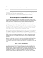
Installing AMC-101
Instructions given below detail the settings that you have to make in order to
configure AMC-101 for proper operation. The table, which comes after the
configuration instructions, lists the AMC-101 internal jumpers and their possible
settings.
Configuring AMC-101
To configure AMC-101:
1. Disconnect all the cables connected to AMC-101.
1. Unscrew the two rear panel screws holding the top panel.
2. Slide out the top panel to gain access to the interior of the unit.
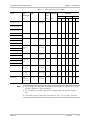
3. Set the JP2 and JP7 jumpers (see table below).
4. Reinstall the top cover.
Jumper
Description
Settings (Default settings in bold)
JP2
If illegal combination of card types and selected data
rate is detected, CONFIG alarm is relayed and FLT LED
blinks
Jumper installed
If illegal combination of card types and selected data
rate is detected, CONFIG alarm is masked and FLT LED
remains OFF
Jumper not installed
If no signal is received from the other side, idle signal is
transmitted
Jumper installed
If no signal is received from the other side, idle signal is
not transmitted
Jumper not installed
JP7
AMC-101
Installing AMC-101
1
Quick Start Guide
Installation and Operation Manual
Installing Interface Modules
The AMC-101 interface modules are hot-swappable, that means they can be
replaced when the unit is ON.
To install an interface module:
1. Slide the module into appropriate slot.
2. Fasten the two front panel screws to secure the module to the AMC-101
frame.
Connecting the Cables
To connect the fiber optic cables:
1. Remove the protective caps from the connectors and store them in a safe
place for later use.
2. Connect the transmit fiber to the connector marked TX and the receive fiber to
the connector marked RX.
3. At the remote unit connect the transmit fiber to RX and the receive fiber to TX.
To connect AC power to AMC-101:
1. Connect the power cable to the power connector on the AMC-101 rear panel.
2. Connect the power cable to the mains outlet.
The unit will be turned on automatically upon connection to the mains.
To connect DC power to AMC-101:
•
2.
Refer to DC power supply connection supplement.
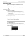
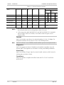
Operating AMC-101
AMC-101 requires no operator attention once installed, with the exception of
occasional monitoring of front panel indicators. Refer to table below for the correct
status of the AMC-101 indicators after the local and remote units are synchronized
and data is being transferred.
2
Operating AMC-101
Indicator
Status
PWR
ON
FLT (AMC-101)
OFF
WRAP
OFF
SIG
ON
AMC-101
Contents
Chapter 1. Introduction
1.1 Overview..................................................................................................................... 1-1
Applications.......................................................................................................................... 1-1
Features................................................................................................................................ 1-1
1.2 Physical Description..................................................................................................... 1-5
1.3 Functional Description................................................................................................. 1-6
1.4 Technical Specifications............................................................................................... 1-7
Chapter 2. Installation and Setup
2.1 Site Requirements and Prerequisites ............................................................................ 2-1
2.2 Package Contents ........................................................................................................ 2-1
2.3 Installing AMC-101 ...................................................................................................... 2-2
Configuring AMC-101...........................................................................................................2-2
Installing Interface Modules................................................................................................... 2-3
Connecting the Interfaces ..................................................................................................... 2-4
Connecting the Power .......................................................................................................... 2-4
Chapter 3. Operation
3.1 Front Panel Controls and Indicators ............................................................................. 3-1
3.2 Operating AMC-101 .................................................................................................... 3-2
Turning On AMC-101........................................................................................................... 3-2
Normal Indications ............................................................................................................... 3-2
Turning Off AMC-101........................................................................................................... 3-2
Chapter 4. Alarms and Diagnostics
4.1 Alarm Relay ................................................................................................................. 4-1
4.2 Diagnostic Loopbacks .................................................................................................. 4-2
Appendix A. Interface Modules
AMC-101
i
Table of Contents
ii
Installation and Operation Manual
AMC-101
Chapter 1
Introduction
1.1
Overview
AMC-101 is a universal modular media converter that provides retimed or
transparent conversion of optical and electrical signals for ATM, SDH/SONET,
FDDI, Fast Ethernet and other protocols at data rates of up to 155 Mbps.
The AMC-101 modules are also available as cards for LRS-101 broadband rack,
holding up to 14 cards.
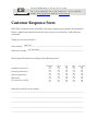
Applications
Figure 1-1 illustrates AMC-101 in an ATM extension application.
Central Office/POP
Customer Premises
Coaxial
Cable
Multimode Fiber
SDH/SONET
AMC-101
ATM Edge
Device
Coaxial
Cable
Multimode Fiber
AMC-101
ATM Device
Figure 1-1. AMC-101 Extending ATM Services over an SDH/SONET Network
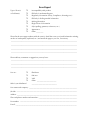
Figure 1-2 shows AMC-101 operating as a media converter and repeater.
Single Mode Fiber
Coaxial Cable
SDH/SONET
ADM
AMC-101
110 km (68 miles)
Single Mode Fiber
AMC-101
110 km (68 miles)
Multimode Fiber
AMC-101
2 km (1.2 miles)
ATM Device
Figure 1-2. AMC-101 Operating as Media Converter and Repeater
Features
AMC-101 is a modular media converter and repeater, operating over fiber optic,
UTP, STP and coax lines.
Retimed Media Conversion
AMC-101 supports retimed media converting/repeating for:
• 51 Mbps OC-1
• 100 Mbps TAXI
• 155 Mbps OC-3/STM-1
• 155 Mbps STS-3c over UTP/STP cables
• 155 Mbps STS-3c/STM-1 over coax cables
AMC-101
Overview
1-1
Chapter 1 Introduction
•
•
Installation and Operation Manual
FDDI
Fast Ethernet.
Retimed modules provide clock regeneration and data reshaping.
Transparent Media Conversion
AMC-101 supports transparent conversion of fiber optic signals up to 155 Mbps
for:
• ATM/SDH/SONET
• Ethernet
• Token Ring.
Transparent modules provide low-cost conversion for applications that do not
require repeating or reclocking. In addition, AMC-101 provides Ethernet bridging
over fiber optic links.
AMC-101 Modules
AMC-101 supports hot-swappable, electrical and fiber optic modules, including
long haul and WDM interfaces. Table 1-1 and Table 1-2 list all fiber optic and
electrical modules supported by AMC-101. Appendix A provides schematics of the
modules and their technical specifications.
1-2
Overview
AMC-101
Installation and Operation Manual
Chapter 1 Introduction
Table 1-1. Fiber Optic Interface Modules
Module
Name
Transmitter
Type,
Wavelength
Connector
Type
Fiber Type
[nm]
Typical
Optical
Power
Receiver
Sensitivity
Typical Range According to
Data Rates
[dBm]
[dBm]
[km] [miles] [km] [miles] [km] [miles]
51 Mbps
100 Mbps
155 Mbps
VCSEL, 850
SC, ST, FC
62.5/125,
multimode
-17
-30
3
1.8
2
1.2
2
1.2
LED, 1310
SC, ST
62.5/125,
multimode
-18
-31
4
2.4
2
1.2
2
1.2
Laser, 1310
SC, ST, FC
9/125,
single mode
-12
-31
40
25
25
15.5
20
12.4
Laser
(long haul),
1310
SC, ST, FC
9/125,
single mode
-2
-34
60
37
50
31
40
25
Laser, 1550
ST, FC
9/125,
single mode
-12
-31
50
31
25
15.5
20
12.4
Laser
(long haul),
1550
SC, ST, FC
9/125,
single mode
-2
-34
110
68
100
62.1
80
49.7
AMC-M/SF1/SC
Laser (WDM),
Tx – 1310
Rx – 1550
SC
9/125,
single mode
-12
-29
35
21.7
25
15.5
20
12.4
AMC-M/SF2/SC
Laser (WDM),
Tx – 1550
Rx – 1310
SC
9/125,
single mode
-12
-29
35
21.7
25
15.5
20
12.4
AMC-M/SF3
Laser
(single fiber),
1310 Tx and
Rx
SC/APC
9/125,
single mode
-12
-27
20
12.4
20
12.4
20
12.4
AMC-M/MM/ST/85
(transparent only)
AMC-M/MM/SC/85
(transparent only)
AMC-M/MM/FC/85
(transparent only)
AMC-M/MM/SC/13
AMC-M/MM/ST/13
AMC-M/SM/SC/13L
AMC-M/SM/ST/13L
AMC-M/SM/FC/13L
AMC-M/SM/SC/13LH
AMC-M/SM/ST/13LH
AMC-M/SM/FC/13LH
AMC-M/SM/ST/15L
AMC-M/SM/FC/15L
AMC-M/SM/SC/15LH
AMC-M/SM/ST/15LH
AMC-M/SM/FC/15LH
Note
• Typical ranges are calculated according to attenuation of 0.4 db/km for 1310 nm
and 0.25 dB/km for 1550 nm modules.
• The Fast Ethernet and FDDI protocols are supported by the retimed modules
only.
• All modules support TAXI, FDDI, Fast Ethernet, STS-1, STS-3c/STM-1 protocols.
AMC-101
Overview
1-3
Chapter 1 Introduction
Installation and Operation Manual
Table 1-2. Electrical Interface Modules
Module
Name
Retimed/
Transparent
Protocols
Supported
Cable
Type
Connector
Type
Impedance
Typical Range (Attenuation)
Retimed
Mode
Transparent
Mode
[Ω]
[m]
[ft]
[m]
[ft]
AMC-M/UTP/155
R/T
STS-3c
UTP Cat 5
Shielded RJ-45
100
100
328
50
164
AMC-M/STP/155
R/T
STS-3c
STP Type 1
DB-9
150
100
328
50
164
AMC-M/UTP/100
R/T
FDDI
UTP Cat 5
Shielded RJ-45
100
100
328
50
164
AMC-M/10BT/B*
R
Ethernet
UTP Cat 5
Shielded RJ-45
100
100
328
–
–
AMC-M/CX/BNC/155
R
STS-3c,
STM-1
Coax
BNC
75
12.7 dB**
AMC-M/CX/DIN/155
R
STS-3c,
STM-1
Coax
DIN 47295
1.6/5.6 coax
75
12.7 dB**
Notes
• The AMC-M/10BT/B modules require the modules of the same type installed at
the local and remote sites of the application (AMC-101 only).
• 135m range of the AMC-M/CX/BNC/155 and AMC-M/CX/DIN/155 is attainable
when using RG-59 B/U (at 78 MHz, in accordance with the square root of
frequency law).
Controls
AMC-101 includes a rate selector for retimed modules (51, 100, 155 Mbps). For
transparent modules, the rate selector is set to the OTHER position.
Note
If the rate selector is set to OTHER, retimed modules operate in transparent mode.
Diagnostics
AMC-101 supports activation of simultaneous loopbacks towards the user and
network sides. The loopbacks are activated via a front panel WRAP pushbutton.
Alarm Relay
AMC-101 includes a D-type 9-pin dry contact female connector, which serves for
relaying major and minor alarms.
Compliance
AMC-101 operation complies with ATM Forum and ITU-T G.957 and G.958
specifications.
1-4
Overview
AMC-101
Installation and Operation Manual
1.2
Chapter 1 Introduction
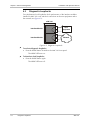
Physical Description
AMC-101 is a modular standalone unit intended for the desktop or 19-inch rack
installation. Figure 1-3 illustrates a 3D view of a typical AMC-101 unit.
Figure 1-3. AMC-101, 3D View
The front panel of the unit includes interface modules, LEDs, rate selector and
loopback activation pushbutton. For a detailed description of the front panel, see
Chapter 3.
The rear panel includes a power connector (AC or DC) and alarm relay port. The
AMC-101 rear panel is described in greater detail in Chapter 2.
AMC-101
Physical Description
1-5
Chapter 1 Introduction
1.3
Installation and Operation Manual
Functional Description
Figure 1-4 illustrates the AMC-101 circuit blocks in the form of the functional block
diagram.
PWR LED
Dry Contact
FLT LED
Relay 1
WRAP LED
Control
Logic
WRAP Pushbutton
Relay 2
Relay 3
51
100
RATE
Rotary Switch 155
OTHER
Mux
Control
Mux
Idle
AMC-101 Module
Fiber/Copper
Transmitter
Data
REF Clock
Fiber/Copper
Receiver
Retiming
Mux
Control
Data
Status
SIG LED
Mux
AMC-101 Module
Module Connectors
Idle
Fiber/Copper
Transmitter
Data
Fiber/Copper
Receiver
REF Clock
Retiming
Data
Status
SIG LED
Frequency
Sources
Reference Frequency
MUX
Figure 1-4. AMC-101Block Diagram
1-6
Functional Description
AMC-101
Installation and Operation Manual
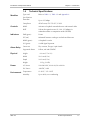
1.4
Modules
Controls
Indicators
Alarm Relay
Physical
Technical Specifications
Types and
Specifications
Refer to Table 1-1, Table 1-2 and Appendix A
Data Rate
Up to 155 Mbps
Compliance
ATM Forum, ITU-T G.957, G.958
WRAP
Activates a loopback towards the user and network sides
RATE
Selects the operation rate (51, 100, 155 Mbps) for
retimed modules or transparent mode (OTHER)
PWR (green)
Power
FLT (red)
Mismatch between card type and selected data rate
WRAP (green)
A loopback is active
SIG (green)
A valid signal is present
Connector
Dry contacts, D-type, 9-pin female
Supported Alarms
Yellow, red and CONFIG
Height
21.6 cm (8.5 in)
Depth
24.2 cm (9.5 in)
1.1 kg (2.4 lb)
AC Source
100–240 VAC, 0.8–0.4A, 50 or 60 Hz
DC Source
-48 VDC, 16W
Environment Temperature
Humidity
AMC-101
4.4 cm (1.7 in 1U)
Width
Weight
Power
Chapter 1 Introduction
0°–50°C / 32°–122°F
Up to 90%, non–condensing
Technical Specifications
1-7
Chapter 1 Introduction
1-8
Technical Specifications
Installation and Operation Manual
AMC-101
Chapter 2
Installation and Setup
This chapter describes installation and setup procedures for the AMC-101 unit.
AMC-101 is delivered completely assembled. It is designed for tabletop or 19-inch
rack installation. For instructions on installation of a single unit or two units in a
19-inch rack, refer to the rack mounting kit for 19-inch racks guide that comes
with the RM kit.
After installing the unit, refer to Chapter 3 to assure normal operation.
In case a problem encountered, refer to Chapter 4 for test and diagnostic instructions.
Internal settings, adjustment, maintenance, and repairs may be performed
only by a skilled technician who is aware of the hazards involved.
Always observe standard safety precautions during installation, operation, and
Warning maintenance of this product.
2.1
Site Requirements and Prerequisites
An AC-powered AMC-101 should be installed within 1.5m (5 ft) of an easily
accessible grounded AC outlet. The outlet should furnish 100–230 VAC current.
A DC-powered AMC-101 unit requires -48 VDC power source, which must be
adequately isolated from the mains supply. In order to prevent a fire hazard, a
suitable fuse should be installed in the DC line.
Allow at least 90 cm (36 in) of frontal clearance for operating and maintenance
accessibility. Allow at least 10 cm (4 in) clearance at the rear of the unit for signal
lines and interface cables.
The ambient operating temperature of AMC-101 is 0 to 50°C (32 to 122°F) at
relative humidity of 90%, non-condensing.
2.2
Package Contents
The AMC-101 package includes the following items:
• One AMC-101 unit
• Interface card(s)
• Technical documentation CD
• AC power cord or DC power supply connector kit
• RM-101 rack mount kit (if ordered).
AMC-101
Package Contents
2-1
Chapter 2 Installation and Setup
2.3
Installation and Operation Manual
Installing AMC-101
AMC-101 is a standalone device intended for tabletop or bench installation. It is
delivered completely assembled. No provision is made for bolting the unit on the
tabletop.
To install AMC-101:
1. Determine the required configuration of AMC-101 and set the internal
jumpers and switches accordingly (see Configuring AMC-101 below).
2. Install interface modules (see Installing Interface Modules below).
3. Connect the interfaces (see Connecting the Interfaces below).
4. Connect power to the unit (see Connecting the Power below).
Warning
Access to the inside of the equipment is permitted only to the authorized and
qualified personnel.
To avoid accidental electric shock, always disconnect the interface cables and
the power cord before removing the unit from its casing.
Line voltages are present inside AMC-101 when it is connected to power
and/or the lines. Moreover, under certain fault conditions, dangerous voltages
may appear on the lines connected to the unit.
Any adjustment, maintenance and repair of the opened instrument under
voltage must be avoided as much as possible and, when inevitable, should be
carried out only by a skilled technician who is aware of the hazard involved.
Capacitors inside the unit may still be charged even after the unit has been
disconnected from its source of power.
Caution AMC-101 contains components sensitive to electrostatic discharge (ESD). To
prevent ESD damage, avoid touching the internal components. Before moving
jumpers, touch the AMC-101 rear panel.
Configuring AMC-101
This section describes how to set two jumpers located on the AMC-101 printedcircuit board. Figure 2-1 illustrates the layout of the AMC-101 PCB. Table 2-1
provides details on the functions of the internal jumpers and their default settings.
To set the internal jumpers:
5. Disconnect all the cables connected to AMC-101.
6. Unscrew the two rear panel screws holding the top panel.
7. Slide out the top panel to gain access to the interior of the unit.
8. Set the JP2 and JP7 jumpers (see Figure 2-1 and Table 2-1).
9. Reinstall the top cover.
Caution The AMC-101 PCB contains additional jumpers and switches that are factory-set
and must not be moved by the user.
2-2
Installing AMC-101
AMC-101
Installation and Operation Manual
Chapter 2 Installation and Setup
Alarm Relay
Connector
Alarm Relay
Card
JP2
AC
Power Supply
GND
VCC
IDLE_EN
JP7
Interface
Module
Interface
Module
LEDs Card
Figure 2-1. PCB Layout
Table 2-1. Jumper Settings
Jumper
Description
Settings (Default settings in bold)
JP2
If illegal combination of card types and selected data
rate is detected, CONFIG alarm is relayed and FLT LED
blinks
Jumper installed
If illegal combination of card types and selected data
rate is detected, CONFIG alarm is masked and FLT LED
remains OFF
Jumper not installed
If no signal is received from the other side, idle signal is
transmitted
Jumper installed
If no signal is received from the other side, idle signal is
not transmitted
Jumper not installed
JP7
Installing Interface Modules
AMC-101 interface modules are hot-swappable, that means they can be replaced
when the unit is ON.
To install an interface module:
1. Slide the module into appropriate slot.
2. Fasten the two front panel screws to secure the module to the AMC-101
frame.
AMC-101
Installing AMC-101
2-3
Chapter 2 Installation and Setup
Installation and Operation Manual
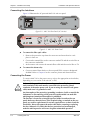
Connecting the Interfaces
Figure 2-2 illustrates the AC-powered AMC-101 unit rear panel.
ALARMS
Figure 2-2. AMC-101 Rear Panel (AC Version)
OTHER
155
100
51
PWR FLT
WRAP
RATE
AMC-T
SIG
ST/MM
AMC-T
TX
RX
SIG
850
ST/SM
TX
RX
1300
Figure 2-3. AMC-101 Front Panel
To connect the fiber optic cables:
1. Remove the protective caps from the connectors and store them in a safe
place for later use.
2. Connect the transmit fiber to the connector marked TX and the receive fiber to
the connector marked RX.
3. At the remote unit connect the transmit fiber to RX and the receive fiber to TX.
To connect the alarm relay:
• Connect external alarm device to the rear panel DB-9 connector designated
ALARMS. Refer to Chapter 4 for the connector pinout and alarm functions.
Connecting the Power
To connect AMC-101 to the power source, refer to the appropriate section below,
depending on your version of the unit (AC or DC).
Warning
2-4
Before switching on this unit and connecting any other cable, the protective
earth terminals of this unit must be connected to the protective ground
conductor of the mains power cord. If you are using an extension cord (power
cable) make sure it is grounded as well.
Any interruption of the protective (grounding) conductor (inside or outside the
instrument) or disconnecting of the protective earth terminal can make this
unit dangerous. Intentional interruption is prohibited.
The line fuse is located in an integral-type fuse holder located on the rear
panel. Make sure that only fuses of the required rating, as marked on the rear
panel, are used for replacement. Do not use repaired fuses or short-circuit the
fuse holder. Always disconnect the mains cable before removing or replacing
the fuse. Whenever it is likely that the fuse protection has been damaged,
make the unit inoperative and secure it against unintended operation.
Installing AMC-101
AMC-101
Installation and Operation Manual
Chapter 2 Installation and Setup
AC Power Connection
AC power should be supplied to AMC-101 through the 1.5m (5 ft) standard power
cable terminated by a standard 3-prong plug. The cable is provided with the unit.
To connect AC power:
1. Connect the power cable to the power connector on the AMC-101 rear panel.
2. Connect the power cable to the mains outlet.
The unit turns on automatically upon connection to the mains.
DC Power Connection
To connect DC power:
•
AMC-101
Refer to DC power supply connection supplement.
Installing AMC-101
2-5
Chapter 2 Installation and Setup
2-6
Installing AMC-101
Installation and Operation Manual
AMC-101
Chapter 3
Operation
This chapter provides the following information for the AMC-101 unit:
•
•
AMC-101 front-panel indicators and controls
Operating procedures (turn-on, front-panel indications, performance
monitoring and turn-off).
Installation procedures given in Chapter 2 must be completed and checked before
attempting to operate AMC-101.
3.1
Front Panel Controls and Indicators
Figure 3-1 shows the AMC-101 front panel. Table 3-1 lists the AMC-101 controls
and indicators.
OTHER
155
100
51
PWR FLT
WRAP
RATE
AMC-T
SIG
AMC-T
TX
RX
ST/MM
SIG
850
TX
RX
ST/SM
1300
Figure 3-1. AMC-101 Front Panel
Table 3-1. AMC-101 Front Panel Controls and Indicators
Name
Type
Function
PWR
Green LED
ON – Power is ON
FLT
Red LED
Blinks – Illegal combination of card types and selected data rate is
detected
WRAP
Green LED
ON – A loopback is running towards the user and network sides
SIG
Green LED
ON – A valid signal is received
OFF – No signal is detected
Blinks – Internal PLL is unlocked (retimed modules only)
WRAP
Pushbutton
Activates simultaneous loopbacks toward user and network sides
RATE
Rotary switch
Selects the operation rate (51, 100, 155 Mbps) for retimed
modules or transparent mode (OTHER)
Note: If the rate selector is set to OTHER, retimed modules operate in transparent mode.
AMC-101
Front Panel Controls and Indicators
3-1
Chapter 3 Operation
3.2
Installation and Operation Manual
Operating AMC-101
Turning On AMC-101
AMC-101 is turned on as soon as power is connected. When power is connected,
the PWR indicator lights up and remains lit as long as AMC-101 receives power.
AMC-101 requires no operator attention once installed, with the exception of
occasional monitoring of front panel indicators. Intervention is only required when
the unit must be configured to new operational requirements, or the diagnostic
tests must be performed.
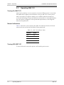
Normal Indications
Table 3-2 shows the correct status of the AMC-101 indicators after the local and
remote units are synchronized and data is being transferred.
Table 3-2. AMC-101 Indicator Status
Indicator
Status
PWR
ON
FLT
OFF
WRAP
OFF
SIG
ON
Turning Off AMC-101
To turn off the unit, remove the power cord from the power source.
3-2
Operating AMC-101
AMC-101
Chapter 4
Alarms and Diagnostics
4.1
Alarm Relay
The rear panel of AMC-101 units includes a D-type 9-pin female connector
designated ALARMS. Figure 4-1 illustrates the pinout of the AMC-101 alarm relay
connector.
5 4 3 2 1
9 8 7 6
Figure 4-1. Alarm Relay Connector Pinout
The ALARMS connector is used to relay the following alarms:
•
RED – Power Failure (DC voltage on board)
•
YELLOW – Signal Detect Failure (to any of the unit modules)
•
CONFIG – Improper Configuration (incompatible modules and/or data rates
selected).
Three pins are dedicated for each alarm: Common (COM), OK and FAIL. The
COM pin is the input for each alarm. The user can drive the COM pin with any
signal (0 to 5V). If the signal is received OK, the COM pin is connected to its
corresponding OK pin. If there is a failure, the COM pin is connected to its
corresponding FAIL pin. See Table 4-1 for the connector pin assignments.
For example, for the RED alarm the common input (COM) pin is 9. If there is no
power failure, it connects to pin 4 (OK). If there is a failure, pin 9 connects to pin 5
(FAIL).
Table 4-1. Alarm Relay Connector Pin Assignment
Note
AMC-101
Alarm
COM
OK
FAIL
RED
9
4
5
YELLOW
3
8
7
CONFIG
6
2
1
You can prevent AMC-101 from relaying CONFIG alarm by removing the JP2
jumper plug, as explained in Configuring AMC-101 in Chapter 2.
Alarm Relay
4-1
Chapter 4 Alarms and Diagnostics
4.2
Installation and Operation Manual
Diagnostic Loopbacks
Two simultaneous local loopbacks check performance of the interface modules
installed in AMC-101 card, and their connections to the user equipment and to
the network (see Figure 4-2).
AMC-101
Tx
Interface Module
Rx
User
Equipment
Tx
Interface Module
Rx
Network
Figure 4-2. Diagnostic Loopbacks
To activate diagnostic loopbacks:
•
Press the WRAP button located on the AMC-101 front panel.
The WRAP LED turns on.
To deactivate local loopbacks:
•
Press the WRAP button again.
The WRAP LED turns off.
4-2
Diagnostic Loopbacks
AMC-101
Appendix A
Interface Modules
This appendix describes modules supported by the AMC-101 converter, providing
schematics of the front panel and technical specifications.
A.1
Fiber Optic Modules
Typical ranges are calculated according to attenuation of 0.4 db/km for 1310 nm
and 0.25 db/km for 1550 nm modules.
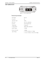
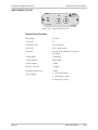
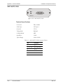
AMC-M/MM/ST/85/T
AMC-T
TX
RX
LASER
CLASS
1
SIG
ST/ MM
850
Figure A-1. AMC-M/MM/ST/85/T
Technical Specifications
Wavelength
850 nm
Connector
ST
Transmitter Type
VCSEL
Fiber Type
62.5/125, multimode
Protocols
Token Ring, Ethernet
Timing Mode
Transparent
Coding Method
4B/5B, NRZ, Manchester
Optical Output
-18 dBm
Receiver Sensitivity
-30 dBm
Typical Range
• 3 km (1.8 miles) for 51 Mbps
• 2 km (1.2 miles) for 100 and 155 Mbps
AMC-101
Fiber Optic Modules
A-1
Appendix A Interface Modules
Installation and Operation Manual
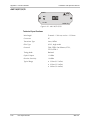
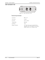
AMC-M/MM/SC/85/T
AMC-T
TX
RX
LASER
CLASS
1
SIG
SC/ MM
850
Figure A-2. AMC-M/MM/ST/85/T
Technical Specifications
Wavelength
850 nm
Connector
SC
Transmitter Type
VCSEL
Fiber Type
62.5/125, multimode
Protocols
Token Ring, Ethernet
Timing Mode
Transparent
Coding Method
4B/5B, NRZ, Manchester
Optical Output
-18 dBm
Receiver Sensitivity
-30 dBm
Typical Range
• 3 km (1.8 miles) for 51 Mbps
• 2 km (1.2 miles) for 100 and 155 Mbps
A-2
Fiber Optic Modules
AMC-101
Installation and Operation Manual
Appendix A Interface Modules
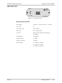
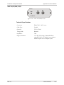
AMC-M/MM/FC/85/T
AMC-T
TX
RX
LASER
CLASS
1
SIG
FC/ MM
850
Figure A-3. AMC-M/MM/ST/85/T
Technical Specifications
Wavelength
850 nm
Connector
SC
Transmitter Type
VCSEL
Fiber Type
62.5/125, multimode
Protocols
Token Ring, Ethernet
Timing Mode
Transparent
Coding Method
4B/5B, NRZ, Manchester
Optical Output
-18 dBm
Receiver Sensitivity
-30 dBm
Typical Range
• 3 km (1.8 miles) for 51 Mbps
• 2 km (1.2 miles) for 100 and 155 Mbps
AMC-101
Fiber Optic Modules
A-3
Appendix A Interface Modules
Installation and Operation Manual
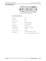
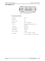
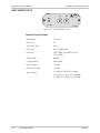
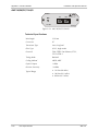
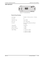
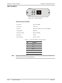
AMC-M/MM/SC/13/R
AMC-R
TX
RX
SIG
SC/ MM
1300
Figure A-4. AMC-M/MM/SC/13/R
Technical Specifications
Wavelength
1310 nm
Connector
SC
Transmitter Type
LED
Fiber Type
62.5/125, multimode
Protocols
TAXI, FDDI, Fast Ethernet, STS-1,
STS-3c/STM-1
Timing Mode
Retimed
Coding Method
4B/5B, NRZ
Optical Output
-18 dBm
Receiver Sensitivity
-31 dBm
Typical Range
• 4 km (2.4 miles) for 51 Mbps
• 2 km (1.2 miles) for 100 and 155 Mbps
A-4
Fiber Optic Modules
AMC-101
Installation and Operation Manual
Appendix A Interface Modules
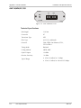
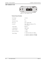
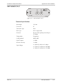
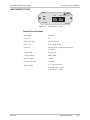
AMC-M/MM/SC/13/T
AMC-T
TX
RX
SIG
SC/ MM
1300
Figure A-5. AMC-M/MM/SC/13/T
Technical Specifications
Wavelength
1310 nm
Connector
SC
Transmitter Type
LED
Fiber Type
62.5/125, multimode
Protocols
Any two level optical protocols up to
155 Mbps
Timing Mode
Transparent
Coding Method
4B/5B, NRZ
Optical Output
-18 dBm
Receiver Sensitivity
-31 dBm
Typical Range
• 4 km (2.4 miles) for 51 Mbps
• 2 km (1.2 miles) for 100 and 155 Mbps
AMC-101
Fiber Optic Modules
A-5
Appendix A Interface Modules
Installation and Operation Manual
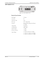
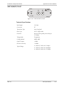
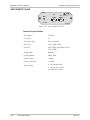
AMC-M/MM/ST/13/R
AMC-R
TX
RX
SIG
ST/ MM
1300
Figure A-6. AMC-M/MM/ST/13/R
Technical Specifications
Wavelength
1310 nm
Connector
ST
Transmitter Type
LED
Fiber Type
62.5/125, multimode
Protocols
TAXI, FDDI, Fast Ethernet, STS-1,
STS-3c/STM-1
Timing Mode
Retimed
Coding Method
4B/5B, NRZ
Optical Output
-18 dBm
Receiver Sensitivity
-31 dBm
Typical Range
• 4 km (2.4 miles) for 51 Mbps
• 2 km (1.2 miles) for 100 and 155 Mbps
A-6
Fiber Optic Modules
AMC-101
Installation and Operation Manual
Appendix A Interface Modules
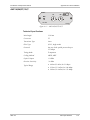
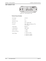
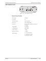
AMC-M/MM/ST/13/T
AMC-T
TX
RX
SIG
ST/ MM
1300
Figure A-7. AMC-M/MM/ST/13/T
Technical Specifications
Wavelength
1310 nm
Connector
ST
Transmitter Type
LED
Fiber Type
62.5/125, multimode
Protocols
Any two level optical protocols up to
155 Mbps
Timing Mode
Transparent
Coding Method
4B/5B, NRZ
Optical Output
-18 dBm
Receiver Sensitivity
-31 dBm
Typical Range
• 4 km (2.4 miles) for 51 Mbps
• 2 km (1.2 miles) for 100 and 155 Mbps
AMC-101
Fiber Optic Modules
A-7
Appendix A Interface Modules
Installation and Operation Manual
AMC-M/SM/SC/13L/R
AMC-R
TX
RX
LASER
CLASS
1
SIG
SC/ SM
1300L
Figure A-8. AMC-M/SM/SC/13L/R
Technical Specifications
Wavelength
1310 nm
Connector
SC
Transmitter Type
Laser
Fiber Type
9/125, single mode
Protocols
TAXI, FDDI, Fast Ethernet, STS-1,
STS-3c/STM-1
Timing Mode
Retimed
Coding Method
4B/5B, NRZ
Optical Output
-12 dBm
Receiver Sensitivity
-31 dBm
Typical Range
• 40 km (25 miles) for 51 Mbps
• 25 km (15.5 miles) for 100 Mbps
• 20 km (12.4 miles) for 155 Mbps
A-8
Fiber Optic Modules
AMC-101
Installation and Operation Manual
Appendix A Interface Modules
AMC-M/SM/SC/13L/T
AMC-T
TX
RX
LASER
CLASS
1
SIG
SC/ SM
1300L
Figure A-9. AMC-M/SM/SC/13L/T
Technical Specifications
Wavelength
1310 nm
Connector
SC
Transmitter Type
Laser
Fiber Type
9/125, single mode
Protocols
Any two level optical protocols up to
155 Mbps
Timing Mode
Transparent
Coding Method
4B/5B, NRZ
Optical Output
-12 dBm
Receiver Sensitivity
-31 dBm
Typical Range
• 40 km (25 miles) for 51 Mbps
• 25 km (15.5 miles) for 100 Mbps
• 20 km (12.4 miles) for 155 Mbps
AMC-101
Fiber Optic Modules
A-9
Appendix A Interface Modules
Installation and Operation Manual
AMC-M/SM/ST/13L/R
AMC-R
TX
RX
LASER
CLASS
1
SIG
ST/ SM
1300L
Figure A-10. AMC-M/SM/ST/13L/R
Technical Specifications
Wavelength
1310 nm
Connector
ST
Transmitter Type
Laser
Fiber Type
9/125, single mode
Protocols
TAXI, FDDI, Fast Ethernet, STS-1,
STS-3c/STM-1
Timing Mode
Retimed
Coding Method
4B/5B, NRZ
Optical Output
-12 dBm
Receiver Sensitivity
-31 dBm
Typical Range
• 40 km (25 miles) for 51 Mbps
• 25 km (15.5 miles) for 100 Mbps
• 20 km (12.4 miles) for 155 Mbps
A-10
Fiber Optic Modules
AMC-101
Installation and Operation Manual
Appendix A Interface Modules
AMC-M/SM/ST/13L/T
AMC-T
TX
RX
LASER
CLASS
1
SIG
ST/ SM
1300L
Figure A-11. AMC-M/SM/ST/13L/T
Technical Specifications
Wavelength
1310 nm
Connector
ST
Transmitter Type
Laser
Fiber Type
9/125, single mode
Protocols
Any two level optical protocols up to
155 Mbps
Timing Mode
Transparent
Coding Method
4B/5B, NRZ
Optical Output
-12 dBm
Receiver Sensitivity
-31 dBm
Typical Range
• 40 km (25 miles) for 51 Mbps
• 25 km (15.5 miles) for 100 Mbps
• 20 km (12.4 miles) for 155 Mbps
AMC-101
Fiber Optic Modules
A-11
Appendix A Interface Modules
Installation and Operation Manual
AMC-M/SM/FC/13L/R
AMC-R
TX
RX
LASER
CLASS
1
SIG
FC/ SM
1300L
Figure A-12. AMC-M/SM/FC/13L/R
Technical Specifications
Wavelength
1310 nm
Connector
FC
Transmitter Type
Laser
Fiber Type
9/125, single mode
Protocols
TAXI, FDDI, Fast Ethernet, STS-1,
STS-3c/STM-1
Timing Mode
Retimed
Coding Method
4B/5B, NRZ
Optical Output
-12 dBm
Receiver Sensitivity
-31 dBm
Typical Range
• 40 km (25 miles) for 51 Mbps
• 25 km (15.5 miles) for 100 Mbps
• 20 km (12.4 miles) for 155 Mbps
A-12
Fiber Optic Modules
AMC-101
Installation and Operation Manual
Appendix A Interface Modules
AMC-M/SM/FC/13L/T
AMC-T
TX
RX
LASER
CLASS
1
SIG
FC/ SM
1300L
Figure A-13. AMC-M/SM/FC/13L/T
Technical Specifications
Wavelength
1310 nm
Connector
FC
Transmitter Type
Laser
Fiber Type
9/125, single mode
Protocols
Any two level optical protocols up to
155 Mbps
Timing Mode
Transparent
Coding Method
4B/5B, NRZ
Optical Output
-12 dBm
Receiver Sensitivity
-31 dBm
Typical Range
• 40 km (25 miles) for 51 Mbps
• 25 km (15.5 miles) for 100 Mbps
• 20 km (12.4 miles) for 155 Mbps
AMC-101
Fiber Optic Modules
A-13
Appendix A Interface Modules
Installation and Operation Manual
AMC-M/SM/SC/13LH/R
AMC-R
TX
RX
LASER
CLASS
1
SIG
SC/ SM
1300LH
Figure A-14. AMC-M/SM/SC/13LH/R
Technical Specifications
Wavelength
1310 nm
Connector
SC
Transmitter Type
Laser, long haul
Fiber Type
9/125, single mode
Protocols
TAXI, FDDI, Fast Ethernet, STS-1,
STS-3c/STM-1
Timing Mode
Retimed
Coding Method
4B/5B, NRZ
Optical Output
-2 dBm
Receiver Sensitivity
-34 dBm
Typical Range
• 60 km (37 miles) for 51 Mbps
• 50 km (31 miles) for 100 Mbps
• 40 km (25 miles) for 155 Mbps
A-14
Fiber Optic Modules
AMC-101
Installation and Operation Manual
Appendix A Interface Modules
AMC-M/SM/SC/13LH/T
AMC-T
TX
RX
LASER
CLASS
1
SIG
SC/ SM
1300LH
Figure A-15. AMC-M/SM/SC/13LH/T
Technical Specifications
Wavelength
1310 nm
Connector
SC
Transmitter Type
Laser, long haul
Fiber Type
9/125, single mode
Protocols
Any two level optical protocols up to
155 Mbps
Timing Mode
Transparent
Coding Method
4B/5B, NRZ
Optical Output
-2 dBm
Receiver Sensitivity
-34 dBm
Typical Range
• 60 km (37 miles) for 51 Mbps
• 50 km (31 miles) for 100 Mbps
• 40 km (25 miles) for 155 Mbps
AMC-101
Fiber Optic Modules
A-15
Appendix A Interface Modules
Installation and Operation Manual
AMC-M/SM/ST/13LH/R
AMC-R
TX
RX
LASER
CLASS
1
SIG
ST/ SM
1300LH
Figure A-16. AMC-M/SM/ST/13LH/R
Technical Specifications
Wavelength
1310 nm
Connector
ST
Transmitter Type
Laser, long haul
Fiber Type
9/125, single mode
Protocols
TAXI, FDDI, Fast Ethernet, STS-1,
STS-3c/STM-1
Timing Mode
Retimed
Coding Method
4B/5B, NRZ
Optical Output
-2 dBm
Receiver Sensitivity
-34 dBm
Typical Range
• 60 km (37 miles) for 51 Mbps
• 50 km (31 miles) for 100 Mbps
• 40 km (25 miles) for 155 Mbps
A-16
Fiber Optic Modules
AMC-101
Installation and Operation Manual
Appendix A Interface Modules
AMC-M/SM/ST/13LH/T
AMC-T
TX
RX
LASER
CLASS
1
SIG
ST/ SM
1300LH
Figure A-17. AMC-M/SM/ST/13LH/T
Technical Specifications
Wavelength
1310 nm
Connector
ST
Transmitter Type
Laser, long haul
Fiber Type
9/125, single mode
Protocols
Any two level optical protocols up to
155 Mbps
Timing Mode
Transparent
Coding Method
4B/5B, NRZ
Optical Output
-2 dBm
Receiver Sensitivity
-34 dBm
Typical Range
• 60 km (37 miles) for 51 Mbps
• 50 km (31 miles) for 100 Mbps
• 40 km (25 miles) for 155 Mbps
AMC-101
Fiber Optic Modules
A-17
Appendix A Interface Modules
Installation and Operation Manual
AMC-M/SM/FC/13LH/R
AMC-R
TX
RX
LASER
CLASS
1
SIG
FC/ SM
1300LH
Figure A-18. AMC-M/SM/FC/13LH/R
Technical Specifications
Wavelength
1310 nm
Connector
FC
Transmitter Type
Laser, long haul
Fiber Type
9/125, single mode
Protocols
TAXI, FDDI, Fast Ethernet, STS-1,
STS-3c/STM-1
Timing Mode
Retimed
Coding Method
4B/5B, NRZ
Optical Output
-2 dBm
Receiver Sensitivity
-34 dBm
Typical Range
• 60 km (37 miles) for 51 Mbps
• 50 km (31 miles) for 100 Mbps
• 40 km (25 miles) for 155 Mbps
A-18
Fiber Optic Modules
AMC-101
Installation and Operation Manual
Appendix A Interface Modules
AMC-M/SM/FC/13LH/T
AMC-T
TX
RX
LASER
CLASS
1
SIG
FC/ SM
1300LH
Figure A-19. AMC-M/SM/FC/13LH/T
Technical Specifications
Wavelength
1310 nm
Connector
FC
Transmitter Type
Laser, long haul
Fiber Type
9/125, single mode
Protocols
Any two level optical protocols up to
155 Mbps
Timing Mode
Transparent
Coding Method
4B/5B, NRZ
Optical Output
-2 dBm
Receiver Sensitivity
-34 dBm
Typical Range
• 60 km (37 miles) for 51 Mbps
• 50 km (31 miles) for 100 Mbps
• 40 km (25 miles) for 155 Mbps
AMC-101
Fiber Optic Modules
A-19
Appendix A Interface Modules
Installation and Operation Manual
AMC-M/SM/ST/15L/R
AMC-R
TX
RX
LASER
CLASS
1
SIG
ST/ SM
1550L
Figure A-20. AMC-M/SM/ST/15L/R
Technical Specifications
Wavelength
1550 nm
Connector
ST
Transmitter Type
Laser
Fiber Type
9/125, single mode
Protocols
TAXI, FDDI, Fast Ethernet, STS-1,
STS-3c/STM-1
Timing Mode
Retimed
Coding Method
4B/5B, NRZ
Optical Output
-12 dBm
Receiver Sensitivity
-31 dBm
Typical Range
• 50 km (31 miles)
• 25 km (15.5 miles)
• 20 km (12.4 miles)
A-20
Fiber Optic Modules
AMC-101
Installation and Operation Manual
Appendix A Interface Modules
AMC-M/SM/ST/15L/T
AMC-T
TX
RX
LASER
CLASS
1
SIG
ST/ SM
1550L
Figure A-21. AMC-M/SM/ST/15L/T
Technical Specifications
Wavelength
1550 nm
Connector
ST
Transmitter Type
Laser
Fiber Type
9/125, single mode
Protocols
Any two level optical protocols up to
155 Mbps
Timing Mode
Transparent
Coding Method
4B/5B, NRZ
Optical Output
-12 dBm
Receiver Sensitivity
-31 dBm
Typical Range
• 50 km (31 miles)
• 25 km (15.5 miles)
• 20 km (12.4 miles)
AMC-101
Fiber Optic Modules
A-21
Appendix A Interface Modules
Installation and Operation Manual
AMC-M/SM/FC/15L/R
AMC-R
TX
RX
LASER
CLASS
1
SIG
FC/ SM
1550L
Figure A-22. AMC-M/SM/FC/15L/R
Technical Specifications
Wavelength
1550 nm
Connector
FC
Transmitter Type
Laser
Fiber Type
9/125, single mode
Protocols
TAXI, FDDI, Fast Ethernet, STS-1,
STS-3c/STM-1
Timing Mode
Retimed
Coding Method
4B/5B, NRZ
Optical Output
-12 dBm
Receiver Sensitivity
-31 dBm
Typical Range
• 50 km (31 miles)
• 25 km (15.5 miles)
• 20 km (12.4 miles)
A-22
Fiber Optic Modules
AMC-101
Installation and Operation Manual
Appendix A Interface Modules
AMC-M/SM/FC/15L/T
AMC-T
TX
RX
LASER
CLASS
1
SIG
FC/ SM
1550L
Figure A-23. AMC-M/SM/FC/15L/T
Technical Specifications
Wavelength
1550 nm
Connector
FC
Transmitter Type
Laser
Fiber Type
9/125, single mode
Protocols
Any two level optical protocols up to
155 Mbps
Timing Mode
Transparent
Coding Method
4B/5B, NRZ
Optical Output
-12 dBm
Receiver Sensitivity
-31 dBm
Typical Range
• 50 km (31 miles)
• 25 km (15.5 miles)
• 20 km (12.4 miles)
AMC-101
Fiber Optic Modules
A-23
Appendix A Interface Modules
Installation and Operation Manual
AMC-M/SM/SC/15LH/R
AMC-R
TX
SIG
RX
SC/ SM
LASER
CLASS
1
1550LH
Figure A-24. AMC-M/SM/SC/15LH/R
Technical Specifications
Wavelength
1550 nm
Connector
SC
Transmitter Type
Laser, long haul
Fiber Type
9/125, single mode
Protocols
TAXI, FDDI, Fast Ethernet, STS-1,
STS-3c/STM-1
Timing Mode
Retimed
Coding Method
4B/5B, NRZ
Optical Output
-2 dBm
Receiver Sensitivity
-34 dBm
Typical Range
• 110 km (68 miles)
• 100 km (62.1 miles)
• 80 km (49.7 miles)
A-24
Fiber Optic Modules
AMC-101
Installation and Operation Manual
Appendix A Interface Modules
AMC-M/SM/SC/15LH/T
AMC-T
TX
SIG
RX
SC/ SM
LASER
CLASS
1
1550LH
Figure A-25. AMC-M/SM/SC/15LH/T
Technical Specifications
Wavelength
1550 nm
Connector
SC
Transmitter Type
Laser, long haul
Fiber Type
9/125, single mode
Protocols
Any two level optical protocols up to
155 Mbps
Timing Mode
Transparent
Coding Method
4B/5B, NRZ
Optical Output
-2 dBm
Receiver Sensitivity
-34 dBm
Typical Range
• 110 km (68 miles)
• 100 km (62.1 miles)
• 80 km (49.7 miles)
AMC-101
Fiber Optic Modules
A-25
Appendix A Interface Modules
Installation and Operation Manual
AMC-M/SM/ST/15LH/R
AMC-R
TX
SIG
RX
ST/ SM
LASER
CLASS
1
1550LH
Figure A-26. AMC-M/SM/ST/15LH/R
Technical Specifications
Wavelength
1550 nm
Connector
ST
Transmitter Type
Laser, long haul
Fiber Type
9/125, single mode
Protocols
TAXI, FDDI, Fast Ethernet, STS-1,
STS-3c/STM-1
Timing Mode
Retimed
Coding Method
4B/5B, NRZ
Optical Output
-2 dBm
Receiver Sensitivity
-34 dBm
Typical Range
• 110 km (68 miles)
• 100 km (62.1 miles)
• 80 km (49.7 miles)
A-26
Fiber Optic Modules
AMC-101
Installation and Operation Manual
Appendix A Interface Modules
AMC-M/SM/ST/15LH/T
AMC-T
TX
SIG
RX
ST/ SM
LASER
CLASS
1
1550LH
Figure A-27. AMC-M/SM/ST/15LH/T
Technical Specifications
Wavelength
1550 nm
Connector
ST
Transmitter Type
Laser, long haul
Fiber Type
9/125, single mode
Protocols
Any two level optical protocols up to
155 Mbps
Timing Mode
Transparent
Coding Method
4B/5B, NRZ
Optical Output
-2 dBm
Receiver Sensitivity
-34 dBm
Typical Range
• 110 km (68 miles)
• 100 km (62.1 miles)
• 80 km (49.7 miles)
AMC-101
Fiber Optic Modules
A-27
Appendix A Interface Modules
Installation and Operation Manual
AMC-M/SM/FC/15LH/R
AMC-R
TX
SIG
RX
FC/ SM
LASER
CLASS
1
1550LH
Figure A-28. AMC-M/SM/FC/15LH/R
Technical Specifications
Wavelength
1550 nm
Connector
FC
Transmitter Type
Laser, long haul
Fiber Type
9/125, single mode
Protocols
TAXI, FDDI, Fast Ethernet, STS-1,
STS-3c/STM-1
Timing Mode
Retimed
Coding Method
4B/5B, NRZ
Optical Output
-2 dBm
Receiver Sensitivity
-34 dBm
Typical Range
• 110 km (68 miles)
• 100 km (62.1 miles)
• 80 km (49.7 miles)
A-28
Fiber Optic Modules
AMC-101
Installation and Operation Manual
Appendix A Interface Modules
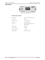
AMC-M/SM/FC/15LH/T
AMC-T
TX
SIG
RX
FC/ SM
LASER
CLASS
1
1550LH
Figure A-29. AMC-M/SM/FC/15LH/T
Technical Specifications
Wavelength
1550 nm
Connector
FC
Transmitter Type
Laser, long haul
Fiber Type
9/125, single mode
Protocols
Any two level optical protocols up to
155 Mbps
Timing Mode
Transparent
Coding Method
4B/5B, NRZ
Optical Output
-2 dBm
Receiver Sensitivity
-34 dBm
Maximum Input Power
-1 dBm
Typical Range
• 110 km (68 miles)
• 100 km (62.1 miles)
• 80 km (49.7 miles)
AMC-101
Fiber Optic Modules
A-29
Appendix A Interface Modules
Installation and Operation Manual
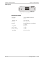
AMC-M/SF1/SC/R
AMC-R
LASER
CLASS
1
SIG
SC/ SM
LASER/ SF1
Figure A-30. AMC-M/SF1/SC/R
Technical Specifications
Wavelength
Transmit – 1310 nm, receive – 1550 nm
Connector
SC
Transmitter Type
Laser, WDM
Fiber Type
9/125, single mode
Protocols
TAXI, FDDI, Fast Ethernet, STS-1,
STS-3c/STM-1
Timing Mode
Retimed
Optical Output
-12 dBm
Receiver Sensitivity
-29 dBm
Typical Range
• 35 km (21.7 miles)
• 25 km (15.5 miles)
• 20 km (12.4 miles)
A-30
Fiber Optic Modules
AMC-101
Installation and Operation Manual
Appendix A Interface Modules
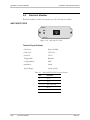
AMC-M/SF1/SC/T
AMC-T
LASER
CLASS
1
SIG
SC/ SM
LASER/ SF1
Figure A-31. AMC-M/SF1/SC/T
Technical Specifications
Wavelength
Transmit – 1310 nm, receive – 1550 nm
Connector
SC
Transmitter Type
Laser, WDM
Fiber Type
9/125, single mode
Protocols
Any two level optical protocols up to
155 Mbps
Timing Mode
Transparent
Optical Output
-12 dBm
Receiver Sensitivity
-29 dBm
Typical Range
• 35 km (21.7 miles)
• 25 km (15.5 miles)
• 20 km (12.4 miles)
AMC-101
Fiber Optic Modules
A-31
Appendix A Interface Modules
Installation and Operation Manual
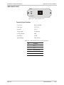
AMC-M/SF2/SC/R
AMC-R
LASER
CLASS
1
SIG
SC/ SM
LASER/ SF2
Figure A-32. AMC-M/SF2/SC/R
Technical Specifications
Wavelength
Transmit – 1550 nm, receive – 1310 nm
Connector
SC
Transmitter Type
Laser, WDM
Fiber Type
9/125, single mode
Protocols
TAXI, FDDI, Fast Ethernet, STS-1,
STS-3c/STM-1
Timing Mode
Retimed
Optical Output
-12 dBm
Receiver Sensitivity
-29 dBm
Typical Range
• 35 km (21.7 miles)
• 25 km (15.5 miles)
• 20 km (12.4 miles)
A-32
Fiber Optic Modules
AMC-101
Installation and Operation Manual
Appendix A Interface Modules
AMC-M/SF2/SC/T
AMC-T
LASER
CLASS
1
SIG
SC/ SM
LASER/ SF2
Figure A-33. AMC-M/SF2/SC/T
Technical Specifications
Wavelength
Transmit – 1550 nm, receive – 1310 nm
Connector
SC
Transmitter Type
Laser, WDM
Fiber Type
9/125, single mode
Protocols
Any two level optical protocols up to
155 Mbps
Timing Mode
Transparent
Optical Output
-12 dBm
Receiver Sensitivity
-29 dBm
Typical Range
• 35 km (21.7 miles)
• 25 km (15.5 miles)
• 20 km (12.4 miles)
AMC-101
Fiber Optic Modules
A-33
Appendix A Interface Modules
Installation and Operation Manual
AMC-M/SF3/R
AMC-R
LASER
CLASS
1
SIG
SC-APC/ SM
LASER/ SF3
Figure A-34. AMC-M/SF3/R
Technical Specifications
A-34
Wavelength
1310 nm, transmit and receive
Connector
SC/APC
Transmitter Type
Laser, single fiber
Fiber Type
9/125, single mode
Protocols
TAXI, FDDI, Fast Ethernet, STS-1,
STS-3c/STM-1
Timing Mode
Retimed
Optical Output
-12 dBm
Receiver Sensitivity
-27 dBm
Typical Range
20 km (12.4 miles)
Fiber Optic Modules
AMC-101
Installation and Operation Manual
Appendix A Interface Modules
AMC-M/SF3/T
AMC-T
LASER
CLASS
1
SIG
SC-APC/ SM
LASER/ SF3
Figure A-35. AMC-M/SF3/T
Technical Specifications
AMC-101
Wavelength
1310 nm, transmit and receive
Connector
SC/APC
Transmitter Type
Laser, single fiber
Fiber Type
9/125, single mode
Protocols
Any two level optical protocols up to
155 Mbps
Timing Mode
Transparent
Optical Output
-12 dBm
Receiver Sensitivity
-27 dBm
Typical Range
20 km (12.4 miles)
Fiber Optic Modules
A-35
Appendix A Interface Modules
A.2
Installation and Operation Manual
Electrical Modules
Electrical modules of AMC-101 operate over UTP, STP and coax cables.
AMC-M/UTP/155/R
AMC-R
SIG
UTP/ 155
Figure A-36. AMC-M/UTP/155/R
Technical Specifications
Connector
RJ-45, shielded
Cable Type
UTP Cat 5
Protocols
STS-3c
Timing Mode
Retimed
Coding Method
NRZ
Impedance
100Ω
Typical Range
100m (328 ft)
Table A-1. AMC-M/UTP/155/R Connector Pinout
A-36
Electrical Modules
Pin
Function
1
Tx (+)
2
Tx (-)
3, 4, 5, 6
Not connected
7
Rx (+)
8
Rx (-)
AMC-101
Installation and Operation Manual
Appendix A Interface Modules
AMC-M/UTP/155/T
AMC-T
SIG
UTP/ 155
Figure A-37. AMC-M/UTP/155/T
Technical Specifications
Connector
RJ-45, shielded
Cable Type
UTP Cat 5
Protocols
STS-3c
Timing Mode
Transparent
Coding Method
NRZ
Impedance
100Ω
Typical Range
50m (164 ft)
Table A-2. AMC-M/UTP/155/T Connector Pinout
AMC-101
Pin
Function
1
Tx (+)
2
Tx (-)
3, 4, 5, 6
Not connected
7
Rx (+)
8
Rx (-)
Electrical Modules
A-37
Appendix A Interface Modules
Installation and Operation Manual
AMC-M/STP/155/R
AMC-R
SIG
STP/ 155
Figure A-38. AMC-M/UTP/155/R
Technical Specifications
Connector
DB-9, female
Cable Type
STP Type 1
Protocols
STS-3c
Timing Mode
Retimed
Coding Method
NRZ
Impedance
150Ω
Typical Range
100m (328 ft)
Table A-3. AMC-M/STP/155/R Connector Pinout
A-38
Electrical Modules
Pin
Function
1
Rx (+)
2, 3, 4, 7, 8
Not connected
5
Tx (+)
6
Rx (-)
9
Tx (-)
AMC-101
Installation and Operation Manual
Appendix A Interface Modules
AMC-M/STP/155/T
AMC-T
SIG
STP/ 155
Figure A-39. AMC-M/UTP/155/T
Technical Specifications
Connector
DB-9, female
Cable Type
STP Type 1
Protocols
STS-3c
Timing Mode
Transparent
Coding Method
NRZ
Impedance
150Ω
Typical Range
50m (164 ft)
Table A-4. AMC-M/STP/155/T Connector Pinout
AMC-101
Pin
Function
1
Rx (+)
2, 3, 4, 7, 8
Not connected
5
Tx (+)
6
Rx (-)
9
Tx (-)
Electrical Modules
A-39
Appendix A Interface Modules
Installation and Operation Manual
AMC-M/UTP/100/R
AMC-R
SIG
UTP/ 100
Figure A-40. AMC-M/UTP/100/R
Technical Specifications
Connector
RJ-45, shielded
Cable Type
UTP Cat 5
Protocols
FDDI
Timing Mode
Retimed
Coding Method
NRZ
Impedance
100Ω
Typical Range
100m (328 ft)
Table A-5. AMC-M/UTP/155/R Connector Pinout
A-40
Electrical Modules
Pin
Function
1
Tx (+)
2
Tx (-)
3, 4, 5, 6
Not connected
7
Rx (+)
8
Rx (-)
AMC-101
Installation and Operation Manual
Appendix A Interface Modules
AMC-M/UTP/100/T
AMC-T
SIG
UTP/ 100
Figure A-41. AMC-M/UTP/100/T
Technical Specifications
Connector
RJ-45, shielded
Cable Type
UTP Cat 5
Protocols
FDDI
Timing Mode
Transparent
Coding Method
NRZ
Impedance
100Ω
Typical Range
50m (164 ft)
Table A-6. AMC-M/UTP/100/T Connector Pinout
AMC-101
Pin
Function
1
Tx (+)
2
Tx (-)
3, 4, 5, 6
Not connected
7
Rx (+)
8
Rx (-)
Electrical Modules
A-41
Appendix A Interface Modules
Installation and Operation Manual
AMC-M/CX/BNC/155/R
AMC-R
TX
RX
SIG
CX/ BNC/ 155
Figure A-42. AMC-M/CX/BNC/155/R
Technical Specifications
A-42
Connector
BNC, coax
Cable Type
Coaxial
Protocols
STS-3c, STM-1
Timing Mode
Retimed
Impedance
75Ω
Range Calculation
12.7 dB; 135m range is attainable when
using RG-59 B/U (at 78 MHz, in accordance
with the square root of frequency law)
Electrical Modules
AMC-101
Installation and Operation Manual
Appendix A Interface Modules
AMC-M/CX/DIN/155/R
AMC-R
TX
RX
SIG
CX/ DIN/ 155
Figure A-43. AMC-M/CX/DIN/155/R
Technical Specifications
AMC-101
Connector
DIN 47295, 1.6/5.6 coax
Cable Type
Coaxial
Protocols
STS-3c, STM-1
Timing Mode
Retimed
Impedance
75Ω
Range Calculation
12.7 dB; 135m range is attainable when
using RG-59 B/U (at 78 MHz, in accordance
with the square root of frequency law)
Electrical Modules
A-43
Appendix A Interface Modules
Installation and Operation Manual
AMC-M/10BT/B
AMC-R
TX LINK
RX COLL
10BT
Figure A-44. AMC-M/10BT/B
Technical Specifications
Connector
RJ-45, shielded
Cable Type
UTP Cat 5
Protocols
Ethernet (10BaseT), half or full duplex
Timing Mode
Retimed
Operation Mode
Ethernet bridge
Impedance
100Ω
Typical Range
100m (328 ft)
Table A-7. AMC-M/10BT/B Connector Pinout
Note
A-44
Pin
Function
1
Tx (+)
2
Tx (-)
3
Rx (+)
4, 5, 7, 8
Not connected
6
Rx (-)
The AMC-M/10BT/B modules require the modules of the same type installed at the
local and remote sites of the application.
Electrical Modules
AMC-101
24 Raoul Wallenberg St., Tel Aviv 69719, Israel
Tel: +972-3-6458181, Fax: +972-3-6483331, +972-3-6498250
E-mail: [email protected], Web site: www.rad.com
Customer Response Form
RAD Data Communications would like your help in improving its product documentation.
Please complete and return this form by mail or by fax or send us an e-mail with your
comments.
Thank you for your assistance!
AMC-101
Manual Name: ______________________________________________________________
333-200-03/06
Publication Number: __________________________________________________________
Please grade the manual according to the following factors:
Installation instructions
Operating instructions
Manual organization
Illustrations
The manual as a whole
Excellent
Good
Fair
Poor
Very Poor
❒
❒
❒
❒
❒
❒
❒
❒
❒
❒
❒
❒
❒
❒
❒
❒
❒
❒
❒
❒
❒
❒
❒
❒
❒
What did you like about the manual?
___________________________________________________________________________
___________________________________________________________________________
___________________________________________________________________________
___________________________________________________________________________
___________________________________________________________________________
Error Report
Type of Error(s)
❒
Incompatibility with product
or Problem(s):
❒
Difficulty in understanding text
❒
Regulatory information (Safety, Compliance, Warnings, etc.)
❒
Difficulty in finding needed information
❒
Missing information
❒
Illogical flow of information
❒
Style (spelling, grammar, references, etc.)
❒
Appearance
❒
Other _________
Please list the exact page numbers with the error(s), detail the errors you found (information missing,
unclear or inadequately explained, etc.) and attach the page to your fax, if necessary.
_________________________________________________________________________________________
_________________________________________________________________________________________
_________________________________________________________________________________________
_________________________________________________________________________________________
Please add any comments or suggestions you may have.
_________________________________________________________________________________________
_________________________________________________________________________________________
_________________________________________________________________________________________
You are:
❒
Distributor
❒
End user
❒
VAR
❒
Other ________________________
Who is your distributor?
_______________________________
Your name and company: ___________________________________________________________
Job title: __________________________________________________________________________
Address: __________________________________________________________________________
Direct telephone number and extension: _______________________________________________
Fax number: ______________________________________________________________________
E-mail: _____________________________________________________________________
www.rad.com
INTERNATIONAL HEADQUARTERS:
24 Raoul Wallenberg Street, Tel Aviv 69719, Israel, Tel: 972-3-6458181
Fax: 972-3-6498250, 972-3-6474436, Email: [email protected]
NORTH AMERICA HEADQUARTERS:
900 Corporate Drive, Mahwah, N.J. 07430, Tel: (201) 529-1100
Toll Free: 1-800-444-7234, Fax: (201) 529-5777, Email: [email protected]
Publication No. 333-200-03/06