1
SUMMIT.BK Page i Thursday, September 25, 1997 12:33 PM
Summit Switch
Installation and User
Guide
Extreme Networks, Inc.
10460 Bandley Drive
Cupertino, California 95014
(888) 257-3000
http://www.extremenetworks.com
Published September 1997
SUMMIT.BK Page ii Thursday, September 25, 1997 12:33 PM
Copyright © Extreme Networks, Inc., 1997. All rights reserved. No part of this documentation may be
reproduced in any form or by any means or used to make any derivative work (such as translation,
transformation, or adaptation) without permission from Extreme Networks, Inc.
Extreme Networks, ExtremeWare, Summit, and the Extreme Networks logo are trademarks of Extreme
Networks.
All other brand and product names are registered trademarks or trademarks of their respective
holders.
ii
SUMMIT.BK Page i Thursday, September 25, 1997 12:33 PM
PREFACE
This preface provides an overview of this guide, describes guide conventions, tells you
where to look for speciÞc information and lists other publications that may be useful.
INTRODUCTION
This guide provides the required information to install and conÞgure the Summit1 and
Summit2 Gigabit Ethernet Switch.
This guide is intended for use by network administrators who are responsible for
installing and setting up network equipment. It assumes a basic working knowledge of
¥ Local Area Networks (LANs)
¥ Ethernet concepts
¥ Ethernet switching and bridging concepts
¥ Simple Network Management Protocol (SNMP)
If the information in the Release Notes shipped with your Switch differs from the
information in this guide, follow the Release Notes.
TERMINOLOGY
When features, functionality, or operation is speciÞc to a particular model of the
Summit family, the model name is used (for example, Summit1 or Summit2).
SUMMIT SWITCH INSTALLATION
AND
USER GUIDE
I
SUMMIT.BK Page ii Thursday, September 25, 1997 12:33 PM
Explanations about features and operations that are the same among all members of the
Summit family simply refer to the product as the Summit.
CONVENTIONS
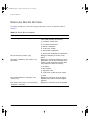
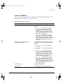
Table 1 and Table 2 list conventions that are used throughout this guide.
Table 1: Notice Icons
Icon
Notice Type
Alerts you to...
Note
Important features or instructions.
Caution
Risk of personal injury, system damage,
or loss of data.
Warning
Risk of severe personal injury.
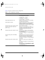
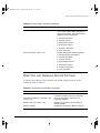
Table 2: Text Conventions
Convention
Description
Screen displays
This typeface represents information as it appears on the screen.
The words “enter”
and “type”
When you see the word “enter” in this guide, you must type
something, and then press the Return or Enter key. Do not press the
Return or Enter key when an instruction simply says “type.”
[Key] names
Key names appear in text in one of two ways:
■
Referred to by their labels, such as “the Return key” or “the
Escape key”
■
Written with brackets, such as [Return] or [Esc]
If you must press two or more keys simultaneously, the key names
are linked with a plus sign (+). Example:
Press [Ctrl]+[Alt]+[Del].
Words in italicized type
Italics emphasize a point or denote new terms at the place where
they are defined in the text.
Words in boldface type
Bold text denotes key features.
II
SUMMIT SWITCH INSTALLATION
AND
USER GUIDE
SUMMIT.BK Page iii Thursday, September 25, 1997 12:33 PM
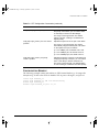
RELATED PUBLICATIONS
The command syntax is explained in Chapter 4.
RELATED PUBLICATIONS
The Summit documentation set includes the following:
¥ Summit Quick Reference Guide
¥ Summit Release Note
You may Þnd the following Web site of interest:
¥ Extreme Networks Home Page: http://www.extremenetworks.com/
SUMMIT SWITCH INSTALLATION
AND
USER GUIDE
III
SUMMIT.BK Page iv Thursday, September 25, 1997 12:33 PM
IV
SUMMIT SWITCH INSTALLATION
AND
USER GUIDE
SUMMIT.BK Page 1 Thursday, September 25, 1997 12:33 PM
1
Summit Overview
This chapter describes the following:
¥ Summit1 and Summit2 features
¥ How to use the Summit family of switches in your network conÞguration
¥ Summit front views
¥ Summit rear view
¥ Factory default settings
ABOUT THE SUMMIT FAMILY OF SWITCHES
Network managers are currently faced with the challenge of creating networks that can
provide ultra-fast speed and high performance to serve the needs of todayÕs network
users, while simultaneously preserving the investment they have made in Ethernet and
Fast Ethernet technology.
By addressing the entire spectrum of Ethernet data rates (10/100/1000 Mbps), the
Summit family of LAN switches enables you to introduce high-speed Gigabit Ethernet
backbones into your existing network, while maintaining established connections to the
10 Mbps and 100 Mbps segments that already exist.
SUMMIT SWITCH INSTALLATION
AND
USER GUIDE
1-1
SUMMIT.BK Page 2 Thursday, September 25, 1997 12:33 PM
SUMMIT OVERVIEW
SUMMARY OF FEATURES
The Summit family of switches is comprised of two models: the Summit1 and the
Summit2.
Both switches have the following features:
¥ Support for 128K addresses in the Switch forwarding database
¥ Fully nonblocking operation
Ñ All ports transmit and receive packets at wire speed
¥ Autonegotiation for half- or full-duplex operation
¥ Optional redundant power supply
¥ Redundant physical Gigabit Ethernet backbone connection
¥ Virtual local area networks (VLANs) including support for 802.1Q
¥ Quality of Service (QoS)
¥ Spanning Tree Protocol (STP) (IEEE 802.1D) with multiple STP domains
¥ Wirespeed Internet Protocol (IP) routing via Routing Information Protocol (RIP)
version 1 and RIP version 2
¥ Integrated network management
¥ Console connection
¥ Telnet connection
¥ Web interface
¥ Simple Network Management Protocol (SNMP) support
PORT CONNECTIONS
The Summit1 provides eight Gigabit Ethernet ports. Six of the ports are Þxed
1000Base-SX ports using 850nm duplex SC connectors. Two of the ports are modular,
and support the standard Gigabit Interface Connector (GBIC). This enables you to select
various types of Þber and copper modules to support longer distances or lower cost.
The Summit1 can be ordered with either two 1000Base-SX or two 1000Base-LX GBIC
transceivers already installed. GBIC transceivers can also be ordered separately.
1-2
SUMMIT SWITCH INSTALLATION
AND
USER GUIDE
SUMMIT.BK Page 3 Thursday, September 25, 1997 12:33 PM
SUMMARY
OF
FEATURES
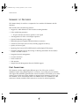
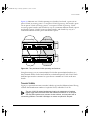
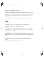
Figure 1-1 shows the front view of the Summit1.
Unit status LEDs
Port status LEDs
Gigabit Ethernet ports
Gigabit Ethernet ports
Figure 1-1: Summit1 front view
The Summit2 is a workgroup switch featuring sixteen 10Base-T/100Base-TX ports, two
Gigabit Ethernet uplinks, and one redundant Gigabit Ethernet uplink. The
10Base-T/100Base-TX ports use standard RJ-45 connectors. They are autosensing for
10/100 Mbps operation, as well as half- or full-duplex operation. The Gigabit Ethernet
interfaces support the GBIC connector, and ship with standard 1000Base-SX, 850nm
GBIC modules. Additional cable types are also supported.
Figure 1-2 shows the front view of the Summit2
Port status LEDs
10/100 Mbps ports
Unit status LEDs
Gigabit Ethernet ports
Figure 1-2: Summit2 front view
SUMMIT SWITCH INSTALLATION
AND
USER GUIDE
1-3
SUMMIT.BK Page 4 Thursday, September 25, 1997 12:33 PM
SUMMIT OVERVIEW
FULL-DUPLEX
The Summit Switch provides full-duplex support for all ports. Full-duplex allows
frames to be transmitted and received simultaneously and, in effect, doubles the
bandwidth available on a link. All 10/100 Mbps ports on the Summit autonegotiate for
half- or full-duplex operation.
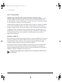
PORT REDUNDANCY
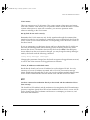
The Summit2 has an optional redundant Gigabit Ethernet port. Using the redundant
port, you can dual-home the Summit2 to one or two Switches. Figure 1-3 illustrates a
Summit2 dual-homed to two different Switches.
Dual-homed
Backup
Active
Figure 1-3: Dual-homing configuration
In the event that the active port fails or loses link status, the redundant port is
automatically activated. When the primary port resumes operation, the redundant port
becomes inactive. The redundant port cannot be used for load sharing.
VIRTUAL LANS (VLANS)
The Summit has a VLAN feature that enables you to construct your broadcast domains
without being restricted by physical connections. Up to 255 VLANs can be deÞned on
the Summit. A VLAN is a group of location- and topology-independent devices that
communicate as if they were on the same physical local area network (LAN).
Implementing VLANs on your network has the following three advantages:
1-4
SUMMIT SWITCH INSTALLATION
AND
USER GUIDE
SUMMIT.BK Page 5 Thursday, September 25, 1997 12:33 PM
SUMMARY
OF
FEATURES
¥ It helps to control broadcast trafÞc. If a device in VLAN marketing transmits a
broadcast frame, only VLAN marketing devices receive the frame.
¥ It provides extra security. Devices in VLAN marketing can only communicate with
devices on VLAN sales using a device that provides routing services.
¥ It eases the change and movement of devices on networks. If a device in VLAN
marketing is moved to a port in another part of the network, all you must do is
specify that the new port belongs to VLAN marketing.
For more information on VLANs, refer to Chapter 5.
SPANNING TREE PROTOCOL (STP)
The Summit supports the IEEE 802.1D Spanning Tree Protocol (STP), which is a
bridge-based mechanism for providing fault tolerance on networks. STP enables you to
implement parallel paths for network trafÞc, and ensure the following:
¥ Redundant paths are disabled when the main paths are operational.
¥ Redundant paths are enabled if the main trafÞc paths fail.
The Summit supports up to 64 Spanning Tree Domains (STPDs).
For more information on STP, refer to Chapter 7.
QUALITY OF SERVICE (QOS)
The Summit has Quality of Service (QoS) features that enable you to specify service
levels for different trafÞc groups. By default, all trafÞc is assigned with the ÒnormalÓ
QoS proÞle. If needed, you can conÞgure some trafÞc to have different guaranteed
minimum bandwidth, maximum bandwidth, and priority.
For more information on Quality of Service, refer to Chapter 8.
SUMMIT SWITCH INSTALLATION
AND
USER GUIDE
1-5
SUMMIT.BK Page 6 Thursday, September 25, 1997 12:33 PM
SUMMIT OVERVIEW
IP UNICAST ROUTING
The Summit can route IP trafÞc between the VLANs that are conÞgured as virtual
router interfaces. Both dynamic and static IP routes are maintained in the routing table.
RIP version 1 and RIP version 2 are supported.
For more information on IP unicast routing, see Chapter 9.
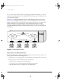
NETWORK CONFIGURATION EXAMPLES
This section describes where to position the Summit1 and Summit2 within your
network.
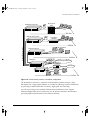
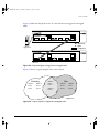
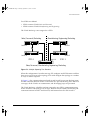
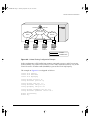
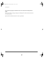
One common use of the Summit is on a Gigabit Ethernet backbone. Figure 1-4 shows an
example of a Gigabit Ethernet backbone within a building.
1-6
SUMMIT SWITCH INSTALLATION
AND
USER GUIDE
SUMMIT.BK Page 7 Thursday, September 25, 1997 12:33 PM
NETWORK CONFIGURATION EXAMPLES
Regional wiring closet
Workgroup
hubs
PCs
4th floor
Regional wiring closet
Workgroup
switches
PCs
Gigabit Ethernet risers
3rd floor
Power workgroup
Workstations
2nd floor
Backbone
Meshed campus backbone
Router
Internet
Workstations
1st floor
Figure 1-4: Summit family used in a backbone configuration
The Summit2 on each ßoor is connected to the backbone Summit1 using a 1 Gbps,
full-duplex link. Using Gigabit Ethernet as a backbone technology removes bottlenecks
by providing scalable bandwidth, low-latency, high-speed data switching.
As well as providing a fast-switched backbone between Ethernet LANs, Gigabit
Ethernet-equipped Þle servers and devices may be directly attached to the Summit1,
providing improved performance to the Ethernet desktop.
SUMMIT SWITCH INSTALLATION
AND
USER GUIDE
1-7
SUMMIT.BK Page 8 Thursday, September 25, 1997 12:33 PM
SUMMIT OVERVIEW
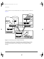
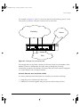
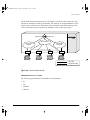
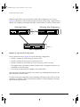
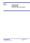
Another common use for the Summit family is in a campus environment, as shown in
Figure 1-5.
Building 2
PCs
Building 1
Intranet/Internet
Dual-homing
Loadbalanced
links
Meshed
backbone
Building 3
Workstations
Figure 1-5: Summit family used in a campus environment
The Summit1 switches located in each building form a meshed backbone, providing
load balancing and redundancy. In addition, the Summit2 Switch in Building 2 is
dual-homed to the Summit1 located in Building 1 and to the Summit1 located in
Building 2.
1-8
SUMMIT SWITCH INSTALLATION
AND
USER GUIDE
SUMMIT.BK Page 9 Thursday, September 25, 1997 12:33 PM
SUMMIT1 FRONT VIEW
SUMMIT1 FRONT VIEW
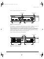
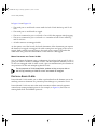
Figure 1-6 shows the Summit1 front view.
Unit status LEDs
Port status LEDs
Gigabit Ethernet ports
Gigabit Ethernet ports
Figure 1-6: Summit1 front view
PORTS
The Summit1 has eight Gigabit Ethernet ports. Six of the ports use SC connectors and
support 1000Base-SX over 850nm Þber-optic cable. Ports 1 and 8 have GBIC connectors
and support the media types and distances listed in Table 1-1.
Table 1-1: Summit1 Supported Media Distances for GBIC Connectors
Distance
50/125 micro
Multimode Fiber
62.5/125 micron
Multimode Fiber
Single-mode Fiber
850nm Multimode
Optics
550 Meters
260 Meters
Not supported
1300nm
Single-mode Optics
550 Meters
440 Meters
3000 Meters
Gigabyte Type
For more information on 1000Base-SX and 1000Base-LX link characteristics,
refer to IEEE Draft P802.3z/D3.1, Table 38-8.
SUMMIT SWITCH INSTALLATION
AND
USER GUIDE
1-9
SUMMIT.BK Page 10 Thursday, September 25, 1997 12:33 PM
SUMMIT OVERVIEW
LEDS
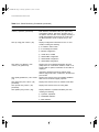
Table 1-2 describes the light emitting diode (LED) behavior on the Summit1.
Table 1-2: Summit1 LEDs
LED
Color
Indicates
Power
Green
The Summit1 is powered up.
Yellow
The Summit1 is indicating a power, overheat, or fan failure.
MGMT
Green flashing
■
Slow
■
Power On Self Test (POST) in progress.
■
Medium
■
The Summit1 is operating normally.
■
Fast
■
Software download in progress.
Yellow
The Summit1 has failed its POST.
Port Status LEDs
Packet
Status
1-10
Yellow
Frames are being transmitted/received on this port.
Off
No activity on this port.
Green on
Link is present; port is enabled;
full-duplex operation.
Green flashing
Link is present; port is disabled.
Off
Link is not present.
SUMMIT SWITCH INSTALLATION
AND
USER GUIDE
SUMMIT.BK Page 11 Thursday, September 25, 1997 12:33 PM
SUMMIT2 FRONT VIEW
SUMMIT2 FRONT VIEW
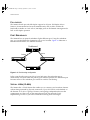
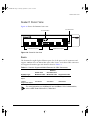
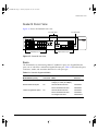
Figure 1-7 shows the Summit2 front view.
Port status LEDs
Unit status LEDs
Gigabit Ethernet ports
10/100 Mbps ports
Figure 1-7: Summit2 front view
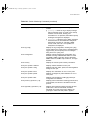
PORTS
The Summit2 has 16 autosensing 10Base-T/100Base-TX ports, two Gigabit Ethernet
ports, one of which has a redundant Gigabit Ethernet port. Table 1-3 describes the ports,
connectors, media, and maximum distances for each port type.
Table 1-3: Summit2 Supported Media
Media Module (Ports)
Connector Media
Maximum
Distance
RJ-45
RJ-45
100 Meters
Category 5 Cable (at 100Mbps)
Category 3 Cable (at 10Mbps)
850nm Multimode Optics
1300nm Singlemode Optics
SUMMIT SWITCH INSTALLATION
AND
USER GUIDE
SC
SC
50u/125 Multimode Fiber
550 Meters
62.5u/125 Multimode Fiber
260 Meters
50u/125 Multimode Fiber
550 Meters
62.5u/125 Multimode Fiber
440 Meters
10u Singlemode Fiber
3000 Meters
1-11
SUMMIT.BK Page 12 Thursday, September 25, 1997 12:33 PM
SUMMIT OVERVIEW
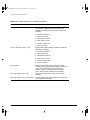
LEDS
Table 1-4 describes the LED behavior on the Summit2.
Table 1-4: Summit2 LEDs
LED
Color
Indicates
Power
Green
The Summit2 is powered up.
Yellow
The Summit2 is indicating a power, overheat, or fan failure.
MGMT
Green flashing
■
Slow
■
Power On Self Test (POST) in progress.
■
Medium
■
The Summit2 is operating normally.
■
Fast
■
Software download in progress.
Yellow
The Summit2 has failed its POST.
10/100Mbps Port Status LEDs
Green
Link is present; port is enabled.
Yellow
Frames are being transmitted/received on this port.
Green flashing
Link is present; port is disabled.
Off
Link is not present.
Gigabit Ethernet Port Status LEDs
Packet
Yellow
Frames are being transmitted/received on this port.
No activity on this port.
Off
Status
1-12
Green on
Link is present; port is enabled;
full-duplex operation.
Green flashing
Link is present; port is disabled.
Off
Link is not present.
SUMMIT SWITCH INSTALLATION
AND
USER GUIDE
SUMMIT.BK Page 13 Thursday, September 25, 1997 12:33 PM
SUMMIT REAR VIEW
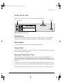
SUMMIT REAR VIEW
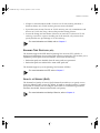
Figure 1-8 shows the rear view for the Summit1 and the Summit2.
Power socket and fuse
RPS port
U
L
C
Console port
U
L
!
MODEL/NUMBER
MADE IN USA
PART NUMBER
SERIAL NUMBER
MAC ADDRESS
130001-00 Rev.03
Figure 1-8: Summit rear view
POWER SOCKET
The Summit automatically adjusts to the supply voltage. The power supply operates
down to 90 V. The fuse is suitable for both 110 V AC and 220-240 V AC operation.
SERIAL NUMBER
You may need this serial number for fault-reporting purposes.
CONSOLE PORT
Use the console port (9-pin, ÒDÓ type connector) for connecting a terminal and carrying
out local out-of-band management.
REDUNDANT POWER SUPPLY PORT
The redundant power supply (RPS) port is used to connect to a Summit RPS. The
Summit RPS provides a redundant power source to the Summit. If the primary power
source for the Switch fails, the Summit RPS takes over, ensuring uninterrupted network
operation.
In addition, when connected to a Summit RPS, the Summit Switch can provide status
on power and fan operation of the RPS through SNMP and the command-line interface.
The Summit RPS can simultaneously provide power for up to two Summit Switches.
SUMMIT SWITCH INSTALLATION
AND
USER GUIDE
1-13
SUMMIT.BK Page 14 Thursday, September 25, 1997 12:33 PM
SUMMIT OVERVIEW
MAC ADDRESS
This label shows the unique Ethernet MAC address assigned to this device.
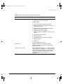
FACTORY DEFAULTS
Table 1-5 shows factory defaults for the Summit features.
Table 1-5: Summit Factory Defaults
Item
Default Setting
Port status
Enabled on all ports.
Serial or Telnet user account
admin with no password and user with no password.
Console port configuration
9600 baud, eight data bits, one stop bit, no parity, XON/XOFF
flow control enabled.
Web network management
Enabled.
SNMP read community string
public.
SNMP write community string
private.
RMON history session
Enabled.
RMON alarms
Disabled.
BOOTP
Enabled on the default VLAN (default).
QoS
All traffic is part of the default queue.
802.1p priority
Recognition enabled.
Virtual LANs
One VLAN named default; all ports belong to the default
VLAN. The default VLAN belongs to the STPD named s0.
802.1Q tagging
All packets are untagged on the default VLAN (default)
Spanning Tree Protocol
Disabled; one STPD (s0).
IP Routing
Disabled.
Forwarding database aging
period
300 seconds (5 minutes).
1-14
SUMMIT SWITCH INSTALLATION
AND
USER GUIDE
SUMMIT.BK Page 1 Thursday, September 25, 1997 12:33 PM
2
Installation and Setup
This chapter describes the following:
¥ How to decide where to install the Summit
¥ Gigabit Ethernet conÞguration rules
¥ How to install the Switch in a rack or free-standing
¥ How to connect equipment to the console port
¥ How to check the installation using the Power On Self-Test (POST)
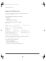
FOLLOWING SAFETY INFORMATION
Before installing or removing any components of the Switch, or before carrying out any
maintenance procedures, you must read the safety information provided in Appendix A
of this guide.
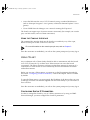
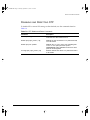
DETERMINING THE SWITCH LOCATION
The Summit is suited for use in the ofÞce, where it can be free-standing or mounted in a
standard 19-inch equipment rack. Alternatively, the device can be rack-mounted in a
wiring closet or equipment room. Two mounting brackets are supplied with the Switch.
SUMMIT SWITCH INSTALLATION
AND
USER GUIDE
2-1
SUMMIT.BK Page 2 Thursday, September 25, 1997 12:33 PM
INSTALLATION
AND
SETUP
When deciding where to install the Switch, ensure that:
¥ The Switch is accessible and cables can be connected easily.
¥ Water or moisture cannot enter the case of the unit.
¥ Air-ßow around the unit and through the vents in the side of the case is not
restricted. You should provide a minimum of 25mm (1-inch) clearance.
¥ No objects are placed on top of the unit.
¥ Units are not stacked more than four high if the Switch is free-standing.
CONFIGURATION RULES
The connectors, supported media types, and maximum distances for the Summit family
are described in Chapter 1.
INSTALLING THE SUMMIT
The Summit can be mounted in a rack, or placed free-standing on a tabletop.
RACK MOUNTING
The Switch is 2U high and will Þt in most standard 19-inch racks.
The rack mount kits must not be used to suspend the Switch from under a table
or desk, or attach it to a wall.
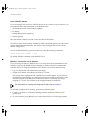
To rack mount the Summit, follow these steps:
1 Place the Switch the right way up on a hard ßat surface, with the front facing
toward you.
2 Remove the existing screws from the sides of the chassis and retain for Step 4.
3 Locate a mounting bracket over the mounting holes on one side of the unit.
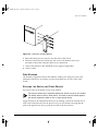
4 Insert the four screws and fully tighten with a suitable screwdriver, as shown in
Figure 2-1.
2-2
SUMMIT SWITCH INSTALLATION
AND
USER GUIDE
SUMMIT.BK Page 3 Thursday, September 25, 1997 12:33 PM
INSTALLING
THE
SUMMIT
Figure 2-1: Fitting the mounting bracket
5 Repeat the three previous steps for the other side of the Switch.
6 Insert the Switch into the 19-inch rack and secure with suitable screws (not
provided). Ensure that ventilation holes are not obstructed.
7 Connect the Summit to the redundant power supply (if applicable).
8 Connect cables.
FREE-STANDING
The Summit is supplied with four self-adhesive rubber pads. Apply the pads to the
underside of the device by sticking a pad in the marked area at each corner of the
Switch.
STACKING THE SWITCH AND OTHER DEVICES
Up to four units can be placed on top of one another.
This section relates only to physically placing the devices on top of one another.
The Switch does not form a stack (that is, a number of devices linked together
with special expansion cables to form a single logical device).
Apply the pads to the underside of the device by sticking a pad in the marked area at
each corner of the Switch. Place the devices on top of one another, ensuring that the
pads of the upper device line up with the recesses of the lower device.
SUMMIT SWITCH INSTALLATION
AND
USER GUIDE
2-3
SUMMIT.BK Page 4 Thursday, September 25, 1997 12:33 PM
INSTALLATION
AND
SETUP
CONNECTING EQUIPMENT TO THE CONSOLE PORT
Connection to the console port is used for direct local management. The Switch console
port settings are set as follows:
¥ Baud rate Ñ 9600
¥ Data bits Ñ 8
¥ Stop bit Ñ 1
¥ Parity Ñ None
¥ Flow control Ñ XON/XOFF
The terminal connected to the console port on the Switch must be conÞgured with the
same settings. This procedure will be described in the documentation supplied with the
terminal.
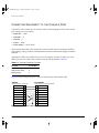
Appropriate cables are available from your local supplier. In order to make your own
cables, pin-outs for a DB-9 male console connector are described in Table 2-1.
Table 2-1: Console Connector Pin-Outs
Function
Pin Number
TXD (transmit data)
3
RXD (receive data)
2
GND (ground)
5
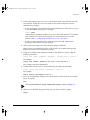
Figure 2-2 shows the pin-outs for a 9-pin to RS-232 25-pin null-modem cable.
Summit
PC/Terminal
Cable connector: 9-pin female
Screen
TxD
RxD
Ground
RTS
CTS
DSR
DCD
DTR
Shell
3
2
5
7
8
6
1
4
Cable connector: 25-pin male/female
1
3
2
7
4
20
5
6
8
Screen
RxD
TxD
Ground
RTS
DTR
CTS
DSR
DCD
Figure 2-2: Null-modem cable pin-outs
2-4
SUMMIT SWITCH INSTALLATION
AND
USER GUIDE
SUMMIT.BK Page 5 Thursday, September 25, 1997 12:33 PM
POWERING-UP
THE
SWITCH
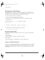
Figure 2-3 shows the pin-outs for a 9-pin to 9-pin PC-AT null-modem serial cable.
Summit
PC-AT Serial Port
Cable connector: 9-pin female
Screen
DTR
TxD
RxD
CTS
Ground
DSR
RTS
DCD
Shell
4
3
2
8
5
6
7
1
Cable connector: 9-pin female
Shell
1
2
3
4
5
6
7
8
Screen
DCD
RxD
TxD
DTR
Ground
DSR
RTS
CTS
Figure 2-3: PC-AT serial null-modem cable pin-outs
POWERING-UP THE SWITCH
To turn on power to the Switch, connect the power cable to the Switch and then to the
wall outlet, and turn the on/off switch to the on position.
CHECKING THE INSTALLATION
After turning on power to the Summit, the device performs a Power On Self-Test
(POST).
During the POST, all ports are temporarily disabled, the packet LED is off, the power
LED is on, and the MGMT LED ßashes. The MGMT LED ßashes until the Switch has
successfully passed the POST.
If the Switch passes the POST, the MGMT LED blinks at a slow rate (1 blink per
second). If the Switch fails the POST, the MGMT LED shows a solid yellow light.
For more information on the LEDs, refer to Table 1-2 and Table 1-4.
SUMMIT SWITCH INSTALLATION
AND
USER GUIDE
2-5
SUMMIT.BK Page 6 Thursday, September 25, 1997 12:33 PM
INSTALLATION
AND
SETUP
LOGGING IN FOR THE
FIRST TIME
After the Summit has completed the POST, it is operational. Once operational, you can
log in to the Switch and conÞgure an IP address for the default VLAN (named default).
To manually conÞgure the IP settings, perform the following steps:
1 Connect a terminal or workstation running terminal-emulation software to the
console port.
2 At your terminal, press [Return] one or more times until you see the login prompt.
3 At the login prompt, enter the default user name admin to log on with administrator
privileges. For example:
login: admin
Administrator capabilities allow you to access all Switch functions.
For more information on Switch security, refer to Chapter 3.
4 At the password prompt, press [Return].
The default name, admin, has no password assigned. When you have successfully
logged on to the Switch, the command-line prompt displays the name of the Switch
in its prompt.
5 Assign an IP address and subnetwork mask for VLAN default by typing
config vlan default ipaddress 123.45.67.8 255.255.255.0
Your changes take effect immediately.
6 Save your conÞguration changes so that they will be in effect after the next Switch
reboot, by typing
save
For more information on saving configuration changes, refer to Chapter 11.
7 When you are Þnished using the facility, logout of the Switch by typing
logout
After two incorrect login attempts, the Summit locks you out of the login facility.
You must wait a few minutes before attempting to log in again.
2-6
SUMMIT SWITCH INSTALLATION
AND
USER GUIDE
SUMMIT.BK Page 1 Thursday, September 25, 1997 12:33 PM
3
Accessing The Switch
This chapter provides the following required information to begin managing the
Summit:
¥ ConÞguring the Switch for management
¥ Switch management methods
¥ ConÞguring SNMP
¥ ConÞguring Switch ports
In order for configuration changes to be retained through a Switch power cycle
or reboot, you must issue a SAVE command after you have made the change.
For more information on the SAVE command, refer to Chapter 11.
CONFIGURING MANAGEMENT ACCESS
The Summit supports the following two level levels of management:
¥ User
¥ Administrator
A user-level account has viewing access to all manageable parameters, with the
exception of the following:
¥ User account database
¥ SNMP community strings
SUMMIT SWITCH INSTALLATION
AND
USER GUIDE
3-1
SUMMIT.BK Page 2 Thursday, September 25, 1997 12:33 PM
ACCESSING THE SWITCH
A user-level account can use the ping command to test device reachability, and change
the password assigned to the account name. If you have logged on with user
capabilities, the command-line prompt will end with a (>) sign. For example:
Summit1:2>
An administrator-level account can view and change all Switch parameters. It can also
add and delete users, and change the password associated with any account name. The
administrator can disconnect a management session that has been established by way of
a Telnet connection. If this happens, the user logged on by way of the Telnet connection
is notiÞed that the session has been terminated.
If you have logged on with administrator capabilities, the command-line prompt will
end with a (#) sign. For example:
Summit1:18#
The prompt text is taken from the SNMP sysname setting. The number that follows the
colon indicates the sequential line/command number.
If an asterisk (*) appears in front of the command-line prompt, it indicates that you
have outstanding conÞguration changes that have not been saved. For example:
*Summit1:19#
For more information on saving configuration changes, refer to Chapter 11.
DEFAULT ACCOUNTS
By default, the Switch is conÞgured with two accounts, as shown in Table 3-1.
Table 3-1: Default Accounts
Account Name
Access Level
admin
This user can access and change all manageable
parameters. The admin account cannot be deleted.
user
This user can view (but not change) all manageable
parameters, with the following exceptions:
■
This user cannot view the user account database.
■
This user cannot view the SNMP community strings.
This user has access to the ping command.
3-2
SUMMIT SWITCH INSTALLATION
AND
USER GUIDE
SUMMIT.BK Page 3 Thursday, September 25, 1997 12:33 PM
CONFIGURING MANAGEMENT ACCESS
CHANGING
THE
DEFAULT PASSWORD
Default accounts do not have passwords assigned to them. Passwords must have a
minimum of 4 characters and can have a maximum of 12 characters.
Passwords are case-sensitive.
To add a password to the default admin account, follow these steps:
1 Log in to the Switch using the name admin.
2 At the password prompt, press [Return].
3 Add a default admin password by typing the following:
config account admin
4 Enter the new password at the prompt.
5 Re-enter the new password at the prompt.
To add a password to the default user account, follow these steps:
1 Log in to the Switch using the name admin.
2 At the password prompt, press [Return].
3 Add a default user password by typing the following:
config account user
4 Enter the new password at the prompt.
5 Re-enter the new password at the prompt.
If you forget your password while logged out of the command-line interface,
contact your local technical support representative, who will advise on your next
course of action.
CREATING A MANAGEMENT ACCOUNT
The Switch can have a total of three management accounts. You can use the default
names (admin and user), or you can create new names and passwords for the accounts.
Passwords must have a minimum of 4 characters and can have a maximum of 12
characters.
The account name “admin” cannot be deleted.
SUMMIT SWITCH INSTALLATION
AND
USER GUIDE
3-3
SUMMIT.BK Page 4 Thursday, September 25, 1997 12:33 PM
ACCESSING THE SWITCH
To create a new account, follow these steps:
1 Log in to the Switch as admin.
2 At the password prompt, press [Return].
3 Add a new user by using the following command:
create account [admin | user] <username>
4 Enter the password at the prompt.
5 Re-enter the password at the prompt.
VIEWING SWITCH ACCOUNTS
To view the accounts that have been created, you must have administrator privileges.
Enter the following to see the accounts:
show account
Output from the show accounts command is as follows:
#show accounts
User Name
------------admin
user
DELETING
A
Access
-----R/W
RO
LoginOK
------0
0
Failed
-----0
0
Session
--------
SWITCH ACCOUNT
To delete a Switch account, you must have administrator privileges. Use the following
command to delete an account:
delete account <username>
METHODS OF MANAGING THE SUMMIT
You can manage the Summit using the following methods:
¥ Access the command-line interface by connecting a terminal (or workstation with
terminal-emulation software) to the Summit console port.
¥ Access the command-line interface over a TCP/IP network using a Telnet
connection.
3-4
SUMMIT SWITCH INSTALLATION
AND
USER GUIDE
SUMMIT.BK Page 5 Thursday, September 25, 1997 12:33 PM
USING TELNET
¥ Access the Web interface over a TCP/IP network, using a standard Web browser
(such as Netscape Navigatorª 3.0 or greater, or Microsoft Internet Explorerª 3.0 or
greater).
¥ Use an SNMP Network Manager over a network running the IP protocol.
The Switch can support up to four user sessions concurrently (for example, one console
port, one Web session, and two Telnet connections).
USING THE CONSOLE INTERFACE
The command-line interface built into the Switch is accessible by way of the 9-pin,
RS-232 console port located on the rear of the unit.
For more information on the console port pin-outs, refer to Chapter 2.
Once the connection is established, you will see the system prompt and you may log in.
USING TELNET
Any workstation with a Telnet facility should be able to communicate with the Switch
over a TCP/IP network. Up to three active Telnet sessions can access the Switch
concurrently. The Telnet connection will time out after three minutes of inactivity. If a
connection to a Telnet session is lost inadvertently, the Switch terminates the session
within three minutes.
Before you can start a Telnet session, you must set up the IP parameters described in
the section ÒConÞguring Switch IP Parameters,Ó later in this chapter. Telnet is enabled
by default.
To open the Telnet session, you must specify the IP address of the device that you want
to manage. Check the user manual supplied with the Telnet facility if you are unsure of
how to do this.
Once the connection is established, you will see the system prompt and you may log in.
CONFIGURING SWITCH IP PARAMETERS
In order to manage the Switch by way of a Telnet connection or by using an SNMP
Network Manager, you must conÞgure the Switch IP parameters.
SUMMIT SWITCH INSTALLATION
AND
USER GUIDE
3-5
SUMMIT.BK Page 6 Thursday, September 25, 1997 12:33 PM
ACCESSING THE SWITCH
USING
A
BOOTP SERVER
If you are using IP and you have a BOOTP server set up correctly on your network, you
must add the following information to the BOOTP server:
¥ Switch Media Access Control (MAC) address
¥ IP address
¥ Subnet address mask (optional)
¥ Default gateway
The Switch MAC address is found on the rear label of the Switch.
Once this is done, the IP address, subnetwork mask, and default gateway for the Switch
will be downloaded automatically. You can then start managing the Switch without
further conÞguration.
You can enable BOOTP on a per-VLAN basis by using the following command:
enable bootp vlan [<name> | all]
By default, BOOTP is enabled on the default VLAN.
MANUALLY CONFIGURING
THE
IP SETTINGS
If you are using IP without a BOOTP server, you must enter the IP parameters for the
Switch in order for the SNMP Network Manager or Telnet software to communicate
with the device. To assign IP parameters to the Switch, you must do the following:
¥ Log in to the Switch with administrator privileges.
¥ Assign an IP address and subnetwork mask to a VLAN.
The Switch comes conÞgured with a default VLAN named default. To use Telnet or
an SNMP Network Manager, you must have at least one VLAN on the Switch, and it
must be assigned an IP address and subnetwork mask. IP addresses are always
assigned to a VLAN. The Summit can be assigned multiple IP addresses.
For information on creating and configuring VLANs, refer to Chapter 5.
To manually conÞgure the IP settings, perform the following steps:
1 Connect a terminal or workstation running terminal emulation software to the
console port.
2 At your terminal, press [Return] one or more times until you see the login prompt.
3-6
SUMMIT SWITCH INSTALLATION
AND
USER GUIDE
SUMMIT.BK Page 7 Thursday, September 25, 1997 12:33 PM
USING TELNET
3 At the login prompt, enter your user name and password. Note that they are both
case-sensitive. Ensure that you have entered a user name and password with
administrator privileges.
Ñ If you are logging in for the Þrst time, use the default user name admin to log in
with administrator privileges. For example:
login: admin
Administrator capabilities enable you to access all Switch functions. The default
user names have no passwords assigned. For more information on switch
security, refer to ÒConÞguring Management Access,Ó on page 3-1.
Ñ If you have been assigned a user name and password with administrator
privileges, enter them at the login prompt.
4 At the password prompt, enter the password and press [Return].
When you have successfully logged in to the Switch, the command-line prompt
displays the name of the Switch in its prompt.
5 Assign an IP address and subnetwork mask for the default VLAN by using the
following command:
config vlan <name> ipaddress <ipaddress> {<subnet_mask>} {<metric>}
For example:
config vlan default ipaddress 123.45.67.8 255.255.255.0 1
Your changes take effect immediately.
6 ConÞgure the default route for the Switch using the following command:
config iproute add default <ipaddress> {<metric>}
For example:
config iproute add default 123.0.0.1
7 Save your conÞguration changes so that they will be in effect after the next Switch
reboot, by typing
save
For more information on saving configuration changes, refer to Chapter 11.
8 When you are Þnished using the facility, log out of the Switch by typing
logout
SUMMIT SWITCH INSTALLATION
AND
USER GUIDE
3-7
SUMMIT.BK Page 8 Thursday, September 25, 1997 12:33 PM
ACCESSING THE SWITCH
DISCONNECTING A TELNET SESSION
The administrator-level account can disconnect a management session that has been
established by way of a Telnet connection. If this happens, the user logged in by way of
the Telnet connection is notiÞed that the session has been terminated.
To terminate a Telnet session, follow these steps:
1 Log in to the Switch with administrator privileges.
2 Determine the session number of the session you want to terminate by typing
show session
Sample output from the show session command is as follows:
show session:
0
4
Wed Sep 17 20:48:38 1997
Wed Sep 17 21:52:16 1997
admin
admin
console serial
telnet 192.208.37.26
3 Terminate the session by using the following command:
clear session <session_number>
DISABLING TELNET ACCESS
By default, Telnet services are enabled on the Switch. You can choose to disable Telnet
by entering
disable telnet
To re-enable Telnet on the Switch, at the console port enter
enable telnet
You must be logged in as an administrator to enable or disable Telnet.
USING THE WEB INTERFACE
Any properly conÞgured standard Web browser that supports frames (such as Netscape
Navigator 3.0 or Microsoft Internet Explorer 3.0) can manage the Switch over a TCP/IP
network. To use the Web interface, at least one VLAN on the Switch must be assigned
an IP address.
3-8
SUMMIT SWITCH INSTALLATION
AND
USER GUIDE
SUMMIT.BK Page 9 Thursday, September 25, 1997 12:33 PM
USING
THE
WEB INTERFACE
For more information on assigning an IP address, refer to “Configuring Switch IP
Parameters,” on page 3-5.
The default home page of the Switch can be accessed using the following address:
http://<ipaddress>
When you access the home page of the Switch, you are presented with the Logon
screen.
SUMMIT MANAGEMENT INTERFACE SCREEN
After logging in to the Switch, the Web interface presents the Summit Management
Interface Screen. From this page, you have the following options:
¥ ConÞguration
¥ Statistics
¥ Support
¥ Logout
CONFIGURATION
The ConÞguration option enables you to view and conÞgure settings for Switch
functions, including the following:
¥ Switch functions
¥ User accounts
¥ VLANs
¥ Ports
¥ QoS
¥ STP
¥ Error Log
STATISTICS
The Statistics option provides access to Switch statistics, including the following:
¥ Port statistics
¥ Port errors
SUMMIT SWITCH INSTALLATION
AND
USER GUIDE
3-9
SUMMIT.BK Page 10 Thursday, September 25, 1997 12:33 PM
ACCESSING THE SWITCH
¥ ICMP statistics
¥ RIP statistics
SUPPORT
The Support option includes the following features:
¥ Upgrade software
¥ Contact Support
LOGOUT
The Logout option ends your management session, and returns you to the Logon page.
DISABLING WEB ACCESS
By default, web access is enabled on the Summit. To disable it, enter the following
command:
disable web
To re-enable web access, enter the following command:
enable web
You will need to reboot the Switch in order for these changes to take effect. For more
information on rebooting the Switch, refer to Chapter 11.
USING SNMP
Any Network Manager running the Simple Network Management Protocol (SNMP) can
manage the Switch, provided the Management Information Base (MIB) is installed
correctly on the management station. Each Network Manager provides its own user
interface to the management facilities.
3-10
SUMMIT SWITCH INSTALLATION
AND
USER GUIDE
SUMMIT.BK Page 11 Thursday, September 25, 1997 12:33 PM
USING SNMP
The following sections describe how to get started if you want to use an SNMP
manager. It assumes you are already familiar with SNMP management. If not, refer to
the following publication:
ÒThe Simple BookÓ
by Marshall T. Rose
ISBN 0-13-8121611-9
Published by Prentice Hall
ACCESSING SWITCH AGENTS
In order to have access to the SNMP agent residing in the Switch, at least one VLAN
must have an IP address assigned to it.
SUPPORTED MIBS
Any Network Manager running SNMP can manage the Summit, provided the MIB is
installed correctly on the management station. In addition to private MIBs, the Summit
supports the standard MIBs listed in Table 3-2.
Table 3-2: Supported MIBs
Description
RFC Number
MIB II
1213
Bridge MIB
1493
RMON (Etherstats, History,
Alarms, and Events)
1757
RMON II Probe
Configuration
2021
Evolution of Interfaces
1573
CONFIGURING SNMP SETTINGS
The following SNMP parameters can be conÞgured on the Switch:
¥ Authorized trap receivers Ñ An authorized trap receiver can be one or more
network management stations on your network. The Switch sends SNMP traps to
the trap receiver. You can have a maximum of six trap receivers conÞgured for each
Summit.
SUMMIT SWITCH INSTALLATION
AND
USER GUIDE
3-11
SUMMIT.BK Page 12 Thursday, September 25, 1997 12:33 PM
ACCESSING THE SWITCH
¥ Authorized managers Ñ An authorized manager can be one or more network
management stations on your network. The Summit can have a maximum of six
authorized managers.
¥ Community strings Ñ The community strings allow a simple method of
authentication between the Switch and the remote Network Manager. There are two
community strings on the Summit. The read community string provides read-only
access to the switch. The default read community string is public. The write
community string provides read and write access to the Switch. The default write
community string is private. The community string for all authorized trap receivers
must be conÞgured on the Switch for the trap receiver to receive Switch-generated
traps.
¥ System contact (optional) Ñ The system contact is a text Þeld that enables you to
enter the name of the person(s) responsible for managing the Switch.
¥ System name Ñ The system name is the name that you have assigned to this
Switch. The default name is Summit1 or Summit2.
¥ System location (optional) Ñ Using the system location Þeld, you can enter an
optional location for this Switch.
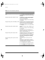
Table 3-3 describes SNMP conÞguration commands.
Table 3-3: SNMP Configuration Commands
Command
Description
config vlan <name> ipaddress <ip_address>
{<mask>}
Configures an IP address for the VLAN.
This is required in order to use an SNMP
manager.
config iproute add default <ip_address> {<mask>}
{<metric>}
Configures the default gateway for the
switch. A default gateway must be on a
configured IP interface.
enable snmp access
Turns on SNMP support for the Switch.
enable snmp trap
Turns on SNMP trap support.
config snmp add <ipaddress>
Adds the IP address of an SNMP
management station to the access list. Up
to six addresses can be specified.
config snmp add trapreceiver <ipaddress>
{community <string>}
Adds the IP address of a specified trap
receiver. A maximum of six trap receivers
is allowed.
config snmp community [read | readwrite] <string>
Configures the SNMP read and write
community strings. The community string
can have a maximum of 127 characters.
3-12
SUMMIT SWITCH INSTALLATION
AND
USER GUIDE
SUMMIT.BK Page 13 Thursday, September 25, 1997 12:33 PM
USING SNMP
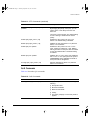
Table 3-3: SNMP Configuration Commands (continued)
Command
Description
config snmp delete [<ipaddress> | all]
Deletes the IP address of a specified
SNMP management station or all SNMP
management stations.
config snmp delete trapreceiver [<ip_address>
community <string> | all]
Deletes the IP address of a specified trap
receiver or all authorized trap receivers. If
you delete all trap receiver addresses,
any machine can have SNMP
management access to the Switch.
config snmp syscontact <string>
Configures the name of the system
contact. A maximum of 255 characters is
allowed.
config snmp sysname <string>
Configures the name of the Switch. A
maximum of 255 characters is allowed.
The default sysname is Summit. The
system name in the Summit prompt.
config snmp syslocation <string>
Configures the location of the Switch. A
maximum of 255 characters is allowed.
DISPLAYING SNMP SETTINGS
To display the SNMP settings conÞgured on the Summit, enter the following command:
show management
This command displays the following information:
¥ Enable/disable state for telnet, SNMP, and Web access
¥ SNMP community strings
¥ Authorized SNMP station list
¥ SNMP trap receiver list
¥ Login statistics
SUMMIT SWITCH INSTALLATION
AND
USER GUIDE
3-13
SUMMIT.BK Page 14 Thursday, September 25, 1997 12:33 PM
ACCESSING THE SWITCH
RESETTING AND DISABLING SNMP
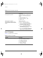
To reset and disable SNMP settings, use the commands in Table 3-4.
Table 3-4: SNMP Reset and Disable Commands
Command
Description
disable snmp access
Disables SNMP on the Switch.
disable snmp trap
Prevents SNMP traps from being sent from the Switch.
Does not clear the SNMP trap receivers that have
been configured.
unconfig management
Restores default values to all SNMP-related entries.
CHECKING BASIC CONNECTIVITY
The Summit offers the following two commands for checking basic connectivity:
¥ ping
¥ traceroute
PING
The ping command enables you to send Internet Control Message Protocol (ICMP) echo
messages to a remote IP device. The ping command is available for both the user and
administrator privilege level.
The ping command syntax is as follows.
ping {continuous} {size <n>} <ip_address>
Options for the ping command are described in Table 3-5.
Table 3-5: Ping Command Parameters
Parameter
Description
continuous
Specifies ICMP echo messages to be sent continuously.
This option can be interrupted by pressing any key.
size <n>
Specifies the size of the packet.
3-14
SUMMIT SWITCH INSTALLATION
AND
USER GUIDE
SUMMIT.BK Page 15 Thursday, September 25, 1997 12:33 PM
CONFIGURING PORTS
TRACEROUTE
The traceroute command enables you to trace the routed path between the Switch and
a destination endstation. The traceroute command syntax is as follows:
traceroute <ip_address>
where the ip_address is the IP address of the destination endstation.
CONFIGURING PORTS
Ports on the Summit1 and Summit2 can be conÞgured in the following ways:
¥ Enabling and disabling individual ports
¥ ConÞguring the port speed (Summit2 only)
¥ ConÞguring half- or full-duplex mode
¥ Creating load-sharing groups on multiple ports
¥ Changing the Quality or Service (QoS) setting for individual ports
For more information on QoS, refer to Chapter 8.
ENABLING AND DISABLING PORTS
By default, all ports are enabled. To enable or disable one or more ports, use the
following command:
[enable | disable] port <portlist>
For example, to disable ports 3, 5, and 12 through 15 on the Summit2, enter the
following:
disable port 3,5,12-15
Even though a port is disabled, the link remains enabled for diagnostic purposes.
SUMMIT SWITCH INSTALLATION
AND
USER GUIDE
3-15
SUMMIT.BK Page 16 Thursday, September 25, 1997 12:33 PM
ACCESSING THE SWITCH
CONFIGURING PORT SPEED AND DUPLEX SETTING
By default, the Summit is conÞgured to use autonegotiation to determine the port speed
and duplex setting for each port. You can select to manually conÞgure the duplex
setting and the speed of the 10/100 Mbps ports on the Summit2, and you can manually
conÞgure the duplex setting on the Summit1.
Ports 1 through 16 on the Summit2 can connect to either 10Base-T or 100Base-T
networks. By default, the ports autonegotiate port speed. You can also conÞgure each
port for a particular speed (either 10 Mbps or 100 Mbps).
Gigabit Ethernet ports on both the Summit1 and the Summit2 are statically set to 1
Gbps, and their speed cannot be modiÞed.
All ports on the Summit1 and Summit2 can be conÞgured for half-duplex or full-duplex
operation. By default, the ports autonegotiate the duplex setting.
To conÞgure port speed and duplex setting, use the following command:
config port <portlist> auto off {speed [10 | 100]} duplex [half |
full]
To conÞgure the Switch to autonegotiate, use the following command:
config port <portlist> auto on
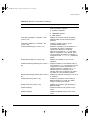
PORT COMMANDS
Table 3-6 describes the port commands.
Table 3-6: Port Commands
Command
Description
config port <portlist> auto on
Enables autonegotiation for the particular port
type; 802.3u for 10/100 Mbps ports or 802.3z for
Gigabit Ethernet ports.
3-16
SUMMIT SWITCH INSTALLATION
AND
USER GUIDE
SUMMIT.BK Page 17 Thursday, September 25, 1997 12:33 PM
PORT COMMANDS
Table 3-6: Port Commands (continued)
Command
Description
config port <portlist> auto off {speed [10 |
100]} duplex [half | full]
Changes the configuration of a group of ports.
Specify the following:
config port <portlist> qosprofile <qosname>
■
auto off — the port will not autonegotiate
the settings
■
speed — the speed of the port (for 10/100
Mbps ports on the Summit2, only)
■
duplex — the duplex setting (half- or
full-duplex)
Configures one or more ports to use a particular
QoS profile.
For more information on QoS, refer to Chapter 8.
enable port <portlist>
Enables a port.
disable port <portlist>
Disables a port. Even when disabled, the link is
available for diagnostic purposes.
enable smartredundancy <portlist>
Enables the smart redundancy feature on the
Summit2 redundant Gigabit Ethernet port. When
the smart redundnacy feature is enabled, the
Switch alway uses the primary link when the
primary link is available.
disable smartredundancy <portlist>
Disables the smart redundancy feature on the
Summit2. If the feature is disabled, the Switch
changes the active link only when the current
active link becomes inoperable.
show port <portlist> config
Displays the port configuration.
show port <portlist> stats
Displays real-time port statistics. For more
information on port statistics, refer to Chapter 10.
show port <portlist> errors
Displays real-time error statistics. For more
information on error statistics, refer to
Chapter 10.
show port <portlist> collisions
Displays real-time collision statistics.
show port <portlist> packet
Displays a histogram of packet statistics.
SUMMIT SWITCH INSTALLATION
AND
USER GUIDE
3-17
SUMMIT.BK Page 18 Thursday, September 25, 1997 12:33 PM
ACCESSING THE SWITCH
3-18
SUMMIT SWITCH INSTALLATION
AND
USER GUIDE
SUMMIT.BK Page 1 Thursday, September 25, 1997 12:33 PM
4
Commands
This chapter contains a description of each command-line interface command for the
Summit. It also provides the following information related to Summit commands:
¥ Command syntax
¥ Line-editing commands
¥ Command history substitution
In order for configuration changes to be retained through a Switch power cycle or
reboot, you must issue a SAVE command after you have made the change. For
more information on the SAVE command, refer to Chapter 11.
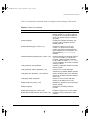
UNDERSTANDING THE COMMAND SYNTAX
This section describes the steps to take when entering a command. Refer to the sections
that follow for detailed information on using the command-line interface.
To use the command-line interface, follow these steps:
1 When entering a command at the prompt, ensure that you have the appropriate
privilege level.
Most conÞguration commands require you to have the administrator privilege level.
2 Enter the command name.
If the command does not include a parameter or values, skip to Step 3. If the
command requires more information, or if you want to include optional arguments,
continue to Step 2a.
SUMMIT SWITCH INSTALLATION
AND
USER GUIDE
4-1
SUMMIT.BK Page 2 Thursday, September 25, 1997 12:33 PM
COMMANDS
a If the command has additional options, include them after the command name.
b If the command includes a parameter, enter the parameter name and values.
The value part of the command speciÞes how you want the parameter to be set.
Values include numerics, strings, or addresses, depending on the parameter.
3 After entering the complete command, press [Return].
If an asterisk (*) appears in front of the command-line prompt, it indicates that
you have outstanding configuration changes that have not been saved. For more
information on saving configuration changes, refer to Chapter 11.
SYNTAX HELPER
The command-line interface has a built-in syntax helper. If you are unsure of the
complete syntax for a particular command, enter as much of the command as possible.
The syntax helper provides a list of options for the remainder of the command.
The syntax helper also provides assistance if you have entered an incorrect command.
COMMAND COMPLETION
The Summit provides command completion by way of the [Tab] key. If you enter the
beginning of a unique command, pressing [Tab] forces the Summit to Þll in the
remainder of the command.
ABBREVIATED SYNTAX
Abbreviated syntax is the shortest, most unambiguous, allowable abbreviation of a
command, parameter, or value. Typically, this is the Þrst three letters of the command.
COMMAND SHORTCUTS
All named components of the Switch conÞguration must have a unique name.
Components are named using the create command. When you enter a command to
conÞgure a named component, you do not need to use the keyword of the component.
For example, to create a VLAN, you must enter a unique VLAN name:
create vlan engineering
4-2
SUMMIT SWITCH INSTALLATION
AND
USER GUIDE
SUMMIT.BK Page 3 Thursday, September 25, 1997 12:33 PM
UNDERSTANDING
THE
COMMAND SYNTAX
Once you have created the VLAN with a unique name, you can then eliminate the
keyword vlan from all other commands that require the name to be entered. For
example, instead of entering the command
config vlan engineering add port 1-3,6
you could enter the following shortcut:
config engineering add port 1-3, 6
NUMERICAL RANGES
Commands that require you to enter one or more port numbers use the parameter
<portlist> in the syntax. A portlist can be a range of numbers, for example:
port 1-3
You can add additional port numbers to the list, separated by a comma:
port 1-3,6,8
NAMES
All named components of the Switch conÞguration must have a unique name. Names
must begin with an alphabetical character delimited by whitespace, unless enclosed in
quotation marks.
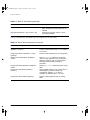
SYMBOLS
You may see a variety of symbols shown as part of the command syntax. These symbols
explain how to enter the command, and you do not type them as part of the command
itself. Table 4-1 summarizes command syntax symbols.
Table 4-1: Command Syntax Symbols
Symbol
Description
angle brackets < >
Enclose a variable or value. You must specify the variable or value. For
example, in the syntax
config vlan <name> ipaddress <ip_address>
you must supply a VLAN name for <name> and an address for
<ip_address> when entering the command. Do not type the angle
brackets.
SUMMIT SWITCH INSTALLATION
AND
USER GUIDE
4-3
SUMMIT.BK Page 4 Thursday, September 25, 1997 12:33 PM
COMMANDS
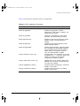
Table 4-1: Command Syntax Symbols (continued)
Symbol
Description
square brackets [ ]
Enclose a required value or list of required arguments. One or more
values or arguments can be specified. For example, in the syntax
disable vlan [<name> | all]
you must specify either the VLAN name for <name>, or the keyword all
when entering the command. Do not type the square brackets.
vertical bar |
Separates mutually exclusive items in a list, one of which must be
entered. For example, in the syntax
config snmp community [read | write] <string>
you must specify either the read or write community string in the
command. Do not type the vertical bar.
braces { }
Enclose an optional value or a list of optional arguments. One or more
values or arguments can be specified. For example, in the syntax
show vlan {<name> | all}
you can specify either a particular VLAN or the keyword all. If you do
not specify an argument, the command will show all VLANs. Do not type
the braces.
LINE-EDITING KEYS
Table 4-2 describes the line-editing keys available using the command-line interface.
Table 4-2: Line-Editing Keys
Key(s)
Description
Backspace
Deletes character to the left of cursor and shifts remainder of line to left.
Delete or [Ctrl]+D
Deletes character under cursor and shifts remainder of line to left.
[Ctrl] + K
Deletes characters from under cursor to the end of the line.
Insert
Toggles on and off. When toggled on, inserts text and pushes previous
text to right.
Left Arrow
Moves cursor to left.
Right Arrow
Moves cursor to right.
Home or [Ctrl]+A
Moves cursor to first character in line.
End or [Ctrl]+E
Moves cursor to last character in line.
[Ctrl]+L
Clears the screen and movers the cursor to the beginning of the line.
4-4
SUMMIT SWITCH INSTALLATION
AND
USER GUIDE
SUMMIT.BK Page 5 Thursday, September 25, 1997 12:33 PM
COMMAND HISTORY
Table 4-2: Line-Editing Keys (continued)
Key(s)
Description
Up Arrow
Displays the previous command in the command history buffer, and
places cursor at end of command.
Down Arrow
Displays the next command in the command history buffer, and places
cursor at end of command.
COMMAND HISTORY
The Summit ÒremembersÓ the last 50 commands you enter. You can display a list of
these commands by using the following command:
history
COMMON COMMANDS
Table 4-3 describes common commands used to manage the Switch. Commands
speciÞc to a particular feature are described in the other chapters of this guide.
Table 4-3: Common Commands
Command
Description
create account [admin | user] <username>
{<password>}
Creates a user account. For more
information on creating accounts, refer to
Chapter 3.
create vlan <name>
Creates a VLAN. For more information on
VLANs, refer to Chapter 5.
config account <username> {<password>}
Configures a user account password.
SUMMIT SWITCH INSTALLATION
AND
USER GUIDE
4-5
SUMMIT.BK Page 6 Thursday, September 25, 1997 12:33 PM
COMMANDS
Table 4-3: Common Commands (continued)
Command
Description
config devicemode [bridging | iprouting | ipmc ]
Configures the operating mode of the
Switch. Specify:
■
bridging — Layer 2 bridging
functions only
■
iprouting — Bridging and IP unicast
routing functions
■
ipmc — Bridging, IP unicast routing,
and IP multicast routing functions
If this command is used to change the
operating mode of the Summit once it is
up and running, it causes the Switch to
save the configuration and reboot. The
default operating mode is iprouting.
config port <portlist> auto off {speed [10 | 100]}
duplex [half | full]
Manually configures the port speed and
duplex setting of one or more ports. For
more information on configuring ports,
refer to Chapter 3.
config time <time>
Configures the system date and time. The
format for <time> is:
mm/dd/yyyy hh:mm:ss
The time uses a 24-hour clock format.
config vlan <name> ipaddress <ip_address>
{<mask>}
Configures an IP address and subnet
mask for a VLAN.
enable bootp vlan [<name> | all]
Enables BOOTP for one or more VLANs.
For more information on using BOOTP,
refer to Chapter 3.
clear session <number>
Terminates a Telnet session from the
Switch.
disable bootp vlan [<name> | all]
Disables BOOTP for one or more VLANs.
disable port <portlist>
Disables a port.
disable telnet
Disables Telnet access to the Switch.
disable web
Disables web access to the Switch.
delete account <username>
Deletes a user account.
delete vlan <name>
Deletes a VLAN.
4-6
SUMMIT SWITCH INSTALLATION
AND
USER GUIDE
SUMMIT.BK Page 7 Thursday, September 25, 1997 12:33 PM
SUMMIT COMMANDS
Table 4-3: Common Commands (continued)
Command
Description
unconfig switch {all}
Resets all switch parameters (with the
exception of defined user accounts) to the
factory defaults. If you specify the keyword
all, the user account information is reset
as well.
SUMMIT COMMANDS
The tables in this section list all of the commands used on the Summit Switch. The
commands are organized by the following categories:
¥ General Switch commands
¥ User account commands
¥ Switch management commands
¥ VLAN commands
¥ Protocol commands
¥ FDB commands
¥ Port commands
¥ STP commands
¥ QoS commands
¥ Basic IP commands
¥ IP ARP commands
¥ IP Route Table commands
¥ ICMP commands
¥ RIP commands
¥ Logging commands
¥ ConÞguration and image commands
SUMMIT SWITCH INSTALLATION
AND
USER GUIDE
4-7
SUMMIT.BK Page 8 Thursday, September 25, 1997 12:33 PM
COMMANDS
GENERAL SWITCH COMMANDS
Table 4-4 describes general Switch commands.
Table 4-4: General Switch Commands
Command
Description
show switch
Displays the current Switch information,
including:
■
sysName, sysLocation, sysContact
■
MAC address
■
Current date and time, and system uptime
■
Operating environment (temperature, fans,
and power supply status)
■
Nonvolatile Random Access Memory
(NVRAM) image information
(primary/secondary image, date, time, size,
version)
■
NVRAM configuration information
(primary/secondary configuration, date,
time, size, version)
■
Scheduled reboot information
■
System serial number and reworks indicator
■
Software platform
■
System ID
■
Power supply and fan status
show version
Displays the hardware and software versions
currently running on the Switch. Also displays
the Switch serial number.
show memory
Displays the current system memory
information.
reboot {<time>}
Reboots the Switch at the time specified. If no
time is specified, the Switch reboots
immediately following the command.
config time <time>
Configures the system date and time. The
format for <time> is:
mm/dd/yyyy hh:mm:ss
The time uses a 24-hour clock format.
4-8
SUMMIT SWITCH INSTALLATION
AND
USER GUIDE
SUMMIT.BK Page 9 Thursday, September 25, 1997 12:33 PM
SUMMIT COMMANDS
Table 4-4: General Switch Commands (continued)
Command
Description
config devicemode [bridging | iprouting ]
Configures the operating mode of the Switch.
Specify:
■
bridging — Layer 2 bridging functions only
■
iprouting — Bridging and IP unicast
routing functions
If this command is used to change the
operating mode of the Summit once it is up
and running, it causes the Switch to save the
configuration and reboot. The default
operating mode is iprouting.
unconfig switch {all}
Resets all Switch parameters (with the
exception of defined VLANs and IP
addresses) to the factory defaults. If you
specify the keyword all, the IP addresses are
reset as well.
ping {continuous} {size <number>} <ipaddress> Sends ICMP echo messages to a remote IP
device. Specify:
■
continuous — ICMP echo messages
should be sent continuously.
■
size <n> — The size of the packet.
The continuous option can be interrupted by
pressing any key.
traceroute <ipaddress>
Traces the routed path between the Switch
and a destination endstation.
clear counters
Clears all statistical counters for the Switch
and ports.
USER ACCOUNT COMMANDS
Table 4-5 describes user account commands.
SUMMIT SWITCH INSTALLATION
AND
USER GUIDE
4-9
SUMMIT.BK Page 10 Thursday, September 25, 1997 12:33 PM
COMMANDS
Table 4-5: User Account Commands
Command
Description
show account
Displays the account names, access level,
number of successful and failed login attempts,
and the number of active sessions in the user
database. This command is available only to
admin level users.
create account [admin | user] <username>
{<password>}
Creates a user account.
delete account <username>
Deletes a user account
config account <username> {<password>}
Changes the password of an existing account.
SWITCH MANAGEMENT COMMANDS
Table 4-6 describes Switch management commands.
Table 4-6: Switch Management Commands
Command
Description
show management
Displays network management configuration
and statistics, including enable/disable states
for Telnet and SNMP, SNMP community
strings, authorized SNMP station list, SNMP
trap receiver list, and login statistics.
show session
Displays the currently active Telnet and
console sessions communicating with the
Switch. Provides the user name, IP address of
the incoming Telnet session, whether a
console session is currently active, and login
time. Sessions are numbered.
clear session <number>
Terminates a Telnet session from the Switch.
logout | quit
Logs out of a console or Telnet session. If
used during a Telnet session, also closes the
TCP Telnet session.
enable telnet
Enables Telnet access to the Switch.
disable telnet
Disables Telnet access to the Switch.
enable web
Enables web access to the Switch. Requires a
reboot to take effect.
4-10
SUMMIT SWITCH INSTALLATION
AND
USER GUIDE
SUMMIT.BK Page 11 Thursday, September 25, 1997 12:33 PM
SUMMIT COMMANDS
Table 4-6: Switch Management Commands (continued)
Command
Description
disable web
Disables web access to the Switch. Requires
a reboot to take effect.
enable snmp access
Turns on SNMP support for the Switch.
disable snmp access
Disables SNMP on the Switch.
enable snmp trap
Turns on SNMP trap support.
disable snmp trap
Prevents SNMP traps from being sent from
the Switch. Does not clear the SNMP trap
receivers that have been configured.
config snmp add <ipaddress>
Adds the IP address of an SNMP management
station to the access list. Up to six addresses
can be specified.
config snmp delete [<ipaddress | all]
Deletes the IP address of a specified SNMP
management station or all SNMP
management stations.
config snmp add trapreceiver <ipaddress>
{<comm_string>}
Adds the IP address of a specified trap
receiver. A maximum of six trap receivers is
allowed.
config snmp delete trapreceiver [<ip_address>
community <string> | all]
Deletes the IP address of a specified trap
receiver or all authorized trap receivers. If you
delete all trap receiver addresses, any machine
can have SNMP management access to the
Switch.
config snmp community [read | readwrite]
<string>
Configures the SNMP read and write
community strings. The community string can
have a maximum of 127 characters.
config snmp syscontact <string>
Configures the name of the system contact. A
maximum of 255 characters is allowed
config snmp sysname <string>
Configures the name of the Switch. The
sysname appears in the command-line
interface prompt. A maximum of 255
characters is allowed. The default sysname is
Summit1 or Summit2.
config snmp syslocation <string>
Configures the location of the Switch. A
maximum of 255 characters is allowed.
unconfig management
Restores default values to all SNMP-related
entries.
SUMMIT SWITCH INSTALLATION
AND
USER GUIDE
4-11
SUMMIT.BK Page 12 Thursday, September 25, 1997 12:33 PM
COMMANDS
VLAN COMMANDS
Table 4-7 describes VLAN commands.
Table 4-7: VLAN Commands
Command
Description
show vlan {<name> | all>
When used with the keyword all, or with no
named VLANs, displays a summary list of
VLAN names with a portlist and associated
status of each. When used with a named
identifier, displays port information, including
membership list, IP address, and tag
information.
create vlan <name>
Creates a named VLAN.
delete vlan <name>
Removes a VLAN.
config vlan <name> [add | delete] port
<portlist> {tagged | untagged}
Adds and deletes ports. You can specify
tagged and untagged port(s). By default, ports
are untagged.
config vlan <name> tag <vlanid>
Assigns a numerical VLANid. The valid range
is from 1 to 4095.
config vlan <name> protocol
[<protocol_name> | any]
Configures a protocol-based VLAN. If the
keyword any is specified, then it becomes the
default VLAN. All packets that cannot be
classified into other protocol-based VLANs are
assigned to the default VLAN of that port.
config vlan <name> qosprofile <qosname>
Configures a VLAN to use a particular QoS
profile. Dynamic FDB entries associated with
the VLAN are flushed once this change is
committed.
config vlan <name> ipaddress <ipaddress>
{<mask>}
Assigns an IP address and an optional mask to
the VLAN.
config dot1q ethertype <ethertype>
Configures an IEEE 802.1Q Ethertype. Use
this command if you have another Switch that
supports 802.1Q, but uses a different
Ethertype. The default value used by the
Switch is 8100.
unconfig vlan <name> ipaddress
Removes the IP address associated with a
VLAN.
4-12
SUMMIT SWITCH INSTALLATION
AND
USER GUIDE
SUMMIT.BK Page 13 Thursday, September 25, 1997 12:33 PM
SUMMIT COMMANDS
PROTOCOL COMMANDS
Table 4-8 describes protocol commands.
Table 4-8: Protocol Commands
Command
Description
show protocol {<protocol_name> | all}
Displays protocol-related information, including:
■
Protocol name
■
List of protocol fields
■
List of VLANs that use this protocol
create protocol <protocol _ name>
Creates a user-defined protocol.
delete protocol <protocol_name>
Removes a protocol.
config protocol <protocol_name> [add |
delete] <prototype_number>
{<prototype_number>} ...
Configures a protocol filter. Supported protocol
types include:
■
EtherType
■
LLC
■
SNAP
FDB COMMANDS
Table 4-9 describes FDB commands.
Table 4-9: FDB Commands
Command
Description
show fdb {all | <mac_address> | vlan <name> | Displays the forwarding database contents
<portlist> | permanent}
including MAC address, associated VLAN,
port, age-of-entry configuration method, and
status. Providing one of the options acts as a
filter on the display. Providing a VLAN name
displays all entries for the VLAN. Use the MAC
address to locate a specific entry in the FDB.
clear fdb {all | <mac_address> | vlan <name>
| <portlist> }
SUMMIT SWITCH INSTALLATION
AND
USER GUIDE
Clears dynamic FDB entries that match the
filter. Use the keyword all to clear all dynamic
entries.
4-13
SUMMIT.BK Page 14 Thursday, September 25, 1997 12:33 PM
COMMANDS
Table 4-9: FDB Commands (continued)
Command
Description
create fdbentry <mac_address> vlan <name>
<portlist>
Creates a permanent FDB entry. Specify the
following:
■
mac_address — Device MAC address,
using colon-separated bytes.
■
name — VLAN associated with MAC
address.
■
portlist — Port number associated with
MAC address.
If more than one port number is associated
with a permanent MAC entry, packets are
multicast to the multiple destinations.
delete fdbentry <mac_address> vlan <name>
Deletes a permanent FDB entry.
config fdb agingtime <number>
Configures the FDB aging time. The range is
15 through 1,000,000 seconds. The default
value is 1,800 seconds. A value of 0 indicates
that the entry should never be aged out.
PORT COMMANDS
Table 4-10 describes port commands.
Table 4-10: Port Commands
Command
Description
show port <portlist> config
Displays state, link status, speed, and
autonegotiation setting for each port.
show port <portlist> stats
Displays port information including physical
layer configuration and statistics.
show port <portlist> errors
Displays error information for one or more
ports.
show port <portlist> collisions
Displays real-time collision statistics.
show port <portlist> packet
Displays a histogram of packet statistics for
one or more ports.
config port <portlist> auto on
enables autonegotiation for the particular port
type: 802.3u for 10/100 Mbps ports or 802.3z
for Gigabit Ethernet ports.
4-14
SUMMIT SWITCH INSTALLATION
AND
USER GUIDE
SUMMIT.BK Page 15 Thursday, September 25, 1997 12:33 PM
SUMMIT COMMANDS
Table 4-10: Port Commands
Command
Description
config port <portlist> auto off {speed [10 | 100]} Changes the configuration of a group of ports.
duplex [half | full]
Specify the following:
■
auto off — The port will not autonegotiate
the settings.
■
speed — The speed of the port (for 10/100
Mbps ports on the Summit2, only.
■
duplex — The duplex setting (half- or
full-duplex).
config port <portlist> qosprofile <qosname>
Configures one or more ports to use a
particular QoS profile.
enable port <portlist>
Enables one or more ports.
disable port <portlist>
Disables one or more ports.
enable smartredundancy <portlist>
Enables smart redundancy on the Summit2
redundant Gigabit Ethernet port.
disable smartredundancy <portlist>
Disables smart redundancy on the Summit2.
STP COMMANDS
Table 4-11 describes STP commands.
Table 4-11: STP Commands
Command
Description
show stpd {<stpd_name> | all}
Displays STP information for one or all STPDs
on the Switch.
show stpd <stpd_name> port <portlist>
Displays port-specific STP information.
create stpd <stpd_name>
Creates an STPD. When created, an STPD
has the following default parameters:
■
Bridge priority — 32,768
■
Hello time — 2 seconds
■
Forward delay — 15 seconds
delete stpd <stpd_name>
Removes an STPD. An STPD can only be
removed if all VLANs have been deleted from
it.
config stpd <stpd_name> add vlan <name>
Adds a VLAN to the STPD.
SUMMIT SWITCH INSTALLATION
AND
USER GUIDE
4-15
SUMMIT.BK Page 16 Thursday, September 25, 1997 12:33 PM
COMMANDS
Table 4-11: STP Commands (continued)
Command
Description
config stpd <stpd_name> delete vlan [<name>
| all]
Removes one or all VLANs from an STPD. If
all is specified, the association between the
STPD and VLAN is removed, but both are still
instantiated.
config stpd <stpd_name> hellotime <value>
Specifies the time delay (in seconds) between
the transmission of BPDUs from this STPD
when it is the Root Bridge.
The range is 1 through 10. The default setting
is 2 seconds.
config stpd <stpd_name> forwarddelay <value> Specifies the time (in seconds) that the ports in
this STPD spend in the listening and learning
states when the Switch is the Root Bridge.
The range is 4 through 30. The default setting
is 15 seconds.
config stpd <stpd_name> maxage <value>
Specifies the maximum age of a BPDU in this
STPD.
The range is 6 through 40. The default setting
is 20 seconds.
Note that the time must be greater than, or
equal to 2 X (Hello Time + 1) and less than, or
equal to 2 X (Forward Delay –1).
config stpd <stpd_name> priority <value>
Specifies the priority of the STPD. By changing
the priority of the STPD, you can make it
more or less likely to become the Root Bridge.
The range is 0 through 65,535. The default
setting is 32,768. A setting of 0 indicates the
highest priority.
config stpd <stpd_name> port cost <value>
<portlist>
Specifies the path cost of the port in this
STPD.
The range is 1 through 65,535. The Switch
automatically assigns a default path cost based
on the speed of the port, as follows:
4-16
■
For a 10Mbps port, the default cost is 100.
■
For a 100Mbps port, the default cost is 19.
■
For a 1000Mbps port, the default cost is 4.
SUMMIT SWITCH INSTALLATION
AND
USER GUIDE
SUMMIT.BK Page 17 Thursday, September 25, 1997 12:33 PM
SUMMIT COMMANDS
Table 4-11: STP Commands (continued)
Command
Description
config stpd <stpd_name> port priority <value>
<portlist>
Specifies the priority of the port in this STPD.
By changing the priority of the port, you can
make it more or less likely to become the
Root Port.
The range is 0 through 255. The default setting
is 128. A setting of 0 indicates the lowest
priority.
enable stpd [<stpd_name> | all]
Enables the STP protocol for one or all
STPDs. The default setting is disabled.
disable stpd [<stpd_name> | all]
Disables the STP mechanism on a particular
STPD, or for all STPDs.
enable stpd port <portlist>
Enables the STP protocol on one or more
ports. If STPD is enabled for a port, BPDUs
will be generated on that port if STP is enabled
for the associated STPD. The default setting
is enabled.
disable stpd port <portlist>
Disables STP on one or more ports. Disabling
STP on one or more ports puts those ports in
FORWARDING state; all BPDUs received on
those ports will be disregarded.
unconfig stpd {<stpd_name> | all}
Restores default STP values to a particular
STPD or to all STPDs.
QOS COMMANDS
Table 4-12 describes QoS commands.
Table 4-12: QoS Commands
Command
Description
show qosprofile {<qosname> | all}
Displays QoS profile information, including the
following:
SUMMIT SWITCH INSTALLATION
AND
USER GUIDE
■
QoS profile name
■
Minimum bandwidth
■
Maximum bandwidth
■
Priority
■
The traffic groupings to which this profile is
applied.
4-17
SUMMIT.BK Page 18 Thursday, September 25, 1997 12:33 PM
COMMANDS
Table 4-12: QoS Commands (continued)
Command
Description
config qosmode [explicit | implicit]
Changes the QoS mode to explicit mode or
implicit mode.
create qosprofile <qosname>
Creates a QoS profile. The default values
assigned to a created QoS profile are as
follows:
■
Minimum bandwidth — 0%
■
Maximum bandwidth — 100%
■
Priority — low
delete qosprofile <qosname>
Deletes a QoS profile.
config qosprofile <qosname> {minbw
<percent>} {maxbw <percent>} {priority
<level>}
Configures a QoS profile. Specify:
■
minbw — The minimum bandwidth
percentage guaranteed to be available to
this queue. The default setting is 0.
■
maxbw — The maximum bandwidth
percentage that this queue is permitted to
use. The default setting is 100.
■
priority — The service priority for this
queue. Settings include low, medium-low,
medium, high. The default setting is low.
BASIC IP COMMANDS
Table 4-13 describes basic IP commands.
Table 4-13: Basic IP Commands
Command
Description
show ip config {vlan [<name> | all]}
Displays configuration information for one or
more VLANs, including the following:
4-18
■
IP address, subnet mask
■
IP forwarding information
■
BOOTP configuration
■
VLAN name, VLANid
SUMMIT SWITCH INSTALLATION
AND
USER GUIDE
SUMMIT.BK Page 19 Thursday, September 25, 1997 12:33 PM
SUMMIT COMMANDS
Table 4-13: Basic IP Commands (continued)
Command
Description
show ip stats {vlan [<name | all]}
Displays statistics of packets handled by the
CPU, including the following:
■
inpackets, outpackets
■
ICMP/IGMP statistics
■
IRDP statistics
show ipfdb {<ipaddress> <netmask> | vlan
<name> | all}
Displays the contents of the IP forwarding
database table. Use for technical support
purposes.
clear ipfdb [<ipaddress> <netmask> | vlan
<name> | all]
Clears the dynamic entries in the IP
forwarding database table.
enable ipforwarding {vlan <name> | all}
Enables IP forwarding to an IP interface. If all
is specified, then all the configured IP
interfaces are affected. If no optional
argument is provided, the all is assumed.
Other IP configuration is not affected. When
new IP interfaces are added, the interface is
configured to have ipforwarding disabled by
default.
disable ipforwarding {vlan <name> | all}
Disables IP forwarding on one or all IP
interfaces.
enable ipforwarding broadcast {vlan <name> |
all}
Enables forwarding of IP broadcast traffic on
an IP interface. If all is specified, then all the
configured IP interfaces are affected. If no
optional argument is provided, then all is
assumed. Other IP configuration is not
affected. When new IP interfaces are added,
the default is to have broadcast enabled.
disable ipforwarding broadcast {vlan <name> |
all}
Disables IP broadcast forwarding on one or all
IP interfaces.
enable bootp vlan [<name> | all]
Enables the generation and processing of
BOOTP packets on a VLAN. The default
setting is enabled for all VLANs.
disable bootp vlan [<name> | all]
Disables the generation and processing of
BOOTP packets.
enable bootprelay
Enables the BOOTP relay function on the
router.
disable bootprelay
Disables the BOOTP relay function on the
router.
SUMMIT SWITCH INSTALLATION
AND
USER GUIDE
4-19
SUMMIT.BK Page 20 Thursday, September 25, 1997 12:33 PM
COMMANDS
Table 4-13: Basic IP Commands (continued)
Command
Description
config bootprelay add <ipaddress>
Adds IP addresses to be used as IP
destinations to forward BOOTP packets.
config bootprelay delete [<ipaddress> | all]
Deletes one or all IP addresses that were used
as IP destinations to forward BOOTP packets.
show iparp {<ipaddress> | vlan <name> | all |
permanent}
Displays the current Address Resolution
Protocol (ARP) cache for a selected IP
address, VLAN, or all entries. With no options,
information for all VLANs is displayed.
Information displayed includes IP address,
MAC address, aging timer value, VLAN name,
VLANid, and port number.
clear iparp [<ipaddress> | vlan <name> | all]
Removes dynamic entries in the IP ARP table.
show iproute vlan {<name> | all | permanent}
Displays the contents of the IP routing table.
config iproute add default <gateway>
{<metric>}
Adds a default gateway. A default gateway
must be located on a configured IP interface.
config iproute delete default <gateway>
Deletes a default gateway.
IP ARP COMMANDS
Table 4-14 describes IP ARP commands.
Table 4-14: IP ARP Commands
Command
Description
show iparp {<ipaddress> | vlan <name> | all |
permanent}
Displays the current Address Resolution
Protocol (ARP) cache for a selected IP
address, VLAN, or all entries. With no options,
information for all VLANs is displayed.
Information displayed includes IP address,
MAC address, aging timer value, VLAN name,
VLANid, and port number.
clear iparp [<ipaddress> | vlan <name> | all]
Removes dynamic entries in the IP ARP table.
config iparp add <ipaddress> <mac_address>
Adds a permanent IP ARP entry to the system.
The IP address is used to match the IP
interface address to locate a suitable interface.
config iparp delete <ipaddress>
Removes an IP ARP entry from the table.
show iproute vlan {<name> | all | permanent}
Displays the contents of the IP routing table.
4-20
SUMMIT SWITCH INSTALLATION
AND
USER GUIDE
SUMMIT.BK Page 21 Thursday, September 25, 1997 12:33 PM
SUMMIT COMMANDS
Table 4-14: IP ARP Commands (continued)
Command
Description
config iproute add default <gateway>
{<metric>}
Adds a default gateway. A default gateway
must be located on a configured IP interface.
config iproute delete default <gateway>
Deletes a default gateway.
IP ROUTE TABLE COMMANDS
Table 4-15 describes IP Route Table commands.
Table 4-15: IP Route Table Commands
Command
Description
show iproute vlan {<name> | all | permanent |
<ipaddress> <netmask>}
Displays the contents of the IP routing table.
config iproute add default <gateway>
{<metric>}
Adds a default gateway to the routing table. A
default gateway must be located on a
configured IP interface . If no metric is
specified, the default metric of 1 is used.
config iproute delete default <gateway>
Deletes a default gateway.
config iproute add <ipaddress> <mask>
<gateway> {<metric>}
Adds a static address to the routing table. Use
a value of 255.255.255.255 for mask to indicate
a host entry.
config iproute delete <ipaddress> <mask>
<gateway>
Deletes a static address from the routing table.
config iproute add blackhole <ipaddress>
<mask>
Adds a blackhole address to the routing
table. All traffic destined for the configured IP
address is dropped, and no Internet Control
Message Protocol (ICMP) message is
generated.
config iproute delete blackhole <ipaddress>
<mask>
Deletes a blackhole address from the routing
table.
SUMMIT SWITCH INSTALLATION
AND
USER GUIDE
4-21
SUMMIT.BK Page 22 Thursday, September 25, 1997 12:33 PM
COMMANDS
ICMP COMMANDS
Table 4-16 describes the commands used to conÞgure the ICMP protocol.
Table 4-16: ICMP Commands
Command
Description
enable icmp redirects {vlan <name> | all}
Enables generation of ICMP redirect messages
on one or more VLANs. The default setting is
enabled.
disable icmp redirects {vlan <name> | all}
Disables the generation of ICMP redirects on
one or more VLANs.
enable icmp unreachables {vlan <name> | all}
Enables the generation of ICMP unreachable
messages on one or more VLANs. The default
setting is enabled.
disable icmp unreachables
Disables the generation of ICMP unreachable
messages on one or more VLANs.
enable icmp useredirects
Enables the modification of route table
information when an ICMP redirect message
is received. The default setting is disabled.
disable icmp useredirects
Disables the changing of routing table
information when an ICMP redirect message
is received.
enable irdp {vlan <name> | all}
Enables the generation of ICMP router
advertisement messages on one or more
VLANs. The default setting is enabled.
disable irdp {vlan <name> | all}
Disables the generation of router
advertisement messages on one or more
VLANs.
config irdp [multicast | broadcast]
Configures the destination address of the
router advertisement messages. The default
setting is broadcast.
4-22
SUMMIT SWITCH INSTALLATION
AND
USER GUIDE
SUMMIT.BK Page 23 Thursday, September 25, 1997 12:33 PM
SUMMIT COMMANDS
Table 4-16: ICMP Commands (continued)
Command
Description
config irdp <mininterval> <maxinterval>
<lifetime> <preference>
Configures the router advertisement message
timers, using seconds. Specify:
■
mininterval — The minimum amount of
time between router advertisements. The
default setting is 450 seconds.
■
maxinterval — The maximum time
between router advertisements. The default
setting is 600 seconds.
■
lifetime — The default setting is 1,800
seconds.
■
preference
unconfig icmp
Resets all ICMP settings to the default values.
unconfig irdp
Resets all router advertisement settings to the
default values.
disable irdp {vlan <name> | all}
Disables the generation of router
advertisement messages on one or more
VLANs.
RIP COMMANDS
Table 4-17 describes the commands used to conÞgure the RIP protocol.
Table 4-17: RIP Commands
Command
Description
show rip {vlan <name> | all}
Displays RIP configuration and statistics for
one or more VLANs. Display includes the
state for RIP settings, and interface states.
Statistics include the following:
SUMMIT SWITCH INSTALLATION
AND
USER GUIDE
■
Packets transmitted
■
Packets received
■
Bad packets received
■
Bad routes received
■
Number of RIP peers
■
Peer information
4-23
SUMMIT.BK Page 24 Thursday, September 25, 1997 12:33 PM
COMMANDS
Table 4-17: RIP Commands (continued)
Command
Description
Displays RIP-specific statistics. Statistics
include the following per interface:
■
Packets transmitted
■
Packets received
■
Bad packets received
■
Bad routes received
■
Number of RIP peers
■
Peer information
enable rip
Enables RIP.
disable rip
Disables RIP.
config rip add {vlan <name> | all}
Configures RIP on an IP interface. If no VLAN
is specified, then all is assumed. When an IP
interface is created, per interface RIP
configuration is enabled by default.
config rip delete {vlan <name> | all}
Disables RIP on an IP interface. When RIP is
disabled on the interface, the parameters are
not reset to their defaults.
enable rip aggregation
Enables RIP aggregation of subnet
information on a RIP version 2 interface. The
default setting is enabled.
disable rip aggregation
Disables the RIP aggregation of subnet
information on a RIP version 2 interface.
enable rip splithorizon
Enables the split horizon algorithm for RIP.
Default setting is enabled.
disable rip splithorizon
Disables split horizon.
enable rippoisonreverse
Enables the split horizon with poison-reverse
algorithm for RIP. The default setting is
enabled.
disable rip poisonreverse
Disables poison reverse.
enable rip triggerupdate
Enables triggered updates. Triggered updates
are a mechanism for immediately notifying a
router’s neighbors when the router adds or
deletes routes, or changes the metric of a
route. The default setting is enabled.
disable rip triggerupdate
Disables triggered updates.
enable rip exportstatic
Enables the advertisement of static routes
using RIP. The default setting is enabled.
4-24
SUMMIT SWITCH INSTALLATION
AND
USER GUIDE
SUMMIT.BK Page 25 Thursday, September 25, 1997 12:33 PM
SUMMIT COMMANDS
Table 4-17: RIP Commands (continued)
Command
Description
disable rip exportstatic
Disables the filtering of static routes.
config rip updatetime {<delay>}
Changes the periodic RIP update timer. The
default setting is 30 seconds.
config rip routetimeout {<delay>}
Configures the route timeout. The default
setting is 180 seconds.
config rip garbagetime {<delay>}
Configures the RIP garbage time. The default
setting is 120 seconds.
config rip txmode [none | v1only | v1comp |
v2only] {vlan <name> | all}
Changes the RIP transmission mode for one or
more VLANs. Specify:
■
none — Do not transmit any packets on this
interface.
■
v1only — Transmit RIP version 1 format
packets to the broadcast address.
■
v1comp — Transmit version 2 format
packets to the broadcast address.
■
v2only — Transmit version 2 format
packets to the RIP multicast address.
If no VLAN is specified, the setting is applied
to all VLANs. The default setting is v2only.
config rip rxmode [none | v1only | v2only |
any] {vlan <name> | all}
Changes the RIP receive mode for one or
more VLANs. Specify:
■
none — Drop all received RIP packets.
■
v1only — Accept only RIP version 1 format
packets.
■
v2only — Accept only RIP version 2 format
packets.
■
any — Accept both version 1 and version 2
packets.
If no VLAN is specified, the setting is applied
to all VLANs. The default setting is any.
unconfig rip {vlan <name> | all}
SUMMIT SWITCH INSTALLATION
AND
USER GUIDE
Resets all RIP parameters to the default VLAN.
Does not change the enable/disable state of
the RIP settings.
4-25
SUMMIT.BK Page 26 Thursday, September 25, 1997 12:33 PM
COMMANDS
LOGGING COMMANDS
Table 4-18 describes Switch logging commands.
Table 4-18: Logging Commands
Command
Description
show log config
Displays the log configuration, including the
syslog host IP address, the priority level of
messages being logged locally, and the
priority level of messages being sent to the
syslog host.
show log {<priority>} {<subsystem>}
Displays the current snapshot of the log.
Options include:
■
priority — Filters the log to display
messages with the selected priority or
higher (more critical). Priorities include
critical, warning, and informational. If not
specified, informational priority messages
and higher are displayed.
■
subsystem — Filters the log to display
messages associated with the selected
Switch subsystem. Subsystems include
Syst, STP, Brdg, SNMP, Telnet, VLAN,
and Port. If not specified, all subsystems
are displayed.
clear log
Clears the log.
config log display {<priority>} {<subsystem>}
Configures the real-time log display. Options
include:
4-26
■
priority — Filters the log to display
messages with the selected priority or
higher (more critical). Priorities include
critical, warning, and informational. If not
specified, informational priority messages
and higher are displayed.
■
subsystem — Filters the log to display
messages associated with the selected
Switch subsystem. Subsystems include
Syst, STP Brdg, SNMP, Telnet, VLAN, and
Port. If not specified, all subsystems are
displayed.
SUMMIT SWITCH INSTALLATION
AND
USER GUIDE
SUMMIT.BK Page 27 Thursday, September 25, 1997 12:33 PM
SUMMIT COMMANDS
Table 4-18: Logging Commands (continued)
Command
Description
config syslog <ipaddress> <facility>
{<priority>} {<subsystem>}
Configures the syslog host address and filter
messages sent to the syslog host. Options
include:
■
ipaddress — The IP address of the
syslog host.
■
facility — The syslog facility level for
local use.
■
priority — Filters the log to display
messages with the selected priority or
higher (more critical). Priorities include
critical, warning, and informational. If not
specified, only critical priority messages are
sent to the syslog host.
■
subsystem — Filters the log to display
messages associated with the selected
Switch subsystem. Subsystems include
Syst, STP Brdg, SNMP, Telnet, VLAN, and
Port. If not specified, all subsystems are
sent to the syslog host.
enable log display
Enables the log display.
disable log display
Disables the log display.
enable syslog
Enables logging to a remote syslog host.
disable syslog
Disables logging to a remote syslog host.
CONFIGURATION AND IMAGE COMMANDS
Table 4-19 describes conÞguration and image commands
Table 4-19: Configuration and Image Commands
Command
Description
save {config} {primary | secondary}
Downloads a previously saved ASCII
configuration file from a specific IP host. You
must specify the IP address of the host and
the configuration filename.
SUMMIT SWITCH INSTALLATION
AND
USER GUIDE
4-27
SUMMIT.BK Page 28 Thursday, September 25, 1997 12:33 PM
COMMANDS
Table 4-19: Configuration and Image Commands (continued)
Command
Description
use config {primary | secondary}
Configures the Switch to use a particular
configuration on the next reboot. Options
include the primary configuration area, or the
secondary configuration area. If not specified,
the Switch will use the primary configuration
area.
use image {primary | secondary}
Configures the Switch to use a particular
image on the next reboot. If not specified, the
Switch will use the primary image.
download image <ipaddress> <filename>
{primary | secondary}
Downloads a new image from a TFTP server.
You must specify the IP address of the TFTP
server and the image filename. You can
optionally specify if you want the file
downloaded to the primary or secondary
image. If you do not specify, the file is
downloaded to the primary image.
4-28
SUMMIT SWITCH INSTALLATION
AND
USER GUIDE
SUMMIT.BK Page 1 Thursday, September 25, 1997 12:33 PM
5
Virtual LANs (VLANs)
Setting up Virtual Local Area Networks (VLANs) on the Summit eases many
time-consuming tasks of network administration while increasing efÞciency in network
operations.
This chapter describes the concept of VLANs and explains how to implement VLANs
on the Summit.
OVERVIEW OF VIRTUAL LANS
The term VLAN is used to refer to a collection of devices that communicate as if they
were on the same physical LAN. Any set of ports (including all ports on the Switch) is
considered a VLAN. LAN segments are not restricted by the hardware that physically
connects them. The segments are deÞned by ßexible user groups you create with the
command-line interface.
BENEFITS
Implementing VLANs on your networks has the following advantages:
¥ VLANs help to control trafÞc.
With traditional networks, congestion can be caused by broadcast trafÞc that is
directed to all network devices, regardless of whether they require it. VLANs
increase the efÞciency of your network because each VLAN can be set up to contain
only those devices that must communicate with each other.
SUMMIT SWITCH INSTALLATION
AND
USER GUIDE
5-1
SUMMIT.BK Page 2 Thursday, September 25, 1997 12:33 PM
VIRTUAL LANS (VLANS)
¥ VLANs provide extra security.
Devices within each VLAN can only communicate with member devices in the same
VLAN. If a device in VLAN Marketing must communicate with devices in VLAN
Sales, the trafÞc must cross a routing device.
¥ VLANs ease the change and movement of devices.
With traditional networks, network administrators spend much of their time dealing
with moves and changes. If users move to a different subnetwork, the addresses of
each endstation must be updated manually.
For example, with a VLAN, if an endstation in VLAN Marketing is moved to a port
in another part of the network, and retains its original subnet membership; you must
only specify that the new port is in VLAN Marketing.
TYPES OF VLANS
The Summit supports a maximum of 256 VLANs. Summit VLANs can be created
according to the following criteria:
¥ Physical port
¥ 802.1Q tag
¥ Ethernet protocol type
¥ A combination of these criteria
PORT-BASED VLANS
In a port-based VLAN, a VLAN name is given to a group of one or more ports on the
Switch. A Switch port can be a member of only one port-based VLAN.
5-2
SUMMIT SWITCH INSTALLATION
AND
USER GUIDE
SUMMIT.BK Page 3 Thursday, September 25, 1997 12:33 PM
TYPES
OF
VLANS
For example, in Figure 5-1, ports 1, 2, and 5 are part of VLAN Marketing; ports 3, 4, and
6 are part of VLAN Sales; and ports 7 and 8 are in VLAN Finance.
Marketing
Finance
Sales
Figure 5-1: Example of a port-based VLAN
Even though they are physically connected to the same Switch, for the members of the
different VLANs to communicate, the trafÞc must go through the IP routing
functionality provided in the Summit. This means that each VLAN must be conÞgured
as a router interface with a unique IP address.
SPANNING SWITCHES
WITH
PORT-BASED VLANS
To create a port-based VLAN that spans two Switches, you must do two things:
¥ Assign the port on each Switch to the VLAN.
¥ Cable the two Switches together using one port on each Switch per VLAN.
SUMMIT SWITCH INSTALLATION
AND
USER GUIDE
5-3
SUMMIT.BK Page 4 Thursday, September 25, 1997 12:33 PM
VIRTUAL LANS (VLANS)
Figure 5-2: illustrates a single VLAN that spans two Switches. All ports on both
Switches belong to VLAN Sales. The two Switches are connected using port 2 on Switch
1, and port 6 on Switch 2.
Sales
Figure 5-2: Single port-based VLAN spanning two Switches
In a port-based VLAN, to create multiple VLANs that span two Switches, a port on
Switch 1 must be cabled to a port on Switch 2 for each VLAN you want to create. At
least one port on each switch must be a member of one of the VLANs, as well.
5-4
SUMMIT SWITCH INSTALLATION
AND
USER GUIDE
SUMMIT.BK Page 5 Thursday, September 25, 1997 12:33 PM
TYPES
OF
VLANS
Figure 5-3 illustrates two VLANs spanning two Switches. On Switch 1, ports 1-4 are
part of VLAN Accounting; ports 5 - 8 are part of VLAN Engineering. On Switch 2, ports
1-4 are part of VLAN Accounting; ports 5 - 8 are part of VLAN Engineering. VLAN
Accounting spans Switch 1 and Switch 2 by way of a connection between Switch 1 port 2
and Switch 2 port 4. VLAN Engineering spans Switch 1 and Switch 2 by way of a
connection between Switch 1 port 5 and Switch 2 port 8.
Accounting
Engineering
Figure 5-3: Two port-based VLANs spanning two Switches
Using these steps, you can create multiple VLANs that span multiple Switches, in a
daisy-chained fashion. Each Switch must have a dedicated port for each VLAN. Each
dedicated port must be connected to a port that is a member its VLAN on the next
Switch.
TAGGED VLANS
Tagging is a process that inserts a marker (called a tag) into the Ethernet frame. The tag
contains the identiÞcation number of a speciÞc VLAN, called the VLAN ID.
The use of 802.1Q tagged packets may lead to the appearance of packets
slightly bigger than the current IEEE 802.3/Ethernet maximum of 1518 bytes.
This may affect packet error counters in other devices, and may also lead to
connectivity problems if non-802.1Q bridges or routers are placed in the path.
SUMMIT SWITCH INSTALLATION
AND
USER GUIDE
5-5
SUMMIT.BK Page 6 Thursday, September 25, 1997 12:33 PM
VIRTUAL LANS (VLANS)
USES
OF
TAGGED VLANS
Tagging is most commonly used to create VLANs that span Switches. The
Switch-to-Switch connections are typically called trunks. Using tags, multiple VLANs
can span multiple Switches using one or more trunks. In a port-based VLAN, each
VLAN requires its own pair of trunk ports, as shown in Figure 5-3. Using tags, multiple
VLANs can span two Switches with a single trunk.
Another beneÞt of tagged VLANs is the ability to have a port be a member of multiple
VLANs. This is particularly useful if you have a device (such as a server) that must
belong to multiple VLANs. The device must have a NIC that supports 802.1Q tagging.
A single port can be a member of only one port-based VLAN. All additional VLAN
membership for the port must be accompanied by tags. In addition to conÞguring the
VLAN tag for the port, the server must have a Network Interface Card (NIC) that
supports 802.1Q tagging.
ASSIGNING
A
VLAN TAG
Each VLAN may be assigned an 802.1Q VLAN tag. As ports are added to a VLAN with
an 802.1Q tag deÞned, you decide whether each port will use tagging for that VLAN.
The default mode of the Switch is to have all ports assigned to the VLAN named
Òdefault,Ó without an 802.1Q VLAN tag (VLAN ID) assigned.
Not all ports in the VLAN must be tagged. As trafÞc from a port is forwarded out of
the Switch, the Switch determines (in real time) if each destination port should use
tagged or untagged packet formats for that VLAN. The Switch adds and strips tags, as
required, by the port conÞguration for that VLAN.
Packets arriving tagged with a VLAN ID that is not configured in the Switch will
be discarded.
5-6
SUMMIT SWITCH INSTALLATION
AND
USER GUIDE
SUMMIT.BK Page 7 Thursday, September 25, 1997 12:33 PM
TYPES
OF
VLANS
Figure 5-4 illustrates the physical view of a network that uses tagged and untagged
trafÞc.
MS
M
S
M
MS
Switch 1
M = Marketing
S = Sales
802.1Q
Tagged server
= Tagged port
MS
M
S
M
S
Switch 2
Figure 5-4: Physical diagram of tagged and untagged traffic
Figure 5-5 shows a logical diagram of the same network.
Marketing
Switch 1
Port 2
Port 4
Switch 2
Port 1
Port 4
Switch 1
Port 1 *
Port 7 *
Switch 2
Port 2 *
Sales
Switch 1
Port 1
Port 6
Switch 2
Port 7
Port 8
*Tagged Ports
Figure 5-5: Logical diagram of tagged and untagged traffic
SUMMIT SWITCH INSTALLATION
AND
USER GUIDE
5-7
SUMMIT.BK Page 8 Thursday, September 25, 1997 12:33 PM
VIRTUAL LANS (VLANS)
In Figure 5-4 and Figure 5-5:
¥ The trunk port on each Switch carries trafÞc for both VLAN Marketing and VLAN
Sales.
¥ The trunk port on each Switch is tagged.
¥ The server connected to port 1 on Switch 1 has a NIC that supports 802.1Q tagging.
¥ The server connected to port 1 on Switch 1 is a member of both VLAN Marketing
and VLAN Sales .
¥ All other stations use untagged trafÞc.
As data passes out of the Switch, the Switch determines if the destination port requires
the frames to be tagged or untagged. All trafÞc coming from and going to the server is
tagged. TrafÞc coming from and going to the trunk ports is tagged. The trafÞc that
comes from and goes to the other stations on this network is not tagged.
MIXING PORT-BASED
AND
TAGGED VLANS
You can conÞgure the Summit using a combination of port-based and tagged VLANs. A
given port can be a member of multiple VLANs, with the stipulation that only one of its
VLANs uses untagged trafÞc. In other words, a port can simultaneously be a member of
one port-based VLAN and multiple tag-based VLANs.
For the purposes of VLAN classification, packets arriving on a port with an
802.1Q tag containing a VLAN ID of zero are treated as untagged.
PROTOCOL-BASED VLANS
Protocol-based VLANs enable you to deÞne a packet Þlter that the Summit uses as the
matching criteria to determine if a particular packet belongs to a particular VLAN.
Protocol-based VLANs are most often used in situations where network segments
contain hosts running multiple protocols. For example, in Figure 5-6, the hosts are
running both the IP and NetBIOS protocols.
5-8
SUMMIT SWITCH INSTALLATION
AND
USER GUIDE
SUMMIT.BK Page 9 Thursday, September 25, 1997 12:33 PM
TYPES
OF
VLANS
The IP trafÞc has been divided into two IP subnets, 192.207.35.0 and 192.207.36.0. The
subnets are internally routed by the Summit. The subnets are assigned different VLAN
names, Finance and Personnel, respectively. The remainder of the trafÞc belongs to the
VLAN named MyCompany. All ports are members of the VLAN MyCompany.
192.207.35.1
My Company
192.207.35.0
Finance
1
192.207.36.1
2
192.207.36.0
Personnel
3
4
= IP traffic
= All other traffic
Figure 5-6: Protocol-based VLANs
PREDEFINED PROTOCOL FILTERS
The following protocol Þlters are predeÞned on the Summit:
¥ IP
¥ IPX
¥ NetBIOS
¥ DECNet
SUMMIT SWITCH INSTALLATION
AND
USER GUIDE
5-9
SUMMIT.BK Page 10 Thursday, September 25, 1997 12:33 PM
VIRTUAL LANS (VLANS)
DEFINING PROTOCOL FILTERS
If necessary, you can deÞne a customized protocol Þlter based on EtherType, LLC,
and/or SNAP. Up to six Þlters may be part of a protocol Þlter. To deÞne a protocol Þlter,
do the following:
¥ Create a protocol using the following command:
create protocol <protocol_name>
¥ ConÞgure the protocol using the following command:
config protocol <protocol_name> add <protocol_type> <hex_value>
Supported protocol types include:
Ñ EtherType
Ñ LLC
Ñ SNAP
A maximum of seven protocol names, each containing a maximum of six protocol
Þlters, can be deÞned.
VLAN NAMES
The Summit supports up to 256 different VLANs. Each VLAN is given a name that can
be up to 32 characters. VLAN names can use standard alphanumeric characters. The
following characters are not permitted in a VLAN name:
¥ Space
¥ Comma
¥ Quotation mark
VLAN names must begin with an alphabetical letter. Quotation marks can be used to
enclose a VLAN name that does not begin with an alphabetical character, or that
contains a space, comma, or other special character.
VLAN names are locally signiÞcant. That is, VLAN names used on one Switch are only
meaningful to that Switch. If another Switch is connected to it, the VLAN names have
no signiÞcance to the other Switch.
5-10
SUMMIT SWITCH INSTALLATION
AND
USER GUIDE
SUMMIT.BK Page 11 Thursday, September 25, 1997 12:33 PM
CONFIGURING VLANS
ON THE
SUMMIT
DEFAULT VLAN
The Summit ships with one default VLAN that has the following properties:
¥ The VLAN name is default.
¥ It contains all the ports on a new or initialized Switch.
¥ The default VLAN is untagged on all ports. It has an internal VLAN ID of 1.
CONFIGURING VLANS ON THE SUMMIT
This section describes the commands associated with setting up VLANs on the Summit.
ConÞguring a VLAN involves the following steps:
1 Create and name the VLAN.
2 Assign an IP address and mask (if applicable) to the VLAN, if needed.
3 Assign a VLAN ID, if any ports in this VLAN will use a tag.
4 Assign one or more ports to the VLAN.
As you add each port to the VLAN, decide if the port will use an 802.1Q tag.
Table 5-1 describes the commands used to conÞgure a VLAN.
Table 5-1: VLAN Configuration Commands
Command
Description
create vlan <name>
Creates a named VLAN.
create protocol <protocol_name>
Creates a user-defined protocol.
config dot1p ethertype <ethertype>
Configures an IEEE 802.1Q Ethertype. Use
this command only if you have another Switch
that supports 802.1Q, but uses a different
Ethertype value than 8100.
config protocol <protocol_name> [add | delete]
<prototype_number> {<prototype_number>} ...
Configures a protocol filter. Supported protocol
types include:
config vlan <name> ipaddress <ipaddress>
{<mask>}
SUMMIT SWITCH INSTALLATION
AND
USER GUIDE
■
EtherType
■
LLC
■
SNAP
Assigns an IP address and an optional mask to
the VLAN.
5-11
SUMMIT.BK Page 12 Thursday, September 25, 1997 12:33 PM
VIRTUAL LANS (VLANS)
Table 5-1: VLAN Configuration Commands (continued)
Command
Description
config vlan <name> [add | delete] port
<portlist> {tagged | untagged}
Adds and deletes ports. You can specify
tagged and untagged port(s). By default, ports
are untagged.
config vlan <name> protocol
[<protocol_name> | any]
Configures a protocol-based VLAN. If the
keyword any is specified, then it becomes the
default VLAN. All packets that cannot be
classified into other protocol-based VLANs are
assigned to the default VLAN of that port.
config vlan <name> qosprofile <qosname>
Configures a VLAN to use a particular QoS
profile. Dynamic FDB entries associated with
the VLAN are flushed once the change is
committed.
config vlan <name> tag <vlanid>
Assigns a numerical VLAN ID. The valid range
is from 1 to 4095.
VLAN CONFIGURATION EXAMPLES
The following example creates a port-based VLAN named accounting, assigns the IP
address 132.15.121.1, and assigns ports 1, 2, 3, and 6 to it:
create vlan accounting
config accounting ipaddress 132.15.121.1
config accounting add port 1-3,6
Because VLAN names are unique, you do not need to enter the keyword vlan
after you have created the unique VLAN name. You can use the VLAN name
alone.
The following example creates a tag-based VLAN named video. It assigns the VLAN ID
1000. Ports 4 through 8 are added as tagged ports to the VLAN.
create vlan video
config video tag 1000
config video add port 4-8 tagged
5-12
SUMMIT SWITCH INSTALLATION
AND
USER GUIDE
SUMMIT.BK Page 13 Thursday, September 25, 1997 12:33 PM
DISPLAYING VLAN SETTINGS
The following example creates a VLAN named Sales, with the VLAN ID 120. The VLAN
uses both tagged and untagged ports. Ports 1 through 3 are tagged, and ports 4 and 7
are untagged. Note that when not explicitly speciÞed, ports are added as untagged.
create
config
config
config
vlan sales
sales tag 120
sales add port 1-3 tagged
sales add port 4,7
The following example creates a protocol-based vlan named IPSales. Ports 6 through 8
are assigned to the VLAN.
create vlan ipsales
config ipsales protocol ip
config ipsales add port 6-8
The following example deÞnes a protocol Þlter, myprotocol, for the purposes of later
applying to a VLAN. This is an example only, and has no real-world application.
create protocol myprotocol
config protocol myprotocol add etype 0xf0f0
config protocol myprotocol add etype 0xffff
DISPLAYING VLAN SETTINGS
To display VLAN settings, use the following command:
show vlan {<name> | all}
Sample output from this command is as follows:
show vlan all
“Default”, 802.1Q Tag 1, created by user.
IP Address 0.0.0.0 netmask 0.0.0.0
Member of Spanning Tree Domain s0
Number of ports: 0
VLAN does not contain any ports !
Protocol=ANY = [EtherType=ffff]
SUMMIT SWITCH INSTALLATION
AND
USER GUIDE
5-13
SUMMIT.BK Page 14 Thursday, September 25, 1997 12:33 PM
VIRTUAL LANS (VLANS)
“accounting”, Untagged (Internal tag 4095), created by user.
IP Address 192.208.37.13 netmask 255.255.255.0
Member of Spanning Tree Domain s0
Number of ports: 4
Configured untagged ports:
3 2 1 6
Protocol=ANY = [EtherType=ffff]
“video”, 802.1Q Tag 100, created by user.
Routing Information is not configured
Member of Spanning Tree Domain s0
Number of ports: 5
Configured tag ports:
4 5 6 7 8
Protocol=ANY = [EtherType=ffff]
The show command displays summary information about each VLAN, and includes
the following:
¥ Name
¥ VLAN ID
¥ Ports assigned
¥ Tagged/untagged status for each port
¥ Protocol information
¥ IP address
¥ QOS proÞle information
¥ STPD information
5-14
SUMMIT SWITCH INSTALLATION
AND
USER GUIDE
SUMMIT.BK Page 15 Thursday, September 25, 1997 12:33 PM
DELETING VLANS
To display protocol information, use the following command:
show protocol {<protocol> | all}
Sample output from this command is as follows.
show protocol all
Protocol Name
---------------IP
ipx
netbios
decnet
Type
---etype
etype
etype
11c
etype
etype
Value
-----0x0806
0x0800
0x8137
0xf0f0
0x6004
0x6003
This show command displays protocol information, including the following:
¥ Protocol name
¥ List of protocol Þelds
¥ VLANs that use the protocol
DELETING VLANS
To delete a VLAN, or to return VLAN settings to their defaults, use the commands
listed in Table 5-2.
Table 5-2: VLAN Delete and Reset Commands
Command
Description
unconfig vlan <name> ipaddress
Resets the IP address of the VLAN.
delete vlan <name>
Removes a VLAN.
delete protocol <protocol>
Removes a protocol.
SUMMIT SWITCH INSTALLATION
AND
USER GUIDE
5-15
SUMMIT.BK Page 16 Thursday, September 25, 1997 12:33 PM
VIRTUAL LANS (VLANS)
5-16
SUMMIT SWITCH INSTALLATION
AND
USER GUIDE
SUMMIT.BK Page 1 Thursday, September 25, 1997 12:33 PM
6
Switch Forwarding Database
(FDB)
This chapter describes contents of the the Switch forwarding database (FDB), how the
FDB works, and how to conÞgure the FDB.
OVERVIEW OF THE FDB
The Summit maintains a database of all media access control (MAC) addresses received
on all of its ports. It uses the information in this database to decide whether a frame
should be forwarded or Þltered.
FDB CONTENTS
The database holds up to a maximum of 128K entries. Each entry consists of the MAC
address of the device, an identiÞer for the port on which it was received, and an
identiÞer for the VLAN to which the device belongs. Frames destined for devices that
are not in the FDB are ßooded to all members of the VLAN.
FDB ENTRY TYPES
The following are three types of entries in the FDB:
¥ Dynamic entries Ñ Initially, all entries in the database are dynamic. Entries in the
database are removed (aged-out) if, after a period of time (aging time), the device
has not transmitted. This prevents the database from becoming full with obsolete
entries by ensuring that when a device is removed from the network, its entry is
deleted from the database. Dynamic entries are deleted from the database if the
SUMMIT SWITCH INSTALLATION
AND
USER GUIDE
6-1
SUMMIT.BK Page 2 Thursday, September 25, 1997 12:33 PM
SWITCH FORWARDING DATABASE (FDB)
Switch is reset or a power off/on cycle occurs. For more information about setting
the aging time, refer to the section ÒConÞguring FDB Entries,Ó later in this chapter.
¥ Static entries Ñ If the aging time is set to zero, all aging entries in the database are
deÞned as static, non-aging entries. This means that they do not age, but they are
still deleted if the Switch is reset.
¥ Permanent entries Ñ Permanent entries are retained in the database if the Switch is
reset or a power off/on cycle occurs. The system administrator must make entries
permanent. A permanent entry can either be a unicast or multicast MAC address. All
entries entered by way of the command-line interface are stored as permanent. The
Switch can support a maximum of 64 permanent entries.
HOW FDB ENTRIES GET ADDED
Entries are added into the FDB in two ways:
¥ The Switch can learn entries. The Switch updates its FDB with the source MAC
address from a packet, the VLAN, and the port identiÞer on which the source packet
is received.
¥ You can enter and update entries using a MIB browser, an SNMP Network Manager,
or the command-line interface, as described in the next section.
CONFIGURING FDB ENTRIES
To conÞgure entries in the FDB, use the commands listed in Table 6-1.
Table 6-1: FDB Configuration Commands
Command
Description
create fdbentry <macaddress> vlan
Creates a permanent FDB entry. Specify the
<name> <portlist> {qosprofile <qosname>} following:
■
macaddress — Device MAC address, using
colon separated bytes.
■
name — VLAN associated with MAC address.
■
portlist — Port numbers associated with
MAC address.
■
qosname — QoS profile associated with MAC
address.
If more than one port number is associated with a
permanent MAC entry, packets are multicast to the
multiple destinations.
6-2
SUMMIT SWITCH INSTALLATION
AND
USER GUIDE
SUMMIT.BK Page 3 Thursday, September 25, 1997 12:33 PM
DISPLAYING FDB ENTRIES
Table 6-1: FDB Configuration Commands (continued)
Command
Description
config fdb agingtime <delay>
Configures the FDB aging time. The range is 15
through 1,000,000 seconds. The default value is
300 seconds. A value of 0 indicates that the entry
should never be aged out.
FDB CONFIGURATION EXAMPLE
This example adds a permanent entry to the FDB:
create fdbentry 00:E0:2B:12:34:56 vlan marketing port 4
The permanent entry has the following characteristics:
¥ MAC address is 00E02B123456.
¥ VLAN name is marketing.
¥ Port number for this device is 4.
DISPLAYING FDB ENTRIES
To display FDB entries, use the command
show fdb {all | <macaddress> | vlan <name> | <portlist> | permanent}
where the following is true:
¥ all Ñ Displays all FDB entries.
¥ macaddress Ñ Displays the entry for a particular MAC address.
¥ vlan <name> Ñ Displays the entries for a VLAN.
¥ portlist Ñ Displays the entries for a port.
¥ permanent Ñ Displays all permanent entries.
SUMMIT SWITCH INSTALLATION
AND
USER GUIDE
6-3
SUMMIT.BK Page 4 Thursday, September 25, 1997 12:33 PM
SWITCH FORWARDING DATABASE (FDB)
The following sample output shows the information displayed when you request
output for all FDB entries:
show fdb
Hash Num Mac
Vlan
Flags Ptag PortList
--------------------------------------------------------------- 0ff0: 0 ff:ff:ff:ff:ff:ff Default(0001)
sm
0fdf CPU,1,19
1823: 0 08:00:4e:2b:f3:00 Default(0001)
sm
0ff1 CPU
2bfb: 0 00:80:c7:01:cb:bd Default(0001)
dm
0000 1
3289: 0 00:e0:2b:00:00:00 Default(0001)
sm
0ffb CPU
373d: 0 01:80:c2:00:00:00
(0000)
sm
0ffb CPU
Total: 5 Static: 4 Perm: 0 Dyn: 1 Dropped: 0
FDB Aging time: 300 seconds
The show command displays summary information, including
¥ MAC address
¥ VLAN name and VLANid
¥ Entry method (dynamic/static/permanent)
¥ Port
REMOVING FDB ENTRIES
You can remove one or more speciÞc entries from the FDB, or you can clear the entire
FDB of all entries by using the commands listed in Table 6-2.
Table 6-2: Removing FDB Entry Commands
Command
Description
delete fdbentry <macaddress> vlan <name>
Deletes a permanent FDB entry.
clear fdb {all | <macaddress> | vlan <name> |
<portlist>}
Clears dynamic FDB entries that match
the filter. Use the keyword all to clear all
dynamic entries.
6-4
SUMMIT SWITCH INSTALLATION
AND
USER GUIDE
SUMMIT.BK Page 1 Thursday, September 25, 1997 12:33 PM
7
Spanning Tree Protocol (STP)
Using the Spanning Tree Protocol (STP) functionality of the Summit makes your
network more fault tolerant.
The following sections explain more about STP and the STP features supported by the
Switch.
STP is a part of the 802.1D bridge specification defined by the IEEE Computer
Society. To explain STP in terms used by the 802.1D specification, the Summit
will be referred to as a bridge.
OVERVIEW OF THE SPANNING TREE PROTOCOL
STP is a bridge-based mechanism for providing fault tolerance on networks. STP allows
you to implement parallel paths for network trafÞc, and ensure that
¥ Redundant paths are disabled when the main paths are operational.
¥ Redundant paths are enabled if the main path fails.
SPANNING TREE DOMAINS
The Summit can be partitioned into multiple virtual bridges. Each virtual bridge can
run an independent Spanning Tree instance. Each Spanning Tree instance is called a
Spanning Tree Domain (STPD). Each STPD has its own Root Bridge and active path. Once
the STPD is created, one or more VLANs can be assigned to it.
SUMMIT SWITCH INSTALLATION
AND
USER GUIDE
7-1
SUMMIT.BK Page 2 Thursday, September 25, 1997 12:33 PM
SPANNING TREE PROTOCOL (STP)
A port can belong to only one STPD. If a port is a member of multiple VLANs, then all
those VLANs must belong to the same STPD.
The key points to remember when conÞguring VLANs and STP are the following:
¥ Each VLAN forms an independent broadcast domain.
¥ STP blocks paths to create a loop-free environment.
¥ When STP blocks a path, no data can be transmitted or received on the blocked port.
¥ Within any given STPD, all VLANs belonging to it use the same spanning tree.
Care must be taken to ensure that STPD instances within a single Summit
Switch do not see each other in the same broadcast domain. This could happen
if, for example, another external bridge is used to connect VLANs belonging to
separate STPDs.
DEFAULTS
The default device conÞguration contains a single STPD called s0. The default VLAN is
a member of STPD s0.
All STP parameters default to the IEEE 802.1D values, as appropriate.
STP CONFIGURATIONS
When you assign VLANs to an STPD, pay careful attention to the STP conÞguration
and its effect on the forwarding of VLAN trafÞc.
Figure 7-1 illustrates a network that uses VLAN tagging for trunk connections. The
following four VLANs have been deÞned:
¥ Sales is deÞned on Switch A, Switch B, and Switch M.
¥ Personnel is deÞned on Switch A, Switch B, and Switch M.
¥ Manufacturing is deÞned on Switch Y, Switch Z, and Switch M.
¥ Engineering is deÞned on Switch Y, Switch Z, and Switch M.
¥ Marketing is deÞned on all Switches (Switch A, Switch B, Switch Y, Switch Z, and
Switch M).
7-2
SUMMIT SWITCH INSTALLATION
AND
USER GUIDE
SUMMIT.BK Page 3 Thursday, September 25, 1997 12:33 PM
STP CONFIGURATIONS
Two STPDs are deÞned:
¥ STPD1 contains VLANs Sales and Personnel.
¥ STPD2 contains VLANs Manufacturing and Engineering.
The VLAN Marketing is not assigned to a STPD.
Sales, Personnel, Marketing
Manufacturing, Engineering, Marketing
Switch A
Switch Y
Switch B
Switch Z
STPD 1
Switch M
STPD 2
Sales, Personnel, Manufacturing, Engineering, Marketing
Figure 7-1: Multiple Spanning Tree Domains
When this conÞgurationÕs Switches start up, STP conÞgures each STP domain such that
there are no active loops in the topology. STP could conÞgure the topology in a number
of ways to make it loop-free.
In Figure 7-1, the connection between Switch A and Switch B is put into blocking state,
and the connection between Switch Y and Switch Z is put into blocking state. After STP
converges, all the VLANs can communicate, and all bridging loops are prevented.
The VLAN Marketing, which has not been assigned to any STPD, communicates using
all Þve Switches. The topology has no loops, because STP has already blocked the port
connection between Switch A and Switch B, and between Switch Y and Switch Z.
SUMMIT SWITCH INSTALLATION
AND
USER GUIDE
7-3
SUMMIT.BK Page 4 Thursday, September 25, 1997 12:33 PM
SPANNING TREE PROTOCOL (STP)
Within a single STPD, you must be extra careful when conÞguring your VLANs.
Figure 7-2 illustrates a network that has been incorrectly set up using a single STPD so
that the STP conÞguration disables the ability of the Switches to forward VLAN trafÞc.
Marketing & Sales
Marketing, Sales & Engineering
Switch 1
Switch 3
Switch 2
Sales & Engineering
Figure 7-2: Tag-based STP configuration
The tag-based network in Figure 7-2 has the following conÞguration:
¥ Switch 1 contains VLAN Marketing and VLAN Sales.
¥ Switch 2 contains VLAN Engineering and VLAN Sales.
¥ Switch 3 contains VLAN Marketing, VLAN Engineering, and VLAN Sales.
¥ The tagged trunk connections for three Switches form a triangular loop that is not
permitted in an STP topology.
¥ All VLANs in each Switch are members of the same STPD.
STP may block trafÞc between Switch 1 and Switch 3 by disabling the trunk ports for
that connection on each Switch.
Switch 2 has no ports assigned to VLAN marketing. Therefore, if the trunk for VLAN
marketing on Switches 1 and 3 is blocked, the trafÞc for VLAN marketing will not be
able to traverse the Switches.
7-4
SUMMIT SWITCH INSTALLATION
AND
USER GUIDE
SUMMIT.BK Page 5 Thursday, September 25, 1997 12:33 PM
CONFIGURING STP
ON THE
SUMMIT
CONFIGURING STP ON THE SUMMIT
STP conÞguration involves the following actions:
¥ Create one or more STP domains using the following command:
create stpd <stpd_name>
STPD, VLAN, and QoS profile names must all be unique. For example, a name
used to identify a VLAN cannot be used when you create an STPD or a QoS
profile.
¥ Add one or more VLANs to the STPD using the following command:
config stpd <stpd_name> add vlan <name>
¥ Enable STP for one or more STP domains using the following command:
enable stpd [<stpd_name> | all]
Once you have created the STPD, you can optionally conÞgure STP parameters for the
STPD.
You should not configure any STP parameters unless you have considerable
knowledge and experience with STP. The default STP parameters are adequate
for most networks.
The following parameters can be conÞgured on each STPD:
¥ Hello time
¥ Forward delay
¥ Max age
¥ Bridge priority
The following parameters can be conÞgured on each port:
¥ Path cost
¥ Port priority
The device supports the RFC 1493 Bridge MIB. Parameters of only the s0
default STPD are accessible through this MIB.
SUMMIT SWITCH INSTALLATION
AND
USER GUIDE
7-5
SUMMIT.BK Page 6 Thursday, September 25, 1997 12:33 PM
SPANNING TREE PROTOCOL (STP)
Table 7-1 shows the commands used to conÞgure STP.
Table 7-1: STP Configuration Commands
Command
Description
create stpd <stpd_name>
Creates an STPD. When created, an STPD has
the following default parameters:
■
Bridge priority — 32,768
■
Hello time — 2 seconds
■
Forward delay — 15 seconds
enable stpd [<stpd_name> | all]
Enables the STP protocol for one or all STPDs.
The default setting is disabled.
enable stpd port <portlist>
Enables the STP protocol on one or more ports.
If STPD is enabled for a port, BPDUs will be
generated on that port if STP is enabled for the
associated STPD. The default setting is enabled.
config stpd <stpd_name> add vlan <name>
Adds a VLAN to the STPD.
config stpd <stpd_name> delete vlan
[<name> | all]
Removes one or all VLANs from an STPD. If all
is specified, the association between the STPD
and VLAN is removed, but both are still
instantiated.
config stpd <stpd_name> hellotime <value>
Specifies the time delay (in seconds) between
the transmission of BPDUs from this STPD when
it is the Root Bridge.
The range is 1 through 10. The default setting is
2 seconds.
config stpd <stpd_name> forwarddelay
<value>
Specifies the time (in seconds) that the ports in
this STPD spend in the listening and learning
states when the Switch is the Root Bridge.
The range is 4 through 30. The default setting is
15 seconds.
config stpd <stpd_name> maxage <value>
Specifies the maximum age of a BPDU in this
STPD.
The range is 6 through 40. The default setting is
20 seconds.
Note that the time must be greater than, or equal
to 2 X (Hello Time + 1) and less than, or equal to
2 X (Forward Delay –1).
7-6
SUMMIT SWITCH INSTALLATION
AND
USER GUIDE
SUMMIT.BK Page 7 Thursday, September 25, 1997 12:33 PM
CONFIGURING STP
ON THE
SUMMIT
Table 7-1: STP Configuration Commands (continued)
Command
Description
config stpd <stpd_name> priority <value>
Specifies the priority of the STPD. By changing
the priority of the STPD, you can make it more
or less likely to become the Root Bridge.
The range is 0 through 65,535. The default
setting is 32,768. A setting of 0 indicates the
highest priority.
config stpd <stpd_name> port cost <value>
<portlist>
config stpd <stpd_name> port priority
<value> <portlist>
Specifies the path cost of the port in this STPD.
The range is 1 through 65,535. The Switch
automatically assigns a default path cost based
on the speed of the port, as follows:
■
For a 10Mbps port, the default cost is 100.
■
For a 100Mbps port, the default cost is 19.
■
For a 1000Mbps port, the default cost is 4.
Specifies the priority of the port in this STPD. By
changing the priority of the port, you can make it
more or less likely to become the Root Port.
The range is 0 through 255. The default setting
is 128. A setting of 0 indicates the lowest priority.
CONFIGURATION EXAMPLE
The following example creates and enables an STPD named Backbone_st. It assigns the
Manufacturing VLAN to the STPD. It disables STP on ports 1 through 7, and port 12.
create stpd backbone_st
config stpd backbone_st add vlan manufacturing
enable stpd backbone_st
disable stpd backbone_st port 1-7,12
SUMMIT SWITCH INSTALLATION
AND
USER GUIDE
7-7
SUMMIT.BK Page 8 Thursday, September 25, 1997 12:33 PM
SPANNING TREE PROTOCOL (STP)
DISPLAYING STP SETTINGS
To display STP settings for all ports, use the following command:
show stpd {<stpd_name> | all}
This command displays the following information:
¥ STPD name
¥ Bridge ID
¥ STPD conÞguration information
Sample output from the command is as follows:
show stpd
Stpd:s0
Stp:DISABLED
Number of Ports:8
Ports: 1,2,3,4,5,6,7,8
Vlans:
Default accounting video sales
BridgeID
80:00:00:e0:2b:00:a4:00
Designated root:
00:00:00:00:00:00:00:00
RootPathCost: 0
MaxAge: 0s
HelloTime: 0s
ForwardDelay: 0s
CfgBrMaxAge: 20s
CfgBrHelloTime: 2s CfgBrForwardDelay:15s
Topology Change Time: 35s
Hold time: 1s
Topology Change Detected: FALSE
Topology Change:FALSE
Number of Topology Changes: 0
Time Since Last Topology Change: 0s
To display port-speciÞc STP information, use the following command:
show stpd <stpd_name> port <portlist>
This command displays the following:
¥ STPD port conÞguration
¥ STPD state (root bridge, and so on)
¥ STPD port state (forwarding, blocking, and so on)
7-8
SUMMIT SWITCH INSTALLATION
AND
USER GUIDE
SUMMIT.BK Page 9 Thursday, September 25, 1997 12:33 PM
DISABLING
AND
RESETTING STP
DISABLING AND RESETTING STP
To disable STP or return STP settings to their defaults, use the commands listed in
Table 7-2.
Table 7-2: STP Disable and Reset Commands
Command
Description
delete stpd <stpd_name>
Removes an STPD. An STPD can only be removed if
all VLANs have been deleted from it.
disable stpd [<stpd_name> | all]
Disables the STP mechanism on a particular STPD,
or for all STPDs.
disable stpd port <portlist>
Disables STP on one or more ports. Disabling STP
on one or more ports puts those ports in
FORWARDING state; all BPDUs received on those
ports will be disregarded.
unconfig stpd {<stpd_name> | all}
Restores default STP values to a particular STPD or
to all STPDs.
SUMMIT SWITCH INSTALLATION
AND
USER GUIDE
7-9
SUMMIT.BK Page 10 Thursday, September 25, 1997 12:33 PM
SPANNING TREE PROTOCOL (STP)
7-10
SUMMIT SWITCH INSTALLATION
AND
USER GUIDE
SUMMIT.BK Page 1 Thursday, September 25, 1997 12:33 PM
8
Quality of Service (QoS)
This chapter describes the concept of Quality of Service (QoS) and explains how to
implement QoS on the Summit.
OVERVIEW OF QUALITY OF SERVICE
QoS is a feature of the Summit that allows you to specify different service levels for
outbound trafÞc. QoS is an effective control mechanism for networks that have
heterogeneous trafÞc patterns. Using QoS, you can specify the service that a trafÞc type
receives.
The main beneÞt of QoS is that it allows you to have control over the types of trafÞc
that receive priority service from the Switch. For example, if video trafÞc requires a
higher priority than data trafÞc, using QoS you can assign a different QoS proÞle to
those VLANs that are transmitting video trafÞc.
BUILDING BLOCKS
Quality of Service is determined by one or more of the following building blocks:
¥ QoS mode Ñ Indicates whether the Switch should use implicit or explicit trafÞc
classiÞcations. Implicit is the default.
¥ QoS proÞle Ñ Includes bandwidth and priority parameters.
¥ TrafÞc classiÞcation Ñ Fall into two major groups, those deÞned implicitly by virtue
of their association and those containing some explicit QoS information.
SUMMIT SWITCH INSTALLATION
AND
USER GUIDE
8-1
SUMMIT.BK Page 2 Thursday, September 25, 1997 12:33 PM
QUALITY
OF
SERVICE (QOS)
QOS MODE
The QoS mode for the Switch determines with which types of trafÞc classiÞcations the
Switch will be dealing, explicit or implicit. The default is implicit. If you want to change
the QoS mode, it requires performing the change, saving the conÞguration, and
rebooting the Switch.
In the explicit mode, the selection of QoS proÞles is Þxed and cannot be modiÞed
because it is based only on priority. In the implicit mode, QoS proÞles, in addition to a
single proÞle that is provided, may be created and include the capability to adjust
bandwidth parameters.
QOS PROFILES
Depending upon the QoS mode chosen, QoS proÞles can be Þxed (as with explicit
mode) or can be created (as with implicit mode) and contain bandwidth and priority
parameters. Unless otherwise noted, a QoS proÞle can then be assigned to a speciÞc
trafÞc classiÞcation (such as a port or VLAN). If a QoS proÞle is assigned to multiple
trafÞc classiÞcations, those classiÞcations share the same Quality of Service if the trafÞc
shares the same physical ports.
The parameters that make up a QoS proÞle include the following:
¥ Minimum bandwidth Ñ The minimum percentage of bandwidth that this queue
requires. The Switch is required to provide the minimum amount of bandwidth to
the queue. The lowest possible value is 0%.
¥ Maximum bandwidth Ñ The maximum percentage of bandwidth that this queue is
permitted to use.
¥ Priority Ñ The level of priority in which this queue will be serviced by the Switch.
Choices include:
Ñ Low
Ñ Normal
Ñ Medium
Ñ High
A QoS proÞle does not alter the behavior of the Switch until it is assigned to a trafÞc
classiÞcation.
8-2
SUMMIT SWITCH INSTALLATION
AND
USER GUIDE
SUMMIT.BK Page 3 Thursday, September 25, 1997 12:33 PM
BUILDING BLOCKS
PREDEFINED QOS PROFILES
The following predeÞned QoS proÞles are provided, depending upon the QoS
conÞguration of the Switch:
¥ Implicit QoS Mode Ñ A single QoS mode, called besteffort, is provided. It allows for
0% minimum and 100% maximum bandwidth along with a low-priority setting. Up
to 15 other QoS proÞles may be deÞned.
¥ Explicit QoS Mode Ñ Four separate explicit QoS proÞles, each with varying
priorities, are deÞned. They are as follows:
Ñ qplow
Ñ qpnormal
Ñ qpmedium
Ñ qphigh
All have bandwidth parameters of a minimum of 10% and a maximum of 100%
bandwidth.
CREATING
A
QOS PROFILE
Up to 32 QoS proÞles can be created on the Summit. To create a QoS proÞle, use the
following command:
create qosprofile <name>
A new QoS proÞle is created with the following default values:
¥ Minimum bandwidth Ñ 0%
¥ Maximum bandwidth Ñ 100%
¥ Priority Ñ low
Each of the default values is conÞgurable by using the following command:
config qosprofile <qosname> {minbw <percent>} {maxbw <percent>}
{priority <level>}
SUMMIT SWITCH INSTALLATION
AND
USER GUIDE
8-3
SUMMIT.BK Page 4 Thursday, September 25, 1997 12:33 PM
QUALITY
OF
SERVICE (QOS)
EXPLICIT TRAFFIC CLASSIFICATION
Examples of trafÞc that have an explicit classiÞcation include tagged 802.1Q trafÞc that
contains the deÞned 802.1p priority bits and other similar mechanisms (such as 3ComÕs
PACEª). It can also be made explicit by virtue of which port in the Switch the trafÞc
was sourced from. Explicitly deÞned trafÞc uses only priority in differentiating its QoS.
Priority is used when there is bandwidth contention for the Switch to transmit.
PRIORITY
MAPPINGS FOR
EXPLICIT
TRAFFIC
For explicit trafÞc classiÞcation, priority is determined in the following ways:
¥ Source port Ñ You can assign a source port to one of the four available explicit QoS
proÞles.
¥ .1p priority bits Ñ A Þxed mapping of the eight possible .1p values is done to the
four QoS proÞle priority categories. Values 0-1 is ÔqplowÕ; 2-3 is ÔqpnormalÕ; 4-5 is
ÔqpmediumÕ and 6-7 is ÔqphighÕ.
¥ PACE Ñ TrafÞc with the Universally/Locally (U/L) Administered bit enabled in the
source address will be associated with the qpmedium QoS proÞle.
ASSIGNING A QOS PROFILE TO A TRAFFIC CLASSIFICATION
Once you have established one or more trafÞc classiÞcations and conÞgured one or
more QoS proÞles, you must match them together using one of the following
commands:
config VLAN <name> <portlist> qosprofile <qosname>
or
config port <portlist> qosprofile <qosname>
8-4
SUMMIT SWITCH INSTALLATION
AND
USER GUIDE
SUMMIT.BK Page 5 Thursday, September 25, 1997 12:33 PM
CONFIGURING QOS
CONFIGURING QOS
Table 8-1 describes the commands used to conÞgure QoS.
Table 8-1: QoS Configuration Commands
Command
Description
create qosprofile <qosname>
Creates a QoS profile. The default values
assigned to a created QoS profile are:
■
Minimum bandwidth — 0%
■
Maximum bandwidth — 100%
■
Priority — low
config qosmode [explicit | implicit]
Changes the QoS mode to explicit mode or
implicit mode.
config qosprofile <qosname> {minbw <percent>}
{maxbw <percent>} {priority <level>}
Configures a QoS profile. Specify:
■
minbw — The minimum bandwidth
percentage guaranteed to be available
to this queue. The default setting is 0.
■
maxbw — The maximum bandwidth
percentage this queue is permitted to
use. The default setting is 100.
■
priority — The service priority for this
queue. Settings include low,
medium-low, medium, high. The default
setting is low.
config port <portlist> qosprofile <qosname>
Allows you to configure one or more ports
to use a particular QoS profile.
config vlan <name> qosprofile <qosname>
Allows you to configure a VLAN to use a
particular QoS profile.
SAMPLE QOS CONFIGURATIONS
The following example creates a QoS proÞle called fast. It conÞgures the QoS proÞle
guarantee to use a minimum bandwidth percentage of 15%, a maximum bandwidth
percentage of 100%, and it assigns the priority level of highest. It conÞgures ports 12
through 16 in the VLAN named engineering to use the QoS proÞle named guarantee.
create qosprofile guarantee
config qosprofile guarantee minbw 15 maxbw 100 priority highest
config engineering 12-16 qosprofile guarantee
SUMMIT SWITCH INSTALLATION
AND
USER GUIDE
8-5
SUMMIT.BK Page 6 Thursday, September 25, 1997 12:33 PM
QUALITY
OF
SERVICE (QOS)
DISPLAYING QOS INFORMATION
To display QoS information on the Switch, use the following command:
show qosprofile {<qosname> | all}
Information displayed includes:
¥ QoS proÞle name
¥ Minimum bandwidth
¥ Maximum bandwidth
¥ Priority
RESETTING QOS
To delete a QoS proÞle use the following command:
delete qosprofile <qosname>
8-6
SUMMIT SWITCH INSTALLATION
AND
USER GUIDE
SUMMIT.BK Page 1 Thursday, September 25, 1997 12:33 PM
9
IP Unicast Routing
The chapter describes how to conÞgure IP routing on the Summit. It assumes that
you are already familiar with IP unicast routing. If not, refer to the following
publications for additional information:
RFC 1058 Ñ Routing Information Protocol
RFC 1256 Ñ ICMP Router Discovery Messages
RFC 1723 Ñ RIP Version 2
RFC 1812 Ñ Requirements for IP Version 4 Routers
OVERVIEW OF IP UNICAST ROUTING
The Summit provides full Layer 3, IP unicast routing. It exchanges routing information
with other routers on the network using the Routing Information Protocol (RIP). The
Summit dynamically builds and maintains a routing table, and determines the best path
for each of its routes.
Each host using the IP unicast routing functionality of the Summit must have a unique
IP address assigned. In addition, the default gateway assigned to the host must be the
IP address of the Summit router interface.
ROUTER INTERFACES
The routing software and hardware routes IP trafÞc between router interfaces. A router
interface is simply a VLAN that has an IP address assigned to it.
SUMMIT SWITCH INSTALLATION
AND
USER GUIDE
9-1
SUMMIT.BK Page 2 Thursday, September 25, 1997 12:33 PM
IP UNICAST ROUTING
As you create VLANs with IP addresses belonging to different IP subnets, you can also
choose to route between the VLANs. Both the VLAN switching and IP routing function
occur within the Summit.
In Figure 9-1, A Summit is depicted with two VLANs deÞned; Finance and Personnel.
Ports 1 and 3 are assigned to Finance; ports 2 and 4 are assigned to Personnel. Finance
belongs to the IP network 192.207.35.0; the router interface for Finance is assigned the IP
address 192.206.35.1. Personnel belongs to the IP network 192.207.36.0; its router
interface is assigned IP address 192.207.36.1. TrafÞc within each VLAN is switched
using the Ethernet MAC addresses. TrafÞc between the two VLANs is routed using the
IP addresses.
192.207.35.1
192.207.36.1
192.207.35.0
Finance
192.207.36.0
Personnel
1
2
3
4
192.207.35.11
192.207.36.12
192.207.35.13
192.207.36.14
Figure 9-1: Routing between VLANs
POPULATING THE ROUTING TABLE
The Summit maintains an IP routing table for both network routes and host routes. The
table is populated from the following sources:
¥ Dynamically, by way of RIP packets or ICMP redirects exchanged with other routers
¥ Statically, by way of routes entered by the administrator
Ñ Default routes, conÞgured by the administrator
Ñ Locally, by way of interface addresses assigned to the Summit
Ñ By other static routes, as conÞgured by the administrator
9-2
SUMMIT SWITCH INSTALLATION
AND
USER GUIDE
SUMMIT.BK Page 3 Thursday, September 25, 1997 12:33 PM
OVERVIEW
OF
IP UNICAST ROUTING
DYNAMIC ROUTES
Dynamic routes are typically learned by way of RIP. Routers that use RIP exchange
information in their routing tables in the form of RIP advertisements. Using dynamic
routes, the routing table contains only networks that are reachable.
Dynamic routes are aged out of the table when a RIP update for the network is not
received for a period of time.
STATIC ROUTES
Static routes are manually entered into the routing table. Static routes are used to reach
networks not advertised by routers. You can conÞgure up to 64 static unicast routes on
the Summit.
Static routes can also be used for security reasons, to control which routes you want
advertised by the router. You can decide if you want all static routes to be advertised,
using the following command:
[enable | disable] rip exportstatic
The default setting is enabled. Static routes are never aged out of the routing table.
MULTIPLE ROUTES
When there are multiple, conßicting choices of a route to a particular destination, the
router picks the route with the longest matching network mask. If these are still equal,
the router picks the route using the following criterion (in the order speciÞed):
¥ Directly attached network interfaces
¥ ICMP redirects (refer to Table 9-4)
¥ Static routes
¥ RIP
¥ Directly attached network interfaces that are not active.
You can also conÞgure black-hole routesÑtrafÞc to these destinations is silently dropped.
SUMMIT SWITCH INSTALLATION
AND
USER GUIDE
9-3
SUMMIT.BK Page 4 Thursday, September 25, 1997 12:33 PM
IP UNICAST ROUTING
CONFIGURING IP UNICAST ROUTING
This section describes the commands associated with conÞguring IP unicast routing on
the Summit. ConÞguring routing involves the following steps:
¥ Verify the Switch operating mode is set to iprouting, by using the following
command:
show switch
If it is not, use the following command:
config devicemode iprouting
¥ Create and conÞgure two or more VLANs.
For information on creating and conÞguring VLANs, refer to Chapter 5.
¥ Assign each VLAN that will be using routing an IP address, using the following
command:
config vlan <name> ipaddress <ipaddress> {<mask>}
Ensure that each VLAN has a unique IP address.
¥ ConÞgure a default route, using the following command:
config iproute add default <gateway> {<metric>}
Default routes are used when the router has no other dynamic or static route to the
requested destination.
¥ Turn on IP routing for one or more VLANs, using the following command:
enable ipforwarding {vlan <name> | all}
¥ Turn on RIP, using the following command:
enable rip
When you create a VLAN, RIP is enabled by default. You must, however, enable RIP
on the Switch in order to route trafÞc. To disable RIP on a particular VLAN, use the
following command:
—
9-4
config rip delete {vlan <name>}
SUMMIT SWITCH INSTALLATION
AND
USER GUIDE
SUMMIT.BK Page 5 Thursday, September 25, 1997 12:33 PM
CONFIGURING IP UNICAST ROUTING
Table 9-1 describes the commands used to conÞgure basic IP settings on the Switch.
Table 9-1: Basic IP Commands
Command
Description
enable bootp {vlan <name> | all}
Enables the generation and processing of
BOOTP packets on a VLAN to obtain an
IP address for the VLAN from a BOOTP
server. The default setting is enabled for
all VLANs.
enable bootprelay
Enables the forwarding of BOOTP and
Dynamic Host Configuration Protocol
(DHCP) requests.
enable ipforwarding {vlan <name> | all}
Enables IP routing for one or more
VLANs. If no argument is provided,
enables routing for all VLANs that have
been configured with an IP address. The
default setting for ipforwarding is
disabled.
enable ipforwarding broadcast {vlan <name> | all}
Enables forwarding IP broadcast traffic for
one or more VLANs. If no argument is
provided, enables broadcast forwarding
for all VLANs. To enable, ipforwarding
must be enabled on the VLAN. The default
setting is enabled.
config bootprelay add <ipaddress>
Adds the IP destination address to forward
BOOTP packets.
config bootprelay delete [<ipaddress> | all]
Removes one or all IP destination
addresses for forwarding BOOTP packets.
config iparp add <ipaddress> <mac_address>
Adds a permanent entry to the ARP table.
Specify the IP address and MAC address
of the entry.
config iparp delete <ipaddress>
Deletes an entry from the ARP table.
Specify the IP address of the entry.
disable bootp vlan [<name> | all]
Disables the generation and processing of
BOOTP packets.
disable bootprelay
Disables the forwarding of BOOTP
requests.
disable ipforwarding {vlan <name> | all}
Disables routing for one or more VLANs.
disable ipforwarding broadcast {vlan <name> | all}
Disables routing of broadcasts to other
networks.
SUMMIT SWITCH INSTALLATION
AND
USER GUIDE
9-5
SUMMIT.BK Page 6 Thursday, September 25, 1997 12:33 PM
IP UNICAST ROUTING
Table 9-1: Basic IP Commands (continued)
Command
Description
clear iparp [<ipaddress> | vlan <name> | all]
Removes dynamic entries in the IP ARP
table. Permanent IP ARP entries are not
affected.
clear ipfdb [<ipaddress> | vlan <name> | all]
Removes the dynamic entries in the IP
forwarding database.
Table 9-2 describes the commands used to conÞgure the IP route table.
Table 9-2: Route Table Configuration Commands
Command
Description
config iproute add <ipaddress> <mask>
<gateway> {<metric>}
Adds a static address to the routing table. Use
a value of 255.255.255.255 for mask to indicate
a host entry
config iproute delete <ipaddress> <mask>
<gateway>
Deletes a static address from the routing table.
config iproute add blackhole <ipaddress>
<mask>
Adds a blackhole address to the routing
table. All traffic destined for the configured IP
address is dropped, and no Internet Control
Message Protocol (ICMP) message is
generated.
config iproute delete blackhole <ipaddress>
<mask>
Deletes a blackhole address from the routing
table.
config iproute add default <gateway>
{<metric>}
Adds a default gateway to the routing table. A
default gateway must be located on a
configured IP interface . If no metric is
specified, the default metric of 1 is used.
config iproute delete default <gateway>
Deletes a default gateway from the routing
table.
9-6
SUMMIT SWITCH INSTALLATION
AND
USER GUIDE
SUMMIT.BK Page 7 Thursday, September 25, 1997 12:33 PM
CONFIGURING IP UNICAST ROUTING
Table 9-3 describes the commands used to conÞgure RIP.
Table 9-3: RIP Configuration Commands
Command
Description
enable rip
Enables RIP. The default setting is disabled.
enable rip aggregation
Enables RIP aggregation of subnet
information on a RIP version 2 interface. The
default setting is enabled.
enable rip exportstatic
Enables the advertisement of static routes
using RIP. The default setting is enabled.
enable rippoisonreverse
Enables the split horizon with poison-reverse
algorithm for RIP. The default setting is
enabled.
enable rip splithorizon
Enables the split horizon algorithm for RIP.
Default setting is enabled.
enable rip triggerupdate
Enables triggered updates. Triggered updates
are a mechanism for immediately notifying a
router’s neighbors when the router adds or
deletes routes, or changes the metric of a
route. The default setting is enabled.
config rip add {vlan <name> | all}
Configures RIP on an IP interface. If no VLAN
is specified, then all is assumed. When an IP
interface is created, per interface RIP
configuration is enabled by default.
config rip delete {vlan <name> | all}
Disables RIP on an IP interface. When RIP is
disabled on the interface, the parameters are
not reset to their defaults.
config rip garbagetime {<delay>}
Configures the RIP garbage time. The default
setting is 120 seconds.
config rip routetimeout {<delay>}
Configures the route timeout. The default
setting is 180 seconds.
SUMMIT SWITCH INSTALLATION
AND
USER GUIDE
9-7
SUMMIT.BK Page 8 Thursday, September 25, 1997 12:33 PM
IP UNICAST ROUTING
Table 9-3: RIP Configuration Commands (continued)
Command
Description
config rip rxmode [none | v1only | v2only |
any] {vlan <name> | all}
Changes the RIP receive mode for one or
more VLANs. Specify:
■
none — Drop all received RIP packets.
■
v1only — Accept only RIP version 1 format
packets.
■
v2only — Accept only RIP version 2 format
packets.
■
any — Accept both version 1 and version 2
packets.
If no VLAN is specified, the setting is applied
to all VLANs. The default setting is any.
config rip txmode [none | v1only | v1comp |
v2only] {vlan <name> | all}
Changes the RIP transmission mode for one or
more VLANs. Specify:
■
none — Do not transmit any packets on this
interface.
■
v1only — Transmit RIP version 1 format
packets to the broadcast address.
■
v1comp — Transmit version 2 format
packets to the broadcast address.
■
v2only — Transmit version 2 format
packets to the RIP multicast address
If no VLAN is specified, the setting is applied
to all VLANs. The default setting is v2only.
config rip updatetime {<delay>}
Changes the periodic RIP update timer. The
default setting is 30 seconds.
disable rip
Disables RIP.
disable rip aggregation
Disables the RIP aggregation of subnet
information on a RIP version 2 interface.
disable rip splithorizon
Disables split horizon.
disable rip poisonreverse
Disables poison reverse.
disable rip triggerupdate
Disables triggered updates
disable rip exportstatic
Disables the filtering of static routes.
unconfig rip {vlan <name> | all}
Resets all RIP parameters to the default VLAN.
Does not change the enable/disable state of
the RIP settings.
9-8
SUMMIT SWITCH INSTALLATION
AND
USER GUIDE
SUMMIT.BK Page 9 Thursday, September 25, 1997 12:33 PM
CONFIGURING IP UNICAST ROUTING
Table 9-4 describes the commands used to conÞgure the ICMP protocol.
Table 9-4: ICMP Configuration Commands
Command
Description
enable icmp redirects {vlan <name> | all}
Enables generation of ICMP redirect messages
on one or more VLANs. The default setting is
enabled.
enable icmp unreachables {vlan <name> | all}
Enables the generation of ICMP unreachable
messages on one or more VLANs. The default
setting is enabled.
enable icmp useredirects
Enables the modification of route table
information when an ICMP redirect message
is received. The default setting is disabled.
enable irdp {vlan <name> | all}
Enables the generation of ICMP router
advertisement messages on one or more
VLANs. The default setting is enabled.
config irdp [multicast | broadcast]
Configures the destination address of the
router advertisement messages. The default
setting is broadcast.
config irdp <mininterval> <maxinterval>
<lifetime> <preference>
Configures the router advertisement message
timers, using seconds. Specify:
■
mininterval — The minimum amount of
time between router advertisements. The
default setting is 450 seconds.
■
maxinterval — The maximum time
between router advertisements. The default
setting is 600 seconds.
■
lifetime — The default setting is 1,800
seconds.
■
preference
unconfig icmp
Resets all ICMP settings to the default values.
unconfig irdp
Resets all router advertisement settings to the
default values.
disable icmp redirects {vlan <name> | all}
Disables the generation of ICMP redirects on
one or more VLANs.
disable icmp unreachables
Disables the generation of ICMP unreachable
messages on one or more VLANs.
disable icmp useredirects
Disables the changing of routing table
information when an ICMP redirect message
is received.
SUMMIT SWITCH INSTALLATION
AND
USER GUIDE
9-9
SUMMIT.BK Page 10 Thursday, September 25, 1997 12:33 PM
IP UNICAST ROUTING
Table 9-4: ICMP Configuration Commands (continued)
Command
Description
disable irdp {vlan <name> | all}
Disables the generation of router
advertisement messages on one or more
VLANs.
ROUTING CONFIGURATION EXAMPLE
Figure 9-2 illustrates a Switch that has three VLANs deÞned as follows:
¥ Finance
Ñ Protocol-sensitive VLAN using the IP protocol
Ñ Ports 1 and 3 have been assigned
Ñ IP address 192.207.35.1
¥ Personnel
Ñ Protocol-sensitive VLAN using the IP protocol
Ñ Ports 2 and 4 have been assigned
Ñ IP address 192.207.36.1
¥ MyCompany
Ñ Port-based VLAN
Ñ All ports have been assigned
The stations connected to ports 1 through 4 generate a combination of IP trafÞc and
NetBIOS trafÞc. The IP trafÞc is Þltered by the protocol-sensitive VLANs. All other
trafÞc is directed to the VLAN MyCompany.
9-10
SUMMIT SWITCH INSTALLATION
AND
USER GUIDE
SUMMIT.BK Page 11 Thursday, September 25, 1997 12:33 PM
ROUTING CONFIGURATION EXAMPLE
192.207.35.1
192.207.36.1
My Company
192.207.35.0
Finance
192.207.36.0
Personnel
1
2
3
4
IP
NetBIOS
IP
NetBIOS
IP
NetBIOS
IP
NetBIOS
= IP traffic
= NetBIOS traffic
Figure 9-2: Unicast Routing Configuration Example
In this conÞguration, all IP trafÞc from stations connected to ports 1 and 3 have access
to the router by way of the VLAN Finance. Ports 2 and 4 reach the router by way of the
VLAN Personnel. All other trafÞc (NetBIOS) is part of the VLAN MyCompany.
The example in Figure 9-2 is conÞgured as follows:
create vlan Finance
create vlan Personnel
create vlan MyCompany
config Finance protocol ip
config Personnel protocol ip
config Finance add port 1,3
config Personnel add port 2,4
config MyCompany add port all
config Finance ipaddress 192.207.35.1
config Personnel ipaddress 192.207.36.1
enable ipforwarding
enable rip
SUMMIT SWITCH INSTALLATION
AND
USER GUIDE
9-11
SUMMIT.BK Page 12 Thursday, September 25, 1997 12:33 PM
IP UNICAST ROUTING
DISPLAYING ROUTER SETTINGS
To display settings for various IP routing components, use the commands listed in
Table 9-5.
Table 9-5: Router Show Commands
Command
Description
show ip config {vlan <name> | all}
Displays configuration information for one or
more VLANs, including the following:
■
IP address, subnet mask
■
IP forwarding information
■
BOOTP configuration
■
VLAN name, VLANid
■
Global ICMP configuration
■
Global router advertisement configuration
show ip stats {vlan [<name> | all]}
Displays IP statistics for the CPU of the
Switch.
show iparp {<ipaddress | vlan <name> | all |
permanent}
Displays the IP Address Resolution Protocol
(ARP) table. You can filter the display by IP
address, VLAN, or permanent entries. Each
entry displayed includes the following:
■
IP address
■
MAC address
■
Aging timer value
■
VLAN name, VLANid, and port number
■
Flags
show ipfdb {<ipaddress> <netmask> | vlan
<name> | all}
Displays the contents of the IP forwarding
database table. Used for technical support
purposes.
show iproute vlan {<name> | all | permanent |
<ipaddress> <netmask>}
Displays the contents of the IP routing table.
9-12
SUMMIT SWITCH INSTALLATION
AND
USER GUIDE
SUMMIT.BK Page 13 Thursday, September 25, 1997 12:33 PM
RESETTING
AND
DISABLING ROUTER SETTINGS
Table 9-5: Router Show Commands (continued)
Command
Description
show rip {vlan <name> | all}
Displays RIP configuration and statistics for
one or more VLANs. Display includes the
state for RIP settings, and interface states.
Statistics include the following:
show rip stat {vlan <name> | all}
■
Packets transmitted
■
Packets received
■
Bad packets received
■
Bad routes received
■
Number of RIP peers
■
Peer information
Displays RIP-specific statistics. Statistics
include the following per interface:
■
Packets transmitted
■
Packets received
■
Bad packets received
■
Bad routes received
■
Number of RIP peers
■
Peer information
RESETTING AND DISABLING ROUTER SETTINGS
To return router settings to their defaults and disable routing functions, use the
commands listed in Table 9-6.
Table 9-6: Router Reset and Disable Commands
Command
Description
clear iparp [<ipaddress> | vlan <name> | all]
Removes dynamic entries in the IP ARP table.
Permanent IP ARP entries are not affected.
clear ipfdb [<ipaddress> <netmask> | vlan
<name> | all]
Removes the dynamic entries in the IP
forwarding database.
disable bootp vlan [<name> | all]
Disables the generation and processing of
BOOTP packets.
disable bootprelay
Disables the forwarding of BOOTP requests.
SUMMIT SWITCH INSTALLATION
AND
USER GUIDE
9-13
SUMMIT.BK Page 14 Thursday, September 25, 1997 12:33 PM
IP UNICAST ROUTING
Table 9-6: Router Reset and Disable Commands (continued)
Command
Description
disable icmp redirects {vlan <name> | all}
Disables the generation of ICMP redirects on one
or more VLANs.
disable icmp unreachables
Disables the generation of ICMP unreachable
messages on one or more VLANs.
disable icmp useredirects
Disables the changing of routing table information
when an ICMP redirect message is received.
disable ipforwarding {vlan <name> | all}
Disables routing for one or more VLANs.
disable ipforwarding broadcast {vlan
<name> | all}
Disables routing of broadcasts to other networks.
disable irdp {vlan <name> | all}
Disables the generation of router advertisement
messages on one or more VLANs.
disable rip {vlan <name | all}
Disables RIP for one or more VLANs. When RIP
is disabled, the parameters are not reset to their
defaults, and the states are not cleared.
Disables RIP for a VLAN causes all routes
learned from that VLAN to be advertised with a
GarbageTime metric of 16, before being deleted
from the route table.
disable rip aggregation
Disables the RIP aggregation of subnet
information on a RIP version 2 interface.
disable rip splithorizon
Disables split horizon.
disable rip poisonreverse
Disables poison reverse.
disable rip triggerupdate
Disables triggered updates.
disable rip exportstatic
Disables the filtering of static routes.
unconfig icmp
Resets all ICMP settings to the default values.
unconfig irdp
Resets all router advertisement settings to the
default values.
unconfig rip {vlan <name> | all}
Resets all RIP parameters to the default VLAN.
Does not change the enable/disable state of the
RIP settings.
9-14
SUMMIT SWITCH INSTALLATION
AND
USER GUIDE
SUMMIT.BK Page 1 Thursday, September 25, 1997 12:33 PM
10
Status Monitoring and Statistics
This chapter describes how to view the current operating status of the Switch, how to
display information in the Switch log, and how to take advantage of the RMON
capabilities available in the Switch.
Viewing statistics on a regular basis allows you to see how well your network is
performing. If you keep simple daily records, you will see trends emerging and notice
problems arising before they cause major network faults. This way, statistics can help
you get the best out of your network.
STATUS MONITORING
The status monitoring facility provides information about the Switch. This information
may be useful for your technical support representative if you have a problem.
Table 10-1 describes the show commands available on the Switch.
Table 10-1: Switch Monitoring Commands
Command
Description
show account
Displays the account names, access level, number of
successful and failed login attempts, and the number
of active sessions in the user database. This
command is available only to admin level users.
show config
Displays the current Switch configuration to the
terminal. You can then capture the output and store
it as a file.
SUMMIT SWITCH INSTALLATION
AND
USER GUIDE
10-1
SUMMIT.BK Page 2 Thursday, September 25, 1997 12:33 PM
STATUS MONITORING
AND
STATISTICS
Table 10-1: Switch Monitoring Commands (continued)
Command
Description
show fdb {all | <macaddress> | vlan
<name> | <portlist> | permanent}
Displays the forwarding database contents including
MAC address, associated VLAN, port, age-of-entry
configuration method, and status. Providing one of
the options acts as a filter on the display. Providing a
VLAN name displays all entries for the VLAN. Use
the MAC address to locate a specific entry in the
FDB.
show ip config {vlan <name> | all}
Displays configuration information for one or more
VLANs, including the following:
show iparp {<ip_address> | vlan
<name> | all | permanent}
■
IP address, subnet mask
■
IP forwarding information
■
BOOTP configuration
■
VLAN name, VLANid
■
Global ICMP configuration
■
Global IGMP configuration
■
Global IRDP configuration
Displays the current Address Resolution Protocol
(ARP) cache for a selected IP address, VLAN, or all
entries. With no options, information for all VLANs is
displayed.
Information displayed includes IP address, MAC
address, aging timer value, VLAN name, VLANid, and
port number.
show ipfdb {<ipaddress> | vlan <name>
| all}
Displays the contents of the IP forwarding database
table. Use for technical support purposes.
show ipmcroute {vlan <name> | all |
permanent}
Displays the contents of the IP multicast route table.
show iproute vlan {<name> | all |
permanent}
Displays the contents of the IP routing table.
show ipstats {vlan [<name> | all]}
Displays statistics of packets handled by the CPU,
including the following:
10-2
■
inpackets, outpackets
■
ICMP/IGMP statistics
■
IRDP statistics
SUMMIT SWITCH INSTALLATION
AND
USER GUIDE
SUMMIT.BK Page 3 Thursday, September 25, 1997 12:33 PM
STATUS MONITORING
Table 10-1: Switch Monitoring Commands (continued)
Command
Description
show log {<priority>} {<subsystem>}
Displays the current snapshot of the log. Options
include:
■
priority — Filters the log to display message
with the selected priority or higher (more critical).
Priorities include critical, warning, and
informational. If not specified, informational priority
messages and higher are displayed.
■
subsystem — Filters the log to display messages
associated with the selected Switch subsystem.
Subsystems include Syst, STP Brdg, SNMP,
Telnet, VLAN, and Port. If not specified, all
subsystems are displayed.
show log config
Displays the log configuration, including the syslog
host IP address, the priority level of messages being
logged locally, and the priority level of messages
being sent to the syslog host.
show management
Displays network management configuration and
statistics including enable/disable states for Telnet
and SNMP, SNMP community strings, authorized
SNMP station list, SNMP trap receiver list, and login
statistics.
show memory
Displays the current system memory information.
show port <portlist> collisions
Displays collision statistics for each port.
show port <portlist> config
Displays state, link status, speed, and autonegotiation
setting for each port.
show port <portlist> errors
Displays error information for one or more ports.
show port <portlist> packet
Displays a histogram of packet statistics for one or
more ports.
show port <portlist> stats
Displays port information including physical layer
configuration and statistics.
show protocol {<protocol>< | all}
Displays protocol information including protocol name,
protocol fields, and the list of VLANs that use this
protocol.
show qosprofile {<qosname> | all}
Displays QoS profile information including the QoS
profile name, minimum bandwidth, maximum
bandwidth, and priority levels. Also displays the
groupings to which this QoS profile is applied.
SUMMIT SWITCH INSTALLATION
AND
USER GUIDE
10-3
SUMMIT.BK Page 4 Thursday, September 25, 1997 12:33 PM
STATUS MONITORING
AND
STATISTICS
Table 10-1: Switch Monitoring Commands (continued)
Command
Description
show rip {vlan <name> | all}
Displays RIP configuration and statistics for one or
more VLANs. Display includes the state for RIP
settings, and interface states. Statistics include the
following:
show rip stat {vlan <name> | all}
■
Packets transmitted
■
Packets received
■
Bad packets received
■
Bad routes received
■
Number of RIP peers
■
Peer information
Displays RIP-specific statistics. Statistics include the
following per interface:
■
Packets transmitted
■
Packets received
■
Bad packets received
■
Bad routes received
■
Number of RIP peers
■
Peer information
show session
Displays the currently active Telnet and console
sessions communicating with the Switch. Provides the
user name, IP address of the incoming Telnet
session, whether a console session is currently
active, and login time. Sessions are numbered.
show stpd {<stpd_name> | all}
Displays STP information for the one or all STP
domains.
show stpd <stpd_name> port <portlist>
Displays port-specific STP information including STP
port configuration and state.
10-4
SUMMIT SWITCH INSTALLATION
AND
USER GUIDE
SUMMIT.BK Page 5 Thursday, September 25, 1997 12:33 PM
STATUS MONITORING
Table 10-1: Switch Monitoring Commands (continued)
Command
Description
show switch
Displays the current Switch information, including:
■
sysName, sysLocation, sysContact
■
MAC address
■
Current time and time, and system uptime
■
Operating environment (temperature, fans, and
power supply status)
■
NVRAM image information (primary/secondary
image, date, time, size, version)
■
NVRAM configuration information
(primary/secondary configuration, date, time, size,
version)
■
Scheduled reboot information
■
802.1p information
■
System serial number and reworks indicator
■
Software platform
■
System ID
■
Power supply and fan status
show version
Displays the hardware and software versions
currently running on the Switch. Also displays the
Switch serial number.
show vlan {<name> | all}
When used with the keyword all, or with no named
VLANs, displays a summary list of VLAN names with
a portlist and associated status of each. When used
with a named identifier, displays port information
including membership list, IP address, tag
information.
SUMMIT SWITCH INSTALLATION
AND
USER GUIDE
10-5
SUMMIT.BK Page 6 Thursday, September 25, 1997 12:33 PM
STATUS MONITORING
AND
STATISTICS
PORT STATISTICS
The Summit provides a facility for viewing port statistic information. The summary
information lists values for the current counter against every port on the Switch, and it
is refreshed approximately every two seconds. Values are displayed to nine digits of
accuracy.
To view port statistics, enter
show port <portlist> stats
The following port statistic information is collected by the Switch:
¥ Link Status Ñ The current status of the link. Options are
Ñ Ready Ñ The port is ready to accept a link.
Ñ Active Ñ The link is present at this port.
¥ Transmit Packet Count (Tx Pkt Count) Ñ The number of packets that have been
successfully transmitted by the port.
¥ Transmit Byte Count (Tx Byte Count) Ñ The total number of data bytes
successfully transmitted by the port.
¥ Total Collisions Ñ The total number of collisions seen by the port, regardless of
whether a device connected to the port participated in any of the collisions.
¥ Received Packet Count (Rx Pkt Count) Ñ The total number of good packets that
have been received by the port.
¥ Received Byte Count (RX Byte Count) Ñ The total number of bytes that were
received by the port, including bad or lost frames. This number includes bytes
contained in the Frame Check Sequence (FCS), but excludes bytes in the preamble.
¥ Receive Broadcast (RX Bcast) Ñ The total number of frames received by the port
that are addressed to a broadcast address.
¥ Receive Multicast (RX Mcast) Ñ The total number of frames received by the port
that are addressed to a multicast address.
10-6
SUMMIT SWITCH INSTALLATION
AND
USER GUIDE
SUMMIT.BK Page 7 Thursday, September 25, 1997 12:33 PM
PORT ERRORS
PORT ERRORS
The Summit keeps track of errors for each port.
To view port error, enter
show port <portlist> errors
The following port error information is collected by the Switch:
¥ Link Status Ñ The current status of the link. Options are
Ñ Ready Ñ The port is ready to accept a link.
Ñ Active Ñ The link is present at this port.
¥ Transmit Collisions (TX Coll) Ñ The total number of collisions seen by the port,
regardless of whether a device connected to the port participated in any of the
collisions.
¥ Transmit Late Collisions (TX Late) Ñ The total number of collisions that have
occurred after the portÕs transmit window has expired.
¥ Transmit Deferred Frames (TX Def) Ñ The total number of frames that were
transmitted by the port after the Þrst transmission attempt was deferred by other
network trafÞc.
¥ Transmit Frames Lost (TX Lost) Ñ The total number of frames that were not
completely transmitted by the port because of underßow.
¥ Transmit Errored Frames (TX Err) Ñ The total number of frames that were not
completely transmitted by the port because of network errors (such as late collisions
or excessive collisions).
¥ Receive Bad CRC Frames (RX CRC) Ñ The total number of frames received by the
port that were of the correct length, but contained a bad FCS value.
¥ Receive Oversize Frames (RX Over) Ñ The total number of good frames received
by the port that were of greater than the supported maximum length of 1,522 bytes.
¥ Receive Undersize Frames (RX Under) Ñ The total number of frames received by
the port that were less than 64 bytes long.
¥ Receive Jabber Frames (RX Jab) Ñ The total number of frames received by the port
that was of greater than the support maximum length and had a Cyclic Redundancy
Check (CRC) error.
¥ Receive Alignment Errors (RX Align) Ñ The total number of frames received by the
port that occurs if a frame has a CRC error and does not contain an integral number
of octets.
SUMMIT SWITCH INSTALLATION
AND
USER GUIDE
10-7
SUMMIT.BK Page 8 Thursday, September 25, 1997 12:33 PM
STATUS MONITORING
AND
STATISTICS
¥ Receive Frames Lost (RX Lost) Ñ The total number of frames received by the port
that were lost because of buffer overßow in the Switch.
SWITCH LOGGING
The Summit log tracks all conÞguration and fault information pertaining to the device.
Each entry in the log contains the following information:
¥ Timestamp Ñ The timestamp records the month and day of the event, along with
the time (hours, minutes, and seconds) in the form HH:MM:SS. If the event was
caused by a user, the user name is also provided.
¥ Fault level Ñ Table 10-2 describes the three levels of importance that the Switch can
assign to a fault.
Table 10-2: Fault Levels Assigned by the Switch
Level
Description
Critical
A desired Switch function is inoperable. The Switch
may need to be reset.
Warning
A noncritical error that may lead to a function failure.
Informational
Actions and events that are consistent with expected
behavior.
¥ Subsystem Ñ The facility refers to the speciÞc functional area of the Switch to which
the error refers. Table 10-3 describes the subsystems.
Table 10-3: Fault Log Subsystems
Subsystem
Description
Syst
General system-related information. Examples include
memory, power supply, security violations, fan failure,
overheat condition, and configuration mode.
STP
STP information. Examples include an STP state
change.
Brdg
Bridge-related functionality. Examples include low table
space and queue overflow.
SNMP
SNMP information. Examples include community string
violations.
10-8
SUMMIT SWITCH INSTALLATION
AND
USER GUIDE
SUMMIT.BK Page 9 Thursday, September 25, 1997 12:33 PM
SWITCH LOGGING
Table 10-3: Fault Log Subsystems
Subsystem
Description
Telnet
Information related to Telnet login and configuration
performed by way of a Telnet session.
VLAN
VLAN-related configuration information.
Port
Port management-related configuration. Examples
include port statistics and errors.
¥ Message Ñ The message contains the log information with text that is speciÞc to the
problem.
LOCAL LOGGING
The Switch maintains 1,000 messages in its internal log. You can display a snapshot of
the log at any time by using the command
show log {<priority>} {<subsystem>}
where the following is true:
¥ priority Ñ Filters the log to display message with the selected priority or higher
(more critical). Priorities include critical, warning, and informational. If not speciÞed,
informational priority messages and higher are displayed.
¥ subsystem Ñ Filters the log to display messages associated with the selected Switch
subsystem. Subsystems include Syst, STP Brdg, SNMP, Telnet, VLAN, and Port. If
not speciÞed, all subsystems are displayed.
REAL-TIME DISPLAY
In addition to viewing a snapshot of the Switch log, you can conÞgure the Switch to
maintain a running real-time display of log messages on the console. To turn on the log
display, enter the following command:
enable log display
To conÞgure the log display, use the following command:
config log display {<priority>} {<subsystem>}
If priority is not speciÞed, only messages of critical priority are displayed. If the
subsystem is not specified, all subsystems are displayed.
SUMMIT SWITCH INSTALLATION
AND
USER GUIDE
10-9
SUMMIT.BK Page 10 Thursday, September 25, 1997 12:33 PM
STATUS MONITORING
AND
STATISTICS
If you enable the log display on a terminal connected to the console port, your settings
will remain in effect even after your console session is ended (unless you explicitly
disable the log display).
When using a Telnet connection, if your Telnet session is disconnected (because of the
inactivity timer, or for other reasons), the log display is automatically halted. You must
restart the log display by using the enable log display command.
REMOTE LOGGING
In addition to maintaining an internal log, the Summit supports remote logging by way
of the UNIX Syslog host facility. To enable remote logging, do the following:
¥ ConÞgure the Syslog host to accept and log messages.
¥ Enable remote logging by entering the following command:
enable syslog
¥ ConÞgure remote logging by using the following command:
config syslog <ipaddress> <facility> {<priority>} {<subsystem>}
Specify:
¥ ipaddress Ñ The IP address of the syslog host.
¥ facility Ñ The syslog facility level for local use. Options include local0 through
local7.
¥ priority Ñ Filters the log to display message with the selected priority or higher
(more critical). Priorities include critical, warning, and informational. If not speciÞed,
only critical priority messages are sent to the syslog host.
¥ subsystem Ñ Filters the log to display messages associated with the selected Switch
subsystem. Subsystems include Syst, STP Brdg, SNMP, Telnet, VLAN, and Port. If
not speciÞed, all subsystems are sent to the syslog host.
Refer to your UNIX documentation for more information about the Syslog host
facility.
10-10
SUMMIT SWITCH INSTALLATION
AND
USER GUIDE
SUMMIT.BK Page 11 Thursday, September 25, 1997 12:33 PM
SWITCH LOGGING
LOGGING COMMANDS
The commands described in Table 10-4 allow you to conÞgure logging options, reset
logging options, display the log, and clear the log.
Table 10-4: Logging Commands
Command
Description
config log display {<priority>} {<subsystem>}
Configures the real-time log display. Options
include:
config syslog <ip_address> <facility>
{<priority>} {<subsystem>}
■
priority — Filters the log to display
messages with the selected priority or
higher (more critical). Priorities include
critical, warning, and informational. If not
specified, informational priority messages
and higher are displayed.
■
subsystem — Filters the log to display
messages associated with the selected
Switch subsystem. Subsystems include
Syst, STP Brdg, SNMP, Telnet, VLAN, and
Port. If not specified, all subsystems are
displayed.
Configures the syslog host address and filter
messages sent to the syslog host. Options
include:
■
ipaddress — The IP address of the
syslog host.
■
facility — The syslog facility level for
local use.
■
priority — Filters the log to display
messages with the selected priority or
higher (more critical). Priorities include
critical, warning, and informational. If not
specified, only critical priority messages
and are sent to the syslog host.
■
subsystem — Filters the log to display
messages associated with the selected
Switch subsystem. Subsystems include
Syst, STP Brdg, SNMP, Telnet, VLAN, and
Port. If not specified, all subsystems are
sent to the syslog host.
enable log display
Enables the log display.
enable syslog
Enables logging to a remote syslog host.
SUMMIT SWITCH INSTALLATION
AND
USER GUIDE
10-11
SUMMIT.BK Page 12 Thursday, September 25, 1997 12:33 PM
STATUS MONITORING
AND
STATISTICS
Table 10-4: Logging Commands (continued)
Command
Description
disable log display
Disables the log display.
disable syslog
Disables logging to a remote syslog host.
show log {<priority>} {<subsystem>}
Displays the current snapshot of the log.
Options include:
■
priority — Filters the log to display
message with the selected priority or
higher (more critical). Priorities include
critical, warning, and informational. If not
specified, informational priority messages
and higher are displayed.
■
subsystem — Filters the log to display
messages associated with the selected
Switch subsystem. Subsystems include
Syst, STP Brdg, SNMP, Telnet, VLAN, and
Port. If not specified, all subsystems are
displayed.
show log config
Allow you to display the log configuration,
including the syslog host IP address, the
priority level of messages being logged locally,
and the priority level of messages being sent
to the syslog host.
clear counters
Allows you to clear all statistics Switch and
port counters.
clear log
Allows you to clear the log.
RMON
Using the Remote Monitoring (RMON) capabilities of the Switch allows network
administrators to improve Switch efÞciency and reduce the load on the network.
The following sections explain more about the RMON concept and the RMON features
supported by the Summit.
You can only use the RMON features of the Switch if you have an RMON
management application.
10-12
SUMMIT SWITCH INSTALLATION
AND
USER GUIDE
SUMMIT.BK Page 13 Thursday, September 25, 1997 12:33 PM
RMON
ABOUT RMON
RMON is the common abbreviation for the Remote Monitoring Management
Information Base (MIB) system deÞned by the Internet Engineering Task Force (IETF)
documents RFC 1271 and RFC 1757, which allows you to monitor LANs remotely.
A typical RMON setup consists of the following two components:
¥ RMON probe Ñ An intelligent, remotely controlled device or software agent that
continually collects statistics about a LAN segment or VLAN. The probe transfers
the information to a management workstation on request, or when a predeÞned
threshold is crossed.
¥ Management workstation Ñ Communicates with the RMON probe and collects the
statistics from it. The workstation does not have to be on the same network as the
probe, and can manage the probe by in-band or out-of-band connections.
RMON FEATURES OF THE SWITCH
The IETF deÞnes nine groups of Ethernet RMON statistics. The Summit supports the
following four of these groups:
¥ Statistics
¥ History
¥ Alarms
¥ Events
This section describes these groups, and discusses how they can be used.
STATISTICS
The RMON Ethernet Statistics group provides trafÞc and error statistics showing
packets, bytes, broadcasts, multicasts, and errors on a LAN segment or VLAN.
Information from the Statistics group is used to detect changes in trafÞc and error
patterns in critical areas of the network.
SUMMIT SWITCH INSTALLATION
AND
USER GUIDE
10-13
SUMMIT.BK Page 14 Thursday, September 25, 1997 12:33 PM
STATUS MONITORING
AND
STATISTICS
HISTORY
The History group provides historical views of network performance by taking periodic
samples of the counters supplied by the Statistics group. The group features
user-deÞned sample intervals and bucket counters for complete customization of trend
analysis.
The group is useful for analysis of trafÞc patterns and trends on a LAN segment or
VLAN, and to establish baseline information indicating normal operating parameters.
ALARMS
The Alarms group provides a versatile, general mechanism for setting threshold and
sampling intervals to generate events on any RMON variable. Both rising and falling
thresholds are supported, and thresholds can be on the absolute value of a variable or
its delta value. In addition, alarm thresholds may be autocalibrated or set manually.
Alarms inform you of a network performance problem and can trigger automated
action responses through the Events group.
EVENTS
The Events group creates entries in an event log and/or sends SNMP traps to the
management workstation. An event is triggered by an RMON alarm. The action taken
can be conÞgured to ignore it, to log the event, to send an SNMP trap to the receivers
listed in the trap receiver table, or to both log and send a trap. The RMON traps are
deÞned in RFC 1757 for rising and falling thresholds.
Effective use of the Events group saves you time. Rather than having to watch real-time
graphs for important occurrences, you can depend on the Event group for notiÞcation.
Through the SNMP traps, events can trigger other actions, providing a mechanism for
an automated response to certain occurrences.
RMON AND THE SWITCH
RMON requires one probe per LAN segment, and standalone RMON probes have
traditionally been expensive. Therefore, ExtremeÕs approach has been to build an
inexpensive RMON probe into the agent of each Switch. This allows RMON to be
widely deployed around the network without costing more than traditional network
management. The Summit accurately maintains RMON statistics at the maximum line
rate of all of its ports.
10-14
SUMMIT SWITCH INSTALLATION
AND
USER GUIDE
SUMMIT.BK Page 15 Thursday, September 25, 1997 12:33 PM
RMON
For example, statistics can be related to individual ports. Also, because a probe must be
able to see all trafÞc, a stand-alone probe must be attached to a nonsecure port.
Implementing RMON in the Switch means that all ports can have security features
enabled.
EVENT ACTIONS
The actions that you can deÞne for each alarm are shown in ..
Table 10-5: Event Actions
Action
High Threshold
No action
Notify only
Send trap to all trap receivers.
Notify and log
Send trap; place entry in RMON log
SUMMIT SWITCH INSTALLATION
AND
USER GUIDE
10-15
SUMMIT.BK Page 16 Thursday, September 25, 1997 12:33 PM
STATUS MONITORING
10-16
AND
STATISTICS
SUMMIT SWITCH INSTALLATION
AND
USER GUIDE
SUMMIT.BK Page 1 Thursday, September 25, 1997 12:33 PM
11
Software Upgrade and Boot
Options
This chapter describes the procedure for upgrading the Switch software image. This
chapter also discusses how to save and load a primary and secondary image and
conÞguration Þle on the Switch.
USING TFTP TO DOWNLOAD A NEW IMAGE
The image Þle contains the executable code that runs on the Summit. It comes
preinstalled on the Switch from the factory. As new versions of the image are released,
you should upgrade the software running on your Switch.
The image is upgraded by using a download procedure from a TFTP server on the
network. Downloading a new image involves the following steps:
¥ Load the new image onto a TFTP server on your network.
¥ Download the new image to the Summit using the following command:
download image <ipaddress> <filename> {primary | secondary}
where:
Ñ ipaddress Ñ is the IP address of the TFTP server.
Ñ filename Ñ is the filename of the new image.
Ñ primary Ñ indicates the primary image.
Ñ secondary Ñ indicates the secondary image.
SUMMIT SWITCH INSTALLATION
AND
USER GUIDE
11-1
SUMMIT.BK Page 2 Thursday, September 25, 1997 12:33 PM
SOFTWARE UPGRADE
AND
BOOT OPTIONS
The Summit can store up to two images: a primary and a secondary. When you
download a new image, you must select into which image space (primary or secondary)
you want the new image to be placed.
You can select which image the Switch will load on the next reboot by using the
following command:
use image {primary | secondary}
If you do not specify which image to use, the Switch automatically loads the primary
image.
REBOOTING THE SWITCH
To reboot the Switch, use the command
reboot {<time>}
where time is the date and time (using a 24-hour clock format) when the Switch will be
rebooted. The values use the following format:
mm/dd/yyyy hh:mm:ss
If you do not specify a reboot time, the reboot will happen immediately following the
command.
SAVING CONFIGURATION CHANGES
The conÞguration is the customized set of parameters that you have selected to run on
the Switch. As you make conÞguration changes, the new settings are stored in run-time
memory. Settings that are stored in run-time memory are not retained by the Switch
when the Switch is rebooted. To retain the settings, and have them be loaded when you
reboot the Switch, you must save the conÞguration to nonvolatile RAM (NVRAM).
The Summit can store two different conÞgurations: a primary and a secondary. When
you save conÞguration changes, you can select to which conÞguration you want the
changes saved. If you do not specify, the changes are saved to the conÞguration area
current in use.
If you have made a mistake, or you must revert to the conÞguration as it was before
you started making changes, you can tell the Switch to use the secondary conÞguration
on the next reboot.
11-2
SUMMIT SWITCH INSTALLATION
AND
USER GUIDE
SUMMIT.BK Page 3 Thursday, September 25, 1997 12:33 PM
BOOT OPTION COMMANDS
To save the conÞguration, use the following command:
save {config} {primary | secondary}
To use the conÞguration, use the following command:
use config {primary | secondary}
The conÞguration takes effect on the next reboot.
RETURNING TO FACTORY DEFAULTS
To return the Switch conÞguration to factory defaults, enter the following command:
unconfig switch
This command resets the entire conÞguration, with the exception of user accounts and
passwords that have been conÞgured.
To reset all parameters, enter the following command:
unconfig switch all
BOOT OPTION COMMANDS
Table 11-1 lists the commands associated with Summit boot options.
Table 11-1: Boot Option Commands
Command
Description
download config <ipaddress> <filename>
Downloads a previously saved ASCII
configuration file from a specific IP host. You
must specify the IP address of the host and
the configuration filename.
download image <ipaddress> <filename>
{primary | secondary}
Downloads a new image from a TFTP server.
You must specify the IP address of the TFTP
server and the image filename.
save {config} {primary | secondary}
Saves the current configuration of the Switch
to NVRAM. You can specify the primary or
secondary configuration area. If not specified,
the configuration is saved to the configuration
area currently in use.
SUMMIT SWITCH INSTALLATION
AND
USER GUIDE
11-3
SUMMIT.BK Page 4 Thursday, September 25, 1997 12:33 PM
SOFTWARE UPGRADE
AND
BOOT OPTIONS
Table 11-1: Boot Option Commands (continued)
Command
Description
use config {primary | secondary }
Configures the Switch to use a particular
configuration on the next reboot. Options
include the primary configuration area, or the
secondary configuration area. If not specified,
the Switch will use the primary configuration
area.
use image {primary | secondary}
Configures the Switch to use a particular
image on the next reboot. If not specified, the
Switch uses the primary image.
11-4
SUMMIT SWITCH INSTALLATION
AND
USER GUIDE
SUMMIT.BK Page 1 Thursday, September 25, 1997 12:33 PM
A
Safety Information
IMPORTANT SAFETY INFORMATION
Please read the following safety information thoroughly before installing the
Summit Switch.
¥ Installation and removal of the unit must be carried out by qualiÞed personnel only.
¥ To reduce the risk of Þre or electrical shock, install the unit in a temperature- and
humidity-controlled indoor area free of conductive contaminants.
POWER
¥ Disconnect power from the unit before removing the cover of the unit.
¥ To ensure compliance with international safety standards, only use the power
adapter that is supplied with the unit.
¥ Disconnect the power adapter before removing the unit.
¥ The unit must be grounded.
¥ The unit must be connected to a grounded outlet to comply with European safety
standards.
¥ Do not connect the unit to an A C outlet (power supply) without a ground
connection.
¥ The socket outlet must be near to the unit and easily accessible. You can only remove
power from the unit by disconnecting the power cord from the outlet.
SUMMIT SWITCH INSTALLATION
AND
USER GUIDE
A-1
SUMMIT.BK Page 2 Thursday, September 25, 1997 12:33 PM
SAFETY INFORMATION
¥ This unit operates under Safety Extra Low Voltage (SELV) conditions according to
IEC 950. The conditions are only maintained if the equipment to which it is
connected also operates under SELV conditions.
¥ The appliance coupler (the connector to the unit and not the wall plug) must have a
conÞguration for mating with an EN60320/IEC320 appliance inlet.
¥ France and Peru only
This unit cannot be powered from IT supplies. If your supplies are of IT type, this
unit must be powered by 230V (2P+T) via an isolation transformer ratio 1:1, with the
secondary connection point labeled Neutral, connected directly to ground.
POWER CORD
¥ This must be approved for the country where it is used:
USA and
¥ The cord set must be UL-approved and CSACanada
certiÞed.
¥ The minimum speciÞcation for the ßexible cord is
No. 18 AWG, Type SV or SJ, 3-conductor.
¥ The cord set must have a rated current capacity of
at least 10A.
¥ The attachment plug must be an earth-grounding
type with a NEMA 5-15P (15A, 125V) or NEMA
6-15P (15A, 250V) conÞguration.
Denmark
¥ The supply plug must comply with section
107-2-D1, standard DK2-1a or DK2-5a.
Switzerland
¥ The supply plug must comply with SEV/ASE 1011.
¥ If the power cord plug is unsuitable and must be replaced, you may Þnd other
codings for the respective connections. Connect the power supply wires for the unit
according to the following scheme:
Ñ Brown wire to the Live (Line) plug terminal, which may be marked with the
letter ÒLÓ or colored red.
Ñ Blue wire to the Neutral plug terminal, which may be marked with the letter ÒNÓ
or colored black.
Ñ Yellow/Green wire to the Ground plug terminal, which may be marked with the
letter ÒEÓ or the Earth symbol
or colored yellow/green.
A-2
SUMMIT SWITCH INSTALLATION
AND
USER GUIDE
SUMMIT.BK Page 3 Thursday, September 25, 1997 12:33 PM
IMPORTANT SAFETY INFORMATION
FUSE
¥ Disconnect power from the unit before opening the fuse holder cover. The unit
automatically adjusts to the supply voltage. The fuse is suitable for both 110V A.C.
and 220-240V A.C. operation.
To change the fuse, release the fuse holder by gently levering a small screwdriver
under the fuse holder catch. Only fuses of the same manufacturer, rating, and type
as the original must be used with the unit. Close the fuse holder.
Fuse
¥ To comply with European safety standards, a spare fuse must not be Þtted to the
appliance inlet. Only fuses of the same manufacturer, make, and type must be used
with the unit.
CONNECTIONS
¥ Fiber Optic ports - Optical Safety. Never look at the transmit LED/laser through a
magnifying device while it is powered on. Never look directly at the Þber TX port
and Þber cable ends when they are powered on.
¥ CLASS 1 LASER DEVICE
SUMMIT SWITCH INSTALLATION
AND
USER GUIDE
A-3
SUMMIT.BK Page 4 Thursday, September 25, 1997 12:33 PM
SAFETY INFORMATION
LITHIUM BATTERY
¥ Replace the lithium battery with the same or equivalent type, as recommended by
the manufacturer.
There is a danger of explosion if the battery is incorrectly replaced.
¥Dispose of used batteries according to the manufacturerÕs instructions.
Ñ Do not dispose of the batteries in water, or by Þre.
Ñ Disposal requirements vary by country and by state.
Ñ Lithium batteries are not listed by the Environmental Protection Agency (EPA) as
a hazardous waste. Therefore, they can typically be disposed of as normal waste.
Ñ If you are disposing of large quantities, contact a local waste-management
service.
¥ No hazardous compounds are used within the battery module.
¥ The weight of the lithium contained in each coin cell is approximately 0.035 grams.
¥ Two types of batteries are used interchangeably:
Ñ CR chemistry uses manganese dioxide as the cathode material.
Ñ BR chemistry uses poly-carbonmonoßuoride as the cathode material.
¥ The battery in the bq4830 device is encapsulated and not user-replaceable.
A-4
SUMMIT SWITCH INSTALLATION
AND
USER GUIDE
SUMMIT.BK Page 1 Thursday, September 25, 1997 12:33 PM
B
Technical Specifications
Physical Dimensions
Height: 3.5 inches x Width: 17.32 inches x Depth: 17.32
inches
Weight: 10 kg
Environmental Requirements
Operating Temperature
0 to 40˚ C
Storage Temperature
-10 to 70 ˚ C
Operating Humidity
10% to 95% relative humidity, noncondensing
Standards
EN60068 (IEC68)
Safety
Agency Certifications
UL 1950 3rd Edition, listed
cUL listed to CSA 22.2#950
TUV GS mark & GOST safety approval to the following
EN standards:
Electromagnetic Compatibility
■
EN60960:1992/A3:1995 plus ZB/ZC Deviations
■
EN60825-1
FCC part 15 Class A
CSA C108.8-M11983 (A)
VCCI Class 2
EN55022 Class B; Summit2: EN55022 Class A
EN50082 -1 (1997)
C-Tick mark to AS/NZS 3548:1995
The Summit2 is a Class A product. In a domestic environment, this product
may cause radio interference. If this is the case, you may be required to take
adequate measures.
SUMMIT SWITCH INSTALLATION
AND
USER GUIDE
B-1
SUMMIT.BK Page 2 Thursday, September 25, 1997 12:33 PM
TECHNICAL SPECIFICATIONS
Heat Dissipation
118W maximum (341.2 BTU/hr maximum)
Power Supply
AC Line Frequency
47Hz to 63Hz
Input Voltage Options
90VAC to 264VAC, auto-ranging
Current Rating
100-120/200-240 VAC 3.0/1.5 A
Standards Supported
SNMP
SNMP protocol (RFC 1157)
MIB-II (RFC 1213)
Bridge MIB (RFC 1493)
VLAN MIB (RFC 1573)
RMON MIB (RFC 1757)
Terminal Emulation
Telnet (RFC 854)
Protocols Used for
Administration
UDP (RFC 768)
IP (RFC 791)
ICMP (RFC 792)
TCP (RFC 793)
ARP (RFC 826)
TFTP (RFC 783)
BOOTP (RFC 1271)
B-2
SUMMIT SWITCH INSTALLATION
AND
USER GUIDE
SUMMIT.BK Page 1 Thursday, September 25, 1997 12:33 PM
C
Troubleshooting
If you encounter problems when using the Switch, this appendix may be helpful. If you
have a problem not listed here or in the release notes, contact your local technical
support representative.
LEDS
Power LED does not light:
Check that the power cable is Þrmly connected to the device and to the supply outlet.
Check the unit fuse. For information on changing the fuse, see Appendix A.
On powering-up, the MGMT LED lights yellow:
The device has failed its Power On Self Test (POST) and you should contact your
supplier for advice.
A link is connected, but the Status LED does not light:
Check that:
¥ All connections are secure.
¥ Cables are free from damage.
¥ The devices at both ends of the link are powered-up.
¥ Both ends of the gigabit link are set to the same autonegotiation state.
SUMMIT SWITCH INSTALLATION
AND
USER GUIDE
C-1
SUMMIT.BK Page 2 Thursday, September 25, 1997 12:33 PM
TROUBLESHOOTING
Both sides if the gigabit link must be enabled or disabled. It the two are different,
typically the side with autonegotiation disabled will have the link LED list, and the
side with autonegotiation enabled will not list. The default conÞguration for a
gigabit port is autonegotiation enabled. This can be veriÞed by entering the
following command:
show port config
USING THE COMMAND-LINE INTERFACE
The initial welcome prompt does not display:
Check that your terminal or terminal emulator is correctly conÞgured.
For console port access, you may need to press [Return] several times before the
welcome prompt appears.
Check the settings on your terminal or terminal emulator. The settings are 9600 baud, 8
data bits, 1 stop bit, no parity, XON/OFF ßow control enabled.
The SNMP Network Manager cannot access the device:
Check that the device's IP address, subnet mask, and default router are correctly
conÞgured, and that the device has been reset.
Check that the device's IP address is correctly recorded by the SNMP Network Manager
(refer to the user documentation for the Network Manager).
Check that the community strings conÞgured for the Switch and Network Manager are
the same.
Check that SNMP access was not disabled for the Switch.
The Telnet workstation cannot access the device:
Check that the device's IP address, subnet mask and default router are correctly
conÞgured, and that the device has been reset. Ensure that you enter the IP address of
the Switch correctly when invoking the Telnet facility. Check that Telnet access was not
disabled for the Switch. If you attempt to log in and the maximum number of Telnet
sessions are being used, you should receive an error message indicating so.
C-2
SUMMIT SWITCH INSTALLATION
AND
USER GUIDE
SUMMIT.BK Page 3 Thursday, September 25, 1997 12:33 PM
USING
THE
COMMAND-LINE INTERFACE
Traps are not received by the SNMP Network Manager:
Check that the SNMP Network Manager's IP address and community string are
correctly conÞgured, and that the IP address of the Trap Receiver is conÞgured properly
on the Switch.
The SNMP Network Manager or Telnet workstation can no longer access the device:
Check that Telnet access or SNMP access is enabled.
Check that the port through which you are trying to access the device has not been
disabled. If it is enabled, check the connections and network cabling at the port.
Check that the port through which you are trying to access the device is in a correctly
conÞgured VLAN.
Try accessing the device through a different port. If you can now access the device, a
problem with the original port is indicated. Re-examine the connections and cabling.
A network problem may be preventing you accessing the device over the network. Try
accessing the device through the console port.
Check that the community strings conÞgured for the Switch and the Network Manager
are the same.
Check that SNMP access was not disabled for the Switch.
Permanent entries remain in the FDB
If you have made a permanent entry in the FDB (which requires you to specify the
VLAN to which it belongs and then delete the VLAN) the FDB entry will remain.
Though causing no harm, you must manually delete the entry from the FDB if you
want to remove it.
Default and Static Routes
If you have deÞned static or default routes, those routes will remain in the
conÞguration independent of whether the VLAN and VLAN IP address that used them
remains. You should manually delete the routes if no VLAN IP address is capable of
using them.
SUMMIT SWITCH INSTALLATION
AND
USER GUIDE
C-3
SUMMIT.BK Page 4 Thursday, September 25, 1997 12:33 PM
TROUBLESHOOTING
You forget your password and cannot log in:
If you are not an administrator, another user having administrator access level can log
in, delete your user name, and create a new user name for you, with a new password.
Alternatively, another user having administrator access level can log in and initialize the
device. This will return all conÞguration information (including passwords) to the
initial values.
In the case where no one knows a password for an administrator level user, contact
your supplier.
VLANS
You cannot add a port to a VLAN:
If you attempt to add a port to a VLAN and get an error message similar to
localhost:7 # config vlan marketing add port 1,2
ERROR: Protocol conflict.
you already have a VLAN using untagged trafÞc on a port. Only one VLAN using
untagged trafÞc can be conÞgured on a single physical port. VLAN conÞguration can be
veriÞed by using the command
show vlan <name>
The solution for this error is to remove ports 1 and 2 from the VLAN currently using
untagged trafÞc on those ports. If this were the ÒdefaultÓ VLAN, the command would
be
localhost:23 # config vlan default del port 1,2
which should now allow you to re-enter the previous command without error as
follows:
localhost:26 # config vlan red add port 1,2
C-4
SUMMIT SWITCH INSTALLATION
AND
USER GUIDE
SUMMIT.BK Page 5 Thursday, September 25, 1997 12:33 PM
USING
THE
COMMAND-LINE INTERFACE
VLAN names:
There are restrictions on VLAN names. They cannot contain white spaces and cannot
start with a numeric value unless you use quotation marks around the name. If a name
contains white spaces or starts with a numeric, you must use quotation marks
whenever referring to the VLAN name.
802.1Q links do not work correctly:
Remember that VLAN names are only locally signiÞcant through the command-line
interface. In order for two Switches to communicate across a 802.1Q link, the VLAN ID
for the VLAN on one Switch should have a corresponding VLAN ID for the VLAN on
the other Switch.
If you are connecting to a third-party device and have checked that the VLAN IDs are
the same, the Ethertype Þeld used to identify packets as 802.1Q packets may differ
between the devices. The default value used by the Switch is 8100. If the third-party
device differs from this and cannot be changed, you may change the 802.1Q Ethertype
used by the Switch with the following command:
config dot1p ethertype <ethertype>
Changing this parameter changes how the Switch recognizes all tagged frames received,
as well as the value it inserts in all tagged frames it transmits.
VLANs, IP Addresses and default routes:
Recall that the Switch can have an IP address for each conÞgured VLAN. It is only
necessary to have an IP address associated with a VLAN if you intend to manage
(telnet, SNMP, ping) through that VLAN. You can also conÞgure multiple default routes
for the Switch. The Switch Þrst tries the default route with the lowest cost metric.
STP
You have connected an endstation directly to the Switch and the endstation fails to
boot correctly:
The Switch has STP enabled, and the endstation is booting before the STP initialization
process is complete. Specify that STP has been disabled for that VLAN, or turn off STP
for the Switch ports of the endstation and devices it is attempting to connect to, and
then reboot the endstation.
SUMMIT SWITCH INSTALLATION
AND
USER GUIDE
C-5
SUMMIT.BK Page 6 Thursday, September 25, 1997 12:33 PM
TROUBLESHOOTING
The Switch keeps aging out endstation entries in the Switch Forwarding Database
(FDB):
Reduce the number of topology changes by disabling STP on those Switches that do not
use redundant paths.
Specify that the endstation entries are static or permanent.
C-6
SUMMIT SWITCH INSTALLATION
AND
USER GUIDE