1
PASSIVE AIR
BAND MONITOR
Ramsey Electronics Model No.
ABM1
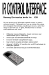
Imagine monitoring the entire 118 to 136 MHz Aircraft band with
no tuning! Then imagine being able to bring your receiver
onboard aircraft to hear what’s going on and not having to worry
about interference! This monitor give you access to air traffic
signals from aircraft and airports . . . just pop in the earbuds and
listen to what’s out there!
•
Monitors the entire aircraft band 118 to 136 MHz without tuning!
•
Passive design, can be used onboard aircraft, no local oscillator,
creates no interference.
•
Pick up local aircraft and tower communications
•
Volume and Squelch controls allow for discriminating listening
•
Fits in your pocket or clip to your belt
•
Patented circuit and design.
•
Runs on 9VDC and includes ear buds.
•
Great for air shows!
ABM1 • 1
PARTIAL LIST OF AVAILABLE KITS:
RAMSEY TRANSMITTER KITS
• FM10A, FM25B, FM30, FM Stereo Transmitters
• FM100B, FM35 Professional FM Stereo Transmitters
• AM1, AM25 AM Broadcast Band Transmitters
RAMSEY RECEIVER KITS
• FR1 FM Broadcast Receiver
• AR2 Digital Aircraft Band Receiver
• AR1 Aircraft Band Receiver
• SR2 Shortwave Receiver
• SC1 Shortwave Converter
RAMSEY HOBBY KITS
• LBC6K Laser Beam Communicator
• SG7 Personal Speed Radar
• SS70C Speech Scrambler/Descrambler
• DCI1 DTMF Controller
• LLS1 Laser Light Show
• MD3 Microwave Motion Detector
• LEDS1 LED Strobe Light
• BE66 Blinky Eyes Animated Display
• LTS1 Laser Trip Sensor
• ICI1C Infrared Switch Control Interface
RAMSEY AMATEUR RADIO KITS
• HR Series HF All Mode Receivers
• DDF1 Doppler Direction Finder Kit
• QRP Series HF CW Transmitters and QAMP Power Amplifiers
• CW7 CW Keyer
RAMSEY MINI-KITS
Many other kits are available for hobby, school, scouts and just plain FUN. New
kits are always under development. Write or call for our free Ramsey catalog.
Passive Air Band Monitor
Ramsey Electronics publication No. ABM1
December 2005
COPYRIGHT ©2005 by Ramsey Electronics, Inc. 590 Fishers Station Drive, Victor, New York
14564. All rights reserved. No portion of this publication may be copied or duplicated without the
written permission of Ramsey Electronics, Inc. Printed in the United States of America.
ABM1 • 2
Ramsey Publication No. ABM1
Manual Price Only $5.00
INSTRUCTION MANUAL FOR
PASSIVE AIR BAND
MONITOR
TABLE OF CONTENTS
Introduction .......................................... 4
Circuit Description................................ 4
What You Can Expect to Hear ............ 6
Parts List............................................ 10
Assembly Steps ................................. 12
Schematic .......................................... 14
ABM1 Alignment and Adjustment...... 20
Troubleshooting ................................. 21
Conclusion ......................................... 23
ABM1 Specifications.......................... 24
Parts Layout Diagram ........................ 25
Warranty ............................................ 27
RAMSEY ELECTRONICS, INC.
590 Fishers Station Drive
Victor, New York 14564
Phone (585) 924-4560
Fax (585) 924-4555
www.ramseykits.com
ABM1 • 3
INTRODUCTION
Everyone from aviation enthusiasts to armchair listeners to schoolchildren
can enjoy listening to aircraft and airport signals with the ABM1. It’s an Aircraft receiver that does not radiate RF signals so you can take it to the airport
and even onboard aircraft without worrying about causing interference. In order for the receiver to be non-interfering, no local oscillators or mixers are
used. The unit directly converts the entire Aircraft Band meaning that the
user can hear all local aircraft traffic at once. Stronger RF signals will produce a louder audio signal than weaker signals, making it easy for the user to
pick out a specific conversation to listen to. This also has the advantage of
allowing the user to hear both sides of a conversation without re-tuning the
receiver. In fact, you never tune the ABM1, making it perfect for beginners
and kids learning the fun of both electronics and aviation. We think you’re going to find the Airband Monitor kit a useful and educational receiver that you’ll
be enjoying for years to come.
CIRCUIT DESCRIPTION
We’ll take the circuit in bite size chunks and explore each section to see how
the kit works. Follow along on the schematic if you wish; we’ll work from input
to output.
Antenna Input/Audio Output
Jack J1 allows the connection of a standard 3.5mm headphone jack to the
ABM1. The headphones will provide two functions. Obviously they provide
the audio for the user to listen to the aircraft band. The headphone wires are
also used as an antenna for the ABM1. L2 is a high impedance to Radio
Frequencies (RF) keeping the RF from traveling back to the Audio Amplifier.
1st Band-pass Filter
C1 is a coupling capacitor that allows the RF signal picked up by the headphone wires to pass into the 1st Band-pass filter. This filter is made up of M1,
C2, L3, C3, M2, and C4. M1 and M2 are micro-strip inductors that are actually formed from traces on the circuit board. This filter is designed to pass
only frequencies between 118 MHz and 136 MHz, the aircraft band.
RF Amplifier
The purpose of this stage is to increase the signal strength of the previously
filtered signal. C5 is another coupling capacitor; it takes the 118 to 136 MHz
RF signal from the 1st Band-pass filter and allows it to move to the RF Amplifier while isolating DC. U1 is a Monolithic Amplifier that provides about 18 dB
of gain for our signal. Its frequency range is from DC to 1 GHz. Since component leads and foil runs can act as antennas at high frequencies C6 is
used to prevent high frequency signals from entering U1 directly from the air.
R1 sets the bias for the amplifier while C7 and C9 filter the power supply.
ABM1 • 4
2nd Band-pass Filter
The 2nd Band-pass filter is a copy of the first. Its job is to further filter the RF
signal. It consists of coupling capacitor C8, and filter components M3, C10,
L4, C11, C12, and M4.
AM Detector
The AM detector consists of C13; you guessed it, it’s another coupling capacitor that passes the signal to U2’s non-inverting input while isolating DC.
R6 provides the bias for the detector while C17 provides power supply filtering. C15 is used to prevent high frequency signals from entering U2 directly
from the air. R2 sets the input impedance of the stage to 51 ohms. This is
important for proper frequency response from the 2nd Band-pass filter, it
needs to see a 50 ohm load. C14 essentially places the inverting input at AC
ground. The Logarithmic Amplifier U2 provides a high amount of gain, detects or turns the RF signal in to audio, and provides a DC output voltage proportional to its input signal strength.
Squelch
The squelch circuit allows the user to set the RF signal level that the Audio
Amplifier will amplify and pass. C19 is a coupling capacitor that passes the
detected audio from U2 to the audio amplifier section while preventing U2’s
DC output from being affected by the setting of R11. R9 prevents the AC
output of U2 from being shorted to ground if the squelch is closed. R3, R4,
and R5 make up a voltage divider that allows the user to set the voltage
(squelch level) at U3 pin 3 through R7 (filtered by C16) between 0.1 VDC and
2.0 VDC. U3 is an operational amplifier being used as a comparator. This
circuit compares the voltage from the voltage divider and DC level from the
Detector’s output through R8 (filtered by C18). When the Detector’s DC
level, which is proportional to U2’s RF input, at U3 pin 2 falls below the level
set by the operator (U3 pin 3). U3’s output at pin 1 goes high (9 Volts) turning on Q1. Q1 is an N-channel Enhancement Mode Field Effect Transistor.
The positive voltage from the comparator U3, pin 1, is felt on the gate of Q1,
turning it on, which results in a very low Drain to Source resistance. This low
Drain to Source resistance shorts the audio signal coming through R9 to
ground. This prevents the audio from passing to the audio amplifier so nothing is heard in the headphones. When the input signal to U2 increases the
DC output voltage at U2 pin 4 will increase. When this voltage being felt on
U3 pin 2 increases above the voltage on U3 pin 3 (set by the user) U3 pin 1
will go low (0 Volts). With 0 Volts on the gate of Q1 it turns off which causes
the Drain to Source Resistance to become very high. With Q1’s Drain to
Source resistance high the detected audio from U2 is allowed to pass
through C19 and R9 into the Audio Amplifier. Now received audio is heard in
the headphones.
ABM1 • 5
Audio Amplifier
The Audio amplifier section consists of R11, the On/Off/Volume control. This
part turns the power on or off and adjusts the audio level sent to the headphones. C20 couples the audio signal to the Audio Amplifier, U4, while isolating DC. C21 keeps high frequencies out of the amplifier. C22 is a bypass capacitor. C23 sets the gain of the amplifier to approximately 200. C24 filters
the power supply. C25 is the output coupling cap. C26 and R12 are used to
prevent the amplifier from oscillating. L2 acts as a low impedance for audio
allowing it to pass to J1 and on to the headphones.
118-136 MHz, WHAT YOU CAN EXPECT TO HEAR
A basic fact about the VHF Aviation Band which even licensed pilots can overlook or forget is that communications are in the AM mode, not FM, as in the
case of the FM broadcast band immediately below it, and the VHF public service and Ham bands immediately above it.
No matter where you live you will be able to receive at least the airborne side
of many air traffic communications. You'll hear any aircraft you can see, PLUS
planes up to ten miles away and more, since VHF signals travel "line of sight."
An airliner at 35,000 feet altitude is still line of sight to your antenna. Similarly,
whatever ground stations you may hear are also determined by this "line of
sight" character of VHF communication. If there are no major obstacles between your antenna and an airport (tall buildings, hills, etc.), you'll be able to
hear both sides of many kinds of aviation communication. Be prepared for
them to be fast and to the point and for the same airplane to move to several
different frequencies in the span of a few minutes! Here's a brief listing of the
most common types of services in the NAS (National Airspace System) with
which pilots communicate:
Clearance Delivery
At most metropolitan airports, a pilot communicates with the FAA on a frequency called "Clearance Delivery" to obtain approval or clearance of the intended flight plan. This communication is done before contacting ground control for taxi instructions.
Ground Control
From the control tower, ground movements on ramps and taxiways are handled on the “Ground Control” frequency.
Control Tower
Runway and in-flight maneuvers near the airport usually within three miles
(takeoffs, local traffic patterns, final approaches and landings) are on the
“Control Tower” frequency.
ATIS – Automated Terminal Information System
ABM1 • 6
ATIS, is a repeated broadcast about basic weather information, runways in
use, and any special information such as closed taxiways or runways.
ASOS/AWOS – Automated Surface Observing System/Automated Weather
Observing System
This system is similar to ATIS but usually located at un-towered airports.
Approach Control & Departure Control
These air traffic radar controllers coordinate all flight operations in the vicinity
of busy metropolitan airport areas.
ARTCC – Air Route Traffic Control Center
When you hear a pilot talking with "Jacksonville Center" or "Indianapolis Center", you know the aircraft is really en route on a flight rather than just leaving
or just approaching a destination. A pilot will be in touch with several different
"Regional Centers" during a cross-country flight.
CTAF – Common Traffic Advisory Frequency
Airports without control towers are controlled by the pilots themselves and
they rely on the local CTAF frequency dedicated only to advisory communications between pilots and ground personnel such as fuel service operators. The
people on the ground can advise the pilot on the status of incoming or outgoing aircraft, but the pilot remains responsible for landing and takeoff decisions.
Typical CTAF frequencies are 122.7, 122.8 and 123.0 MHz. Unicom frequencies used at manned, towered airports for day to day business are 122.75,
122.85, and 122.95 MHz.
FSS - FAA Flight Service Stations
The FAA's network of Flight Service Stations keeps track of flight plans and
provides weather briefings and other services to pilots. Some advisory radio
communication takes place between pilots and a regional "FSS". If there is an
FSS in your local area but no airport control towers, the FSS radio frequency
will stay interesting. Typical frequencies are 122.1, 122.6, and 123.6 MHz.
Pilots always address the FSS by calling the FSS name followed by “Radio”.
ELT – Emergency Locator Transmitters
Emergency and guard channels are used by airplanes in flight operations during an emergency or talking on official business. This can be heard on
121.5MHz.
ACARS - Aircraft Communication Addressing and Reporting System
ACARS is a digital VHF radio data link which allows airline flight operations
departments to communicate with the various aircraft in their fleet. ACARS is
used by many civilian and business aircraft and is similar to “email for airplanes,". Each aircraft has its own unique address in the system. Traffic is
ABM1 • 7
routed via computers to the proper company, relieving some of the necessity
for routine voice communication. With ACARS, routine items such as departure reports, arrival reports, passenger loads, fuel data, engine performance
data and more can be retrieved from the aircraft at automatic intervals. This
transmission will sound like a short data burst to the ABM1 user.
THOSE FAST-TALKING PILOTS AND CONTROLLERS!
Aviation communication is brief but it is clear and full of meaning. Usually pilots repeat back exactly what they hear from a controller so that both know
that the message or instructions were correctly interpreted. If you are listening
in it’s hard to track everything said from a cockpit, particularly in big city areas.
Just to taxi, take off, and fly a few miles, a pilot may talk with 6 or 8 different
air traffic control operations, all on different frequencies, all within a few minutes! Here are the meanings of a few typical communications:
"Miami Center, Delta 545 Heavy out of three-zero for two-five."
Delta Flight 545 acknowledges Miami Center's clearance to descend from
30,000 feet to 25,000 feet altitude. The word "heavy" means that the plane is
a jumbo jet such as 747, DC-10, etc.
"Seneca 432 Lima cleared to outer marker. Contact Tower 118.7."
The local Approach Control is saying that the Piper Seneca with the N-number
(tail number) ending in "432L" is cleared to continue flying an instrument approach to the outer marker (a precision radio beacon located near the airport)
and should immediately call the airport radio control tower at 118.7 Mhz. This
message also implies that the approach controller does not expect to talk
again with that aircraft.
"Cessna 723, squawk 6750, climb and maintain five thousand."
A controller is telling the Cessna pilot to set the airplane's radar transponder to
code 6750, climb to and fly level at an altitude of 5000 feet.
"United 330, traffic at 9 o'clock, 4 miles, altitude unknown."
The controller alerts United Airlines flight #330 of radar contact with some
other aircraft off to the pilot's left at a 9 o'clock position. Since the unknown
plane's altitude is also unknown, both controller and pilot realize that it is a
smaller private plane not equipped with altitude-reporting equipment.
ELECTRONICS & FLYING: DOING IT "BY THE NUMBERS"
A peek at the sample FAA "instrument approach" chart for medium-large airports shows that pilots deal with many vitally important numbers and must do
so quickly. Among the numbers on that chart, can you find the air-ground
communications frequencies which can be heard on the ABM1 receiver? Can
you find frequencies for uses other than communications?
ABM1 • 8
ABM1 • 9
PARTS LIST
CAPACITORS
2 2.2pF ceramic disk capacitor [marked 2.2] (C3, C11)
2 5pF ceramic disk capacitor [marked 5] (C6, C15)
4 68pF ceramic disk capacitor [marked 62] (C2, C4, C10, C12)
8 1nF or 0.001uF ceramic disk capacitor [marked 102] (C1, C5, C8, C9,
C13, C14, C16, C21)
4 100nF or 0.1uF ceramic disk capacitor [marked 104] (C7, C17, C18,
C26)
2 1 uF electrolytic capacitor [cylindrical body with a stripe marked 1uF]
(C19, C20)
2 10 uF electrolytic capacitor [cylindrical body with a stripe marked 10uF]
(C22, C23)
2 100 uF electrolytic capacitor [cylindrical body with a stripe marked
100uF] (C24, C25)
RESISTORS
1 2 ohm resistor [red-black-gold] (R12)
1 51 ohm resistors [green-brown-black] (R2)
1 470 ohm resistor [yellow-violet-brown] (R1)
1 560 ohm resistor [green-blue-brown] (R6)
2 1k ohm resistors [brown-black-red] (R5, R7)
1 10k ohm resistors [brown-black-orange] (R9)
1 100k ohm resistors [brown-black-yellow] (R3)
1 330k ohm resistor [orange-orange-yellow] (R8)
1 1M ohm resistor [brown-black-green] (R10)
1 10k ohm thumbwheel linear potentiometer (R4)
1 10k ohm thumbwheel audio taper potentiometer w/switch (R11)
SEMICONDUCTORS
1 BS170 [marked BS170] (Q1)
1 MAR-1 [marked 01] (U1)
1 AD8307AR [marked AD8307AR] (U2)
1 LMC6482AIN [marked LMC6482AIN] (U3)
1 LM386 [marked LM386] (U4)
INDUCTORS
2 12uH inductor [looks like resistor but larger, brown-red-black-silver]
(L1, L2)
2 0.41uH 11t air core inductor [11 turns of wire] (L3, L4)
4 0.14uH inductor [part of circuit board, no actual parts] (M5, M6, ML7,
M8)
ABM1 • 10
MISCELLANEOUS COMPONENTS AND HARDWARE
1 3.5mm Stereo Jack NOSW [J1]
1 4 inches of 24 gauge Red/black twisted pair
1 Case Top
1 Case Bottom
1 Case Panel
4 Case screws
1 Belt Clip
1 Set of battery contacts
2 Thumbwheel for potentiometers
2 Thumbwheel screws
1 AR3 Rev 1.3 Circuit board
1 Ear Bud
REQUIRED, NOT SUPPLIED
1 9 Volt Battery
ABM1 • 11
ASSEMBLY STEPS
In ALL PC board assembly steps, our word "INSTALL" always means to do
this:
•
Insert the part, oriented or "pointed" correctly, into its holes in the PC
board.
•
If helpful, gently BEND the part's wire leads or tabs to hold it into place,
with the body of the part snugly against the top side ("component side") of
the circuit board.
•
Solder ALL wires or pins of the part.
•
Trim or "nip" all excess wire lengths extending beyond each solder
connection, taking care that wire trimmings do not become lodged in
solder connections.
One of the goals of the ABM1 design was to keep the receiver as small as
possible while trying to stay away from surface mount components. Staying
away from surface mount components makes the kit a lot easier to assemble.
You will notice that we had to use some SMT parts such as the MAR amplifier
and log amplifier IC that only come in a surface mount package. We have
preinstalled the log amplifier component to allow the assembler to keep their
sanity. You will also notice that inductors M1, M2, M3, and M4 are actually
made from foil runs on the circuit board. This means no actual physical parts
exist for these components.
Since part of our goal was to keep the kit small the components are spaced
very closely together. We highly recommend following the assembly
procedure to insure proper installation and identification of all parts and their
locations. Let’s get building and have some fun!
IC INSTALLATION
Find the circuit board. U2 (one of those pesky surface mount parts) has
been preinstalled for you. It has been mounted on the component side of
the board.
Find U1, the MAR-1 marked 01. This is the other surface mount part.
This component will be mounted and soldered on the same side of the
board as U2. Mount the MAR-1 so that its dot is on the same lead as the
dot on the circuit board or facing C5. All other components will be
mounted on this side of the board and soldered on the opposite side.
Install U3, the LMC6482AIN Operational Amplifier IC. It’s located near the
center of the PC board. You’ll see the PC board silkscreen shows a notch
ABM1 • 12
on one end of the part; this corresponds to the notch on the IC and shows
you which way to place the part. Line up the notches and make sure that
all pins are through the board. With no other parts installed (other than
surface mount) you can have the part sit flat on your bench and the board
will hold U3 in place. That way the part will sit flat on the board. That’s why
we’re putting the ICs in first! We typically solder the two corner pins, flip
the board over to check placement, then solder the rest. Be sure to solder
all 8 pins.
Install U4, the LM386 audio amplifier IC. It’s located next to U2. Again,
line up the notch on the part with the notch marked on the board, make
sure the part is seated flat, then solder all 8 pins.
ANTENNA INPUT/AUDIO OUTPUT CIRCUIT
Install J1, the 3.5mm phone jack. It is located on the narrow edge of the
board closest to U3. Make sure the part is flush to the board and square
to the edges. The part will tend to rotate counter-clockwise from square.
Solder all three pins.
Install L1, 12 uH inductor (brown-red-black-silver). L1 looks like a resistor
but is a bit larger. This part can be installed in either direction. It is
located next to J1. Make sure it does not cover any part of the mounting
hole.
Install L2, 12 uH inductor (brown-red-black-silver). Like L1 it can be
installed in either direction.
1ST BAND-PASS FILTER
Install C1, 1nF ceramic disk capacitor (marked 102). Disc capacitors have
no polarity so they can be installed in either direction.
M1 and M2 are inductors that are made with foil runs on the board. There
are no actual components to install.
Install C2, 68pF ceramic disk capacitor (marked 68).
Install L3, 0.41uH 11t air core inductor (11 turns of wire). Again, this part
can be installed in either direction. It will not sit flat on the board. Push it
down gently until the leads are snug (do not crush the coil). It should be
no higher than 1/8th of an inch.
Install C3, 2.2 pF ceramic disk capacitor (marked 2.2). It is very important
that this part is placed as close to the board as possible. You may need
to use pliers to pre-bend the leads.
ABM1 • 13
ABM1 • 14
ABM1 • 15
Install C4, 68pF ceramic disk capacitor (marked 68).
RF AMPLIFIER
Install C5, 1nF ceramic disk capacitor (marked 102).
Install C6, 5pF ceramic disk capacitor (marked 5 or 4.7). C6 is put in on a
45 degree angle. This is done to keep the foil run as short as possible as
part of good, standard RF (Radio Frequency) practice. Excess lead
length adds unwanted inductance in RF circuits.
U1 is already installed.
Install R1, 470 ohm resistor (yellow-violet-brown). This is another part put
in at a 45 degree angle for RF reasons. Resistors have no polarity and
can be installed in either direction. R1 is a one of three lay-down resistors
in the ABM1. It is important that the body rests flat on the circuit board.
Install C7, 100nF ceramic disk capacitor (marked 104).
Install C9, 1nF ceramic disk capacitor (marked 102).
2ND BAND-PASS FILTER
Install C8, 1nF ceramic disk capacitor (marked 102).
M3 and M4 are just like M1 and M2. They are made from foil runs on the
board. No actual components to install.
Install C10, 68pF ceramic disk capacitor (marked 68).
Install L4, 0.41uH 11t air core inductor (11 turns of wire).
Install C11, 2.2 pF ceramic disk capacitor (marked 2.2). It is very
important that this part is placed as close to the board as possible.
Install C12, 68pF ceramic disk capacitor (marked 68).
AM DETECTOR
Install C13, 1nF ceramic disk capacitor (marked 102).
Install R2, 51 ohm resistor (green-brown-black). This is the second laydown resistor. Install it just like R1.
Install C14, 1nF ceramic disk capacitor (marked 102).
Install C15, 5pF ceramic disk capacitor (marked 5 or 4.7).
ABM1 • 16
U2 is already installed.
Install C17, 100nF ceramic disk capacitor (marked 104).
Install R6, 560 ohm resistor (green-blue-brown). This is our 3rd and last
lay-down resistor.
SQUELCH CIRCUIT
Install C19, 1uF electrolytic capacitor. Electrolytic caps have a polarity
and must be installed correctly in order to work . . . and in some cases in
order not to blow up when power is applied! You’ll note that the legs of the
part are different lengths and there is a stripe or band down one side of
the capacitor that corresponds to the shorter of the two leads. This is the
negative side of the cap. The silkscreen and Parts Layout Diagram will
show where the positive lead is to be placed by a “+” sign on the board.
Orient the part with the longer lead in the “+” hole and solder the part in.
The legs of this part may need to be straightened so that the bottom of the
capacitor body will sit flat on the PCB. If this part doesn’t sit flat on the
PCB the case will not fit together properly.
Install R9, 10k ohm resistor (brown-black-orange). R9 and all the rest of
the resistors are stand-up resistors. A stand-up resistor has one end of
the resistor body resting on the circuit board with its lead through the pad.
It is important that this end of the resistor actually rests on the board. The
other end is up in the air with the lead bent over going though the other
pad. It is important to make this bent lead as short as possible. Refer to
the Parts Layout Diagram; it has a circle on the pad the resistor body is to
rest on. Proper orientation of stand-up resistors may be important for RF
or for physical spacing reasons.
Install R8, 330k ohm resistor (orange-orange-yellow).
U3 is already installed
Install C18, 100nF ceramic disk capacitor (marked 104).
Install C16, 1nF ceramic disk capacitor (marked 102).
Install R10, 1M ohm resistor (brown-black-green).
Install Q1, a BS170 (marked BS170) FET in a TO-92 package. The part
has a flat side with the number on it and you’ll see the outline showing
where to place this flat side on the PC board silkscreen. Bend the center
lead out to fit in the holes and push the part down close to the circuit
board without forcing. Solder the transistor.
Install R7, 1k ohm resistor (brown-black-red).
ABM1 • 17
Install R3, 100k ohm resistor (brown-black-yellow). This part is located at
the notched end of U4.
Install R5, 1k ohm resistor (brown -black-red). This part is located in the
corner of the board that does not have anything mounted yet.
Install R4, 10k ohm potentiometer (marked B10K). The three
potentiometer contact leads (middle leads) may need to be bent slightly to
fit in the holes. This was done intentionally to keep the part in the board
while soldering. Ensure all five leads are sitting squarely on their
shoulders before soldering.
AUDIO AMPLIFIER
Install R11, 10k ohm potentiometer with switch (marked A10K). Install this
part exactly like R4. Ensure all five leads are sitting squarely on their
shoulders before soldering.
Install C20, 1uF electrolytic capacitor. Be careful to check the polarity;
refer to step X to refresh your memory if necessary.
Install C21, 1nF ceramic disk capacitor (marked 102).
U4 is already installed.
Install C24, 100uF electrolytic capacitor. Verify the polarity using the
Parts Layout Diagram.
Install C22, 10uF electrolytic capacitor. Watch polarity!
Install C25, 100uF electrolytic capacitor. Verify the polarity using the
Parts Layout Diagram.
Install C23, 10uF electrolytic capacitor. Yes, check polarity before
installing.
Install C26, 100nF ceramic disk capacitor (marked 104).
Install R12, 2 ohm resistor (red-black-gold).
BATTERY WIRING
Find the 4 inch Red and Black twisted pair (wire). Strip back the insulation
on both ends of each wire 3/16 of an inch from the ends. Tin the four
ends of the wire. Be careful not to use too much solder; use just enough
to hold the strands of wire together. Insert one end of the Red wire into
the BAT1 (+ ) pad and one end of the Black wire into the BAT1(-) pad.
You will find these pads on each side of C21.
ABM1 • 18
Find the two battery clips. Look carefully at the two clips; the one with the
narrower contact is the (+) clip and to be attached to the Red wire. The
wider contact is the (-) clip and is to be attached to the Black wire. Feed
the Red wire though the appropriate clip from the battery contact side (not
the side that clips into the case). Solder the Red wire into place. Repeat
the process for the black wire and appropriate clip.
CIRCUIT BOARD AND FRONT PANEL ASSEMBLY
Remove the Battery door from the case bottom (the bottom contains the
battery box and belt clip).
Adjust the case bottom so that the battery box is facing you with the
battery door opening down.
Place the circuit board in the case bottom so that J1 comes out the open
end (away from you).
Lift the end of the circuit board that contains J1 and place the front panel
over J1. Line up the edge of the front panel to fit in the groove of the case
bottom. Drop the circuit board and front panel into place.
Bring the battery wires down toward the battery box alongside R11.
Below R11, bring the wires down the left side of the case and R9 toward
the battery box.
Place the battery clips through the battery cavity.
Bring one of the battery clips up through the clip slot on the left side of the
battery box with the wire side of the clip up. The clip should snap into
place.
Repeat previous step for the other battery clip.
THUMBWHEEL ASSEMBLY
Line up the notch on a thumbwheel with the post on R11. Install the
screw to hold the thumbwheel in place.
Repeat for second thumbwheel and R4.
ABM1 • 19
ABM1 ALIGNMENT AND ADJUSTMENT
TUNING THE ABM1
The ABM1 does not require any frequency tuning. It will receive the entire
Aircraft Band at one time with the audio volume level being greatest for the
strongest signals. The ABM1 is a total band monitor so you will hear any
signal generated in that band. Since this is a total band receiver the bandpass filters have been specially designed to be wideband. The aircraft band is
located between the FM broadcast band and one of the Pager bands. At
times and in certain locations low level signals from these bands may be
detected and heard in the ABM1. To reduce this align the band-pass filters.
Weaker signals may also be eliminated by adjusting the squelch control.
BAND-PASS FILTER ALIGNMENT
Your unit will probably work great without any alignment. Some users may
find that the FM Broadcast band is easily picked up by the ABM1. To reduce
FM band reception the band-pass filters can be tuned. Alignment of the
ABM1 band-pass filters consists of stretching or compressing coils L3 and L4.
Start off with the coils as they were when received (fully compressed). Start
spreading the coils apart simultaneously a little at a time keeping both coils
about the same. If you start to hear paging signals (152 to 159 MHz) then you
have spread the coils too far. In a heavy RF environment you may have to
balance the coils between a little FM and a little paging.
SQUELCH ADJUSTMENTS
The ABM1 uses your headphones as an antenna. Since each brand and
model of headphones is different the reception for each will be different.
Some headphones will provide better reception than others. Different areas of
the country have different RF environments. Some areas will have more RF
or higher noise than others. The squelch circuit will react a bit differently
depending on the antenna and RF noise in the area of use. Building the kit
with the parts supplied, it should work well for all different conditions, however,
the user may want to optimize their squelch circuit for the area they are in and
the headphones they wish to use. To get the squelch to open closer to the
low end of the potentiometer’s (R4) range decrease R5. To get the squelch to
close nearer to the upper end of the potentiometer’s (R4) range decrease R3.
ABM1 • 20
ABM1 TROUBLESHOOTING
While we had hoped that it wouldn’t come to this, if you are having trouble with
your receiver, here are a few suggestions.
By far the most common sources of problems are misplaced parts or poor
solder connections. It’s always best to take a break before searching for bad
connections. A good way of checking component placement is to double
check the assembly steps going backwards from the last steps to the first.
Bright lighting and a magnifying aid can be helpful in identifying soldering
problems.
Use a methodical, logical troubleshooting technique. Most problems can be
solved using common sense. A volt-ohm meter and a clear head are usually
all that are needed to correct any problem.
No sound from ABM1.
Check these items in the following order:
Verify the Squelch control is fully counter-clockwise.
Check that the Battery Clip is soldered in with the correct polarity (+)
connected to the red wire and (-) connected to the black wire.
Check that the Battery polarity is correct. The battery’s (+) terminal
connects to the smaller tab.
Is your Battery Good? New does not necessarily mean good. Check for
9 Volts without the battery connected to the ABM1. If possible place a
1k ohm resistor across the battery contacts during the test. This places
a load on the battery which gives a better indication of the battery’s
condition than open load testing:
Connect battery to the ABM1 and switch on the unit, verify the
battery still has an output of approximately 9 Volts.
If not, turn off the unit and look for solder bridges and
components improperly installed. Verify the polarity and
orientation of all IC chips, transistors, and electrolytic capacitors.
If it has 9 volts, check the AM Detector, Audio Amp, and Squelch
circuits carefully for solder bridges, and proper component
placement.
Verify pin 1 of U2 is less than 0.2 Volts DC, if not see: “Squelch Circuit
Not Functioning”.
ABM1 • 21
No Signals can be heard
Check MAR-1SM (U1):
Check the input pin for 2.5 Volts DC +/- 10 %. This is the pin with
the dot.
Check the output pin for 4.7 Volts DC +/- 10 %. This is the pin
across from the dot.
Check the 1st Band-pass Filter, 2nd Band-pass Filter and the AM
Detector circuits for solder bridges, misplaced components,
polarity of components, and orientation of components.
Check U2’s supply Voltage at U1 pin 6 or 7; it should be 4.3 Volts DC +/20 %
Erratic Operation:
Check all solder connections for a complete, shiny solder joint.
Squelch Circuit Not Functioning.
Check U3 for the following Voltages (all voltages +/- 10 %):
Pin 2, varies between 0.2 Volts and 2 Volts DC with input signal
strength.
Pin 3, voltage should be 0.08 VDC with R7 fully counterclockwise, 1.0 VDC with R7 fully clockwise.
Pin 8, equals the Battery Voltage (approximately 9 Volts).
Pin 4, 0 Volts DC
Pin 1, 0 Volts DC with R7 fully counter-clockwise, 9 Volts with R7
fully clockwise.
If all else fails, check the inside back cover of this manual for instructions on
how to send the kit in for repair. Hopefully you’ll never get to that point but it’s
nice to know that there’s someone out there to help you if you do.
ABM1 • 22
CONCLUSION
If you enjoyed this Ramsey product, there are plenty more to choose from in
our catalog - write or call today!
We sincerely hope that you will enjoy the use of this Ramsey product. As always, we have tried to compose our manual in the easiest, most “user
friendly” format possible. As our customers, we value your opinions, comments, and additions that you would like to see in future publications. Please
submit comments or ideas to:
Ramsey Electronics Inc.
Attn. Hobby Kit Department
590 Fishers Station Drive
Victor, NY 14564
or email us at: [email protected]
And once again, thanks from the folks at Ramsey!
ABM1 • 23
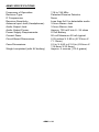
ABM1 SPECIFICATIONS
Frequency of Operation:
Receiver Type:
IF Frequencies:
Receiver Sensitivity:
Antenna Input Jack (Headphones):
Audio Output Jack:
Audio Output Power:
Power Supply Requirements:
Current Draw:
Circuit Board Dimensions:
Case Dimensions:
Weight completed (with 9V battery)
118 to 136 MHz
Patented Passive Detector
None
Less than 2uV for detectable audio
3.5mm Stereo Jack
3.5mm Stereo Jack
Approx. 700 mW into 8 - 24 ohms
9 Volt Battery
50 mA Maximum 20 mA typical
2.25 inches X 2.80 in (57.23mm X
71.13mm)
2.5 in X 4.60 in X 0.9 in (63.5mm X
116.8mm X 22.9mm)
Approx. 4 ounces (113.4 grams)
ABM1 • 24
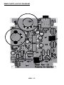
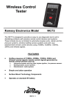
ABM1 PARTS LAYOUT DIAGRAM
ABM1 • 25
This page intentionally left blank.
ABM1 • 26
The Ramsey Kit Warranty
Please read carefully BEFORE calling or writing in about your kit. Most
problems can be solved without contacting the factory.
Notice that this is not a "fine print" warranty. We want you to understand your rights and ours too! All
Ramsey kits will work if assembled properly. The very fact that your kit includes this new manual is your
assurance that a team of knowledgeable people have field-tested several "copies" of this kit straight
from the Ramsey Inventory. If you need help, please read through your manual carefully, all information
required to properly build and test your kit is contained within the pages! However, customer
satisfaction is our goal, so in the event that you do have a problem, take note of the following.
1. DEFECTIVE PARTS: It's always easy to blame a part for a problem in your kit, Before you conclude
that a part may be bad, thoroughly check your work. Today's semiconductors and passive components
have reached incredibly high reliability levels, and its sad to say that our human construction skills have
not! But on rare occasions a sour component can slip through. All our kit parts carry the Ramsey
Electronics Warranty that they are free from defects for a full ninety (90) days from the date of
purchase. Defective parts will be replaced promptly at our expense. If you suspect any part to be
defective, please mail it to our factory for testing and replacement. Please send only the defective part
(s), not the entire kit. The part(s) MUST be returned to us in suitable condition for testing. Please be
aware that testing can usually determine if the part was truly defective or damaged by assembly or
usage. Don't be afraid of telling us that you 'blew-it', we're all human and in most cases, replacement
parts are very reasonably priced.
2. MISSING PARTS: Before assuming a part value is incorrect, check the parts listing carefully to see if
it is a critical value such as a specific coil or IC, or whether a RANGE of values is suitable (such as
"100 to 500 uF"). Often times, common sense will solve a mysterious missing part problem. If you're
missing five 10K ohm resistors and received five extra 1K resistors, you can pretty much be assured
that the '1K ohm' resistors are actually the 'missing' 10 K parts ("Hum-m-m, I guess the 'red' band really
does look orange!") Ramsey Electronics project kits are packed with pride in the USA. If you believe
we packed an incorrect part or omitted a part clearly indicated in your assembly manual as supplied
with the basic kit by Ramsey, please write or call us with information on the part you need and proof of
kit purchase.
3. FACTORY REPAIR OF ASSEMBLED KITS:
To qualify for Ramsey Electronics factory repair, kits MUST:
1. NOT be assembled with acid core solder or flux.
2. NOT be modified in any manner.
3. BE returned in fully-assembled form, not partially assembled.
4. BE accompanied by the proper repair fee. No repair will be undertaken until we have received the
MINIMUM repair fee (1/2 hour labor) of $25.00, or authorization to charge it to your credit card account.
5. INCLUDE a description of the problem and legible return address. DO NOT send a separate letter;
include all correspondence with the unit. Please do not include your own hardware such as
nonRamsey cabinets, knobs, cables, external battery packs and the like. Ramsey Electronics, Inc.,
reserves the right to refuse repair on ANY item in which we find excessive problems or damage due to
construction methods. To assist customers in such situations, Ramsey Electronics, Inc., reserves the
right to solve their needs on a case-by-case basis.
The repair is $50.00 per hour, regardless of the cost of the kit. Please understand that our technicians
are not volunteers and that set-up, testing, diagnosis, repair and repacking and paperwork can take
nearly an hour of paid employee time on even a simple kit. Of course, if we find that a part was
defective in manufacture, there will be no charge to repair your kit (But please realize that our
technicians know the difference between a defective part and parts burned out or damaged through
improper use or assembly).
4. REFUNDS: You are given ten (10) days to examine our products. If you are not satisfied, you may
return your unassembled kit with all the parts and instructions and proof of purchase to the factory for a
full refund. The return package should be packed securely. Insurance is recommended. Please do not
cause needless delays, read all information carefully.
ABM1 • 27
TABLE OF CONTENTS
Introduction ..........................................4
Circuit Description ................................4
Parts List ........................................... 10
Assembly Steps ................................ 12
Schematic ......................................... 14
ABM1 Specifications ......................... 24
Parts Layout Diagram ....................... 25
Warranty............................................ 27
RAMSEY ELECTRONICS, INC.
590 Fishers Station Drive
Victor, New York 14564
Phone
(585) 924-4560
Fax
(585) 924-4555
www.ramseykits.com
Manual Price Only: $5.00
Ramsey Publication No. ABM1
Assembly and Instruction manual for:
RAMSEY MODEL NO. ABM1
ABM1 • 28