1
Ramsey Electronics Model No.
ICI1
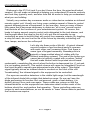
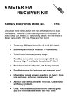
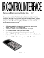
Do you have a ton of old remote controls around, or even a
universal remote? Put those to real use by training this unique
kit to recognize the remotes, and allow you to turn a set of four
relays on and off! Turn on lights, TVs that have no remote,
small appliances and more!
•
IR Receiver module with sensitive element can receive your
remote control up to 11 meters away.
•
•
•
•
Control up to four devices independently via relays.
•
Convenient LED indicator lets you know Infra Red status.
E-Z screw terminals hookup for each output.
Easy to train to recognize almost any remote control!
Universal 7-15V AC or DC operation. Use our AC-1 wall adapter for
battery free operation.
ICI1 Page 1
RAMSEY TRANSMITTER KITS
• FM10A, FM25B FM Stereo Transmitters
• FM100B Professional FM Stereo Transmitter
• TXE433 or 916 Transmitter & Encoder Module
• RXD433 or 916 Data Receiver& Decoder
• RR1 Wired remote repeater
• RRW1 Wireless remote repeater
RAMSEY RECEIVER KITS
• FR1 FM Broadcast Receiver
• AR1 Aircraft Band Receiver
• SR1 Short-wave Receiver
RAMSEY HOBBY KITS
• WEB1 Walking Electronic Bug
• LEDS1 LED Strobe
• BE66 Blinky Eyes
• EDF1 Electronic Dripping Faucet
• TFM3 Tri-Field Meter
• LC1 Inductance-Capacitance Meter
RAMSEY AMATEUR RADIO KITS
• HR Series HF All Mode Receivers
• QRP Series HF CW Transmitters
• CW7 CW Keyer
• DDF1 Doppler Direction Finder
• QRP Power Amplifiers
RAMSEY MINI-KITS
Many other kits are available for hobby, school, Scouts and just plain FUN. New
kits are always under development. Write or call for our free Ramsey catalog.
ICI1 REMOTE INTERFACE KIT MANUAL
Ramsey Electronics publication No. MICI1 Revision 1.4
First printing: July 2002 JJH
COPYRIGHT 2002 by Ramsey Electronics, Inc. 590 Fishers Station Drive, Victor, New York
14564. All rights reserved. No portion of this publication may be copied or duplicated without the
written permission of Ramsey Electronics, Inc. Printed in the United States of America.
ICI1 Page 2
Ramsey Publication No. MICI1
Price $5.00
KIT ASSEMBLY
AND INSTRUCTION MANUAL FOR
ICI1 IR CONTROL
INTERFACE KIT
TABLE OF CONTENTS
Introduction ...........................................4
Theory of Operation ..............................5
Learn As You Build ...............................7
Parts List ...............................................9
Schematic Diagram .............................10
Parts Placement Diagram ...................11
Assembly Steps...................................12
Testing.................................................17
Programming.......................................18
Wiring and Custom Application ...........21
Troubleshooting ..................................22
Specifications ......................................25
Warranty..............................................27
RAMSEY ELECTRONICS, INC.
590 Fishers Station Drive
Victor, New York 14564
Phone (585) 924-4560
Fax (585) 924-4555
www.ramseykits.com
ICI1 Page 3
ICI1 INTRODUCTION
Welcome to the ICI1 kit (and if you don’t have the time, the wired and tested
version). We will make an attempt at helping you understand IR remote controls
and how they typically work, and also how this kit works to help you understand
what you are building.
Virtually any modern day consumer audio or video device contains an infrared
remote control unit. Usually our living room contains several of these to control
several different pieces of equipment. In fact we often have so many of these
little gems that it becomes necessary to obtain an “all in one” remote control
that controls all the functions of your entertainment system. Of course, this
leads to having several remote control units delegated to the junk drawer, and
that brought about the idea for this kit. Let’s put the old remotes to use
controlling an easy to build kit that will control four separate outputs. By toggling
a relay for each, we can live the life of the future by remotely controlling our
fans, lamps, and even the coffee pot!
Let’s dig into these units a little bit. A typical infrared
remote contains a few functional parts in common
with each other; we’ll examine them. First there is
some type of keypad assembly. Nowadays this is
typically a large molded sheet of rubber with the
buttons protruding outward. The end of the button you
cannot see is typically coated with a carbon “button”
that will make contact with the printed circuit board
underneath, completing the circuit when the button is depressed (no, it’ not sad,
it is just making contact!). This switch closure will cause an Integrated Circuit on
the circuit board to repeat a pre-determined code at the output. This digital
signal typically drives an infrared diode to conduct on the front of the unit
“broadcasting” the infrared signal to the equipment to be controlled.
Our eyes are sensitive detectors in the visible light range, but the wavelength
of the infrared diode falls outside that detection range. So we can’t see the
diode performing its function. But rest assured, given a fresh battery, it is
dutifully doing it over and over again. These codes are unique so that the
infrared detector on the equipment can determine what function each of the
buttons should be, and perform that operation. These controlling codes are
unique to each manufacturer, so our kit needs to “learn” these codes to perform
the functions we require.
ICI1 Page 4
ICI1 THEORY OF OPERATION
At first look the ICI1 may seem quite simple, but there is actually quite a bit
to it on the “inside” of the components. Many items are inside the IR receiver
part (U4) and if built up with discrete components it would never fit in this little
kit case. Inside this part there’s an IR detector diode, amplifier, AGC circuit,
band pass filter, a peak-hold circuit, an integrator, comparators, and an output
amp. Heck, the part is a kit in itself! Just be glad it is in one nice module all
ready to go. The pre-programmed microcontroller houses several thousand
transistors, memory locations, and an oscillator circuit. As a matter of fact,
building this kit 20 years ago would have been next to impossible with the
complexity of the circuit(s) to accomplish the tasks at hand.
SAMPLE
START
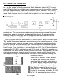
Your IR remote controls send data on a 38kHz carrier, much like radio does.
The digital information is actually modulated onto the carrier frequency. A few
of the reasons for this is to increase range, and decrease interference from
other IR sources such as ambient light. Remember that infrared can also be
thought of as “heat”; it is one of the components of energy that comes from a
heat source. The modulation is transmitted in an OOK (on off keying) fashion,
meaning the IR LED is switched on and off at a rate of 38kHz for a certain duration for a one, and another certain duration for a zero, with pauses of no carrier in-between each one and zero. A common remote control format does
some special things to differentiate a one from a zero for digital sending and
receiving of data.
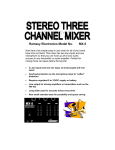
0 Bit
When the IR detector “sees” a 38kHz
IR signal, the output of the detector
goes low (it is inverted), when there is
no 38kHz signal, the output idles high.
On the output of the IR detector you
won’t see the 38kHz, just the data that
the 38kHz represents from your IR remote control. This allows the remote
control to save power since the IR LED
is “on” for a minimal amount of time.
1 Bit
ICI1 Page 5
Typically a remote control will send data in a format consisting of time slices.
To send a zero, the IR LED will be off for one time slice, and then toggled at a
rate of 38kHz for the second time slice. To send a one, the IR remote will use
three time slices. Off for two time slices, and on for one. This makes things
easy on the receiver side, because we just have to look from the edge of the
first on-to-off transition to the middle of the second time slice (1 1/2 time slices
from the start) to determine the bit that was sent.
It’s important to note, however is that most remote controls send a unique
first code that can be identified for each and every button, as well as each and
every remote control. Some remotes will send a full data stream over and over
as long as you hold the button down, up to 48 bits per data stream. Other remotes will only send this full data stream once for the first depression, and
then a very short repeat code usually of only one bit, to save on batteries.
The ICI1 recognizes the full codes, and discards the short repeat codes
unless you are holding a relay in position. If we didn’t do this, we couldn’t tell
one button from another! You will find that with some remotes, you need to
press the button twice to train the ICI1 to remember a certain button. This
means the remote you are using is using repeat codes. Other remotes just
require you to press and hold the button, so these are the ones that send the
same code over and over.
One other variance is the data rate from the remote. Generally most remotes
send at a rate of 2400 Hz time slices, but others send at only 1200 Hz time
slices. This presents a problem on slower remotes since the sample period
will always lie in a high or low portion of the subsequent data, meaning we will
receive nothing but ones or zeros. There is a speed jumper you can install to
allow the ICI1 to work with these remotes. If an incorrect speed remote control
is detected, the micro controller emits a special beep to let you know the format is wrong. Then you can switch the jumper over to the other speed and try
again, then you will get either a recognized beep if you have trained the button, or an unrecognized beep if you have not.
When you train the ICI1, the micro controller looks at the IR data stream and
rejects those codes it sees as useless or unverified. The ICI1 looks at the data
from the remote sensor, makes sure it is not a repeat code, checks that it is
not the wrong speed, and then compares it to a previous send before saving
the new value in the Flash memory of the controller. That is why you have to
press the button twice on some remotes; so you can get the same code for
verification before saving.
When the ICI1 is normally receiving, it looks at the data stream, and compares it to what was saved. If there is a match, the corresponding relay is set
or cleared depending on the mode. If there are repeat codes within the allotted
time, the state of the relay is held until there are no more signals seen for that
time.
ICI1 Page 6
There are two option switches OP1, and OP2 which allow you to switch the
modes of Relay 1&2 with OP1, and Relay 3&4 with OP2. If the option jumper
is in, then the corresponding relays are in “auto-toggle” mode. It means that as
long as the remote button is pressed, the relay will remain energized. Let go of
the button, and it de-energizes the coil. The typical action of the relay is in toggle mode. Press the remote button, and the relay changes state. If the initial
state was off, it turns on, if it was on, it then shuts off. This is useful for switching external circuits on and off without having to hold down the button.
RAMSEY “LEARN-AS-YOU-BUILD” ASSEMBLY STRATEGY
Be sure to read through all of the steps, and check the boxes as you go to be
sure you didn't miss any important steps. Although you may be in a hurry to see
results, before you switch on the power check all wiring and capacitors for
proper orientation. Also check the board for any possible solder shorts, and/or
cold solder joints. All of these mistakes could have detrimental effects on your
kit - not to mention your ego!
Kit building tips:
Use a good soldering technique - let your soldering iron tip gently heat the
traces to which you are soldering, heating both wires and pads simultaneously.
Apply the solder on the iron and the pad when the pad is hot enough to melt the
solder. The finished joint should look like a drop of water on paper, somewhat
soaked in.
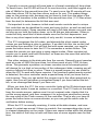
Mount all electrical parts on the top side of the board provided. To install
parts, the component should be placed flat to the board, and the leads are bent
on the backside of the board to prevent the part from falling out before
soldering (1). The part is then soldered securely to the board (2-4), and the
remaining lead length is then clipped off (5). Notice how the solder joint looks
on close up, clean and smooth with no holes or sharp points (6).
ICI1 Page 7
Although we know that you are anxious to complete the assembly of your
infrared controller kit it is best to follow the step-by-step instructions in this
manual. Try to avoid the urge to jump ahead installing components.
Since you may appreciate some warm-up soldering practice as well as a
chance to put some landmarks on the PC board, we’ll first install some of the
larger components. This will also help us to get acquainted with the up-down,
left-right orientation of the circuit board. Remember that all of the components
will be mounted on the component side of the circuit board and soldered on the
solder side of the circuit board (the side that contains the printed circuit traces).
Have a look at the parts layout diagram to help with your assembly.
Use the boxes to check off your progress.
Check all received parts against the parts list. The parts list describes the
various markings that may be found on the kit parts. Carefully sort the parts into
small piles to aid in finding the correct part at the required time.
We will begin by installing the input and output connectors on the rear side of
the circuit board. These will act as our landmark components and make the
orientation of the rest of the parts a bit easier.
Proper Component Installation:
NOTE TO NEWCOMERS: If you are a first time kit builder we hope you find
this manual easier to understand than you may have expected. Each part in the
kit is checked off as you go, while a detailed description of each part is given. If
you follow each step in the manual in order, and practice good soldering and kit
building skills, the kit is next to fail-safe. If a problem does occur, the manual
will lead you through step by step in the troubleshooting guide until you find the
problem and are able to correct it.
ICI1 Page 8
PARTS SUPPLIED WITH YOUR ICI1 KIT
Capacitors
2 10 pF ceramic capacitors (Marked 10 or 10K) (C1,8)
4 0.1 µF ceramic capacitors (Marked 104) (C2,3,6,7)
1 10 µF electrolytic capacitor (C5)
1 1000 µF electrolytic capacitor (C4)
Resistors
1 10 ohm resistor (brown-black-black) (R13)
4 100 ohm (brown-black-brown) (R14,15,16,17)
1 220 ohm resistor (red-red-brown) (R5)
5 1K ohm resistors (brown-black-red) (R1,2,3,4,20)
6 10K ohms (brown-black-orange) (R7,8,9,10,11,12)
1 1M ohm resistor (brown-black-green) (R18)
Semiconductors and Integrated Circuits
5
5
1
1
1
1
1N4002 Rectifier Diode (Black body with white stripe marked 4002)
(D1,2,3,4,6)
2N3904 NPN transistor (Marked 2N3904) (Q1,2,3,4,5)
78L05 5V Voltage Regulator (Marked 78L05 in transistor-like
package) (VR1)
68HC908JK1 Pre-programmed microcontroller (U1)
IR Sensor Module (U2 or U3, see instructions)
Large Green LED (D5)
Miscellaneous Components
1 20 pin IC socket for microcontroller U1
4 2 screw terminal jack (J1,2,3,4)
1 2.1 mm DC power jack (J7)
5 2-pin headers (J9,10,11,12,13)
5 Jumper Blocks
1 DPDT PC mount pushbutton switch (S1)
1 Mini toggle pushbutton switch (S2)
4 9 Volt Relay (K1,2,3,4)
1 9.8304 MHz crystal (Marked 9.8304) (X1)
1 Mini-speaker (SP1)
ICI1 Page 9
ICI1 SCHEMATIC DIAGRAM
ICI1 Page 10
ICI1 PARTS PLACEMENT DIAGRAM
ICI1 Page 11
ICI1 REMOTE CONTROLLER INTERFACE ASSEMBLY
Assembly of the ICI1 is fairly easy, as we use all through hole components,
but it requires some time and some patience. We will start with the side that
has the power jack, and we will move from there using the power jack as a
reference.
1. Identify and install power connector J7 toward the rear of the printed
circuit board. Gently slide the leads through the circuit board until the
connector is flush to the board with the connection hole facing towards the
outside of the kit and solder all three connections. Use enough heat to
flow the ground connection completely; this may take a little while
depending on the wattage of your soldering pencil. Use caution when
soldering the other two leads so that too much time or heat is not applied;
it may cause the printed circuit trace to lift away from the circuit board
2. Install J4, the 2-screw terminal connector. Make sure and mount it so
that the receiving holes are facing the outside edge of the board. This is
where you will be mounting the interface wires when you are finished, so
make sure that the openings face outward. The screw terminal makes it
easy to work with, and you can change the wires without a soldering iron.
Again, these jacks will deal with the strain of interconnection to “the
outside world”, so use enough solder for a robust solder joint.
3. In the same manner, install J1, J2 and J3, also two screw terminal
connectors.
4. Moving to the other end of the circuit board, install pushbutton switch
S1 by inserting all six leads through the circuit board. The switch should fit
flat to the circuit board before soldering.
Great job up until now! Take a moment to check your previous solder joints for
“opens” where the solder did not completely flow around the connection or
solder bridges between closely spaced pads. It seems the best time to identify
these types of problems is now when you’re focused on this section of the
board, saving you time trying to retrace your steps later.
Now we will build the power supply portion of the circuit. We use a 78L05
voltage regulation circuit to provide for a clean trouble free voltage source for
the infrared interface. It is critical that the power source be free of noise and
any hum for proper operation of the kit. The 78xx series of voltage regulators
is extensively used in many of today's modern electronic appliances to
perform this task.
5. Identify D6, the 1N4002 diode (black epoxy case with a polarity “band”
denoting the cathode (negative) side of the diode). Install as shown in the
parts placement diagram, noting the proper orientation of the polarity
band. Since a diode only will conduct when it is forward biased, this diode
acts as a “reverse voltage” protection circuit. Diodes are often used as
ICI1 Page 12
“one-way switches” in this manner to protect internal circuitry. In our case
we use the diode “double duty”, because if you use an AC wall adapter this
diode will act as a half wave rectifier to provide a DC voltage to the input of
the voltage regulator IC.
6. Identify C4, the 1000 uF electrolytic capacitor (cylindrical component and
marked 1000 uF). Electrolytic capacitors are polarized with a (+) and (-)
lead and must be installed in the correct orientation. Ordinarily only the
negative side is marked on the capacitor body with a dark band and the (-)
sign clearly shown, while the PC boards will usually show the (+) hole
location. Normally the part also has one lead that is shorter than the other
and this also corresponds to the negative lead. Use care to ensure proper
polarity. See the parts diagram for proper placement. The capacitor should
fit snugly down to the PC board. Save those long leads that you trim off to
fashion jumper connections later in the assembly.
7. Identify VR1, the 78L05 voltage regulator IC (the three leaded
component labeled 78L05). This component is in a TO-92 package, and
again proper orientation is required for correct operation. The component
should be mounted so that the “flat” side of the part mounts facing the
previously installed capacitor. Use caution not to stress the leads when
inserting or soldering. Use the parts layout diagram as a guide for proper
orientation. This part works by “smoothing” out any junk that may reside on
the non-regulated side of the part. It also allows you to run this kit from a
wide range of supply voltages on the input, while it keeps the output to 5V.
8. Install C5, the 10 uF electrolytic capacitor (marked 10 uF). Remember to
observe polarity with those electrolytic capacitors! Check the parts
placement diagram for correct orientation.
Recheck your work up until now, trimming those component leads as you go.
Next we will work on the “feedback” portion of the circuit that lets us know we
are receiving and executing commands from the remote control unit, both using
an audible beep and light emitting diode.
A
9. Install D2 on the other side of
the board (the Green LED). This
K
LED will blink when the IR
detector sees data to let you know that an IR signal has been seen. D2 only
works in one direction. After all it is a diode, so have a look at the diagram.
The long lead indicates the Anode, the shorter is the Cathode, as well as
the larger fat base that you may see inside of the LED case. This Cathode
is also indicated by the flat side of the LED if you look at it end-on; you
really can’t miss on this one. If you look at the board we have a flat side
indicated on the silk screen. Orient the LED so it’s flat side is the same. Do
NOT mount the LED flush to the board, but mount it as high as possible, or
about 1 1/4” off of the board. The LED will eventually be bent over to peek
out of the front of a case.
ICI1 Page 13
9. Install C7, a 0.1uF ceramic capacitor (marked 104). Disc capacitors are
not polarized, so either direction is alright.
10. Install R13, 10 ohm resistor (brown-black-black). Resistors are not
polarized; they may mount in either direction.
11. Identify and install the mini speaker. SP1 (small round object with two
leads protruding). You may notice a “+” sign adjacent to where the leads
attach, but for our application polarity is not a concern. Mount it adjacent
to R13, as shown in the parts placement diagram.
12. Identify the small signal transistor Q5 (three leads marked 3904).
Notice that there is a “flat” side of the component. Install transistor Q5,
being sure to mount the flat side as shown in the parts diagram. This
transistor is the driver for the mini speaker and it provides enough current
to make the speaker “beep”.
13. Install R5, a 220 ohm resistor (red-red-brown).
14. Install R20, 1K ohm resistor (brown-black-red).
15. Install R12, 10K ohm resistor (brown-black-orange).
That’s getting the hang of it! Believe it or not you’re already about halfway
through the assembly of your kit. Recheck your solder connections and touch
up any less than perfect ones. Watch out for any solder bridges on the solder
connections.
Lets get to work on that microcontroller. We will start with the connections that
“talk” to the IC and work our way over to the chip.
16. Identify the jumper block headers (or strip of headers) included with
your kit. If not already done, snap the pins off in pairs so that you have five
sets of two pins. These will install on the circuit board with the longer ends
facing upward to provide connection points to configure the microcontroller IC. Use caution soldering these as the heat from the tip of your
iron will quickly travel down the metal post, and can give you a nasty burn
if your are holding it in place with an extra finger. Install headers in the
J13, J12, J11, J10 and J9 position.
17. Install resistors R7, R8, R9, R10, and R11, all 10K ohm (brown blackorange) into their respective positions. These resistors are referred to as
“pull ups”, as they set the voltage at the associated pins of the
microcontroller to +5 volts, whereas if the previously installed header is
shorted, the DC value on the pin becomes a low, or logic zero. They “pull”
the electric potential on the pins “up” to the +5 volt level; that’s where the
name comes from.
18. Install the socket for U1, the Motorola 68HRC908 20 pin micro
controller IC. It doesn’t matter which way you install the socket but it
definitely matters which way you place the IC in the socket. Don’t be afraid
ICI1 Page 14
to use enough solder and heat for a good solder connection, and be extra
careful not to “bridge” any solder connections together. It usually works
best to solder the two “corner” pads first to hold the IC in place, and then
work through the remaining 18 connections. Once the socket is soldered,
insert the microcontroller IC into it. Pay particular attention to the
orientation of this device. Make sure to align the notch or dot associated
with pin one with the notch shown in the parts layout diagram. It may be
helpful to gently “rock” the IC on its side on a hard flat surface before
installing to align the rows of pins so that they slide in easily.
19. Using a scrap component lead, form a jumper wire and install in the
JMP1 holes. Jumpers act like electronic “bridges” that carry power or
signals over active traces on the circuit trace side of the board. Solder
both connections on the bottom side of the circuit board.
20. In the same manner, form and install jumper wire JMP2.
21. Install C3, 0.1uF ceramic capacitor (Marked 104).
22. Install X1, the quartz crystal in the silver can labeled 9.M8304. This
piece of quartz actually vibrates at a specified frequency when a voltage is
applied to it. This sets up a reference clock for the microcontroller so it can
execute the pre-programmed code routine contained within it. Install the
crystal in the X1 position in either direction, making sure to solder both
leads.
23. Install C8, 10 pf ceramic disc capacitor (marked 10).
24. Install R18, 1 Megohm resistor (brown-black-green). Notice that this
component is mounted “standing up” in place. Consult the parts
placement diagram for the correct position.
25. Install C2, a 0.1uF ceramic capacitor (Marked 104).
26. Install C6, another 0.1uF ceramic capacitor (Marked 104).
Notice at this point there is a position for R6; this is not installed and was
meant as a place holder for future use.
27. Install C1, the remaining 10 pF disc (marked 10).
28. Install S2, the PC mount pushbutton switch. We will use this when
programming our completed kit.
Whew! That was some work. But we are almost done! It’s a good time now to
recheck all your work up to this point. Carefully inspect the circuit board for
stray leads or open solder connections, trim and touch up any that need work.
Next we will install the output relays that control the external devices. Notice
how symmetrical the outputs appear; each is exactly the same as the one next
to it. To take advantage of this, we will use common components and place
them in all four output stages at once, this will save a lot of back and forth with
ICI1 Page 15
different components.
29. Install “lay-down” 1K ohm resistors R2, R1, R3, and R4 (brown-blackred) .
30. Install “stand-up” resistors R14, R15, R16, R17, all 100 ohm (brownblack-brown).
31. Identify the remaining small signal transistors Q1, Q2, Q3, Q4 (three
leads marked 3904). Notice that there is a “flat” side of the component.
Install these transistors, being sure to mount the flat side as shown in the
parts diagram. These transistor are the drivers for the relays, they
provides enough current to energized the relay coil.
32. Install the remaining 1N4002 diodes in the D1, D2, D3, and D4
positions. Yep, you remembered, those diodes are polarized so that the
banded end must face in the direction shown in the parts diagram.
But wait, the relays run on an applied DC voltage, and the diodes are not used
“in series” like we did before (on step 5) . . . what is their purpose? Well, a
relay employs a large coil of wire to generate its magnetic field, so the energy
is stored in the field. When the relay is abruptly shut off, the field collapses
and a counter EMF is produced causing an inductive voltage spike. The diode
limits this to a small voltage, protecting the relay coil and any component
“upstream” of it. Its is always a good design practice to include it, and you will
almost always see one across the coil of a DC relay.
33. Carefully position and install relays K1, K2, K3, and K4. Note that the
pins are offset such that the component will only fit one way. Use care to
ensure that all four leads protrude through the circuit board before
soldering.
34. On to the last component the infrared detector. Depending on the
vendor for this component, you may have received one that contains three
mounting pins “in line” or one with offset pins Either will work, and they
perform exactly the same, it is just a question of which was “in stock” at
the time we placed our order. In either case, the detector is positioned
such that the “bump” on the package is facing out, and the part should
NOT be placed flat on the board. The component should actually be
positioned about 3/4” (~20 mm) above the board so that it “looks” through
the opening in the pre punched panel.
CONGRATULATIONS !
Your Remote Control Interface kit is now complete! Have a final look over
your work, paying particular attention to the orientation of diodes, capacitors,
and IC’s. Remember that any problems you find now can save time and effort
after the unit has been cased up and final assembled.
ICI1 Page 16
TESTING AND PROGRAMMING YOUR ICI1
To begin testing the ICI1 we will need the following items:
AC Power supply between 9 and 15VAC or..
DC power supply between 9 and 15VDC.
A remote control
Its finally time to apply power to your kit. Please be sure before you do that
you clear the bench of any scrap component leads and have one final look at
your solder connections before you proceed. Again, time spent here can
prevent problems encountered during testing and can avoid damaging any of
the components.
Recalling that the relays may be set for either momentary or toggle (on-off)
operation, it’s time to decide how you want to configure the outputs. If you
desire momentary operation, install a jumper strap in the respective OP1&2 or
OP 3&4 position.
Configure the jumper strap in the OP 1&2 position.
Configure the jumper strap in the OP 3&4 position.
Remember that these can be easily changed at a later time, so we
recommend that for initial test you omit these jumpers so that it is easier to
verify the operation of each individual relay.
Place a two pin header shorting connector in the SEL0 and SEL1 position.
This selects the 0,0 configuration for the first button. We pull down the two
pins of the microcontroller thru a 10 K ohm resistor to set the voltages at zero,
designating a digital “0” state for programming. When we continue the
programming, we will use these jumpers to count up in binary for all four
states.
Configure the jumper strap in the O SEL position.
Configure the jumper strap in the 1 SEL position.
Please note that when using these “shorting jumpers” it is common practice to
position them on only one pin, offset such that they do not make contact with
the other pin in order to set the associated jumper with the logic “1”, or 5 VDC
state. In this configuration the 10 K ohm resistor will pull the associated pin
high. This also helps to keep you from misplacing the jumpers and will keep
them handy for future programming. By setting the jumpers on these pins
you’re getting ready to program the 0,0 position on the ICI1.
ICI1 Page 17
Set the power switch to the “off” position, and plug in a suitable power source
to the power input connector. The correct range of values for supply voltage
is 9 - 15 VAC or VDC, and the current capacity is between 200 - 250 mA. Our
AC125 transformer is the recommended source for this kit, but any wall wart
will do.
Upon energizing the switch, a short chirp will be heard from the speaker and
the LED should illuminate. The LED should be lit, initially; this will change after
we program the microcontroller IC.
PROGRAMMING YOUR ICI1
Now that we have made it through the initial “turn on” steps it is time to
program the microcontroller for your individual codes. Remember to install
some fresh batteries in your remote control, and aim the infrared LED towards
the photo sensor. Depress one of the buttons that you intend to use for
operation (I.e. button #1 for the first relay). The LED should begin to blink as
the unit receives the infrared code from the transmitter. This testing verifies
the operation of the detector and associated circuitry. It will also provide some
clues to the operation of the remote control unit (remember we talked about
this in the theory of operation) as you may see a long “burst” of code,
followed by successive shorter pulse trains, or you may see the pulse train
being repeated over and over. If you have access to an oscilloscope you can
even observe this pulse train on the detector “output “pin, which is tied to pins
1 and 19 of the microcontroller.
Now we will set our controller to the “learn” mode to memorize the pulse trains
from our remote, and configure the jumpers to learn four codes as we move
along.
Press and hold the “learn” button.
Now the unit is waiting to memorize the code for your remote. Depress the
button on your remote control unit and the LED on the front panel will blink.
The speaker will chirp when the code is learned. Just to be safe, push the
button on your remote control unit twice to ensure that the micro has
memorized your remote controls pulse train.
Uh-oh… a raspberry!
If upon initial programming your speaker emits a two tone “raspberry”, don’t
fret! This simply means that your remote control is transmitting data at a
slower rate than expected by the current jumper settings. If this is the case,
install the jumper across the “speed” terminals on the circuit board. This will
allow the unit to work at the slower pulse train rate just as effectively as the
faster rate.
If necessary, install the jumper across the “speed” header.
ICI1 Page 18
Back to programming. Now that the first, or digital 0,0, location has been
programmed it is time to advance to the next three states. We will need to
count in binary, or base two. There is no such thing as a number two in binary,
only ones and zero’s (making it the choice of electronic circuits). The following
chart will describe the header jumper sequence for the binary count, and we
have left some room to jot down the function key you are using on your
remote. Be careful when programming to use the SEL 0 and SEL 1 jumpers
in the correct order, as the order of 1’s and 0’s are important when identifying
the buttons.
Jumper Settings
SEL 1
SEL 0
0
0
0
1
1
0
1
1
Remote
Button
Binary Num Decimal Num
00
0
01
1
10
2
11
3
You have already programmed the 0,0 state; let’s get to work on the
remaining three states.
ICI1 Page 19
Move the jumper in the SEL 0 connection so that it is only connected to
one pin, offset such that it will not make contact with the other pin in order
to set the associated jumper with the logic “1”, or 5 VDC state. This sets
the IC to learn in the 0, 1 state (or decimal state 1).
Depress the learn button and memorize the second code.
In the same manner, program the remaining two codes, incrementing the
jumpers as you move along.
For the #3 relay (decimal number 2 and binary 10) you’ll put the jumper
header back on the SEL0 pins and take it off the SEL1 pins so that it only
contacts one pin. For the last setting, relay #4, (decimal number 3 and binary
II) you’ll remove the jumpers so that neither of them is across either the SEL0
or SEL1 pins. Well, that’s it for programming! Now we are ready to put the
unit to the test and listen to those relays click!
With all the states programmed, depress the first programmed button on
your remote. The relay in the K1 position should toggle. Depress the
remote button again, and the relay will toggle to the other state.
If you wish the relay to remain on only momentarily (while the button is
depressed) install either the OP1,2 and/or the OP3,4 jumpers. By installing
these, the processor knows that you would like to control two (or all four)
outputs in a momentary fashion.
USING THE ICI1
Well, there really isn’t much of a secret to using the ICI1, but we thought
some wiring ideas would help. Primarily you will want to wire to the ICI1’s four
outputs to control some separate functions. The relay contacts effectively
isolate the ICI1 from the circuit or appliance you wish to control, so that both
AC and DC appliances may be controlled. Have a look at the following
diagrams for help in configuring your remote decoder.
ICI1 Page 20
WIRING AND CUSTOM APPLICATION SUGGESTIONS
Using your DCI1 for a variety of applications is very simple. You just need to
keep in mind the ratings for the relay contacts listed on the specification page
to avoid any problems and use a common sense approach for personal
safety. If you need to operate a simple low voltage DC circuit or switch on and
off a low wattage 120 VAC lighting application, interface your wiring directly to
the J1 through J4 screw terminals and you’re off to the races! For heavily inductive loads such as a large motor or applications that exceed the power ratings of the relays, the following diagrams will help you get started wiring the
DCI1 as a trigger source for a larger relay or similar device.
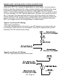
Typical Low Power DC Wiring:
-LED switch application
- Note that this application will work for any DC appliance (as long as the current ratings of the relay are not exceeded). Use care in applying the correct
polarity to the DC device when wiring.
Typical Low Power AC Wiring:
-120 VAC light being switched on Hot side.
(Black-Hot)
(White-Neutral)
ICI1 Page 21
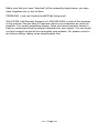
Typical High Power Relay:
-DCI1 used to trigger another Higher Power relay.
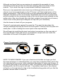
A few other important notes:
It is recommended that all external connections be fused for safety, especially
if you are connecting to 120VAC line voltage. Please choose the correct fuse
size for your individual application. Proper fusing is critical to the safe operation of your kit, please take the time to properly insulate any high voltage or
current contacts made externally to your unit.
TROUBLESHOOTING GUIDE
If your ICI does not work at all, recheck the following:
•
correct orientation of VR1 and U1 (see PC board layout diagram).
•
You should be able to measure the voltage on the input and output terminals of voltage regulator VR1. The input should be whatever the supply
voltage is specified at, while the output should be 5 VDC +/- 5%.
•
correct polarity of all electrolytic capacitors.
•
correct orientation of diodes D1 – D6
•
all solder connections
ICI1 Page 22
PROBLEM: The green LED doesn’t light up when I aim my remote at it.
SOLUTION: There are a few things that can go wrong here, so we will go from
the most likely to the least.
1
You forgot to turn on the power, or your DC adapter isn’t compatible (the
polarity is reversed).
2
You installed the green LED in backwards. Please check the orientation.
3
Your remote control’s battery is shot. Replace the battery.
4
Junior poured a coke and some ice cream into it. Take it apart and clean it
with warm water and a touch of dish detergent.
5
It is an ancient remote that has a hammer and chimes inside. Those just
won’t work, this is for IR remotes only.
6
You are trying to relay an IR remote that is modulated at some other frequency than 38kHz. There are some other ranges available but 38kHz is
by far the most common. Most consumer components operate at 38kHz.
This product ONLY works at 38kHz.
PROBLEM: The LED stays constantly lit.
SOLUTION: The detector is too near the IR LED/ or a noise source is saturating it. The IR detector can become saturated and remain on, jamming the
unit. Reposition the IR LED to aim away from the detector or even use some
creative “shielding” tape to shield the input to the detector.
STILL HAVING TROUBLE?
While we had hoped that it wouldn’t come to this, if you are still having trouble
with your IR controller, here are a few additional suggestions.
Use a methodical, logical troubleshooting technique. Most problems can be
solved using common sense. A volt-ohm meter and a clear head are usually
all that are needed to correct any problem. Most problems are due to
misplaced parts and/or bad solder connections. Working backwards through
the assembly steps will often lead you to the problem. Revisit the extensive
theory of operation included in this manual and try to apply it to your specific
problem.
Have another set of eyes look at your work. Here at the shop we have often
run into a “stone wall” of a problem only to have a fellow technician see our
obvious error. It is sometimes very difficult to see your own mistake; taking a
break can often solve this common problem.
ICI1 Page 23
Make sure that you have “checked” all the assembly steps boxes; you may
have forgotten one or two of them.
PROBLEM: I just can’t make the &#^$^@! thing work!
SOLUTION: Call Ramsey Support at 1-585-924-4560 or look at the warranty
in this manual. We are here to help and reduce your frustration as much as
possible. It is usually something simple. Have your board revision handy to
help our technicians find the proper schematic for your needs. You can email
our tech support as well at the ramseykits.com website. Oh, please count to
ten before calling, taking some deep breaths first...
ICI1 Page 24
ICI1 INFRARED CONTROLLER INTERFACE SPECIFICATIONS
Here are few of the commonly requested specifications for the ICI1:
J1, 2, 3, and 4 Relay Outputs
- Contact Rating: 5 A, 120 VAC / 28 VDC (Resistive)
- Rated Contact Current: 5 A
- Max. Contact Capacity: 1250VA AC, 150W DC
- Contact Arrangement: SPST-NO
- Contact Material: AG Alloy
- Note: Not intended for heavily inductive loads such as large motors.
J5 Power Input
- Input working voltage range: 9 - 15 VAC or VDC
- Max ICI1 current draw is between 200 - 250 mA.
Miscellaneous Information
- PCB Dimensions: 4.7” L x 4” W (max component height: 0.9”)
CONCLUSION
We sincerely hope that you enjoy the use of this Ramsey product. As always,
we have tried to compose our manual in the easiest, most user-friendly format
that is possible. As our customers, we value your opinions, comments, and
additions that you would like to see in future publications. Please submit
comments or ideas to:
Ramsey Electronics Inc.
Attn. Hobby Kit Department
590 Fishers Station Drive
Victor, NY 14564
Please also feel free to visit our Website at www.ramseykits.com and offer
your observations to other kit enthusiasts as well.
And once again, thanks from the folks here at Ramsey!
ICI1 Page 25
ICI1 Page 26
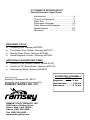
The Ramsey Kit Warranty
Please read carefully BEFORE calling or writing in about your kit. Most problems
can be solved without contacting the factory.
Notice that this is not a "fine print" warranty. We want you to understand your rights and ours too! All
Ramsey kits will work if assembled properly. The very fact that your kit includes this new manual is your
assurance that a team of knowledgeable people have field-tested several "copies" of this kit straight from
the Ramsey Inventory. If you need help, please read through your manual carefully. All information
required to properly build and test your kit is contained within the pages!
1. DEFECTIVE PARTS: It's always easy to blame a part for a problem in your kit, Before you conclude
that a part may be bad, thoroughly check your work. Today's semiconductors and passive components
have reached incredibly high reliability levels, and it’s sad to say that our human construction skills have
not! But on rare occasions a sour component can slip through. All our kit parts carry the Ramsey
Electronics Warranty that they are free from defects for a full ninety (90) days from the date of purchase.
Defective parts will be replaced promptly at our expense. If you suspect any part to be defective, please
mail it to our factory for testing and replacement. Please send only the defective part(s), not the entire kit.
The part(s) MUST be returned to us in suitable condition for testing. Please be aware that testing can
usually determine if the part was truly defective or damaged by assembly or usage. Don't be afraid of
telling us that you 'blew-it', we're all human and in most cases, replacement parts are very reasonably
priced.
2. MISSING PARTS: Before assuming a part value is incorrect, check the parts listing carefully to see if it
is a critical value such as a specific coil or IC, or whether a RANGE of values is suitable (such as "100 to
500 uF"). Often times, common sense will solve a mysterious missing part problem. If you're missing five
10K ohm resistors and received five extra 1K resistors, you can pretty much be assured that the '1K ohm'
resistors are actually the 'missing' 10 K parts ("Hum-m-m, I guess the 'red' band really does look orange!")
Ramsey Electronics project kits are packed with pride in the USA. If you believe we packed an incorrect
part or omitted a part clearly indicated in your assembly manual as supplied with the basic kit by Ramsey,
please write or call us with information on the part you need and proof of kit purchase.
3. FACTORY REPAIR OF ASSEMBLED KITS:
To qualify for Ramsey Electronics factory repair, kits MUST:
1. NOT be assembled with acid core solder or flux.
2. NOT be modified in any manner.
3. BE returned in fully-assembled form, not partially assembled.
4. BE accompanied by the proper repair fee. No repair will be undertaken until we have received the
MINIMUM repair fee (1 hour labor) of $49.00, or authorization to charge it to your credit card account.
5. INCLUDE a description of the problem and legible return address. DO NOT send a separate letter;
include all correspondence with the unit. Please do not include your own hardware such as non-Ramsey
cabinets, knobs, cables, external battery packs and the like. Ramsey Electronics, Inc., reserves the right
to refuse repair on ANY item in which we find excessive problems or damage due to construction
methods. To assist customers in such situations, Ramsey Electronics, Inc., reserves the right to solve their
needs on a case-by-case basis.
The repair is $49.00 per hour, regardless of the cost of the kit. Please understand that our technicians are
not volunteers and that set-up, testing, diagnosis, repair and repacking and paperwork can take nearly an
hour of paid employee time on even a simple kit. Of course, if we find that a part was defective in
manufacture, there will be no charge to repair your kit (But please realize that our technicians know the
difference between a defective part and parts burned out or damaged through improper use or assembly).
4. REFUNDS: You are given ten (10) days to examine our products. If you are not satisfied, you may
return your unassembled kit with all the parts and instructions and proof of purchase to the factory for a full
refund. The return package should be packed securely. Insurance is recommended. Please do not cause
needless delays, read all information carefully.
ICI1 Page 27
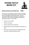
ICI1 REMOTE INTERFACE KIT
Quick Reference Page Guide
Introduction .......................................... 4
Theory of Operation .............................. 5
Parts List ............................................... 9
Schematic Diagram............................. 10
Parts Placement Diagram ................... 11
Specifications...................................... 26
Warranty ............................................. 27
REQUIRED TOOLS
• Soldering Iron Ramsey #RTS06
• Thin Rosin Core Solder Ramsey #RTS12
• Needle Nose Pliers Ramsey #RTS05
• Small Diagonal Cutters Ramsey #RTS04
ADDITIONAL SUGGESTED ITEMS
• Soldering Iron Holder/Cleaner (RS64-2078)
• Holder for PC Board/Parts Ramsey #RTS13,
• Desoldering Braid Ramsey #RTS08
Price: $5.00
Ramsey Publication No. MICI1
Assembly and Instruction manual for:
RAMSEY MODEL NO. ICI1
RAMSEY ELECTRONICS, INC.
590 Fishers Station Drive
Victor, New York 14564
ICI1 Page 28
Phone (585) 924-4560
Fax (585) 924-4555
www.ramseykits.com
ESTIMATED ASSEMBLY
TIME
Beginner ...............2 hrs
Intermediate .........1.25 hrs
Advanced .............0.75 hrs