1
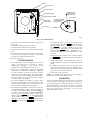
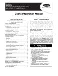
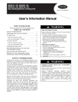
CRSTATUS003B00
48/50PD05---06, 48/50HG014---028, 48/50PG03---28
SINGLE ---PACKAGE ROOFTOP
WITH COMFORTLINKt CONTROLS
FAN STATUS SWITCH ACCESSORY
Installation Instructions
IMPORTANT: There are two different design revision
48/50HG units currently being produced. Because of these
differences, there are two different versions of this accessory. This
accessory literature covers accessories manufactured for units with
design revision 1. Design revision 0 units are not covered in this
accessory book.To determine the design revision, refer to the full
unit model number. See Fig. 1 for an example of an HG model
number. The design revision number in the model number
nomenclature is located in position 13.
Understand the signal words DANGER, WARNING, and
CAUTION. These words are used with the safety--alert symbol.
DANGER identifies the most serious hazards which will result in
severe personal injury or death. WARNING signifies a hazard
which could result in personal injury or death. CAUTION is used
to identify unsafe practices which may result in minor personal
injury or product and property damage. NOTE is used to highlight
suggestions which will result in enhanced installation, reliability, or
operation.
DESIGN REVISION NUMBER
NOTE: The fan status switch can be installed to monitor indoor
fan status (ON/OFF). Follow the procedures below and perform
the steps necessary to install the fan status switch.
Position No.
Example:
9
10
11
12
13
14
15
16
4 8 H G D 0 1 6 A
1
2
3
4
5
6
7
8
A
C
6
1
1
A
A
INSTALLATION
!
C07172
Fig. 1 -- Model Number Chart
QTY
1
2
1
2
PART NUMBER
HK06WC028
AL56AU166
50TG503595
AL56AU126
SAFETY CONSIDERATIONS
Installation and servicing of air--conditioning equipment can be
hazardous due to system pressure and electrical components. Only
trained and qualified service personnel should install, repair, or
service air--conditioning equipment.
Untrained personnel can perform the basic maintenance functions
of replacing filters. All other operations should be performed by
trained service personnel. When working on air--conditioning
equipment, observe precautions in the literature, tags and labels
attached to the unit, and other safety precautions that may apply.
Follow all safety codes. Wear safety glasses and work gloves. Use
quenching cloth for unbrazing operations. Have fire extinguishers
available for all brazing operations.
.
Recognize safety information. This is the safety--alert symbol
When you see this symbol on the unit and in instructions or
manuals, be alert to the potential for personal injury.
Copyright 2010 CAC / BDP D 7310 W. Morris St. D Indianapolis, IN 46231
ELECTRICAL OPERATION HAZARD
Failure to follow this warning could result in personal injury
and/or death.
PACKAGE CONTENTS
DESCRIPTION
Switch
Screw — 8-18 x 1/2 in.
Long Control Tube
Screw — 6-20 x 1/2 in.
WARNING
Printed in U.S.A.
Prior to installation of this accessory, make sure all power is
disconnected to the unit and locked out.
!
CAUTION
EQUIPMENT DAMAGE HAZARD
Failure to follow this caution may result in damage to
equipment.
When removing panels from the unit, be careful not to damage
the roof or other surfaces with the panels.
1. Turn off power to the unit.
2. Open the blower access door on the unit.
3. Mount the switch on the fan housing in the Fan Section as
shown in Fig. 2, using the screws provided.
NOTE: To ensure proper operation of the switch, the switch must
be installed vertically with the pneumatic ports pointed down.
4. Mount the pick--up tube to the fan housing using the
6--20 screws provided.
NOTE: The arrow of the pick--up tube should point down as
shown in Fig. 2.
Edition Date: 1/10
Manufacturer reserves the right to change, at any time, specifications and designs without notice and without obligations.
Catalog No:IIK---CRSTAT03---01
Replaces: 48/50H,P--- 6SI
WIRE TRAY
WIRE ROUTING
FAN STATUS SWITCH
REMOVE FOIL TAPE
FROM SENSOR HOLE
BEFORE INSTALLING
ADJUSTMENT SCREW
CONTROL TUBE (SMALL DIAMETER)
PICK-UP TUBE
COUPLING
CONTROL TUBE
(LARGE DIAMETER)
TUBE MUST BE MOUNTED
WITH ARROW POINTING
DOWN AS SHOWN
PICK UP TUBE
C08455
Fig. 2 -- Fan Switch Location
5. Connect the long control tube to the higher—pressure port
marked “H”.
6. Connect the coupling to the long control tube.
7. Connect the short control tube to the coupling.
8. Connect the short control tube to pick--up tube installed in
Step 4.
9. The wires for switch are located near the fan status switch.
Connect the gray wire (FS--1) to Terminal 1 and the black
wire (FS--3) to Terminal 3 (normally open).
10. Restore power to unit.
CONFIGURATION
1. The control system must be configured to use the fan
switch. A password may be required to edit the
configurations, depending on the previous settings
configured in the unit. Default password is ”1111”.
2. There are two configurations to control the Fan Status
feature. The first configuration is Shut Down on IDF Failure. This determines if the unit will shut down upon
activation of the fan failure switch. The default value is
“YES”, indicating that the unit WILL shut down should the
fan switch activate. To de--activate this feature, configure
the unit to “NO” (see steps below).
3. The second configuration is required to select the switch
type, either normally open (1) or normally closed (2). The
default setting for “FN.SW” is (0), or no switch. For use of
this accessory, the setting should be changed to “1”.
4. To configure the ComfortLink™ control, use the arrow keys
on the Scrolling Marquee display to scroll the red LED on
the display to the “UNIT” position and press ENTER . If it
is desired to change the setting of “IDF.F” (Fatal IDF), use
the arrow keys to scroll down until the display shows
“IDF.F”, and press ENTER key. At the Fatal IDF (IDF.F)
setting (default is YES), press ENTER (YES should be
flashing). Use the arrow keys to change the setting and press
ENTER again. Now press ESCAPE to save the setting.
5. To configure the switch type, use the arrow keys to scroll
down to “FN.SW”, and press ENTER . At the Fan Switch
(FN.SW) setting (default is “0” which means no switch),
press ENTER (“0” should be flashing). Use the arrow
keys to change the configuration to “1” for a normally open
switch, and press ENTER . Using a configuration of “2”
(normally closed switch) is not recommended for this
application.
6. Configuration of the fan switch is now complete. Pressing
the ESCAPE key several times will return the display to
the auto scroll setting.
7. Consult the Controls and Troubleshooting Guide for
complete instructions on using the ComfortLinkt control
system.
8. To configure switch, place the unit in Fan Only mode.
Using a flat head screwdriver, rotate the adjustment screw
until the pressure switch closes. Rotate the adjustment screw
in the same direction another 2 full turns.
9. Close and secure all access doors.
NOTE: For 48/50PD units, make sure the fan is running at
minimum fan speed when performing the above.
OPERATION
If there is a digital indicator light on the thermostat, it will be lit
when the indoor fan is operating. If the indoor fan is being told to
operate by the thermostat, and the indicator light is not lit, service
the unit immediately. If a space temperature probe or a thermostat
without an indicator light is being used, the indoor fan operation
status can be observed at the unit display, or over the Carrier
Comfort Network (if installed).
2