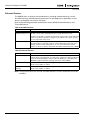
1
Intelligent Technologies
QCPort Starter Network Adapter Product
(QSNAP)
Installation and User Manual
Publication No. MN05001001E
February 2002
New
Intelligent Technologies (IT.) QSNAP
February 2002
Important Notice – Please Read
The product discussed in this literature is subject to terms and conditions outlined in
appropriate Eaton’s Cutler-Hammer selling policies. The sole source governing the
rights and remedies of any purchaser of this equipment is the relevant Eaton’s
Cutler-Hammer selling policy.
NO WARRANTIES, EXPRESS OR IMPLIED, INCLUDING WARRANTIES OF FITNESS
FOR A PARTICULAR PURPOSE OR MERCHANTABILITY, OR WARRANTIES ARISING
FROM COURSE OF DEALING OR USAGE OF TRADE, ARE MADE REGARDING THE
INFORMATION, RECOMMENDATIONS AND DESCRIPTIONS CONTAINED HEREIN. In
no event will Eaton’s Cutler-Hammer be responsible to the purchaser or user in
contract, in tort (including negligence), strict liability or otherwise for any special,
indirect, incidental or consequential damage or loss whatsoever, including but not
limited to damage or loss of use of equipment, plant or power system, cost of
capital, loss of power, additional expenses in the use of existing power facilities, or
claims against the purchaser or user by its customers resulting from the use of the
information, recommendations and descriptions contained herein.
Cover Photo: QSNAP on IT. E101 Starter
Pub. No. MN05001001E
Intelligent Technologies (IT.) QSNAP
February 2002
Table of Contents
PRODUCT OVERVIEW
Description . . . . . . . . . . . . . . . . . . . . . . . . . . . . . . . . . . . . . . . . . . . . . . . . . . . . . . . . .
Features and Benefits . . . . . . . . . . . . . . . . . . . . . . . . . . . . . . . . . . . . . . . . . . . . . . . .
Safety . . . . . . . . . . . . . . . . . . . . . . . . . . . . . . . . . . . . . . . . . . . . . . . . . . . . . . . . . . . . .
Environmental Ratings . . . . . . . . . . . . . . . . . . . . . . . . . . . . . . . . . . . . . . . . . . . . . . .
Approvals/Certifications . . . . . . . . . . . . . . . . . . . . . . . . . . . . . . . . . . . . . . . . . . . . . .
Catalog Numbering System . . . . . . . . . . . . . . . . . . . . . . . . . . . . . . . . . . . . . . . . . . .
PHYSICAL FEATURES
Physical Description . . . . . . . . . . . . . . . . . . . . . . . . . . . . . . . . . . . . . . . . . . . . . . . . .
Dimensions . . . . . . . . . . . . . . . . . . . . . . . . . . . . . . . . . . . . . . . . . . . . . . . . . . . . . . . .
Power Source. . . . . . . . . . . . . . . . . . . . . . . . . . . . . . . . . . . . . . . . . . . . . . . . . . . . . . .
OPERATION
“Out of Box” Operation . . . . . . . . . . . . . . . . . . . . . . . . . . . . . . . . . . . . . . . . . . . . . .
Typical Application . . . . . . . . . . . . . . . . . . . . . . . . . . . . . . . . . . . . . . . . . . . . . . . . . .
Enhanced Features . . . . . . . . . . . . . . . . . . . . . . . . . . . . . . . . . . . . . . . . . . . . . . . . . .
Input/Output Data . . . . . . . . . . . . . . . . . . . . . . . . . . . . . . . . . . . . . . . . . . . . . . . . . . .
Input Data . . . . . . . . . . . . . . . . . . . . . . . . . . . . . . . . . . . . . . . . . . . . . . . . . . . . .
Output Data . . . . . . . . . . . . . . . . . . . . . . . . . . . . . . . . . . . . . . . . . . . . . . . . . . . .
Status LED . . . . . . . . . . . . . . . . . . . . . . . . . . . . . . . . . . . . . . . . . . . . . . . . . . . . . . . . .
Truth Table . . . . . . . . . . . . . . . . . . . . . . . . . . . . . . . . . . . . . . . . . . . . . . . . . . . . . . . . .
CONFIGURATION
Using CH Studio . . . . . . . . . . . . . . . . . . . . . . . . . . . . . . . . . . . . . . . . . . . . . . . . . . . .
INSTALLATION
Set the Group ID . . . . . . . . . . . . . . . . . . . . . . . . . . . . . . . . . . . . . . . . . . . . . . . . . . . .
SW1 Settings . . . . . . . . . . . . . . . . . . . . . . . . . . . . . . . . . . . . . . . . . . . . . . . . . . . . . . .
Mount the IT. QSNAP to the Starter. . . . . . . . . . . . . . . . . . . . . . . . . . . . . . . . . . . . .
Wire the IT. QSNAP to the Starter . . . . . . . . . . . . . . . . . . . . . . . . . . . . . . . . . . . . . .
Connect the QSNAP to QCPort. . . . . . . . . . . . . . . . . . . . . . . . . . . . . . . . . . . . . . . . .
TROUBLESHOOTING AND MAINTENANCE
Renewal Parts . . . . . . . . . . . . . . . . . . . . . . . . . . . . . . . . . . . . . . . . . . . . . . . . . . . . . .
Troubleshooting . . . . . . . . . . . . . . . . . . . . . . . . . . . . . . . . . . . . . . . . . . . . . . . . . . . .
APPENDIX A: QSNAP PARAMETERS. . . . . . . . . . . . . . . . . . . . . . . . . . . . . . . . . . . . . . . .
INTELLIGENT TECHNOLOGIES (IT.) PUBLICATIONS AND SUPPORT . . . . . . . . . . . . . .
Pub. No. MN05001001E
1
2
3
4
4
4
5
5
6
8
9
10
11
11
12
13
13
14
15
16
16
18
19
20
20
21
23
i
Intelligent Technologies (IT.) QSNAP
February 2002
List of Figures
Figure 1: QSNAP Features . . . . . . . . . . . . . . . . . . . . . . . . . . . . . . . . . . . . . . . . . . . . .
Figure 2: QSNAP Dimensions, mm [in] . . . . . . . . . . . . . . . . . . . . . . . . . . . . . . . . . .
Figure 3: Starter Interface Connection . . . . . . . . . . . . . . . . . . . . . . . . . . . . . . . . . . .
Figure 4: Typical QSNAP Application . . . . . . . . . . . . . . . . . . . . . . . . . . . . . . . . . . . .
Figure 5: Group ID Setting. . . . . . . . . . . . . . . . . . . . . . . . . . . . . . . . . . . . . . . . . . . . .
Figure 6: QSNAP with 54 mm IT. Starter . . . . . . . . . . . . . . . . . . . . . . . . . . . . . . . . .
Figure 7: QSNAP Alignment and Mounting. . . . . . . . . . . . . . . . . . . . . . . . . . . . . . .
Figure 8: QSNAP Removal. . . . . . . . . . . . . . . . . . . . . . . . . . . . . . . . . . . . . . . . . . . . .
Figure 9: Jumper and RJ-45 Plug . . . . . . . . . . . . . . . . . . . . . . . . . . . . . . . . . . . . . . .
Figure 10: Jumper Installation . . . . . . . . . . . . . . . . . . . . . . . . . . . . . . . . . . . . . . . . .
Figure 11: QCPort Connection. . . . . . . . . . . . . . . . . . . . . . . . . . . . . . . . . . . . . . . . . .
Figure 12: QCPort Wiring Diagram . . . . . . . . . . . . . . . . . . . . . . . . . . . . . . . . . . . . . .
5
5
6
9
15
16
17
17
18
18
19
19
Table 1: QSNAP Electromechanical Starter Connectivity Table . . . . . . . . . . . . . . .
Table 2: QSNAP S751 Connectivity Table. . . . . . . . . . . . . . . . . . . . . . . . . . . . . . . . .
Table 3: Environmental Ratings . . . . . . . . . . . . . . . . . . . . . . . . . . . . . . . . . . . . . . . .
Table 4: Approvals/Certifications . . . . . . . . . . . . . . . . . . . . . . . . . . . . . . . . . . . . . . .
Table 5: Power Requirements . . . . . . . . . . . . . . . . . . . . . . . . . . . . . . . . . . . . . . . . . .
Table 6: Default Input Data from QSNAP . . . . . . . . . . . . . . . . . . . . . . . . . . . . . . . . .
Table 7: Default Output Data to QSNAP . . . . . . . . . . . . . . . . . . . . . . . . . . . . . . . . . .
Table 8: Standard Features . . . . . . . . . . . . . . . . . . . . . . . . . . . . . . . . . . . . . . . . . . . .
Table 9: Enhanced Features . . . . . . . . . . . . . . . . . . . . . . . . . . . . . . . . . . . . . . . . . . .
Table 10: Input Assembly Data Definitions . . . . . . . . . . . . . . . . . . . . . . . . . . . . . . .
Table 11: Default Input Data . . . . . . . . . . . . . . . . . . . . . . . . . . . . . . . . . . . . . . . . . . .
Table 12: Default Output Data . . . . . . . . . . . . . . . . . . . . . . . . . . . . . . . . . . . . . . . . . .
Table 13: Output Assembly Data Definitions . . . . . . . . . . . . . . . . . . . . . . . . . . . . . .
Table 14: Status LED. . . . . . . . . . . . . . . . . . . . . . . . . . . . . . . . . . . . . . . . . . . . . . . . . .
Table 15: QSNAP Truth Table . . . . . . . . . . . . . . . . . . . . . . . . . . . . . . . . . . . . . . . . . .
Table 16: SW1 Settings . . . . . . . . . . . . . . . . . . . . . . . . . . . . . . . . . . . . . . . . . . . . . . .
Table 17: Starter Size/Available Auxiliary Locations on Mounted QSNAP . . . . . .
Table 18: Terminal Block Wiring . . . . . . . . . . . . . . . . . . . . . . . . . . . . . . . . . . . . . . . .
Table 19: QSNAP Renewal Parts . . . . . . . . . . . . . . . . . . . . . . . . . . . . . . . . . . . . . . . .
Table 20: Troubleshooting . . . . . . . . . . . . . . . . . . . . . . . . . . . . . . . . . . . . . . . . . . . . .
Table 21: Configuration Parameters . . . . . . . . . . . . . . . . . . . . . . . . . . . . . . . . . . . . .
Table 22: Data Parameters . . . . . . . . . . . . . . . . . . . . . . . . . . . . . . . . . . . . . . . . . . . . .
Table 23: IT. Publications . . . . . . . . . . . . . . . . . . . . . . . . . . . . . . . . . . . . . . . . . . . . . .
1
1
4
4
6
8
8
10
10
11
12
12
12
13
13
16
16
18
20
20
21
22
23
List of Tables
ii
Pub. No. MN05001001E
Intelligent Technologies (IT.) QSNAP
February 2002
Product Overview
Description
Cutler-Hammer Intelligent Technologies (IT.) QSNAP (QCPort Starter Network Adapter
Product) by Eaton Corporation is the result of a substantive engineering and marketing effort,
involving extensive customer input. This product has greatly increased functionality of the
Eaton’s Cutler-Hammer Intelligent Technologies (IT.) Electromechanical Starter with the
addition of enhanced features, such as jam, stall and underload. This single front-mount
device is a single QCPort™ (Quick Connect Port) device providing control and monitoring of
Intelligent Technologies (IT.) Electromechanical Starter application.
The QSNAP product line provides communication capability to the following Intelligent
Technologies (IT.) Electromechanical Starters.
Table 1: QSNAP Electromechanical Starter Connectivity Table
Amperage
Rating
IEC
E101
E501
Frame
Size
NEMA
N101
N501
Frame
Size
18 Amp
B
45 mm
00
45 mm
25 Amp
0
32 Amp
40 Amp
C
54 mm
1
54 mm
D
76 mm
2
76 mm
E
105 mm
3
105 mm
50 Amp
65 Amp
85 Amp
100 Amp
125 Amp
160 Amp
4
200 Amp
250 Amp
F
140 mm
5
140 mm
315 Amp
400 Amp
Table 2: QSNAP S751 Connectivity Table
S751
All
This manual specifically addresses the QCPort Starter Network Adapter Product (QSNAP).
For further information on the IT. family of devices, visit our Web site at:
www.cutler-hammer.eaton.com/it
Notice
Because the IT. Starters use 24V DC for control and power, the
QSNAP can only be applied with the IT. family of starters.
Pub. No. MN05001001E
1
Intelligent Technologies (IT.) QSNAP
February 2002
Features and Benefits
The IT. QSNAP includes the following significant features:
2
●
Communication to QCPort consuming a single QCPort ID
●
Control of non-reversing and reversing Eaton’s Cutler-Hammer Intelligent Technologies
(IT.) Electromechanical Starters
●
Monitoring of non-reversing and reversing Eaton’s Cutler-Hammer Intelligent
Technologies (IT.) Electromechanical Starters
●
Direct mounting to the front of Eaton’s Cutler-Hammer Intelligent Technologies (IT.)
Electromechanical Starter
●
Connection to an auxiliary ground fault detector
●
Sensing of the second contactor
●
Manually set Group ID; configuration using a software application is not required for
normal operation
●
Enhanced features, such as jam and stall detection and nuisance trip avoidance
●
Warning levels that are user-settable
●
Settable current threshold alarm
Pub. No. MN05001001E
Intelligent Technologies (IT.) QSNAP
February 2002
Safety
The following safety statements relate to the installation, setup and operation of Eaton’s
Cutler-Hammer IT. QSNAP and Starter.
Notice
Make sure you read and understand the installation procedures in
this manual before you attempt to operate or set up the equipment.
WARNING
This instruction manual should be used for proper installation,
setup and operation of the IT. QSNAP. Improperly installing and
maintaining this product can result in serious personal injury or
property damage. Before attempting installation, setup or
operation, read and understand this entire manual.
WARNING
Hazardous voltage can cause electric shock and burns. Always
disconnect power before proceeding with any work on this product.
CAUTION
Only apply 24V DC to the QSNAP power terminals. Use of any other
voltage may result in personal injury, property damage and
damage to the IT. QSNAP.
WARNING
To provide continued protection against fire or shock hazard, the
complete IT. QSNAP must be replaced if it becomes inoperative.
Pub. No. MN05001001E
3
Intelligent Technologies (IT.) QSNAP
February 2002
Environmental Ratings
The following environmental ratings apply to the QSNAP.
Table 3: Environmental Ratings
Category
Description
Specification
Transportation
Temperature
-50°C to 80°C [-58°F to 176°F]
Humidity
95% non-condensing
Temperature
-50°C to 80°C [-58°F to 176°F]
Humidity
95% non-condensing
Temperature
-30°C to 55°C [-22°F to 131°F]
Humidity
95% non-condensing
Altitude
Above 2000 meters [6600 feet] consult factory
Shock
15 g’s half-wave sinusoidal 11 msecs
Vibration
5 – 57.5 Hz (100 – 17 msecs) @ 0.3 mm SA
Storage
Operating
57.5 – 150 Hz (17 – 6.7 msecs) @ 0.35 mm SA
Enclosure
IP20
Approvals/Certifications
The following approvals and certifications apply to the QSNAP.
Table 4: Approvals/Certifications
Standard
Approval/Certification
UL
UL508
CE
CSA
CSAC22.2 No. 14-95
Catalog Numbering System
There is only one catalog number for QCPort connection to Eaton’s Cutler-Hammer Intelligent
Technologies (IT.) Electromechanical Starters. These starters include those listed in Table 1
on Page 1.
The catalog number is QSNAP.
This part number includes the QSNAP and the starter interface board that connects the
starter and the QSNAP.
Note: When ordering QSNAP for Full Voltage Reversing, consult factory for the QSNAP
Auxiliary contact and jumper catalog numbers.
Note: When ordering a ground fault detector, consult factory for catalog number.
4
Pub. No. MN05001001E
Intelligent Technologies (IT.) QSNAP
February 2002
Physical Features
Physical Description
Figure 1 illustrates the front and back of the IT. QSNAP and its various features.
Group ID
Switch
Feet
Contactor
Detector
Connector
Breakout
Lock
Starter
Connector
Lock Tab
Status
LED
Figure 1: QSNAP Features
Dimensions
Figure 2 illustrates the dimensions of the IT. QSNAP.
Front
Side
26
[1.0]
32
[1.3]
62
[2.4]
Figure 2: QSNAP Dimensions, mm [in]
Pub. No. MN05001001E
5
Intelligent Technologies (IT.) QSNAP
February 2002
Power Source
The IT. QSNAP is designed for use with 24V DC power. The QSNAP uses power from two
sources when operating properly; these sources are the QCPort subnet and the Eaton’s
Cutler-Hammer Intelligent Technologies (IT.) Electromechanical Starter. This allows the
QSNAP to detect and communicate to the user that the IT. starter does not have 24V DC
power, signaling a fault or an E-Stop.
The main power that powers the communication is from QCPort, as illustrated in Table 5.
Some power is required from the starter for communication to be present between the
Intelligent Technologies (IT.) Electromechanical Starter and the QSNAP.
The power for the IT. starter must be connected to the starter terminal.
Table 5: Power Requirements
Current Source
Load
QCPort
TBD
IT. Starter
TBD
When a power supply is chosen for QCPort, take into account the load on QCPort. When a
power supply is chosen for the starter(s), size it for the load of the starter(s) using the IT.
Contactor and Starter User Manual (Publication No. 49400). Refer to the IT. QCPort System
Install and Planning Guide (Publication No. MN05001002E) for more information on how to
size the power supply for the QCPort system.
The power for the Eaton’s Cutler-Hammer Intelligent Technologies (IT.) Electromechanical
Starter must be connected to the Intelligent Technologies (IT.) Electromechanical Starter
terminal, as illustrated in Figure 3.
To Starter
+
24V DC
–
Optional
E-Stop
To QSNAP
Figure 3: Starter Interface Connection
6
Pub. No. MN05001001E
Intelligent Technologies (IT.) QSNAP
February 2002
CAUTION
Only apply 24V DC to the QSNAP. Use of any other voltage may
result in personal injury, property damage and damage to the
QSNAP.
Pub. No. MN05001001E
7
Intelligent Technologies (IT.) QSNAP
February 2002
Operation
This section provides details about the following features and aspects of QSNAP operation:
●
“Out of box” operation
●
Typical application
●
Enhanced features
●
Input/output data
●
Status LED
●
Truth table
“Out of Box” Operation
When the QSNAP is properly installed and has a properly configured Group ID, as per the
“Installation” section, the following default data lists will be presented to the system for use
by a gateway.
For further information on the meaning of the terms in the assemblies, see the “Enhanced
Features” section on Page 10.
Table 6: Default Input Data from QSNAP
Bit 7
Bit 6
Bit 5
Bit 4
Bit 3
Bit 2
Bit 1
Bit 0
3-Phase Average RMS Current LSB
Byte 0
3-Phase Average RMS Current
Byte 1
3-Phase Average RMS Current
Byte 2
3-Phase Average RMS Current MSB
Byte 3
% Thermal Capacity LSB
Byte 4
% Thermal Capacity MSB
Byte 5
Fault/Warning Codes LSB
Byte 6
Fault/Warning Codes MSB
Reserved Warning
Faulted
Local
Control
Byte 7
Resetting Permissive Running
2
Running
1
Bit 4
Bit 3
Bit 2
Bit 0
Local/
Remote
Fault
Reset
Permissive Run 2
Byte 8
Table 7: Default Output Data to QSNAP
8
Bit 7
Bit 6
Bit 5
Reserved
Reserved Local
Control
Bit 1
Run 1
Byte 8
Pub. No. MN05001001E
Intelligent Technologies (IT.) QSNAP
February 2002
Typical Application
The following figure illustrates a typical QSNAP application, where a single QSNAP is
connected to one motor controller and where the motor controllers are distributed
throughout QCPort. The subnet is then being controlled by a PC or PLC, which scans the
D77D-DNA DeviceNet Adapter, retrieving the QSNAP’s control and monitoring information.
D77D-DNA
D77A-IO
D77A-IO
IT. Starters with QSNAPs
To Control
PC or PLC
24V DC IT.
Supply
QCPort
Figure 4: Typical QSNAP Application
Note: Such an application has more devices on QCPort than are shown in this illustration,
such as drives and user interface units.
Pub. No. MN05001001E
9
Intelligent Technologies (IT.) QSNAP
February 2002
Enhanced Features
The QSNAP offers a variety of enhanced features, including: settable warnings, current
threshold warning, underload warning and reset. To help diagnose an application, a fault
queue is provided to view the last five faults.
Refer to the following two tables for definitions of the QSNAP Enhanced Features and
Threshold Features.
Table 8: Standard Features
Fault
Definition
Phase Current
A phase current unbalance trip will occur if one or two of the line currents are
Unbalance/Phase Loss 40 – 60% or less of the remaining line(s) for longer than 10 seconds.
A phase loss trip will occur with a load current of at least 75% of the minimum
FLA if one of the two input line voltages is lost, with the line current going to
zero for longer than 10 seconds.
Thermal Overload
While the motor is running and depending on the FLA and trip class settings,
when the FLA is exceeded for a period of time (depending on the trip class
setting), a thermal overload trip will occur. For more information on this
feature, see the IT. Contactor and Starter User Manual (Publication No. 49400).
Table 9: Enhanced Features
Fault
Definition
Ground Fault
With the addition of a Ground Fault module, the QSNAP will trip when the
module detects a ground fault. To set the level of the trip, a setting is adjusted
on the Ground Fault Module. The Ground Fault Module is connected to the
QSNAP through the Auxiliary opening on the face of the QSNAP.
Underload Warning
While the motor is running, a warning will be activated when the current falls
below a user settable % of FLA.
Current Threshold
Warning
While the motor is running, a warning will be activated when the current rises
above a user settable % of FLA.
Note: The threshold values for Thermal Overload and Phase Current Unbalance can not be
modified.
10
Pub. No. MN05001001E
Intelligent Technologies (IT.) QSNAP
February 2002
Input/Output Data
The QSNAP offers a standard data list (shown below) for default operation. The list is
configurable with data contained within Table 21 in Appendix A: QSNAP Parameters, using
the CH Studio application.
Input Data
Use Tables 10 and 11 when setting up the QSNAP input data.
Table 10: Input Assembly Data Definitions
Pub. No. MN05001001E
Data
Description
Faulted/Trip
The motor controller is faulted or tripped
Warning
The motor controller has a warning of an impending trip
Running 1
The first motor controller is running
Running 2
The second motor controller is running
Permissive
The motor controller run/stop permissive
Resetting
Motor controller is in the process of resetting a fault
Thermal Capacity
% thermal capacity of the motor from 0 to 100%
RMS Average
Current
Average RMS current of the motor (0.000A)
Fault Codes and
Warning Codes
Valid fault and warning codes are:
0
No Fault
1
General Fault
2
Firmware Fault
3
Interdevice Communication Fault
4
Control Voltage Low Fault
5
Control Device Overtemperature Fault
6
Motor Phase Loss Fault
7
Motor Phase Imbalance Fault
8
Motor Ground Fault
9
Motor Underload Fault
10
Motor Overcurrent Fault
13
Motor Bypass Failure Fault
14
Motor Thermal Pile Fault
15
Control Device Test Fault
40000
Current Threshold Warning
40001
Underload Warning
40002
Control Device Overtemperature Warning
40003
Overload Warning
11
Intelligent Technologies (IT.) QSNAP
February 2002
Table 11: Default Input Data
Bit 7
Bit 6
Reserved Warning
Bit 5
Bit 4
Bit 3
Bit 2
Bit 1
Bit 0
3-Phase Average RMS Current LSB
Byte 0
3-Phase Average RMS Current
Byte 1
3-Phase Average RMS Current
Byte 2
3-Phase Average RMS Current MSB
Byte 3
% Thermal Capacity LSB
Byte 4
% Thermal Capacity MSB
Byte 5
Fault/Warning Codes LSB
Byte 6
Fault/Warning Codes MSB
Byte 7
Faulted
Local
Control
Resetting Permissive Running 2 Running 1
Byte 8
Output Data
Use Tables 12 and 13 when setting up the QSNAP output data.
Table 12: Default Output Data
Bit 7
Bit 6
Bit 5
Bit 4
Bit 3
Bit 2
Bit 1
Reserved
Reserved
Local
Control
Local /
Remote
Fault
Reset
Permissive Run 2
Bit 0
Run 1
Byte 8
Table 13: Output Assembly Data Definitions
12
Data
Description
Run 1
Energize the first starter when Permissive is 1
Run 2
Energize the second starter when Permissive is 1
Fault Reset
Reset the fault
Permissive
Starter Permissive, O – Stops the starter, I – Enables to run the starter
Pub. No. MN05001001E
Intelligent Technologies (IT.) QSNAP
February 2002
Status LED
The status LED is located on the lower right of the QSNAP as pictured in Figure 1: QSNAP
Features. The LED’s status changes depending on the state of the QSNAP.
The following table lists the IT. QSNAP LED statuses and describes the meaning of each state.
Table 14: Status LED
State
LED Behavior
No Power
OFF
Power-Up Routine
OFF – CRC corrupt
Waiting for a member ID,
power-up OK (mostly off)
Received a member ID,
off-line (slow blink)
On-line (mostly on)
Faulted (fast blink)
Identify device (burst)
Truth Table
Table 15: QSNAP Truth Table
Fieldbus Inputs
Old State
Run 1 Run 2 Reset Event
New State
Action
FAULTED
–
–
1
RESET
OFF
FAULT = 0
OFF
0
0
–
NONE
OFF
NONE
OFF
1
0
–
RUN 1
RUNNING 1 RUNNING 1 = 0
OFF
0
1
–
RUN 2
RUNNING 2 RUNNING 2 = 0
RUNNING 1 1
1
–
RUN 2
RUNNING 1 NONE
RUNNING 2 1
1
–
RUN 1
RUNNING 2 NONE
RUNNING 1 1
1
–
RUN 1 removed
RUNNING 2 RUNNING 1 = 0, RUNNING 2 = 1
RUNNING 2 1
1
–
RUN 2 removed
RUNNING 1 RUNNING 1 = 1, RUNNING 2 = 0
RUNNING 1 1
0
–
FAULT
OFF
RUNNING 1 = 0
READY = 0
RUNNING 2 0
1
–
FAULT
OFF
RUNNING 2 = 0
READY = 0
RUNNING 1 1
0
–
WARNING
RUNNING 1 RUNNING 1 = 1
WARNING = 1
RUNNING 2 0
1
–
WARNING
RUNNING 2 RUNNING 2 = 1
WARNING = 1
– = state not important
1 = state true (energized)
0 = state false (de-energized)
WARNING = Running Current > FLA but not tripped
Pub. No. MN05001001E
READY = 1
RUNNING 1 = Run/FWD/SLOW
RUNNING 2 = REV/FAST
FAULT = GND FLT and/or OL TRIP
13
Intelligent Technologies (IT.) QSNAP
February 2002
Configuration
The only configuration that is necessary for normal operation of the QSNAP is setting the
Group ID and SW1 positions A and B, as described in the “Installation” section. However, the
QSNAP offers a variety of enhanced features. When these features are required, use the CH
Studio application or a tool that can read an EDS file to perform the configuration.
Using CH Studio
The CH Studio software application is designed for programming and configuring industrial
automation systems. The application simplifies the monitoring and configuration of entire
networks as well as the enhanced features of individual IT. communicating devices within
those networks.
CH Studio takes advantage of the Windows graphical interface to present a suite of tools that
is easy to learn and efficient to use, while meeting the requirements for developing complex
network configurations.
CH Studio performs the following configuration functions for DeviceNet and QCPort
networks:
14
●
Discover network devices
●
Display device properties
●
Monitor and configure network devices
●
Save existing network configurations
●
Configure networks off-line
●
Configure devices off-line
Pub. No. MN05001001E
Intelligent Technologies (IT.) QSNAP
February 2002
Installation
Set the Group ID
The Group ID refers to the logical QCPort group to which the QSNAP belongs. For further
information on the explanation of Group ID and the system configuration, see the IT. QCPort
System Install and Planning Guide (Publication No. MN05001002E).
The Group ID and SW1 A and B DIP switches are located at the upper right of the QSNAP, as
illustrated in Figure 5: Group ID Setting. CH Studio can view the settings for the Group ID, but
cannot be used to modify them.
Move the DIP switches to ON/OFF positions to create the Group ID. Moving a DIP switch to
the right is ON and moving the switch to the left is OFF. The Group ID is in binary with the
major units numbered to the right of the switch on the side label. Adding up the major units
set to ON determines the Group ID of the QSNAP.
Example: To set the Group ID to 25, start from the top (or 32) and set the switches to OFF, ON,
ON, OFF, OFF, ON (16+8+1=25).
32
16
8
4
Group
ID
2
1
A
SWI
B
OFF (0)
Figure 5: Group ID Setting
When a gateway is present and presenting the QSNAP as remote IO, each device on the
QCPort must have a unique Group ID. If any two like QCPort devices have the same Group ID,
those devices will go off-line. Refer to the appropriate gateway install manual for information
on the data packet construction for that fieldbus (IT. DeviceNet Adapter Installation and User
Manual, Publication No. MN05004002E).
Once the Group ID is set, a power cycle is not required; after five seconds of inactivity of the
switches, the change takes effect. The Status LED indicates if the QSNAP is properly
configured; the LED is located on the lower right of the QSNAP, as illustrated in Figure 6:
QSNAP with 54 mm IT. Starter. For more information on the LED, see “Operation.”
Pub. No. MN05001001E
15
Intelligent Technologies (IT.) QSNAP
February 2002
SW1 Settings
SW1 is used to set the existence of the second Aux contact and the external ground fault.
Table 16: SW1 Settings
SW1 Position
Event
A
0 = no second Aux installed, 1 = second Aux installed
B
0 = no ground fault installed, 1 = ground fault installed
Mount the IT. QSNAP to the Starter
The IT. QSNAP is designed to be installed in the auxiliary contact locations of the IT. family of
starters as illustrated in Figure 6. On all starters, one or more auxiliaries can be used along
with the QSNAP. Table 17 lists starters and indicates the number of available auxiliary
locations for each.
Table 17: Starter Size/Available Auxiliary Locations on Mounted QSNAP
Starter Frame Size (mm)
Number of Available Auxiliary Locations
when Center Mounted
45
1 single
54
1 single or 1 dual
76
2 single or 2 dual
105
2 single or 2 dual
140
2 single or 2 dual
Figure 6: QSNAP with
54 mm IT. Starter
16
Pub. No. MN05001001E
Intelligent Technologies (IT.) QSNAP
February 2002
Use the following steps and the illustration in Figure 7 to mount the QSNAP.
1. Align both the QSNAP feet with the auxiliary contact mounting slots on the starter, as
illustrated in the figure.
Recommendation: Use the middle mounting auxiliary contact on the contact block when
mounting the QSNAP.
2. When the QSNAP is aligned, insert the feet into the detents and slide the QSNAP
towards the overload until a “click” is heard. This ensures that the QSNAP is mounted
securely to the starter.
1. Align and
Insert
2. Slide
Figure 7: QSNAP Alignment and Mounting
Note: To remove the QSNAP, press the “PUSH” tab protruding from the QSNAP while sliding
the QSNAP up and pulling away from the contactor block, as illustrated in Figure 8.
1. Slide
2. Pull
Away
Figure 8: QSNAP Removal
Pub. No. MN05001001E
17
Intelligent Technologies (IT.) QSNAP
February 2002
Wire the IT. QSNAP to the Starter
The QSNAP is connected to the IT. starter using a factory-provided jumper with an RJ-45 plug
on one end and a pigtail on the other. The pigtail is color coded to facilitate accurate
connection to the overload terminal block. Refer to the following figure and table when
wiring the terminal block.
RJ-45 Plug
1
1
1
Figure 9: Jumper and RJ-45 Plug
Table 18: Terminal Block Wiring
Starter
RJ-45
GND
1
+24
2
P
3
F
4
R
5
1
6
2
7
3
8
Use the following steps and illustrations to install the jumper.
1. Once the jumper is wired, insert the terminal block into the overload and the RJ-45
connector into J3 on the QSNAP as illustrated in Figure 10: Jumper Installation.
QSNAP
Jumper
IT. Starter Terminal Block
Figure 10: Jumper Installation
18
Pub. No. MN05001001E
Intelligent Technologies (IT.) QSNAP
February 2002
2. To lock the starter interface to the overload, rotate the orange locking tabs until the tab
is locked into the slots in the overload. Use Figure 11 for information on which way to
rotate the locking tabs.
Note: Refer to the IT. Contactor and Starter User Manual (Publication No. 49400) for more
information on locking and unlocking the terminal block to the starter.
Connect the QSNAP to QCPort
The connection to QCPort consists of using the QCPort interconnect jumper from the second
port of the upstream device and connecting it to J1 on the QSNAP. The downstream QCPort
device then connects to J2 on the QSNAP as in Figure 11: QCPort Connection. Use the
following wiring diagram and illustration to connect the QSNAP to QCPort.
Figure 11: QCPort Connection
1
1
1
2
3
4
5
6
–
–
–
–
–
–
+24
G
B
A
+24
G
Figure 12: QCPort Wiring Diagram
Use one of the pre-manufactured cables for connecting between QCPort devices. If a custom
cable is to be made, follow the guidelines for cable specifications and connector types listed
in IT. QCPort System Install and Planning Guide (Publication No. MN05001002E).
Pub. No. MN05001001E
19
Intelligent Technologies (IT.) QSNAP
February 2002
Troubleshooting and Maintenance
Renewal Parts
The renewal parts for the QSNAP are shown in the following table.
Table 19: QSNAP Renewal Parts
Description
Part Number
J3 Jumper
Consult Factory
Starter Interface
Consult Factory
Auxiliary Contact
Consult Factory
Ground Fault Detector
Consult Factory
Auxiliary Plug
Consult Factory
Troubleshooting
Table 20: Troubleshooting
Observation
Possible Cause/Corrective Action
IT. starter attempts to
energize when RUN is
commanded but will not
stay in
Check 24V DC coil power supply.
IT. starter will not energize
Control terminal block is not seated or connected properly on overload or
customer wiring.
Check 24V DC control power supply.
Verify that the permissive bit is = 1.
Check J3 wiring.
Make sure there is not a trip.
Reversing starter will not
energize
Unit already running in forward. The units are electrically and
mechanically interlocked.
Check J3 wiring.
20
Reversing starter will not
energize but forward does
Check J3 wiring.
IT. starter automatically
energizes on power-up
Check J3 wiring.
Reversing interlock is jammed.
Pub. No. MN05001001E
Intelligent Technologies (IT.) QSNAP
February 2002
Appendix A: QSNAP Parameters
Refer to the following table when configuring the QSNAP.
Table 21: Configuration Parameters
Number
Parameter
Length
1
Config Data
14
2
Configuration CRC check
2
3
Node ID
2
4
QCPort mode
1
5
Baud Rate
1
6
Slave Address
1
7
Production Dest
2
8
Device ID Tag
16
9
Prod Int
2
10
Cons Int
2
11
Parameter List
0
12
Production List
0
13
Consumption List
0
32
Overload Trip FLA Value
4
33
Overload Trip Class Value
1
Class
34
Percent Initial Torque
1
%
37
Motor Start Ramp Time
2
mS
38
Motor Stop Ramp Time
2
mS
43
Current Threshold Warning Threshold
1
En/Dis
44
Current Threshold Warning Threshold
1
%
46
Current Threshold Warning Debounce
2
mS
51
Motor Underload Warning Level
1
En/Dis
52
Motor Underload Warning Level
1
%
54
Motor Underload Warning Debounce
2
mS
55
Motor Ground Fault Enable
1
En/Dis
56
Motor Ground Fault Debounce Time
2
mS
57
Motor Ground Fault Inhibit From Start Delay Enable
1
En/Dis
58
Motor Ground Fault Inhibit From Start Delay
1
S
Pub. No. MN05001001E
Units
Amps
21
Intelligent Technologies (IT.) QSNAP
February 2002
Table 22: Data Parameters
Number
Parameter
11
Motor Control
1
12
Motor Control Status
1
13
Motor Control Faults
2
14
Button State
1
15
LED State
1
16
ASCII Text
1
18
RMS AC Current
Amps
4
22
Control DC Voltage
Amps
2
23
Thermal Pile Percentage
Volts
2
24
Temperature Deg C
%
2
26
Fault Quene
Hz
2
22
Units
Length
Pub. No. MN05001001E
Intelligent Technologies (IT.) QSNAP
February 2002
Intelligent Technologies (IT.) Publications and Support
Table 23: IT. Publications
Publication
Description
MN05002001E
IT. D77A- IO Module Products Installation and Users Manual
MN05001002E
IT. QCPort System Install and Planning Guide
MN05001001E
IT. QCPort Starter Network Adapter Product (QSNAP) Installation
and Users Manual
Pub 4960
IT. Overload Relay Setup and Troubleshooting Guide
Pub 49601
IT. Overload Relay Quick Setup Guide
MN05004001E
IT. DeviceNet Starter Network Adapter Product (DSNAP) Installation
and Users Manual
MN05004002E
IT. DeviceNet Adapter Installation and User Manual
Pub 49907
Intelligent Technologies S751 Soft Starter User Manual
For copies of these and other publications contact the Literature Fulfillment Center at
1-800-957-7050.
Pub. No. MN05001001E
23
Intelligent Technologies (IT.) QSNAP
February 2002
24
Pub. No. MN05001001E
Eaton’s Cutler-Hammer Aftermarket Services
•
•
•
•
•
•
Technical/telephone support
Resident service engineers in major trading centers
Factory repair services
Warranty administration
Equipment modification and upgrading services
Training seminars
For additional information on this
product, please call our Customer
Support Center at:
1-800-356-1243
For service or start-up assistance
24 hours/day, 7 days/week,
please call:
1-800-498-2678
A response network that gives new meaning to customer service
• Personalized
• Comprehensive
• Professional
Eaton Corporation
Cutler-Hammer business unit
1000 Cherrington Parkway
Moon Township, PA 15108-4312
USA
tel: 1-800-525-2000
www.cutler-hammer.eaton.com
© 2002 Eaton Corporation
All Rights Reserved
Publication No. MN05001001E
February 2002
Printed in USA