1
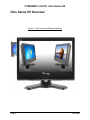
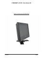
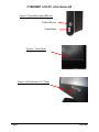
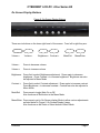
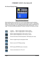
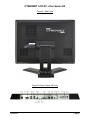
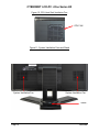
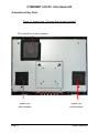
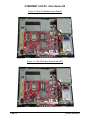
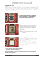
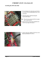
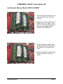
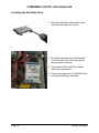
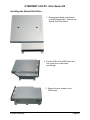
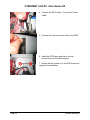
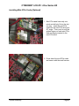
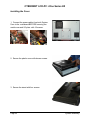
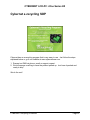
LCD-PC i-One Series H5 User Guide CYBERNET LCD-PC i-One Series H5 2 CYBERNET LCD-PC i-One Series H5 FCC-B Radio Frequency Interference Statement This equipment has been tested and found to comply with the limits for a class B digital device, pursuant to part 15 of the FCC rules. These limits are designed to provide reasonable protection against harmful interference in a residential installation. This equipment generates, uses and can radiate radio frequency energy and, if not installed and used in accordance with the instruction manual, may cause harmful interference to radio communications. However, there is no guarantee that interference will not occur in a particular installation. If this equipment does cause harmful interference to radio or television reception, which can be determined by turning the equipment off and on, the user is encouraged to try to correct the interference by one or more of the measures listed below. Reorient or relocate the receiving antenna. Increase the distance between the equipment and receiver. Connect the equipment into an outlet on a circuit different from that to which the receiver is connected. Consult the dealer or an experienced radio/television technician for help. Notice 1 The changes or modifications not expressly approved by the party responsible for compliance could void the user's authority to operate the equipment. Notice 2 Shielded interface cables and A.C. power cord, if any, must be used in order to comply with the emission limits. Trademarks All trademarks are the properties of their respective owners. Intel® is a registered trademark of Intel Corporation. Windows® 7/Vista/XP/NT/2000/98/95 are registered trademarks of Microsoft Corporation. Award® is a registered trademark of Phoenix Technologies Ltd. AMI® is a registered trademark of American Megatrends Inc. i CYBERNET LCD-PC i-One Series H5 Safety Instructions Always read the safety instructions carefully. Keep this equipment away from humidity. Lay this equipment on a reliable flat surface before setting it up. The openings on the enclosure are for air convection hence protect the equipment from overheating. DO NOT COVER THE OPENINGS. Confirm the voltage of the power source and adjust accordingly to 110/220V before connecting the equipment to the power inlet. Place the power cord in such a way that it cannot be stepped on. Do not place anything over the power cord. Always unplug the Power Cord before inserting any add-on card or module. All cautions and warnings on the equipment should be noted. Never pour any liquid onto the equipment. This will cause damage and/or electrical shock. Do not disable the protective grounding pin from the plug. The equipment must be connected to a grounded main socket/outlet. The Optical Storage devices are classified as Class 1 Laser products. Use of controls or adjustments or performance of procedures other than those specified is prohibited. Do not touch the Laser lens inside the optical storage drive. When installing the coaxial cable to the TV Tuner, it is necessary to ensure that the metal shield is reliably connected to a protective earthing system of the building. Cable distribution systems should be grounded (earthed) in accordance with ANSI/NF PA 70, the National Electrical Code (NEC ), in particular, Section 820.93, Grounding of Outer Conductive Shield of a Coaxial Cable. If any of the following situations arise, have the equipment checked by authorized service personnel: The power cord or plug is damaged. Liquid has penetrated into the equipment. The equipment has been exposed to moisture. The equipment has not worked well or does not work according to the User's Guide. The equipment has been dropped and damaged. The equipment has obvious signs of breakage. DO NOT LEAVE THIS EQUIPMENT IN AN UNCONDITIONED ENVIRONMENT WITH A STORAGE TEMPERATURE ABOVE 50° C (122°F). IT MAY DAMAGE THE EQUIPMENT. CAUTION: Danger of explosion if battery is incorrectly replaced. Replace only with the same or equivalent type recommended by the manufacturer. ii CYBERNET LCD-PC i-One Series H5 WEEE Statement (Waste Electrical and Electronic Equipment) The WEEE directive places an obligation on EU-based manufacturers, distributors, retailers and importers to take-back electronics products at the end of their useful life. A sister Directive, ROHS (Restriction of Hazardous Substances) compliments the WEEE Directive by banning the presence of specific hazardous substances in the products at the design phase. The WEEE Directive covers products imported into the EU as of August 13, 2005. EU-based manufacturers, distributors, retailers and importers are obliged to finance the costs of recovery from municipal collection points, reuse, and recycling of specified percentages per the WEEE requirements. Instructions for disposal of WEEE by Users in the European Union The symbol shown below is on the product or on its packaging, which indicates that this product must not be disposed of with other waste. Instead, it is the user‟s responsibility to dispose of their waste equipment by handing it over to a designated collection point for the recycling of waste electrical and electronic equipment. The separate collection and recycling of your waste equipment at the time of disposal will help to conserve natural resources and ensure that it is recycled in a manner that protects human health and the environment. For more information about where you can drop off your waste equipment for recycling, please contact your local city office, your household waste disposal service or where you purchased the product. iii CYBERNET LCD-PC i-One Series H5 TABLE OF CONTENTS FCC-B RADIO FREQUENCY INTERFERENCE STATEMENT .............................................................................................. I TRADEMARKS ............................................................................................................................................................ I SAFETY INSTRUCTIONS ............................................................................................................................................. II WEEE STATEMENT ................................................................................................................................................... III INTRODUCTION ........................................................................................................................................................ 1 I-ONE SERIES H5 SPECIFICATIONS ............................................................................................................................. 1 CPU SUPPORT ................................................................................................................................................................. 1 MOTHERBOARD CORE LOGIC .............................................................................................................................................. 1 MEMORY SUPPORT ........................................................................................................................................................... 1 OPTICAL DRIVE AND HDD SUPPORT ................................................................................................................................. 1 LCD DISPLAY ................................................................................................................................................................... 1 VIDEO & GRAPHICS FOR H5................................................................................................................................................ 1 VIDEO & GRAPHICS FOR IONE-H5G ..................................................................................................................................... 1 NETWORKING .................................................................................................................................................................. 2 AUDIO ............................................................................................................................................................................ 2 HARD DISK DRIVE ............................................................................................................................................................. 2 OPTICAL DRIVE................................................................................................................................................................. 2 WALL MOUNTING ............................................................................................................................................................ 2 SWIVEL BASE ................................................................................................................................................................... 2 EXPANSION SLOTS............................................................................................................................................................. 2 POWER SUPPLY ................................................................................................................................................................ 2 DIMENSIONS .................................................................................................................................................................... 2 WEIGHT .......................................................................................................................................................................... 2 SECURITY LOCK................................................................................................................................................................. 2 OPERATING ENVIRONMENT ................................................................................................................................................ 3 RELATIVE HUMIDITY .......................................................................................................................................................... 3 OPERATING SYSTEM COMPLIANCE ....................................................................................................................................... 3 SYSTEM BIOS .................................................................................................................................................................. 3 I/O PORTS BY LOCATION ........................................................................................................................................... 3 FRONT LOWER RIGHT BEZEL ............................................................................................................................................... 3 RIGHT SIDE BEZEL ............................................................................................................................................................. 3 LEFT SIDE BEZEL ............................................................................................................................................................... 3 BOTTOM I/O PANEL ......................................................................................................................................................... 3 IONE SERIES H5 OVERVIEW ....................................................................................................................................... 4 ON SCREEN DISPLAY BUTTONS ............................................................................................................................................ 7 ON SCREEN DISPLAY USAGE................................................................................................................................................ 8 SYSTEM ASSEMBLY ................................................................................................................................................. 11 NECESSARY TOOLS .......................................................................................................................................................... 11 ORIENTATION OF KEY PARTS ............................................................................................................................................. 12 IONE SERIES H5 DISASSEMBLY .......................................................................................................................................... 13 INSTALLING THE CPU....................................................................................................................................................... 15 INSTALLING THE CPU HEAT SINK ....................................................................................................................................... 16 INSTALLING THE MEMORY MODULE DDR3-SO-DIMM ........................................................................................................ 17 INSTALLING THE HARD DISK DRIVE ..................................................................................................................................... 18 iv CYBERNET LCD-PC i-One Series H5 INSTALLING THE OPTICAL DISK DRIVE .................................................................................................................................. 19 INSTALLING MINI-PCIE CARDS (OPTIONAL) ......................................................................................................................... 21 INSTALLING THE COVER .................................................................................................................................................... 22 CYBERNET E-RECYCLING SOP .................................................................................................................................. 25 Figures FIGURE 1: FRONT VIEW WITH OPTIONAL WEBCAM .................................................................................................. 4 FIGURE 2: LEFT SIDE VIEW WITH OPTICAL DRIVE ...................................................................................................... 5 FIGURE 3: POWER BUTTON AND USB PORTS ............................................................................................................ 6 FIGURE 4: TOUCH PANEL .......................................................................................................................................... 6 FIGURE 5: IRDA RECEIVER FOR TV TUNER ................................................................................................................. 6 FIGURE 6: ON SCREEN DISPLAY BUTTONS ................................................................................................................. 7 FIGURE 7: ON SCREEN DISPLAY ICONS ...................................................................................................................... 8 FIGURE 8: BACK VIEW .............................................................................................................................................. 9 FIGURE 9: BOTTOM PANEL I/O PORTS ...................................................................................................................... 9 FIGURE 10: CPU HEAT SINK VENTILATION FAN........................................................................................................ 10 FIGURE 11: SYSTEM VENTILATION FANS AND STAND ............................................................................................. 10 FIGURE 12: SYSTEM FANS, CPU HEAT SINK FAN AND VENTILATION ....................................................................... 12 FIGURE 13: IONE H5 STANDARD OPEN SYSTEM ...................................................................................................... 14 FIGURE 14: IONE H5G OPEN SYSTEM WITH GPU .................................................................................................... 14 v CYBERNET LCD-PC i-One Series H5 Introduction Congratulations for purchasing the i-One H5. The i-One Series H5 is your best Slim LCD PC choice. With the fantastic appearance and small form factor, it can easily be set anywhere. The feature packed platform also gives you an exciting PC experience. i-One Series H5 Specifications CPU Support Intel® Core™ i3, i5 and i7 Clarkdale & Lynnfield CPUs up to 1333MHz FSB in an LGA1156 package up to 95W. Motherboard Core Logic Intel® Nehalem PCH H55 chipset. Memory Support DDR3 1066/1333 MHz, PC3-10600 SO-DIMM SDRAM (Un-buffered Non-ECC) 2 x slots DDR3 1333 MHz SO-DIMM (8GB Max). OPTICAL DRIVE and HDD Support One SATA2 slot supports an internal HDD One SATA2 slot supports a slim optical DVD+/-RW, Blu-ray drive. One SATA2 port on the motherboard will support an additional device Integrated Serial ATA controller for high-speed transfers at up to 3Gbps for each port LCD Display 20” or 18.5” Wide TFT LCD Screen 16:9 format Video & Graphics for H5 Intel® integrated H55 Chipset with Intel® HD Graphics Intel GMA HD/Intel Clear Video HD Technology Built-in support for 1080p high-definition video playback, including Blu-ray disc movies 3D graphics performance Supports Microsoft® DirectX 10, Shader Model 4.0 and OpenGL 2.1. DVMT allocated as needed from 128MB to 1.70GB Maximum display resolution 2560 x 1600. Video & Graphics for iOne-H5G Onboard ATI5730 Madison-XT (M2) GPU 1.0GB DDR3/GDDR3 RAM 1080p HD video playback Supports Microsoft® DirectX 11, Shader Model 5.0 and OpenGL 3.2 Maximum display resolution 2560 x 1600. Specifications Page 1 CYBERNET LCD-PC i-One Series H5 Networking 2 LAN ports, 1Gb (GbE) Fast Ethernet, using Realtek RTL 8111E. Audio HD Audio Codec Realtek® AL889 Flexible 10-channel audio with jack sensing 2 internal stereo speakers, 2.5W, 78dB+/-3dB 3 audio jacks: 1 Audio Out, 1 Line-in, 1 Microphone Compliant with Azalia 1.0 Spec Hard Disk Drive One 2.5” SATA/SATA2 Hard Disk Drive - Any Capacity Supports Ultra DMA 66/100 mode Optical Drive 1 Slim Type Optical drive, DVD+/-RW, Blu-ray Wall Mounting Supports 75x75mm & 100x100mm VESA mounting holes Swivel Base System Base enables left/right rotation up to 60 degrees. tilt from -5 to 60 degrees Expansion Slots 2 mini-PCIe (1 x Full-size & 1 x Half-size) Power Supply 180 Watt Power Adapter AC Input: universal 100~240V AC, 2.5A, 50-60Hz DC Output: 12V/19V, 15.0A/9.5A Adapter: Energy Star 5.0/UL Dual mode power On/Off button for low power sleep mode Dimensions 491 mm (H) x 258.5 mm (W) x 460.5 mm (D) (with stand) Weight Unit: 22.9 lbs with base, 17.0 lbs without base Power Adapter: 2.2 lbs. Security Lock Lock slot located on the back of the system case Page 2 Specifications CYBERNET LCD-PC i-One Series H5 Operating Environment Ambient Temperature: 0 C ~ 50C (operating) Relative Humidity 10% ~ 90% (non-condensing) Operating System Compliance Microsoft Windows 7, Windows XP, LINUX System BIOS Award Flash BIOS supports ACPI, API, DMI, Plug & Play and Security Password Boots from HDD, PXE, LAN, CD-ROM and any USB device BIOS System POST and BIOS setup password protection TCG/TPM version 1.2 support I/O PORTS BY LOCATION Front Lower Right Bezel On Screen Display Buttons Volume Adjust Brightness Adjust Contrast Adjust Mute/Exit Menu/Enter Right Side Bezel 1 power button 2 USB 2.0 ports (for mouse and keyboard) Left Side Bezel 1 optical disk drive – 2.5” slim Bottom I/O Panel 1 DC/IN port 1 Serial RS-232 port 1 DVI-I port 2 LAN RJ-45 ports 4 USB 2.0 ports 3 Audio jacks – Line in, Line Out and Mic 4 TV Tuner ports -- Optional with TV Tuner (COAX Cable In, RCA Composite Video In, Audio Left & Audio Right) 1 clear CMOS button 1 system RESET button Specifications Page 3 CYBERNET LCD-PC i-One Series H5 iOne Series H5 Overview Figure 1: Front View with Optional Webcam Page 4 Overview CYBERNET LCD-PC i-One Series H5 Figure 2: Left side view with Optical Drive Overview Page 5 CYBERNET LCD-PC i-One Series H5 Figure 3: Power Button and USB Ports 2 Side USB ports Power Button Figure 4: Touch Panel Figure 5: IrDA Receiver for TV Tuner Page 6 Overview CYBERNET LCD-PC i-One Series H5 On Screen Display Buttons Figure 6: On Screen Display Buttons There are six buttons on the lower right bezel of the screen. From left to right they are: Volume – Volume + Brightness – Contrast + Volume - Press to decrease volume. Volume + Press to increase volume. Mute/Exit Menu/Enter Brightness- Press first to select Brightness adjustment. Press again to decrease brightness. Press Contrast + to increase brightness. Brightness can also be adjusted in Menu Mode. Contrast + Press first to select Contrast adjustment. Press again to increase contrast. Press Brightness – to decrease contrast. Contrast can also be adjusted in Menu Mode. Mute/Exit Press once to toggle Mute On or Off. Also functions as Exit button in the Menu Mode. Menu/Enter Press once to get to On-Screen display Mode to allow various adjustments as listed below in Figure 6, On Screen Display Usage. Also functions as the Enter or Select button in Menu Mode. Overview Page 7 CYBERNET LCD-PC i-One Series H5 On Screen Display Usage Figure 7: On Screen Display Icons When the Menu button is pressed, the on-screen display appears as pictured above. When in Menu Mode you can move to the various icons with the – (left) or + (right) button. When you are at the icon you wish to adjust, press Menu again (Enter) to change the color of the icon and then toggle your desired adjustment by again pressing either – (left) or + (right). The screen will exit automatically in a matter of seconds if no selection is made. Contrast Brightness Select to toggle greater or lesser contrast. Select to toggle greater or lesser brightness. Select to adjust the appearance of the screen to “Cool”. Select to adjust the appearance of the screen to “Warm”. Screen Horizontal and Vertical adjustment, OSD display time setup. Select to toggle through the languages offered. Select to reset all LCD Display settings OSD Firmware EEPROM version information. Screen mode selection for 16:9 or 4:3 Page 8 Overview CYBERNET LCD-PC i-One Series H5 Figure 8: Back View Figure 9: Bottom Panel I/O Ports Overview Page 9 CYBERNET LCD-PC i-One Series H5 Figure 10: CPU Heat Sink Ventilation Fan CPU FAN Figure 11: System Ventilation Fans and Stand System Ventilation Fan System Ventilation Fan Stand Page 10 Overview CYBERNET LCD-PC i-One Series H5 System Assembly This chapter provides system assembly information and procedures. While performing any installation, use a grounded wrist strap before handling computer components and carefully follow all installation procedures. Static electricity may damage the components. This chapter will include instructions for how to install CPU, heat sink, memory modules, hard disk drive (HDD), optical disk drive (ODD), and mini-PCIe card. Necessary Tools A Phillips screwdriver can be used to do most of the installation. One with a magnetic head is recommended. Applied maximum torque is 5kg. Pliers can be used as an auxiliary tool to connect some connectors or cables. Forceps/tweezers can be used to pick up tiny screws or set up the jumpers. Rubber gloves can prevent injury from static charge. Electric screwdriver can be used to secure all screws more quickly. System Assembly Page 11 CYBERNET LCD-PC i-One Series H5 Orientation of Key Parts Figure 12: System Fans, CPU Heat Sink Fan and Ventilation CPU Heat Sink Fan and Ventilation System Fan And Ventilation Page 12 System Fan And Ventilation System Assembly CYBERNET LCD-PC i-One Series H5 iOne Series H5 Disassembly ORIENTATION: Presumes the top of the iOne is away from you and the bottom or I/O controller board is nearest you. Place the iOne face down on a padded surface. Remove the four screws from the base plate that attaches the stand to the LCD supporting the base while removing the last screw. Remove the eleven back bezel screws. Carefully remove the back bezel and set aside. Then remove the metal EMI shield by first removing the I/O cover by removing the three screws on the bottom and four screws on the face. Lift the plate out and up and set aside. Remove the remaining eleven screws around the metal shield covering the motherboard. First lift the metal shield and slide it to the right clearing the optical drive door (at the top right) then disconnect the system fan cable connector from the motherboard at CPU FAN1 next to the top right corner of the CPU. System Assembly Page 13 CYBERNET LCD-PC i-One Series H5 Figure 13: iOne H5 Standard Open System Figure 14: iOne H5G Open System with GPU Page 14 System Assembly CYBERNET LCD-PC i-One Series H5 Installing the CPU NOTE: If you purchased your iOne Series H5 as a turn-key system, you must first follow the instructions to remove the heat sink in order to be able to reach the CPU. Systems purchased as „bare bones‟ require the installation of the heat sink which is shipped in the accessories box with the unit. 1. The socket has a plastic cap on it to protect the pins from damage. This should remain in place until actually installing a CPU. 2. Raise the plastic cap to reveal the socket pins and open the cover by pushing down, pulling out and up on the lever beside the CPU socket. Note: Do not touch the socket pins to avoid damage. 3. Install the CPU after confirming the direction for correct mating. Be sure to hold the CPU by the edge of the CPU base. Note: The CPU can only be installed in the correct direction. Make sure the CPU pins are completely embedded into the socket. If not, take out the CPU with vertical motion and reinstall. 4. Close the cover and the lever to complete installation. Replace the heat sink. NOTE: Any violation of the correct installation procedures may cause permanent damage to your mainboard. System Assembly Page 15 CYBERNET LCD-PC i-One Series H5 Installing the CPU Heat Sink 1. Put on the heat sink and make sure that the six screws fit the corresponding holes on the mainboard. 2. Alternate pressure while securing the screws with balance. Note: Do not fix any screws until all six screws are in their positions. 3. Secure the two screws at the opposite end near the top edge of the bezel. 4. Connect the power cable to CPU Fan on the Mainboard labeled CPU FAN 1. Page 16 System Assembly CYBERNET LCD-PC i-One Series H5 Installing the Memory Module DDR3-SO-DIMM 1. The memory module has only one notch and will only fit in the slot one way. 2. Insert the memory module into the DIMM slot at a 45° angle. Then, push it in until the golden finger on the memory module is deeply inserted in the DIMM slot. 3. Press the memory module down and the metal clip at each side of the DIMM slot will automatically close. 4. Repeat the steps to install another memory module to meet your needs. System Assembly Page 17 CYBERNET LCD-PC i-One Series H5 Installing the Hard Disk Drive 1. Mount the brackets to both sides of the hard disk drive with four screws 2. Mount the hard disk drive in the bracket onto the frame of the unit lining up and securing the four screws. 3. Connect the SATA cable & the Power cable to the mainboard. 4. Connect the other end of the SATA/Power to the hard Disk Drive as shown. Page 18 System Assembly CYBERNET LCD-PC i-One Series H5 Installing the Optical Disk Drive 1. Remove back bezel as indicated in iONE Disassembly. Remove the Optical Disk Drive frame. 2. Put the ODD on the ODD frame and line up the four screw holes accordingly. 3. Secure the four screws on the ODD frame. System Assembly Page 19 CYBERNET LCD-PC i-One Series H5 4. Connect the SATA cable. Connect the Power Cable. 5. Connect the other end of the cable to the ODD. 6. Install the ODD frame and line up the two screw holes over the Metal support. 7. Secure the two screws to fix the ODD frame and complete the installation. Page 20 System Assembly CYBERNET LCD-PC i-One Series H5 Installing Mini-PCIe Cards (Optional) 1. Mini-PCIe cards have only one notch and will only fit into the slot one way. Insert the mini-PCIe cards into the mini-PCIe slots at a 45° angle. Then, push in until the golden fingers on each mini-PCIe card are deeply inserted in the mini-PCIe slots. 2. Press down the mini-PCIe cards and secure with the small screws System Assembly Page 21 CYBERNET LCD-PC i-One Series H5 Installing the Cover 1. Connect the power cables from both System Fans to the mainboard BEFORE securing the metal cover and I/O plate with 18 screws. 2. Secure the plastic cover with eleven screws. 3. Secure the stand with four screws. Page 22 System Assembly CYBERNET LCD-PC i-One Series H5 System Assembly Page 23 CYBERNET LCD-PC i-One Series H5 Page 24 System Assembly CYBERNET LCD-PC i-One Series H5 Cybernet e-recycling SOP Cybernet has an e-recycling program that is very easy to use. Just follow the steps explained below or go to our website at www.cybernetman.com. 1. Request an RMA via phone, email or support request. 2. We will arrange a call tag to have the product picked up. Just have it packed and ready to ship. We do the rest! CYBERNET Recycling Procedure Page 25