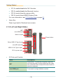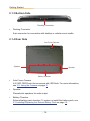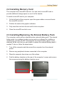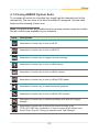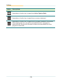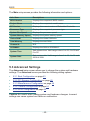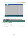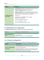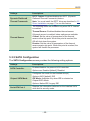
1
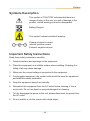
Gladius G0975 9.7” Intel® Celeron® N2930 Rugged Tablet PC User's Manual Version 1.0 P/N: 4019097500100P 2014.09 This page is intentionally left blank. - II - Revision History Version Date Descriptions 1.0 2014.09 Initial release -i- Copyright Copyright © 2014 ARBOR Technology Corp. All Rights Reserved. This document contains proprietary information protected by copyright. No part of this manual may be reproduced by any mechanical, electronic, or other means in any form without prior written permission of the manufacturer. Disclaimer The information in this document is subject to change without prior notice in order to improve the reliability, design and function. It does not represent a commitment on the part of the manufacturer. Under no circumstances will the manufacturer be liable for any direct, indirect, special, incidental, or consequential damages arising from the use or inability to use the product or documentation, even if advised of the possibility of such damages. About This Manual This user’s manual provides the general information and installation instructions for the product. The manual is meant for the experienced users and integrators with hardware knowledge of personal computers. If you are not sure about any description in this manual, consult your vendor before further handling. We recommend that you keep one copy of this manual for the quick reference for any necessary maintenance in the future. Thank you for choosing ARBOR products. - ii - Contents Contents Preface...........................................................................................................v Declaration of Conformity.......................................................................................v CE....................................................................................................................v FCC Class B....................................................................................................v RoHS..............................................................................................................vi SVHC / REACH..............................................................................................vi Symbols Description............................................................................................. vii Important Safety Instructions................................................................................ vii Rechargeable Battery Pack Safety........................................................................ix General Cleaning Tips............................................................................................x Cleaning Tools................................................................................................xi Recommended Cleaning Procedures.............................................................xi Disposing of the Computer................................................................................... xii Additional Information & Technical Support......................................................... xiii Warranty.............................................................................................................. xiv Chapter 1. Introduction.................................................................................1 1.1 Product Highlights............................................................................................2 1.2 Package Contents............................................................................................3 1.2.1 Order Information....................................................................................3 1.2.2 Configure-to-Order Service.....................................................................3 1.3 Specifications...................................................................................................4 1.4 Dimensions.......................................................................................................7 Chapter 2. Getting Started............................................................................9 2.1 Getting to Know the Computer.......................................................................10 2.1.1 Front Side.............................................................................................10 2.1.2 Left and Right Sides.............................................................................12 2.1.3 Bottom Side..........................................................................................14 2.1.4 Rear Side..............................................................................................14 2.2 Installing Memory Card...................................................................................15 2.3 Installing/Replacing the Extenal Battery Pack................................................15 2.4 Charging the Battery Pack..............................................................................17 2.5 Driver Installation............................................................................................17 Chapter 3. Using the Computer..................................................................21 3.1 Using Touch Screen........................................................................................22 3.1.1 Projected Capacitive Touch.................................................................22 3.1.2 Text Input..............................................................................................22 - iii - Contents 3.1.2.1 On-screen Keyboard............................................................22 3.1.2.2 Handwriting Recognition......................................................23 3.2 Function Keys.................................................................................................24 3.2.1 Using the Function Keys.......................................................................24 3.2.2 Customizing the Function Keys............................................................24 3.3 Using the Wi-Fi Feature..................................................................................26 3.4 Using the Bluetooth Feature...........................................................................28 3.4.1 Launching the Bluetooth Feature..........................................................28 3.4.2 Pairing/Connecting with Other Bluetooth Devices................................29 3.4.3 Bluetooth Device Name........................................................................30 3.4.4 Hiding/Exposing the Computer.............................................................30 3.5. Using the Camera..........................................................................................32 3.5.1 Launching the Camera.........................................................................32 3.5.2 Taking a Picture....................................................................................33 3.5.3 Shooting a Video...................................................................................33 3.5.4 Configuring Video Shooting..................................................................33 Chapter 4. Utilities.......................................................................................35 4.1 ARBOR System Suite.....................................................................................36 4.1.2 Accessing ARBOR System Suite..........................................................36 4.1.3 Using ARBOR System Suite.................................................................37 Chapter 5. BIOS...........................................................................................39 5.1 Accessing the BIOS Setup Utility....................................................................40 5.2 Main Setup.....................................................................................................41 5.3 Advanced Settings..........................................................................................42 5.3.1 Boot Configuration................................................................................43 5.3.2 PCI Express Configuration...................................................................43 5.3.3 Miscellaneous Configuration.................................................................44 5.3.4 Thermal Configuration .........................................................................44 5.3.5 SATA Configuration ..............................................................................45 5.4 Security Settings.............................................................................................46 5.5 Power Settings ..............................................................................................47 5.6 Boot Settings..................................................................................................48 5.7 Exit Options....................................................................................................49 - iv - Preface Preface Declaration of Conformity CE The CE symbol on your product indicates that it is in compliance with the directives of the Union European (EU). A Certificate of Compliance is available by contacting Technical Support. This product has passed the CE test for environmental specifications when shielded cables are used for external wiring. We recommend the use of shielded cables. This kind of cable is available from ARBOR. Please contact your local supplier for ordering information. FCC Class B This device complies with Part 15 of the FCC Rules. Operation is subject to the following two conditions: 1. This device may not cause harmful interference, and 2. This device must accept any interference received, including interference that may cause undesired operation. Any changes or modifications not expressly approved by the guarantee of this device could void the user’s authority to operate the equipment. This equipment has been tested and found to comply with the limits for a Class B digital device, pursuant to Part 15 of the FCC Rules. These limits are designed to provide reasonable protection against harmful interference in a residential installation. This equipment generates, uses and can radiate radio frequency energy and, if not installed and used in accordance with the instructions, may cause harmful interference to radio communications. However, there is no guarantee that interference will not occur in a particular installation. If this equipment does cause harmful interference to radio or television reception, which can be determined by turning the equipment off and on, the user is encouraged to try to correct the interference by one or more of the following measures: • • Reorient or relocate the receiving antenna. • • Increase the separation between the equipment and receiver. -v- Preface • • Connect the equipment into an outlet on a circuit different from that to which the receiver is connected. • • Consult the dealer or an experienced radio/TV technician for help. RoHS ARBOR Technology Corp. certifies that all components in its products are in compliance and conform to the European Union’s Restriction of Use of Hazardous Substances in Electrical and Electronic Equipment (RoHS) Directive 2002/95/EC. The above mentioned directive was published on 2/13/2003. The main purpose of the directive is to prohibit the use of lead, mercury, cadmium, hexavalent chromium, polybrominated biphenyls (PBB), and polybrominated diphenyl ethers (PBDE) in electrical and electronic products. Member states of the EU are to enforce by 7/1/2006. ARBOR Technology Corp. hereby states that the listed products do not contain unintentional additions of lead, mercury, hex chrome, PBB or PBDB that exceed a maximum concentration value of 0.1% by weight or for cadmium exceed 0.01% by weight, per homogenous material. Homogenous material is defined as a substance or mixture of substances with uniform composition (such as solders, resins, plating, etc.). Lead-free solder is used for all terminations (Sn(96-96.5%), Ag(3.0-3.5%) and Cu(0.5%)). SVHC / REACH To minimize the environmental impact and take more responsibility to the earth we live, ARBOR hereby confirms all products comply with the restriction of SVHC (Substances of Very High Concern) in (EC) 1907/2006 (REACH --Registration, Evaluation, Authorization, and Restriction of Chemicals) regulated by the European Union. All substances listed in SVHC < 0.1 % by weight (1000 ppm) - vi - Preface Symbols Description This symbol of “CAUTION” indicates that there is a danger of injury to the user or a risk of damage to the product, should warning notices be disregarded. Battery Recycle This symbol indicates electrical warning. Change of electric current: Internal: positive current External: negative current Important Safety Instructions Read these safety instructions carefully: 1. Read all cautions and warnings on the equipment. 2. Place this equipment on a reliable surface when installing. Dropping it or letting it fall may cause damage. 3. Make sure the correct voltage is connected to the equipment. 4. For pluggable equipment, the socket outlet should be near the equipment and should be easily accessible. 5. Keep this equipment away from humidity. 6. Disconnect this equipment from the A/C outlet before cleaning it. Use a moist cloth. Do not use liquid or sprayed detergent for cleaning. 7. To fully disengage the power to the unit, please disconnect the power from the AC outlet. 8. Do not scratch or rub the screen with a hard object. - vii - Preface 9. Never use any of the solvents, such as Thinner Spray-type cleaner, Wax, Benzene, Abrasive cleaner, Acid or Alkaline solvent, on the display. Harsh chemicals may cause damage to the cabinet and the touch sensor. 10.Remove dirt with a lightly moistened cloth and a mild solvent detergent. Then wipe the cabinet with a soft dry cloth. 11. The openings on the enclosure are for air convection and protect the equipment from overheating. DO NOT COVER THE OPENINGS. 12. Position the power cord so that people cannot step on it. Do not place anything over the power cord. 13. If the equipment will not be used for a long time, disconnect it from the power source to avoid damage by transient overvoltage. 14. Never pour any liquid into openings. This may cause fire or electrical shock. 15. Never open the equipment. For safety reasons, the equipment should be opened only by qualified service personnel. 16. If one of the following situations arises, get the equipment checked by service personnel: a. The power cord or plug is damaged. b. Liquid has penetrated into the equipment. c. The equipment has been exposed to moisture. d. The equipment does not work well, or you cannot get it to work according to the user’s manual. e. The equipment has been dropped or damaged. f. The equipment has obvious signs of breakage. 17. The sound pressure level at the operator’s position, according to IEC 7041:1982, is no more than 70dB(A). 18. Keep this User’s Manual for later reference. 19. DO NOT LEAVE THIS EQUIPMENT IN AN UNCONTROLLED ENVIRONMENT WHERE THE STORAGE TEMPERATURE IS BELOW - viii - Preface -20° C (-4° F) OR ABOVE 60° C (140° F). THIS MAY DAMAGE THE EQUIPMENT. Rechargeable Battery Pack Safety • • Important Terms to Understand “Battery life” means the time the equipment will run before it must be recharged (sometimes this is also called “playtime” or “runtime”). “Battery lifespan” means the total amount of time your battery will last before it must be replaced. • • Using the Equipment for the First Time Be sure to fully charge (approx. 4 hours) the equipment when charging the equipment for the first time. • • Long-Term Storage & Maintenance If you are putting away the battery for more than three months, it is recommended that the battery should be stored separately and fully charged, and get recharged every three months. If you store an uncharged battery, it could fall into a deep worn-out state which would render it incapable of holding any charge. Be sure to store the equipment and battery at the proper temperature. • • Battery Lifespan The removable batteries for the equipment are designed to retain up to 80% of their original capacity after 300 charging and recharging cycles when properly maintained. You may choose to purchase new battery when it no longer holds the sufficient charge that meets your needs. • • The lithium-ion battery is currently one of the most popular battery packs. The best advantage is that it has no memory effect, so users needn’t worry about that issue. Users can charge the battery anytime whether it is fully drained or not. However, it’s recommended that users drain the battery until the system shows power shortage warning and then recharge the battery. Doing so is helpful to the reliability of your battery. • • Don’t use the battery pack as a power supply for other equipment. • • Don’t expose the battery to elevated heat situations such as under direct sunlight in a car or near fire. - ix - Preface • • Don’t disassemble the battery, or the battery leakage might cause skin or eye injury. If electrolyte leaking from the battery contacts your skin or clothing, immediately flush it with running water. If it splashes into eye, rinse the eye at least 15 minutes with clean water and then seek medical attention. • • To avoid battery leakage or explosion, don’t discard the battery into water or fire, or put them near a heat source such as a gas stove or an oven. • • If you are putting away the battery for more than three months, it is recommended that the battery should be stored separately and fully charged, and get recharged every three months. If you store an uncharged battery, it could fall into a deep worn-out state which would render it incapable of holding any charge. Be sure to store your the equipment and battery at the proper temperature. • • Use the appropriate container to store the battery such as a paper box. Do not allow a metal object to touch the terminal of the battery. • • The battery consists of precise electrical components and cells. Do not drop or hit the battery. General Cleaning Tips You may need the following precautions before you begin to clean the device. When you clean any single part or component for the device, please thoroughly read and understand the details below. 1. We strongly recommended that you should shut down the system before you start to clean any single components. 2. When you need to clean the device, please rub it with a piece of dry cloth. 3. Be cautious of the tiny removable components when you use a vacuum cleaner to absorb the dirt on the floor. 4. Never drop the components inside the device or get circuit board damp or wet. 5. Be cautious of all kinds of cleaning solvents or chemicals when you use it for the sake of cleaning. Some individuals may be allergic to the ingredients. 6. Try not to put any food, drink or cigarette around the device. -x- Preface Cleaning Tools Although many companies have created products to help improve the process of cleaning your devices and peripherals, users can also use household items to clean their devices and peripherals. Below is a listing of items you may need or want to use while cleaning your devices or peripherals. Keep in mind that some components in your device may only be able to be cleaned using a product designed for cleaning that component, if this is the case it will be mentioned in the cleaning. • Cloth: A piece of cloth is the best tool to use when rubbing up a component. Although paper towels or tissues can be used on most hardware as well, we still recommend you to rub it with a piece of cloth. • Water or rubbing alcohol: You may moisten a piece of cloth a bit with some water or rubbing alcohol and rub it on the device. Unknown solvents may be harmful to the plastics parts. • Vacuum cleaner: Absorb the dust, dirt, hair, cigarette particles, and other particles out of the device can be one of the best cleaning methods. Over time, these items can restrict the airflow in a device and cause circuitry to corrode. • Cotton swabs: Cotton swaps moistened with rubbing alcohol or water are excellent tools for wiping hard to reach areas in your keyboard, mouse, and other locations. • Foam swabs: Whenever possible, it is better to use lint-free swabs such as foam swabs. Recommended Cleaning Procedures 1. Close all application programs 2. Close operating software 3. Turn off power switch 4. Remove all peripherals 5. Pull out power cable - xi - Preface Disposing of the Computer • • Within the European Union EU-wide legislation, as implemented in each Member State, requires that waste electrical and electronic products carrying the mark (left) must be disposed of separately from normal household waste. This includes monitors and electrical accessories, such as signal cables or power cords. When you need to dispose of your display products, please follow the guidance of your local authority, or ask the shop where you purchased the product, or if applicable, follow any agreements made between yourself. The mark on electrical and electronic products only applies to the current European Union Member States. • • Outside the European Union If you wish to dispose of used electrical and electronic products outside the European Union, please contact your local authority so as to comply with the correct disposal method. - xii - Preface Additional Information & Technical Support All ARBOR products are built to the most accurate specifications to ensure reliable performance in the harsh and demanding conditions typical of industrial environments. Whether your new equipment is destined for the laboratory or the factory floor, you can be assured that the computer will provide the reliability and ease of operation. Your satisfaction is our primary concern. We want you to get the maximum performance from the computer. So if you run into technical difficulties, we are here to help. For the most frequently asked questions, you can easily find answers in the computer’s documentation. These answers are normally a lot more detailed than the ones we can give over the phone. So please consult this manual first. If you still cannot find the answer, gather all the information or questions that apply to your problem, and with the product close at hand, call your dealer. Our dealers are well trained and ready to give you the support you need to get the most from the computer. In fact, most problems reported are minor and are able to be easily solved over the phone. We are always ready to give advice on application requirements or specific information on the installation and operation of any of our products. Do not hesitate to contact us: Webite: http://www.arbor.com.tw E-mail: [email protected] TEL: 886-2-8226-9396 Add: 10F., No.700, Zhongzheng Rd., Zhonghe Dist., New Taipei City 235, Taiwan - xiii - Preface Warranty This product is warranted to be in good working order during the warranty period. Should this product fail to be in good working order at any time during this period, we will, at our option, replace or repair it at no additional charge except as set forth in the following terms. This warranty does not apply to products damaged by misuse, modifications, accident or disaster. Vendor assumes no liability for any damages, lost profits, lost savings or any other incidental or consequential damage resulting from the use, misuse of, or inability to use this product. Vendor will not be liable for any claim made by any other related party. Vendors disclaim all other warranties, either expressed or implied, including but not limited to implied warranties of merchantability and fitness for a particular purpose, with respect to the hardware, the accompanying product’s manual(s) and written materials, and any accompanying hardware. This limited warranty gives you specific legal rights. Return authorization must be obtained from the vendor before returned merchandise will be accepted. Authorization can be obtained by calling or faxing the vendor and requesting a Return Merchandise Authorization (RMA) number. Returned goods should always be accompanied by a clear problem description. - xiv - 1 Chapter 1 Introduction Chapter 1. Introduction -1- Introduction 1.1 Product Highlights The G0975 Series is a rugged mobile tablet PC featuring a compact 9.7” XGA IPS LED display and 5MP rear camera. Designed for mobile field applications, the G0975 Series weighs just 1.0 kg and integrates Wi-Fi and Bluetooth wireless connectivity for seamless wireless communication. Compliant with IP65 and MIL-STD-810G shock & vibration standard, the G0975 Series also comes with sealed I/O ports and sturdy rubber bumpers on each of its four corners for enhanced protection. Featuring slim design, high portability and long battery life, the G0975 Series is ideal for mobile POS and logistics application. • • 9.7” XGA IPS LED display with Projected Capacitive Touch • • High computing performance from Intel® Quad Core Celeron® • • Fully rugged for mobile POS or warehousing application • • Meeting MIL-STD-810G, IP65, 4 ft. drop resistance • • High mobility, multiple connectivity (Bluetooth/WLAN/WWAN) • • Adopting multi-touch Screen with Corning® Gorilla® Glass • • Supporting external battery with battery cover and internal battery • • Providing four function keys and home key • • Providing system security -2- Introduction 1.2 Package Contents Upon opening the package, carefully inspect the contents. If any of the items is missing or appears damaged, contact your local dealer or distributor. The package should contain the following items: 1 x G0975 Computer 1 x Driver CD 1 x User’s Manual 19V/3.42A 65W AC/DC Adapter Kit 2270mAh External Battery Pack 1.2.1 Order Information G0975 9.7” Intel® Celeron® N2930 rugged tablet PC with XGA LCD, projected capacitive touch, battery pack, WLAN, Bluetooth and Rear Camera G0975S 9.7” Intel® Celeron® N2930 rugged tablet PC with XGA LCD, projected capacitive touch, battery pack, WLAN and Bluetooth, Rear Camera, and sunlight readable display (700 nits) 1.2.2 Configure-to-Order Service Make the computer more tailored to your needs by selecting one or more components from the list below to be fabricated to the computer. IBAT-0975 2270mAh 2-cell Internal Battery Pack -3- Introduction 1.3 Specifications System CPU Intel® Celeron® Processor N2930 quad-core 1.83 GHz Graphics Controller Intel® HD Graphics Memory 2GB DDR3L SO-DIMM memory module installed (optional up to 8GB) BIOS UEFI BIOS 1 x integrated microphone Audio 2 x piezoelectric speaker 1 x 3.5 mm headset combo jack Storage 1 x 32GB MLC mSATA SSD Peripherals and Devices WLAN Integrated WLAN 802.11 a/b/g/n Bluetooth Integrated Bluetooth 4.0 BLE, class 2 Camera 5.0 MP rear CMOS camera with Auto Focus and light supplement Sensor Accelerometer, Magnetometer, Gyroscope & Light Sensor I/O Interface USB Port 1 x USB 3.0/2.0 Type-A port 1 x Micro USB 2.0 Type-A port SD Card 1 x microSD/SDHC/SDXC slot HDMI 1 x mini-HDMI 1.4 port Docking Port 1 x 8-pin docking connector Reset 1 x reset button Button & Indicator Function Keys Power Button 1 x Home key 4 x Function keys 1 x Power on/off button 1 x Power LED LED Indicators 1 x Battery LED 1 x WLAN LED 1 x Bluetooth LED -4- Introduction Touch Screen Type 10-point Projected Capacitive Touch w/ Corning® Gorilla® Glass Light Transparency 80% (typ.) Controller Interface USB Interface LCD Display Size/Type 9.7” XGA IPS LED Display Max. Resolution 1024x768 (XGA), w/ 262,144 Colors Luminance 350 cd/m² (typ.) Contrast Ratio 500 : 1 View Angle (U/D/R/L) 89°/89°/89°/89° Backlight Type LED Power Supply Adapter Input 100 ~ 240VAC (Full Range) Adapter Output 19VDC, 3.42A, 65W Battery Type Li-battery pack Battery Capacity Battery Life 1 x 2270mAh 4-cell external battery pack 1 x 2270mAh 2-cell internal battery pack (Optional) Up to 8 hours (depends on configuration and use) Mechanical & Environmental Operating Temp. -20 ~ 45ºC (-4 ~ 113ºF) Storage Temp. -20 ~ 60ºC (-4 ~ 140ºF) Charging Temp. 0 ~ 40ºC (32 ~ 104ºF) Operating Humidity 10 ~ 95% @ 45ºC (non-condensing) Dimensions (W x D x H) 258 x 198 x 22.5 mm (10.04" x 7.80" x 0.89") Gross Weight 1.0 kg (2.20 lb) w/o 2-cell internal battery pack 20 to 1000 Hz @ 1 grms per MIL-STD 810G (operating) Vibration 20 to 1000 Hz @ 3 grms per MIL-STD 810G (nonoperating) 11 ms @ 20G per MIL-STD 810G for unit only (operating) Shock 11 ms @ 40G per MIL-STD 810G for unit only (nonoperating) -5- Introduction Transit Drop 1.2m (4ft.) per MIL-STD-810G for whole unit IP Rating IP65 Regulatory CE EN55022 class B FCC 47 CFR, Part 2 and Part 15 OS Support Windows Embedded 7 / Windows 7 Professional Windows 8.1 Embedded Standard / Windows 8.1 Embedded Industry / Windows 8.1 Embedded Professional Ordering Information G0975 9.7” Intel® Celeron® N2930 rugged tablet PC with XGA LCD, projected capacitive touch, battery pack, WLAN, Bluetooth and rear camera G0975S 9.7” Intel® Celeron® N2930 rugged tablet PC with XGA LCD, projected capacitive touch, battery pack, WLAN and Bluetooth, rear camera, and sunlight readable display (700 nits) -6- Introduction 1.4 Dimensions 260.21 258 30.6 A 24 197.95 200.26 22.5 A Unit:mm -7- This page is intentionally left blank. -8- 2 Chapter 2 Getting Started Chapter 2. Getting Started -9- Getting Started 2.1 Getting to Know the Computer 2.1.1 Front Side Power status LED Microphone Battery status LED Wi-Fi LED Bluetooth LED Home Key Function keys Touch screen • • Microphone The built-in microphone captures sound and voice when used with a program capable of recording audio. • • Touch Screen The computer comes with a 10-point projected capacitive touch screen allowing users to interact with the computer without a mouse or keyboard. See 3.1 Using Touch Screen on page 22 to know how to do the touch control and text input on a touch screen. - 10 - Getting Started • • Status LED Icon LED Power Color Green Status Descriptions On The computer is in main power mode. Blinking The computer is in sleep mode. Off No power is present. The battery is not charged. On Current battery level: 50% ~ 100%. Green Blinking *Current battery level: 16% ~ 49%. Orange Blinking Blinking Green Bluetooth Blue Current battery level: 16% ~ 49%. *Current battery level: 0% ~ 15%. Red Wi-Fi Battery charge is in process. The battery is not charged. On N/A *Current battery level:50% ~ 99% The battery is not charged On Battery Battery charge is in process. Battery charge is in process. *Current battery level: 0% ~ 15%. Off No battery is present. On The Wi-Fi is enabled. Off The Wi-Fi is disabled. On The Bluetooth is enabled. Off The Bluetooth is disabled. * The battery level is an average between the batteries present to the computer. • • Function Keys Four functions keys are available enabling you to quickly execute certain programs or functions. If you didn’t install the ARBOR System Suite, then the functions of these keys are defined by Windows system. For example, F1 is used to launch Help and F2 is to rename a selected file or folder. Once you installed the ARBOR System Suite, the keys will be associated with most commonly used features such as Wi-Fi or Bluetooth. The default function of each key is as below: - 11 - Getting Started • • F1: To enable/disable the Wi-Fi function. • • F2: To enable/disable the Bluetooth function. • • F3: To launch/close the camera utility. • • F4: To launch/close ARBOR System Suite. For more information, see 3.2 Function Keys on page 24. • • Home Key Press to go back to Windows home screen. 2.1.2 Left and Right Sides RST mini-HDMI port Audio out jack Power button Micro USB 2.0 Type-A port microSD card slot USB 2.0/3.0 Type-A port DC-In power jack • • I/O Ports and Controls Items Descriptions RST Reset button. To reset the computer, insert the end of a paperclip or similar object into the reset hole. Press and then release the button inside to reset the computer. mini-HDMI port To connect to a high-definition monitor. - 12 - Getting Started Items Descriptions Audio out 3.5mm combo audio/microphone jack. To connect to a set of headphones or speakers. Micro USB 2.0 Type-A port To connect to a USB device. To insert a microSDXC/SDHC/SD card. microSD card slot When inserting the card, make sure to position the card as the graphic indicates, and fully insert the card into the slot until it cannot be inserted any more. To connect to a USB device. USB 3.0/2.0 Type-A port DC-In power jack For Windows 7, make sure to install USB 3.0 driver on the provided CD. To connect to the power adapter to provide power to the computer or to charge the battery. • • Power Button Use the Power Button to power on/off the computer, or to put the computer to Sleep or Hibernation mode. Refer to the following table for control options. Control Operations To power on the computer Press-and-hold the Power Button until the power LED lights green. To put the computer into the sleep state Press (without holding) the Power Button. To wake the computer from the sleep state Press (without holding) the Power Button. To resume the computer from hibernation state Press-and-hold the Power Button until the power LED lights green. - 13 - Getting Started 2.1.3 Bottom Side Docking Connector • • Docking Connector 8-pin connector for connection with desktop or vehicle-mount cradle. 2.1.4 Rear Side Auto Focus Camera Speaker Speaker Battery Chamber • • Auto Focus Camera A 5.0 MP CMOS auto-focus camera with LED flash. For more information, see 3.5. Using the Camera on page 32. • • Speaker Piezoelectric speakers for audio output. • • Battery Chamber External battery pack chamber. To replace or install the battery pack, see 2.3 Installing/Replacing the Extenal Battery Pack on page 15. - 14 - Getting Started 2.2 Installing Memory Card The computer has a microSD card slot. You can insert a microSD card to provide additional storage space or use it for file transfer. To install a microSD card to your computer: 1. On the left side of the computer, open the upper rubber cover and locate the microSD card slot. 2. Position the card as the graphic indicates. 3. Fully insert the card into the slot until it clicks into place. 4. Close the microSD card slot cover. 2.3 Installing/Replacing the Extenal Battery Pack The computer comes with an internal and an external battery pack. The internal battery pack is a configue-to-order service and is not allowed for installing or replacing by yourself. Do NOT disassemble the internal battery pack or your warranty will be void. But you can install or replace the external battery pack if needed. To do so, follow the steps below: 1. Turn off the computer and disconnect the computer from the external power. 2. Remove any peripheral devices connected to the computer. 3. Place the computer face-down on a flat surface. 4. Find the battery chamber on the rear of the computer. Loosen and remove the screws securing the battery chamber cover. - 15 - 5. The inside of the battery chamber comes to view. Power connector 6. Find the power connector for the external battery inside the battery chamber as illustrated above. To remove an existing external battery, disconnect the battery’s power cable first and then remove the battery. To install a new external battery, plug the battery’s power cable to the power connector first. 7. Fit the battery into the chamber and restore the chamber cover. 8. Secure the cover with the screws you removed in Step 4. - 16 - 2.4 Charging the Battery Pack To recharge the battery inside the computer: 1. Connect the power adapter to the computer’s power jack and a power source. You can find power adapter & cord in the accessory box. 2. The battery LED indicator ( ) blinks to indicate that charging is in progress. The battery LED color changes according the battery level as described in the Status LED section in 2.1.1 Front Side on page 10. When the battery is fully charged, the battery LED indicator lights solid green. When charging the battery, note that: • • The battery will be fully charged within 3-4 hours (depending on the capacity of the battery). When charging finishes, it’s recommended to remove the adapter from the computer. • • It’s recommended not to recharge intermittently, which means not to plug and unplug the power adapter frequently in a short period of time. • • Do not use the power adapter that is not made for your computer. Supplying the computer with inappropriate voltage may cause harm to the battery or, even worse, burn the computer. • • The lithium-ion battery is currently one of the most popular battery pack. The best advantage is that it has no memory effect, so users needn’t worry about that issue. Users can charge the battery anytime whether it is fully drained or not. However, it’s recommended that users drain the battery until the system shows power shortage warning and then recharge the battery. Doing so is helpful to the reliability of your battery. • Don’t use the battery pack as a power supply for other equipment. 2.5 Driver Installation The computer comes with a CD that contains device drivers as well as some programs and utilities. You need to install the drivers to activate the devices and some device-related services. Some drivers will come with driver-related programs to facilitate the application. To install the drivers and utilities, make sure to follow the instructions (e.g., the installation sequence) given in this section to proceed. - 17 - In addition, the CD includes a number of optional utilities. You may install those utilities as needed. See the table below for the CD-DOM content and the driver needed to be installed for the computer: Driver Type Necessity Descriptions Chipset Required TXE Required Install the Intel Trusted Execution Engine and Trusted Connect Service to enable Intel Trusted Execution Engine Interface. Graphic 64/32bit Required Install the graphics driver. Select 64 or 32-bit according to your operating system. DPTF Required Install the Intel Dynamic Platform and Thermal Framework component. MBI Required Install the driver for Intel Sideband Fabric Device Driver (Intel MBI). Wi-Fi Required Install the Wi-Fi driver and application. Bluetooth Required Install the Bluetooth driver and application. Audio Required Install the audio driver and application. Touch Screen No need The computer’s capacitive touch screen is ready to use. No need to install the touch screen driver. Function Keys Recommended Install the ARBOR System Suite to associate a function key with a specific feature or application program. Power Saving AP Optional Install the power saving application. USB Required for Win7 For Windows 7, install the USB driver to use the USB 3.0 interface. Install the chipset driver to the computer. Make sure to install the chipset driver before installing other device drivers to prevent errors. To install the drivers: 1. Connect a USB CD-ROM drive (not provided) to the computer. According to your CD-ROM drive, you may need to connect it to a power supply. - 18 - 2. Insert the provided CD to the CD-ROM drive. In a few seconds, a dialog box opens asking what to do with the disc. Tap Run AUTORUN.EXE to auto-run the driver CD. 3. Tap Win7 Driver Install or Win8 Driver Install according to your operating system. If you want to browse the CD contents, tap Browse CD instead. 4. The drivers menu then opens. Tap Chipset to install the chipset driver first. Caution: Make sure to install the chipset driver first before installing other device drivers or otherwise errors may occur. - 19 - Make sure to install the chipset driver first. 5. Follow the on-screen instructions to proceed. 6. After installing the chipset drivers, proceed to install the remaining drivers, including TXE, Graphic, DPTF, MBI, Wi-Fi, Bluetooth and Audio. When installing the remaining drivers, there is no need to follow any specific order. The installation process of each driver is basically the same. Just follow the on-screen instructions to proceed. - 20 - 3 Chapter 3 Using the Computer Chapter 3. Using the Computer - 21 - Using the Computer 3.1 Using Touch Screen The computer comes with a projected capacitive touch screen. Touch control is the main way and an intuitive way to interact with the computer. Users are able to manipulate icons, graphic buttons, menus, property sheets, the on-screen keyboard or any on-screen items with touch control. This chapter will walk you through the basic operations for touch control. 3.1.1 Projected Capacitive Touch Unlike the resistive touch, the projected capacitive touch works by the change of capacitance when a conductive object, such as a finger, contact the touch screen. Hence it requires only a human finger and zero force to trigger actions from the projected capacitive touch screen. And no calibration is needed. If the computer runs Windows 7/8, the projected capacitive touch screen is ready to function when the computer is delivered. No driver is needed. 3.1.2 Text Input The computer doesn't have a physical keyboard to receive user's text input. To input text on the computer, it relies on either an external USB keyboard, or the "on-screen keyboard", or the Windows-featured handwriting recognition. 3.1.2.1 On-screen Keyboard An "on-screen keyboard" is a virtual keyboard with all the standard keys. With Windows you can use either a touch keyboard or thumb keyboard to facilitate text input. To open the Windows on-screen keyboard: 1. Tap the keyboard icon on the Windows taskbar. 2. The Input Panel opens in either keyboard mode or handwriting mode, according to your previous use. Tap the icon in the lower right corner to switch between the modes. - 22 - Using the Computer The thumb keyboard The touch keyboard The handwriting panel Exit the on-screen keyboard 3. To use the touch or thumb keyboard, just enter text by tapping the keys. 3.1.2.2 Handwriting Recognition “Handwriting Recognition” is an input method that interprets and converts handwriting to text. The Windows features a “writing pad” to get the job done. To launch the Windows handwriting panel: 1. Tap the keyboard icon on the Windows taskbar to open the Input Panel as described in 3.1.2.2 Handwriting Recognition on page 23. If it’s in keyboard mode, tap the icon in the lower right corner and tap the handwriting icon to switch to handwriting mode. - 23 - Using the Computer 2. Write in the writing area. Then tap the bottom-right Enter button to enter the text in a text field. 3.2 Function Keys 3.2.1 Using the Function Keys The computer comes with four function keys enabling you to quickly execute certain programs or functions. If you didn’t install the ARBOR System Suite, a function key association program available in the provided CD (see 2.5 Driver Installation on page 17), then the functions of these keys are defined by Windows system. For example, F1 is used to launch Help and F2 is to rename a seleted file or folder. Once you installed the ARBOR System Suite, by default the keys will be associated with most commonly used features such as Wi-Fi or Bluetooth as below: • • F1: To enable/disable Wi-Fi function. • • F2: To enable/disable Bluetooth function. • • F3: To launch/close the camera utility. • • F4: To launch/close ARBOR System Suite. 3.2.2 Customizing the Function Keys With the ARBOR System Suite installed on your computer, you can re-define the function keys according to your requirement. To do so: 1. Tap the ARBOR System Suite shortcut - 24 - in the notification area. Using the Computer ARBOR System Suite shortcut in the notification area 2. The ARBOR System Suite then opens on-screen. For the key that you want to reassign a function, simply tap the intended function. Assigned function will be highlighted in blue. Function key assignment panel Status bar For more information on using the ARBOR System Suite, see 4.1 ARBOR System Suite on page 36. - 25 - Using the Computer 3.3 Using the Wi-Fi Feature The computer is built-in with a Wi-Fi module for Wi-Fi networking. Once the driver is installed as described in 2.5 Driver Installation on page 17, a Wi-Fi signal strength icon shows up in the notification area. Wi-Fi icon in the notification area The following descriptions assume that you have installed the ARBOR System Suite to use the function key. Follow the guide below to connect the computer to a Wi-Fi hotspot: 1. Launch the Wi-Fi module by hitting the function key (F1 by default). The system shows the Wi-Fi status in the bottom right corner of the screen. Hitting the function key will toggle on/off the Wi-Fi function. When Wi-Fi is enabled, the function icon is highlighted in blue or otherwise dimmed. Wi-Fi enabled Wi-Fi disabled When Wi-Fi is enabled, the Wi-Fi signal strength icon in Windows notification area also changes from to . Wi-Fi disabled The computer is connected to a wireless network Wi-Fi enabled and there are available wireless networks in range - 26 - Using the Computer Note: If you didn’t install the ARBOR System Suite and want to launch the Wi-Fi function, please refer to Windows online help on how to turn on Wi-Fi. 2. Tap the Wi-Fi signal strength icon in the notification area. 3. A list opens and shows the Wi-Fi hotspots available within the wireless coverage of the computer. 4. Tap the desired network to connect it. If the network to connect is a secured network, a dialog will open and request for the password. Enter the password to access the Wi-Fi network. If it is an open network, it will be connected in a few seconds. 5. When the computer is connected to a Wi-Fi network, “Connected” will be displayed and the Wi-Fi signal strength icon in the notification area changes to . Note: To conserve power, always turn off the Wi-Fi module when it isn’t used. - 27 - Using the Computer 3.4 Using the Bluetooth Feature Bluetooth enables the wireless connection over a short distance about 8 meters. It is specified as a “wireless personal area network” (WPAN). The computer is Bluetooth-enabled to synchronize data with other Bluetoothcapable devices such as PCs, laptops, hands-free, headsets, printers, PDAs and cell phones. Once the Bluetooth driver is installed as described in 2.5 Driver Installation on page 17, you can start to use the Bluetooth function. The following descriptions assume that you have installed the ARBOR System Suite to use the function key. Follow the guide below to proceed. 3.4.1 Launching the Bluetooth Feature To be able to use Bluetooth, launch the Bluetooth module first: 1. Launch the Bluetooth module by hitting the function key (F2 by default). The system shows the Bluetooth status in the bottom right corner of the screen. Hitting the function key will toggle on/off the Bluetooth function. When Bluetooth is enabled, the function icon is highlighted in blue or otherwise dimmed. Bluetooth enabled Bluetooth disabled When Bluetooth is enabled, a Bluetooth icon shows up in the notification area, meaning the Bluetooth module is activated. - 28 - Using the Computer Note: To conserve power, always power off the Bluetooth module when it isn’t used. 3.4.2 Pairing/Connecting with Other Bluetooth Devices Before the computer can connect with other Bluetooth devices, it has to pair with them. To pair/connect with other Bluetooth devices: 1. Launch the Bluetooth module as described in 3.4.1 Launching the Bluetooth Feature on page 28. 2. From the notification area, tap the Bluetooth icon . 3. A context menu opens. Select Add a Device from the context menu that opens. 4. An Add a device window opens. Select the Bluetooth device to connect and follow the on-screen instructions to proceed. - 29 - Using the Computer 3.4.3 Bluetooth Device Name By default, the computer’s Bluetooth device name is the computer name that is viewable at Control Panel | System and Security | System. 3.4.4 Hiding/Exposing the Computer By default, the computer is NOT discoverable by other Bluetooth devices. To hide or expose the computer: 1. Launch the Bluetooth module as described in 3.4.1 Launching the Bluetooth Feature on page 28. 2. From the notification area, tap the Bluetooth icon - 30 - . Using the Computer 3. A context menu opens. Select Open Settings from the context menu. 4. The Bluetooth Settings dialog box then opens. Tap the Options tab and find the Discovery section. To make your computer discoverable to Bluetooth enabled devices, select the check box of Allow Bluetooth devices to find this computer or otherwise deselect the check box to make it undiscoverable. - 31 - Using the Computer 3.5. Using the Camera The computer comes with a ready-to-use camera without the need to install additional drivers. You can use the camera to take pictures or videos. 3.5.1 Launching the Camera To launch the camera: 1. Assign a function key to launch the camera module. 2. Launch the camera module by hitting the function key. The system shows the camera status in the bottom right corner of the screen. Hitting the function key will toggle on/off the camera function. When camera is launched, the function icon is highlighted in blue or otherwise dimmed. Camera enabled Camera disabled After you launch the camera module, a camera program will automatically open in a few seconds. Subject scene Enables/mutes shutter audio Tool bar Video Shooting Settings Closes camera program Takes a picture Shoots a video - 32 - Using the Computer 3.5.2 Taking a Picture To take a picture: 1. Launch the camera as described in 3.5.1 Launching the Camera on page 32. The camera program automatically launches. 2. From the camera application program’s tool bar, tap the take-a-picture icon . The camera then proceeds to take a picture and save it to local disk (by default at C:\) | Users | (your username) | My Documents | ccd.) 3.5.3 Shooting a Video To shoot a video: 1. Launch the camera (also the camcorder) as described in 3.5.1 Launching the Camera on page 32. The camera program automatically launches. 2. From the camera application program’s tool bar, tap the shoot-a-video icon . The starts. icon then changes to an in-shoot button 3. Tap the in-shoot button , and video shooting again to stop shooting. The video shot is saved to local disk (by default at C:\) | Users | (your username) | My Documents | ccd.) 3.5.4 Configuring Video Shooting To configure the video shooting: 1. Launch the camera (also the camcorder) as described in 3.5.1 Launching the Camera on page 32. - 33 - Using the Computer The camera program automatically launches. 2. From the camera program’s tool bar, tap the configuration icon . The Properties dialog box opens. 3. Make the configuration as needed. 4. Tap the Apply button to apply the changes. Tap the OK button to save the changes and exit the dialog box. Or tap the Cancel button to quit the changes and exit the dialog box. - 34 - 4 Chapter 4 Utilities Chapter 4. Utilities - 35 - Utilities 4.1 ARBOR System Suite The Arbor System Suite is a utility to control the computer’s physical function keys F1 through F4. With this ARBOR System Suite, users can associate a function key to turn on/off one of the computer’s features or to launch a specific application program installed on the computer. 4.1.2 Accessing ARBOR System Suite With the Arbor System Suite installed on your computer, tap the Arbor System Suite shortcut System Suite. in the notification area to launch and use Arbor The ARBOR System Suite then opens on-screen. Function key assignment panel Status bar • • Function key assignment panel The icons indicate the features/programs you can assign to a function key. For which feature/program the icon indicates, see next section. Assigned features/programs are highlighted in blue. • • Status bar Indicates the on/off status of various functions. When a function is on, its icon is highlighted in blue. - 36 - Utilities 4.1.3 Using ARBOR System Suite To re-assign a function to a function key, simply tap the intended icon for the desired key. The icon turns to be blue to indicate it’s assigned. See the table below for the meaning of each icon. Note: The panel shows all possible functions across various computer models. Not all functions are available in your computer. Icons Descriptions Associates a function key to turn on/off 3G. Associates a function key to turn on/off Wi-Fi. Associates a function key to trigger barcode scanning. Associates a function key to turn on/off Bluetooth. Associates a function key to turn on/off the camera. Associates a function key to turn on/off the RFID reader. Associates a function key to enable/mute the speakers. Associates a function key to turn on/off the GPS module. Associates a function key to show/hide battery level and Wi-Fi signal strength. Associates a function key to launch the screen brought up by CTRL+ALT+DEL key combination. It open a screen which shows Lock, Switch User, Sign out, Change a password and Task Manager. - 37 - Utilities Icons Descriptions Associates a function key to open/close Arbor System Suite. Associates a function key to open/close on-screen keyboard. Associates a function key to open/close a program installed in the system. When tapping the icon, you will be prompted to select a program to associate with. Browse the Windows to select the executable file of the program to associate. - 38 - 5 Chapter 5 BIOS Chapter 5. BIOS - 39 - BIOS A BIOS (Basic Input/Output System) is a special utility usually stored in the ROM on the motherboard inside a computer. When you turn on the computer, the BIOS is immediately activated. During the startup, it checks and loads necessary information to ensure the computer can proceed with loading the operating system. The BIOS Setup Utility is typically accessed with a special key sequence, such as “Delete” or “Esc” key as soon as the computer is powering up. Once you have entered the BIOS, you can get some system information and configure some hardware parameters. In most cases, there will be no need to make adjustments to the BIOS. The default settings apply to most applications and provide optimal performance. Caution: If you need to make any change, be careful when making changes to the BIOS. Incorrect settings can cause system boot failure or malfunction. NOTE: For system stability and performance, this BIOS utility is constantly improved. The screenshots demonstrated and descriptions hereinafter are for reference only and may not exactly meet what is presented on-screen. 5.1 Accessing the BIOS Setup Utility To enter and use the BIOS Setup Utility, prepare a USB keyboard first and then: 1. Connect the USB keyboard to the computer first. 2. Power on the computer and press the “Delete” or “Esc” key immediately after powering on. 3. Then you will enter the BIOS Setup Utility and see the Main setup screen. BIOS Setup Utility is mainly a key-based navigation interface. The bottom of the screen shows the keys for navigation and changing the settings. Refer to the table below for instructions on using the keys. Keys Descriptions F1 Activate “General Help” screen. ← → Move to select a particular configuration screen from the top menu bar / Move to highlight items on the screen. ↓ ↑ Move to select an item. - 40 - BIOS Keys Descriptions Enter Select or enter a submenu Esc On the Main Menu – Exit the setup and not save changes into CMOS. + / F6 Increase a numeric value. - / F5 Decrease a numeric value. F9 Load the optimal defaults. All settings will be set to the optimal defaults at startup. F10 Save the changes that have been made and exit the BIOS Setup Utility. On the Sub Menu – Exit current page and return to main menu. 5.2 Main Setup When you first enter the BIOS Setup Utility, you will enter the Main setup screen. It reports basic system information and also allows you to configure the System Date and System Time settings. Main Advanced Security Rev. 5.0 InsydeH20 Setup Utility Power Boot Exit BIOS Version G0975 1.00 This is the help for the hour, Project Name G0975 minute, second field. Valid EC Version 0.21 range is from 0 to 23, 0 to 59. Processor Type System Bus Speed System Memory Speed Cache RAM Total Memory Channal A SODIMM0 Intel(R) Celeron(R) CPU N2930 @1.83GHz 83 MHz 1333 MHz 1024 KB 2048 MB INCREASE/REDUCE : +/-. 2048 MB System Time System Date [17:04:19] [08/02/2014] F1 Help Select Item F5/F6 Change Values F9 Setup Defaults ESC Exit Select Menu Enter Select SubMenu F10 Save and Exit - 41 - BIOS The Main setup screen provides the following information and options: Info / Item Descriptions BIOS Version Displays the computer’s BIOS version. Project Name Displays the computer’s model name. EC Version Displays the current version of Embedded Controller. Processor Type Displays the computer’s processor type. System Bus Speed Displays the processor speed. System Memory Speed Displays the system memory speed. Cache RAM Displays the cache RAM size. Total Memory Displays the total RAM. Channel A N/A. SODIMM 0 Displays the RAM of SODIMM 0. System Time Sets system time. Valid range is from 0 to 23, 0 to 59 and 0 to 59. System Date Sets system date. Valid range is from 1 to 12, 1 to 31 and 2000 to 2099. 5.3 Advanced Settings The Advanced setup screen allows you to change the system and hardware settings. The Advanced screen provides the following setting options: • • 5.3.1 Boot Configuration on page 43 • • 5.3.2 PCI Express Configuration on page 43 • • 5.3.3 Miscellaneous Configuration on page 44 • • 5.3.4 Thermal Configuration on page 44 • • 5.3.5 SATA Configuration on page 45 Caution: Be careful when making system and hardware changes. Incorrect settings can cause system boot failure or malfunction. - 42 - BIOS Main Advanced Security Rev. 5.0 InsydeH20 Setup Utility Power Boot Exit Configures Boot Settings. Boot Configuration PCI Express Configuration Miscellaneous Configuration Thermal Configuration SATA Configuration F1 Help Select Item F5/F6 Change Values F9 Setup Defaults ESC Exit Select Menu Enter Select SubMenu F10 Save and Exit 5.3.1 Boot Configuration The Boot Configuration screen provides the following setting options: Settings Descriptions Numlock Turns on/off the Num Luck key function when the computer is in power-on state. 5.3.2 PCI Express Configuration The PCI Express Configuration screen provides the following setting options: - 43 - BIOS Settings Descriptions XX PCI Express Root Port: Enables/disables this PCIe port. XX PCIE Port Speed: Select the PCIe port speed. Options are: Auto [default], Gen 1, Gen 2 XX PCI Express Root Port 1/2/3/4 PCIE Port ASPM: Select an ASPM (Active-State Power Management) mode to manage the PCI Express serial link devices in order to reduce power consumption. Options are: Auto [default] : allow BIOS to auto configure Disabled : disable ASPM L0s : force all links to L0s state L1 : force all links to L1 state L0sL1 : force all links to L0s+L1 state 5.3.3 Miscellaneous Configuration The Miscellaneous screen provides the following setting options: Settings Restore AC Power Loss Description / Available Options Specify what state to go to when power is re-applied after a power failure. Options are: Power on, Power off [default] 5.3.4 Thermal Configuration The Thermal Configuration screen provides the following setting options: Settings Thermal Configuration Parameters Descriptions Critical Trip Point: Set the value of temperature of the ACPI critical trip point. When this point is reached, the OS will shut down the system. Passive Trip Point: Set the value of temperature of the ACPI passive trip point. When this point is reached, the OS will begin to throttle the processor. - 44 - BIOS Settings Dynamic Platform& Thermal Framework Descriptions DPTF Feature: Enables/disables the DPTF (Dynamic Platform&Thermal Framework) feature. Note: You must install the DPTF driver as described in 2.5 Driver Installation on page 17 to use this feature. The following items are available only when DPTF feature is enabled. Thermal Sensor: Enables/disables thermal sensor. If thermal sensor is enabled, below options are available: Thermal Sensor Critical: Set the value of temperature of the thermal sensor critical trip point. When this point is reached, the OS will shut down the system. Passive: Set the value of temperature of the thermal sensor passive trip point. When this point is reached, the system will throttle the processor. 5.3.5 SATA Configuration The SATA Configuration screen provides the following setting options: Settings SATA Controller Descriptions Enables/disables the present SATA controller. Options are: Enabled [default], Disabled Configures the mode for the installed drive(s). Options: AHCI [default], IDE Chipset SATA Mode IDE Mode: Available only when IDE is selected as Chipset SATA Mode. Options: Native IDE, Legacy IDE Serial ATA Port 0 Displays the information detected on the installed SATA drive and its security mode. - 45 - BIOS 5.4 Security Settings The Security setup screen allows you to configure BIOS security settings to keep unauthorized people from making any changes to the BIOS. Main Advanced Security Rev. 5.0 InsydeH20 Setup Utility Power Boot Exit Supervisor Password Install or Change the password Not Installed and the length of password must be greater than one character. Set Supervisor Password F1 Help Select Item F5/F6 Change Values F9 Setup Defaults ESC Exit Select Menu Enter Select SubMenu F10 Save and Exit The Security screen provides the following setting options: Settings Descriptions To set up a supervisor password. Set Supervisor Password After selecting Set Supervisor Password, a dialog box then pops up on-screen. Enter and confirm your desired password. The length of the password must be greater than one character. To change an existing supervisor password, you will need to enter the original password. This item is available only when supervisor password is set. Power on Password Enables/disables power on password. If enabled, you will be prompted to enter the supervisor password on POST time. - 46 - BIOS 5.5 Power Settings The Power setup screen contains only one item “Advanced CPU Control” which allows you to configure the CPU power mode. Main Advanced Security Rev. 5.0 InsydeH20 Setup Utility Power Boot Exit These items control various Advanced CPU Control CPU parameters. F1 Help Select Item F5/F6 Change Values F9 Setup Defaults ESC Exit Select Menu Enter Select SubMenu F10 Save and Exit The Advance CPU control screen provides the following setting options: Settings Descriptions C-States Enables/disables processor idle power saving states (C-states). Enhanced C-States Enables/disables P-state transitions to occur in combination with C-states. Max C-States Set the Max CPC state. Options: C7 [default], C6, C1 - 47 - BIOS 5.6 Boot Settings The Boot menu configures how to boot up the system such as the configuration of boot device priority. Main Advanced Security Rev. 5.0 InsydeH20 Setup Utility Power Boot Exit Quick Boot Quiet Boot Timeout Allows InsydeH20 to skip certain <Enabled> <Enabled> [0] tests while booting. This will decrease the time needed to boot the system. Legacy F1 Help Select Item F5/F6 Change Values F9 Setup Defaults ESC Exit Select Menu Enter Select SubMenu F10 Save and Exit The Boot screen provides the following setting options: Settings Descriptions Quick Boot Allow InsydeH20 to skip certain tests while booting. This will decrease the time need to boot the system. Quiet Boot Disables or enables booting in text mode. Timeout Set the number of seconds that the firmware will wait before booting the original default boot selection. - 48 - BIOS Settings Descriptions Boot Device Priority Normal Boot Menu: Select a boot option priority. Options: Normal [default], Advance When Normal is selected, the following items are available: Legacy Boot type order: Change boot type order. Hard Disk Drive: Change hard disk drive. When Advance is selected, the hard disk drive info will be displayed. 5.7 Exit Options The Exit screen provides the options regarding saving changes, quitting the utility and recovering defaults. Main Advanced Security Rev. 5.0 InsydeH20 Setup Utility Power Boot Exit Exit Saving Changes Exit Discarding Changes Exit system setup and save your changes. Load Optimal Defaults F1 Help Select Item F5/F6 Change Values F9 Setup Defaults ESC Exit Select Menu Enter Select SubMenu F10 Save and Exit - 49 - BIOS The Exit screen provides the following options: Settings Descriptions Exit Saving Changes Save the changes and exit the BIOS Setup Utility. Exit Discard Changes Exit the BIOS Setup Utility without saving the change(s). Restores all settings to defaults. Load Optimal Defaults After selecting this item, a dialog box will pop up to confirm your choice. - 50 -