1
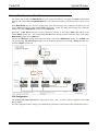
TurboVUi™ by CTI Products, Inc. System Planner For Version 5.x Software Document # S2-61645-500 TurboVUi System Planner Contact Information Support, replacement part ordering, and service may be arranged by contacting our Cincinnati office. Parts for service can be returned following request of a Return Material Authorization (RMA). CTI Products, Inc. 1211 W Sharon Rd Cincinnati, OH 45240 513-595-5900 [email protected] Disclaimer Information in this document is provided with best efforts for completeness and accuracy. However, no guarantee is expressed or implied, and details may change without notice. Revision History 500 May 31, 2012 Initial Release 2 TurboVUi System Planner Table of Contents INTRODUCTION – TURBOVUI SYSTEM OVERVIEW ..................................................................................................5 TURBOVUI COMPONENTS .......................................................................................................................................................5 ARCHITECTURE .......................................................................................................................................................................6 System Limitations .............................................................................................................................................................. 6 ENVIRONMENTAL CONSIDERATIONS .......................................................................................................................................7 RF Interference .................................................................................................................................................................. 7 Lightning and Fire Protection ............................................................................................................................................ 7 Power Requirements........................................................................................................................................................... 7 STATIC IP ADDRESS ................................................................................................................................................................7 TURBOVUI SYSTEM PLANNER TEMPLATE ..............................................................................................................................7 ACCESSING THE TURBOVUI IP GATEWAY USING PORT FORWARDING ...................................................................................7 LICENSING ..............................................................................................................................................................................8 TurboVUi Dispatch Clients ................................................................................................................................................ 8 TurboVUi Solo Clients and Pocket Apps ............................................................................................................................ 8 TURBOVUI VERSION MATCH..................................................................................................................................................8 WHAT IS INCLUDED ............................................................................................................................................................9 TURBOVUI IP GATEWAY KIT .................................................................................................................................................9 TURBOVUI DISPATCH CLIENT PACK ......................................................................................................................................9 OTHER ITEMS NEEDED .................................................................................................................................................... 10 MOTOTRBO XPR4550 CONTROL STATION RADIO............................................................................................................. 10 XPR4550 PROGRAMMING CABLE ......................................................................................................................................... 10 Laptop or PC .................................................................................................................................................................... 10 WINSJIPPTRBO PROGRAMMING UTILITY ............................................................................................................................ 10 DATA REVERT CABLE ........................................................................................................................................................... 10 CONFIGURATION AND INSTALLATION STEPS ......................................................................................................... 11 SYSTEM EXAMPLES .......................................................................................................................................................... 12 CONVENTIONAL DIGITAL OR ANALOG SYSTEM WITHOUT DATA REVERT ............................................................................. 12 CONVENTIONAL DIGITAL SYSTEM WITH DATA REVERT ....................................................................................................... 13 IP SITE CONNECT SYSTEM WITHOUT DATA REVERT ............................................................................................................. 14 IP SITE CONNECT SYSTEM WITH DATA REVERT ................................................................................................................... 15 CAPACITY PLUS SYSTEM WITHOUT DATA REVERT ............................................................................................................... 16 CAPACITY PLUS SYSTEM WITH DATA REVERT...................................................................................................................... 17 ARS AND GPS SIGNALING ................................................................................................................................................ 18 ARS SIGNALING ................................................................................................................................................................... 18 GPS SIGNALING .................................................................................................................................................................... 18 CONVENTIONAL DIGITAL SYSTEM WITHOUT DATA REVERT ................................................................................................. 19 CPS Configuration ........................................................................................................................................................... 19 CONVENTIONAL DIGITAL SYSTEM WITH DATA REVERT ....................................................................................................... 20 CPS Configuration ........................................................................................................................................................... 20 IP SITE CONNECT SYSTEM WITHOUT DATA REVERT ............................................................................................................. 21 CPS Configuration ........................................................................................................................................................... 21 IP SITE CONNECT SYSTEM WITH DATA REVERT ................................................................................................................... 22 CPS Configuration ........................................................................................................................................................... 22 CAPACITY PLUS SYSTEM WITHOUT DATA REVERT ............................................................................................................... 23 CPS Configuration ........................................................................................................................................................... 23 CAPACITY PLUS SYSTEM WITH DATA REVERT...................................................................................................................... 24 CPS Configuration ........................................................................................................................................................... 24 3 TurboVUi System Planner MOTOROLA ENHANCED GPS REPEATER OPTION .................................................................................................. 25 COMPARISON WITH STANDARD DATA REVERT ..................................................................................................................... 25 CONFIGURATION REQUIREMENTS ......................................................................................................................................... 25 TurboVUi IP Gateways .................................................................................................................................................... 25 MOTOTRBO™ Repeaters ................................................................................................................................................ 25 Subscriber Radios............................................................................................................................................................. 26 CPS CONFIGURATION TABLES ...................................................................................................................................... 27 SYSTEM DESIGN RESOURCES ........................................................................................................................................ 28 MOTOTRBO SYSTEM DESIGN TOOLS ................................................................................................................................. 28 TURBOVUI SYSTEM PLANNER TEMPLATE ............................................................................................................................ 28 APPENDIX ............................................................................................................................................................................. 29 APPENDIX - IP ADDRESSING.................................................................................................................................................. 29 APPENDIX - CONFIGURING PORT FORWARDING ON ROUTERS ............................................................................................... 29 APPENDIX – IP GATEWAY SPECIFICATIONS .......................................................................................................................... 30 Mechanical and Environmental ....................................................................................................................................... 30 Electrical .......................................................................................................................................................................... 30 Miscellaneous ................................................................................................................................................................... 30 APPENDIX - REFERENCE DOCUMENTS ................................................................................................................................... 31 APPENDIX - REPLACEMENT PARTS ........................................................................................................................................ 31 SYSTEM PLANNER TEMPLATE PAGE 1 OF 2 .......................................................................................................... 32 TURBOVUI IP GATEWAYS .................................................................................................................................................... 32 SYSTEM PLANNER TEMPLATE PAGE 2 OF 2 .......................................................................................................... 33 TURBOVUI DISPATCH CLIENTS ............................................................................................................................................ 33 TURBOVUI SOLO CLIENTS .................................................................................................................................................... 33 4 TurboVUi System Planner INTRODUCTION – TURBOVUI SYSTEM OVERVIEW TurboVUi™ provides remote access to MOTOTRBO radios via IP Networks. PC-based software allows voice communications between PC users and 2-way radio subscribers. Communications with radio subscribers is also possible for mobile users using Android or iOS devices. A TurboVUi system consists of at least one TurboVUi IP Gateway (server) and at least one client (Dispatch™, Solo™, or Pocket™) with an IP network connecting the TurboVUi components. TURBOVUI COMPONENTS The TurboVUi system is based on Server-Client architecture. The TurboVUi system components are described below: • TurboVUi IP Gateway Kit (CTI Part # S2-61528) This is hardware interface connects a MOTOTRBO XPR4550 control station radio to an IP network. The IP Gateway is the Server for the control station radios connected to it. Each control station radio used for voice requires one IP Gateway. A maximum of three additional control station radios used for GPS Data Revert may share the voice IP Gateway. TurboVUi system components, such as IP Gateways, may be located together or separated geographically and connected via a Wide Area Network (WAN) or Virtual Private Network (VPN). Each IP Gateway requires a static IP address. Each IP Gateway includes a cable to connect it to the XPR4550 Control Station radio. For more information, see the following documents: TurboVUi IP Gateway - Installation and Configuration Manual, Document # S2-61534 TurboVUi System Brochure • TurboVUi Dispatch™ Client (CTI Part # S1-61603) This dispatch console application for PCs provides voice dispatching to multiple simultaneous radio channels or talk groups. Other features include Texting, GPS Mapping of radio subscribers, and Voice Logging. Either Windows 7 Pro or Windows XP Pro operating system is required. TurboVUi system components, such as Dispatch Clients, may be located together or separated geographically and connected via a Wide Area Network (WAN) or Virtual Private Network (VPN). For more information, see the following information: TurboVUi Dispatch Software Installation Guide, Document # S2-61535 TurboVUi Dispatch User Guide, Document # S2-61577 TurboVUi System Brochure • TurboVUi Solo™ Client This software application for PCs provides voice dispatching to a single radio channel or talk group. It requires Windows 7 or Windows XP operating system. The virtual radio head duplicates the full functionality of a control station, including channel steering. Other features include Texting and Voice Logging for 24 hours. TurboVUi system components, such as Solo Clients, may be located together or separated geographically and connected via a Wide Area Network (WAN) or Virtual Private Network (VPN). For more information, see the following documents: TurboVUi Solo Client – Quick-Start Guide, Document # S2-61568 TurboVUi System Brochure • TurboVUi Pocket™ App for Android™ and iPhone™/iPad™ mobile devices A mobile app that is used for voice dispatching to a single radio channel or talk group. The virtual radio head duplicates the full functionality of a control station, including channel steering. Other features include Texting and GPS Mapping of radio subscribers. For more information, see the following documents: TurboVUi Pocket App Quick-Start Guide, Document # S2-61620 TurboVUi System Brochure • Control Station Radio A MOTOTRBO XPR4550 control station radio must be used as the interface to the radio system, and connects to a TurboVUi IP Gateway using the rear accessory port. Each control station radio used for voice requires one IP Gateway. A maximum of three additional control station radios used for GPS Data Revert may share a voice IP Gateway. 5 TurboVUi • System Planner Personal Computer or Workstation A PC or workstation is required to host the TurboVUi Dispatch client or TurboVUi Solo client. Console accessories may include microphone and speakers (or headset), Push-to-Talk footswitch, and touch screen monitor. ARCHITECTURE The IP Gateways interface the radio system to an IP network, ensuring easy wide-area deployment without configuring server PCs. One IP Gateway is required for each control station radio used for voice. The IP Gateways and control station radios can be centrally located or scattered among different locations using a Virtual Private Network (VPN) or Wide Area Network (WAN) such as the Internet. A system may have a mixture of TurboVUi Dispatch and TurboVUi Solo Clients, as well as TurboVUi Pocket apps running on mobile devices. Dispatch Clients, Solo Clients, and Pocket apps can be centrally located or scattered among different locations using a Virtual Private Network (VPN) or Wide Area Network (WAN) such as the Internet. System Limitations System limitations include the following: System Component Maximum Dispatch Clients 12 Simultaneous Solo Client and Pocket mobile app connections 36 IP Gateways 36 6 TurboVUi System Planner ENVIRONMENTAL CONSIDERATIONS The operating environment for the IP Gateway must be within limits noted in the specifications, as well as other conditions. Do not install equipment in an area where any of the following exist: • Extreme temperature and humidity beyond limits listed in the specifications • High EMI (Electro-Magnetic Interference) or RFI (Radio Frequency Interference) • High dust concentration • High ESD (Electrostatic Discharge) • Extreme Vibration RF Interference To prevent RF interference, Mobile radio antennas should be kept a minimum of 24 feet from the TurboVUi IP Gateway when in high-power mode, or a minimum of 12 feet when in low-power mode. Portable radios should be kept a minimum of 6 feet from the TurboVUi IP Gateway. Lightning and Fire Protection Lightning protection should be implemented at both the equipment and at the point of entry of the building. Lightning protection and power transient protection should be implemented to reduce the risk of fire caused by these phenomena. Circuit breakers and fuses offer the best methods for preventing extended over-current and over-voltage conditions. Power Requirements When using the supplied AC power adapter, each IP Gateway requires 100-240VAC, .25A maximum. When connecting a DC supply directly to the IP Gateway, each IP Gateway requires 11.5 – 12.5 VDC, 2.5A maximum. When the DC supply is a standard 13.8VDC used for battery recharging, use CTI’s Diode Dropping assembly (S2-61593) in series between the 13.8VDC power supply and the IP Gateway. STATIC IP ADDRESS Each TurboVUi IP Gateway requires a static IP address. The IP Gateway must have IP Network Parameters configured using ICU.exe (IP Configuration Utility) before connecting to an active network. Contact your IT administrator to provide a static IP Address for each TurboVUi IP Gateway, along with its Subnet Mask and Default Gateway. TURBOVUI SYSTEM PLANNER TEMPLATE Use the System Planner Template at the end of this document to record IP addresses, device names, and passwords. ACCESSING THE TURBOVUI IP GATEWAY USING PORT FORWARDING If TurboVUi clients (such as Solo, Dispatch, or Pocket) will access an IP Gateway from a different IP network, then the IT Administrator must configure port forwarding within the firewall or router that separates the TurboVUi IP Gateway from other networks. This is also true when one or more of the clients listed above will connect to a TurboVUi IP Gateway from the Internet. See section “Appendix - Configuring Port Forwarding on Routers” on Page 29 for more information. 7 TurboVUi System Planner LICENSING TurboVUi Dispatch Clients Each PC that runs the TurboVUi Dispatch client requires a USB hardware key and software license file. The USB hardware key contains an encrypted Serial Number. The license file with the same Serial Number specifies the number of IP Gateways that can be connected using TurboVUi Dispatch. The USB hardware key must remain installed in the PC when running TurboVUi Dispatch. Connections for additional IP Gateways can be purchased and added to the license file at any time. TurboVUi Solo Clients and Pocket Apps For client types other than TurboVUi Dispatch, a license file that is factory-installed on the IP Gateway allows connections from Solo clients (for PCs and Notebooks) and Pocket apps (for Android™ and iPhone™/iPad™). Each IP Gateway is shipped with a factory-installed license file allowing at least one connection. Additional connections can be purchased with IP Gateway, or can easily be added to an IP Gateway that is already installed. Single or five-pack connection add-ons can be purchased for the IP Gateway license file, up to a maximum of 36 connections. The number of connections purchased should be the maximum number of simultaneous connections from PCs running the Solo client, and mobile devices (Android™ and iPhone™/iPad™) running the Pocket app. The number of connections installed on the license file is indicated on the serial number label located on the bottom of the IP Gateway. The number of installed connections can also be determined from a connected TurboVUi Solo client if logged in using the “admin” username using the following steps: 1. From the Settings menu, choose Gateway. 2. In the TurboVUi Gateway Settings window, click the Admin tab. The “Client Licenses” parameter will show the number of purchased connections. TURBOVUI VERSION MATCH TurboVUi Software for the IP Gateway and Clients (Dispatch, Solo and Pocket for mobile devices) must all have compatible versions in order to communicate with each other. Compatibility occurs when the first two digits of the version are identical. (The third digit indicates a minor revision, and does not need to match.) 8 TurboVUi System Planner WHAT IS INCLUDED TURBOVUI IP GATEWAY KIT The TurboVUi IP Gateway Kit (Part # S2-61528) includes the following items: CTI Part # Description Notes S3-61530 TurboVUi IP Gateway Includes power supply, 100-240VAC to 12VDC S2-61534 Manual, TurboVUi IP Gateway Installation Guide Read me first S2-61568 Manual, TurboVUi Solo Client Quick-Start Guide Use only if Solo Client(s) to be installed S2-61620 Manual, TurboVUi Android Client Quick-Start Guide Use only if Android Client(s) to be installed S2-61565 CD, TurboVUi IP Gateway Contains ICU.exe, Solo Client Install Program, and manuals listed above S2-61431 Cable, Radio Interface for Audio and Control Interface cable between IP Gateway and XPR4550, for Audio and Control signals S2-60760 Cable, Cat 5 RJ45 Cross-over, 3 ft Used with ICU.exe during IP Gateway configuration 89-10712 Cable, Cat 5 RJ45, 10 ft Can be used to connect IP Gateway to LAN Note: ICU.exe is available on either of the following distribution CDs: • “TurboVUi IP Gateway”, Part Number S2-61565. This CD contains ICU.exe (executable file) that must be copied to a writeable disk before running. (ICU.exe cannot be run directly from non-writeable data storage such as the distribution CD.) • “TurboVUi Dispatch”, Part Number S2-61506. This CD contains an installer program that will install the TurboVUi Dispatch Client Software and ICU.exe onto the PC. Following the installation from the distribution CD, this utility can be located by clicking the Start menu button, then click on All Programs, then click on the TurboVUi Dispatch folder, then click TurboVUi ICU. TURBOVUI DISPATCH CLIENT PACK The TurboVUi Dispatch Client Pack (Part # S1-61603) includes the following items: CTI Part # Description Notes S3-61506 TurboVUi Dispatch Software CD S2-61529 TurboVUi Dispatch Serialized Software License CD Must match Serial Number of USB Key 90-11864 TurboVUi Dispatch USB Hardware Key Must match Serial Number of License CD S2-61535 Manual, TurboVUi Dispatch Software Installation Guide S2-61577 Manual, TurboVUi Dispatch User Guide 9 TurboVUi System Planner OTHER ITEMS NEEDED MOTOTRBO XPR4550 CONTROL STATION RADIO Each MOTOTRBO XPR4550 Control Station radio used for voice requires one IP Gateway. A maximum of three additional control station radios used for GPS Data Revert may share an IP Gateway. The MOTOTRBO XPR4550 must have firmware Version 1.6.x or later. XPR4550 PROGRAMMING CABLE A radio programming cable is required to configure the XPR4550 Control Station radio, subscriber radios, and repeaters. A programming cable connected to the front microphone connector on the XPR4550 will prevent communications to a TurboVUi IP Gateway from the Rear Accessory Connector. Therefore, when a cable is connected to the Rear Accessory Connector to connect a TurboVUi IP Gateway or a PC (during programming), ensure that the programming cable has been disconnected from the front microphone connector. CTI Cable S2-61431 may be used as a programming cable in lieu of the Motorola programming cable. Laptop or PC A laptop or PC will be needed to run the ICU.exe utility mentioned in the previous section. WINSJIPPTRBO PROGRAMMING UTILITY This utility will be needed if the XPR4550 control station is equipped with a Scholer-Johnson LTR option board. This utility is available from the following sources: • Motorola On-Line (MOL) • Scholer-Johnson at (407) 645-5093 or [email protected] Note: TurboVUi will have very limited functions when connected to an XPR4550 control station equipped with a Scholer-Johnson LTR option board. The available functions are limited to PTT/transmit and receive audio, as well as duplication of the control station radio display. DATA REVERT CABLE An IP Gateway (software version 5.1.5 or later) can be used to connect as many as three Control Station Radios used for GPS Data Revert, as well as the Control Station Radio used for Voice. Order Radio Interface Cable for Data Revert # S2-61664 for each Data Revert Control Station Radio in the system. This cable carries only USB control signals, and cannot be used to connect the Voice Control Station Radio. The Radio Interface Cable for Audio and Control # S2-61431 included with the IP Gateway is best used to connect the Voice Control Station Radio. This cable carries both USB control signals as well as analog audio signals. 10 TurboVUi System Planner CONFIGURATION AND INSTALLATION STEPS Use the steps in the following table to install a TurboVUi System. Following installation of the IP Gateway in Step 1b, at least one Client must be installed from Step 5. Step # Description See Document # 1a Configure and Install Control Station Radio(s) (XPR4550) 1b Configure and Install TurboVUi IP Gateway(s) 2 Configure Port Forwarding on Firewall Device 3 Optional S2-61534 IP Gateway Installation S2-61534 IP Gateway Installation S2-61534 IP Gateway Installation Configure repeater(s) for Enhanced GPS option S2-61654 System Planner 4 Configure Subscriber Radios for ARS and GPS S2-61534 IP Gateway Installation 5a Install and configure TurboVUi Solo Clients S2-61568 Solo Client Installation S2-61535 Dispatch Client Installation S2-61620 Pocket App Installation 5b Install and configure TurboVUi Dispatch Clients 5c Install and configure TurboVUi Pocket apps (for Android™ and iPhone™/iPad™ mobile devices) 11 TurboVUi System Planner SYSTEM EXAMPLES The System Example diagrams in this section represent some of the configuration options for TurboVUi. CONVENTIONAL DIGITAL OR ANALOG SYSTEM WITHOUT DATA REVERT For Conventional Digital or Analog MOTOTRBO systems without Data Revert slots, each repeater voice slot must have an associated XPR4550 Control Station radio and TurboVUi IP Gateway as indicated in the diagram below. Use the following notes when assigning IP Addresses and Radio IDs for components in the above system: indicated in system diagram. 1. IP Gateways must have a fixed IP Address. See 2. An IP Gateway and all radios connected to it must have unique subnets. See diagram. indicated in system See CPS Configuration Tables on Page 25 for additional setup details for Control Station radios and Subscriber radios. 12 TurboVUi System Planner CONVENTIONAL DIGITAL SYSTEM WITH DATA REVERT For Conventional Digital systems with Data Revert slots, one TurboVUi IP Gateway can support one Voice Control Station Radio as well as three additional Data Revert Radios. The TurboVUi IP Gateway must have software version 5.1.5 or later. Use the following notes when assigning IP Addresses and Radio IDs for components in the above system: indicated in system 1. An IP Gateway can support one Voice Radio and three Data Revert Radios. See diagram. 2. IP Gateways must have a fixed IP Address. See 3. An IP Gateway and all radios connected to it must have unique subnets. See diagram. 4. For radios sharing an IP Gateway, the IP address of the Voice Radio must be lower than the IP addresses of the Data Revert Radios. See 5. indicated in system diagram. indicated in system indicated in system diagram. All radios that share an IP Gateway must have the same Radio ID. See indicated in system diagram. See CPS Configuration Tables on Page 25 for additional setup details for Control Station radios and Subscriber radios. 13 TurboVUi System Planner IP SITE CONNECT SYSTEM WITHOUT DATA REVERT For IP Site Connect systems without Data Revert slots, each repeater voice slot must have an associated XPR4550 Control Station radio and TurboVUi IP Gateway as indicated in the diagram below. One TurboVUi IP Gateway and XPR4550 Control Station Radio is required for each Local (non-IP Site Connect) slot. In addition, one TurboVUi IP Gateway and XPR4550 Control Station Radio is required for each wide area (IP Site Connect) “channel”. The TurboVUi IP Gateway and XPR4550 Control Station Radio supporting a wide area “channel” can be located at any site. Use the following notes when assigning IP Addresses and Radio IDs for components in the above system: indicated in system diagram. 1. IP Gateways must have a fixed IP Address. See 2. An IP Gateway and all radios connected to it must have unique subnets. See diagram. indicated in system See CPS Configuration Tables on Page 25 for additional setup details for Control Station radios and Subscriber radios. 14 TurboVUi System Planner IP SITE CONNECT SYSTEM WITH DATA REVERT For IP Site Connect systems with Data Revert slots, one TurboVUi IP Gateway can support one Voice Control Station Radio as well as three additional Data Revert Radios. The TurboVUi IP Gateway must have software version 5.1.5 or later. One TurboVUi IP Gateway and XPR4550 Control Station Radio is required for each Local (non-IP Site Connect) slot . In addition, one TurboVUi IP Gateway and XPR4550 Control Station Radio is required for each wide area (IP Site Connect) “channel”. The TurboVUi IP Gateway and XPR4550 Control Station Radio supporting a wide area (IP Site Connect) “channel” can be located at any site. Use the following notes when assigning IP Addresses and Radio IDs for components in the above system: indicated in system 1. An IP Gateway can support one Voice Radio and three Data Revert Radios. See diagram. 2. IP Gateways must have a fixed IP Address. See 3. An IP Gateway and all radios connected to it must have unique subnets. See diagram. 4. For radios sharing an IP Gateway, the IP address of the Voice Radio must be lower than the IP addresses of the Data Revert Radios. See 5. indicated in system diagram. indicated in system indicated in system diagram. All radios that share an IP Gateway must have the same Radio ID. See indicated in system diagram. See CPS Configuration Tables on Page 25 for additional setup details for Control Station radios and Subscriber radios. 15 TurboVUi System Planner CAPACITY PLUS SYSTEM WITHOUT DATA REVERT For Capacity Plus systems without Data Revert slots, multiple TurboVUi IP Gateway and Control Station Radio pairs may utilize a smaller number of trunked repeater slots as indicated in the diagram below. Use the following notes when assigning IP Addresses and Radio IDs for components in the above system: indicated in system diagram. 1. IP Gateways must have a fixed IP Address. See 2. An IP Gateway and all radios connected to it must have unique subnets. See diagram. indicated in system See CPS Configuration Tables on Page 25 for additional setup details for Control Station radios and Subscriber radios. 16 TurboVUi System Planner CAPACITY PLUS SYSTEM WITH DATA REVERT For Capacity Plus systems with Data Revert slots, multiple TurboVUi IP Gateway and Control Station Radio pairs may utilize a smaller number of trunked repeater slots as indicated in the diagram below. In addition, one TurboVUi IP Gateway can support one Voice Control Station Radio as well as three additional Data Revert Radios. The TurboVUi IP Gateway must have software version 5.1.5 or later. Use the following notes when assigning IP Addresses and Radio IDs for components in the above system: indicated in system 1. An IP Gateway can support one Voice Radio and three Data Revert Radios. See diagram. 2. IP Gateways must have a fixed IP Address. See 3. An IP Gateway and all radios connected to it must have unique subnets. See diagram. 4. For radios sharing an IP Gateway, the IP address of the Voice Radio must be lower than the IP addresses of the Data Revert Radios. See 5. indicated in system diagram. indicated in system indicated in system diagram. All radios that share an IP Gateway must have the same Radio ID. See indicated in system diagram. See CPS Configuration Tables on Page 25 for additional setup details for Control Station radios and Subscriber radios. 17 TurboVUi System Planner ARS AND GPS SIGNALING ARS SIGNALING Applications such as TurboVUi often need to know the status of subscriber radios in a system. In order to satisfy this requirement, subscriber radios can be required to register with the application using Automatic Registration Service (ARS) messaging. The ARS Status message is reported by subscriber radios on a periodic basis to an application referred to as the ARS Server. If the subscriber radio does not receive an ARS Acknowledgement message from the ARS Server application, the subscriber radio will repeatedly resend the ARS Status message, flooding the channel with data message traffic. A TurboVUi IP Gateway performs the ARS Server function and will respond to the ARS Status message with an ARS Acknowledgement message. The ARS Acknowledgement message sent form the TurboVUi IP Gateway includes an “ARS Subscriber Refresh Rate”. The “ARS Subscriber Refresh Rate” tells the subscriber radios how often to resend ARS Status updates to the ARS Server, and is configured in the ARS tab of the ICU.exe. See the MOTOTRBO System Planner (Section 3.1.3.2 Presence Notifier) and the diagrams below for additional details. GPS SIGNALING A LRRP (Location Request Response Protocol) request for GPS (Global Positioning System) status is initiated by a TurboVUi IP Gateway. The target subscriber radio will respond with its GPS position data, which may also include speed, time, and other parameters. The target subscriber radio can be requested to provide a response to either an Immediate Location Request or a Triggered Location Request. An Immediate Location Request is answered by a subscriber radio with a single GPS status message. A Triggered Location Request is answered by a subscriber radio with periodic GPS status updates based on a time interval or an event such as radio key-up. Immediate and Triggered Location Request configuration parameters can be found in the GPS tab of the ICU.exe. See the MOTOTRBO System Planner and the diagrams below for additional details. 18 TurboVUi System Planner CONVENTIONAL DIGITAL SYSTEM WITHOUT DATA REVERT In the following diagram, there are no dedicated Data Revert slots. In this case, the GPS Request message from the TurboVUi IP Gateway and the GPS Data status message from the subscriber radio use the same Voice repeater slot and Voice radio channel. Likewise, the ARS Status message from the subscriber radio and the ARS Acknowledgement message from the TurboVUi IP Gateway use the same Voice repeater slot and Voice radio channel. CPS Configuration See CPS Configuration Tables on Page 25 for additional setup details for Control Station radios and Subscriber radios. 19 TurboVUi System Planner CONVENTIONAL DIGITAL SYSTEM WITH DATA REVERT For Conventional Digital systems with Data Revert slots, one TurboVUi IP Gateway can support one Voice Control Station Radio as well as three additional Data Revert Radios. The TurboVUi IP Gateway must have software version 5.1.5 or later. When Data Revert slots are used in a system, data messages from a TurboVUi IP Gateway are sent using a Voice radio and Voice repeater slot. On the other hand, data messages from a subscriber radio are sent using a Data Revert repeater slot and a Data radio. Specifically, a GPS Request message from the TurboVUi IP Gateway is sent using a Voice radio and repeater slot. The corresponding GPS Data status message from the subscriber radio is sent using a Data Revert repeater slot and radio.. Likewise, an ARS Status message from a subscriber radio is sent using a Data Revert repeater slot and radio. The corresponding ARS Acknowledge message from the TurboVUi IP Gateway is sent using a Voice radio and repeater slot. CPS Configuration The “GPS Revert” parameter in CPS (Channels > ZoneName > ChannelName) must specify one of the listed Data Revert “transmit digital channels”. See CPS Configuration Tables on Page 25 for additional setup details for Control Station radios and Subscriber radios. 20 TurboVUi System Planner IP SITE CONNECT SYSTEM WITHOUT DATA REVERT In the following diagram, there are no dedicated Data Revert slots. In this case, the GPS Request message from the TurboVUi IP Gateway and the GPS Data status message from the subscriber radio use the same Voice repeater slot and Voice radio channel. Likewise, the ARS Status message from the subscriber radio and the ARS Acknowledgement message from the TurboVUi IP Gateway use the same Voice repeater slot and Voice radio channel. CPS Configuration See CPS Configuration Tables on Page 25 for additional setup details for Control Station radios and Subscriber radios. 21 TurboVUi System Planner IP SITE CONNECT SYSTEM WITH DATA REVERT For IP Site Connect systems with Data Revert slots, one TurboVUi IP Gateway can support one Voice Control Station Radio as well as three additional Data Revert Radios. The TurboVUi IP Gateway must have software version 5.1.5 or later. When Data Revert slots are used in a system, data messages from a TurboVUi IP Gateway are sent using a Voice radio and Voice repeater slot. On the other hand, data messages from a subscriber radio are sent using a Data Revert repeater slot and a Data radio. Specifically, a GPS Request message from the TurboVUi IP Gateway is sent using a Voice radio and repeater slot. The corresponding GPS Data status message from the subscriber radio is sent using a Data Revert repeater slot and radio.. Likewise, an ARS Status message from a subscriber radio is sent using a Data Revert repeater slot and radio. The corresponding ARS Acknowledge message from the TurboVUi IP Gateway is sent using a Voice radio and repeater slot. CPS Configuration The “GPS Revert” parameter in CPS (Channels > ZoneName > ChannelName) must specify one of the listed Data Revert “transmit digital channels”. See CPS Configuration Tables on Page 25 for additional setup details for Control Station radios and Subscriber radios. 22 TurboVUi System Planner CAPACITY PLUS SYSTEM WITHOUT DATA REVERT In the following diagram, there are no dedicated Data Revert slots. In this case, the GPS Request message from the TurboVUi IP Gateway and the GPS Data status message from the subscriber radio use the same Voice repeater slot and Voice radio channel. On the other hand, the ARS Status message from the subscriber radio and the ARS Acknowledgement message from the TurboVUi IP Gateway use the Rest repeater slot and same Voice radio channel. CPS Configuration See CPS Configuration Tables on Page 25 for additional setup details for Control Station radios and Subscriber radios. 23 TurboVUi System Planner CAPACITY PLUS SYSTEM WITH DATA REVERT For Capacity Plus systems with Data Revert slots, one TurboVUi IP Gateway can support one Voice Control Station Radio as well as three additional Data Revert Radios. The TurboVUi IP Gateway must have software version 5.1.5 or later. When Data Revert slots are used in a Capacity Plus system, data messages from a TurboVUi IP Gateway are sent using a Voice radio and one of the trunked Voice repeater slots. On the other hand, data messages from a subscriber radio are sent using a Data Revert repeater slot and a Data radio. Specifically, a GPS Request message from the TurboVUi IP Gateway is sent using a Voice radio and one of the trunked Voice repeater slots. The corresponding GPS Data status message from the subscriber radio is sent using a Data Revert repeater slot and Data radio.. Likewise, an ARS Status message from a subscriber radio is sent using a Data Revert repeater slot and Data radio. The corresponding ARS Acknowledge message from the TurboVUi IP Gateway is sent using a Voice radio and one of the trunked Voice repeater slots. CPS Configuration The “Capacity Plus Data Channel List” in CPS (Capacity Plus > Data > ListName) must be completed to list all Data Revert channels. See CPS Configuration Tables on Page 25 for additional setup details for Control Station radios and Subscriber radios. 24 TurboVUi System Planner MOTOROLA ENHANCED GPS REPEATER OPTION COMPARISON WITH STANDARD DATA REVERT The “Enhanced GPS” repeater option available from Motorola is an inexpensive way to dramatically improve GPS data throughput in a system with Data Revert repeater slots. The license for this option is purchasable from Motorola for either new repeaters or an upgrade to existing repeaters. The following table compares two systems, each with a requirement to update 225 radio subscribers once every minute. Each system has data revert slots for transferring the GPS data from subscriber radios. Data Reliability Required Data Revert Repeater Slots No 100% 12 6 Yes 100% 2 1 Enhanced GPS Option? Required Data Revert Repeaters CONFIGURATION REQUIREMENTS TurboVUi IP Gateways, MOTOTRBO™ repeaters, and subscriber radios must be configured to correctly use the “Enhanced GPS” repeater option. TurboVUi IP Gateways The ICU.exe utility must be used to configure the settings in the GPS tab as shown at right. Place a check in the box for “Enable GPS Polling”. Choose the update method “Triggered updates based on ARS”. Specify a “Minimum poll rate” of 30, 60, 120, 240, or 480 seconds. These are the only values that are supported by the “Enhanced GPS” option. MOTOTRBO™ Repeaters The MOTOTRBO™ repeaters used for Data Revert channels must have the “Enhanced Repeater” option enabled. Contact Motorola for ordering information. 25 TurboVUi System Planner Subscriber Radios Motorola CPS (Customer Programming Software) must be used to configure the subscriber radios for “Enhanced GPS” as shown below. The following parameters must be set globally in the radio system for each subscriber radio. Place a check in the box for “Enhanced GPS”. Choose a “Window Size” of “8”. 26 TurboVUi System Planner CPS CONFIGURATION TABLES CPS Setup for Subscriber Radios Folder Sub-Folder Parameter Setting General GPS Network ARS Radio ID Must match Radio ID of control station connected to IP Gateway TMS Radio ID Must match Radio ID of control station connected to IP Gateway Channels ZoneName, ChannelName Enable (if applicable) ARS On System Change Enhanced GPS Enable (if applicable) Window Size * 8 Window Size = ((LRRP Response Size +1) div 12 ) + 3 GPS Revert If no Data Revert: Selected If Data Revert: Channel Name of Data Revert Channel Data Call Confirmed Disable Parameter Setting CPS Setup for Control Station Radios Folder Sub-Folder General Settings Radio ID Accessories Analog Mic AGC Voice Radio and 1-3 Data Revert Radios that share an IP Gateway must have the same Radio ID Disable Digital Mic AGC Disable Ignition Sense + 10dB: May need to be adjusted for appropriate audio level transmitted from TurboVUi client Digital Rear Mic Gain + 10dB: May need to be adjusted for appropriate audio level transmitted from TurboVUi client Cable Type Network Radio IP Forward to PC Signaling Systems MDC, Digital, or Capacity Plus System Contacts MDC, Digital, or Capacity Plus add Group Call Channels On/Off Or Ignition Analog Rear Mic Gain Rear PC and Audio For radios sharing an IP Gateway, the IP address of the Voice Radio must be lower than the IP addresses of the Data Revert Radios. An IP Gateway and all radios connected to it must have unique subnets. Enable Choose appropriate parameters for the signaling system being added for All-Emergency function Add Group Call contact for the Group Call function add All Call Add All-Call contact for the All-Call function Digital Data Call Confirmed Disable for all channels Digital Emergency System Choose appropriate Emergency ID for All-Emergency function Analog Signaling System Choose appropriate Emergency ID for All-Emergency function Note: For LTR Trunking, see additional setup requirements in TurboVUi IP Gateway Installation Guide, Document # S2-61534. 27 TurboVUi System Planner SYSTEM DESIGN RESOURCES MOTOTRBO SYSTEM DESIGN TOOLS Motorola has created a toolset to help in estimating system resources in the following areas: • Capacity Plus System Estimator • Connect Plus System Estimator (Note: TurboVUi will not function in Connect Plus systems until Motorola releases Version 1.3 for the radios.) • Conventional Loading Calculator • Enhanced GPS Calculator • Connect Plus Site Link Bandwidth Calculator (Note: TurboVUi will not function in Connect Plus systems until Motorola releases Version 1.3 for the radios.) • IP Site Connect Bandwidth Calculator The above Tool Set is available on the MOL (Motorola On-Line) site using the following folder path in the Resource Center tab: Resource Center tab > Software > Two-Way > MOTOTRBO > Data Applications > MOTOTRBO System Design Tools Some System Design Tools use unrealistic parameter values in their calculation, especially for Motorola’s Enhanced GPS option. For example, the Capacity Plus System Estimator uses a Window Size of 5, and GPS Update Allocation of 100%. Results obtained using these values yields a capacity of 128 GPS updates per minute per repeater slot, however this is not a practical number. A more realistic system would have a Window Size of 8, and GPS Update Allocation of 90%. Using these input parameter values, the more practical capacity is 113 GPS updates per minute per repeater slot. This is still about six times improvement over a system without the “Enhanced GPS” repeater option, so is much more efficient use of repeater slots. TURBOVUI SYSTEM PLANNER TEMPLATE Use the System Planner Template at the end of this document to record device names, passwords, and IP addresses. 28 TurboVUi System Planner APPENDIX APPENDIX - IP ADDRESSING Normally, the factory default IP Address programmed into the XPR4550 Control Station radio should not be changed. However, it must be on a different subnet than the TurboVUi IP Gateway that is connected to it via the Rear Accessory Connector. For example, if the network’s Subnet Mask is 255.255.255.0, then at least one of the first three octets of the MOTOTRBO Radio IP address must be different than the TurboVUi IP Gateway module IP address. The following IS NOT a valid IP addressing scheme since both devices are on the SAME subnet: XPR4550 Control Station TurboVUi IP Gateway IP Address: 192.168.12.2 192.168.12.3 Subnet Mask: 255.255.255.0 255.255.255.0 The following IS a valid IP addressing scheme since the devices are on DIFFERENT subnets: XPR4550 Control Station TurboVUi IP Gateway IP Address: 192.168.12.2 192.168.10.3 Subnet Mask: 255.255.255.0 255.255.255.0 For additional information see Cisco’s IP Addressing and Subnetting for New Users, Document ID 13788, located at: http://www.cisco.com/en/US/tech/tk365/technologies_tech_note09186a00800a67f5.shtml APPENDIX - CONFIGURING PORT FORWARDING ON ROUTERS If TurboVUi clients (such as Solo, Dispatch, or Pocket) will access an IP Gateway from a different IP network, then the IT Administrator must configure port forwarding within the firewall or router that separates the TurboVUi IP Gateway from other networks. This is also true when one or more of the clients listed above connects to a TurboVUi IP Gateway from the Internet. The IP port used by a TurboVUi IP Gateway is fixed at TCP Port 48222. The default IP port used by TurboVUi clients is TCP Port 48222. However, any other port may be specified during the login from any TurboVUi client by specifying this port number as in the following example: 100.100.100.33:7777 where: 100.100.100.33 7777 is the public (or external or wide-area) address of the firewall or router, and, is the external port of that firewall that will be port-forwarded to the private (or internal or localarea) TCP Port 48222. See www.portforwarding.com for detailed instructions for the specific router in use at your site. 29 TurboVUi System Planner APPENDIX – IP GATEWAY SPECIFICATIONS Mechanical and Environmental Dimensions: Weight: Temperature Range: Humidity: 8.25”w x 2.5”h x 11.5”d 3 lbs. o 0-50 C 10-95% non-condensing Electrical AC Input (with included Power Adapter): DC Input (optional): 100–240Vac, 0.25A max, 50-60Hz 11.5-12.5Vdc, 2.5A max Miscellaneous MOTOTRBO Interface Transmit/Receive Impedance Clients Supported Power-On Network Bandwidth (for each connected client) Port Forwarding (for Firewall Configuration) PTT Relay (for LTR only) DE-9 Female & USB (Cable S2-61431 Included) 600 ohms 36 Solo plus Pocket, 12 Dispatch Auto 2.2k Bytes per Second with audio compression enabled 22k Bytes per Second without audio compression TCP Port 48222 SPST, 250mA max 30 TurboVUi System Planner APPENDIX - REFERENCE DOCUMENTS CTI Part # Description S2-61534 TurboVUi IP Gateway Installation Guide S2-61568 TurboVUi Solo Client Quick-Start Guide S2-61432 TurboVUi Solo Client User Guide S2-61620 TurboVUi Solo Pocket App Quick-Start Guide for Android™ and iPhone™ mobile devices S2-61535 TurboVUi Dispatch Client Software Installation Guide S2-61577 TurboVUi Dispatch Client User Guide S2-61609 TurboVUi IP Gateway Logging Recorder Interface Guide APPENDIX - REPLACEMENT PARTS CTI Part # Description Notes S3-61530 TurboVUi IP Gateway Includes power supply S2-61431 Cable, Radio Interface for Audio and Control Interface cable between IP Gateway and XPR4550, for Audio and Control S2-61664 Cable, Radio Interface for Data Revert (Control only) Interface cable between IP Gateway and XPR4550, Control only for Data Revert S2-60760 Cable, Cat 5 RJ45 Cross-over, 3 ft Used with ICU.exe during IP Gateway configuration only 89-10712 Cable, Cat 5 RJ45, 10 ft Can be used to connect IP Gateway to LAN S1-61611 Cable Kit, Logging Recorder Interface Used to connect IP Gateway to third party logging recorder S2-61593 Diode Dropping Assembly Used between a standard 13.8VDC supply and IP Gateway to reduce the voltage to the required 12VDC input S2-61565 CD, TurboVUi IP Gateway Contains ICU.exe, Solo Client Install Program, and manuals S2-61506 CD, TurboVUi Dispatch Client Software Contains Dispatch Client, Solo Client, ICU.exe, Time Server, and manuals 31 TurboVUi System Planner SYSTEM PLANNER TEMPLATE PAGE 1 OF 2 TURBOVUI IP GATEWAYS See TurboVUi IP Gateway Installation Guide, document # S2-61534 for more information. Parameters Common to all IP Gateways ICU.exe Admin Password Dispatch Client Password for ICU.exe, default is “admin” for Dispatch client connections default is “user” Parameters Unique to Each IP Gateway GPS = GPS Data Revert. Name NTP Server IP Address Network Time Protocol Each IP Gateway supports 1 Voice & 3 GPS Data Radios. IP Gateway name has max 2 lines, 24 chars per line Serial # IP Address Subnet Mask Default Gateway IP Gateway A Example Gateway Name 1234 192.168.56.22 255.255.255.0 192.168.56.1 Example Radio VR A0 192.168.10.1 255.255.255.0 GPS Radio A1 Example Radio GPS A1 192.168.11.1 255.255.255.0 GPS Radio A2 Example Radio GPS A1 192.168.12.1 255.255.255.0 GPS Radio A3 Example Radio GPS A1 192.168.13.1 255.255.255.0 Voice Radio A0 IP Gateway B Voice Radio B0 GPS Radio B1 GPS Radio B2 GPS Radio B3 IP Gateway C Voice Radio C0 GPS Radio C1 GPS Radio C2 GPS Radio C3 IP Gateway D Voice Radio D0 GPS Radio D1 GPS Radio D2 GPS Radio D3 IP Gateway E Voice Radio E0 GPS Radio E1 GPS Radio E2 GPS Radio E3 If additional IP Gateways are needed, copy this page. See next page for System Planner Template Page 2 of 2 32 TurboVUi System Planner SYSTEM PLANNER TEMPLATE PAGE 2 OF 2 TURBOVUI DISPATCH CLIENTS See TurboVUi Dispatch Software Installation Guide, document # S2-61535 for more information. Parameters Common to all Dispatch Clients Parameters Unique to all Dispatch Clients Administrator Password PC Name for Edit Mode USB Key Serial # TURBOVUI SOLO CLIENTS See TurboVUi Solo Quick-Start Guide, document # S2-61568 for more information. Parameters Common to all Solo Clients Administrator Login Name Administrator Password Not Editable default is “admin” admin User Login Name User Password default is “user” default is “user” If additional Solo Client logins are needed, copy this page. 33 Licensed IP Gateway Connections