1
Cisco MGX 8800/8900 Series Software
Configuration Guide
Release 5.1
January 2005
Corporate Headquarters
Cisco Systems, Inc.
170 West Tasman Drive
San Jose, CA 95134-1706
USA
http://www.cisco.com
Tel: 408 526-4000
800 553-NETS (6387)
Fax: 408 526-4100
Text Part Number: OL-6482-01 Rev. A0
THE SPECIFICATIONS AND INFORMATION REGARDING THE PRODUCTS IN THIS MANUAL ARE SUBJECT TO CHANGE WITHOUT NOTICE. ALL
STATEMENTS, INFORMATION, AND RECOMMENDATIONS IN THIS MANUAL ARE BELIEVED TO BE ACCURATE BUT ARE PRESENTED WITHOUT
WARRANTY OF ANY KIND, EXPRESS OR IMPLIED. USERS MUST TAKE FULL RESPONSIBILITY FOR THEIR APPLICATION OF ANY PRODUCTS.
THE SOFTWARE LICENSE AND LIMITED WARRANTY FOR THE ACCOMPANYING PRODUCT ARE SET FORTH IN THE INFORMATION PACKET THAT
SHIPPED WITH THE PRODUCT AND ARE INCORPORATED HEREIN BY THIS REFERENCE. IF YOU ARE UNABLE TO LOCATE THE SOFTWARE LICENSE
OR LIMITED WARRANTY, CONTACT YOUR CISCO REPRESENTATIVE FOR A COPY.
The Cisco implementation of TCP header compression is an adaptation of a program developed by the University of California, Berkeley (UCB) as part of UCB’s public
domain version of the UNIX operating system. All rights reserved. Copyright © 1981, Regents of the University of California.
NOTWITHSTANDING ANY OTHER WARRANTY HEREIN, ALL DOCUMENT FILES AND SOFTWARE OF THESE SUPPLIERS ARE PROVIDED “AS IS” WITH
ALL FAULTS. CISCO AND THE ABOVE-NAMED SUPPLIERS DISCLAIM ALL WARRANTIES, EXPRESSED OR IMPLIED, INCLUDING, WITHOUT
LIMITATION, THOSE OF MERCHANTABILITY, FITNESS FOR A PARTICULAR PURPOSE AND NONINFRINGEMENT OR ARISING FROM A COURSE OF
DEALING, USAGE, OR TRADE PRACTICE.
IN NO EVENT SHALL CISCO OR ITS SUPPLIERS BE LIABLE FOR ANY INDIRECT, SPECIAL, CONSEQUENTIAL, OR INCIDENTAL DAMAGES, INCLUDING,
WITHOUT LIMITATION, LOST PROFITS OR LOSS OR DAMAGE TO DATA ARISING OUT OF THE USE OR INABILITY TO USE THIS MANUAL, EVEN IF CISCO
OR ITS SUPPLIERS HAVE BEEN ADVISED OF THE POSSIBILITY OF SUCH DAMAGES.
CCSP, the Cisco Square Bridge logo, Follow Me Browsing, and StackWise are trademarks of Cisco Systems, Inc.; Changing the Way We Work, Live, Play, and Learn, and
iQuick Study are service marks of Cisco Systems, Inc.; and Access Registrar, Aironet, ASIST, BPX, Catalyst, CCDA, CCDP, CCIE, CCIP, CCNA, CCNP, Cisco, the Cisco
Certified Internetwork Expert logo, Cisco IOS, Cisco Press, Cisco Systems, Cisco Systems Capital, the Cisco Systems logo, Cisco Unity, Empowering the Internet Generation,
Enterprise/Solver, EtherChannel, EtherFast, EtherSwitch, Fast Step, FormShare, GigaDrive, GigaStack, HomeLink, Internet Quotient, IOS, IP/TV, iQ Expertise, the iQ logo,
iQ Net Readiness Scorecard, LightStream, Linksys, MeetingPlace, MGX, the Networkers logo, Networking Academy, Network Registrar, Packet, PIX, Post-Routing,
Pre-Routing, ProConnect, RateMUX, ScriptShare, SlideCast, SMARTnet, StrataView Plus, SwitchProbe, TeleRouter, The Fastest Way to Increase Your Internet Quotient,
TransPath, and VCO are registered trademarks of Cisco Systems, Inc. and/or its affiliates in the United States and certain other countries.
All other trademarks mentioned in this document or Website are the property of their respective owners. The use of the word partner does not imply a partnership relationship
between Cisco and any other company. (0501R)
Cisco MGX 8800/8900 Series Software Configuration Guide
Copyright © 2005, Cisco Systems, Inc. All rights reserved.
CONTENTS
About This Guide
Objectives
Audience
xxvii
xxvii
xxvii
Organization xxvii
Conventions xxviii
Notes, Warnings, and Cautions
xxix
Documentation xxx
Documentation Notes for these Product Releases xxx
Related Documentation xxx
Technical Manual Order of Use xxxi
Technical Manual Titles and Descriptions xxxii
Obtaining Documentation xliii
Cisco.com xliii
Documentation DVD xliii
Ordering Documentation xliv
Documentation Feedback
xliv
Cisco Product Security Overview xliv
Reporting Security Problems in Cisco Products
Obtaining Technical Assistance xlv
Cisco Technical Support Website xlv
Submitting a Service Request xlvi
Definitions of Service Request Severity
xlvi
Obtaining Additional Publications and Information
CHAPTER
1
Preparing for Configuration
1-1
Changes to this Document
1-3
Cisco MGX Switch Features
Collecting Information
xlvii
1-3
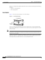
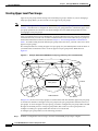
Typical Topologies 1-7
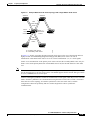
Core Switch 1-8
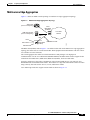
Multiservice Edge Aggregation
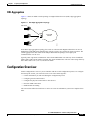
DSL Aggregation 1-11
Configuration Overview
xlv
1-9
1-11
1-12
Cisco MGX 8800/8900 Series Software Configuration Guide
Release 5.1, Part Number OL-6482-01, Rev. A0, January 25, 2005
iii
Contents
Unique Switch Name 1-12
IP Addressing Plan 1-12
ATM Addressing Plan 1-12
Administrator Data 1-13
Unique Device Identifier 1-13
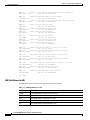
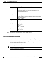
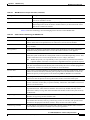
MIB Field Names for UDI 1-14
Administrator Access Method 1-15
Network Clock Source Plan 1-15
Network Management Plan 1-15
Physical Location of Cards and Lines in the Switch
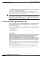
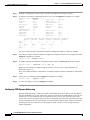
Guidelines for Creating an IP Address Plan
1-15
1-16
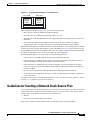
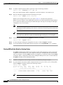
Guidelines for Creating a Network Clock Source Plan 1-17
Planning for Manual Clock Synchronization 1-18
Planning for NCDP Synchronization 1-21
CHAPTER
2
Configuring General Switch Features
Configuration Quickstart
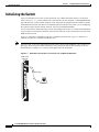
Initializing the Switch
2-1
2-1
2-4
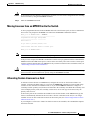
Starting a CLI Management Session After Initialization
Ending a CLI Management Session
2-8
2-10
Entering Commands at the Switch Prompt
2-10
Getting Command Help 2-12
Displaying Command Lists 2-12
Displaying Detailed Command Lists 2-13
Displaying Command Syntax and Parameters
2-15
Configuring User Access 2-15
Adding Users 2-16
Changing Your Own User Password 2-18
Changing User Access Levels and Passwords with cnfuser 2-18
Deleting Users 2-19
Resetting the User cisco Password 2-20
Enabling and Disabling the User cisco Password Reset 2-20
Setting and Viewing the Node Name
2-21
Viewing and Setting the Switch Date and Time
Configuring PNNI Node Parameters 2-22
Adding the PNNI Controller 2-23
Setting the PNNI Level and Peer Group ID
Setting the PNNI Node Address 2-25
2-21
2-24
Cisco MGX 8800/8900 Series Software Configuration Guide
iv
Release 5.1, Part Number OL-6482-01, Rev. A0, January 25, 2005
Contents
Setting the PNNI Node ID 2-27
Setting and Viewing the SPVC Prefix 2-28
Displaying PNNI Summary Addresses 2-29
Configuring the MPLS Controller
2-30
Configuring Clock Sources 2-30
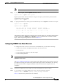
Manually Configuring BITS Clock Sources
Enabling NCDP on a Node 2-34
2-32
Setting the LAN IP Addresses 2-36
Setting the Boot IP Address 2-36
Setting the Disk IP Address 2-39
Starting a CLI Session Through the LAN Port
2-41
Configuring for Network Management 2-42
Configuring the SNMP Trap Source IP Address 2-43
Configuring the SNMP Manager Destination IP Address 2-43
Configuring the Community String and General Switch Information
Verifying the Hardware Configuration
CHAPTER
3
2-44
2-45
Provisioning PXM1E Communication Links
3-1
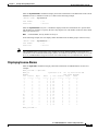
Quickstart Provisioning Procedures 3-2
Line Configuration Quickstart 3-2
ATM Trunk Configuration Quickstart 3-3
PNNI UNI Port Configuration Quickstart 3-5
SVC Configuration Quickstart 3-7
SPVC and SPVP Configuration Quickstart 3-8
PNNI Virtual Trunk Configuration Quickstart 3-9
BPX PNNI Trunk Configuration Quickstart 3-12
AINI Link Configuration Quickstart 3-14
IISP Link Configuration Quickstart 3-15
XLMI Link Configuration Quickstart 3-17
Cisco IGX Feeder to MGX 8830 or MGX 8850 (PXM1E) Configuration Quickstart
3-19
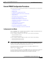
General PXM1E Configuration Procedures 3-21
Configuring the Card Mode 3-21
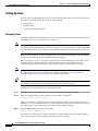
Setting Up Lines 3-22
Bringing Up Lines 3-22
Configuring Lines 3-23
Verifying Line Configuration 3-27
Configuring Inverse Multiplexing for ATM 3-28
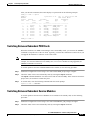
Creating an IMA Group 3-29
Configuring an IMA Group 3-31
Cisco MGX 8800/8900 Series Software Configuration Guide
Release 5.1, Part Number OL-6482-01, Rev. A0, January 25, 2005
v
Contents
Adding an IMA Link to an IMA Group 3-34
Configuring IMA Links 3-35
Adding an IMA Port 3-36
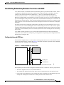
Establishing Redundancy Between Two Lines with APS 3-39
Configuring Intracard APS Lines 3-39
Configuring Intercard APS Lines 3-41
Adding ATM Ports 3-43
Modifying ATM Ports 3-46
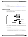
Partitioning Port Resources Between Controllers 3-47
Selecting the Port Signaling Protocol 3-51
Defining Destination Addresses for Static Links 3-55
Assigning Static ATM Addresses to Destination Ports 3-57
Configuring ILMI on a Port 3-59
Configuring ILMI Traps and Signaling 3-59
Configuring ILMI Automatic Configuration 3-61
Configuring ILMI Dynamic Addressing 3-62
Starting ILMI with the Default or Existing Values 3-64
Configuring PXM1E Line Clock Sources 3-65
Verifying PNNI Communications 3-66
Verifying PNNI Trunk Communications 3-67
Verifying End-to-End PNNI Communications 3-68
Provisioning and Managing SPVCs and SPVPs 3-69
Configuring Point-to-Point Connections 3-69
Configuring Point-to-Multipoint Connections 3-80
Adding Parties to a P2MP Root Connection 3-81
Obtaining the NSAP for a Party 3-83
Displaying a List of Connections 3-84
Displaying the Status of a Single Connection 3-85
Modifying P2P and P2MP Connections 3-86
Bringing Down a Connection 3-86
Bringing Up a Connection 3-87
Bringing Down a Party 3-87
Bringing Up a Party 3-87
Rerouting Connections 3-87
Rerouting a P2MP Party 3-87
Deleting Connections 3-88
Deleting a P2MP Party 3-89
Configuring and Managing a Connection to an IGX Feeder 3-89
Connecting a PXM1E Card to a UXM Card on an IGX feeder 3-89
Deleting an IGX Feeder 3-90
Cisco MGX 8800/8900 Series Software Configuration Guide
vi
Release 5.1, Part Number OL-6482-01, Rev. A0, January 25, 2005
Contents
CHAPTER
4
Preparing Service Modules for Communication
Configuration Quickstart
4-1
4-2
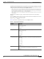
Managing Firmware Version Levels for Service Modules
Locating Cards that Need the Firmware Version Set
Initializing Service Modules 4-4
Verifying Card Firmware Version Levels 4-5
4-3
4-3
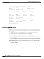
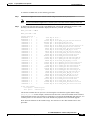
Selecting MPSM Interfaces and Services 4-7
Configuring MPSM-8-T1E1 Interfaces and Services 4-7
Configuring MPSM-T3E3-155 and MPSM-16-T1E1 Interfaces and Services
Establishing Redundancy Between Two Service Modules
CHAPTER
5
Selecting a Card SCT
4-10
Selecting a Port SCT
4-12
Preparing SRM Cards for Communications
4-8
4-8
5-1
Configuration Quickstart for Bulk Distribution on SRMs Configured for SONET/SDH
5-2
Configuration Quickstart for Bulk Distribution on SRMs Configured for T3 Interfaces
5-3
Setting Up SRM Lines 5-4
Bringing Up Lines 5-4
Configuring Lines on an SRM Card 5-5
Configuring a SONET/SDH Line 5-5
Configuring T3 Lines 5-7
Establishing Redundancy Between SONET/SDH Lines with APS
Linking Service Module Lines to SRM Channels, VTs, or VCs
Where To Go Next
CHAPTER
6
Configuration Quickstart
6-1
6-1
Locating RPM Cards in the Switch
6-2
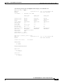
Understanding dspcds and dspcd Displays for RPM
Initializing RPM Cards
6-8
Establishing Redundancy Between RPM Cards
Configuring SNMP on the RPM Card
7
6-9
6-10
6-11
Managing Service Class Templates
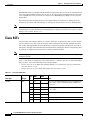
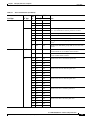
Cisco SCTs
6-2
6-4
Verifying the Software Version in Use
CHAPTER
5-12
5-18
Preparing RPM Cards for Operation
Where to Go Next
5-9
7-1
7-2
Cisco MGX 8800/8900 Series Software Configuration Guide
Release 5.1, Part Number OL-6482-01, Rev. A0, January 25, 2005
vii
Contents
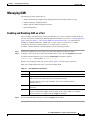
Managing SCTs 7-4
Locating SCT Files on a Switch 7-5
SCT File Naming Convention 7-5
Creating and Modifying SCT Files 7-6
Downloading SCT Files to the Switch 7-7
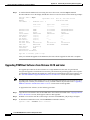
Registering SCT Files 7-7
Updating Registered SCT Files 7-9
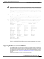
Applying a New Major Version of an AXSM SCT to a Card or Port
Deleting a Registered SCT 7-11
Deleting Unregistered SCTs 7-12
Displaying all Registered Card and Port SCTs on a Switch 7-12
Managing Card SCTs
7-10
7-13
Managing PXM1E Port SCTs 7-13
Displaying the SCT Assigned to a Port 7-13
Selecting a Port SCT 7-14
Changing a Port SCT 7-14
Displaying Port SCT Settings 7-14
Port SCT ABR Parameters (dspportsct abr) 7-15
Port SCT Bandwidth Parameters (dspportsct bw) 7-16
Port SCT General Parameters (dspportsct gen) 7-18
Port SCT COSB Parameters (dspportsct cosb) 7-20
Port SCT Virtual Circuit Threshold Parameters (dspportsct vcThr)
Port SCT COSB Threshold Parameters (dspportsct cosThr) 7-24
CHAPTER
8
Managing PNNI Nodes and PNNI Routing
7-21
8-1
Managing PNNI Nodes 8-1
Creating Upper Level Peer Groups 8-2
Enabling and Disabling the Complex Node Feature 8-5
Enabling and Disabling Routes Through a Node 8-5
Enabling and Disabling Point-to-Multipoint Branching 8-6
Adding an ATM Summary Address Prefix 8-6
Configuring SVCC RCC Variables 8-7
Configuring Routing Policies for Shortest Path Tables 8-7
Configuring PNNI Timers 8-9
Managing PNNI Routes 8-10
Configuring the On-Demand Route Selection Method (First Fit or Best Fit)
Configuring the Load Balance Selection Method 8-11
Managing Preferred Routes 8-11
Maintaining the Network Node Table 8-12
8-10
Cisco MGX 8800/8900 Series Software Configuration Guide
viii
Release 5.1, Part Number OL-6482-01, Rev. A0, January 25, 2005
Contents
Creating a Preferred Route 8-13
Modifying a Preferred Route 8-17
Deleting a Preferred Route 8-18
Deleting a Node from the Network Node Table 8-19
Configuring Link Selection for Parallel Links 8-19
Configuring the Maximum Bandwidth for a Link 8-19
Configuring the Administrative Weight 8-20
Configuring the Aggregation Token 8-20
Configuring the Bandwidth Overbooking Factor 8-21
Configuring the Deroute Delay 8-22
Improving and Managing Rerouting Performance 8-23
Pure PXM45/C Networks 8-23
Hybrid Networks with PXM45/C and PXM45/B 8-23
Pure PXM45/B Networks Running Version 3.0.10 or Later
Hybrid Networks with PXM45/C and PXM45/A 8-24
8-23
Managing Priority Routing 8-24
Establishing Priority Routing on a Node 8-25
Configuring Priority Routing for an SPVC 8-26
Modifying SPVC Priority Routing Configuration 8-27
Configuring Priority Routing for an SVCs 8-27
Managing Priority Bumping 8-28
Enabling, Configuring, and Disabling Priority Bumping
Displaying the Priority Bumping Configuration 8-29
Displaying Priority Bumping Statistics 8-29
Resetting the Priority Bumping Statistics 8-30
Displaying Priority Bumping Resource Usage 8-30
8-28
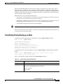
Managing Connection Grooming 8-31
How Grooming Reroutes Connections 8-31
Enabling and Disabling Soft Rerouting for Grooming 8-33
Configuring Scheduled Grooming 8-33
Manually Grooming Connections 8-36
Configuring the Grooming Thresholds 8-36
Configuring Orderly Grooming 8-40
Configuring the Trunk Utilization Limit 8-41
Displaying Grooming Configuration Parameters 8-42
Displaying Threshold and Schedule Configuration Parameters
Displaying Nodal Grooming Configuration Parameters 8-43
Displaying Grooming Configuration Statistics 8-43
Configuring the AIS Delay 8-44
8-42
Cisco MGX 8800/8900 Series Software Configuration Guide
Release 5.1, Part Number OL-6482-01, Rev. A0, January 25, 2005
ix
Contents
Enabling and Disabling the Soft Reroute IE
8-44
Displaying Node Configuration Information 8-45
Displaying the PNNI Node Table 8-45
Displaying the PNNI Summary Address 8-46
Displaying System Addresses 8-47
Displaying PNNI Interface Parameters 8-48
Displaying the PNNI Link Table 8-48
Displaying the PNNI Routing Policy 8-49
Displaying the SVCC RCC Timer 8-50
Displaying Routing Policy Parameters 8-51
Displaying the SVCC RCC Table 8-51
Managing CUGs 8-52
Assigning Address Prefixes and AESAs 8-52
Creating Closed User Groups 8-53
Displaying CUG Configuration Data 8-55
Setting a Default Address for CUG Validation 8-55
Deleting a Default CUG Address 8-56
Managing Access between Users in the Same CUG 8-56
Managing Access between a CUG Member and Non-Members or Members of Other CUGS
Deleting a CUG Assignment 8-59
Blocking the CUG IE 8-60
8-57
Maintaining a Persistent Network Topology for CWM 8-61
Configuring a Gateway Node 8-61
Displaying the Network Topology Database 8-63
Displaying Link Information 8-65
Displaying Feeder Information 8-66
Disabling a Gateway Node 8-68
Deleting a Node from the Topology Database 8-68
Deleting a Link from the Topology Database 8-69
CHAPTER
9
Switch Operating Procedures
9-1
Managing the Configuration Files 9-1
Saving a Configuration 9-1
Clearing a Switch Configuration 9-4
Clearing a Slot Configuration 9-4
Restoring a Saved Switch Configuration
9-5
Managing ILMI 9-7
Enabling and Disabling ILMI on a Port 9-7
Displaying the ILMI Port Configuration 9-8
Cisco MGX 8800/8900 Series Software Configuration Guide
x
Release 5.1, Part Number OL-6482-01, Rev. A0, January 25, 2005
Contents
Displaying and Clearing ILMI Management Statistics
Deleting ILMI Prefixes 9-11
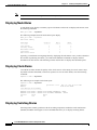
Determining the Software Version Number from Filenames
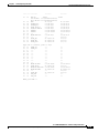
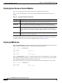
Displaying Software Revisions for Cards 9-14
Displaying Software Revisions in Use 9-14
Displaying Software Revisions for a Single Card
9-10
9-11
9-16
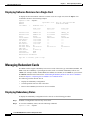
Managing Redundant Cards 9-16
Displaying Redundancy Status 9-16
Switching Between Redundant PXM Cards 9-17
Switching Between Redundant Service Modules 9-17
Removing Redundancy Between Two Cards 9-18
Switching Between Redundant RPM Cards 9-18
Managing Redundant APS Lines 9-18
Preparing for Intercard APS 9-19
Configuring Intercard APS Lines 9-20
Displaying APS Line Information 9-23
Modifying APS Lines 9-24
Switching APS Lines 9-25
Removing APS Redundancy Between Two Lines
Troubleshooting APS Lines 9-26
9-26
Managing the Time of Day Across the Network Using SNTP
Enabling and Configuring SNTP Servers 9-28
Displaying the Current SNTP Configuration 9-30
Displaying an SNTP Server 9-31
Deleting an Existing SNTP Server 9-31
9-28
Managing NCDP Clock Sources 9-31
Enabling NCDP on a Switch 9-32
Configuring an NCDP Clock Source 9-32
Configuring an NCDP Port 9-33
Displaying NCDP Information 9-35
Display the Current NCDP Root Clock 9-35
Display A Specific NCDP Clock Source 9-36
Display All NCDP Clock Sources 9-37
Display All NCDP Ports on the Switch 9-38
Display An NCDP Port 9-38
Deleting an NCDP Clock Source 9-39
Managing Manually Configured Clocks Sources
View the Configured Clock Sources 9-40
Reconfigure Manual Clock Sources 9-41
9-40
Cisco MGX 8800/8900 Series Software Configuration Guide
Release 5.1, Part Number OL-6482-01, Rev. A0, January 25, 2005
xi
Contents
Delete Manual Clock Sources 9-42
Restore a Manual Clock Source After Failure
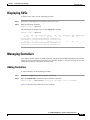
Displaying SVCs
9-42
9-43
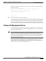
Managing Controllers 9-43
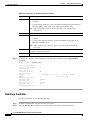
Adding Controllers 9-43
Deleting a Controller 9-44
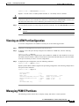
Viewing an ATM Port Configuration
9-45
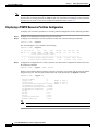
Managing PXM1E Partitions 9-45
Displaying a PXM1E Resource Partition Configuration 9-46
Changing a PXM1E Resource Partition Configuration 9-47
Deleting a PXM1E Resource Partition 9-50
Removing Static ATM Addresses
9-51
Configuring VPI and VCI Ranges for SVCs and SPVCs
9-52
Managing Path and Connection Traces 9-53
Displaying Path and Connection Traces 9-53
Clearing a Call at the Destination Node 9-54
Managing Load Sharing 9-54
Displaying Load Sharing Status
Changing Load Sharing Options
9-54
9-55
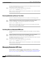
Managing Telnet Access Features 9-56
Starting a Telnet Session from a Workstation 9-56
Starting and Managing Telnet Sessions Between Switches
Starting a Telnet Session 9-56
Returning to a Previous Session 9-57
Returning to the Original CLI Session 9-57
Displaying a Telnet Trace 9-57
Enabling and Disabling Telnet Access 9-58
Displaying the Telnet Enable Status 9-59
9-56
Starting and Managing Secure (SSH) Access Sessions Between Switches
Starting a Secure Session Between Switches 9-60
Returning to the Previous Session 9-62
9-59
Managing Remote (TACACS+) Authentication and Authorization 9-62
Configuring AAA Servers 9-63
Configuring the Cisco MGX Switch to Access AAA Servers 9-63
Configuring the Default Privilege Level 9-66
Configuring the Prompt Override Option 9-66
Configuring User Authentication on the Switch 9-66
Configuring Command Authorization on the Switch 9-68
Cisco MGX 8800/8900 Series Software Configuration Guide
xii
Release 5.1, Part Number OL-6482-01, Rev. A0, January 25, 2005
Contents
Configuring FTP and SSH Messaging Format for AAA Servers 9-69
Displaying the TACACS+ Configuration 9-69
Displaying AAA Server Information 9-70
Displaying AAA Server Statistics 9-70
Avoiding Command Mode Authorization Issues with RPM 9-72
Verifying PXM Disk Data 9-72
Displaying the Contents of the Disk Verification Utility Log File 9-74
Troubleshooting Active and Standby Card Disk Discrepancies 9-77
Configuring a Line Loopback 9-77
Configuring Loopback Line Tests on PXM1E, AXSM, and MPSM Cards
Configuring a Line Loopback on a Service Module 9-78
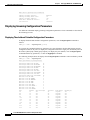
Managing Bit Error Rate Tests 9-79
Configuring a Bit Error Rate Test 9-79
Deleting a Configured Bit Error Rate Test
9-77
9-81
Managing PXM1E and AXSM Card Diagnostics 9-81
Configuring Offline and Online Diagnostics Tests on PXM1E and AXSM Cards 9-82
Enabling Online and Offline Diagnostics Tests on All Cards in a Switch 9-83
Displaying Online and Offline Diagnostics Test Configuration Information 9-84
Displaying Online Diagnostic Errors 9-85
Displaying Offline Diagnostic Errors 9-85
Enabling and Disabling IMA Group ATM Cell Layer Parameters 9-87
Managing IMA 9-88
Displaying IMA Groups 9-89
Displaying the Status of a Single IMA Group 9-89
Displaying IMA Links 9-90
Deleting an IMA Group 9-90
Deleting an IMA Link 9-90
Restarting an IMA Group 9-91
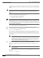
Using Manual IMA Group Restart 9-92
Using Automatic IMA Group Restart 9-92
Displaying the IMA Group Autorestart Configuration and State
CHAPTER
10
9-93
Switch Maintenance Procedures 10-1
Manually Resetting the PXM 10-1
Adding Cards 10-2
Adding a Standby PXM Card 10-2
Adding Service Modules 10-2
Adding SRM Cards 10-4
Adding RPM Cards 10-5
Cisco MGX 8800/8900 Series Software Configuration Guide
Release 5.1, Part Number OL-6482-01, Rev. A0, January 25, 2005
xiii
Contents
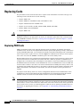
Replacing Cards 10-6
Replacing PXM Cards 10-6
Automatic Response for Standalone PXM Installations 10-7
Automatic Response for Redundant PXM Installations 10-8
Manually Responding to Nativity Checks 10-9
Replacing PXM1E-4-155 Cards with PXM1E-8-155 Cards 10-9
Replacing PXM1E SC Cables with LC Cables via SC Conversion Cables 10-14
Replacing PXM45/A or PXM45/B Cards with PXM45/C Cards 10-16
Gracefully upgrade from a Redundant PXM45 Card Set to a Redundant PXM45/C Card
Set 10-17
Non-gracefully Upgrade a Single PXM45 to a PXM45/C 10-17
Replacing AXSM Cards with AXSM/B Cards 10-18
Upgrading a Standalone AXSM 10-18
Upgrading an AXSM in a Redundant Card Set 10-19
Replacing Service Modules 10-19
Replacing Service Modules with the Same Type of Service Module 10-20
Replacing Eight-Port T1 and E1 Service Modules with MPSM-8-T1E1 10-20
Replacing Service Modules with a Different Type of Service Module 10-24
Replacing SRM Cards with SRME/B 10-24
Replacing RPM Cards 10-25
Decommissioning an AXSM Slot
Decommissioning an RPM Slot
CHAPTER
11
10-25
10-27
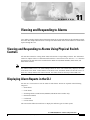
Viewing and Responding to Alarms
11-1
Viewing and Responding to Alarms Using Physical Switch Controls
Displaying Alarm Reports in the CLI 11-1
Displaying Node Alarms 11-2
Displaying Clock Alarms 11-2
Displaying Switching Alarms 11-2
Displaying Environment Alarms 11-5
Displaying Card Alarms 11-6
Displaying Line Alarms on Service Modules
Displaying IMA Alarms 11-8
Displaying License Alarms 11-9
Displaying Log File Information
APPENDIX
A
11-8
11-11
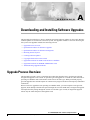
Downloading and Installing Software Upgrades
Upgrade Process Overview
11-1
A-1
A-1
Quickstart Procedures for Software Upgrades
A-2
Cisco MGX 8800/8900 Series Software Configuration Guide
xiv
Release 5.1, Part Number OL-6482-01, Rev. A0, January 25, 2005
Contents
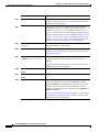
Graceful PXM Boot Upgrades from Releases Prior to Release 3.0.10 A-3
Graceful PXM Boot Upgrades from Release 3.0.10 and Later A-5
Non-Graceful PXM Boot Upgrades A-7
Graceful PXM and Service Module Runtime Software Upgrades A-7
Non-Graceful PXM and Service Module Runtime Software Upgrades A-9
Graceful Service Module Boot Software Upgrades A-11
Non-Graceful Service Module Boot Software Upgrades A-12
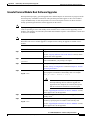
Graceful RPM Boot and Runtime Software Upgrades A-13
Graceful RPM Boot Software Upgrades A-15
Graceful RPM Runtime Software Upgrades A-17
Non-Graceful RPM Boot Software Upgrades A-19
Non-Graceful RPM Runtime Software Upgrades A-20
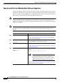
Quickstart Procedures for Software Downgrades A-22
PXM and AXSM Boot Downgrades A-22
Non-Graceful PXM Runtime Software Downgrades A-22
Non-Graceful AXSM Runtime Software Downgrades A-23
Browsing the File System
A-24
Locating Software Updates
A-25
Copying Software Files to the Switch
A-25
Upgrade Procedures for PXM Cards and Service Modules A-26
Upgrading PXM Boot Software from Releases Prior to 3.0.10 A-26
Upgrading PXM Boot Software from Release 3.0.10 and Later A-28
Upgrading Boot Software on Service Modules A-29
Loading the Runtime Upgrade Software A-31
Starting the Upgrade Software A-33
Aborting a Runtime Software Upgrade A-33
Committing to a Runtime Software Upgrade A-34
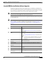
Upgrade Procedures for RPM-PR and RPM-XF Cards A-35
Upgrading RPM Boot Software A-35
Upgrading RPM Runtime Software A-40
Upgrading RPM Runtime Software for 1:N Redundancy A-41
Upgrading RPM Runtime Software for Non-Redundant Cards A-43
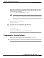
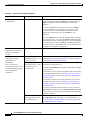
Troubleshooting Upgrade Problems
APPENDIX
B
PXM Backup Boot Procedures
A-45
B-1
Changing to PXM Backup Boot Mode
B-1
Browsing the File System in Backup Boot Mode
Locating Software Updates
B-2
B-4
Cisco MGX 8800/8900 Series Software Configuration Guide
Release 5.1, Part Number OL-6482-01, Rev. A0, January 25, 2005
xv
Contents
Transferring Software Files to and from the Switch
Clearing the Switch Configuration
Initializing the PXM Hard Disk
APPENDIX
B-4
B-5
B-5
Supporting and Using Additional CLI Access Options
C
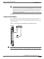
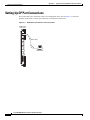
Setting Up CP Port Connections
C-1
C-2
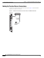
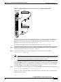
Setting Up Terminal Server Connections
Setting Up Local LAN Connections
C-4
C-6
Setting Up Dial-Up Connections C-6
Configuring the Switch C-8
Configuring the Router C-10
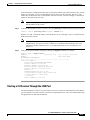
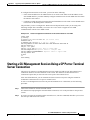
Starting a CLI Management Session Using a CP Port or Terminal Server Connection
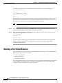
Starting a CLI Telnet Session
C-12
Starting a Secure (SSH) CLI Session
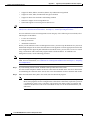
Ending a CLI Management Session
APPENDIX
D
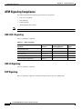
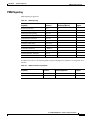
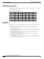
Standards Compliance
PNNI Compliance
C-11
C-13
C-15
D-1
D-1
ATM Signaling Compliance D-2
UNI 3.0/3.1 Signaling D-2
UNI 4.0 Signaling D-2
IISP Signaling D-2
PNNI Signaling D-3
ATM Signaling Interworking D-4
SONET/SDH D-4
APPENDIX
E
Hardware Survey and Software Configuration Worksheets
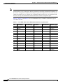
Hardware Survey Worksheets
E-1
E-1
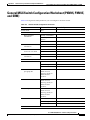
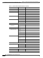
General MGX Switch Configuration Worksheet (PXM45, PXM1E, and SRM)
Additional PXM1E Information Configuration Worksheet
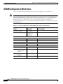
AUSM/B Configuration Worksheet
E-5
E-7
E-11
AXSM Configuration Worksheet
E-12
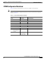
CESM Configuration Worksheet
E-13
FRSM-12-T3E3 Configuration Worksheet
E-14
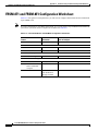
FRSM-2CT3, FRSM-2T3E3, and FRSM-HS2/B Configuration Worksheet
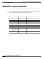
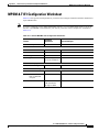
FRSM-8T1 and FRSM-8E1 Configuration Worksheet
MPSM-8-T1E1 Configuration Worksheet
E-15
E-16
E-17
Cisco MGX 8800/8900 Series Software Configuration Guide
xvi
Release 5.1, Part Number OL-6482-01, Rev. A0, January 25, 2005
Contents
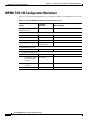
MPSM-T3E3-155 Configuration Worksheet
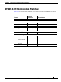
MPSM-16-T1E1 Configuration Worksheet
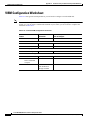
VISM Configuration Worksheet
F
MPSM Licensing
E-19
E-20
VXSM Configuration Worksheet
APPENDIX
E-18
E-21
F-1
MPSM Licensing Information F-1
MPSM License Overview F-1
MPSM License Concepts and Terms F-4
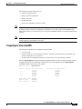
PXM License Pool F-6
Displaying License Data F-7
Displaying All Node Licenses F-7
Displaying Licenses for a Specific MPSM Card Type F-7
Displaying the License Usage for All Cards F-8
Displaying the License Usage for a Specific Card F-9
Displaying a History of License Updates F-10
Displaying License Alarms F-10
Adding Licenses Purchased from Cisco.com F-11
Moving Licenses from an MPSM Card to the Switch F-13
Allocating Feature Licenses to a Card F-13
Recovering Feature Licenses That are Not In Use F-14
Saving and Restoring the License Configuration F-14
Transferring Licenses between Switches F-14
MPSM License Alarms F-18
Node License Alarm F-18
Slot License Alarms F-19
Rekeying Feature Licenses F-21
APPENDIX
G
Reliability, Availability, and Serviceability
Diagnostics G-1
Diagnostics Examples G-2
Diagnostics Tests G-4
PXM1E Diagnostics Tests
PXM45 Diagnostics Tests
G-1
G-5
G-5
INDEX
Cisco MGX 8800/8900 Series Software Configuration Guide
Release 5.1, Part Number OL-6482-01, Rev. A0, January 25, 2005
xvii
Contents
Cisco MGX 8800/8900 Series Software Configuration Guide
xviii
Release 5.1, Part Number OL-6482-01, Rev. A0, January 25, 2005
F I G U R E S
Figure 1-1
Core Switch Topology
Figure 1-2
Multiservice Edge Aggregation Topology
Figure 1-3
Virtual Trunk Topology
Figure 1-4
DSL Edge Aggregation Topology
Figure 1-5
Using Multiple IP Addresses for Switch Access
Figure 1-6
Example Network Clock Source Topology with a Single Master Clock Source
Figure 1-7
Example Network Clock Source Topology with Two Master Clock Sources
Figure 1-8
Example NCDP Source Topology
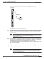
Figure 2-1
Workstation Connection to Console Port on a PXM-UI-S3 Back Card
Figure 2-2
Workstation Connection to Console Port on a PXM-UI-S3/B Back Card
Figure 2-3
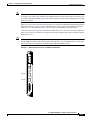
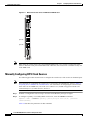
BITS Clock Source Ports on PXM-UI-S3 Back Card
Figure 2-4
BITS Clock Source Ports on PXM-UI-S3/B Back Card
Figure 2-5
Hardware Required for Local LAN Connections to PXM-UI-S3 Back Cards
Figure 2-6
Hardware Required for Local LAN Connections to PXM-UI-S3/B Back Cards
Figure 3-1
Virtual Trunk Topology
Figure 3-2
Standalone PXM1E with Intracard APS
Figure 3-3
Redundant PXM1E Configuration with Intercard APS
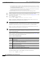
Figure 3-4
Relationship Between Cards, Bays, Lines, and Logical Interface Numbers
Figure 3-5
Relationship of Port Controller, Controller Partition, and Resource Partitions
Figure 3-6
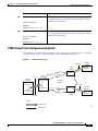
IGX Feeder Topology
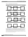
Figure 8-1
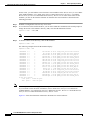
Example Hierarchical PNNI Network Topology Showing a Two-Level Hierarchy
Figure 8-2
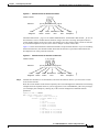
Soft Reroute Method of Connection Grooming
Figure 9-1
Filename Format for Released Software
Figure 9-2
Filename Format for Prereleased Firmware
Figure 9-3
IMA Group Restart Example
Figure 10-1
PXM1E-4-155 Back Cards with SC Cable
Figure 10-2
Standby SFP-8-155 Back Card with SC Conversion Cable
Figure 10-3
Both SFP-8-155 Back Cards with SC Conversion Cables
Figure C-1
Workstation Connection to the Console Port
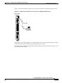
Figure C-2
Workstation Connection to Console Port on a PXM-UI-S3/B Back Card
Figure C-3
Terminal Server Connection to the Console Port on a PXM-UI-S3 Back Card
1-8
1-9
1-10
1-11
1-17
1-19
1-20
1-22
2-4
2-5
2-31
2-32
2-39
2-40
3-9
3-39
3-41
3-45
3-48
3-89
8-2
8-32
9-13
9-13
9-91
10-15
10-15
10-16
C-2
C-3
C-4
Cisco MGX 8800/8900 Series Software Configuration Guide
Release 5.1, Part Number OL-6482-01, Rev. A0, January 25, 2005
xix
Figures
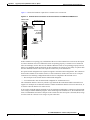
Figure C-4
Terminal Server Connection to the Console Port on a PXM-UI-S3/B Back Card
Figure C-5
Hardware Required for Dial-up Connection to a PXM45 UI-S3 Back Cards
C-6
Figure C-6
Hardware Required for Dial-up Connections on a PXM-UI-S3/B Back Card
C-7
Figure F-1
The Switch License Pool
C-5
F-6
Cisco MGX 8800/8900 Series Software Configuration Guide
xx
Release 5.1, Part Number OL-6482-01, Rev. A0, January 25, 2005
T A B L E S
Table 1
Conventions Used in this Manual
Table 2
Technical Manuals and Release Notes for Cisco MGX and BPX Switches and Media Gateways (January 2005
Product Releases) xxxii
Table 3
Documents that Ship with Multiservice Switch Products
Table 4
Descriptions of Technical Manuals and Release Notes for Cisco Multiservice Switch Products
Table 1-1
Card-specific Configuration Guides
Table 1-2
Changes to This Guide Since Release 5
Table 1-3
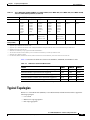
Cisco MGX 8850 (PXM1E/PXM45), Cisco MGX 8850/B, Cisco MGX 8950, Cisco MGX 8830, Cisco MGX 8830/B,
and Cisco MGX 8880 Capabilities 1-4
Table 1-4
Differences between PXM 45 Cards
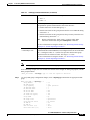
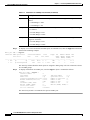
Table 1-5
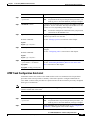
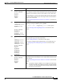
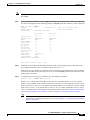
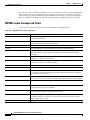
Show Inventory Command Display Output
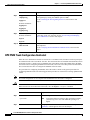
Table 1-6
MIB Field Names for UDI
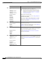
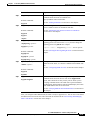
Table 2-1
CLI Prompt Components
2-7
Table 2-2
Card State Descriptions
2-14
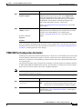
Table 2-3
User Access Levels
Table 2-4
Time Zones for cnftmzn Command
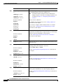
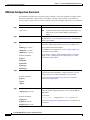
Table 2-5
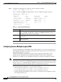
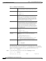
Parameter Descriptions for the addcontroller Command
Table 2-6
Parameter Descriptions for cnfclksrc Command on the PXM
Table 2-7
cnfncdp Command Parameters
Table 2-8
bootChange Command Option Descriptions
Table 3-1
PXM1E Link and Connection Types
Table 3-2
Parameters for cnfln Command
Table 3-3
dspln Command Parameters
Table 3-4
addimagrp Command Parameters
3-30
Table 3-5
cnfimagrp Command Parameters
3-32
Table 3-6
cnfimalnk Command Parameters
3-35
Table 3-7
Parameters for addimaport Command
Table 3-8
APS Line Architecture Modes
Table 3-9
Parameters for addport and cnfport Commands
Table 3-10
Parameters for the addpart Command
Table 3-11
Port Identification Parameters
Table 3-12
Port Signaling Configuration Parameters
xxix
xxxviii
xxxix
1-2
1-3
1-7
1-13
1-14
2-16
2-22
2-23
2-33
2-34
2-38
3-1
3-23
3-28
3-37
3-40
3-44
3-49
3-52
3-53
Cisco MGX 8800/8900 Series Software Configuration Guide
Release 5.1, Part Number OL-6482-01, Rev. A0, January 25, 2005
xxi
Tables
Table 3-13
ATM Address Configuration Parameters
3-56
Table 3-14
ATM Address Configuration Parameters
3-58
Table 3-15
cnfilmi Command Configuration Parameters
Table 3-16
Parameter Descriptions for cnfclksrc Command when Used for PXM1E
Table 3-17
Parameters for the addcon and cnfcon Commands
Table 3-18
addparty Command Parameters
Table 3-19
Optional Parameters for the dspcons Command
Table 4-1
cnfcdmode Command Parameters
Table 4-2
MPSM-8-T1E1 Card Names in the dspcd and dspcds Command Displays
Table 5-1
Parameters for SONET Line Configuration
Table 5-2
Parameters for T3 Line Configuration
Table 5-3
Working and Protection Indexes for addapsln Command
Table 5-4
APS Line Architecture Modes
Table 5-5
cnfapsln Command Parameters
Table 5-6
addlink Command Parameters
Table 5-7
SRM SONET Virtual Tributary Mapping
Table 5-8
SRM SDH AU3 TUG-2 and TU/VC Mapping
Table 5-9
SRM SDH AU4 TUG-3, TUG-2, and TU/VC Mapping
Table 7-1
Cisco Provided SCTs
Table 7-2
SCT Naming Conventions
Table 7-3
addsct and cnfsct Command Parameters
Table 7-4
delsct Command Parameters
Table 7-5
dspscts Command Display Components
Table 7-6
Options for dspportsct Command
Table 7-7
SCT ABR Descriptions
Table 7-8
SCT Bandwidth Parameter Descriptions
Table 7-9
SCT General Parameter Descriptions
Table 7-10
SCT COSB Parameter Descriptions
Table 7-11
SCT VC Threshold Parameter Descriptions
Table 7-12
Class of Service (CoS) Scaling Table
Table 7-13
Logical Interface Scaling Table
Table 7-14
SCT COSB Threshold Parameter Descriptions
Table 8-1
Parameters for addpnni-summary-addr Command
Table 8-2
Parameters for cnfpnni-svcc-rcc-timer Command
8-7
Table 8-3
Parameters for cnfpnni-routing-policy Command
8-8
3-60
3-66
3-70
3-82
3-84
4-7
4-8
5-6
5-8
5-10
5-10
5-11
5-13
5-14
5-15
5-17
7-2
7-6
7-8
7-11
7-12
7-15
7-16
7-17
7-19
7-21
7-22
7-23
7-23
7-25
8-7
Cisco MGX 8800/8900 Series Software Configuration Guide
xxii
Release 5.1, Part Number OL-6482-01, Rev. A0, January 25, 2005
Tables
Table 8-4
Parameters for cnfpnni-timer Command
Table 8-5
addnwnode Command Parameters
Table 8-6
addpref Command Parameters
Table 8-7
addcon and cnfcon Preferred Route Command Parameters
Table 8-8
Parameters for cnfpref Command
Table 8-9
cnfpri-routing Command Parameters
Table 8-10
Parameters for cnfrteopt Command
Table 8-11
Parameters for optrte Command
8-36
Table 8-12
Supported Grooming Thresholds
8-37
Table 8-13
Grooming Metric Selection
Table 8-14
Parameters for cnfrteoptthresh Command
Table 8-15
Parameters for cnfndrteopt Command
Table 8-16
Objects Displayed for dsppnni-summary-addr Command
Table 8-17
Objects Displayed for the dsppnni-intf Command
Table 8-18
Objects Displayed for the dsppnni-routing-policy Command
8-50
Table 8-19
Objects Displayed for the dsppnni-svcc-rcc-timer Command
8-51
Table 8-20
addcug/dspcug Command Parameters and Options
Table 8-21
setcugdefaddr Command Parameters
Table 8-22
cnfaddrcug Command Parameters
Table 8-23
Valid Operational and Admin State Combinations
Table 8-24
Topology Database Feeder Node Information
Table 9-1
Port Identification Parameters
Table 9-2
Column Descriptions for dspilmis and dspilmi Commands
9-8
Table 9-3
Determining Firmware Version Numbers from Filenames
9-14
Table 9-4
cnfapsln Command Parameters
Table 9-5
switchapsln Command Parameters
Table 9-6
Options for cnfapsln Command
Table 9-7
Options for switchapsln Command
Table 9-8
Troubleshooting APS Line Problems Using the dspaps Command
Table 9-9
Troubleshooting Card Problems
Table 9-10
cnfsntp Command Parameters
Table 9-11
cnfsntprmtsvr Command Parameters
Table 9-12
Objects Displayed for dspsntp Command
Table 9-13
cnfncdp Command Parameters
Table 9-14
cnfncdpclksrc Command Parameters
8-10
8-13
8-14
8-16
8-17
8-25
8-34
8-38
8-39
8-40
8-46
8-48
8-54
8-56
8-58
8-62
8-64
9-7
9-21
9-23
9-24
9-25
9-27
9-28
9-29
9-30
9-30
9-32
9-33
Cisco MGX 8800/8900 Series Software Configuration Guide
Release 5.1, Part Number OL-6482-01, Rev. A0, January 25, 2005
xxiii
Tables
Table 9-15
cnfncdpport Command Parameters
Table 9-16
dspncdp Command Objects
Table 9-17
dspncdpclksrc Command Objects
Table 9-18
dspncdpclksrcs Command Objects
Table 9-19
dspncdpports Command Objects
Table 9-20
dspncdpport Command Objects
Table 9-21
delncdpclksrc Command Objects
Table 9-22
Parameters for the addcontroller Command
Table 9-23
Parameters for the cnfpart Command
Table 9-24
ATM Address Configuration Parameters
Table 9-25
Parameters for the cnfpnportrange Command
Table 9-26
Path and Connection Trace Commands
9-54
Table 9-27
Command Parameters for cnfxbarmgmt
9-55
Table 9-28
Command Parameters for ssh
Table 9-29
Parameters for cnfaaa-server Command
Table 9-30
Keywords for cnfaaa_authen and cnfaaa-author Commands
Table 9-31
verifydiskdb check Command Parameters
Table 9-32
verifydiskdb status Command Display
Table 9-33
dspbertcap Command Parameters
Table 9-34
cnfbert Command Parameters
9-80
Table 9-35
cnfdiag Command Parameters
9-82
Table 9-36
cnfdiagall Command Parameters
Table 9-37
cnfatmimagrp Command Parameters
Table 10-1
Automatic Response to Nativity Checks in Standalone Installations
Table 10-2
Mastership Assignment to PXM Card Sets after Nativity Check
Table 11-1
Crossbar Alarm Troubleshooting Commands
Table 11-2
Card Alarm Information Commands
11-7
Table 11-3
Line Alarm Information Commands
11-8
Table A-1
File System Commands at Switch Prompt
Table A-2
Software Versions Reported During Graceful Upgrades
Table A-3
Software Versions Reported During Non-Graceful Upgrades
Table A-4
Troubleshooting Upgrade Problems
Table B-1
File System Commands at Backup Boot Prompt
Table D-1
UNI 3.x Signaling
Table D-2
PNNI Signaling
9-34
9-35
9-37
9-37
9-38
9-39
9-40
9-44
9-47
9-51
9-52
9-60
9-64
9-67
9-73
9-74
9-79
9-83
9-88
10-7
10-8
11-4
A-24
A-32
A-32
A-46
B-3
D-2
D-3
Cisco MGX 8800/8900 Series Software Configuration Guide
xxiv
Release 5.1, Part Number OL-6482-01, Rev. A0, January 25, 2005
Tables
Table D-3
PNNI 2.0 Interface Capabilities
Table D-4
ATM Signaling Interworking
Table E-1
Cisco MGX 8830 or Cisco MGX 8830/B Hardware Survey Worksheet
Table E-2
Cisco MGX 8850 (PXM1E/PXM45) or Cisco 8850/B Hardware Survey Worksheet
Table E-3
Cisco MGX 8950 Hardware Survey Worksheet
Table E-4
General Switch Configuration Parameters
Table E-5
Additional PXM1E Card Configuration Parameters
Table E-6
General AUSM/B Configuration Parameters
Table E-7
General AXSM, AXSM-E, and AXSM-XG Card Configuration Parameters
Table E-8
General CESM Configuration Parameters
Table E-9
General FRSM12 Card Configuration Parameters
Table E-10
General FRSM-2CT3, FRSM-2T3E3, and FRSM-HS2/B Configuration Parameters
Table E-11
General FRSM-8T1 and FRSM-8E1 Configuration Parameters
Table E-12
General MPSM-8-T1E1 Configuration Parameters
Table E-13
General MPSM-T3E3-155 Card Configuration Parameters
E-18
Table E-14
General MPSM-T3E3-155 Card Configuration Parameters
E-19
Table E-15
General VISM Configuration Parameters
Table E-16
General VXSM Card Configuration Parameters
Table F-1
Available Licensed Services for MPSM Cards
Table F-2
Feature Options for MPSM Services
F-3
Table F-3
MPSM License Concepts and Terms
F-4
Table F-4
Feature LIcense Terminology for MPSM Cards
Table G-1
RAS-Related Diagnostics, Alarm, and POST Commands
D-3
D-4
E-2
E-3
E-4
E-5
E-7
E-11
E-12
E-13
E-14
E-15
E-16
E-17
E-20
E-21
F-2
F-5
G-2
Cisco MGX 8800/8900 Series Software Configuration Guide
Release 5.1, Part Number OL-6482-01, Rev. A0, January 25, 2005
xxv
Tables
Cisco MGX 8800/8900 Series Software Configuration Guide
xxvi
Release 5.1, Part Number OL-6482-01, Rev. A0, January 25, 2005
About This Guide
This preface describes the objectives, audience, organization, and conventions of the Cisco MGX
8800/8900 Series Software Configuration Guide.
Objectives
This guide describes how to configure the Cisco MGX 8850, Cisco MGX 8850/B, Cisco MGX 8950,
Cisco MGX 8830, Cisco 8830/B switches and the Cisco MGX 8880 Media Gateway. This guide also
describes how to perform some operating procedures after the switch begins operation.
Audience
The Cisco MGX 8800/8900 Series Software Configuration Guide provides network operators and
administrators with configuration procedures for setting up these same Cisco switches and media
gateway.
Organization
The major sections of this document are as follows:
•
Chapter 1, “Preparing for Configuration,” describes information you will need during configuration
and provides planning guidelines for configuration.
•
Chapter 2, “Configuring General Switch Features,” describes how to configure features that apply
to the entire switch, rather than to a single card, line, or trunk.
•
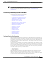
Chapter 3, “Provisioning PXM1E Communication Links,” describes how to prepare PXM1E lines
for physical connectivity to other switches.
•
Chapter 4, “Preparing Service Modules for Communication,” describes how to initialize service
modules in preparation for provisioning.
•
Chapter 5, “Preparing SRM Cards for Communications,” describes how to configure the PXM to
use the bulk distribution feature provided by SRM cards.
•
Chapter 6, “Preparing RPM Cards for Operation,” describes how to initialize RPM-PR and RPM-XF
cards in the switch, determine the software versions in use, and configure 1:N card redundancy.
Cisco MGX 8800/8900 Series Software Configuration Guide
Release 5.1, Part Number OL-6482-01, Rev. A0, January 25, 2005
xxvii
About This Guide
Organization
•
Chapter 7, “Managing Service Class Templates,” describes how to download and use service class
templates for AXSM, PXM1E, and FRSM12 cards.
•
Chapter 8, “Managing PNNI Nodes and PNNI Routing,” provides information you can use to
optimize PNNI routing.
•
Chapter 9, “Switch Operating Procedures,” describes how to manage your configuration after the
switch is configured and during day-to-day operation.
•
Chapter 10, “Switch Maintenance Procedures,” provides procedures for adding and replacing cards
after the initial installation and configuration of the switch.
•
Chapter 11, “Viewing and Responding to Alarms,” describes the controls available on the switch
and how to view switch alarms.
•
Appendix A, “Downloading and Installing Software Upgrades,” explains how to upgrade switch
software.
•
Appendix B, “PXM Backup Boot Procedures,” describes special procedures you can use to manage
the switch when only the boot software is loaded.
•
Appendix C, “Supporting and Using Additional CLI Access Options,”describes alternative ways to
connect management workstations to the switch.
•
Appendix D, “Standards Compliance,” describes the technical and compliance specifications for
Cisco MGX switches and the Cisco MGX 8880 Media Gateway.
•
Appendix E, “Hardware Survey and Software Configuration Worksheets,” provides worksheets that
you can use to plan for or record the configuration of Cisco MGX switches and the Cisco MGX 8880
Media Gateway.
•
Appendix F, “MPSM Licensing,” provides details about licensing management features and
procedures for MPSM service modules.
•
Appendix G, “Reliability, Availability, and Serviceability,” provides details about reliability,
availability, and serviceability diagnostic features supported by the PXM1E and PXM 45 controller
cards.
Conventions
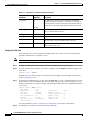
This manual uses the conventions listed in this section and in Table 1.
MGX switches collectively refers to all the multiservice switches and gateways documented in this
manual—the Cisco MGX 8850 (PXM1E) switch, the Cisco MGX 8850 (PXM45) switch, the Cisco
MGX 8850/B, the Cisco MGX 8950 switch, the Cisco MGX 8830 switch, the Cisco MGX 8830/B and
the Cisco MGX 8880 Media Gateway. Often, Cisco MGX 8850 (PXM1E) and Cisco MGX 8850
(PXM45) are referred together at Cisco MGX 8850 (PXM1E/PXM45).
Cisco MGX 8800/8900 Series Software Configuration Guide
xxviii
Release 5.1, Part Number OL-6482-01, Rev. A0, January 25, 2005
About This Guide
Organization
Table 1
Conventions Used in this Manual
Convention
Definition
Sample
boldface font
Commands and keywords are in boldface.
This is similar to the UNIX
route command.
Also used for names of some elements in a
graphical user interface (GUI).
italic font
Terminal sessions and information the
system displays are in screen font.
Are you ready to continue? [Y]
Information you must enter is in boldface
screen font.
Login: root
Password: <password>
^
The symbol ^ represents the Control key
labeled Ctrl.
^D This key combination in a
screen display means hold down the
Control key while you press the
D key.
[ ]
Elements in square brackets are optional.
[no] offset-list {in | out} offset
screen
font
Arguments for which you supply values are See the Regulatory Compliance and
Safety Information for Cisco
in italics.
Multiservice Switch and Media
Also used for publication names and for
Gateway Products (MGX, BPX, and
emphasis.
SES) for further details.
boldface screen
font
Also used for default responses to system
prompts.
{x | y | z}
Alternative keywords are grouped in braces offset-list {in | out} offset
and separated by vertical bars.
< >
Nonprinting characters such as passwords
are in angle brackets.
Password: <cisco123>
{}
Braces indicate a required choice.
offset-list {in | out} offset
[{ }]
Braces within a bracket indicate a required [{letter\number}Enter]
choice within an optional element.
Notes, Warnings, and Cautions
This section explains the conventions used for notes, warnings, and cautions.
Note
Caution
Means reader take note. Notes contain helpful suggestions or references to material not
covered in the manual.
Means reader be careful. In this situation, you might do something that could result in
equipment damage or loss of data.
Cisco MGX 8800/8900 Series Software Configuration Guide
Release 5.1, Part Number OL-6482-01, Rev. A0, January 25, 2005
xxix
About This Guide
Documentation
Tips
Warning
Means the following information will help you solve a problem. The tips information might
not be troubleshooting or even an action, but could be useful information, similar to a
Timesaver.
This warning symbol means danger. You are in a situation that could cause bodily injury. Before you
work on any equipment, you must be aware of the hazards involved with electrical circuitry and be
familiar with standard practices for preventing accidents. (To see translated versions of this warning,
refer to the Regulatory Compliance and Safety Information document that accompanied the product.)
Documentation
A Guide to Cisco Multiservice Switch and Media Gateway Documentation ships with your product. That
guide contains general information about how to locate Cisco MGX, BPX, SES, and CWM
documentation online.
Documentation Notes for these Product Releases
This release includes new hardware or features for the following releases:
•
Cisco MGX Release 5.1 introduces the Cisco MGX 8850/B multiservice switch
•
Cisco MGX Release 5.1, for these multiservice switches:
– Cisco MGX 8850 (PXM1E)
– Cisco MGX 8850 (PXM45)
– Cisco MGX 8950
– Cisco MGX 8830
•
Cisco MGX Release 1.3, for these multiservice switches:
– Cisco MGX 8850 (PXM1)
– Cisco MGX 8230
– Cisco MGX 8250
•
Cisco MGX Release 5.1, for the Route Processor Modules (RPM-XF and RPM-PR)
•
Cisco WAN Manager Release 15.1. CWM Release 15 introduced a helpful new documentation
feature: web-based online help. To invoke online help, press F1 on a PC, press the Help key on a
UNIX workstation, or select Help from the main or popup menu. Cisco WAN Manager online help
has been updated for Release 15.1.
Other components of multiservice WAN products, such as the Service Expansion Shelf (SES) and WAN
switching software have no new features for this release.
Related Documentation
This section describes the technical manuals and release notes that support this release of Cisco
Multiservice Switch products.
Cisco MGX 8800/8900 Series Software Configuration Guide
xxx
Release 5.1, Part Number OL-6482-01, Rev. A0, January 25, 2005
About This Guide
Documentation
Technical Manual Order of Use
Use the technical manuals listed here in the following order:
Step 1
Refer to the documents that ship with your product. Observe all safety precautions.
•
Regulatory Compliance and Safety Information for Cisco Multiservice Switch and Media Gateway
Products (MGX, BPX, and SES)—This document familiarizes you with safety precautions for your
product.
•
Guide to Cisco Multiservice Switch and Media Gateway Documentation—This document explains
how to find documentation for MGX, BPX, and SES multiservice switches and media gateways as
well as CWM network management software. These documents are available only online.
•
Installation Warning Card—This document provides precautions about installing your cards. It
explains such subjects as removing the shipping tab and inserting cards properly into the correct
slots.
Step 2
Refer to the release notes for your product.
Step 3
If your network uses the CWM network management system, upgrade CWM. (If you are going to install
CWM for the first time, do so after Step 4.) Upgrade instructions are included in the following
documents:
Step 4
•
Cisco WAN Manager Installation Guide, Release 15.1
•
Cisco WAN Manager User’s Guide, Release 15.1
If your network contains MGX and SES products, refer to this manual for planning information:
•
Step 5
Step 6
Step 7
Step 8
Note
Cisco PNNI Network Planning Guide for MGX and SES Products
Refer to these manuals for information about installing cards and cables in the MGX chassis:
•
Cisco MGX 8800/8900 Series Hardware Installation Guide, Releases 2 - 5.1 for installing cards and
cables in these chassis.
•
Cisco MGX 8xxx Edge Concentrator Installation and Configuration Guide for installing cards and
cables in the Cisco MGX 8230, Cisco MGX 8250, or Cisco MGX 8850 (PXM1) chassis.
Refer to the manuals that help you configure your MGX switch and processor cards:
•
Cisco MGX 8800/8900 Series Software Configuration Guide, Release 5.1 for these chassis.
•
Cisco MGX 8xxx Edge Concentrator Installation and Configuration Guide for the Cisco MGX
8230, Cisco MGX 8250, or Cisco MGX 8850 (PXM1) chassis.
Refer to the manual that supports the additional cards you intend to install in your switch. For example:
•
The services books can help you establish ATM, Frame Relay, or circuit emulation services on your
switch.
•
The VISM book can help you set up your switch as a voice gateway, and the RPM book can help
you implement IP on the switch.
Additional books, such as command reference guides and error message books, can help with the daily
operation and maintenance of your switch.
Manual titles may be different for earlier software releases. The titles shown in Table 2 are for the
January 2005 release.
Cisco MGX 8800/8900 Series Software Configuration Guide
Release 5.1, Part Number OL-6482-01, Rev. A0, January 25, 2005
xxxi
About This Guide
Documentation
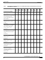
Technical Manual Titles and Descriptions
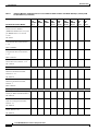
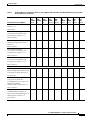
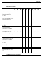
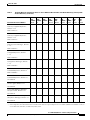
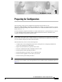
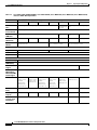
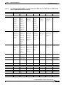
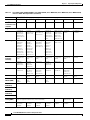
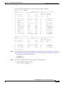
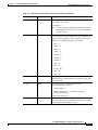
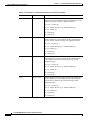
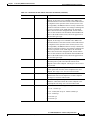
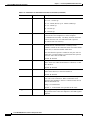
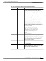
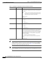
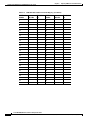
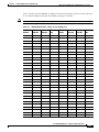
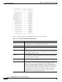
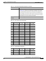
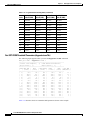
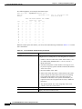
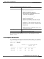
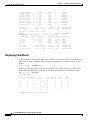
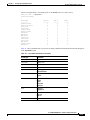
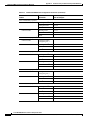
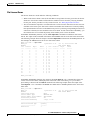
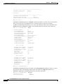
Table 2 lists the technical manuals and release notes that support the January 2005 multiservice switch
product releases. Books and release notes in Table 2 are listed in order of use and include information
about which multiservice switch or media gateway the document supports.
The books for Cisco MGX 8230, Cisco MGX 8250, and Cisco MGX 8850 (PXM1) switches were not
updated for the January 2005 release, therefore, some information about configuring and using the new
MPSM-8-T1E1 card in these switches is included in the following books:
•
Cisco ATM Services (AUSM/MPSM) Configuration Guide and Command Reference for MGX
Switches, Release 5.1
•
Cisco Frame Relay Services (FRSM/MPSM) Configuration Guide and Command Reference for
MGX Switches, Release 5.1
•
Cisco Circuit Emulation Services (CESM/MPSM) Configuration Guide and Command Reference
for MGX Switches, Release 5.1
Information about how to install or upgrade to the MPSM-8-T1E1 card in Cisco MGX 8230, Cisco
MGX 8250, and Cisco MGX 8850 (PXM1) switches is in the Release Notes for Cisco MGX 8230, Cisco
MGX 8250, and Cisco MGX 8850 (PXM1) Switches, Release 1.3.10.
Note
Refer to each product’s release notes for the latest information on features, bug fixes, and more.
Terms
Two main types of ATM cards are used in MGX switches: AXSM and AUSM. AXSM stands for ATM
Switching Service Module. AUSM stands for ATM UNI (User Network Interface) Service Module.
CWM stands for Cisco WAN Manager, our multiservice switch network management system.
Legacy service module refers to a previously introduced card. For this release, the term is used
specifically for the CESM-8-T1E1, FRSM-8-T1E1, and AUSM-8-T1E1 cards, which can now be
replaced by the new MPSM-8-T1E1 card.
MPSM stands for Multiprotocol Service Module.
RPM stands for Route Processor Module.
SES stands for Service Expansion Shelf.
VISM stands for Voice Interworking Service Module.
VXSM stands for Voice Switch Service Module.
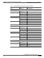
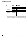
Table 2
Technical Manuals and Release Notes for Cisco MGX and BPX Switches and Media Gateways (January 2005
Product Releases)
Document Title and Part Number
MGX
BPX
MGX
MGX
8850
with SES 8230 Rel. 8250 Rel. (PXM1)
Rel. 4
1.3
1.3
Rel. 1.3
MGX
8830
Rel. 5.1
MGX
8850
(PXM1E)
Rel. 5.1
MGX
8850
(PXM45)
Rel. 5.1
MGX
8950
Rel. 5.1
MGX
8880
Rel. 5.1.
x
x
x
x
x
Overview and Safety Documents
Guide to Cisco Multiservice Switch x
and Media Gateway
Documentation
x
x
x
DOC-7814807=
Cisco MGX 8800/8900 Series Software Configuration Guide
xxxii
Release 5.1, Part Number OL-6482-01, Rev. A0, January 25, 2005
About This Guide
Documentation
Table 2
Technical Manuals and Release Notes for Cisco MGX and BPX Switches and Media Gateways (January 2005
Product Releases) (continued)
Document Title and Part Number
MGX
BPX
MGX
MGX
8850
with SES 8230 Rel. 8250 Rel. (PXM1)
Rel. 4
1.3
1.3
Rel. 1.3
MGX
8830
Rel. 5.1
MGX
8850
(PXM1E)
Rel. 5.1
MGX
8850
(PXM45)
Rel. 5.1
MGX
8950
Rel. 5.1
MGX
8880
Rel. 5.1.
Installation Warning Card
x
x
x
x
x
x
x
x
x
Regulatory Compliance and Safety x
Information for Cisco Multiservice
Switch and Media Gateway
Products (MGX, BPX, and SES)
x
x
x
x
x
x
x
x
—
—
—
—
—
—
—
—
x
Release Notes for Cisco MGX 8850 —
(PXM1E/PXM45), Cisco MGX
8950, and Cisco MGX 8830
Switches, Release 5.1.00
—
—
—
x
x
x
x
x
x
x
—
—
—
—
—
—
—
—
—
—
—
x
—
x
x
x
x
x
x
x
x
x
x
—
x
x
x
x
x
x
—
x
—
—
—
—
x
—
x
x
x
DOC-7812348=
DOC-7814790=
Release Notes for the Cisco MGX
8880 Media Gateway, Release
5.1.00
OL-6493-01
OL-6478-01
Release Notes for Cisco MGX 8230, —
Cisco MGX 8250, and Cisco MGX
8850 (PXM1) Switches, Release
1.3.10
OL-4539-01
Release Notes for the Cisco Voice
Switch Service Module (VXSM),
Release 5.1.00
OL-4627-01
Release Notes for Cisco WAN
Manager, Release 15.1.00
OL-6495-01
Release Notes for the Cisco Voice
Interworking Service Module
(VISM), Release 3.3.00
OL-5357-01
Release Notes for Cisco MGX
Route Processor Module
(RPM-XF) IOS Release 12.3(2)T5
for PXM45-based Switches,
Release 5.0.00
OL-4536-01
Cisco MGX 8800/8900 Series Software Configuration Guide
Release 5.1, Part Number OL-6482-01, Rev. A0, January 25, 2005
xxxiii
About This Guide
Documentation
Table 2
Technical Manuals and Release Notes for Cisco MGX and BPX Switches and Media Gateways (January 2005
Product Releases) (continued)
Document Title and Part Number
Release Notes for Cisco MGX
Route Processor Module
(RPM-PR) IOS Release 12.3(7)T3
for MGX Releases 1.3.10 and
5.0.10
MGX
BPX
MGX
MGX
8850
with SES 8230 Rel. 8250 Rel. (PXM1)
Rel. 4
1.3
1.3
Rel. 1.3
MGX
8830
Rel. 5.1
MGX
8850
(PXM1E)
Rel. 5.1
MGX
8850
(PXM45)
Rel. 5.1
MGX
8950
Rel. 5.1
MGX
8880
Rel. 5.1.
—
x
x
x
x
x
x
x
x
—
x
—
—
—
—
—
—
—
—
—
x
—
—
—
—
—
—
—
—
—
x
—
—
—
—
—
—
—
—
—
x
x
x
x
x
x
—
—
—
—
—
—
—
—
x
—
—
—
x
x
x
x
x
—
—
—
—
x
x
x
x
x
x
x
x
x
x
x
x
x
x
OL-4535-1
Cisco MGX 8230 Edge
Concentrator Overview, Release
1.1.31
DOC-7812899=
Cisco MGX 8250 Edge
Concentrator Overview, Release
1.1.31
DOC-7811576=
Cisco MGX 8850 Multiservice
Switch Overview, Release 1.1.31
OL-1154-01
Hardware Installation Guides
Cisco MGX 8800/8900 Series
Hardware Installation Guide,
Releases 2 - 5.1
OL-4545-01
Cisco Service Expansion Shelf
Hardware Installation Guide,
Release 11
DOC-786122=
Planning and Configuration Guides
Cisco PNNI Network Planning
Guide for MGX and SES Products
OL-3847-01
Cisco MGX 8800/8900 Series
Software Configuration Guide,
Release 5.1
OL-6482-01
Cisco WAN Manager Installation
Guide, Release 15.1
OL-6259-01
Cisco MGX 8800/8900 Series Software Configuration Guide
xxxiv
Release 5.1, Part Number OL-6482-01, Rev. A0, January 25, 2005
About This Guide
Documentation
Table 2
Technical Manuals and Release Notes for Cisco MGX and BPX Switches and Media Gateways (January 2005
Product Releases) (continued)
Document Title and Part Number
MGX
BPX
MGX
MGX
8850
with SES 8230 Rel. 8250 Rel. (PXM1)
Rel. 4
1.3
1.3
Rel. 1.3
Cisco WAN Manager User’s Guide, x
Release 15.1
MGX
8830
Rel. 5.1
MGX
8850
(PXM1E)
Rel. 5.1
MGX
8850
(PXM45)
Rel. 5.1
MGX
8950
Rel. 5.1
MGX
8880
Rel. 5.1.
x
x
x
x
x
x
x
x
—
—
—
x
—
—
—
—
—
x
—
—
—
—
—
—
—
—
—
x
—
—
—
—
—
—
—
—
—
x
—
—
—
—
—
—
x
x
x
—
—
—
—
—
—
—
—
—
—
x
—
—
2
2
2
x
x
x
—
—
OL-6257-01
Cisco MGX 8850 Edge
Concentrator Installation and
Configuration, Release 1.1.31
DOC-7811223=
Cisco SES PNNI Controller
Software Configuration Guide,
Release 31
DOC-7814258=
Cisco MGX 8230 Edge
Concentrator Installation and
Configuration, Release 1.1.31
DOC-7811215=
Cisco MGX 8250 Edge
Concentrator Installation and
Configuration, Release 1.1.31
DOC-7811217=
Service Module Configuration and Reference Guides
—
Cisco MGX Route Processor
Module (RPM-PR) Installation and
Configuration Guide, Release 2.11
78-12510-02
Cisco Frame Relay Software
Configuration Guide and
Command Reference for the Cisco
MGX 8850 (PXM45)
FRSM-12-T3E3 Card, Release 31
—
DOC-7810327=
Cisco ATM Services
—
(AUSM/MPSM) Configuration
Guide and Command Reference for
MGX Switches, Release 5.12
OL-6479-01
Cisco MGX 8800/8900 Series Software Configuration Guide
Release 5.1, Part Number OL-6482-01, Rev. A0, January 25, 2005
xxxv
About This Guide
Documentation
Table 2
Technical Manuals and Release Notes for Cisco MGX and BPX Switches and Media Gateways (January 2005
Product Releases) (continued)
Document Title and Part Number
MGX
BPX
MGX
MGX
8850
with SES 8230 Rel. 8250 Rel. (PXM1)
Rel. 4
1.3
1.3
Rel. 1.3
MGX
8830
Rel. 5.1
MGX
8850
(PXM1E)
Rel. 5.1
MGX
8850
(PXM45)
Rel. 5.1
MGX
8950
Rel. 5.1
MGX
8880
Rel. 5.1.
2
2
2
x
x
x
—
—
2
2
2
x
x
x
—
—
—
—
—
—
—
x
x
x
—
—
—
—
—
—
x
x
x
—
Cisco ATM and Frame Relay
Services (MPSM-T3E3-155 and
MPSM-16-T1E1) Configuration
Guide and Command Reference for
MGX Switches, Release 5.1
—
—
—
x
—
x
—
—
—
—
—
—
—
—
x
—
x
—
x
x
x
x
x
x
—
x
—
x
—
—
—
—
—
—
—
—
Cisco Frame Relay Services
(FRSM/MPSM) Configuration
Guide and Command Reference for
MGX Switches, Release 5.12
OL-6480-01
Cisco Circuit Emulation Services
—
(CESM/MPSM) Configuration
Guide and Command Reference for
MGX Switches, Release 5.12
OL-6481-01
—
Cisco MGX Route Processor
Module (RPM-XF) Installation and
Configuration Guide, Release 5.11
OL-5087-01
Cisco ATM Services (AXSM)
Configuration Guide and
Command Reference for MGX
Switches, Release 5.1
OL-6484-01
OL-6487-01
Cisco Voice Switch Services
(VXSM) Configuration Guide and
Command Reference for MGX
Switches and Media Gateways,
Release 5.1
OL-4625-01
Cisco Voice Interworking Services
(VISM) Configuration Guide and
Command Reference, Release 3.3
OL-5358-01
Reference Guides
Cisco MGX 8230 Multiservice
Gateway Error Messages, Release
1.1.31
DOC-78112113=
Cisco MGX 8800/8900 Series Software Configuration Guide
xxxvi
Release 5.1, Part Number OL-6482-01, Rev. A0, January 25, 2005
About This Guide
Documentation
Table 2
Technical Manuals and Release Notes for Cisco MGX and BPX Switches and Media Gateways (January 2005
Product Releases) (continued)
Document Title and Part Number
Cisco MGX 8230 Multiservice
Gateway Command Reference,
Release 1.1.31
MGX
BPX
MGX
MGX
8850
with SES 8230 Rel. 8250 Rel. (PXM1)
Rel. 4
1.3
1.3
Rel. 1.3
MGX
8830
Rel. 5.1
MGX
8850
(PXM1E)
Rel. 5.1
MGX
8850
(PXM45)
Rel. 5.1
MGX
8950
Rel. 5.1
MGX
8880
Rel. 5.1.
—
x
—
—
—
—
—
—
—
—
—
x
—
—
—
—
—
—
—
—
x
—
—
—
—
—
—
—
x
x
x
—
—
—
—
—
—
x
x
x
—
—
—
—
—
x
—
—
—
—
—
—
—
—
—
—
—
—
x
x
x
x
x
x
x
x
x
x
x
x
x
x
x
x
x
x
x
x
x
x
x
—
—
—
x
x
x
x
x
DOC-7811211=
Cisco MGX 8250 Multiservice
Gateway Command Reference,
Release 1.1.31
DOC-7811212=
Cisco MGX 8250 Multiservice
Gateway Error Messages, Release
1.1.31
DOC-7811216=
Cisco MGX 8800 Series Switch
Command Reference, Release
1.1.31
DOC-7811210=
Cisco MGX 8800 Series Switch
System Error Messages, Release
1.1.31
DOC-7811240=
Cisco SES PNNI Controller
Command Reference, Release 31
DOC-7814260=
Cisco MGX 8800/8900 Series
Command Reference, Release 5.1
OL-6483-01
Cisco WAN Manager SNMP
Service Agent, Release 15.1
OL-6260-01
Cisco WAN Manager Database
Interface Guide, Release 15.1
OL-6261-01
Cisco MGX and Service Expansion x
Shelf Error Messages, Release 5.1
OL-6485-01
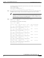
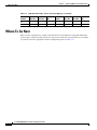
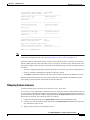
1. This document was not updated for the January 2005 release.
2. Some configuration and command information is included in this book for using the multiprotocol service module (MPSM-8-T1E1/MPSM-16-T1E1) in
a Cisco MGX 8230, MGX 8250, or MGX 8850 (PXM1) switch.
Cisco MGX 8800/8900 Series Software Configuration Guide
Release 5.1, Part Number OL-6482-01, Rev. A0, January 25, 2005
xxxvii
About This Guide
Documentation
Note
For the January 2005 product release, there are no new features for the Service Expansion Shelf (SES)
of the BPX switch and BPX WAN switching software. Therefore, documentation for these items was
not updated. Table 2 lists the most recent technical manuals and release notes for these products.
Table 2 also lists the latest documentation available for the Cisco MGX 8230, Cisco MGX 8250, and
Cisco MGX 8850 (PXM1) switches. These switches use the PXM1 processor card. Although there are
new features in MGX Release 1.3 for these switches, only the release notes were updated. And the
following books contain some information about configuring the MPSM-8-T1E1 and MPSM-16-T1E1
cards for use in these switches:
•
Cisco Circuit Emulation Services (CESM/MPSM) Configuration Guide and Command Reference
for MGX Switches, Release 5.1
•
Cisco Frame Relay Services (FRSM/MPSM) Configuration Guide and Command Reference for
MGX Switches, Release 5.1
•
Cisco ATM Services (AUSM/MPSM) Configuration Guide and Command Reference for MGX
Switches, Release 5.1
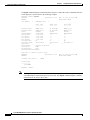
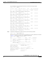
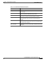
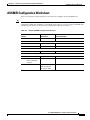
Table 3 lists the documents that ship with product.
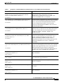
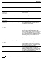
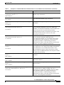
Table 4 contains alphabetized titles and descriptions of all the manuals and release notes listed in
Table 2.
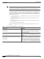
Table 3
Documents that Ship with Multiservice Switch Products
Document Title
Description
Guide to Cisco Multiservice Switch and Media Gateway
Documentation
Describes how to find the manuals and release notes that
support multiservice switches and network management
products. These documents are available only online. This
guide ships with product.
DOC-7814807=
Installation Warning Card
DOC-7812348=
Regulatory Compliance and Safety Information for Cisco
Multiservice Switch and Media Gateway Products (MGX,
BPX, and SES)
DOC-7814790=
Contains precautions that you should take before you
insert a card into a slot. This Warning Card ships with
product.
Provides regulatory compliance information, product
warnings, and safety recommendations for all the Cisco MGX
multiservice switches: MGX 8230, MGX 8250, MGX 8850
(PXM1), MGX 8850 (PXM45), MGX 8850 (PXM1E), MGX
8830 and MGX 8950. Also provides such information for the
MGX 8880 Media Gateway. This book ships with product.
Cisco MGX 8800/8900 Series Software Configuration Guide
xxxviii
Release 5.1, Part Number OL-6482-01, Rev. A0, January 25, 2005
About This Guide
Documentation
Table 4
Descriptions of Technical Manuals and Release Notes for Cisco Multiservice Switch Products
Document Title
Description
Cisco ATM and Frame Relay Services (MPSM-T3E3-155 and Provides software configuration procedures for provisioning
ATM and Frame Relay connections on the new
MPSM-16-T1E1) Configuration Guide and Command
MPSM-T3E3-155 multiprotocol service module. Also
Reference for MGX Switches, Release 5.1
describes all MPSM-T3E3-155 commands.
OL-6487-01
Cisco ATM Services (AUSM/MPSM) Configuration Guide
and Command Reference for MGX Switches, Release 5.1
OL-6479-01
Cisco ATM Services (AXSM) Configuration Guide and
Command Reference for MGX Switches, Release 5.1
OL-4548-01
Cisco Circuit Emulation Services (CESM/MPSM)
Configuration Guide and Command Reference for MGX
Switches, Release 5.1
OL-6481-01
Cisco Frame Relay Services (FRSM/MPSM) Configuration
Guide and Command Reference for MGX Switches, Release
5.1
OL-6480-01
Cisco MGX 8230 Edge Concentrator Installation and
Configuration, Release 1.1.3
Provides software configuration procedures for provisioning
connections and managing the AUSM cards supported in this
release. Also describes all AUSM commands. Includes
software configuration procedures for provisioning
connections and managing the MPSM-8-T1E1 card as an
AUSM card replacement.
Explains how to configure the AXSM cards and provides a
command reference that describes the AXSM commands in
detail. The AXSM cards covered in this manual are the
AXSM-XG, AXSM/A, AXSM/B, AXSM-E, and
AXSM-32-T1E1-E.
Provides software configuration procedures for provisioning
connections and managing the Circuit Emulation Service
Module (CESM) cards supported in this release. Also
describes all CESM commands. Includes software
configuration procedures for provisioning connections and
managing the MPSM-8-T1E1 card as a CESM card
replacement.
Provides software configuration procedures for provisioning
connections and managing the Frame Relay Service Module
(FRSM) cards supported in this release. Also describes all
FRSM commands. Includes software configuration
procedures for provisioning connections and managing the
MPSM-8-T1E1 card as an FRSM card replacement.
Provides installation instructions for the Cisco MGX 8230
edge concentrator.
DOC-7811215=
Cisco MGX 8230 Edge Concentrator Overview, Release 1.1.3 Describes the system components and function of the
Cisco MGX 8250 edge concentrator.
DOC-7812899=
Cisco MGX 8230 Multiservice Gateway Command Reference, Provides detailed information on the general command line
interface commands.
Release 1.1.3
DOC-7811211=
Cisco MGX 8230 Multiservice Gateway Error Messages,
Release 1.1.3
Provides error message descriptions and recovery
procedures.
DOC-78112113=
Cisco MGX 8250 Edge Concentrator Installation and
Configuration, Release 1.1.3
Provides installation instructions for the Cisco MGX 8250
edge concentrator.
DOC-7811217=
Cisco MGX 8800/8900 Series Software Configuration Guide
Release 5.1, Part Number OL-6482-01, Rev. A0, January 25, 2005
xxxix
About This Guide
Documentation
Table 4
Descriptions of Technical Manuals and Release Notes for Cisco Multiservice Switch Products (continued)
Document Title
Description
Cisco MGX 8250 Edge Concentrator Overview, Release 1.1.3 Describes the system components and function of the
Cisco MGX 8250 edge concentrator.
DOC-7811576=
Cisco MGX 8250 Multiservice Gateway Command Reference, Provides detailed information on the general command line
Release 1.1.3
interface commands.
DOC-7811212=
Cisco MGX 8250 Multiservice Gateway Error Messages,
Release 1.1.3
Provides error message descriptions and recovery
procedures.
DOC-7811216=
Cisco MGX 8800 Series Switch Command Reference, Release Provides detailed information on the general command line
for the Cisco MGX 8850 (PXM1), Cisco MGX 8250, and
1.1.3
Cisco MGX 8230 edge concentrators.
DOC-7811210=
Cisco MGX 8800 Series Switch System Error Messages,
Release 1.1.3
DOC-7811240=
Cisco MGX 8800/8900 Series Hardware Installation Guide,
Releases 2 - 5.1
OL-4545-01
Provides error message descriptions and recovery procedures
for Cisco MGX 8850 (PXM1), Cisco MGX 8250, and
Cisco MGX 8230 edge concentrators.
Describes how to install the Cisco MGX 8950, the
Cisco MGX 8850 (PXM1E/PXM45), the Cisco MGX
8850/B (PXM1E/PXM45), and the Cisco MGX 8830
switches. Also describes how to install the MGX 8880 Media
Gateway. This document explains what each switch does and
covers site preparation, grounding, safety, card installation,
and cabling. The Cisco MGX 8850 switch uses either a
PXM45 or a PXM1E controller card and provides support for
both serial bus-based and cell bus-based service modules.
The Cisco MGX 8830 switch uses a PXM1E controller card
and supports cell bus-based service modules. The Cisco
MGX 8950 supports only serial bus-based service modules.
The Cisco MGX 8880 uses a PXM45/C controller card, and
supports only serial bus-based service modules. This
hardware installation guide replaces all previous hardware
guides for these switches.
Cisco MGX 8800/8900 Series Software Configuration Guide, Describes how to configure the Cisco MGX 8880 Media
Gateway. Also describes how to configure Cisco MGX 8850
Release 5.1
(PXM1E), Cisco MGX 8850 (PXM45), the Cisco MGX
OL-6482-01
8850/B (PXM1E/PXM45), and Cisco MGX 8830 switches to
operate as ATM edge switches and the Cisco MGX 8950
switch to operate as a core switch. This guide also provides
some operation and maintenance procedures.
Cisco MGX 8800/8900 Series Command Reference, Release
5.1
OL-6483-01
Describes the PXM commands that are available in the CLI
of the Cisco MGX 8850 (PXM45), Cisco MGX 8850
(PXM1E), Cisco MGX 8950, and Cisco MGX 8830 switches.
Also describes the PXM commands that are available in the
CLI of the Cisco MGX 8880 Media Gateway.
Cisco MGX 8800/8900 Series Software Configuration Guide
xl
Release 5.1, Part Number OL-6482-01, Rev. A0, January 25, 2005
About This Guide
Documentation
Table 4
Descriptions of Technical Manuals and Release Notes for Cisco Multiservice Switch Products (continued)
Document Title
Description
Cisco MGX 8850 Edge Concentrator Installation and
Configuration, Release 1.1.3
Provides installation instructions for the Cisco MGX 8850
(PXM1) edge concentrator.
DOC-7811223=
Cisco MGX 8850 Multiservice Switch Overview, Release 1.1.3 Describes the system components and function of the
Cisco MGX 8850 (PXM1) edge concentrator.
OL-1154-01
Cisco MGX and Service Expansion Shelf Error Messages,
Release 5.1
Provides error message descriptions and recovery
procedures.
OL-6485-01
Cisco MGX Route Processor Module (RPM-XF) Installation
and Configuration Guide, Release 5.1
OL-6954-01
Cisco MGX Route Processor Module (RPM-PR) Installation
and Configuration Guide, Release 2.1
78-12510-02
Describes how to install and configure the Cisco MGX Route
Processor Module (RPM-XF) in the Cisco MGX 8850
(PXM45), Cisco MGX 8880 (PXM45), and Cisco MGX 8950
switch. Also provides site preparation procedures,
troubleshooting procedures, maintenance procedures, cable
and connector specifications, and basic Cisco IOS
configuration information.
Describes how to install and configure the Cisco MGX Route
Processor Module (RPM/B or RPM-PR) in the
Cisco MGX 8850 (PXM1), the Cisco MGX 8250, and the
Cisco MGX 8230 edge concentrators. Also provides site
preparation procedures, troubleshooting procedures,
maintenance procedures, cable and connector specifications,
and basic Cisco IOS configuration information.
OL-3847-01
Provides guidelines for planning a PNNI network that uses
Cisco MGX 8830, Cisco MGX 8850 (PXM45 and PXM1E),
Cisco MGX 8950, or Cisco BPX 8600 switches or the
MGX 8880 Media Gateway. When connected to a PNNI
network, each Cisco BPX 8600 Series switch requires an SES
for PNNI route processing.
Cisco Service Expansion Shelf Hardware Installation Guide,
Release 1
Provides instructions for installing and maintaining an SES
controller.
Cisco PNNI Network Planning Guide for MGX and SES
Products
DOC-786122=
Cisco SES PNNI Controller Command Reference, Release 3
DOC-7814260=
Cisco SES PNNI Controller Software Configuration Guide,
Release 3
Describes the commands used to configure and operate the
SES PNNI controller.
Describes how to configure, operate, and maintain the SES
PNNI controller.
DOC-7814258=
Cisco Voice Interworking Services (VISM) Configuration
Guide and Command Reference, Release 3.3
OL-5358-01
Describes how to install and configure the Voice
Interworking Service Module (VISM) in the Cisco
MGX 8830, Cisco MGX 8850 (PXM45), and Cisco MGX
8850 (PXM1E) multiservice switches. Provides site
preparation procedures, troubleshooting procedures,
maintenance procedures, cable and connector specifications,
and Cisco CLI configuration information.
Cisco MGX 8800/8900 Series Software Configuration Guide
Release 5.1, Part Number OL-6482-01, Rev. A0, January 25, 2005
xli
About This Guide
Documentation
Table 4
Descriptions of Technical Manuals and Release Notes for Cisco Multiservice Switch Products (continued)
Document Title
Description
Cisco Voice Switch Services (VXSM) Configuration and
Command Reference Guide for MGX Switches, Release 5.1
Describes the features and functions of the new Voice Switch
Service Module (VXSM) in the Cisco MGX 8880 Media
Gateway and in the Cisco MGX8850 (PXM45 and PXM1E)
multiservice switches. Also provides configuration
procedures, troubleshooting procedures, and Cisco CLI
configuration information.
OL-4625-01
Cisco WAN Manager Database Interface Guide, Release 15.1 Provides information about accessing the CWM Informix
database that is used to store information about the network
OL-6261-01
elements.
Cisco WAN Manager Installation Guide, Release 15.1
OL-6259-01
Cisco WAN Manager SNMP Service Agent, Release 15.1
OL-6260-01
Cisco WAN Manager User’s Guide, Release 15.1
OL-6257-01
Provides procedures for installing Release 15.1 of the CWM
network management system.
Provides information about the CWM Simple Network
Management Protocol service agent, an optional adjunct to
CWM that is used for managing Cisco WAN switches
through SNMP.
Describes how to use the CWM Release 15.1 software, which
consists of user applications and tools for network
management, connection management, network
configuration, statistics collection, and security management.
Note
Cisco Frame Relay Software Configuration Guide and
Command Reference for the Cisco MGX 8850 (PXM45)
FRSM-12-T3E3 Card, Release 3
The CWM interface now has built-in documentation
support in the form of online Help. On a PC, press F1
to access Help; on a UNIX workstation, press the
Help key. Alternatively, on either system you can
select Help from the main or popup menu.
Describes how to use the high-speed Frame Relay
(FRSM-12-T3E3) commands that are available in the CLI of
the Cisco MGX 8850 (PXM45) switch.
DOC-7810327=
Release Notes for Cisco MGX 8230, Cisco MGX 8250, and
Cisco MGX 8850 (PXM1) Switches, Release 1.3.10
OL-4539-01
Provides new feature, upgrade, and compatibility
information, as well as information about known and
resolved anomalies.
Release Notes for Cisco MGX 8850 (PXM1E/PXM45), Cisco Provides new feature, upgrade, and compatibility
MGX 8950, and Cisco MGX 8830 Switches, Release 5.1.00
information, as well as information about known and
resolved anomalies.
OL-6478-01
Release Notes for the Cisco MGX 8880 Media Gateway,
Release 5.1.00
Provides new feature and compatibility information, as well
as information about known and resolved anomalies.
OL-6493-01
Release Notes for Cisco MGX Route Processor Module
(RPM-PR) IOS Release 12.3(7)T3 for MGX Releases 1.3.10
and 5.0.10
Provides upgrade and compatibility information, as well as
information about known and resolved anomalies.
OL-7058-01
Cisco MGX 8800/8900 Series Software Configuration Guide
xlii
Release 5.1, Part Number OL-6482-01, Rev. A0, January 25, 2005
About This Guide
Obtaining Documentation
Table 4
Descriptions of Technical Manuals and Release Notes for Cisco Multiservice Switch Products (continued)
Document Title
Description
Provides upgrade and compatibility information, as well as
Release Notes for Cisco MGX Route Processor Module
(RPM-XF) IOS Release 12.3(2)T5 for PXM45-based Switches, information about known and resolved anomalies.
Release 5.0.00
OL-7059-01
Release Notes for the Cisco Voice Interworking Service
Module (VISM), Release 3.3.00
OL-5357-01
Release Notes for the Cisco Voice Switch Service Module
(VXSM), Release 5.1.00
OL-6224-01
Release Notes for Cisco WAN Manager, Release 15.1.00
OL-6495-01
Provides new feature, upgrade, and compatibility
information, as well as information about known and
resolved anomalies.
Provides new feature, upgrade, and compatibility
information, as well as information about known and
resolved anomalies.
Provides new feature, upgrade, and compatibility
information, as well as information about known and
resolved anomalies.
Obtaining Documentation
Cisco documentation and additional literature are available on Cisco.com. Cisco also provides several
ways to obtain technical assistance and other technical resources. These sections explain how to obtain
technical information from Cisco Systems.
Cisco.com
You can access the most current Cisco documentation at this URL:
http://www.cisco.com/univercd/home/home.htm
You can access the Cisco website at this URL:
http://www.cisco.com
You can access international Cisco websites at this URL:
http://www.cisco.com/public/countries_languages.shtml
Documentation DVD
Cisco documentation and additional literature are available in a Documentation DVD package, which
may have shipped with your product. The Documentation DVD is updated regularly and may be more
current than printed documentation. The Documentation DVD package is available as a single unit.
Registered Cisco.com users (Cisco direct customers) can order a Cisco Documentation DVD (product
number DOC-DOCDVD=) from the Ordering tool or Cisco Marketplace.
Cisco Ordering tool:
http://www.cisco.com/en/US/partner/ordering/
Cisco MGX 8800/8900 Series Software Configuration Guide
Release 5.1, Part Number OL-6482-01, Rev. A0, January 25, 2005
xliii
About This Guide
Documentation Feedback
Cisco Marketplace:
http://www.cisco.com/go/marketplace/
Ordering Documentation
You can find instructions for ordering documentation at this URL:
http://www.cisco.com/univercd/cc/td/doc/es_inpck/pdi.htm
You can order Cisco documentation in these ways:
•
Registered Cisco.com users (Cisco direct customers) can order Cisco product documentation from
the Ordering tool:
http://www.cisco.com/en/US/partner/ordering/
•
Nonregistered Cisco.com users can order documentation through a local account representative by
calling Cisco Systems Corporate Headquarters (California, USA) at 408 526-7208 or, elsewhere in
North America, by calling 1 800 553-NETS (6387).
Documentation Feedback
You can send comments about technical documentation to [email protected].
You can submit comments by using the response card (if present) behind the front cover of your
document or by writing to the following address:
Cisco Systems
Attn: Customer Document Ordering
170 West Tasman Drive
San Jose, CA 95134-9883
We appreciate your comments.
Cisco Product Security Overview
Cisco provides a free online Security Vulnerability Policy portal at this URL:
http://www.cisco.com/en/US/products/products_security_vulnerability_policy.html
From this site, you can perform these tasks:
•
Report security vulnerabilities in Cisco products.
•
Obtain assistance with security incidents that involve Cisco products.
•
Register to receive security information from Cisco.
A current list of security advisories and notices for Cisco products is available at this URL:
http://www.cisco.com/go/psirt
If you prefer to see advisories and notices as they are updated in real time, you can access a Product
Security Incident Response Team Really Simple Syndication (PSIRT RSS) feed from this URL:
http://www.cisco.com/en/US/products/products_psirt_rss_feed.html
Cisco MGX 8800/8900 Series Software Configuration Guide
xliv
Release 5.1, Part Number OL-6482-01, Rev. A0, January 25, 2005
About This Guide
Obtaining Technical Assistance
Reporting Security Problems in Cisco Products
Cisco is committed to delivering secure products. We test our products internally before we release
them, and we strive to correct all vulnerabilities quickly. If you think that you might have identified a
vulnerability in a Cisco product, contact PSIRT:
Tip
•
Emergencies — [email protected]
•
Nonemergencies — [email protected]
We encourage you to use Pretty Good Privacy (PGP) or a compatible product to encrypt any sensitive
information that you send to Cisco. PSIRT can work from encrypted information that is compatible with
PGP versions 2.x through 8.x.
Never use a revoked or an expired encryption key. The correct public key to use in your correspondence
with PSIRT is the one that has the most recent creation date in this public key server list:
http://pgp.mit.edu:11371/pks/lookup?search=psirt%40cisco.com&op=index&exact=on
In an emergency, you can also reach PSIRT by telephone:
•
1 877 228-7302
•
1 408 525-6532
Obtaining Technical Assistance
For all customers, partners, resellers, and distributors who hold valid Cisco service contracts, Cisco
Technical Support provides 24-hour-a-day, award-winning technical assistance. The Cisco Technical
Support Website on Cisco.com features extensive online support resources. In addition, Cisco Technical
Assistance Center (TAC) engineers provide telephone support. If you do not hold a valid Cisco service
contract, contact your reseller.
Cisco Technical Support Website
The Cisco Technical Support Website provides online documents and tools for troubleshooting and
resolving technical issues with Cisco products and technologies. The website is available 24 hours a day,
365 days a year, at this URL:
http://www.cisco.com/techsupport
Access to all tools on the Cisco Technical Support Website requires a Cisco.com user ID and password.
If you have a valid service contract but do not have a user ID or password, you can register at this URL:
http://tools.cisco.com/RPF/register/register.do
Note
Use the Cisco Product Identification (CPI) tool to locate your product serial number before submitting
a web or phone request for service. You can access the CPI tool from the Cisco Technical Support
Website by clicking the Tools & Resources link under Documentation & Tools. Choose Cisco Product
Identification Tool from the Alphabetical Index drop-down list, or click the Cisco Product
Identification Tool link under Alerts & RMAs. The CPI tool offers three search options: by product ID
Cisco MGX 8800/8900 Series Software Configuration Guide
Release 5.1, Part Number OL-6482-01, Rev. A0, January 25, 2005
xlv
About This Guide
Obtaining Technical Assistance
or model name; by tree view; or for certain products, by copying and pasting show command output.
Search results show an illustration of your product with the serial number label location highlighted.
Locate the serial number label on your product and record the information before placing a service call.
Submitting a Service Request
Using the online TAC Service Request Tool is the fastest way to open S3 and S4 service requests. (S3
and S4 service requests are those in which your network is minimally impaired or for which you require
product information.) After you describe your situation, the TAC Service Request Tool provides
recommended solutions. If your issue is not resolved using the recommended resources, your service
request is assigned to a Cisco TAC engineer. The TAC Service Request Tool is located at this URL:
http://www.cisco.com/techsupport/servicerequest
For S1 or S2 service requests or if you do not have Internet access, contact the Cisco TAC by telephone.
(S1 or S2 service requests are those in which your production network is down or severely degraded.)
Cisco TAC engineers are assigned immediately to S1 and S2 service requests to help keep your business
operations running smoothly.
To open a service request by telephone, use one of the following numbers:
Asia-Pacific: +61 2 8446 7411 (Australia: 1 800 805 227)
EMEA: +32 2 704 55 55
USA: 1 800 553-2447
For a complete list of Cisco TAC contacts, go to this URL:
http://www.cisco.com/techsupport/contacts
Definitions of Service Request Severity
To ensure that all service requests are reported in a standard format, Cisco has established severity
definitions.
Severity 1 (S1)—Your network is “down,” or there is a critical impact to your business operations. You
and Cisco will commit all necessary resources around the clock to resolve the situation.
Severity 2 (S2)—Operation of an existing network is severely degraded, or significant aspects of your
business operation are negatively affected by inadequate performance of Cisco products. You and Cisco
will commit full-time resources during normal business hours to resolve the situation.
Severity 3 (S3)—Operational performance of your network is impaired, but most business operations
remain functional. You and Cisco will commit resources during normal business hours to restore service
to satisfactory levels.
Severity 4 (S4)—You require information or assistance with Cisco product capabilities, installation, or
configuration. There is little or no effect on your business operations.
Cisco MGX 8800/8900 Series Software Configuration Guide
xlvi
Release 5.1, Part Number OL-6482-01, Rev. A0, January 25, 2005
About This Guide
Obtaining Additional Publications and Information
Obtaining Additional Publications and Information
Information about Cisco products, technologies, and network solutions is available from various online
and printed sources.
•
Cisco Marketplace provides a variety of Cisco books, reference guides, and logo merchandise. Visit
Cisco Marketplace, the company store, at this URL:
http://www.cisco.com/go/marketplace/
•
Cisco Press publishes a wide range of general networking, training and certification titles. Both new
and experienced users will benefit from these publications. For current Cisco Press titles and other
information, go to Cisco Press at this URL:
http://www.ciscopress.com
•
Packet magazine is the Cisco Systems technical user magazine for maximizing Internet and
networking investments. Each quarter, Packet delivers coverage of the latest industry trends,
technology breakthroughs, and Cisco products and solutions, as well as network deployment and
troubleshooting tips, configuration examples, customer case studies, certification and training
information, and links to scores of in-depth online resources. You can access Packet magazine at
this URL:
http://www.cisco.com/packet
•
iQ Magazine is the quarterly publication from Cisco Systems designed to help growing companies
learn how they can use technology to increase revenue, streamline their business, and expand
services. The publication identifies the challenges facing these companies and the technologies to
help solve them, using real-world case studies and business strategies to help readers make sound
technology investment decisions. You can access iQ Magazine at this URL:
http://www.cisco.com/go/iqmagazine
•
Internet Protocol Journal is a quarterly journal published by Cisco Systems for engineering
professionals involved in designing, developing, and operating public and private internets and
intranets. You can access the Internet Protocol Journal at this URL:
http://www.cisco.com/ipj
•
World-class networking training is available from Cisco. You can view current offerings at
this URL:
http://www.cisco.com/en/US/learning/index.html
Cisco MGX 8800/8900 Series Software Configuration Guide
Release 5.1, Part Number OL-6482-01, Rev. A0, January 25, 2005
xlvii
About This Guide
Obtaining Additional Publications and Information
Cisco MGX 8800/8900 Series Software Configuration Guide
xlviii
Release 5.1, Part Number OL-6482-01, Rev. A0, January 25, 2005
C H A P T E R
1
Preparing for Configuration
This document provides general configuration information and procedures for the
MGX 8850 (PXM1E/PXM45), MGX 8950, and MGX 8830 switches. Use this document after you have
installed your switch according to the instructions in the Cisco MGX 8800/8900 Hardware Installation
Guide, Releases 2 - 5.1.
Use this document in conjunction with the Cisco MGX 8800/8900 Series Command Reference, Release
5.1. The command reference manual contains detailed information about the commands used to
configure and display information about the switch.
Note
If your MGX switch will be part of a PNNI network, you can use the Cisco PNNI Network Planning
Guide for MGX and SES Products to help you define the ATM and PNNI configuration parameters that
you can configure using the procedures in the this guide.
This document tells you how to do the following tasks:
Note
•
Complete basic switch configuration tasks such as setting the time, configuring administrator
access, and configuring the ATM address.
•
Prepare all cards and lines for operation in the switch.
•
Provision communication links on PXM1E controller cards.
•
Perform general switch operating procedures.
•
Perform maintenance procedures, such as replacing cards.
•
Perform software upgrades for the cards in your switch.
•
Perform switch-specific PNNI procedures.
This document does not cover link provisioning for any cards except for PXM1E. To provision links on
the specific service modules, refer to the appropriate service module software configuration guide (see
Table 1-1).
Cisco MGX 8800/8900 Series Software Configuration Guide
Release 5.1, Part Number OL-6482-01, Rev. A0, January 25, 2005
1-1
Chapter 1
Table 1-1
Preparing for Configuration
Card-specific Configuration Guides
Service Module
Software Configuration Guide Title
AUSM/B and MPSM Cisco ATM Services (AUSM/MPSM) Configuration Guide and Command
cards
Reference for MGX Switches, Release 5.1
AXSM cards
Cisco ATM Services (AXSM) Configuration Guide and Command Reference for
MGX Switches, Release 5
CESM and MPSM
cards
Cisco Circuit Emulation Services (CESM/MPSM) Configuration Guide and
Command Reference for MGX Switches, Release 5.1
FRSM and MPSM
cards
Cisco Frame Relay Services (FRSM/MPSM) Configuration Guide and
Command Reference for MGX Switches, Release 5.1
FRSM12
Frame Relay Software Configuration Guide and Command Reference for the
Cisco MGX 8850 FRSM12 Card, Release 3
MPSM-16-T1E1 and Cisco ATM and Frame Relay Services (MPSM-T3E3-155 and MPSM-16-T1E1)
MPSM-T3E3-155
Configuration Guide and Command Reference for MGX Switches, Release 5.1
RPM-PR cards
Cisco MGX Route Processor Module (RPM-PR) Installation and Configuration
Guide, Release 2.1
RPM-XF cards
Cisco MGX Route Processor Module (RPM-XF) Installation and Configuration
Guide, Release 5.1
VISM-PR cards
Cisco Voice Interworking Services (VISM) Configuration Guide and Command
Reference, Release 3.3
VXSM cards
Cisco Voice Switch Services (VXSM) Configuration Guide and Command
Reference for MGX Switches, Release 5
After your switch is configured and your links are provisioned, you can use this document as a reference
for operational, maintenance, and upgrade procedures.
Keep the following statements in mind as you read this document:
•
The generic term “MGX switch” refers to all MGX switches that support Release 5.1 software
(listed in Table 1-3). If a procedure or step is specific to only one or two of the MGX switches, it
will be specified in the text.
•
The generic term “PXM” refers to both the PXM45 card and the PXM1E card. If a procedure or step
is specific to only one of the PXMs, it will be specified in the text.
•
Throughout this guide, the term PXM45 is a generic term used to refer to PXM45/A, PXM45/B, and
PXM45/C cards.
•
On MGX switches, the PXM card is the controller card that controls the other cards on the switch.
The other cards on the switch are called service modules.
•
Throughout this guide, the term AXSM is used to refer to all the AXSM cards. If a procedure or
paragraph applies to only a specific AXSM card or specific AXSM cards, it will be specified as such.
The first release of the AXSM cards are labeled “AXSM,” but are often referred to as AXSM/A
cards. The second release of AXSM cards are labeled and called AXSM/B cards. Other AXSM
models include the AXSM-E and AXSM-XG card families.
Cisco MGX 8800/8900 Series Software Configuration Guide
1-2
Release 5.1, Part Number OL-6482-01, Rev. A0, January 25, 2005
Chapter 1
Preparing for Configuration
Changes to this Document
•
Cisco MGX Release 5.1 software supports a number of single-height service modules (listed in
Table 1-3) that were originally designed to operate in Cisco MGX 8850 (PXM1) switches. These
service modules use the cell bus to transport traffic to other services modules or PXM uplinks and
are commonly referred to as cell bus service modules (CBSMs). (The CBSMs have also been called
Narrow Band Service Modules (NBSMs) in Cisco documentation.)
The CBSM term is used to refer to this class of cards as a whole. CBSM cards include the AUSM,
CESM, FRSM, MPSM, RPM, RPM-PR, and VISM card families.
Note
•
The AXSM , FRSM-12-T3E3 , RPM-XF, and VXSM cards are not CBSMs. They are full-height
cards that communicate with the PXM45 and other service modules through the serial bus.
The MGX switch does not support synchronization with daylight savings time even if the node is
connected to the SNTP server and is receiving UTC.
Once you have installed your switch and completed the general configuration procedures described in
this guide, refer to the service module documentation for information on provisioning and managing
individual services such as ATM, circuit emulation, Frame Relay, and IP.
This chapter introduces the Cisco MGX multiservice switches and common switch topologies, provides
an overview of the configuration process, and presents guidelines for collecting the information you will
need to complete the configuration.
Changes to this Document
Table 1-2 summarizes the changes made to this document since Release 5.
Table 1-2
Changes to This Guide Since Release 5
Section
Status
All
New/Modified Updated where applicable throughout document to support changes
resulting from Release 5.1 features. These features are summarixed in
the“Documentation” preface section.
All
Modified
Description
Numerous other editorial and technical edits throughout entire document.
Cisco MGX Switch Features
The Cisco MGX multiservice switches provide support for the following features:
•
Permanent virtual circuits (PVCs)
•
Permanent virtual paths (PVPs)
•
Soft permanent virtual paths (SPVPs)
•
Soft permanent virtual circuits (SPVCs)
•
Switched virtual circuits (SVCs)
•
Switched virtual paths (SVPs)
The following table identifies the capabilities supported by each of the Cisco MGX switches and the
MGX 8880 Media Gateway.
Cisco MGX 8800/8900 Series Software Configuration Guide
Release 5.1, Part Number OL-6482-01, Rev. A0, January 25, 2005
1-3
Chapter 1
Preparing for Configuration
Cisco MGX Switch Features
Table 1-3
Cisco MGX 8850 (PXM1E/PXM45), Cisco MGX 8850/B, Cisco MGX 8950, Cisco MGX 8830, Cisco MGX 8830/B,
and Cisco MGX 8880 Capabilities
Cisco MGX Model
Feature
8850 (PXM1E) 8850 (PXM45) 8850/B
Total Number of
Slots
2 double height slots and 28 single height slots.
Slots Reserved for
Processor Cards
2 double height slots.
Slots Reserved for
SRM Cards
4 single height slots
Slots Reserved for
XM-60 Cards
—
Slots for Service
Modules
24 single height slots, or 12 double height slots, or a
combination of both.1
8 single height slots, or 4 double height
slots, or a combination of both.1
24 single height slots, or 12 double height
slots, or a combination of both.1
Height
29.75 inches
14 inches
29.75 inches
Width
17.72 inches
Depth
21.5 inches
—
—
8830
8830/B
—
8880
8950
2 double height
slots and 10 single
height slots.
2 double height slots and 28 single height
slots.
2 single height
slots
4 single height
slots
—
—
—
4 single height slots
Physical Attributes
Services
Local Switching
Yes
PNNI Routing
Yes
IGX Feeder
Support
Yes
MGX 8230,
MGX 8250 and
MGX 8850 (PXM1)
Feeder Support
Yes
IMA
Yes.
PXM1E-16-T1E1
AUSM/B
MPSM-8-T1E1
MPSM-16-T1E1
MPSM-T3E3-155
Multilink Frame
Relay
MPSM-T3E3-155
Switching
Capacity
1.2 Gbps
Multilink PPP
includes all the
PPP features
Yes
No
Yes
AXSM-32-T1E1-E
MPSM-16-T1E1
MPSM-T3E3-155
45 Gbps
Yes.
PXM1E-16-T1E1
AUSM/B
MPSM-8-T1E1
MPSM-16-T1E1
MPSM-T3E3-155
1.2 Gbps
Yes
PXM1E-16-T1E1
AUSM/B
MPSM-8-T1E1
MPSM-16-T1E1
MPSM-T3E3-155
1.2 Gbps
Yes
MPSM-8-T1E1
MPSM-16-T1E1
MPSM-T3E3-155
45 Gbps
Yes
AXSM-32-T1E1-E
No
—
—
45 Gbps
240 Gbps
—
—
Cisco MGX 8800/8900 Series Software Configuration Guide
1-4
Release 5.1, Part Number OL-6482-01, Rev. A0, January 25, 2005
Chapter 1
Preparing for Configuration
Cisco MGX Switch Features
Table 1-3
Cisco MGX 8850 (PXM1E/PXM45), Cisco MGX 8850/B, Cisco MGX 8950, Cisco MGX 8830, Cisco MGX 8830/B,
and Cisco MGX 8880 Capabilities (continued)
Cisco MGX Model
Feature
8850 (PXM1E) 8850 (PXM45) 8850/B
8830
8830/B
8880
8950
Trunk/Port Interfaces
T1/E1
AUSM-8E1/B
AUSM-8T1/B
CESM-8E1
CESM-8T1/B
FRSM-8E1
FRSM-8E1-C
FRSM-8T1
FRSM-8T1-C
MPSM-8-T1E1
MPSM-16-T1E1
PXM1E-16-T1E1
VISM-PR-8E1
VISM-PR-8T1
AXSM-32-T1E1-E
CESM-8E12
CESM-8T13
CESM-8T1/B2
FRSM-8E12
FRSM-8E1-C2
FRSM-8T12
FRSM-8T1-C2
MPSM-8-T1E1
MPSM-16-T1E1
VISM-PR-8E1
VISM-PR-8T1
VXSM-48-T1E1
MPSM-8-T1E1
MPSM-16-T1E1
VISM-PR-8E1
VISM-PR-8T1
AUSM-8E1/B
AUSM-8T1/B
CESM-8E1
CESM-8T1/B
FRSM-8E1
FRSM-8E1-C
FRSM-8T1
FRSM-8T1-C
MPSM-8-T1E1
MPSM-16-T1E1
PXM1E-16-T1E1
VISM-PR-8E1
VISM-PR-8T1
MPSM-8-T1E1
MPSM-16-T1E1
VISM-PR-8E1
VISM-PR-8T1
AXSM-32-T1E1-E
VISM-PR-8E1
VISM-PR-8T1
VXSM-48-T1E1
—
T3/E3
FRSM-2CT3
FRSM-2T3E3
MPSM-T3E3-155
PXM1E-8T3/E3
PXM-COMBO
SRM-3T3/C
SRME/B4
AXSM-16-E3
AXSM-16-E3/B
AXSM-16-E3-E
AXSM-16-T3
AXSM-16-T3/B
AXSM-16-T3
FRSM-2CT32
FRSM12-T3E3
MPSM-T3E3-155
SRM-3T3/C2
SRME/B2
SRME
AXSM-16-E3
AXSM-16-E3/B
AXSM-16-E3-E
AXSM-16-T3
AXSM-16-T3/B
AXSM-16-T3-E
FRSM-2CT32
MPSM-T3E3-155
SRME/B2,4
FRSM-2CT3
FRSM-2T3E3
MPSM-T3E3-155
PXM1E-8T3/E3
PXM-COMBO
SRM-3T3/C
SRME
SRME/B4
MPSM-T3E3-155
AXSM-16-T3- E
AXSM-16-E3- E
SRME/B2, 4
AXSM-16-E3/B
AXSM-16-E3-E
AXSM-16-T3/B
AXSM-16-T3-E
SRME/B24
AXSM-16-T3/B
AXSM-16-E3/B
OC-3/STM-1
MPSM-T3E3-155
PXM-COMBO
PXM1E-4-155
PXM1E-8-155
SRME5
SRME/B5
AXSM-8-155-E
AXSM-16-155
AXSM-16-155/B
AXSM-16-155-XG
MPSM-T3E3-155
SRME
SRME/B5
VXSM-4-155
AXSM-8-155-E
AXSM-16-155
AXSM-16-155/B
AXSM-16-155-XG
MPSM-T3E3-155
SRME/B5
VXSM-4-155
MPSM-T3E3-155
PXM-COMBO
PXM1E-4-155
PXM1E-8-155
SRME5
SRME/B5
AXSM-16-155-XG
AXSM-8-155-E
AXSM-16-155/B
VXSM-4-155
AXSM-16-155/B
AXSM-16-155-XG6, 7
OC-12c/STM-4
—
AXSM-4-622
AXSM-2-622-E
AXSM-4-622/B
AXSM-4-622-XG
—
AXSM-2-622-E
AXSM-2-622-E
AXSM-4-622/B
AXSM-4-622/B
OC-48c/STM-16
—
AXSM-1-2488
AXSM-1-2488/B
AXSM-1-2488/B
—
—
AXSM-1-2488/B
AXSM-1-2488/B
AXSM-4-2488-XG6
OC-192c/STM-64
—
—
—
—
—
—
AXSM-1-9953-XG6
HSSI
FRSM-HS2/B
FRSM-HS2/B2
FRSM-HS2/B2
FRSM-HS2/B
—
—
—
Supported Controller Cards
PXM1E
Yes
—
—
Yes
—
—
—
PXM45
—
Yes
Yes
—
—
—
—
PXM45/B
—
Yes
Yes
—
—
—
Yes
PXM45/C
—
Yes
Yes
—
Yes
Yes
Yes
Yes
Yes
Yes
Yes
Yes
Yes
Supported Routing Protocols
PNNI
Yes
Cisco MGX 8800/8900 Series Software Configuration Guide
Release 5.1, Part Number OL-6482-01, Rev. A0, January 25, 2005
1-5
Chapter 1
Preparing for Configuration
Cisco MGX Switch Features
Table 1-3
Cisco MGX 8850 (PXM1E/PXM45), Cisco MGX 8850/B, Cisco MGX 8950, Cisco MGX 8830, Cisco MGX 8830/B,
and Cisco MGX 8880 Capabilities (continued)
Cisco MGX Model
Feature
MPLS
8850 (PXM1E) 8850 (PXM45) 8850/B
8
8830
8830/B
8880
8950
—
Yes
Yes
—
—
Yes
Yes
AUSM-8E1/B
AUSM-8T1/B
MPSM-8-T1E1
MPSM-16-T1E1
MPSM-T3E3-155
PXM1E
All AXSM
MPSM-T3E3-155
MPSM-16-T1E1
All AXSM
MPSM-T3E3-155
AUSM-8E1/B
AUSM-8T1/B
MPSM-8-T1E1
MPSM-16-T1E1
MPSM-T3E3-155
PXM1E
AXSM-16-155-XG
AXSM-2-622-E
AXSM-16-T3E3-E
MPSM-8-T1E1
MPSM-16-T1E1
MPSM-T3E3-155
All AXSM/B
AXSM-E
All AXSM-XG
All AXSM/B
Frame Relay
FRSM-2CT3
FRSM-2T3E3
FRSM-8E1
FRSM-8E1-C
FRSM-8T1
FRSM-8T1-C
FRSM-HS2/B
MPSM-8-T1E1
MPSM-16-T1E1
MPSM-T3E3-155
FRSM-2CT32
FRSM-8E12
FRSM-8E1-C2
FRSM-8T12
FRSM-8T1-C2
FRSM-12-T3E32
FRSM-HS2/B2
MPSM-8-T1E1
MPSM-16-T1E1
MPSM-T3E3-155
FRSM-2CT32
FRSM-HS2/B2
MPSM-8-T1E1
MPSM-16-T1E1
MPSM-T3E3-155
FRSM-2CT3
FRSM-2T3E3
FRSM-8E1
FRSM-8E1-C
FRSM-8T1
FRSM-8T1-C
FRSM-HS2/B
MPSM-8-T1E1
MPSM-16-T1E1
MPSM-T3E3-155
MPSM-T3E3-155
MPSM-16-T1E1
—
—
Automatic
Protection
Switching
Yes.
(on PXM1E and
SRME)
Yes
(on AXSM and
SRME)
Yes.
(on PXM1E and
SRME)
Yes
(on PXM1E and
SRME)
Yes
(on AXSM and
SRME/B)
Yes
(on AXSM and
SRME)
Yes
(on AXSM)
Circuit Emulation
CESM-8E1
CESM-8T1/B
MPSM-8-T1E1
CESM-8E12
CESM-8T13
CESM-8T1/B2
MPSM-8-T1E1
MPSM-8-T1E1
CESM-8E1
CESM-8T1/B
MPSM-8-T1E1
MPSM-8-T1E1
—
—
Voice
VISM-PR-8E1
VISM-PR-8T1
VISM-PR-8E1
VISM-PR-8T1
VXSM-4-155
VXSM-48-T1E1
VISM-PR-8E1
VISM-PR-8T1
VXSM-4-155
VXSM-48-T1E1
VISM-PR-8E1
VISM-PR-8T1
VISM-PR-8E1
VISM-PR-8T1
VISM-PR-8E1
VISM-PR-8T1
VXSM-4-155
VXSM-48-T1E1
—
IP
RPM-PR
RPM-PR
RPM-XF
RPM-PR
RPM-XF
RPM-PR
RPM-PR
RPM-PR
RPM-XF
RPM-PR
RPM-XF
Service Resource
Module (SRM)
SRM-3T3/C
SRME5
SRME/B
SRM-3T3/C2
SRME5
SRME/B
SRME/B
SRM-3T3/C
SRME5
SRME/B
SRME/B
SRME/B
—
1:1 Card
Redundancy
See Tabl e 4.1 in Cisco MGX 8800/8900 Hardware Installation Guide, Releases 2 - 5.1.
is footnote 8 a true
statement
Supported Services
ATM services
MPSM-16-T1E1
1:N Card
Redundancy
APS Line
Redundancy
Bulk Distribution
Bit Error Rate
Testing (BERT)
Supported through SRM cards for AUSM, CESM, FRSM, and VISM-PR T1/E1
cards. Also supported on MPSM-8-T1E1 (with or without SRM).
All MPSM
SRME/B card (for
VISM-PR T1/E1)
—
UNI/NNI
All FRSM
All AUSM/B
All MPSM
All AXSM
All MPSM
All AXSM
All VXSM
All AXSM
All FRSM
All AUSM/B
All MPSM
All FRSM
All AUSM/B
All MPSM
All FRSM
All AUSM/B
All MPSM
Cisco MGX 8800/8900 Series Software Configuration Guide
1-6
Release 5.1, Part Number OL-6482-01, Rev. A0, January 25, 2005
Chapter 1
Preparing for Configuration
Typical Topologies
Table 1-3
Cisco MGX 8850 (PXM1E/PXM45), Cisco MGX 8850/B, Cisco MGX 8950, Cisco MGX 8830, Cisco MGX 8830/B,
and Cisco MGX 8880 Capabilities (continued)
Cisco MGX Model
Feature
8850 (PXM1E) 8850 (PXM45) 8850/B
SPVCs
All PXM1E
All AUSM
All AXSM
All CESM
All FRSM
All MPSM
All PXM1E
All RPM
All AUSM
All AXSM
All CESM
All FRSM
All MPSM
All PXM1E
All RPM
All AUSM
All AXSM
All CESM
All FRSM
All MPSM
All PXM1E
All RPM
All AUSM
All AXSM
All CESM
All FRSM
All MPSM
All PXM1E
All RPM
All AUSM
All AXSM
All CESM
All FRSM
All MPSM
All PXM1E
All RPM
All AXSM
All RPM
All AXSM
All RPM
SVCs
All PXM1E cards.
Supported on all
AXSM cards.
All PXM1E
All PXM1E
All PXM1E
All AXSM
All AXSM
Yes
Yes
Yes
Yes
8830
MPSM-16-T1E1
Closed User
Groups (CUGs)
8880
8950
MPSM-16-T1E1
MPSM-155-T3E3
Yes
8830/B
MPSM-155-T3E3
Yes
Yes
1.
Single-height and double-height cards can be mixed in a chassis if the switch model supports both types. Double-height cards require two single card slots.
2.
Supported only on PXM45/B and PXM45/C cards.
3.
Supported only on PXM45/B and PXM45/C cards. Although the PXM45/B can support CESM-8T1 cards, Cisco recommends using the CESM-8T1/B.
4.
SRME/B cards do not support E3 ports.
5.
SRME APS line redundancy is only supported on PXM45/B and PXM45/C.
6.
You must have four XM-60 cards installed on your Cisco MGX 8950 switch before you install any AXSM-XG cards.
7.
Supported only on Release 5 switches.
8.
For MGX 8850 (PXM45) and MGX 8950 switches, MPLS and PNNI can be used simultaneously on the same switch and on the same link.
Table 1-4 illustrates the differences between the PXM45/A, PXM45/B, and PXM45/C cards.
.
Table 1-4
Differences between PXM 45 Cards
PXM451
Feature
PXM45/B
PXM45/C
Maximum number of UNI/NNI interfaces per node supported 192
4,000
4,000
Maximum number of preferred routes supported
5,000
5,000
10,000
Maximum number of narrowband connections supported
N/A
27 k
27 k
Maximum number of SPVC/SVC connections supported
250 k
250 k
250k
Maximum number of PNNI links supported
100
100
128
1. The PXM45 is sometimes called the PXM45/A and is not supported in Release 5.1 software.
Typical Topologies
Release 5.1 of the MGX 8850 (PXM45), Cisco MGX 8850/B, and MGX 8950 switches support the
following topologies:
•
Core switch
•
Multiservice edge aggregation
•
DSL edge aggregation
Cisco MGX 8800/8900 Series Software Configuration Guide
Release 5.1, Part Number OL-6482-01, Rev. A0, January 25, 2005
1-7
Chapter 1
Preparing for Configuration
Typical Topologies
Release 5.1 of the MGX 8850 (PXM1E), MGX 8830, and Cisco 8830/B switches supports the following
topologies:
•
Multiservice edge aggregation
•
DSL edge aggregation
Core Switch
Figure 1-1 shows the switch operating in a core switch topology.
Figure 1-1
Core Switch Topology
Cisco
MGX 8850
(PXM45)
38410
Core ATM network
In the core switch topology, the switch works with other ATM switches to transfer broadband ATM
traffic from one ATM edge device to another. The core acts like a freeway, and the edge devices act like
freeway on-ramps.
Note
Typically, MGX 8850 (PXM45), MGX 8850/B, MGX 8830/B, and MGX 8950 switches are deployed in
the network core, while MGX 8830 and MGX 8850 (PXM1E) and the MGX 8880 Media Gateway are
deployed at the network edge.
Typically, core edge nodes communicate with multiple external nodes over relatively slow broadband
trunks such as DS3, OC-3, and STM-1 trunks. The internal core node communicates with other core
nodes using relatively fast links such as OC-12, OC-48, and STM-16 trunks.
Cisco MGX 8800/8900 Series Software Configuration Guide
1-8
Release 5.1, Part Number OL-6482-01, Rev. A0, January 25, 2005
Chapter 1
Preparing for Configuration
Typical Topologies
Multiservice Edge Aggregation
Figure 1-2 shows an MGX switch operating in a multiservice edge aggregation topology.
Figure 1-2
Multiservice Edge Aggregation Topology
ATM router
(Cisco or third-party)
Cisco
MGX 8850
(PXM1E)
Core ATM
network
ATM edge devices
(Cisco or third-party)
UNI or
NNI
Voice
ATM data
Cisco
MGX 8850
(PXM1)
Broadband trunks
38411
Frame data
The MGX 8850 (PXM1) node in Figure 1-2 is called a feeder node. In the multiservice edge aggregation
topology, the feeder node is co-located with other ATM equipment and communicates with one or more
core switches at remote locations.
The switch aggregates the traffic from local ATM devices and packages it for high-speed
communications over the core. MGX 8850 (PXM1E/PXM45) and MGX 8830 switches support feeder
connections from MGX 8230, MGX 8250, MGX 8850 (PXM1), and Cisco IGX nodes.
Typically, multiservice edge nodes communicate with colocated ATM devices over relatively slow
broadband trunks such as DS3 and E3 trunks. The multiservice edge node communicates with core nodes
using relatively fast links such as OC-12, OC-48, and STM-16 trunks.
Cisco MGX edge nodes also support virtual trunks as shown in Figure 1-3.
Cisco MGX 8800/8900 Series Software Configuration Guide
Release 5.1, Part Number OL-6482-01, Rev. A0, January 25, 2005
1-9
Chapter 1
Preparing for Configuration
Typical Topologies
Figure 1-3
Virtual Trunk Topology
Private
switch B
A
Edge
switch 2
Edge
switch 1
Core ATM
network
Private
switch A
A
Private
switch C
SPVP
B
B
Edge
switch 3
Legend
Physical line
46508
Virtual trunk
SPVP
A virtual trunk provides a private virtual network path through an independent network such as a public
ATM network. Using virtual trunks, Company A can establish a private virtual path between two sites
using a public ATM network that supports this feature.
From Company A’s point of view, it has a private virtual path between the two sites that can support
multiple virtual circuits (VCs). Company A’s network topology is completely private, as all
communications are simply passed between edge devices, with no need for translation or routing.
To accomplish this configuration, the virtual trunk supports the Service Specific Connection Oriented
Protocol (SSCOP) (virtual channel identifier [VCI = 5]), Private Network-to-Network Interface (PNNI)
(VCI = 18) and Integrated Local Management Interface (ILMI) (VCI = 16) signaling protocols.
Figure 1-3 shows two virtual trunks, Virtual Trunk A and Virtual Trunk B. At Private Switch A, both
virtual trunks use the same line to connect to the core ATM network. Within the core ATM network, soft
virtual permanent paths (SPVPs) are defined to enable direct communications between the core edge
nodes. The result is that Private Switch A has virtual trunks to Private Switches B and C and
communicates with them as though they were directly connected.
Cisco MGX 8800/8900 Series Software Configuration Guide
1-10
Release 5.1, Part Number OL-6482-01, Rev. A0, January 25, 2005
Chapter 1
Preparing for Configuration
Configuration Overview
DSL Aggregation
Figure 1-4 shows an MGX switch operating in a Digital Subscriber Line (DSL) edge aggregation
topology.
Figure 1-4
DSL Edge Aggregation Topology
DSL lines
38412
Core ATM
network
DSLAMs
In the DSL edge aggregation topology, the switch is colocated with Digital Subscriber Line Access
Multiplexers (DSLAMs) and communicates with one or more core switches at remote locations. The
switch aggregates the DSL traffic from multiple DSLAMs and packages it for high-speed
communications over the core.
Typically, DSL edge nodes communicate with colocated DSLAMs over relatively slower broadband
trunks such as DS3 and E3 trunks. The DSL edge node communicates with core nodes using relatively
faster links such as OC-3, OC-12, and OC-48 trunks.
Configuration Overview
Switch configuration is easier if you are familiar with the overall configuration process. To configure
and start up the switch, you need to do some or all of the following tasks:
•
Collect information you will need during the configuration process
•
Configure general switch features
•
Configure the physical connections to other devices
•
Provision ATM connections
•
Enable PNNI call routing
The sections that follow describe how to collect or create the information you need to complete these
tasks.
Cisco MGX 8800/8900 Series Software Configuration Guide
Release 5.1, Part Number OL-6482-01, Rev. A0, January 25, 2005
1-11
Chapter 1
Preparing for Configuration
Collecting Information
Collecting Information
During configuration, you will need to enter general configuration data that describes the switch, enables
administrator access, and enables switch participation in the network. This data includes
•
Unique Switch Name
•
IP Addressing Plan
•
ATM Addressing Plan
•
Administrator Data
•
Unique Device Identifier
•
Administrator Access Method
•
Guidelines for Creating a Network Clock Source Plan
•
Network Management Plan
•
Physical Location of Cards and Lines in the Switch
The following sections describe these topics in more detail. Appendix E, “Hardware Survey and
Software Configuration Worksheets,” provides tables that you can use to record the data you develop
during configuration planning.
Unique Switch Name
Each switch must have its own name (which consists of up to 32 characters), unique within the ATM
network. If you are adding a switch to a network, find out if the network administrator has established
switch naming conventions, and find out which names have already been used.
It is a good practice to name switches according to location, as such names convey both the switch
identity and its location. The procedure for setting the name is described in the “Setting and Viewing the
Node Name” section in Chapter 2, “Configuring General Switch Features.”
IP Addressing Plan
An IP network addressing plan is required for switch management. IP network addressing is described
in the “Guidelines for Creating an IP Address Plan” section later in this chapter.
ATM Addressing Plan
An ATM network addressing plan is critical for successful operation of MGX switches in an ATM
network. PNNI networks require unique ATM addresses on each switch. However, the PNNI protocol
uses structured network addresses to logically group network devices and determine routes between
devices. For PNNI networks, an ATM address plan is required.
PNNI network addressing is described in the Cisco PNNI Network Planning Guide for MGX and SES
Products.
Cisco MGX 8800/8900 Series Software Configuration Guide
1-12
Release 5.1, Part Number OL-6482-01, Rev. A0, January 25, 2005
Chapter 1
Preparing for Configuration
Collecting Information
Administrator Data
In most cases, more than one administrator will manage the switch. The MGX switches support multiple
administrators and several different administration levels. As part of the planning process, you might
identify who will manage the switch and at what level. You can learn more about managing
administrators by reading the “Configuring User Access” section in Chapter 2, “Configuring General
Switch Features.”
Unique Device Identifier
Cisco products have an electronically retrievable identifier. This identifier is called the Unique Device
Identifier (UDI) and consists of the Product Identifier (PID), the Version Identifier (VID), and the
hardware Serial Number (SN). The UDI is programmed at the factory and is stored in non-volatile
memory.
The UDI is used to identify specific equipment for inventory management, asset management,
entitlement, business operations management, network implementation, and network management.
In network management, the UDI enables network administrators to easily track specific components in
their network.
You can display the UDI by issuing the show inventory command from the command line interface
(CLI). The show inventory command displays the information shown in Table 1-5.
Table 1-5
Show Inventory Command Display Output
Field
Description
NAME
The front or backcard slot number for the card, in the range 1-32. Where a card is full
height, the card slot number used is that of the lower slot.
DESCR
The description of the component as defined by Cisco.
For example, “Cisco MGX8850, 32 Slot chassis”.
PID
The product identifier – the model name of the device as defined by Cisco.
For example, “MGX8850” or “AXSM-4-622”.
VID
The version identifier – the hardware version number defined by Cisco.
For example, “000”.
SN
The hardware serial number inscribed at the factory.
For example, “SN1234567890”.
The following example shows the show inventory command and its output:
n19.7.PXM.a > show inventory
NAME: "1"
PID: MGX8850
, DESCR: "Cisco MGX8850, 32 Slot Chassis"
, VID: N/A, SN: -----
NAME: ""
PID: MGX8850
, DESCR: "Cisco MGX8850 Backplane"
, VID: BK1, SN: SAA02390088
NAME: "1"
, DESCR: "Route Processor Module PR - 256 Meg SRAM"
PID: MGX-RPM-PR-256
, VID: N/A, SN: SBK050206YK
NAME: "3"
, DESCR: "Double-height ATM SM, 1 OC-48c/STM-16"
PID: AXSM-1-2488
, VID: N/A, SN: SAK0334000Q
Cisco MGX 8800/8900 Series Software Configuration Guide
Release 5.1, Part Number OL-6482-01, Rev. A0, January 25, 2005
1-13
Chapter 1
Preparing for Configuration
Collecting Information
NAME: "3"
, DESCR: "1 OC-48c/STM-16c single height back card, SMF-SR, SC"
PID: SMFSR-1-2488
, VID: N/A, SN: SAK03300012
NAME: "5"
, DESCR: "Double-height ATM SM, 16 OC-3c/STM-1"
PID: AXSM-16-155
, VID: N/A, SN: SAK03420006
NAME: "5"
, DESCR: "8 OC-3c/STM-1c single height BC, MMF, MT-RJ connectors"
PID: MMF-8-155-MT
, VID: N/A, SN: SAK04020096
NAME: "7"
, DESCR: "45 Gbps processor/fabric"
PID: PXM45
, VID: P01, SN: SAG07147Y04
NAME: "7"
, DESCR: "PXM User Interface Back card"
PID: PXM-UI-S3
, VID: U01, SN: SBKUI000123
NAME: "23"
, DESCR: "PXM hard disk backcard"
PID: PXM-HD
, VID: HD1, SN: SAK032600CK
NAME: "8"
, DESCR: "45 Gbps processor/fabric"
PID: PXM45
, VID: PX8, SN: SAK033600B9
NAME: "8"
, DESCR: "PXM User Interface Back card"
PID: PXM-UI-S3
, VID: N/A, SN: SAK03030303
NAME: "24"
, DESCR: "PXM hard disk backcard"
PID: PXM-HD
, VID: N/A, SN: SAK03360031
NAME: "9"
, DESCR: "Frame Service Module, 8 Fractional T1 Ports"
PID: AX-FRSM-8T1
, VID: N/A, SN: A80439
NAME: "9"
, DESCR: "Eight Port T1 Back Card with RJ48 Connectors"
PID: AX-RJ48-8T1
, VID: N/A, SN: 787901
NAME: "25"
, DESCR: "Multiprotocol Service Module - 8 T1/E1 Ports"
PID: MPSM-8-T1E1
, VID: N/A, SN: SAG07087221
NAME: "25"
, DESCR: "Eight Port T1 Back Card with RJ48 Connectors"
PID: AX-RJ48-8T1
, VID: N/A, SN: A21120
NAME: "28"
, DESCR: "Multiprotocol Service Module, 3 T3/E3 or 1 155 Port"
PID: MPSM-T3E3-155
, VID: M56, SN: 1122AABB012
NAME: "28"
, DESCR: "2 Port 155 Electrical Back Card "
PID: SMB-2-155-EL
, VID: MB3, SN: SAG07158XHD
NAME: "32"
, DESCR: "Service Redundancy Module Enhanced"
PID: MGX-SRME
, VID: S31, SN: SAG06493LSE
n19.7.PXM.a >
MIB Field Names for UDI
The MIB field names that contain the UDI information are as follows:
Table 1-6
MIB Field Names for UDI
UDI Field
MIB Field Name
NAME
Entity-MIB.entPhysicalName (Product Name)
DESCR
Entity-MIB.entPhysicalDescr (Product Description)
PID
Entity-MIB.entPhysicalModelName (PID)
VID
Entity-MIB.entPhysicalHardwareRev (VID)
SN
Entity-MIB.entPhysicalSerialNumber (SN)
Cisco MGX 8800/8900 Series Software Configuration Guide
1-14
Release 5.1, Part Number OL-6482-01, Rev. A0, January 25, 2005
Chapter 1
Preparing for Configuration
Collecting Information
Administrator Access Method
Beginning in Release 5, the Cisco MGX switch supports secure access for CLI management sessions. In
prior releases the switch supported insecure Telnet access. The secure access feature encrypts the
administrator’s user ID and password, and all session activity.
As an administrator, you can now disable Telnet access to force all CLI management sessions to use the
secure access method. When planning for configuration, consider which access method you want to use
and whether you want to disable Telnet access.
For more information on establishing secure sessions, see “Starting a Secure (SSH) CLI Session” in
Appendix C, “Supporting and Using Additional CLI Access Options.” For information on disabling
Telnet access, see “Enabling and Disabling Telnet Access” in Chapter 9, “Switch Operating
Procedures.”
Network Clock Source Plan
A network clock source plan is recommended for switch synchronization. This topic is described in the
“Guidelines for Creating a Network Clock Source Plan” section later in this chapter.
Network Management Plan
You can use the following tools to manage the Cisco MGX switches:
•
Command line interface (CLI) provided with the switch
•
Cisco WAN Manager
•
Third-party SNMP manager
The CLI that comes with the switch is the least expensive option. To use the other tools, you must
purchase Cisco WAN Manager (CWM) or a Simple Network Management Protocol (SNMP) manager.
The MGX switches come with an SNMP agent for use with an SNMP manager.
The advantage to using CWM or an SNMP manager is that you can use one program to simultaneously
manage multiple devices. Also, CWM is the only management tool that can configure Service Class
Templates (SCTs). Most installations require at least one CWM workstation to complete the switch
configuration.
To determine what versions of CWM are compatible with this release, refer to the following release note
documents:
•
Release Notes for Cisco MGX 8850 (PXM1E/PXM45), Cisco MGX 8950, and Cisco MGX 8830
Switches, Release 5.1.00.
•
Release Notes for the Cisco MGX 8880 Media Gateway, Release 5.0.02
For information on managing the switch with an SNMP manager, refer to the Cisco MGX 8850 SNMP
Reference, Release 4.
Physical Location of Cards and Lines in the Switch
Many configuration features depend on a specific hardware installation configuration. The following list
provides some samples of how the software configuration depends on the hardware installation:
•
The software for each switch supports a specific set of processor cards and service modules.
Cisco MGX 8800/8900 Series Software Configuration Guide
Release 5.1, Part Number OL-6482-01, Rev. A0, January 25, 2005
1-15
Chapter 1
Preparing for Configuration
Guidelines for Creating an IP Address Plan
•
The software for each switch expects to find each card type in specific slots.
•
Redundant card configurations can require that redundant cards be placed in a specific relationship
to each other.
•
Redundant line configurations can require additional hardware and require that redundant lines be
be placed in a specific relationship to each other.
Refer to the table titled “Valid Slot Installation Options” in Cisco MGX 8800/8900 Hardware
Installation Guide, Releases 2 - 5.1. This table shows where each card can be installed, and it shows
which front and back cards are compatible with each other.
Note
Before starting switch configuration, take some time to review the card redundancy and line redundancy
planning information in this same guide. It is wise to review the hardware installation before you begin
configuration. If the hardware installation does not support the planned software configuration, either
the hardware installation or the software configuration must change.
Guidelines for Creating an IP Address Plan
This section discusses local connectivity through the PXM LAN port. For information on using terminal
servers, modems and CWM to remotely access the switch, see Appendix C, “Supporting and Using
Additional CLI Access Options.”
You can access the switch through three types of user interfaces: CLI, SNMP, and CWM. The switch
has local ports in support of these interfaces, and each of these ports has a user-configurable IP address.
The local ports are as follows:
•
Console Port (CP)
•
Maintenance Port (MP)
•
LAN 1 port
•
ATM interface
Basic switch configuration and management can be completed by using a local terminal connected to the
console port. However, to configure and manage the switch from a LAN connection, a modem
connection, or with CWM, you need define an IP address for the appropriate interface.
MGX switches provide two IP addresses for LAN connections. The boot IP address enables switch
management when a PXM is in boot mode, which means that it has only loaded the boot software. The
disk IP address enables switch management only after the switch has loaded and is running the runtime
software.
A typical switch configuration requires either one or two IP addresses for LAN access. When the switch
hosts a single PXM card, use just one IP address and assign it to both the boot and disk IP address options
(more on this later in this section).
When the switch uses two PXM cards, you can use one or two IP addresses. Figure 1-5 shows a
redundant PXM configuration that uses two IP addresses. In a MGX 8850 (PXM1E/PXM45), MGX
8850/B, or MGX 8950 switch, the redundant PXM cards would be in slots 7 and 8. In a MGX 8830
switch or MGX 8830/B, the redundant PXM cards would be in slots 1 and 2.
Cisco MGX 8800/8900 Series Software Configuration Guide
1-16
Release 5.1, Part Number OL-6482-01, Rev. A0, January 25, 2005
Chapter 1
Preparing for Configuration
Guidelines for Creating a Network Clock Source Plan
Using Multiple IP Addresses for Switch Access
Slot 1 PXM
Slot 2 PXM
Boot IP
address:
A.A.A.A
Boot IP
address:
A.A.A.A
Disk IP address: B.B.B.B
66395
Figure 1-5
The configuration shown in Figure 1-5 provides the following results:
•
Direct access to the active PXM using address B.B.B.B.
•
Direct access to the standby PXM card using address A.A.A.A.
•
The boot code on the standby PXM card can be upgraded without interrupting service on the active
PXM card.
•
You can perform additional procedures in backup boot mode on the standby card without
interrupting the active card. These procedures include hard disk formats and file transfers.
When different IP addresses are used for the boot and disk IP addresses, you can manage the active PXM
card and the switch using the disk IP address, which is B.B.B.B in Figure 1-5. You can also access the
standby PXM card using the boot IP address. When the same address is used for both the boot and disk
IP addresses, that address can be used only to manage the active PXM card.
When planning IP addresses for your switch, use the following guidelines:
•
If the switch has one PXM, make the boot and disk IP addresses the same.
•
If the switch has two PXM cards and you want to minimize the number of IP addresses used, set
both boot IP addresses and the disk IP address to the same address.
•
If the switch has two PXM cards and you want to maximize your control options from remote
locations, assign the same boot IP address to each PXM card, and assign a different IP address to
the disk IP address.
•
Be sure to define the default gateway IP address when defining the boot IP addresses.
•
To minimize router configuration, choose boot, LAN, and default gateway IP addresses that are all
on the same subnet.
For instructions on setting boot and disk IP addresses, see the “Setting the LAN IP Addresses” section
in Chapter 2, “Configuring General Switch Features.”
Guidelines for Creating a Network Clock Source Plan
Clock synchronization in an ATM network is very important. If two switches have trouble synchronizing
their communications, traffic between the switches may have excessive errors or line failures. MGX
switches support two methods of network clock synchronization:
•
Manual
•
Network Clock Distribution Protocol (NCDP)
Both of these methods of clock synchronization are described in the sections that follow.
Cisco MGX 8800/8900 Series Software Configuration Guide
Release 5.1, Part Number OL-6482-01, Rev. A0, January 25, 2005
1-17
Chapter 1
Preparing for Configuration
Guidelines for Creating a Network Clock Source Plan
Note
Manual clock configuration and NCDP configuration operate independently of one another. In other
words, you can configure both versions of network clock sourcing on your network. However, only one
version can be enabled at a time. You cannot run your manual network clock configuration on your
network while NCDP is running, and vice-versa.
However, both configurations are stored in the disk database. Therefore, if you disable NCDP, the
network reverts back to your original manual network clock configuration. If you enable NCDP on that
same network at a later point, the network will revert back to the previous NCDP configuration.
Note
On MGX 8850 (PXM1E), MGX 8850/B, and MGX 8830 switches, clock source configuration is done
on the PXM1E card and passed to other nodes over PXM1E lines.
On MGX 8850 (PXM45), MGX 8830/B, and MGX 8950 switches, clock source configuration is done
on a PXM45 card, and clock sourcing information is passed to other nodes over NNI trunks connected
to service modules.
Planning for Manual Clock Synchronization
In manual clock source configurations, you need to configure a primary and secondary clock source,
which are distributed throughout the network. All nodes have an internal Stratum-3 clock that serves as
a tertiary clock source. The secondary clock source takes over if the primary clock source fails, and the
tertiary clock source takes over if the secondary clock source fails.
If no clock sources are configured, the switch uses the internal Stratum-3 clock source. If only a primary
clock source is configured, the internal Stratum-3 clock takes over in the event of a primary clock source
failure. Figure 1-6 shows an example network clock source topology.
Cisco MGX 8800/8900 Series Software Configuration Guide
1-18
Release 5.1, Part Number OL-6482-01, Rev. A0, January 25, 2005
Chapter 1
Preparing for Configuration
Guidelines for Creating a Network Clock Source Plan
Figure 1-6
Example Network Clock Source Topology with a Single Master Clock Source
Switch 2
Switch 3
P
S
BITS
clock
sources
NNI
trunks with
clocks
P
P
S
Switch 1 –
master clock
source
S
P
S
Switch 6
NNI
trunks with
clocks
P
S
S
P
Switch 5
P = Primary clock source
S = Secondary clock source
80146
Switch 4
In Figure 1-6, Switch 1 provides the master network clock source to the rest of the network and uses
highly accurate external Building Integrated Timing System (BITS) clock sources to time its
transmissions. These BITS clock sources are T1 or E1 lines with Stratum-1, 2, or 3 clock signals.
Switch 1 uses one BITS line as the primary clock source and uses the secondary BITS source only if a
failure occurs on the primary BITS line. If both BITS sources fail, the internal Stratum-3 clock takes
over.
Note
The PXM45 and PXM1E cards support T1 data (1.544Mbps) and E1 data (2.048Mbps) clock sources;
they do not support T1 or E1 sync clock sources. The PXM1 supports both T1 and E1 data types and an
E1 sync (2.048MHz) line as a clock input.
Switches 2 through 5 synchronize to Switch 1 with the master clock signal, which they receive over NNI
trunks. Switch 6 synchronizes its communications using the master clock source, which is forwarded
from Switch 3. In this topology, all switches synchronize to the same clock source, and this
configuration reduces the possibility that two switches might not be able to synchronize
communications.
Cisco MGX 8800/8900 Series Software Configuration Guide
Release 5.1, Part Number OL-6482-01, Rev. A0, January 25, 2005
1-19
Chapter 1
Preparing for Configuration
Guidelines for Creating a Network Clock Source Plan
Figure 1-7 shows an example network clock source topology that uses master clock sources on different
switches.
Example Network Clock Source Topology with Two Master Clock Sources
Switch 3
Switch 4
S
P
BITS
clock
source
P
S
P
S
S
Switch 1 –
Active master
clock source
P
Switch 2 –
Standby master
clock source
P = Primary clock source
S = Secondary clock source
BITS
clock
source
46144
Figure 1-7
In Figure 1-7, Switches 1 and 2 have BITS devices. Switch 1 operates as the master and distributes its
BITS clock source over NNI trunks to Switches 2 through 4. Switch 2 is the standby master and receives
its primary clock signal over the NNI trunk from Switch 1. As long as Switch 1 and its primary BITS
clock source are operating correctly, the entire network is synchronized to the BITS clock source from
Switch 1.
The secondary clock source for the network is the Switch 2 BITS clock source, and all other switches
are configured to use the NNI trunks from Switch 2 as their secondary clock source. If Switch 1 or its
BITS clock source fails, all the switches start using the clock signals from Switch 2 for network
communications. This configuration preserves network sychronization when either a clock source or a
switch fails.
When a clock source fails and recovers, there are a couple of ways that the switch can revert back to the
recovered clock source. If the revertive option is enabled, the switch can automatically revert back to a
recovered primary source from the secondary source. If failures cause the tertiary clock source (the
internal Stratum-3 clock) to take over, the switch will revert to either a recovered primary or recovered
secondary clock source.
Note
Regardless of the setting of the revertive option, the switch does revert back to a recovered primary clock
source if the secondary clock source fails. If the secondary clock source is functioning correctly and the
switch configuration does not support an automatic return to a recovered primary clock source, you can
manually switch back to the primary clock source by reconfiguring that clock source.
Cisco MGX 8800/8900 Series Software Configuration Guide
1-20
Release 5.1, Part Number OL-6482-01, Rev. A0, January 25, 2005
Chapter 1
Preparing for Configuration
Guidelines for Creating a Network Clock Source Plan
Note
In releases prior to Release 5, the revertive option applied BITS clock sources and not to clock sources
from trunks. Tertiary clock sources revert to a recovered primary or secondary clock in all releases.
To develop a network clock source plan, create a topology drawing and identify which switches serve
as active and standby master clock sources. For each switch that receives clock sources from other
switches, indicate the lines that carry the primary and secondary clock signals.
Consider the following information when you create your manual network clock source plan:
•
Master clock sources that are located near the center of the network minimize clock signal
propagation delay.
•
BITS clock interfaces receive Stratum-3 or higher clock signals.
•
Configuring a primary and secondary clock source provides fault tolerance.
•
If both the primary and the secondary external clock sources fail, the switch uses an internal
Stratum-3 clock.
•
When using an external clock source and redundant PXM cards, use a Y-cable to connect that clock
source to the same clock port on both PXM cards. Do not run separate external clock sources to each
card as this can produce timing problems.
•
If the switch is using its own internal Stratum-3 clock and a primary or secondary clock source
recovers, the switch will use the recovered clock source.
•
If no primary or secondary clock sources are configured, the switch uses the internal Stratum-3
clock.
•
Primary and secondary BITS clocks can be configured after the switch is initialized. For more
information, see the “Configuring Clock Sources” section in Chapter 2, “Configuring General
Switch Features.”
•
Primary and secondary NNI trunk clocks must be configured after the cards and lines are configured.
For more information on configuring a switch to use a clock source transmitted over a PXM1E line,
see Chapter 3, “Provisioning PXM1E Communication Links.” For more information on configuring
a switch to use a clock source transmitted over a service module trunk, refer to the appropriate
service module book. The service module books are listed in Table 1-1.
Planning for NCDP Synchronization
The MGX switches support a Network Clock Distribution Protocol (NCDP), which selects the best clock
in your network based on your configuration, and automatically configures the path to that clock for each
node throughout your network. In an NCDP clock configuration, there are no primary and secondary
clock sources. Instead, you configure several clock sources for the nodes in your network, from which
NCDP selects the best (or root) and second best clock source for the network.
Once NCDP has selected the root clock source, it is propagated to all the nodes in the network so that
all nodal clocks are synchronized. If the root clock source fails, the second best clock source becomes
the root clock source. If the second best clock source fails, NCDP selects the third best clock source to
take over as the root clock source, and so forth.
If you want to use NCDP to set up your network clocks, you must first enable NCDP, as described in the
“Managing NCDP Clock Sources” section in Chapter 9, “Switch Operating Procedures.” Once you
enable NCDP on your node, it is automatically enabled on all NNI ports on the node. When NCDP is
Cisco MGX 8800/8900 Series Software Configuration Guide
Release 5.1, Part Number OL-6482-01, Rev. A0, January 25, 2005
1-21
Chapter 1
Preparing for Configuration
Guidelines for Creating a Network Clock Source Plan
enabled, a root clock source is automatically selected and distributed to all nodes in the network that
have NCDP enabled. NCDP automatically selects an internal oscillator on one of the NCDP nodes to be
the root clock source.
Each NCDP node in the network is synchronized to this root clock reference. If you do not want the root
clock source to be an internal oscillator, you can configure it to come from an external source with the
cnfncdpclksrc command, as described in the “Managing NCDP Clock Sources” sectionChapter 9,
“Switch Operating Procedures.”
NCDP uses the following criteria to find the best root clock source for the network:
•
Priority (should be sufficient to find the root)
•
Stratum level (should be sufficient as a tie-breaker)
•
Clock source reference
•
ATM address of the switch
You can modify the clock priority, stratum level of the Bits source, and clock source reference through
the cnfncdpclksrc command, as described in the “Managing NCDP Clock Sources” section in
Chapter 9, “Switch Operating Procedures.”
Figure 1-8 shows an example NCDP network clock source topology. The numbers represent the priority
of each network clock source, with 1 being the highest priority (or second best clock source) and 10
being the lowest priority. In this example, if the root clock source fails, the clock source with priority 1
takes over as the root clock. If the new root clock source with priority 1 fails, then the clock source with
priority 2 takes over as the root, and so forth.
Figure 1-8
Example NCDP Source Topology
10
1
9
8
2
6
7
3
4
5
80174
Root clock
source
Consider the following information when you create your NCDP network clock source plan:
•
You must enable NCDP on a per-node basis because manual clocking is the default method of clock
synchronization.
•
Clock sources that are located near the center of the network minimize clock signal propagation
delay.
•
Once you enable NCDP, it is enabled on all NNI ports on the local switch by default. This includes
PNNI ports, IISP ports, and AINI ports.
•
NCDP is disabled on virtual trunks by default.
•
Add clock sources to any UNI or clocking ports on the node.
Cisco MGX 8800/8900 Series Software Configuration Guide
1-22
Release 5.1, Part Number OL-6482-01, Rev. A0, January 25, 2005
Chapter 1
Preparing for Configuration
Guidelines for Creating a Network Clock Source Plan
•
On every port with NCDP enabled, NCDP establishes a control VC to carry configuration and
network topology information between the connected nodes. On non-virtual trunks, the control VC
is established by default on VPI 0, VCI 34. If you change the VPI/VCI within the limits of the
minimum or maximum range, then the control VC will be established on the new VPI/VCI.
•
BITS clock interfaces receive Stratum-3 or higher clock signals.
•
NCDP supports a maximum of 200 nodes in an NCDP domain. If your network has more than 200
nodes, multiple, smaller NCDP domains should be established. Typically, NCDP domains follow
PNNI peer group boundaries.
•
When using an external clock source and redundant PXM cards, use a Y-cable to connect that clock
source to the same clock port on both PXM cards. Do not run separate external clock sources to each
card because this can produce timing problems.
•
If a failed clock source recovers, the switch will not revert to the recovered clock source unless you
re-add it to the node with the cnfncdpclksrc command.
•
Primary and secondary BITS clocks can be configured after the switch is initialized. For more
information, see the “Configuring Clock Sources” section in Chapter 2, “Configuring General
Switch Features.”
To develop an NCDP network clock source plan, create a topology drawing and identify all the
configured clock sources on each switch in the network. Identify the priority of each clock source. You
may also want to identify any NNI ports where you plan to disable NCDP.
Cisco MGX 8800/8900 Series Software Configuration Guide
Release 5.1, Part Number OL-6482-01, Rev. A0, January 25, 2005
1-23
Chapter 1
Preparing for Configuration
Guidelines for Creating a Network Clock Source Plan
Cisco MGX 8800/8900 Series Software Configuration Guide
1-24
Release 5.1, Part Number OL-6482-01, Rev. A0, January 25, 2005
C H A P T E R
2
2
Configuring General Switch Features
This chapter describes how to set up general switch features that apply to multiple switch interfaces,
beginning with a configuration quickstart procedure, which introduces the configuration tasks. The
following sections provided detailed information on how to complete the configuration tasks.
Before you begin this chapter, keep the following statements in mind:
•
The generic term “PXM” refers to both the PXM1E and the PXM45. If a procedure or step is specific
to one of these cards, it will be called out in the text.
•
The generic term “MGX” refers to the MGX 8830, Cisco MGX 8830/B,
MGX 8850 (PXM1E/PXM45), Cisco MGX 8850/B, and MGX 8950 switches and the Cisco MGX
8880 Media Gateway. If a procedure or step is specific to only one or two of these MGX switches,
it will be called out in the text.
•
The procedures in this section apply to the MGX 8830, Cisco MGX 8830/B,
MGX 8850 (PXM1E/PXM45), Cisco MGX 8850/B and MGX 8950 switches and the Cisco MGX
8880 Media Gateway. The PXM examples show a Cisco MGX 8850 switch, but you can apply these
examples to other switches. If an example does not apply to one of the three MGX switches, it will
be called out in the text.
Configuration Quickstart
The quickstart procedure is provided as an overview and as a quick reference for those who have already
configured MGX switches.
Cisco MGX 8800/8900 Series Software Configuration Guide
Release 5.1, Part Number OL-6482-01, Rev. A0, January 25, 2005
2-1
Chapter 2
Configuring General Switch Features
Configuration Quickstart
Table 2-1
Step 1
Configuration Quickstart
Command
Purpose
sysVersionSet version
Select the runtime firmware version the switch will use on the
PXM card and restart the switch with that firmware. For example:
reboot
sysVersionSet "004.000.000.000"
Note
These commands must be entered at the PXM backup boot
prompt. On PXM1E cards, the backup boot prompt is
pxm1ebkup>. On PXM45 cards, the backup boot prompt is
pxm45bkup>.
See the “Initializing the Switch” section later in this chapter.
Step 2
After you reboot, the system
prompts you to enter your
username and password.
Start a management session.
For instructions on starting a session from a terminal or
workstation attached to the Console Port (CP), see the “Starting a
CLI Management Session After Initialization” section later in this
chapter.
For information on other ways to manage a switch, see
Appendix C, “Supporting and Using Additional CLI Access
Options.”
Note
Step 3
adduser <username>
<accessLevel>
To perform all the procedures in this quickstart procedure,
you must log in as a user with SERVICE_GP privileges.
The default user with these privileges is service and the
default password is serviceuser. For more information on
access privileges, see the “Configuring User Access”
section later in this chapter.
Configure user access. This step is optional.
See the “Configuring User Access” section later in this chapter.
Related commands:
cnfpasswd
cnfuser <options>
deluser <username>
Step 4
cnfname <node name>
Configure the switch name.
See the “Setting and Viewing the Node Name” section later in this
chapter.
Step 5
cnfdate <mm:dd:yyyy>
Configure the switch time.
cnftmzn <timezone>
See the “Viewing and Setting the Switch Date and Time”section
later in this chapter.
cnftmzngmt <timeoffsetGMT>
cnftime <hh:mm:ss>
Related commands:
dspdate
Cisco MGX 8800/8900 Series Software Configuration Guide
2-2
Release 5.1, Part Number OL-6482-01, Rev. A0, January 25, 2005
Chapter 2
Configuring General Switch Features
Configuration Quickstart
Table 2-1
Step 6
Configuration Quickstart (continued)
Command
Purpose
addcontroller <options>
cnfpnni-node <options>
cnfspvcprfx <options>
Configure basic PNNI node parameters which include the PNNI
controller, PNNI level, peer group ID, ATM address, node ID, and
SPVC prefix.
Related commands:
See the “Configuring PNNI Node Parameters” section later in this
chapter.
dspcontrollers
dspspvcprfx
dsppnni-summary-addr
Step 7
Step 8
addcontroller <options>
Configure the MPLS controller.
Related commands:
See the “Configuring the MPLS Controller” section later in this
chapter.
dspcontrollers
Note
cnfclksrc <options>
Configure any BITS clock ports the switch will use. You can
configure clock sources manually or through the NCDP feature.
This step is optional.
or
cnfncdp
Note
The MPLS label switch controller (LSC) function is not
supported on MGX 8850 (PXM1E) or MGX 8830
switches.
Each switch supports one or more clock sources. The clock
sources can reside on a PXM1E, AXSM, CESM,
VISM-PR, or AUSM card.
See the “Configuring Clock Sources” section later in this chapter.
Note
Step 9
Step 10
For information on configuring PXM1E line clock
sources, see Chapter 4, “Preparing Service Modules for
Communication.” For information on configuring AXSM
line clock sources, see the Cisco ATM Services (AXSM)
Configuration Guide and Command Reference for MGX
Switches, Release 5.
bootChange
Set the IP address or addresses for LAN access.
ipifconfig <options>
See the “Setting the LAN IP Addresses” section later in this
chapter.
cnfsnmp community [string]
Configure SNMP management.
cnfsnmp contact [string]
See the “Configuring for Network Management” section later in
this chapter.
cnfsnmp location [string]
Related commands:
dspsnmp
Step 11
dspcds
Verify the hardware configuration.
dspcd
See the “Verifying the Hardware Configuration” section later in
this chapter.
cc <slotnumber>
Cisco MGX 8800/8900 Series Software Configuration Guide
Release 5.1, Part Number OL-6482-01, Rev. A0, January 25, 2005
2-3
Chapter 2
Configuring General Switch Features
Initializing the Switch
Initializing the Switch
After you assemble a new switch, as described in the Cisco MGX 8800/8900 Hardware Installation
Guide, Releases 2 - 5.1, you must initialize the switch before you can configure it. Although PXM cards
ship with the latest version of boot firmware on the front card, the runtime firmware cannot be loaded
until both front and back cards have been installed. When you initialize the switch, you are configuring
the switch to load a specific runtime firmware version from the PXM hard disk.
A new switch must be initialized using a console port management session. A console port management
session requires a terminal or workstation with a serial connection to the Console Port (CP) port on the
PXM-UI-S3 back card.
Figure 2-1 shows how a workstation connects to a PXM-UI-S3 back card. Figure 2-2 shows how a
workstation connects to a PXM-UI-S3/B back card.
Note
Note that some or all of the commands discussed in this section require SERVICE_GP or CISCO_GP
privileges. These privileges and the default user names and passwords for these privilege levels are
described in the “Adding Users” section, which appears later in this chapter.
Figure 2-1
Workstation Connection to Console Port on a PXM-UI-S3 Back Card
PXM-UI-S3
back card
PXM
UI-S3
C
P
M
P
L
A
N
Serial cable
1
L
A
N
2
E
X
T
C
L
K
1
Workstation
E
X
T
C
L
K
2
44370
A
L
A
R
M
Cisco MGX 8800/8900 Series Software Configuration Guide
2-4
Release 5.1, Part Number OL-6482-01, Rev. A0, January 25, 2005
Chapter 2
Configuring General Switch Features
Initializing the Switch
Figure 2-2
Workstation Connection to Console Port on a PXM-UI-S3/B Back Card
PXM-UI-S3/B
back card
PXM
UI-S3/B
C
P
P2
P1
S
P
Serial cable
L
A
N
1
L
A
N
2
E
X
T
C
L
K
1
Workstation
E
X
T
C
L
K
2
89880
A
L
A
R
M
To initialize the switch, use the following procedure.
Step 1
Physically connect a terminal or workstation to the PXM-UI-S3 or PXM-UI-S3/B back card as shown
in Figure 2-1 or Figure 2-2. You can use any personal computer or UNIX workstation with VT-100
emulation software.
Note
Step 2
You can connect the terminal to a PXM in either slot 7 or slot 8 in the
MGX 8850 (PXM1E/PXM45) or in the MGX 8950. On a MGX 8830, connect the terminal to a
PXM1E in either slot 1 or slot 2.
Start the terminal or, if you are using a workstation, start a terminal emulation program and configure it
to connect to the switch through the serial port on the workstation. For instructions on configuring the
terminal emulation program, refer to the documentation for the emulation program.
The default switch configuration supports the following settings: 9600 bps, 8 data bits, no parity, 1 stop
bit, no hardware flow control.
Step 3
At the workstation, enter the command that connects the terminal emulation program to another
computer.
Step 4
If the switch power is not on, turn on the switch power as described in the Cisco MGX 8800/8900
Hardware Installation Guide, Releases 2 - 5.1.
Note
You can connect the workstation to the switch before or after power is applied. If you start the
terminal emulation program before turning on the switch, the terminal emulation program
displays the switch startup messages.
Cisco MGX 8800/8900 Series Software Configuration Guide
Release 5.1, Part Number OL-6482-01, Rev. A0, January 25, 2005
2-5
Chapter 2
Configuring General Switch Features
Initializing the Switch
Step 5
If the switch does not display any messages or a prompt, press Return.
When startup is complete for an uninitialized switch, it will display the PXM backup boot prompt.
PXMbkup>
Step 6
Locate and write down the version number for the runtime firmware provided with your switch. You need
this version number to complete the next step.
The version number is listed in the following release note documents:
•
Release Notes for Cisco MGX 8850 (PXM1E/PXM45), Cisco MGX 8950, and Cisco MGX 8830
Switches, Release 5.1.00
•
Release Notes for the Cisco MGX 8880 Media Gateway, Release 5.0.02
You must use the same format listed in the firmware file name when you enter the number. For example,
if the firmware filename is pxm1e_004.000.000.000_mgx.fw, the firmware version number you will
enter is 004.000.000.000.
Step 7
When the PXM backup boot prompt appears, define the PXM runtime firmware version by entering the
sysVersionSet command as follows:
PXMbkup> sysVersionSet version
Replace version with the version number for the runtime firmware. For example:
PXMbkup> sysVersionSet 005.000.001.000
Step 8
Reboot the switch by entering the reboot command as follows:
PXMbkup> reboot
During initialization, the switch will appear to boot twice. When the reboot is complete, the switch
displays the Login prompt, which indicates that the firmware is loaded and the switch is ready for
configuration.
Tip
Step 9
The sysVersionSet command has failed if the switch reboot process stops and displays the
message “Can not open file C:/version” or the message “Unable to determine size of
C:/FW/filename.” If this happens, press Return to display the backup boot prompt, then refer to
the “Troubleshooting Upgrade Problems” section in Appendix A, “Downloading and Installing
Software Upgrades.”
To log in to the switch, enter the login name supplied with your switch, then enter the password for that
login name. For example:
Login: cisco
password:
unknown.7.PXM.a >
Note
The default user names and passwords for all privilege levels are described in the “Adding
Users” section, which appears later in this chapter.
Cisco MGX 8800/8900 Series Software Configuration Guide
2-6
Release 5.1, Part Number OL-6482-01, Rev. A0, January 25, 2005
Chapter 2
Configuring General Switch Features
Initializing the Switch
Note
If the switch has not fully started and is operating in init state (which is also called stage 1 CLI
mode), an i appears in the switch prompt: unknown.7.PXM.i>. In this mode, you can only log
in as user cisco, password cisco, and a limited set of commands are available for troubleshooting.
If you log in during init state and the card progresses to the active or standby state, the card will
log out the init state user and prompt you to log in again. At this point, you can log in as a
configured user with the corresponding password.
Note
On MGX 8850 (PXM1E/PXM45) and MGX 8950 switches, the number 7 in the switch prompt
indicates that you are managing the PXM in slot 7. If you are managing the PXM in slot 8, the
switch prompt displays the number 8.
On a MGX 8830 switch, the number 1 in the switch prompt indicates that you are managing the
PXM in slot 1. If you are managing the PXM in slot 2, the switch prompt displays the number 2.
The switch does not display the password during login. When login is complete, the switch prompt
appears.
The switch prompt for the PXM cards and for all service modules uses the following format:
nodename.slot.cardtype.state>
Table 2-1 describes the components in the CLI prompt.
Table 2-1
CLI Prompt Components
Component
Description
nodename
The nodename is the name of the node. When a new switch starts up, the node
name is set to unknown. To change the name, see the “Setting and Viewing the
Node Name” section which appears later in this chapter.
slot
The slot number indicates the physical slot in which the card you are
configuring is installed. For most switch configuration procedures, configure
the switch using the PXM cards. On MGX 8850 (PXM1E/PXM45) and
MGX 8950, the PXM cards are in slots 7 and 8. In MGX 8830, the PXM cards
are in slots 1 and 2.
For many line and trunk configuration procedures, you need to modify service
modules (such as the CESM card), which are installed in the other slots.
cardtype
The cardtype identifies the model of the card, such as PXM or CESM.
state
The card state is active (a), standby (s), or init (i). Cards are labeled as init
while they are initializing during switch startup.
Note
The prompt for FRSM-2CT3 cards displays VHS2-CT3 as the cardtype, because the
FRSM-2CT3 is a VHS card. For example: MGX.1.4.VHS2CT3.a >. FRSM 8T1E1 cards,
however, follow the standard naming convention and display FRSM as the cardtype in the switch
prompt.
Cisco MGX 8800/8900 Series Software Configuration Guide
Release 5.1, Part Number OL-6482-01, Rev. A0, January 25, 2005
2-7
Chapter 2
Configuring General Switch Features
Starting a CLI Management Session After Initialization
After initialization, the PXM in the initialized slot becomes active. If a second PXM resides in the other
slot, the active PXM initiates a runtime firmware load on the other slot. After the runtime firmware loads
on the nonactive PXM, the card enters standby mode, ready to take control if the active card fails.
After you log in, the switch maintains your session for the default period of 10 minutes (600 seconds)
after the last keystroke is entered. If the session is idle longer than 600 seconds, the session is terminated.
Tip
Step 10
To restart an automatically terminated session, press Return. The switch will prompt you for a
login name and password.
To change the session time-out period, enter the timeout command as follows:
unknown.7.PXM.a > timeout <seconds>
Replace seconds with the number of seconds you want the session to remain active before it times out.
The maximum value is 600. To disable time-out in releases prior to Release 5, enter 0 seconds. For
Release 5 and later, entering 0 will set the default time to 43200 seconds (12 hours). The switch uses the
new timeout value until you terminate the session. Each time a new session is started, the timout value
returns to the default value, 600 seconds.
Once you have completed the procedure above, you have established a command line interface (CLI)
management session. You can use a CLI management session to configure or monitor the switch.
Starting a CLI Management Session After Initialization
After initialization, you can terminate and start sessions at any time using the terminal or workstation
connection to the CP port, which was described in the previous section.
Tip
The switch also supports several other types of management connections, including remote connections.
For instructions on supporting and starting other types of CLI management sessions, see Appendix C,
“Supporting and Using Additional CLI Access Options.”
Note
Some or all of the commands discussed in this section require service-level or above user privileges. To
access these commands, you must have debug (Service or Cisco level) privileges and passwords.
To start a CLI management session at the CP port for switch configuration and monitoring, use the
following procedure.
Step 1
Turn on the terminal or start the terminal session.
For instructions on preparing the terminal and the connection, refer to the previous section, “Initializing
the Switch.”
Step 2
If the Login prompt does not appear, press Return. The Login prompt comes from the switch and
indicates that the terminal has successfully connected to the switch.
Cisco MGX 8800/8900 Series Software Configuration Guide
2-8
Release 5.1, Part Number OL-6482-01, Rev. A0, January 25, 2005
Chapter 2
Configuring General Switch Features
Starting a CLI Management Session After Initialization
Step 3
When the Login prompt appears, enter the login name supplied with your switch, then enter the password
for that login name. For example:
Login: superuser
password:
unknown.7.PXM.a >
Note
The default configured username and password sets are: user cisco, password cisco; user service,
password serviceuser; and user superuser, password superuser. To perform most of the
procedures in this chapter, you will need to login as a user with SUPER_GP privileges or higher.
The default username with these privileges is superuser.
Note
If the switch has not fully started and is operating in init state (which is also called stage 1 CLI
mode), an i appears in the switch prompt: unknown.7.PXM.i>. In this mode, you can only log
in as user cisco, password cisco, and a limited set of commands are available for troubleshooting.
If you log in during init state and the card progresses to the active or standby state, the card will
log out the init state user and prompt you to log in again. At this point, you can log in as a
configured user with the corresponding password.
The switch does not display the password during login. When login is complete, the switch prompt
appears.
The switch prompt for PXM cards and for all service modules uses the following format:
nodename.slot.cardtype.state>
Table 2-1 describes the components in the switch prompt.
Note
The switch prompt for FRSM-2CT3 cards uses a different card name in the prompt. This is to
distinguish FRSM-2CT3 cards from FRSM-8T1 cards. The FRSM-2CT3 cards use the name
VHS2CT3 in the place for cardtype. FRSM-8T1 card use the standard naming convention and
display FRSM in the place for cardtype.
After you log in, the switch maintains your session for 10 minutes (600 seconds) after the last keystroke
is entered. If the session is idle longer than 600 seconds, the session is terminated.
Tip
Step 4
To restart an automatically terminated session, press Return. Depending on the application you use to
log in to the switch, you may be prompted for a login name and password.
To change the session time-out period, enter the timeout command as follows:
unknown.7.PXM.a > timeout <seconds>
Replace seconds with the number of seconds you want the session to remain active before it times out.
The maximum value is 600. To disable timeout, enter 0 seconds. The switch uses the new timeout value
until you terminate the session. Each time a new session is started, the timeout value returns to the
default value, 600 seconds.
Once you have completed the procedure above, you have established a CLI management session. You
can use a CLI management session to configure or monitor the switch.
Cisco MGX 8800/8900 Series Software Configuration Guide
Release 5.1, Part Number OL-6482-01, Rev. A0, January 25, 2005
2-9
Chapter 2
Configuring General Switch Features
Ending a CLI Management Session
Ending a CLI Management Session
CLI management sessions automatically terminate after the configured idle time. The default idle time
is 600 seconds (10 minutes) and can be changed with the timeout command. To manually end a CLI
management session, enter the bye or exit command.
Note
The bye and exit commands end the CLI session. They do not terminate the terminal session. For
instructions on terminating the terminal session, refer to the manuals for your terminal or terminal
emulation program.
To restart the session after entering the bye or exit command, press Return, and the switch will prompt
you for a username and password.
Entering Commands at the Switch Prompt
The commands in the switch operating system are associated with the cards that are installed in the
switch. Before you execute a command, you must select a card that supports the command. The switch
displays the currently selected card in the switch prompt. For example, the following switch prompt
shows that the PXM card in slot 7 is selected:
mgx8850a.7.PXM.a>
To select another card in the switch, enter the cc command:
mgx8850a.7.PXM.a> cc <slotnumber>
Replace slotnumber with the slot number of the card you want to manage. You can use the dspcds
command to list which slot numbers are occupied.
Note
Refer to the valid slot number options table in the Cisco MGX 8800/8900 Hardware Installation Guide,
Releases 2 - 5.1 for more details.
After you execute the cc command to change cards, verify that you are managing the correct card by
viewing the slot number that is shown in the switch prompt. The following example shows the prompt
for a CESM card in slot 6 of a Cisco MGX 8850 switch:
mgx8850a.6.CESM.a >
If you have trouble entering a command, look at the switch prompt to see if you have selected the correct
card and type for the command. The following example shows the response to an unrecognized
command:
mgx8850a.6.CESM.a > dspdate
Unknown Command: dspdate
The dspdate command runs on a PXM card. It is not recognized by a CESM card.
Tip
The command examples in this book include the switch prompt so that you can verify which card types
support specific commands.
Cisco MGX 8800/8900 Series Software Configuration Guide
2-10
Release 5.1, Part Number OL-6482-01, Rev. A0, January 25, 2005
Chapter 2
Configuring General Switch Features
Entering Commands at the Switch Prompt
The default switch configuration allows you to enter command abbreviations on PXM cards and most
service modules. Because the help command is the only command that begins with he, you can use the
abbreviated he command to display help. The following example demonstrates that the switch
recognizes your partial entry of the help command because it proceeds to list commands.
mgx8850a.7.PXM.a> he
Available commands
-----------------addpref
addprfx
addred
addrscprtn
addsct
addserialif
addslave
addsntprmtsvr
addtrapmgr
adduser
aesa_ping
arpAdd
arpDelete
arpFlush
arpShow
bootChange
burnboot
bye
cc
Type <CR> to continue, Q<CR> to stop:
Note
The command abbreviation feature is not supported on older cards such as AUSM, CESM, and FRSM.
Tip
To disable the command abbreviation feature, enter the cnfcmdabbr command. To display the current
setting for this option, enter the dspcmdabbr command.
Notice the last line of the help command display. Because the help display is too long to appear on one
screen, it is displayed in pages. Press Return to display the next page, or type q and press Return to
cancel the help display.
The following example demonstrates what can appear when a command abbreviation is entered and
either the abbreviation is not unique or the card does not support abbreviations:
M8830_CH.1.13.AUSMB8.a > dspc
Unknown Command : dspc
The possibilities are :
dspcacparm
dspcdparms
dspchans
dspconstdabr
dspcd
dspchan
dspcon
dspcderrs
dspchancnt
dspcons
Cisco MGX 8800/8900 Series Software Configuration Guide
Release 5.1, Part Number OL-6482-01, Rev. A0, January 25, 2005
2-11
Chapter 2
Configuring General Switch Features
Getting Command Help
In the example above, dspc is entered at an AUSM card prompt. Because there are several possible
commands that start with dspc, the switch lists all supported commands that start with those letters.
AUSM cards are older cards. Newer cards such as the PXM45 produce a different display for the same
scenario:
M8850_LA.8.PXM.a > dspc
ERR: ambiguous command: "dspc"
For newer cards, you can display a list of commands that start with the same prefix by entering the
command as follows:
M8850_LA.8.PXM.a > ? dspc
Available commands
-----------------dspcausecnt
dspcbclk
dspcd
dspcdalms
dspcderrs
dspcdhealth
dspcds
dspcdstatus
dspcduptime
dspcdvtdft
dspchassis
dspcli
dspclkalms
dspclkparms
dspclksrcs
dspcmdabbr
dspcon
dspconinfo
dspconntracebuffer
Type <CR> to continue, Q<CR> to stop:
Whenever the switch displays an error message, be sure to check the spelling of the command, the
parameters entered with the command, and the prompt at which the command was entered.
Getting Command Help
The following sections describe how to display the following types of command help:
•
Available commands
•
Available commands with additional information on access levels and logging
•
Command syntax and parameters
Displaying Command Lists
The commands you can use to manage the switch are determined by your user name, which is configured
for a particular access level. User names and access levels are described in more detail in the
“Configuring User Access” section later in this chapter. To display a list of all the commands available
to the username you used at log in, enter the help command as follows:
mgx8850a.7.PXM.a> help
Cisco MGX 8800/8900 Series Software Configuration Guide
2-12
Release 5.1, Part Number OL-6482-01, Rev. A0, January 25, 2005
Chapter 2
Configuring General Switch Features
Getting Command Help
To display a list of commands that include a common set of characters, enter a question mark and the
common set of characters, as shown in the following example:
M8850_LA.8.PXM.a > ? ip
Available commands
-----------------cnfifip
cnfilmiproto
cnftrapip
delifip
dspifip
dspipconntask
dspipif
dspipifcache
dsptrapip
ipifconfig
pntracevsipkt
setipconndebug
zip
M8850_LA.8.PXM.a >
Displaying Detailed Command Lists
Detailed command lists display the following additional information for each command:
Note
•
Access level required to enter the command
•
Card state in which the command can be entered
•
Whether command execution is logged
To display detailed command lists, you must establish a session using a username with SERVICE_GP
privileges or higher (access privileges are described later in this chapter in the “Configuring User
Access” section). You can also find this information in the Cisco MGX 8800/8900 Series Command
Reference, Release 5.1.
To enable detailed command lists, log in as a user at the CISCO_GP level and enter the clidbxlevel
command as shown in the following example:
mgx8850a.7.PXM.a> clidbxlevel 1
Value of cliDbxLevel is now 1
Note
Beginning with Release 5, the clidbxlevel command is not available in the default configuration. To
enable access to this command, log in as a user at the CISCO_GP level and enter the seteng on
command. The seteng command enables and disables (seteng off) access to commands that are intended
for use by Cisco engineers.
Cisco MGX 8800/8900 Series Software Configuration Guide
Release 5.1, Part Number OL-6482-01, Rev. A0, January 25, 2005
2-13
Chapter 2
Configuring General Switch Features
Getting Command Help
After you enter this command, you can display detailed command lists by entering the help command
as shown in the following example:
mgx8850a.7.PXM.a> ?
Command
Access
Card
Log
--------------------------------------------------?
ANYUSER
A|S|I
abortallsaves
GROUP1
A
+
abortofflinediag SERVICE_GP
A|S
abortrev
SERVICE_GP
A|S
+
actaudit
SUPER_GP
A
+
addaddr
GROUP1
A
+
addapsln
GROUP1
A
+
addcon
GROUP1
A
+
addcontroller
SUPER_GP
A
+
addfltset
GROUP1
A
+
addlink
ANYUSER
A
addlnloop
GROUP1
A
+
addlpback
GROUP1
A
addmaster
GROUP1
A
+
addpart
GROUP1
A
+
addpnni-node
SUPER_GP
A
+
addpnni-summary-addr SUPER_GP
A
+
addpnport
GROUP1
A
+
addport
GROUP1
A
+
Type <CR> to continue, Q<CR> to stop:
Note
After you enter the clidbxlevel command, the help command displays detailed reports for that session
only. You can disable detailed reports by entering the clidbxlevel 0 command. Every time you start a
new session, detailed command lists are disabled.
The Access column shows the access level required to enter the command. Access levels are described
in the “Configuring User Access” section later in this chapter.
The Card State column identifies the card states during which the command can be executed. Valid card
states are active, standby, and init. Cards are labeled as init during switch startup. The options that appear
in the Card State column are described in Table 2-2.
If a plus symbol appears in the Log column, each successful execution of the command is logged. If a
minus symbol appears in the column, the command is not logged.
Table 2-2
Card State Descriptions
Card State
Description
A
Command is supported when the card state is active.
I
Command is supported when the card state is in init state.
S
Command is supported in standby state.
Cisco MGX 8800/8900 Series Software Configuration Guide
2-14
Release 5.1, Part Number OL-6482-01, Rev. A0, January 25, 2005
Chapter 2
Configuring General Switch Features
Configuring User Access
Displaying Command Syntax and Parameters
To display the syntax of a command, enter the command without any parameters. The following example
shows the syntax report provided by the switch when the cnfifip command is entered without any
parameters.
M8850_LA.8.PXM.a > cnfifip
Syntax: cnfifip <interface> <ip_address> [<mask> [<broad_addr>]]
OR
cnfifip <interface> <flag>
interface -- 26/28/37 (26:Ethernet 28:SLIP 37:ATM) or Ethernet/SLIP/ATM
ip_address -- <n>.<n>.<n>.<n> (<n>: integer 0..255)
mask -- subnet mask <n>.<n>.<n>.<n> (<n>: integer 0..255)
broad_addr -- <n>.<n>.<n>.<n> (<n>: integer 0..255)
flag -- a string "UP" or "DOWN"
When a parameter is shown between less-than (<) and greater-than (>) symbols, the parameter represents
a variable that must be replaced by a value. The values are described below the command syntax.
When the parameter is shown between brackets ([]), it is an optional parameter. If you omit an optional
parameter, most commands will use the last value defined for the option. If no value has been assigned
to an option, the default value is used.
Note
Some commands, such as dspcd and saveallcnf, do not require parameters, so entering the command
without parameters executes the command.When you enter the saveallcnf command, which saves the
current switch configuration to a file, the switch prompts you to confirm the save before execution
begins. Whenever the switch prompts you to confirm a command, the command you are confirming is
likely to change the switch configuration, reduce switch performance, or take a long time to execute.
Tip
To see the syntax of a command that does not require parameters, enter the command with a parameter
you know is incorrect. For example:
mgx8850a.7.PXM.a> dspcd jim
ERR: Invalid Slot number specified
ERR: Syntax: dspcd ["slot_number"]
slot number -- optional;
Configuring User Access
The usernames and passwords supplied with your switch provide access to all switch features, and they
allow you to add and delete users and change user passwords.
When configuring user access for the switch, consider the following recommendations:
•
Change the default passwords provided with your switch. These passwords are published on the
Cisco website and enable anyone with local or remote network access to configure and manage your
switch.
•
Share the user names and passwords with only one or two people.
Cisco MGX 8800/8900 Series Software Configuration Guide
Release 5.1, Part Number OL-6482-01, Rev. A0, January 25, 2005
2-15
Chapter 2
Configuring General Switch Features
Configuring User Access
•
If usernames and passwords become common knowledge during the switch installation and
configuration, change the passwords.
•
If additional users need access to the switch, create usernames and passwords below the top levels
so that these users cannot access or modify the top-level user information.
The following sections describe how to add users, change passwords for existing users, delete users, and
recover the user cisco password.
Adding Users
The Cisco MGX switches support up to 100 users. To create a user account, specify the following
information:
•
user name
•
password
•
access level
The user name and password identify the user and determine the user access level for switch
management.
An access level must be assigned to a user when the user is added to the switch. The access levels listed
in Table 2-3 are used throughout this guide to indicate the level of access required to execute a command
or complete a procedure. These access levels are also called access privileges. If a user has access
privileges at a lower level than a command requires, the user cannot execute the command. If the user
has access privileges at the level required or at a higher level, the user can execute the command.
Table 2-3
User Access Levels
Access Level
Descriptions
CISCO_GP
This is the highest user access level. Users with this access level have complete
access to all commands.
There is only one user at the CISCO_GP level, and that username is cisco. The
default password for user cisco is cisco. Again, Cisco Systems recommends
that you change the default passwords when you install a switch.
Users at the CISCO_GP access level can add users, delete users, change
passwords, and change access levels for users at the following levels:
SERVICE_GP, SUPER_GP, GROUP1, and ANYUSER.
SERVICE_GP
This access level allows access to commands that update switch firmware, save
and restore the switch configuration, and enable debugging. This access level
also provides access to all commands in all lower access levels: SUPER_GP,
GROUP1, and ANYUSER.
The default username is service. The default password is serviceuser.
Users at the service access level can add users, delete users, change passwords,
and change access levels for users at the following levels: SUPER_GP,
GROUP1, and ANYUSER.
Cisco MGX 8800/8900 Series Software Configuration Guide
2-16
Release 5.1, Part Number OL-6482-01, Rev. A0, January 25, 2005
Chapter 2
Configuring General Switch Features
Configuring User Access
Table 2-3
User Access Levels (continued)
Access Level
Descriptions
SUPER_GP
This access level allows users to configure switch level parameters such as the
node name, date, and interface IP addresses. Users at this level can also enable
traces. This access level also provides access to all commands in all lower
access levels: GROUP1 and ANYUSER.
The default username is superuser, and the default password is superuser.
Users at the superuser access level can add users, delete users, change
passwords, and change access levels for users at the following levels: GROUP1
and ANYUSER.
GROUP1
This access level allows users to configure line and port level parameters and
create SPVCs1 and SPVPs1. This access level also provides access to all
commands at the ANYUSER access level.
No default username and password is provided for this access level.
Users at the GROUP1 access level can add users, delete users, and change
passwords for users at the ANYUSER access level.
ANYUSER
This access level allows users to run display and status commands that display
the switch configuration and operational status.
No default username and password is provided for this access level.
1. SPVC = soft permanent virtual connection
2. SPVP = soft permanent virtual path
Note
Earlier releases of the Cisco MGX 8850 software support users at levels Group 2 through Group 5. These
user levels have been removed from the software. If you upgrade a switch that has users configured at
these levels, the user level for the affected users will change to Group 1 level access during the upgrade.
To add a user to the switch, use the following procedure.
Step 1
Establish a CLI management session with GROUP1 privileges or higher. To add a user at a specific
access level, you must log in as a user with a higher access level.
Step 2
Enter the following command after the switch prompt:
mgx8850a.7.PXM.a> adduser <username> <accessLevel>
Enter the username using 1 to 12 alphanumeric characters. Specify the access level by entering one of
the levels defined in Table 2-3.
Note
The access levels are case-sensitive and must be entered as shown in Table 2-3. Also, you cannot
add users at access levels that are equal to or above your own access level.
If you enter the command correctly, the switch prompts you for a password.
Step 3
Enter a password, using 5 to 15 characters.
Step 4
When prompted, enter the password a second time to validate the previous entry.
This completes the addition of the new user.
Cisco MGX 8800/8900 Series Software Configuration Guide
Release 5.1, Part Number OL-6482-01, Rev. A0, January 25, 2005
2-17
Chapter 2
Configuring General Switch Features
Configuring User Access
Step 5
To display the new user in a list of all users, enter the dspusers command.
Tip
Step 6
To determine which commands are available at a particular access level, log in to the switch as
a user at that access level, then enter the help or ? command.
To test the username, enter the bye command, then log in as the new user.
Tip
If you forget which username you used to log in, enter the whoami command. This command
displays the username, access level, and access method (for example, Telnet) for the current
session.
Changing Your Own User Password
To change your own password with the cnfpasswd command, use the following procedure.
Note
The cnfuser command allows you to change another user password if you have the correct access
privileges. The next section describes how to use the cnfuser command.
Step 1
Log in to your user account with the username for which you want to change the password.
Step 2
Enter the following command after the switch prompt:
mgx8850a.7.PXM.a>cnfpasswd
Step 3
When prompted, enter your current password.
Step 4
When prompted, enter a new password, using 5 to 15 characters.
Step 5
When prompted, enter the new password a second time to validate the correct entry.
This completes the change of password.
Step 6
To test the new password, enter the bye command, then log in using the new password.
Changing User Access Levels and Passwords with cnfuser
After you create a user, you can change that user’s access level or password using the cnfuser command.
Note
To change your own user password, enter the cnfpasswd command as described in the preceding section.
Cisco MGX 8800/8900 Series Software Configuration Guide
2-18
Release 5.1, Part Number OL-6482-01, Rev. A0, January 25, 2005
Chapter 2
Configuring General Switch Features
Configuring User Access
To change the user level or password of a switch user, use the following procedure.
Step 1
Log in to the switch. Use either the username for which you want to change the password, or a username
with privileges at least one level higher than those of the user whose password you want to change.
Step 2
Enter the following command after the switch prompt:
mgx8850a.7.PXM.a> cnfuser -u <username> [-p] [-l <accessLevel>]
Replace username with the name of the user for whom you are making the change.
If you are changing the password, specify the -p option. After you enter the command, the switch
prompts you to enter the new password as shown in the following example:
M8850_LA.8.PXM.a > cnfuser -u jim -p
Enter new password:
Re-enter new password:
Completed local database changes for user jim
If you are changing the user access level, specify the -l (lowercase L) option and enter the appropriate
access level as shown in Table 2-3. In the following example, the access level is changed for user jim:
M8850_LA.8.PXM.a > cnfuser -u jim -l SUPER_GP
Completed local database changes for user jim
Note
You can change passwords and access levels only for users who have privileges lower than the
username you used to log in.
Step 3
To test a new password, enter the bye command, then log in using the new password.
Step 4
To verify a user access level change, enter the dspusers command.
The dspusers command displays all the usernames and the access level for each user as shown in the
following example:
mgx8850a.7.PXM.a> dspusers
UserId
AccessLevel
------------------------cisco
CISCO_GP
service
SERVICE_GP
superuser
SUPER_GP
jbowman
GROUP1
Deleting Users
To delete a user, use the following procedure.
Step 1
Establish a CLI management session using a username with privileges at least one level higher than that
of the user you want to delete.
Step 2
Enter the following command after the switch prompt:
mgx8850a.7.PXM.a> deluser <username>
Cisco MGX 8800/8900 Series Software Configuration Guide
Release 5.1, Part Number OL-6482-01, Rev. A0, January 25, 2005
2-19
Chapter 2
Configuring General Switch Features
Configuring User Access
Enter the username using from 1 to 12 alphanumeric characters. This completes the deletion of a user.
Step 3
To verify the user has been deleted, enter the dspusers command.
Resetting the User cisco Password
If you lose or forget your password for switch access, you should ask a user with a higher access level
to reset your password using the cnfuser command. If you do not have any passwords for any access
levels, you can use the following password recovery procedure to reset the password for user cisco. This
procedure resets the user cisco password to cisco and leaves all other passwords unchanged. (You can
change the other passwords with the cnfuser command after logging in as user cisco.)
Note
This feature can be disabled using the cnfpswdreset command as described in the next section. You can
determine if this feature is enabled or disabled by logging in as a user at any level and entering the
dsppswdreset command.
Use the following procedure to reset the user cisco password.
Step 1
Caution
Establish a physical connection to the switch through the Console Port (CP) connector on the
PXM-UI-S3 or PXM-UI-S3/B back card.
Anyone with physical access to the switch CP can reset the password, deny access to other users, and
reconfigure the switch. To prevent unauthorized switch access and configuration, the switch should be
installed in a secure area.
Step 2
When the login prompt appears, press ESC, CTRL-Y to reset the password.
Step 3
Log in using username cisco and password cisco.
Step 4
To maintain switch security after resetting the cisco user password, change the password using the
cnfpasswd command.
Enabling and Disabling the User cisco Password Reset
If the switch you are managing is in an insecure area, you might want to disable the user cisco password
reset feature. Otherwise, anyone with physical access to the switch CP can reset the password, deny
access to other users, and reconfigure the switch. This feature can be enabled again at a later date if you
know the user name and password for a user at the SERVICE_GP privilege level or higher.
To enable or disable the password reset feature, use the following procedure.
Step 1
Establish a configuration session using a user name with SERVICE_GP privileges or higher.
Step 2
To disable password reset, enter the cnfpswdreset off command.
Cisco MGX 8800/8900 Series Software Configuration Guide
2-20
Release 5.1, Part Number OL-6482-01, Rev. A0, January 25, 2005
Chapter 2
Configuring General Switch Features
Setting and Viewing the Node Name
Step 3
To enable password reset, enter the cnfpswdreset on command.
Step 4
To view the status of this feature, enter the dsppswdreset command.
Setting and Viewing the Node Name
The switch name identifies the switch you are working on, which is important when you are managing
multiple switches. The current switch name appears in the CLI prompt when you are managing PXM
cards and service modules. To change the switch name, use the following procedure.
Step 1
Establish a configuration session using a user name with SUPER_GP privileges or higher.
Step 2
Enter the following command after the switch prompt:
unknown.7.PXM.a > cnfname <node name>
Enter up to 32 characters for the new node name, and since the node name is case-sensitive, be sure to
use the correct case. For example:
unknown.7.PXM.a > cnfname mgx8850a
This node name will be changed to mgx8850a. Please Confirm
cnfname: Do you want to proceed (Yes/No)? y
cnfname: Configured this node name to mgx8850a Successfully.
mgx8850a.7.PXM.a>
Note
The node name cannot contain any spaces or special characters.
The new name appears immediately in the next CLI prompt.
Viewing and Setting the Switch Date and Time
The switch date and time is appended to event messages and logs. To assure that events are properly time
stamped, use the following procedure to view and change the date and time.
Note
The procedure that follows propagates the switch date and time to all cards on the switch except for the
RPM cards. Use the CLI to manually configure the switch date and time on each RPM card in your
switch, or use SNTP to enable each RPM card to retrieve the date and time from a network server.
Step 1
Establish a configuration session using a user name with SUPER_GP privileges or higher.
Step 2
To view the current switch date and time, enter the following command after the switch prompt:
mgx8850a.7.PXM.a> dspdate
Step 3
To change the switch date, enter the following command:
mgx8850a.7.PXM.a> cnfdate <mm/dd/yyyy>
Cisco MGX 8800/8900 Series Software Configuration Guide
Release 5.1, Part Number OL-6482-01, Rev. A0, January 25, 2005
2-21
Chapter 2
Configuring General Switch Features
Configuring PNNI Node Parameters
Step 4
To change the time zone, enter the following command:
mgx8850a.7.PXM.a> cnftmzn <timezone>
Replace timezone with one of the parameter values listed in Table 2-4. If your switch is located outside
the Western Hemisphere, select GMT (see Table 2-4) and use the next step to specify an offset from
GMT. If your switch is located in the Western Hemisphere choose the appropriate option from
Table 2-4. Daylight times are adjusted by one hour in the Fall and Spring for daylight savings. Standard
times are not adjusted.
Table 2-4
Step 5
Time Zones for cnftmzn Command
Parameter Value
Time Zone
CDT
Central Daylight Time
CST
Central Standard Time
EDT
Eastern Daylight Time
EST
Eastern Standard Time
GMT
Greenwich Mean Time
MDT
Mountain Daylight Time
MST
Mountain Standard Time
PDT
Pacific Daylight Time
PST
Pacific Standard Time
To configure an offset from GMT, enter the following command:
mgx8850a.7.PXM.a> cnftmzngmt <timeoffsetGMT>
Replace <timeoffsetGMT> with the offset in hours from GMT. Enter a number from -12 to +12.
Step 6
To change the switch time, enter the following command:
mgx8850a.7.PXM.a> cnftime <hh:mm:ss>
Replace <hh> with the hour of the day (0 to 23), mm with the minute of the hour (0 to 59), and ss with
the number of seconds in the minute (0 to 59).
Step 7
To verify the new date and time settings, enter the dspdate command.
Configuring PNNI Node Parameters
The MGX switches support many PNNI configuration commands. This section describes how to
configure the basic PNNI configuration parameters for the switch. Chapter 8, “Managing PNNI Nodes
and PNNI Routing,” describes how to manage PNNI after you have brought up the PNNI node.
Caution
It is important to configure the PNNI node parameters before you start creating SPVCs as described in
Chapter 4, “Preparing Service Modules for Communication.” If you create SPVCs using the default
PNNI node parameters and later change those parameters, the node will advertise the old ATM address
Cisco MGX 8800/8900 Series Software Configuration Guide
2-22
Release 5.1, Part Number OL-6482-01, Rev. A0, January 25, 2005
Chapter 2
Configuring General Switch Features
Configuring PNNI Node Parameters
information for the older SPVCs as well as the new ATM address information. To keep PNNI running at
maximum efficiency, set the PNNI node parameters to the proper values before creating SPVCs, or
delete and recreate old SPVCs after making PNNI node parameter updates.
Adding the PNNI Controller
The PNNI controller simplifies switch configuration by using PNNI protocol to discover call routes in
an ATM network. Without the PNNI controller, each route through the network would have to be defined
manually. Chapter 8, “Managing PNNI Nodes and PNNI Routing,” provides more information on PNNI.
This section describes how to enable and configure the PNNI controller for the switch.
Note
Before entering the following command, you must log in as a user with SUPER_GP privileges or higher.
To enable and configure the PNNI controller, enter the following command:
mgx8850a.7.PXM.a> addcontroller <cntrlrId> i <cntrlrType> <slot> [cntrlrName]
Table 2-5 describes the parameters for the addcontroller command.
Tip
Remember to include the i option, which identifies the controller as an internal controller.
Table 2-5
Parameter Descriptions for the addcontroller Command
Parameter
Values
Descriptions
cntrlrId
2
Controller ID. Enter 2 to specify a PNNI controller or 3 to specify an
MPLS controller.
Note
Option 3 (the MPLS controller) is not supported for PXM1E
cards.
—
i
Enter the value i. This parameter will support additional values in future
releases.
cntrlrType
2
Controller type. Enter 2 to specify a PNNI controller.
slot
1, 2, 7, 8
Slot number for PXM cards.
Enter 1 or 2 to specify the PXM1E as the PNNI controller host on a
Cisco MGX 8830 switch. Enter 7 or 8 to specify the PXM as the PNNI
controller host on a Cisco MGX 8850 or Cisco MGX 8950 switch, or on
a Cisco MGX 8880 Media Gateway.
cntrlrName
text
Controller name. This parameter is optional. You can enter a text name
to identify the PNNI or MPLS controller. If the name you want to use
includes one or more space characters, enclose the entire name with
quotation marks.
Note
The MPLS label switch controller (LSC) function is not
supported on PXM1E cards.
Cisco MGX 8800/8900 Series Software Configuration Guide
Release 5.1, Part Number OL-6482-01, Rev. A0, January 25, 2005
2-23
Chapter 2
Configuring General Switch Features
Configuring PNNI Node Parameters
To display the PNNI controller configuration, enter the dspcontrollers command:
mgx8850a.7.PXM.a> dspcontrollers
pxm1e
System Rev: 03.00
MGX8850
Number of Controllers:
1
Controller Name:
Controller Id:
2
Controller Location:
Internal
Controller Type:
PNNI
Controller Logical Slot:
7
Controller Bay Number:
0
Controller Line Number:
0
Controller VPI:
0
Controller VCI:
0
Controller In Alarm:
NO
Controller Error:
May. 07, 2002 16:42:18 GMT
Node Alarm: MAJOR
Setting the PNNI Level and Peer Group ID
The Cisco PNNI Network Planning Guide for MGX and SES Products provides guidelines for selecting
a PNNI level and peer group ID. To set these parameters in the switch, use the following procedure.
Step 1
Establish a configuration session using a user name with SUPER_GP privileges or higher.
Step 2
Disable PNNI node operation by entering the following command:
mgx8850a.7.PXM.a> cnfpnni-node <node-index> -enable false
The node-index uniquely defines a logical PNNI node within the switch. Initially, there is just one logical
PNNI node at the lowest PNNI level, and its index number is 1. If you add a higher level logical node to
the physical node, the first higher level will be numbered two, and the next higher level will be number
three. Additional levels receive sequentially higher node index numbers.
During this general node configuration, you are setting the PNNI level and peer group ID for the lowest
PNNI level, so replace node-index with 1.
Note
Step 3
For instructions on creating logical nodes above the lowest PNNI level, see Chapter 8,
“Managing PNNI Nodes and PNNI Routing.”
Change the PNNI level and peer group ID with the cnfpnni-node command as follows:
mgx8850a.7.PXM.a> cnfpnni-node <node-index> [-pgId level:peerGroupID]
To configure the lowest PNNI level, replace <node-index> with 1. Replace level with the PNNI level you
want to use, and replace peerGroupID with the 13-byte peer group ID you want to use. For example:
mgx8850a.7.PXM.a> cnfpnni-node 1 -pgId 56:47.00.9181.0000.0100.0000.0000.00
Step 4
Enable PNNI node operation by entering the following command:
mgx8850a.7.PXM.a> cnfpnni-node <node-index> -enable true
Replace node-index with the value you used when disabling and reconfiguring the PNNI node.
Step 5
To display the PNNI node configuration, enter the following command:
mgx8850a.7.PXM.a> dsppnni-node
Cisco MGX 8800/8900 Series Software Configuration Guide
2-24
Release 5.1, Part Number OL-6482-01, Rev. A0, January 25, 2005
Chapter 2
Configuring General Switch Features
Configuring PNNI Node Parameters
The switch displays a report similar to the following example:
mgx8850a.7.PXM.a> dsppnni-node
node index: 1
node name: mgx8850a
Level...............
56
Lowest..............
true
Restricted transit..
off
Complex node........
off
Branching restricted
on
Admin status........
up
Operational status..
up
Non-transit for PGL election..
off
Node id...............56:160:47.00918100000000001a531c2a.00001a531c2a.01
ATM address...........47.00918100000000001a531c2a.00001a531c2a.01
Peer group id.........56:47.00.9181.0000.0100.0000.0000.00
Setting the PNNI Node Address
The Cisco PNNI Network Planning Guide for MGX and SES Products provides guidelines for setting the
PNNI node address, which is identical to the switch ATM address. To set the PNNI node address, use
the following procedure.
Caution
When installing new switches, you can assume that each default node address will be unique. When
PXM cards are repaired or moved between switches, however, it is possible that two switches will start
using the same node address. To prevent duplicate node addresses, use your own address plan, and check
the node address whenever a PXM card is replaced or moved from one switch to another.
Step 1
Establish a configuration session using a user name with SUPER_GP privileges or higher.
Step 2
Disable PNNI node operation by entering the following command:
mgx8850a.7.PXM.a> cnfpnni-node <node-index> -enable false
The node-index uniquely defines a logical PNNI node within the switch. Initially, there is just one logical
PNNI node at the lowest PNNI level, and its index number is 1. If you add a higher level logical node to
the physical node, the first higher level will be numbered two, and the next higher level will be number
three. The node index is a reference to particular logical PNNI process in the node.
The PNNI address is configured at the lowest PNNI level, so replace <node-index> with 1.
Note
Step 3
The PNNI address you enter at the lowest level is used for all levels. PNNI increments the
selector byte (which is the last byte) of the ATM address to represent logical nodes at higher
PNNI levels.
Change the PNNI address with the cnfpnni-node command as follows:
mgx8850a.7.PXM.a> cnfpnni-node <node-index> [-atmAddr atm-address]
To modify the PNNI address at the lowest level, replace <node-index> with 1, and replace atm-address
with the 20-byte ATM address you want to use. For example:
mgx8850a.7.PXM.a> cnfpnni-node 1 -atmAddr 47.00918100000100001a531c2a.00001a531c2a.01
Cisco MGX 8800/8900 Series Software Configuration Guide
Release 5.1, Part Number OL-6482-01, Rev. A0, January 25, 2005
2-25
Chapter 2
Configuring General Switch Features
Configuring PNNI Node Parameters
Note
Tip
Step 4
The ATM address in the example above shares the same seven most-significant bytes (level 56
peer groups use the first 7 bytes) as the peer group ID example in the previous section, so PNNI
can advertise only the peer group ID outside of the peer group. If the ATM address and peer
group ID used different prefixes, PNNI would have to advertise the node ATM address and the
peer group ID. The ATM address should conform to your ATM address plan. For more
information, refer to the Cisco PNNI Network Planning Guide for MGX and SES Products.
Use the Copy and Paste functions of terminal session software to copy an existing ATM address into the
command line. Then you can use your editing keys to make changes to the address before pressing Enter
to execute the command.
Enable PNNI node operation by entering the following command:
mgx8850a.7.PXM.a> cnfpnni-node <node-index> -enable true
Replace <node-index> with the value you used when disabling and reconfiguring the PNNI node.
Step 5
To display the PNNI node configuration, enter the command:
mgx8850a.7.PXM.a> dsppnni-node
The switch displays a report similar to the following example:
mgx8850a.7.PXM.a> dsppnni-node
node index: 1
node name: 8850_LA
Level...............
56
Lowest..............
true
Restricted transit..
off
Complex node........
off
Branching restricted
on
Admin status........
up
Operational status..
up
Non-transit for PGL election..
off
Node id...............56:160:47.00918100000000001a531c2a.00001a531c2a.01
ATM address...........47.00918100000100001a531c2a.00001a531c2a.01
Peer group id.........56:47.00.9181.0000.0100.0000.0000.00
Cisco MGX 8800/8900 Series Software Configuration Guide
2-26
Release 5.1, Part Number OL-6482-01, Rev. A0, January 25, 2005
Chapter 2
Configuring General Switch Features
Configuring PNNI Node Parameters
Setting the PNNI Node ID
The PNNI node ID appears in many CLI displays, including the dsppnni-node command display. The
default node ID is PNNIlevel:160:defaultATMaddress. If you change the PNNI level or the node ATM
address, you should also change the node ID so that the node ID represents the correct PNNI level and
ATM address. This will make it easier to identify the node when using CLI commands because most CLI
commands reference the node ID, not the node ATM address. For example:
mgx8850a.7.PXM.a> dsppnni-link
node index
: 1
Local port id:
16848897
Remote port id:
16848897
Local Phy Port Id: 1:2.1:1
Type. lowestLevelHorizontalLink
Hello state....... twoWayInside
Derive agg...........
0
Intf index........... 16848897
SVC RCC index........
0
Hello pkt RX.........
22366
Hello pkt TX.........
22178
Remote node name.......8850_SF
Remote node id.........56:160:47.00918100000100036b5e31b3.00036b5e31b3.01
Upnode id..............0:0:00.000000000000000000000000.000000000000.00
Upnode ATM addr........00.000000000000000000000000.000000000000.00
Common peer group id...00:00.00.0000.0000.0000.0000.0000.00
In the example above, there is no reference to the ATM address for the remote switch named 8850_SF.
However, if the node ID is set to match the ATM address, it will be easy to determine the ATM address
of a remote switch.
To set the PNNI node ID, use the following procedure.
Step 1
Establish a configuration session using a user name with SUPER_GP privileges or higher.
Step 2
Disable PNNI node operation by entering the following command:
mgx8850a.7.PXM.a> cnfpnni-node <node-index> -enable false
The node-index uniquely defines a logical PNNI node within the switch. Initially, there is just one logical
PNNI node at the lowest PNNI level, and its index number is 1. If you add a higher level logical node to
the physical node, the first higher level will be numbered two, and the next higher level will be number
three. The node index is a reference to particular logical PNNI process in the node.
The PNNI node ID is configured at the lowest PNNI level, so replace <node-index> with 1.
Note
Step 3
The node ID you enter at the lowest level is used for all levels. PNNI uses a modified version of
the lowest level node ID for upper level nodes.
Change the PNNI node ID with the cnfpnni-node command as follows:
mgx8850a.7.PXM.a> cnfpnni-node <node-index> [-nodeId PNNIlevel:160:atm-address]
To configure the lowest PNNI level, replace <node-index> with 1. Replace PNNIlevel with the lowest
PNNI level, and replace atm-address with the 20-byte ATM address you want to use. For example:
mgx8850a.7.PXM.a> cnfpnni-node 1 -nodeId
56:160:47.00918100000100001a531c2a.00001a531c2a.01
Step 4
Enable PNNI node operation by entering the following command:
mgx8850a.7.PXM.a> cnfpnni-node <node-index> -enable true
Replace <node-index> with the value you used when disabling and reconfiguring the PNNI node.
Cisco MGX 8800/8900 Series Software Configuration Guide
Release 5.1, Part Number OL-6482-01, Rev. A0, January 25, 2005
2-27
Chapter 2
Configuring General Switch Features
Configuring PNNI Node Parameters
Step 5
To display the PNNI node configuration, enter the command:
mgx8850a.7.PXM.a> dsppnni-node
The switch displays a report similar to the following example:
mgx8850a.7.PXM.a> dsppnni-node
node index: 1
node name: 8850_LA
Level...............
56
Lowest..............
true
Restricted transit..
off
Complex node........
off
Branching restricted
on
Admin status........
up
Operational status..
up
Non-transit for PGL election..
off
Node id...............56:160:47.00918100000100001a531c2a.00001a531c2a.01
ATM address...........47.00918100000100001a531c2a.00001a531c2a.01
Peer group id.........56:47.00.9181.0000.0100.0000.0000.00
Setting and Viewing the SPVC Prefix
The Cisco PNNI Network Planning Guide for MGX and SES Products provides guidelines for selecting
the SPVC prefix. The SPVC prefix is the ATM prefix that PNNI advertises for all SPVCs and Soft
Permanent Virtual Paths (SPVP) on this node. The ATM address for each SPVC and SPVP is the
combination of the SPVC prefix and a port identification number.
You can configure one SPVC node prefix per node. To set the SPVC prefix, use the following procedure.
Note
Although the SPVC prefix is set to match the first 13 bytes of the PNNI node address by default,
changing either the PNNI node address or the SPVC prefix has no effect on the other setting. If the PNNI
node ATM address and the SPVC prefix do not match, the switch advertises both prefixes instead of just
one, and this advertising takes additional bandwidth.
Note
You can change the SPVC prefix only when no SPVCs or SPVPs have been defined. Once an SPVC has
been defined, you must delete all SPVCs before you can change the SPVC prefix. For information on
deleting SPVCs that terminate on PXM1E cards, see Chapter 4, “Preparing Service Modules for
Communication.” For information on deleting SPVCs that terminate on service modules, refer to the
service module documentation listed in Table 1-1.
Step 1
Establish a configuration session using a user name with SUPER_GP privileges or higher.
Step 2
Use the following command to display the current SPVC prefix:
mgx8850a.7.PXM.a> dspspvcprfx
The switch response is similar to the following example:
mgx8850a.7.PXM.a> dspspvcprfx
SPVC Node Prefix: 47.00918100000000001a531c2a
Tip
If the SPVC prefix begins with 47.009181000000, the SPVC prefix is probably set to the default
value. To display the current PNNI node address, enter the dsppnni-node command.
Cisco MGX 8800/8900 Series Software Configuration Guide
2-28
Release 5.1, Part Number OL-6482-01, Rev. A0, January 25, 2005
Chapter 2
Configuring General Switch Features
Configuring PNNI Node Parameters
Step 3
To change the SPVC prefix, enter the following command:
mgx8850a.7.PXM.a> cnfspvcprfx -prfx <prefix>
Replace prefix with the 13-byte prefix you want to use. For example:
mgx8850a.7.PXM.a> cnfspvcprfx -prfx 47.00918100000100001a531c2a
Step 4
Note
The SPVC prefix in the example above matches the first 13 bytes of the node PNNI address
example presented in the previous section, so PNNI can advertise one prefix to support both SVC
connections through the node and SPVCs. If the SPVC prefix does not match the corresponding
bytes in the ATM address, PNNI advertises two prefixes instead of one. The SPVC prefix should
conform to your ATM address plan. For more information, refer to the Cisco PNNI Network
Planning Guide for MGX and SES Products.
Note
The SPVC node prefix for each node must be unique within the network.
Verify the correct entry of the prefix by entering the dspspvcprfx command.
Displaying PNNI Summary Addresses
After you configure the PNNI level, peer group ID, ATM address, and SPVC prefix, review the summary
addresses the node will advertise. If all PNNI parameters are properly coordinated, the node should
display a single summary address that represents all PNNI destinations in that node. To display the
summary addresses, enter the dsppnni-summary-addr command as shown in the following example:
mgx8850a.7.PXM.a> dsppnni-summary-addr
node index: 1
Type..............
internal
Suppress..............
false
State............. advertising
Summary address........47.0091.8100.0001.0000.1a53.1c2a/104
The example above is coordinated with the examples in the previous sections, so just one PNNI summary
address is broadcast to the peer group. The following example demonstrates what happens when the node
ATM address and the SPVC prefix are not coordinated:
mgx8850a.7.PXM.a> dsppnni-summary-addr
node index: 1
Type..............
internal
Suppress..............
false
State............. advertising
Summary address........47.0091.8100.0000.0000.1a53.1c2a/104
Cisco MGX 8800/8900 Series Software Configuration Guide
Release 5.1, Part Number OL-6482-01, Rev. A0, January 25, 2005
2-29
Chapter 2
Configuring General Switch Features
Configuring the MPLS Controller
mgx8850a.7.PXM.a> dsppnni-node
node index: 1
node name: 8850_LA
Level...............
56
Lowest..............
true
Restricted transit..
off
Complex node........
off
Branching restricted
on
Admin status........
up
Operational status..
up
Non-transit for PGL election..
off
Node id...............56:160:47.00918100000000001a531c2a.00001a531c2a.01
ATM address...........47.00918100000000001a531c2a.00001a531c2a.01
Peer group id.........56:47.00.9181.0000.0100.0000.0000.00
mgx8850a.7.PXM.a> dspspvcprfx
SPVC Node Prefix: 47.00918100000100001a531c2a
In the example above, the node ATM address does not conform to the peer group ID or the SPVC prefix,
so it must be advertised in addition to the SPVC prefix.
Configuring the MPLS Controller
The MPLS controller manages MPLS communications through the switch. Typically, the MPLS
controller is used with a PNNI controller. Both MPLS and PNNI controllers can be used on the same line.
Note
The MPLS label switch controller (LSC) function is not supported on MGX 8830 and MGX 8850
(PXM1E) switches.
Note
Before entering the following command, you must log in as a user with SUPER_GP privileges or higher.
To enable and configure the MPLS controller, enter the following command:
mgx8850a.7.PXM.a > addcontroller <cntrlrId> i <cntrlrType> <lslot> [cntrlrName]
Table 2-5 describes the parameters for the addcontroller command.
Tip
Remember to include the i option, which identifies the controller as an internal controller.
To display the MPLS controller configuration, enter the dspcontrollers command:
mgx8850a.7.PXM.a > dspcontrollers
Configuring Clock Sources
The “Guidelines for Creating a Network Clock Source Plan” section in Chapter 1, “Preparing for
Configuration,” introduces two clock source configuration options:
•
manual
•
Network Clock Distribution Protocol (NCDP)
Cisco MGX 8800/8900 Series Software Configuration Guide
2-30
Release 5.1, Part Number OL-6482-01, Rev. A0, January 25, 2005
Chapter 2
Configuring General Switch Features
Configuring Clock Sources
Note
When NCDP is enabled, your manual configuration is disabled, and vice versa. When you disable NCDP,
your node reverts back to any manual clock configuration that was previously done on the node. If you
re-enable NCDP after disabling it, your switch will remember your last NCDP configuration and use that
unless you change it.
Both clock source options can use built-in hardware ports designed for Building Integrated Timing System
(BITS) clock sources. Figure 2-3 shows how BITS clock sources connect to the PXM45 UI-S3 back
card. Figure 2-4 shows how BITS clock sources connect to the PXM1E UI-S3/B back card.
The clock source ports on the UI-S3 and PXM-UI-S3/B cards can be used to receive clock signals from
either T1 or E1 lines; the card does not support both line types simultaneously. These clock ports support
stratum levels 1 to 3.
Note
The PXM45 and PXM1E cards support T1 data (1.544Mbps) and E1 data (2.048Mbps) clock sources,
and the PXM1/B supports both T1 and E1 data types and an E1 sync (2.048MHz) line as a clock input.
The E1 sync line is not supported on switches with PXM45 and PXM1E cards.
Figure 2-3
BITS Clock Source Ports on PXM-UI-S3 Back Card
PXM
UI-S3
C
P
M
P
L
A
N
1
L
A
N
2
port 35
c
L
K
1
port 36
c
L
K
2
46143
A
L
A
R
M
Cisco MGX 8800/8900 Series Software Configuration Guide
Release 5.1, Part Number OL-6482-01, Rev. A0, January 25, 2005
2-31
Chapter 2
Configuring General Switch Features
Configuring Clock Sources
Figure 2-4
BITS Clock Source Ports on PXM-UI-S3/B Back Card
PXM
UI-S3/B
C
P
P2
P1
S
P
L
A
N
1
L
A
N
2
port 35
E
X
T
C
L
K
1
port 36
E
X
T
C
L
K
2
89881
A
L
A
R
M
Note
When using an external clock source and redundant PXM cards, use a Y-cable to connect that clock
source to the same clock port on both PXM cards. Otherwise, the clock source is available to only one
of the PXM cards.
Manually Configuring BITS Clock Sources
The following procedure describes how to configure the switch to use clock sources on the BITS ports.
Note
For instructions on configuring the switch to use a clock source on a PXM1E line, refer to Chapter 4,
“Preparing Service Modules for Communication.” For instructions on configuring the switch to use a
clock source on an AXSM line, refer to the Cisco ATM Services (AXSM) Configuration Guide and
Command Reference for MGX Switches, Release 5.
Step 1
Establish a configuration session using a user name with GROUP1 privileges or higher.
Step 2
To configure a primary or secondary BITS clock source, enter the cnfclksrc command:
mgx8850a.7.PXM.a > cnfclksrc <priority> [shelf.]slot.port -bits {e1|t1} [-revertive
{enable|disable}]
Table 2-6 describes the parameters for this command.
Cisco MGX 8800/8900 Series Software Configuration Guide
2-32
Release 5.1, Part Number OL-6482-01, Rev. A0, January 25, 2005
Chapter 2
Configuring General Switch Features
Configuring Clock Sources
Table 2-6
Parameter Descriptions for cnfclksrc Command on the PXM
Parameter
Values
Descriptions
priority
primary or secondary
Replace <priority> with the type of clock source that is
either primary or secondary. The default is primary.
shelf
1
The <shelf> value is always 1 and is optional.
slot
7
For the BITS clock, the <slot> number is 7 for a
MGX 8850 (PXM1E/PXM45) or MGX 8950 switch, or
slot 1 for a MGX 8830 switch.
port
35 to 36
The <port> number identifies the line on the
PXM-UI-S3 or PXM-UI-S3/B back card to which the
BITS clock is connected, and the type of line connected.
Select the appropriate port number from the following:
•
Port 35 = upper line
•
Port 36 = lower line
-bits
e1 or t1
The -bits option specifies whether the clock source line
is an E1 or T1.
-revertive
enable or disable
The -revertive option enables or disables the revertive
feature for all clock sources.
Note
Step 3
In releases prior to Release 5, this option applied
only to BITS clock sources.
To display the parameter configuration of the BITS clock sources, enter the dspclkparms command as
shown in the following example:
M8850_LA.8.PXM.a > dspclkparms
BITS Cable Type :
Twisted Pair
BITS Signal Type :
Data Mode
The above example shows the default BITS clock configuration parameters. The cable type can be either
twisted pair or coax. The signal type can be either data mode or sync mode.
Step 4
If you need to change the BITS clock configuration parameters, enter the cnfclkparms command as
follows:
M8850_LA.8.PXM.a > cnfclkparms <signal type> <cable type>
Replace the signal type variable with 1 to select data or with 2 to select sync. Replace the cable type
variable with 1 to select twisted pair cabling or with 2 to select coaxial cabling.
Step 5
To configure an additional BITS clock source, repeat Step 2 using the correct parameters for the
additional source. The clock parameters configured in Steps 3 and 4 apply to both BITS clock inputs.
Step 6
To display the clock source configuration, enter the dspclksrcs command.
The dspclksrcs command is described in the “Managing Manually Configured Clocks Sources,” in
Chapter 9, “Switch Operating Procedures.”.
Cisco MGX 8800/8900 Series Software Configuration Guide
Release 5.1, Part Number OL-6482-01, Rev. A0, January 25, 2005
2-33
Chapter 2
Configuring General Switch Features
Configuring Clock Sources
Note
Manual clock distribution provides a revertive function that can apply when the primary clock source
fails and is subsequently restored. A failure is a loss of the primary clock source after the switch has
locked on to that clock source. If the primary clock source recovers and revertive mode is enabled, the
switch automatically reverts to the primary source
The following command example shows how to configure a primary E1 external clock source at the
upper connector of the PXM-UI-S3. Note the command punctuation.
mgx8850a.7.PXM.a > cnfclksrc primary 7.35 -bits e1
The next example configures a primary network clock source and enables the revertive option.
mgx8850a.7.PXM.a > cnfclksrc primary 7.36 -bits e1 -revertive enable
The last example disables the revertive function for an E1 BITS clock.
mgx8850a.7.PXM.a > cnfclksrc primary 7.36 -bits e1 -revertive disable
Enabling NCDP on a Node
Use the following procedure to enable NCDP on each node in your network.
Step 1
Enter the cnfncdp [options] command to enable NCDP on the node, set timer values, and specify the
number of nodes in the clocking domain.
M8850_LA.8.PXM.a > cnfncdp -distributionMode 1 -maxNetworkDiameter 30 -hello 300 -holdtime
300 -topoChangeTimer 300
Table 2-7 describes the options available for the cnfncdp command.
Table 2-7
cnfncdp Command Parameters
Parameter
Description
-distributionMode
The clock distribution mode is either NCDP or manual. If manual,
enter the cnfclksrc and its related commands for synchronization.
Possible entries: 1 for NCDP or 2 for manual clocking
Default = manual (2)
-maxNetworkDiameter
Maximum network diameter measured in hops. This is the maximum
length of the spanning tree, in the range 3 through 200.
Default = 20
-hello
Hello time Interval, in milliseconds, between PDUs. The range is 47
through 60000 milliseconds.
Default = 500 milliseconds
Cisco MGX 8800/8900 Series Software Configuration Guide
2-34
Release 5.1, Part Number OL-6482-01, Rev. A0, January 25, 2005
Chapter 2
Configuring General Switch Features
Configuring Clock Sources
Table 2-7
cnfncdp Command Parameters (continued)
Parameter
Description
-holdtime
Specifies the time interval, in milliseconds, between each PDU
configuration. The range is 47 through 60000 milliseconds.
Default = 500 milliseconds
-topoChangeTimer
Time interval, in milliseconds, for which the topology change
notification bit will be sent in the the configuration PDUs. The range
is from 47 through 60000 milliseconds.
Default = 500 milliseconds
Step 2
Enter the dspncdp command to verify that the NCDP parameters were set properly.
M8850_LA.8.PXM.a > dspncdp
Distribution Mode
Node stratum level
Max network diameter
Hello time interval
Hold Down time interval
Topology change time interval
Root Clock Source
Root Clock Source Reason
Root Clock Source Status
Root Stratum Level
Root Priority
Secondary Clock Source
Secondary Clock Source Reason
Secondary Clock Source Status
Last Clock Source change time
Last Clock Source change reason
:
:
:
:
:
:
:
:
:
:
:
:
:
:
:
:
ncdp
3
20
500 ms
500 ms
500 ms
internal clock
Free Run
ok
unknown
0
0.0
unknown
unknown
N/A
None
Once NCDP is enabled on your node, the best clock source and second best clock source are
automatically selected and distributed to all nodes in the network that have NCDP enabled. If no
previous NCDP clock configuration has been done, NCDP selects a root clock source that comes from
an internal oscillator. If you want the root clock source to come from an external source, use the
cnfncdpclksrc command as described in the “Configuring an NCDP Clock Source” section in
Chapter 9, “Switch Operating Procedures.”
Note
Caution
Cisco recommends using an external clock source instead of the internal oscillator.
If you want to specify the root clock source to come from an external source before you enable NCDP,
use the cnfncdpclksrc <portid> 0 command as described in the “Configuring an NCDP Clock Source”
section in Chapter 9, “Switch Operating Procedures.” If you run cnfncdpclksrc <portid> 0 before you
enable NCDP with the cnfncdp command, the root clock source will be the external clock you
configured, instead of the internal oscillator.
If you wish to change the BITS clock selected by NCDP, enter the cnfncdpclksrc command, as described
in the “Configuring an NCDP Clock Source” section in Chapter 9, “Switch Operating Procedures.”
Cisco MGX 8800/8900 Series Software Configuration Guide
Release 5.1, Part Number OL-6482-01, Rev. A0, January 25, 2005
2-35
Chapter 2
Configuring General Switch Features
Setting the LAN IP Addresses
Setting the LAN IP Addresses
The switch uses two types of IP addresses for Ethernet LAN access:
•
Boot IP addresses
•
Disk IP addresses
The following sections describe how to set these addresses. For information on how the switch uses these
addresses and how to choose the addresses, see the “Guidelines for Creating an IP Address Plan” section
in Chapter 1, “Preparing for Configuration.”
Note
The switch also supports IP addresses for dial-in and ATM inband access. For more information on these
access options, see Appendix C, “Supporting and Using Additional CLI Access Options.”
Setting the Boot IP Address
The boot IP address is the LAN port IP address that a PXM card uses when it first starts up. If the switch
cannot fully start, this IP address can be used to access the switch in boot mode. When the switch is
properly configured (with different addresses set for the boot IP and disk IP addresses), the boot IP
address can also be used to access the standby PXM card directly, while the disk IP address can be used
to access the active PXM.
Note
Because the disk IP address is stored on the PXM hard disk and is not used until after the runtime
software loads, Cisco recommends that the boot IP address be set in every switch. This enables switch
management over Ethernet when the boot software has loaded.
To set the boot IP address, use the bootChange command, which also allows you to define a remote boot
location, a default gateway IP address, and a username and password for the remote boot location.
Step 1
Establish a configuration session using a user name with SUPER_GP privileges or higher.
Step 2
Enter the bootChange command as shown in the following example.
mgx8850a.1.PXM.a> bootChange
'.' = clear field;
boot device
Note
'-' = go to previous field;
^D = quit
: lnPci
Although the bootChange command display offers a “quit” option, this option does not work. To exit
the bootChange command without making any changes, press return after each parameter appears. The
bootChange display is complete when the switch prompt appears.
In this example, the switch is waiting for you to take action on the boot device option. Enter a period <.>
to clear the current value (lnPci), enter minus <-> to go back to the previous field (although this is the
first of 14 fields), or press Return to accept the current value and display the next option. The following
example shows all options.
Cisco MGX 8800/8900 Series Software Configuration Guide
2-36
Release 5.1, Part Number OL-6482-01, Rev. A0, January 25, 2005
Chapter 2
Configuring General Switch Features
Setting the LAN IP Addresses
mgx8850a.7.PXM.a> bootChange
'.' = clear field;
'-' = go to previous field;
^D = quit
boot device
: lnPci
processor number
: 0
host name
:
file name
:
inet on ethernet (e) : 172.29.52.6
inet on backplane (b):
host inet (h)
: 0.0.0.0
gateway inet (g)
: 172.29.52.1
user (u)
:
ftp password (pw) (blank = use rsh):
flags (f)
: 0x0
target name (tn)
: ??????????
startup script (s)
:
other (o)
:
Note
Step 3
The only two options that must be set to support the boot IP address are inet on ethernet (e) and
gateway inet. The bootChange command operates only on the active card. If you are having
trouble bringing up a standby card, you can set the boot IP address with the sysChangeEnet
command as described in the “Troubleshooting Upgrade Problems” section in Appendix A,
“Downloading and Installing Software Upgrades.” If you set the boot IP address on the standby
card with the sysChangeEnet command and it is different from the IP address set with the
bootChange command on the active card, the standby card will start using the bootChange boot
IP address when the card reaches standby mode.
Accept, clear, or change option values as necessary until the inet on ethernet option appears. Table 2-8
defines the options that you can change.
Cisco MGX 8800/8900 Series Software Configuration Guide
Release 5.1, Part Number OL-6482-01, Rev. A0, January 25, 2005
2-37
Chapter 2
Configuring General Switch Features
Setting the LAN IP Addresses
Table 2-8
bootChange Command Option Descriptions
Option
Description
boot device
The lnPci value selects an external server as the boot source when the boot
or runtime software is not found on the PXM hard disk.
processor number
Do not change this option.
host name
The host name identifies an external server that has switch boot and
runtime software.
file name
This option defines the path and filename of the runtime software on a
remote server.
inet on ethernet
This option selects the boot IP address and network mask for the PXM you
are configuring. (This PXM is identified in the switch prompt.) Enter the
address and mask in the format: a.b.c.d:ffffffff, where a.b.c.d is the IP
address and ffffffff is the network mask in hexadecimal format.
Note
Step 4
The bootChange and sysChangeEnet commands are the only
commands that can be used to set or change the network mask used
for the boot IP address.
inet on backplane
Do not change this option.
host inet
The host inet option defines the IP address for the external server that has
boot and runtime software for the switch.
gateway inet
The gateway inet option identifies the IP address for the default gateway
on the subnet that hosts the switch.
user
This option defines a username that can be used for FTP access to the boot
and runtime software files on a remote server.
ftp password
This option identifies a password that can be used for FTP access to the
boot and runtime software files on a remote server.
flags
Do not change this option.
target name
Do not change this option.
startup script
Do not change this option.
other
Do not change this option.
Set the inet on ethernet (e) option to the boot IP address value you want to use. The following example
shows how the command appears when a new value has been entered:
inet on ethernet (e) : 172.29.52.88 172.29.52.8:ffffff00
The 172.29.52.88 address appeared as part of the prompt. If no address had been previously defined, no
text would appear after the colon. In this example, 172.29.52.8 is the new boot IP address, and ffffff00
is the new network mask.
Step 5
Set the gateway inet option to the IP address for the default gateway on the subnet that hosts the switch.
Step 6
Accept, clear, or change values as necessary until the switch prompt reappears.
Step 7
To verify the new values you have set, enter the bootChange command and press Return for each of the
14 values.
Cisco MGX 8800/8900 Series Software Configuration Guide
2-38
Release 5.1, Part Number OL-6482-01, Rev. A0, January 25, 2005
Chapter 2
Configuring General Switch Features
Setting the LAN IP Addresses
If you used the bootChange command to enter a network mask for the first time, the new
network mask should be operable and visible using the dspipif command. If you are changing
the network mask, you must reset the active PXM to begin using the new network mask. For a
redundant PXM configuration, use the switchcc command to switch control to the standby PXM
and reset the formerly active card. For a standalone PXM configuration, use the resetcd
command to reset the standalone PXM.
Note
Setting the Disk IP Address
A local LAN connection extends switch management to all workstations that have connectivity to the
LAN to which the switch is connected. Figure 2-5 shows the hardware required for a local LAN
connection to a PXM-UI-S3 card. Figure 2-6 shows the hardware required for a local LAN connection
to a PXM-UI-S3/B card.
Figure 2-5
Hardware Required for Local LAN Connections to PXM-UI-S3 Back Cards
PXM-UI-S3
back card
Hub or router
PXM
UI-S3
C
P
M
P
L
A
N
1
Ethernet cable
L
A
N
2
E
X
T
C
L
K
1
Workstation
E
X
T
C
L
K
2
44372
A
L
A
R
M
Note
The PXM-UI-S3 card shown in Figure 2-5 has two LAN ports. In the current release, only the LAN 1
connector is enabled for communications. Communication through the LAN 2 connector is disabled.
Cisco MGX 8800/8900 Series Software Configuration Guide
Release 5.1, Part Number OL-6482-01, Rev. A0, January 25, 2005
2-39
Chapter 2
Configuring General Switch Features
Setting the LAN IP Addresses
Figure 2-6
Hardware Required for Local LAN Connections to PXM-UI-S3/B Back Cards
PXM-UI-S3/B
back card
Hub or router
PXM
UI-S3/B
C
P
P2
P1
S
P
L
A
N
1
Ethernet cable
L
A
N
2
E
X
T
C
L
K
1
Workstation
E
X
T
C
L
K
2
89882
A
L
A
R
M
Before you can manage the switch through the PXM LAN port, you must first assign an IP address to
the LAN port. The disk IP address is the IP address that the active PXM uses when the runtime software
is loaded.
Tip
The significance of the disk IP address for the LAN Port is that it is stored on the hard disk and is not
available until the runtime software is loaded on the PXM card and the card is active. To access the LAN
port over Ethernet when a PXM is operating in boot or standby mode, you must use the Boot IP address.
The disk IP address can be set to match the boot IP address when only one IP address is available, or it
can be set to a unique address to support access to the standby PXM during regular operation. For more
information on how the boot and disk IP addresses are used, see “Guidelines for Creating an IP
Address Plan” in Chapter 1, “Preparing for Configuration.”
To set the disk IP address, enter the ipifconfig command as described in the following procedure.
Step 1
Establish a CLI management session using a username with SUPER_GP privileges. The default user
name and password for this level are superuser and superuser.
Step 2
Verify that the disk IP address is not already configured by entering the dspipif command:
mgx8850a.7.PXM.a> dspipif lnPci0
Note
If you omit the lnPci0 option, the switch displays the configuration for all switch IP interfaces:
the ATM interface (atm0), the PXM LAN port interface (lnPci0), and the PXM maintenance port
interface (sl0). Note that the address for each interface must be unique.
Cisco MGX 8800/8900 Series Software Configuration Guide
2-40
Release 5.1, Part Number OL-6482-01, Rev. A0, January 25, 2005
Chapter 2
Configuring General Switch Features
Setting the LAN IP Addresses
In the IP Interface Configuration Table, look for an Internet address entry under the lnPci entry. If an IP
address is configured, you can use that address and skip the rest of this procedure. However, if the
address has not been entered or is incompatible with your network, you must configure a valid disk IP
address as described in the next step.
Note
Step 3
If you are using CWM to manage your network, the IP address 10.0.XX cannot be used as the
disk IP address for the switch.
To set the disk IP address for the LAN port, enter the ipifconfig command using the following format:
mgx8850a.7.PXM.a> ipifconfig lnPci0 <IP_Addr> <netmask Mask>
Replace <IP_Addr> with the IP address you want this port to use, and replace <Mask> with the network
mask used on this network.
Note
Step 4
There are other options for the ipifconfig command, and you can set one or more options
simultaneously. Any options you do not define in a command remain unchanged. For more
information on this command, refer to Cisco MGX 8800/8900 Series Command Reference,
Release 5.1.
Verify that the disk IP address changes by entering the dspipif command. For example:
mgx8850a.7.PXM.a> dspipif lnPci0
mgx8850a
System Rev: 02.01
Sep. 17, 2001 17:39:15 PST
MGX8850
Node Alarm: NONE
IP INTERFACE CONFIGURATION
-------------------------------------------------------------------lnPci (unit number 0):
Flags: (0x63) UP BROADCAST ARP RUNNING
Internet address: 172.29.52.88
Broadcast address: 172.29.255.255
Netmask 0xffff0000 Subnetmask 0xffffff00
Ethernet address is 00:00:1a:53:1c:2a
Metric is 0
Maximum Transfer Unit size is 1500
1174481 packets received; 516574 packets sent
502 input errors; 3 output errors
3 collisions
DISK IP address: 172.29.52.88
Starting a CLI Session Through the LAN Port
The switch includes a Telnet server process that you can use to connect to and manage the switch. Before
you can establish a CLI Telnet session, you must set up the hardware for your access method and assign
the appropriate boot and disk IP addresses.
Cisco MGX 8800/8900 Series Software Configuration Guide
Release 5.1, Part Number OL-6482-01, Rev. A0, January 25, 2005
2-41
Chapter 2
Configuring General Switch Features
Configuring for Network Management
After the disk IP interface has been configured and a physical path established to the Cisco MGX switch,
you can start a CLI session using a workstation with a Telnet client program. To establish a CLI
management session, use the following procedure.
Step 1
Start the Telnet client program on a LAN workstation with a command similar to the following:
C:>telnet ipaddress
Replace ipaddress with the appropriate disk IP address as follows:
•
Active PXM card: enter the disk IP address.
•
Standby PXM card: enter the Boot IP address (requires separate addresses for boot and disk IP
addresses).
•
PXM in backup boot mode: enter the Boot IP address.
Note
Step 2
The Telnet program on your workstation may require a different start up and connection
procedure. For instructions on operating your Telnet program, refer to the documentation for
that product.
If the Login prompt does not appear, press Enter.
The Login prompt comes from the switch and indicates that the workstation has connected successfully
to the switch.
Step 3
When the Login prompt appears, enter the user name provided with your switch and press Enter.
Step 4
When the password prompt appears, enter the password provided with your switch and press Enter.
After you successfully log in, a prompt appears that is similar to the following:
mgx8850a.7.PXM.a>
Configuring for Network Management
The Cisco MGX switches include a Simple Network Management Protocol (SNMP) agent that you can
configure for communications with a network management station such as Cisco WAN Manager (CWM)
or a third-party SNMP manager. When configured for SNMP management, the switch accepts
configuration commands from management stations and sends status and error messages to the
management station.
Typically, CWM operates on a workstation that is connected to an IP network. CWM uses IP over ATM
connections to connect to Cisco MGX switches. For information on establishing this type of access, see
the “Configuring the Switch” section in Appendix C, “Supporting and Using Additional CLI Access
Options.”
To support the auto-discovery feature of CWM, ILMI should be brought up on all links between the
CWM workstation and the switches it will manage. For information on bringing up ILMI on a PXM1E
card, see Chapter 4, “Preparing Service Modules for Communication.” For information on bringing up
ILMI on an AXSM card, refer to the “Configuring ILMI on a Port” section in Chapter 2 of the Cisco
ATM Services (AXSM) Configuration Guide and Command Reference for MGX Switches, Release 5.
Cisco MGX 8800/8900 Series Software Configuration Guide
2-42
Release 5.1, Part Number OL-6482-01, Rev. A0, January 25, 2005
Chapter 2
Configuring General Switch Features
Configuring for Network Management
The following tasks are described in this section:
•
Configuring the SNMP Trap Source IP Address
•
Configuring the SNMP Manager Destination IP Address
•
Configuring the Community String and General Switch Information
Configuring the SNMP Trap Source IP Address
The SNMP trap source IP address is sent to SNMP managers, such as CWM, in the SNMP trap Packet
Data Unit (PDU). This IP address identifies the source of the trap and can be used by the SNMP manager
to access the remote SNMP agent. This address must be configured to enable communications with an
SNMP manager.
Note
If the trap manager IP address is not set, CWM will reject traps from the switch.
The switch can communicate with an SNMP manager over the disk or ATM IP interfaces. In some
installations, the disk IP interface will be used for CLI management and the ATM IP interface will be
used for SNMP management. When you select the SNMP trap manager IP address, you must select the
correct interface address.
To define the SNMP trap manager IP address, enter the cnftrapip command as follows:
mgx8850a.7.PXM.a> cnftrapip <ipaddress>
The IP address should match the disk IP address or the ATM interface IP address. For information on
setting and viewing the disk IP address, see the “Setting the LAN IP Addresses” section earlier in this
chapter. For information on setting and viewing the ATM interface IP address, see the “Configuring the
Switch” section in Appendix C, “Supporting and Using Additional CLI Access Options.”
Configuring the SNMP Manager Destination IP Address
The SNMP Manager destination IP address identifies the IP address of an SNMP manager, such as
CWM, to which the switch sends SNMP traps. If you are using CWM to manage the switch, CWM will
automatically configure the destination IP address on the switch. If you are using another SNMP
manager, you can configure the destination IP address with the addtrapmgr command as follows:
mgx8850a.7.PXM.a> addtrapmgr <ipaddress> <port>
Replace ipaddress with the IP address of the SNMP manager, and replace port with the UDP port number
assigned to that manager. For more information on the SNMP manager IP address, refer to the SNMP
manager documentation.
Cisco MGX 8800/8900 Series Software Configuration Guide
Release 5.1, Part Number OL-6482-01, Rev. A0, January 25, 2005
2-43
Chapter 2
Configuring General Switch Features
Configuring for Network Management
Configuring the Community String and General Switch Information
To configure information about a switch in the local SNMP agent, use the following procedure.
Step 1
Establish a configuration session using a user name with SUPER_GP privileges or higher.
Step 2
To define the SNMP passwords for network management, enter the following command:
mgx8850a.7.PXM.a> cnfsnmp community password ro|rw
The network management passwords are called community strings, and there is a read-only (ro)
community string and a read-write (rw) community string. Network management programs that use the
ro community string can read switch data (using SNMP GET or GET-NEXT requests), but they cannot
change the switch configuration. Network management programs that use the rw community string can
read switch data and change the switch configuration (using SNMP SET requests). The default ro
community string is public and the default rw community string is private.
The following example shows how to change the ro community string:
mgx8850a.7.PXM.a> cnfsnmp community cisco ro
Step 3
To define a text string that identifies the location of the switch to the management station, enter the
following command:
mgx8850a.7.PXM.a> cnfsnmp location [location]
Replace location with 0 to 255 characters of text. The text can include space characters. The location
value is sent to SNMP managers when information is requested about the sysLocation MIB object.
The following example shows how to change the SNMP location string:
M8850_LA.8.PXM.a > cnfsnmp location Doc Lab
Step 4
To define a text string that identifies a person to contact regarding issues with this switch, enter the
following command:
mgx8850a.7.PXM.a> cnfsnmp contact [contact]
Replace contact with 0 to 255 characters of text. The text can include space characters. The contact value
is sent to SNMP managers when information is requested about the sysContact MIB object.
The following example shows how to change the SNMP contact string:
M8850_LA.8.PXM.a > cnfsnmp contact Lab Manager
Step 5
To display the SNMP agent configuration, enter the dspsnmp command. The command display appears
similar to the following example:
M8850_LA.8.PXM.a > dspsnmp
M8850_LA
MGX8850
Community (rw):
Community (ro):
System Location:
System Contact:
System Rev: 05.00
Apr. 13, 2004 20:38:41 GMT
Node Alarm: MAJOR
private
cisco
Doc Lab
Lab Manager
Cisco MGX 8800/8900 Series Software Configuration Guide
2-44
Release 5.1, Part Number OL-6482-01, Rev. A0, January 25, 2005
Chapter 2
Configuring General Switch Features
Verifying the Hardware Configuration
Verifying the Hardware Configuration
Before you can configure your switch, you need to collect information about the cards and software
installed on the switch. The primary reason for collecting this information is to verify that the correct
cards are installed in the correct slots, and that the back cards installed are indeed compatible with the
front cards they serve. The “Hardware Survey Worksheets” section of Appendix E, “Hardware Survey
and Software Configuration Worksheets,” provides worksheets that you can use to record the hardware
installation for the different Cisco MGX switches.
The following procedure describes how to display the information you need to complete the hardware
survey worksheets. It also describes how to verify that the correct upper and lower back cards are
installed for each front card.
Step 1
Establish a configuration session at any access level.
Step 2
To display a list of all the cards installed in the switch, enter the dspcds command after the switch
prompt:
mgx8850a.7.PXM.a> dspcds
A Cisco MGX 8830 switch displays a report similar to the following example:
mgx8830b.1.PXM.a> dspcds
mgx8830b
System Rev: 03.00
Chassis Serial No:
SCA053000KM Chassis Rev: A0
Card
Slot
---
Front/Back
Card State
----------
Card
Type
--------
Alarm
Status
--------
Apr. 25, 2002 23:20:16 GMT
GMT Offset: 0
Node Alarm: MAJOR
Redundant
Redundancy
Slot
Type
-----------
01
02
03
04
05
06
07
11
12
13
14
Active/Active
Standby/Active
Active/Empty
Active/Active
Standby/Active
Active/Active
Active/Active
Active/Active
Empty
Standby/Active
Standby/Active
PXM1E-4-155
PXM1E-4-155
RPM
FRSM_2CT3
FRSM_2CT3
CESM_8T1
SRM_3T3
FRSM_8T1
--FRSM_8T1
SRM_3T3
MAJOR
NONE
NONE
MINOR
NONE
NONE
NONE
NONE
--NONE
NONE
02
01
NA
05
04
NA
14
NA
--NA
07
PRIMARY SLOT
SECONDARY SLOT
NO REDUNDANCY
PRIMARY SLOT
SECONDARY SLOT
NO REDUNDANCY
PRIMARY SLOT
NO REDUNDANCY
--NO REDUNDANCY
SECONDARY SLOT
Cisco MGX 8800/8900 Series Software Configuration Guide
Release 5.1, Part Number OL-6482-01, Rev. A0, January 25, 2005
2-45
Chapter 2
Configuring General Switch Features
Verifying the Hardware Configuration
A Cisco MGX 8850 switch displays a report similar to the following example:
M8850_LA.8.PXM.a > dspcds
M8850_LA
System Rev: 04.00
Chassis Serial No:
SAA03230375 Chassis Rev: B0
Card
Slot
---
Front/Back
Card State
----------
Card
Type
--------
Alarm
Status
--------
May. 08, 2003 08:23:19 GMT
GMT Offset: 0
Node Alarm: CRITICAL
Redundant
Redundancy
Slot
Type
-----------
01
02
03
04
05
06
07
08
09
10
11
12
13
14
15
Active/Active
Active/Active
Active/Active
Active-F/Active
Active-F/Active
Active/Active
Empty Resvd/Empty
Active/Active
Active/Active
Empty
Mismatch/Empty
Active/Active
Active/Active
Active/Active
Empty
AXSM_4OC12
AXSM_4OC12
AXSM_16T3E3
AXSME_16T3E3
AXSME_2OC12
AXSM_16OC3_B
--PXM45B
RPM_PR
--UNKNOWN
AXSM-32-T1E1-E
FRSM_2CT3
FRSM_8T1
---
NONE
NONE
NONE
MAJOR
MAJOR
MAJOR
MAJOR
NONE
NONE
--NONE
NONE
NONE
NONE
---
NA
NA
NA
NA
NA
NA
08
07
NA
--NA
NA
NA
NA
---
Type <CR> to continue, Q<CR> to stop:
M8850_LA
System Rev: 04.00
Chassis Serial No:
SAA03230375 Chassis Rev: B0
NO REDUNDANCY
NO REDUNDANCY
NO REDUNDANCY
NO REDUNDANCY
NO REDUNDANCY
NO REDUNDANCY
PRIMARY SLOT
SECONDARY SLOT
NO REDUNDANCY
--NO REDUNDANCY
NO REDUNDANCY
NO REDUNDANCY
NO REDUNDANCY
---
Card
Slot
---
Front/Back
Card State
----------
Card
Type
--------
Alarm
Status
--------
May. 08, 2003 08:23:19 GMT
GMT Offset: 0
Node Alarm: CRITICAL
Redundant
Redundancy
Slot
Type
-----------
16
29
30
31
32
Active/Active
Active/Active
Active/Active
Empty
Empty
SRME_OC3
CESM_8T1
FRSM_HS2/B
-----
NONE
NONE
NONE
-----
15
NA
NA
-----
SECONDARY SLOT
NO REDUNDANCY
NO REDUNDANCY
-----
Cisco MGX 8800/8900 Series Software Configuration Guide
2-46
Release 5.1, Part Number OL-6482-01, Rev. A0, January 25, 2005
Chapter 2
Configuring General Switch Features
Verifying the Hardware Configuration
A Cisco MGX 8950 switch displays a report similar to the following example:
M8950_DC.8.PXM.a > dspcds
M8950_DC
System Rev: 04.00
Chassis Serial No:
SCA0504043H Chassis Rev: A0
Card
Slot
---
Front/Back
Card State
----------
Card
Type
--------
Alarm
Status
--------
May. 08, 2003 09:10:06 GMT
GMT Offset: 0
Node Alarm: CRITICAL
Redundant
Redundancy
Slot
Type
-----------
01
02
03
04
05
06
07
08
09
10
11
12
13
14
15
Active/Active
Active/Active
Empty
Empty
Active/Active
Empty
Standby/Active
Active/Active
Active/Empty
Active/Empty
Empty
Active/Active
Empty
Active/Active
Active/Active
AXSM_4OC12
AXSM_16OC3
----AXSM_1OC48_B
--PXM45B
PXM45C
XM_60
XM_60
--AXSM_16OC3
--AXSM_4OC12
AXSM-1-9953-XG
MINOR
NONE
----NONE
--NONE
NONE
NONE
NONE
--NONE
--NONE
MINOR
NA
NA
----NA
--08
07
NA
NA
--NA
--NA
NA
Type <CR> to continue, Q<CR> to stop:
M8950_DC
System Rev: 04.00
Chassis Serial No:
SCA0504043H Chassis Rev: A0
Card
Slot
---
Front/Back
Card State
----------
Card
Type
--------
Alarm
Status
--------
16
25
26
Active/Active
Active/Empty
Active/Empty
AXSM-4-2488-XG NONE
XM_60
NONE
XM_60
NONE
NO REDUNDANCY
NO REDUNDANCY
----NO REDUNDANCY
--PRIMARY SLOT
SECONDARY SLOT
NO REDUNDANCY
NO REDUNDANCY
--NO REDUNDANCY
--NO REDUNDANCY
NO REDUNDANCY
May. 08, 2003 09:10:06 GMT
GMT Offset: 0
Node Alarm: CRITICAL
Redundant
Redundancy
Slot
Type
----------NA
NA
NA
NO REDUNDANCY
NO REDUNDANCY
NO REDUNDANCY
M8950_DC.8.PXM.a >
Step 3
Step 4
In the appropriate worksheet in the “Hardware Survey Worksheets” section of Appendix E, “Hardware
Survey and Software Configuration Worksheets,” write down the following information for each card:
•
Front card type (from Card Type column)
•
Redundant slot
•
Redundancy type
For each slot in which a card is installed, complete the following tasks:
a.
Enter the dspcd command as follows:
mgx8830b.1.PXM.a> dspcd <slot>
Cisco MGX 8800/8900 Series Software Configuration Guide
Release 5.1, Part Number OL-6482-01, Rev. A0, January 25, 2005
2-47
Chapter 2
Configuring General Switch Features
Verifying the Hardware Configuration
The dspcd command displays information that is unique to a particular card. For PXM1E cards, the
switch displays a report similar to the following example:
mgx8830b.1.PXM.a> dspcd 2
mgx8830b
System Rev: 03.00
MGX8830
Slot Number
2
Redundant Slot: 1
Front Card
---------Inserted Card:
PXM1E-4-155
Reserved Card:
PXM1E-4-155
State:
Standby
Serial Number:
S1234567890
Prim SW Rev:
3.0(0.39)A
Sec SW Rev:
3.0(0.39)A
Cur SW Rev:
3.0(0.39)A
Boot FW Rev:
3.0(0.26)A
800-level Rev:
E2
800-level Part#:
800-12345-01
CLEI Code:
Reset Reason:
On Reset From Shell
Card Alarm:
NONE
Failed Reason:
None
Miscellaneous Information:
Upper Card
----------
Lower Card
----------
UI Stratum3
UI Stratum3
Active
SAK0325008J
--------03
800-05787-01
/0
SMFIR_4_OC3
SMFIR_4_OC3
Active
SAG05415SW9
--------4P
800-18663-01
Type <CR> to continue, Q<CR> to stop:
mgx8830b
System Rev: 03.00
MGX8830
Crossbar Slot Status:
Apr. 25, 2002 22:51:15 GMT
Node Alarm: MAJOR
0
Apr. 25, 2002 22:51:15 GMT
Node Alarm: MAJOR
EMPTY
Alarm Causes
-----------NO ALARMS
mgx8850a.7.PXM.a>
Note
The dspcd and dspcds commands are very similar, but they produce different reports. The dspcd
command displays information about a specific card. The dspcds command displays summary
information for all cards in the switch.
Cisco MGX 8800/8900 Series Software Configuration Guide
2-48
Release 5.1, Part Number OL-6482-01, Rev. A0, January 25, 2005
Chapter 2
Configuring General Switch Features
Verifying the Hardware Configuration
For service modules, the switch displays a report similar to the report displayed on the PXM cards.
The following example shows the dspcd report for a CESM-8T1 card:
mgx8830b.1.PXM.a> dspcd 6
mgx8830b
System Rev: 03.00
MGX8830
Slot Number:
6
Redundant Slot: NONE
Front Card
---------CESM_8T1
UnReserved
Active
A79907
20.0(0.106)D
20.0(0.106)D
20.0(0.106)D
1.0(2.0)
Inserted Card:
Reserved Card:
State:
Serial Number:
Prim SW Rev:
Sec SW Rev:
Cur SW Rev:
Boot FW Rev:
800-level Rev:
800-level Part#:
000-00000-00
CLEI Code:
Reset Reason:
On Reset from PXM
Card Alarm:
NONE
Failed Reason:
None
Miscellaneous Information:
Apr. 25, 2002 23:01:03 GMT
Node Alarm: MAJOR
Back Card
--------RJ48_8T1
UnReserved
Active
A12475
--------000-00000-00
Type <CR> to continue, Q<CR> to stop:
mgx8830b
System Rev: 03.00
MGX8830
Crossbar Slot Status:
No Crossbar
Apr. 25, 2002 23:01:03 GMT
Node Alarm: MAJOR
Alarm Causes
-----------NO ALARMS
For SRM cards, the switch displays a report similar to the following example:
mgx8830b.1.PXM.a> dspcd 7
mgx8830a
System Rev: 03.00
Apr. 25, 2002 23:10:08 GMT
MGX8830
Node Alarm: MAJOR
Slot Number
7
Redundant Slot: 14
Front Card
Back Card
-----------------Inserted Card:
SRM_3T3
BNC_3T3
Reserved Card:
UnReserved
UnReserved
State:
Active
Active
Serial Number:
955802
SBK043600TT
Prim SW Rev:
----Sec SW Rev:
----Cur SW Rev:
----Boot FW Rev:
----800-level Rev:
BB
A0
800-level Part#:
000-00000-00
800-03148-02
CLEI Code:
BAI9A6VAAA
Reset Reason:
On Power up
Card Alarm:
NONE
Failed Reason:
None
Miscellaneous Information:
Type <CR> to continue, Q<CR> to stop:
Cisco MGX 8800/8900 Series Software Configuration Guide
Release 5.1, Part Number OL-6482-01, Rev. A0, January 25, 2005
2-49
Chapter 2
Configuring General Switch Features
Verifying the Hardware Configuration
mgx8830
MGX8830
Crossbar Slot Status:
System Rev: 03.00
Apr. 25, 2002 23:10:08 GMT
Node Alarm: MAJOR
No Crossbar
Alarm Causes
-----------NO ALARMS
Note
b.
You can not run the dspcd command on the SRM itself, because all SRM card configuration is
done from the PXM card. Enter dspcd <SRM_slot_number> at the PXM to display information
about the SRM cards in your switch.
In the worksheet for your switch type, write down the following information for each card:
– Upper back card type that appears in the Upper Card column of the Inserted Card row.
– Lower back card type that appears in the Lower Card column of the Inserted Card row.
Tip
Step 5
Another way to display a detailed report on a card is to enter the cc command to select the card,
then use the dspcd command without a slot number. However, the preferred method is to use the
dspcd command with a slot number because this method can display information on a card when
card errors prevent access through the cc command.
After you enter the required information for all cards in hardware survey worksheet, verify that each card
is installed in a slot that supports that card type. You also need to verify that the correct back cards are
installed for the corresponding front cards. Refer to the table titled “Valid Slot Installation Options” in
Cisco MGX 8800/8900 Hardware Installation Guide, Releases 2 - 5.1.
Note
The locations where the upper and lower back cards are installed are also called bays. On a
MGX 8850 (PXM1E/PXM45) or MGX 8950 switch, each slot has an upper and a lower bay for
back cards.
If any of the cards are installed incorrectly, refer to the Cisco MGX 8800/8900 Hardware Installation
Guide, Releases 2 - 5.1 for instructions on installing the cards correctly..
Cisco MGX 8800/8900 Series Software Configuration Guide
2-50
Release 5.1, Part Number OL-6482-01, Rev. A0, January 25, 2005
C H A P T E R
3
Provisioning PXM1E Communication Links
This chapter describes how to prepare PXM1E lines for physical connectivity to other switches. It
describes how to add ports and connections that support ATM communications over the PXM1E lines to
other devices.
This chapter provides a quickstart procedure for configuring PXM1E cards and lines and describes how
to provision the link and connection types listed in Table 3-1.
Note
Table 3-1
The procedures in this chapter do not apply to the MGX 8850 (PXM45) or to the MGX 8950. PXM45
cards do not provide ATM lines. MGX 8850 (PXM45) and MGX 8950 switches support ATM
communication on the AXSM card.
PXM1E Link and Connection Types
PXM1E Link or Connection Type Description
PNNI trunks
PNNI trunks connect MGX switches to other MGX switches.
PNNI UNI ports
PNNI user-network interface (UNI) ports connect MGX switches to CPE.
SVCs
1
SPVCs
SVCs are temporary connections that are brought up and torn down upon request from CPE.
2
SPVCs are permanent connections that can be rerouted if a link fails.
PNNI virtual trunks
PNNI virtual trunks are used to traverse public networks. The virtual trunk endpoints are on
separate networks, but the path between the networks is treated like a single link.
Cisco MGX 8850 (PXM1)
feeder PNNI trunks
Feeder trunks link a feeder switch, such as a Cisco MGX 8230 or Cisco MGX 8250 switch,
to a Cisco MGX 8850 Release 5 switch. The feeder switch concatenates relatively low speed
traffic and feeds it over a higher speed interface to the Cisco MGX 8850 switch, which
provide the link to the ATM network core.
BPX PNNI trunks
BPX PNNI trunks provide PNNI links between MGX 8850 switches and BPX switches that
support PNNI. The BPX switch supports PNNI when connected to the Cisco SES PNNI
Controller.
AINI3 links
AINI links enable connectivity between two independent PNNI networks and block the
PNNI database exchange so the two networks remain independent.
Cisco MGX 8800/8900 Series Software Configuration Guide
Release 5.1, Part Number OL-6482-01, Rev. A0, January 25, 2005
3-1
Chapter 3
Provisioning PXM1E Communication Links
Quickstart Provisioning Procedures
Table 3-1
PXM1E Link and Connection Types (continued)
PXM1E Link or Connection Type Description
IISP4 links
IISP links enable connectivity between two independent PNNI networks and block the
PNNI database exchange so the two networks remain independent. IISP is the predecessor
to AINI and should be used only when AINI is not supported on one or both ends of the link.
XLMI5 links
XLMI links connect PNNI networks to AutoRoute networks. XLMI links enable the
expansion of AutoRoute networks using PNNI, and they facilitate migration from
AutoRoute networking to PNNI.
1 SVC = switched virtual circuits
2 SPVC = soft permanent virtual circuit
3 AINI = ATM Inter-Network Interface
4 IISP = Interim Inter-Switch Protocol
5 XLMI = Extended Link Management Interface
The configuration differences between these types of connections are often as simple as an additional
command or a different set of command options. To eliminate redundancy and help experienced users
complete configuration procedures quickly, this chapter uses configuration quickstarts and task
descriptions to explain how to configure connections.
The first time you configure a connection type, use the quickstart procedure to see the order of tasks to
complete, and then read the task descriptions for detailed instructions.
Note
For all commands in this chapter, refer to the Cisco MGX 8800/8900 Series Command Reference,
Release 5.1 for detailed information.
Note
Before you start configuring ATM connections, complete the general switch configuration as described
in Chapter 2, “Configuring General Switch Features.” Some of the procedures described in this chapter
will not work if the switch has not been set up properly.
Quickstart Provisioning Procedures
The following sections present abbreviated procedures that you can use to configure lines and provision
connections.
Line Configuration Quickstart
The quickstart procedure in this section provides a summary of the tasks required to prepare PXM1E
cards and lines for configuration as ATM trunks and lines. This procedure is provided as an overview
and as a quick reference for those who already have configured MGX 8850 (PXM1E) and MGX 8830
switches.
Cisco MGX 8800/8900 Series Software Configuration Guide
3-2
Release 5.1, Part Number OL-6482-01, Rev. A0, January 25, 2005
Chapter 3
Provisioning PXM1E Communication Links
Quickstart Provisioning Procedures
Step 1
Step 1
Command
Purpose
username
Start a configuration session.
<password>
Note
cnfcdmode <mode>
Configure the operational mode of all lines on PXM1E cards that
support T1, E1, T3 or E3 lines. This step selects either T1 or E1,
or either T3 or E3, depending on the card type.
Note
Step 2
upln <bay.line>
Related commands:
To perform all the steps in this quickstart procedure, you
must log in as a user with GROUP1 privileges or higher.
You need to configure the card mode before you provision
connections on the PXM1E card.
Bring up and configure lines. This step establishes physical layer
connectivity between two switches.
See the “Setting Up Lines” section later in this chapter.
dsplns
dspln -type <bay.line>
Step 3
cnfln <options>
Related commands:
Configure lines if the default configuration parameters must be
changed.
See the “Configuring Lines” section later in this chapter.
dsplns
dspln -type <bay.line>
Step 4
addapsln <workingIndex>
<protectIndex> <archmode>
dspapslns
Configure a redundant relationship between two PXM1E lines.
See the “Establishing Redundancy Between Two Lines with
APS” section later in this chapter.
dspapsln working-slot.bay.line>
ATM Trunk Configuration Quickstart
ATM trunks connect the switch to other ATM switches in the core ATM network. The quickstart
procedure in this section provides a summary of the tasks required to configure ATM trunks on
Cisco MGX switches. This procedure is a quick reference for those who have previously configured
these types of connections.
Note
Step 1
The trunk configuration is not complete until the following procedure has been completed on the
switches at both ends of the trunk.
Command
Purpose
username
Start a configuration session.
<password>
Note
Step 2
To perform all the steps in this quickstart procedure, you
must log in as a user with GROUP1 privileges or higher.
Bring up PXM1E lines as described in the “Line Configuration
Quickstart,” which appears earlier in this chapter.
Cisco MGX 8800/8900 Series Software Configuration Guide
Release 5.1, Part Number OL-6482-01, Rev. A0, January 25, 2005
3-3
Chapter 3
Provisioning PXM1E Communication Links
Quickstart Provisioning Procedures
Step 3
Command
Purpose
addport <options>
Add and configure ATM ports. This step establishes ATM layer
two communications between two ATM devices.
or
addimagrp <options>
Note
addimalnk <options>
addimaport <options>
The PNNI or MPLS controller must be added before
adding ports for ATM trunks. Procedures for adding
controllers can be found in Chapter 2, “Configuring
General Switch Features.”
Related commands:
Specify NNI for interswitch trunks.
dspports
For standard port configuration, see the “Adding ATM Ports”
section later in this chapter.
dspimalnk
dspimalnks
dspimagrp
If you want to configure ATM communications over an IMA
group, see the “Configuring Inverse Multiplexing for ATM”
section later in this chapter.
dspimagrps
Step 4
cnfport <options>
Related commands:
dspport
Use this optional step if you need to make changes to the port
created in the previous step.
For more information on modifying ports, see the “Modifying
ATM Ports” section later in this chapter.
dspports
Step 5
addpart <options>
Related commands:
dspparts
Assign trunk resources to PNNI controllers. This step can assign
all the trunk bandwidth to a single controller, or it can assign
portions of the trunk bandwidth to each controller.
See the “Partitioning Port Resources Between Controllers”
section later in this chapter.
dsppart
cnfpart
Step 6
dnpnport <portid>
cnfpnportsig <options>
uppnport <portid>
Define the signaling protocol used on the trunk. The default
signaling protocol is UNI none. Specify pnni10 for PNNI trunks.
See the “Selecting the Port Signaling Protocol” section later in
this chapter.
Related commands:
dsppnports
dsppnport <portid>
dsppnportsig <portid>
Cisco MGX 8800/8900 Series Software Configuration Guide
3-4
Release 5.1, Part Number OL-6482-01, Rev. A0, January 25, 2005
Chapter 3
Provisioning PXM1E Communication Links
Quickstart Provisioning Procedures
Step 7
Command
Purpose
dsppnni-link
When both ends of the link are configured, verify the PNNI
communications between the two ends. In the dsppnni-link
report, there should be an entry for the port for which you are
verifying communications. The Hello state reported should be
twoWayInside, and the Remote node ID should display the
remote node ATM address after the second colon.
dsppnni-neighbor
See the “Verifying PNNI Trunk Communications” section later
in this chapter.
Step 8
upilmi <ifNum> <partId>
cnfilmi <options>
Related commands:
This optional step configures and starts the integrated local
management interface (ILMI) protocol on trunks where you want
to support Cisco WAN Manager or use ILMI features.
See the “Configuring ILMI on a Port” section later in this
chapter.
dspports
dspilmis
After you configure an PXM1E trunk, the trunk is ready to support SVCs. You can also create SPVCs
and SPVPs between CPE at each end of the trunk as described in “Provisioning and Managing SPVCs
and SPVPs,” which appears later in this chapter.
PNNI UNI Port Configuration Quickstart
ATM UNI ports connect the switch to ATM end devices, which serve as the boundary between the ATM
network and other communications paths or networks. Typical end devices include ATM routers and
multiservice concentrators. UNI signaling is used between the end system (CPE) and the PNNI network
for requesting calls.
The quickstart procedure in this section provides a summary of the tasks required to configure UNI ports
on MGX 8850 (PXM1E) and MGX 8830 switches. This procedure is provided as an overview and as a
quick reference for those who have previously configured UNI ports.
Note
Step 1
The link configuration is not complete until the equipment at both ends of the line has been configured
with compatible configuration settings.
Command
Purpose
username
Start a configuration session.
<password>
Note
Step 2
To perform all the steps in this quickstart procedure, you
must log in as a user with GROUP1 privileges or higher.
Bring up a PXM1E line for connection to an ATM end device as
described in the “Line Configuration Quickstart,” which appears
earlier in this chapter.
Cisco MGX 8800/8900 Series Software Configuration Guide
Release 5.1, Part Number OL-6482-01, Rev. A0, January 25, 2005
3-5
Chapter 3
Provisioning PXM1E Communication Links
Quickstart Provisioning Procedures
Step 3
Command
Purpose
addport <options>
Add and configure ATM ports. This step establishes ATM layer
two communications between two ATM devices.
or
addimagrp <options>
Note
addimalnk <options>
addimaport <options>
The PNNI or MPLS controller must be added before
adding UNI ports. Procedures for adding controllers can
be found in Chapter 2, “Configuring General Switch
Features.”
Related commands:
Specify UNI for ATM lines.
dspports
For standard port configuration, see the “Adding ATM Ports”
section later in this chapter.
dspimalnk
dspimalnks
dspimagrp
If you want to configure ATM communications over an IMA
group, see the “Configuring Inverse Multiplexing for ATM”
section later in this chapter.
dspimagrps
Step 4
addpart <options>
Related commands:
dspparts
Assign line resources to the PNNI controllers. This step can
assign all the line bandwidth to a single controller, or it can assign
portions of the line bandwidth to each controller.
See the “Partitioning Port Resources Between Controllers”
section later in this chapter.
dsppart
cnfpart
Step 5
dnpnport <portid>
Bring down the port so it can be configured. The next three steps
require this step.
Step 6
cnfpnportsig <options>
Define the signaling protocol used on the line. The default
signaling protocol for UNI lines is UNI none.
Related commands:
dsppnports
Specify uni30, uni31, or uni40.
See the “Selecting the Port Signaling Protocol” section later in
this chapter.
dsppnport <portid>
dsppnportsig <portid>
Step 7
cnfaddrreg <portid> no
addaddr <options>
If required, configure static ATM addresses for the PXM1E UNI
port.
See the “Assigning Static ATM Addresses to Destination Ports”
section later in this chapter.
Related commands:
dsppnports
dspatmaddr <portid>
deladdr <options>
Step 8
addprfx <portid> atm-prefix
Related commands:
If dynamic addressing is to be used on a port, define an ATM
address prefix that ILMI can use when assigning addresses.
See the “Configuring ILMI Dynamic Addressing” section later in
this chapter.
cnfaddrreg <portid> yes
dspprfx <portid>
Cisco MGX 8800/8900 Series Software Configuration Guide
3-6
Release 5.1, Part Number OL-6482-01, Rev. A0, January 25, 2005
Chapter 3
Provisioning PXM1E Communication Links
Quickstart Provisioning Procedures
Command
Purpose
Step 9
uppnport <portid>
Bring up the port after configuration is complete.
Step 10
upilmi <ifNum> <partId>
Configure and start ILMI on the port. This step is required for
dynamic addressing and the ILMI automatic configuration
feature. Otherwise, it is optional.
cnfilmi <options>
See the “Configuring ILMI on a Port” section later in this chapter.
Related commands:
dspports
dspilmis
SVC Configuration Quickstart
Switched virtual circuits (SVCs) are the solution for on-demand connections. They are set up as needed
and torn down when no longer needed. To enable this dynamic activity, SVCs use signaling. End systems
request connectivity to other end systems and, provided that the requested services are available, the
connection is set up at the time of the request. When idle, an SVC is taken down to save network
bandwidth.
MGX 8850 (PXM1E) and MGX 8830 switches can use the PNNI protocol to determine how to set up
SVCs through the network. Because the switch automatically sets up SVCs, you do not have to configure
SVC routes. However, the switch must be configured correctly before it can set up SVCs. The following
quickstart procedure summarizes the tasks required to enable SVC communications. With the exception
of CPE configuration, all these tasks are described in this chapter.
Note
The tasks in the following procedure do not have to be completed in the order presented. However, all
tasks must be completed before SVCs will operate.
Command
Purpose
Step 1
See the “ATM Trunk
Configure the trunks that link the switches through which the
Configuration Quickstart” section ATM end stations connect. Be sure to add the PNNI controller on
earlier in this chapter.
each switch and select that controller when partitioning trunks.
Step 2
dsppnni-reachable-addr
network
Verify connectivity between the node pairs that will host SVCs.
See the “Verifying End-to-End PNNI Communications” section
later in this chapter.
Step 3
See the “PNNI UNI Port
Configure UNI ports for the ATM end stations at each end of the
Configuration Quickstart” section SVC, and assign either static or dynamic addressing to each line.
earlier in this chapter.
Be sure to add the PNNI controller on each switch and select that
controller when partitioning trunks.
Step 4
See the CPE documentation.
Configure CPE devices for communications with the switch
through the UNI ports configured in the previous step.
Step 5
dsppncons
This optional step displays the SVC connections that are
operating.
See the “Displaying SVCs” section in Chapter 9, “Switch
Operating Procedures.”
Cisco MGX 8800/8900 Series Software Configuration Guide
Release 5.1, Part Number OL-6482-01, Rev. A0, January 25, 2005
3-7
Chapter 3
Provisioning PXM1E Communication Links
Quickstart Provisioning Procedures
It is beyond the scope of this guide to describe how to configure each model of the CPE to communicate
with the switch. To complete this configuration, you will need to learn the capabilities of the CPE and
the switch and define a set of communications parameters that are supported by both devices. For
example, the Cisco MGX switches support UNI 3.1 communications, but if the CPE does not, you must
select a signaling protocol (such as UNI 3.0) that is supported by both devices.
Once all the requirements have been met for SVC connections, CPE devices can establish SVC
connections to other CPE devices on the same switched network.
SPVC and SPVP Configuration Quickstart
A soft permanent virtual circuit (SPVC) is a permanent virtual circuit (PVC) that can be rerouted using
the Private Network-to-Network Interface (PNNI) Version 1.0 protocol. As with PVCs, SPVCs are
full-time connections. A PVC, however, uses a predefined circuit path and will fail if the path is
interrupted. Using the PNNI protocol, SPVCs can be rerouted to avoid failed communication links or to
use links that offer better bandwidth.
An SPVP is a permanent virtual path that can be rerouted using the PNNI Version 1.0 protocol. The
difference between an SPVC and an SPVP is that the SPVP supports multiple VCIs, whereas an SPVC
is by definition a single virtual circuit. As with SPVCs, when an SPVP fails, PNNI can determine if an
alternate route exists and reroute the connection.
The quickstart procedure in this section provides a summary of the tasks required to configure SPVCs
and SPVPs on MGX 8850 (PXM1E) and MGX 8830 switches. This procedure is provided as an
overview and as a quick reference for those who have previously configured these types of connections.
Step 1
Command
Purpose
username
Start a configuration session.
<password>
Note
To perform all the steps in this quickstart procedure, you
must log in as a user with GROUP1 privileges or higher.
Step 2
See “ATM Trunk Configuration
Configure the trunks that link the switches to which the ATM end
Quickstart,” which appears earlier stations connect.
in this chapter.
Step 3
dsppnni-reachable-addr
network
Verify PNNI connectivity between the two nodes that will host
the SPVC or SPVP end points.
See “Verifying End-to-End PNNI Communications,” which
appears later in this chapter.
Step 4
See “PNNI UNI Port
Configuration Quickstart,” which
appears earlier in this chapter.
Configure lines for the ATM end stations at each end of the SPVC
or SPVP, and assign either static or dynamic addressing to each
line.
Cisco MGX 8800/8900 Series Software Configuration Guide
3-8
Release 5.1, Part Number OL-6482-01, Rev. A0, January 25, 2005
Chapter 3
Provisioning PXM1E Communication Links
Quickstart Provisioning Procedures
Step 5
Command
Purpose
addcon <options>
Configure the slave side of the connection.
See “Configuring the Slave Side of SPVCs and SPVPs,” which
appears later in this chapter.
Related commands:
dspcons
dspcon <ifNum> <vpi> <vci>
Step 6
addcon <options>
Configure the master side of the connection.
See “Configuring the Master Side of SPVCs and SPVPs,” which
appears later in this chapter.
Related commands:
dspcons
dspcon <ifNum> <vpi> <vci>
PNNI Virtual Trunk Configuration Quickstart
Virtual trunks are introduced in the “Multiservice Edge Aggregation” section in Chapter 1, “Preparing
for Configuration.” Figure 3-1 shows illustrates how a virtual trunk is configured.
Figure 3-1
Virtual Trunk Topology
VPI 10
Private
switch B
VNNI
port50
Edge
switch 2
port 59
VPI 10
Private
switch A
Edge
switch 1
port 6:2.1:12
VNNI
port 10:1.2:2
SPVP
Core ATM
network
VPI 12
port 6:2.1:43
port 3
SPVP
VNNI
port 10:1.2:7
Edge
switch 3
VPI 12
Private
switch C
VNNI
port 36
Legend
46507
Physical line
Virtual trunk
Cisco MGX 8800/8900 Series Software Configuration Guide
Release 5.1, Part Number OL-6482-01, Rev. A0, January 25, 2005
3-9
Chapter 3
Provisioning PXM1E Communication Links
Quickstart Provisioning Procedures
Figure 3-1 shows an example of configuration data that you can use when following the quickstart
procedure below. Note that the single trunk between Private Switch A and Edge Switch 1 hosts two
virtual trunks, which terminate at Virtual Network-to-Network Interface (VNNI) ports 10:1.2:2 and
10:1.2:7. The switch supports up to 32 VNNI ports on the node.
To set up a virtual trunk, the following tasks have to be completed:
•
Virtual trunks must be defined between the private network nodes and the core edge nodes.
•
The core network operators must define an SPVP for each virtual trunk that connects the core edge
nodes on the virtual trunk path.
The Cisco MGX switches support:
•
Up to 256 SPVPs across an ATM core network (or ATM cloud). The range is from 0 to 255.
•
Up to 60 virtual trunks on a physical interface with a total of 60 per PXM1E card and 100 ports per
switch.
•
Multiple SPVPs on a virtual trunk when the EVNNI port type is selected and a range of VPIs is
configured.
The following quickstart procedure provides a summary of the tasks required to configure virtual trunks
on Cisco MGX switches. This procedure is provided as an overview and as a quick reference for those
who have previously configured these types of connections.
Step 1
Command
Purpose
username
Start a configuration session on a MGX 8850 (PXM1E) or MGX 8830
switch. This will be the local routing switch that connects to the feeder.
<password>
Note
Step 2
Step 3
To perform all the steps in this quickstart procedure, you must log
in as a user with GROUP1 privileges or higher.
Bring up PXM1E lines as described in the “Line Configuration
Quickstart,” which appears earlier in this chapter.
addport <options>
or
addimagrp <options>
addimalnk <options>
addimaport <options>
Related commands:
Configure the virtual trunk end ports at the private switches. Valid virtual
trunk port types are VNNI and EVNNI.
For standard port configuration, see the “Adding ATM Ports” section later
in this chapter.
If you want to configure ATM communications over an IMA group, see
the “Configuring Inverse Multiplexing for ATM” section later in this
chapter.
dspports
dspimalnk
dspimalnks
dspimagrp
dspimagrps
Cisco MGX 8800/8900 Series Software Configuration Guide
3-10
Release 5.1, Part Number OL-6482-01, Rev. A0, January 25, 2005
Chapter 3
Provisioning PXM1E Communication Links
Quickstart Provisioning Procedures
Step 4
Command
Purpose
addpart <options>
Configure the virtual trunk partitions at the private switches.
Related commands:
For a VNNI port, enter the same VPI number for the minVpi and maxVpi
parameters. This number becomes the VPI number for the virtual trunk.
dspparts
dsppart
cnfpart
For an EVNNI port, enter the same minimum and maximum VPI numbers
you entered when creating the port. This range becomes the VPI number
range for the virtual trunk.
See the “Partitioning Port Resources Between Controllers” section later in
this chapter.
Step 5
dnpnport <portid>
cnfpnportsig <options>
Configure the virtual trunk signaling at the private switches. Select PNNI
signaling by setting the -nniver option to pnni10.
pop20two.7.PXM.a > cnfpnportsig <portid> -nniver pnni10
uppnport <portid>
Related commands:
See the “Selecting the Port Signaling Protocol” section later in this
chapter.
dsppnports
dsppnport <portid>
dsppnportsig <portid>
Step 6
addport <options>
or
addimagrp <options>
addimalnk <options>
addimaport <options>
Add and configure the virtual trunk end ports at each core edge node.
Specify interface type 1 for UNI or 2 for NNI.
See the “Adding ATM Ports” section later in this chapter.
If you want to configure ATM communications over an IMA group, see
the “Configuring Inverse Multiplexing for ATM” section later in this
chapter.
Related commands:
dspports
dspimalnk
dspimalnks
dspimagrp
dspimagrps
Step 7
addpart
Related commands:
dspparts
Configure the virtual trunk partitions at each core edge node. Use a VPI
range that includes all VPI numbers set for virtual trunks on this line at the
private switch.
dspparts
See the “Partitioning Port Resources Between Controllers“section in this
chapter.
cnfpart
Note
If you plan to migrate to MPLS, do not configure the whole range
of VPI/VCI. Instead, only configure as much as you need for PNNI
to operate. You cannot shrink the VPI/VCI range without affecting
the service of your network.
Cisco MGX 8800/8900 Series Software Configuration Guide
Release 5.1, Part Number OL-6482-01, Rev. A0, January 25, 2005
3-11
Chapter 3
Provisioning PXM1E Communication Links
Quickstart Provisioning Procedures
Step 8
Command
Purpose
dnpnport
Configure the virtual trunk signaling at each core edge node. Select no
trunk signaling by setting the -univer option to none.
cnfpnportsig
uppnport
See the “Selecting the Port Signaling Protocol” section later in this
chapter.
Related commands:
dsppnports
dsppnport
dsppnportsig
Step 9
addcon <options>
Related commands:
For each virtual trunk, configure an SPVP between the virtual trunk ports
at each edge of the core network. See the “Provisioning and Managing
SPVCs and SPVPs” section in this chapter.
dspcon
dspcons
Step 10
dsppnni-reachableaddr network
Verify PNNI connectivity between the two nodes that will host the virtual
trunk endpoints.
See the “Verifying End-to-End PNNI Communications“section in this
chapter.
BPX PNNI Trunk Configuration Quickstart
When the Cisco SES PNNI controller is attached to a Cisco BPX switch, the BPX switch can participate
in a PNNI network with Cisco MGX switches. The connection between an MGX 8850 (PXM1E) switch
and a BPX switch is a trunk between a PXM1E card in the MGX switch and a BXM card in the BPX.
For instructions on configuring the BXM end of the trunk, refer to the Cisco SES product documentation.
This section describes how to configure the PXM1E end of the trunk.
The procedure for configuring the PXM1E end of the trunk is similar to the general procedure for
configuring PXM1E trunks. The following quickstart procedure is customized for setting up BPX PNNI
trunks.
Note
Caution
Step 1
Step 2
The trunk configuration is not complete until the BXM end of the trunk is configured.
You need to allocate PNNI resources before you can configure a BPX PNNI trunk. To verify that the
PNNI resource has been allocated on the trunk, enter the dsprsrc <slot.port> command.
Command
Purpose
username
Start a configuration session.
<password>
Note
To perform all the procedures in this quickstart procedure,
you must log in as a user with GROUP1 privileges or
higher.
Bring up PXM1E lines as described in the “Line Configuration
Quickstart,” which appears earlier in this chapter.
Cisco MGX 8800/8900 Series Software Configuration Guide
3-12
Release 5.1, Part Number OL-6482-01, Rev. A0, January 25, 2005
Chapter 3
Provisioning PXM1E Communication Links
Quickstart Provisioning Procedures
Step 3
Command
Purpose
addport <options>
Add and configure ATM ports. This step establishes ATM
communications between two ATM devices.
Related commands:
dspports
Step 4
addpart <options>
Related commands:
Specify NNI for interswitch trunks.
See the “Adding ATM Ports”section later in this chapter.
Add and configure a PNNI partition for the trunk. This step
reserves trunk resources for the PNNI controller.
See the “Partitioning Port Resources Between Controllers”
section later in this chapter.
dspparts
dsppart
cnfpart
Step 5
dnpnport <portid>
cnfpnportsig <options>
uppnport <portid>
Related commands:
Define the signaling protocol used on the trunk. The default
signaling protocol is UNI Version 3.1, so you must change the
signaling protocol to pnni10. For example:
pop20two.7.PXM.a > cnfpnportsig <portid> -nniver pnni10
See the “Selecting the Port Signaling Protocol” section later in this
chapter.
dsppnports
dsppnport <portid>
dsppnportsig <portid>
Step 6
upilmi <ifNum> <partId>
cnfilmi <options>
Configure and start ILMI on the trunk. ILMI is required on the
BXM end of the trunk, so it must be enabled on the PXM1E side
too.
See the “Configuring ILMI on a Port” section later in this chapter.
Related commands:
dspports
dspilmis
Step 7
dsppnni-link
dsppnni-neighbor
When both ends of the link are configured, verify the PNNI
communications between the two ends. In the dsppnni-link
report, there should be an entry for the port for which you are
verifying communications. The Hello state reported should be
twoWayInside and the Remote node ID should display the remote
node ATM address after the second colon.
See the “Verifying PNNI Trunk Communications” section later in
this chapter.
After you configure a BPX PNNI trunk, the trunk is ready to support SVCs. You can also create SPVCs
and SPVPs between CPE at each end of the trunk as described in the “Provisioning and Managing
SPVCs and SPVPs” section later in this chapter.
Cisco MGX 8800/8900 Series Software Configuration Guide
Release 5.1, Part Number OL-6482-01, Rev. A0, January 25, 2005
3-13
Chapter 3
Provisioning PXM1E Communication Links
Quickstart Provisioning Procedures
AINI Link Configuration Quickstart
The quickstart procedure in this section provides a summary of the tasks required to configure ATM
Inter-Network Interface (AINI) links on Cisco MGX switches. This procedure is provided as an
overview and as a quick reference for those who have previously configured these types of connections.
Step 1
Command
Purpose
username
Start a configuration session.
<password>
Note
Step 2
Step 3
To perform all the steps in this quickstart procedure, you
must log in as a user with SUPER_GP privileges or
higher.
Bring up the PXM1E line that will become the AINI trunk as
described in the “Line Configuration Quickstart,” which appears
earlier in this chapter.
addport <options>
or
addimagrp <options>
addimalnk <options>
addimaport <options>
Related commands:
dspports
Add and configure an ATM port for the AINI trunk. This step
establishes ATM communications between two ATM devices.
Specify NNI for interswitch trunks.
For standard port configuration, see the “Adding ATM Ports”
section later in this chapter.
If you want to configure ATM communications over an IMA
group, see the “Configuring Inverse Multiplexing for ATM”
section later in this chapter.
dspimalnk
dspimalnks
dspimagrp
dspimagrps
Step 4
addpart <options>
Related commands:
dspparts
Assign trunk resources to the PNNI controller. This step can
assign all the trunk bandwidth to a single controller, or it can
assign portions of the trunk bandwidth to each controller.
See the “Partitioning Port Resources Between Controllers”
section later in this chapter.
dsppart
cnfpart
Step 5
dnpnport <portid>
cnfpnportsig <options>
Define the signaling protocol used at the local end of the AINI
trunk. The default signaling protocol is none. Specify aini for
AINI trunks.
For example:
Related commands:
8850_LA.7.PXM.a > cnfpnportsig 1:1.1:1 -nniver aini
dsppnports
dsppnport <portid>
See the “Selecting the Port Signaling Protocol” section later in
this chapter.
dsppnportsig <portid>
Cisco MGX 8800/8900 Series Software Configuration Guide
3-14
Release 5.1, Part Number OL-6482-01, Rev. A0, January 25, 2005
Chapter 3
Provisioning PXM1E Communication Links
Quickstart Provisioning Procedures
Step 6
Command
Purpose
cnfpnportsig <options>
At one end of the AINI trunk, VPI and VCI allocation must be
disabled. VPI and VCI allocation is enabled by default on a
PXM1E trunks. To disable this feature, enter the command:
8850_LA.7.PXM.a > cnfpnportsig 1:1.1:1 -vpivcialloc
disable
Step 7
uppnport <portid>
When signaling configuration is complete, bring up the port.
Step 8
addaddr <options>
Add destination addresses to local end of the trunk.
See the “Defining Destination Addresses for Static Links”
section later in this chapter.
Step 9
addaddr <options>
Add static addresses to destination ports. This step is required
when addresses are not dynamically assigned to the CPE at the
destination ports.
See the “Assigning Static ATM Addresses to Destination Ports”
section later in this chapter.ater in this chapter.
IISP Link Configuration Quickstart
The quickstart procedure in this section provides a summary of the tasks required to configure Interim
Inter-Switch Protocol (IISP) links on Cisco MGX switches. This procedure is provided as an overview
and as a quick reference for those who have previously configured these types of connections.
Note
Step 1
AINI is a newer protocol that is designed to replace the function of IISP. Unless you are configuring a
link with another switch that does not support AINI, you should configure an AINI link instead of an
IISP link. IISP links provide fewer capabilities than AINI links. For example, IISP links cannot support
UNI 4.0 connections.
Command
Purpose
username
Start a configuration session.
<password>
Note
Step 2
To perform all the steps in this quickstart procedure, you
must log in as a user with SUPER_GP privileges or
higher.
Bring up the PXM1E line that will serve as the IISP trunk as
described in the “Line Configuration Quickstart,” which appears
earlier in this chapter.
Cisco MGX 8800/8900 Series Software Configuration Guide
Release 5.1, Part Number OL-6482-01, Rev. A0, January 25, 2005
3-15
Chapter 3
Provisioning PXM1E Communication Links
Quickstart Provisioning Procedures
Step 3
Command
Purpose
addport <options>
Add a port to the IISP trunk. This step establishes ATM
communications between two ATM devices.
or
addimagrp <options>
addimalnk <options>
addimaport <options>
Related commands:
dspports
Specify NNI for interswitch trunks.
For standard port configuration, see the “Adding ATM Ports”
section later in this chapter.
If you want to configure ATM communications over an IMA
group, see the “Configuring Inverse Multiplexing for ATM”
section later in this chapter.
dspimalnk
dspimalnks
dspimagrp
dspimagrps
Step 4
addpart <options>
Related commands:
dspparts
Assign trunk resources to the PNNI controller. This step can
assign all the trunk bandwidth to a single controller, or it can
assign portions of the trunk bandwidth to each controller.
See the “Partitioning Port Resources Between Controllers”
section later in this chapter.
dsppart
cnfpart
Step 5
dnpnport <portid>
cnfpnportsig <options>
uppnport <portid>
Related commands:
dsppnports
dsppnport <portid>
dsppnportsig <portid>
Define the signaling protocol used at the local end of the IISP
trunk. The default signaling protocol is none. Specify either
iisp30 or iisp31 for IISP trunks.
For example:
mgx8830a.1.PXM.a > cnfpnportsig 1:1.1:1 -nniver iisp31
-side [network|user]
One side of the IISP trunk must be defined as the network side
and one side must be defined as the user side. The side that issues
VPIs and VCIs is the network side.
See the “Selecting the Port Signaling Protocol” section later in
this chapter.
Step 6
addaddr <options>
Add destination addresses to each end of the trunk.
See the “Defining Destination Addresses for Static Links”
section later in this chapter.
Step 7
addaddr <options>
Add static addresses to destination ports. This step is required
when addresses are not dynamically assigned to the CPE at the
destination ports.
See the “Assigning Static ATM Addresses to Destination Ports”
section later in this chapter.
Cisco MGX 8800/8900 Series Software Configuration Guide
3-16
Release 5.1, Part Number OL-6482-01, Rev. A0, January 25, 2005
Chapter 3
Provisioning PXM1E Communication Links
Quickstart Provisioning Procedures
XLMI Link Configuration Quickstart
An Extended Link Management Interface (XLMI) link joins a PNNI network with an AutoRoute
network. After you establish an XLMI link, you can configure connections that link CPE in the PNNI
network with CPE in the AutoRoute network. The interconnection of PNNI and AutoRoute networks
enables network expansion beyond the limits of AutoRoute and facilitates a gradual migration from an
all AutoRoute network to an all PNNI network.
To establish an XLMI link, you need to do the following tasks:
1.
Configure a PXM1E port for the XLMI link.
2.
Configure a BXM port for the XLMI link.
3.
Create a connection between a destination on the PNNI network and a destination on the AutoRoute
network.
The quickstart procedure in this section describes how to configure a PXM1E port to support an XLMI
link, and references the instructions for creating a connection between the PNNI and AutoRoute
networks. Before you begin configuration, consider the following guidelines and limitations:
•
XLMI cannot be provisioned on a port which already has connections provisioned. To change the
port to XLMI, you must first delete all existing connections.
•
The control VC for LMI uses VPI = 3 and VCI = 31. These numbers are not allowed on other types
of connections.
•
Each PXM1E card supports a maximum of 16 links to AutoRoute networks and feeder nodes.
•
Each PXM1E port can support one link to an AutoRoute network, so the maximum number of links
to AutoRoute networks is equal to the maximum number of physical PXM1E ports.
•
XLMI links support SPVCs and SPVPs. SVCs and LVCs are not supported.
•
XLMI is not supported on virtual trunks.
•
The various XLMI timers are not configurable on the PXM1E. Timer configuration is done on the
BPX. The values for the LMI timers on PXM1E are
– LMI SPVC Status Enquiry Timer (T393): 10 sec
– LMI SPVC Update Status Timer (T394): 10 sec
– LMI Retry Timers (N394 and N395): 5 sec
The following quickstart procedure provides a summary of the tasks required to configure XLMI links
on MGX 8850 (PXM1E) and MGX 8830 switches.
Step 1
Command
Purpose
username
Start a configuration session.
<password>
Note
Step 2
To perform all the steps in this quickstart procedure, you
must log in as a user with SUPER_GP privileges or
higher.
Bring up PXM1E lines as described in the “Line Configuration
Quickstart,” which appears earlier in this chapter.
Cisco MGX 8800/8900 Series Software Configuration Guide
Release 5.1, Part Number OL-6482-01, Rev. A0, January 25, 2005
3-17
Chapter 3
Provisioning PXM1E Communication Links
Quickstart Provisioning Procedures
Step 3
Command
Purpose
addport <options>
Add and configure ATM ports. This step establishes ATM
communications between two ATM devices.
or
addimagrp <options>
addimalnk <options>
addimaport <options>
Related commands:
dspports
The PXM1E cards supports XLMI on UNI or NNI ports.
For standard port configuration, see the “Adding ATM Ports”
section later in this chapter.
If you want to configure ATM communications over an IMA
group, see the “Configuring Inverse Multiplexing for ATM”
section later in this chapter.
dspimalnk
dspimalnks
dspimagrp
dspimagrps
Step 4
addpart <options>
Related commands:
dspparts
Assign port resources to the PNNI controller. This step can assign
all the port bandwidth to a single controller, or it can assign
portions of the port bandwidth to each controller.
See the “Partitioning Port Resources Between Controllers”
section later in this chapter.
dsppart
cnfpart
Step 5
addlmi <interface> <type>
Add LMI to the port. For example:
M8850_NY.6.PXM1E.a > addlmi 2 2
Related commands:
Step 6
dsplmi <interface>
Replace the type variable with 2 for XLMI links. (Type 1 selects
feeder operation.)
dnpnport <portid>
Bring down the port so it can be configured.
Related commands:
dsppnports
dsppnport <portid>
Step 7
cnfpnportsig <options>
Related commands:
dsppnport <portid>
Define the signaling protocol used for the port. The default
signaling protocol is UNI Version 3.1. Specify enni for XLMI
trunks.
For example:
mgx8830a.1.PXM.a > cnfpnportsig 1:1.1:1 -nniver enni
dsppnportsig <portid>
See the “Selecting the Port Signaling Protocol” section later in
this chapter.
Cisco MGX 8800/8900 Series Software Configuration Guide
3-18
Release 5.1, Part Number OL-6482-01, Rev. A0, January 25, 2005
Chapter 3
Provisioning PXM1E Communication Links
Quickstart Provisioning Procedures
Step 8
Command
Purpose
uppnport <portid>
Bring up the configured port.
Related commands:
dsppnports
dsppnport <portid>
Step 9
Step 10
If you are using CWM to manage your networks, the XLMI link
should be ready to use. Use CWM to add a connection from a
destination in the AutoRoute network to a destination in the PNNI
network.
addcon <options>
If you are not using CWM to manage your networks, add a
connection from the XLMI link endpoint on the PXM1E to a
destination on the PNNI network.
Note
The PNNI connection you create must use the same VPI
and VCI as the connection defined in the AutoRoute
network.
See the “Provisioning and Managing SPVCs and SPVPs” section
later in this chapter.
Note
Step 11
Connections added with the CLI (addcon) command
cannot be managed by CWM. If you are using CWM,
create the connection with CWM. Afterwards, you can
modify the connection with CWM or the CLI.
If you are not using CWM to manage your networks, add a
connection from the XLMI link endpoint on the BXM to a
destination on the AutoRoute network.
Note
The AutoRoute connection you create must use the same
VPI and VCI as the connection defined in the PNNI
network.
For more information, refer to the Cisco BPX 8600 Series
Installation and Configuration guide.
Cisco IGX Feeder to MGX 8830 or MGX 8850 (PXM1E) Configuration Quickstart
The quickstart procedure in this section provides a summary of the tasks required to configure a feeder
between a MGX 8850 (PXM1E) or MGX 8830 switch, and a Cisco IGX 8400 switch. This procedure is
provided as an overview and as a quick reference for those who have previously configured these types
of connections.
Cisco MGX 8800/8900 Series Software Configuration Guide
Release 5.1, Part Number OL-6482-01, Rev. A0, January 25, 2005
3-19
Chapter 3
Provisioning PXM1E Communication Links
Quickstart Provisioning Procedures
Step 1
Command
Purpose
username
Start a configuration session with the active PXM1E card on a
MGX 8850 (PXM1E) or MGX 8830 switch.
<password>
Note
Step 2
Step 3
To perform all the steps in this quickstart procedure, you
must log in as a user with SUPER_GP privileges or
higher.
Bring up a PXM1E line that is connected to a UXM card on a
Cisco IGX 8400. See “Line Configuration Quickstart,” which
appears earlier in this chapter.
addport
or
addimagrp
addimalnk
addimaport <options>
Add and configure an ATM port. This step establishes ATM
communications on the PXM1E end of the line.
For standard port configuration, see the “Adding ATM Ports”
section later in this chapter.
If you are configuring IMA on this port, see the “Configuring
Inverse Multiplexing for ATM” section later in this chapter.
Related commands:
dspports
dspimalnk
dspimalnks
dspimagrp
dspimagrps
Step 4
addlmi
Designate the interface as a feeder.
Step 5
dnpnport <portid>
Define the signaling protocol used at the PXM1E end of the
trunk.
cnfpnportsig <options>
uppnport <portid>
For example:
mgx8830a.1.PXM.a > cnfpnportsig 1:1.1:1 -ctlvc ip
Related commands:
dsppnports
See the “Selecting the Port Signaling Protocol” section later in
this chapter.
dsppnport <portid>
dsppnportsig <portid>
Step 6
username
<password>
Start a configuration session with the UXM card on a Cisco IGX
8400 switch.
Note
Step 7
cnfswfunc
uptrk
To perform all the steps in this quickstart procedure, you
must log in as a user with SUPER_GP privileges or
higher.
Configure the trunk on the IGX switch. The configuration on the
UXM end of the trunk must match the configuration on the
PXM1E end of the trunk.
cnftrk
Cisco MGX 8800/8900 Series Software Configuration Guide
3-20
Release 5.1, Part Number OL-6482-01, Rev. A0, January 25, 2005
Chapter 3
Provisioning PXM1E Communication Links
General PXM1E Configuration Procedures
General PXM1E Configuration Procedures
This section describes the following general procedures for configuring PXM1E card communications:
•
Configuring the Card Mode
•
Setting Up Lines
•
Configuring Inverse Multiplexing for ATM
•
Establishing Redundancy Between Two Lines with APS
•
Adding ATM Ports
•
Partitioning Port Resources Between Controllers
•
Selecting the Port Signaling Protocol
•
Defining Destination Addresses for Static Links
•
Assigning Static ATM Addresses to Destination Ports
•
Configuring ILMI on a Port
•
Configuring PXM1E Line Clock Sources
•
Verifying PNNI Communications
•
Provisioning and Managing SPVCs and SPVPs
•
Configuring and Managing a Connection to an IGX Feeder
Configuring the Card Mode
Enter the cnfcdmode <mode> command at the active PXM1E to configure the operational mode of all
lines on a PXM1E-16-T1E1 or PXM1E-COMBO card.
If you are configuring a PXM1E-16-T1E1 card, replace <mode> with one of the following:
•
1 to specify all lines as T1 lines
•
2 to specify all lines as E1 lines
If you are configuring a PXM1E-COMBO card, replace <mode> with one of the following:
Note
•
3 to specify all T3/E3 lines as T3 lines
•
4 to specify all T3/E3 lines as E3 lines
You cannot change the card mode once the card has been configured. The cnfcdmode command does
not apply to the OC3c/SDH or higher speed lines. This command does not apply to PXM1E-8-T3E3
cards because the installed back card determines if all ports are T3 or E3.
In the following example, the user configures all lines on the PXM1E-COMBO back card
(MGX-T3E3-155) to operate as E3 lines.
Unknown.7.PXM.a > cnfcdmode 4
To verify the card’s operational mode, enter the dsplns command. The configured mode is displayed in
the Line Type column. For example, if the card mode is set to support T3 lines, the line type is
ds3cbitadm. If the card mode is set to support E3 lines, the line type is e3g832adm.
Cisco MGX 8800/8900 Series Software Configuration Guide
Release 5.1, Part Number OL-6482-01, Rev. A0, January 25, 2005
3-21
Chapter 3
Provisioning PXM1E Communication Links
General PXM1E Configuration Procedures
Setting Up Lines
The first step in configuring PXM1E lines is to define the physical lines that are connected to the switch.
The following sections describe how to do the following tasks:
•
Bring up lines
•
Configure lines
•
Verify the configuration of lines
Bringing Up Lines
Installing an PXM1E card can add from 1 to 16 lines to your switch. You must bring up a line before you
can configure the line or provision services on the line.
Note
Before bringing up lines, be sure that the proper cables and any required APS connectors are installed.
For planning information regarding card and line redundancy, or for information on connecting physical
lines and APS connectors, refer to the Cisco MGX 8800/8900 Hardware Installation Guide, Releases 2
- 5.1.
Before a line is brought up, or after it is brought down, the switch does not monitor the line. The PXM1E
port status light for the line is unlit, and all line alarms are cleared.
When you bring up a line, the switch starts monitoring the line. The PXM1E port status light is green
when physical layer communications are established with a remote switch. If physical layer
communications problems are detected, the port status light turns red, and alarms are reported.
Note
APS protection lines for intracard redundancy should be left down. APS automatically brings up each
line at the appropriate time. For information on configuring APS lines, see the “Establishing
Redundancy Between Two Lines with APS” section later in this chapter.
Tip
Line alarms exist until the line is activated at both ends To minimize the number of alarms and failed
port LEDs (which display red), keep lines down until they are ready for operation.
To bring up a line on the switch, use the following procedure.
Step 1
Establish a configuration session using a user name with GROUP1 privileges or higher.
Step 2
Select the card on which you want to bring up a line with the cc command.
mgx8850a.6.CESM.a > cc <slotnumber>
Replace <slotnumber> with the number of the slot in which the PXM1E card is installed. Valid slot
numbers are 7 or 8 on the MGX 8850, and 1 or 2 on the MGX 8830. Verify your card selection by viewing
the switch prompt, which should list the slot number and the PXM1E card type.
Step 3
Enter the upln command after the switch prompt.
mgx8850a.8.PXM.a > upln <2.line>
The number two specifies bay 2, which is the only bay in which PXM1E lines are available. Replace
<line> with the number that corresponds to the line you want to bring up.
Cisco MGX 8800/8900 Series Software Configuration Guide
3-22
Release 5.1, Part Number OL-6482-01, Rev. A0, January 25, 2005
Chapter 3
Provisioning PXM1E Communication Links
General PXM1E Configuration Procedures
Tip
Step 4
If the upln command fails for a line that requires a field replaceable unit (FRU) transceiver, enter the
dsplns command and verify that the Line Type column for the specified line has an entry that indicates
what type of FRU transceiver is installed. If no transceiver is installed, the line cannot be brought up.
To verify that a line has been brought up, enter the following command:
mgx8830b.2.PXM.a > dsplns
The line state column shows whether each line is up or down as shown in the following example:
mgx8830b.2.PXM.a > dsplns
Medium Medium
Sonet
Line
Line
Line
Frame
Line
Line
Valid
Alarm APS
Line
State
Type
Lpbk
Scramble Coding Type
Intvls State Enabled
------------- ----- ------------ ------ -------- ------ -------- ------ ------- ------2.1 Adj APS
Up
sonetSts3c NoLoop
Enable
NRZ ShortSMF
72 Clear Enable
2.2
Down
sonetSts3c NoLoop
Enable
NRZ ShortSMF
0 Clear Disable
2.3
Up
sonetSts3c NoLoop
Enable
NRZ ShortSMF
72 Clear Disable
2.4
Down
sonetSts3c NoLoop
Enable
NRZ ShortSMF
0 Clear Disable
2.1
Up
sonetSts3c NoLoop
Enable
NRZ ShortSMF
72 Clear Enable
The line state represents the administrative intent for the line. For example, a line is reported as Down
until an administrator brings up the line. Once the administrator brings up the line, the line state remains
Up until the administrator brings the line down with the dnln command.
The alarm state indicates whether the line is communicating with a remote switch. When the alarm state
is reported as Clear, the physical devices at each end of the line have established physical layer
communications.
Configuring Lines
All line types are brought up with a default configuration. When configuring trunks between switches,
you can accept the defaults for each line and thus minimize configuration time. If you modify line
characteristics, make sure the parameter values are the same at both ends of the line.
Use the cnfln command to modify a line’s configuration. Table 3-2 describes the parameters you can
configure for each line type, and the following subsections describe how to enter the cnfln command for
each line type.
Table 3-2
Parameters for cnfln Command
Parameter
Line Types
Supported
AIScBitsCheck
T3
The -cb option defines C-bit checking. Set <AIScBitsCheck>
to 1 to enable C-bit checking. Set it to 2 to ignore the C-bit.
bay.line
T1
E1
T3
E3
SONET
Replace bay with 2 to specify that the line is connected to a
PXM1E back card in the uplink bay.
Description
Replace line with the number that corresponds to the line you
want to configure.
Cisco MGX 8800/8900 Series Software Configuration Guide
Release 5.1, Part Number OL-6482-01, Rev. A0, January 25, 2005
3-23
Chapter 3
Provisioning PXM1E Communication Links
General PXM1E Configuration Procedures
Table 3-2
Parameters for cnfln Command (continued)
Parameter
Line Types
Supported
Description
clockSource
T1
E1
T3
E3
SONET
The -clk option selects the source timing for transmitting
messages over the line. Replace <clockSource> with 1 to use
the clock signal received over this line from a remote node, or
specify 2 to use the local timing defined for the local switch.
LineLength
T1
T3
The -len option specifies the length of a line from the local
node to a remote node in meters.
LineType
SONET
Enter -slt 1 for SONET or -slt 2 for SDH.
LineType
T3
Enter -lt 1 for ds3cbitadm or -lt 2 for ds3cbitplcp.
OOFCriteria
T3
Out of Frame (OOF) alarm criteria. Replace <OOFCriteria>
with 1 to select 3 out of 8 and 2 to select 3 out of 16.
RcvFEACValidation
T3
Replace <RcvFEACValidation> with 1 to select 4 out of 5
and 2 to select 8 out of 10.
Configuring T1 (DS1) Lines
At the physical level, you can configure the length and the clock source for T1 lines. The following
procedure describes how to configure T1 lines.
Note
T1 lines are also called DS1 lines in the CLI.
Step 1
Establish a configuration session using a user name with GROUP1 privileges or higher.
Step 2
If you do not know the line number you want to configure, enter the dsplns command to display a list
of the lines:
mgx8830b.2.PXM.a > dsplns
Remember that you cannot configure a line until you have brought it up as described in the previous
section, “Bringing Up Lines.”
Step 3
To display the configuration for a T1 line, enter the dspln -ds1 <bay.line> command. Replace bay with
the bay number 2, since the PXM1E interface back card is always in the lower bay. Replace line with
number of the interface you want to configure. The following example shows the configuration displayed
for a T1 line:
pxm1e58.1.PXM.a > dspln
Line Number
:
Admin Status
:
Line Type
:
Line Coding
:
Line Length(meters) :
Loopback
:
Xmt. Clock source
:
Valid Intervals
:
-ds1 2.1
2.1
Down
dsx1ESF
dsx1B8ZS
40
NoLoop
localTiming
0
Alarm Status
:
Number of ports
:
Number of partitions:
Number of SPVC
:
Number of SPVP
:
Number of SVC
:
Clear
0
0
0
0
0
For more information, see the “Verifying Line Configuration” section later in this chapter.
Step 4
To configure a T1 (DS1) line, enter the following commands:
Cisco MGX 8800/8900 Series Software Configuration Guide
3-24
Release 5.1, Part Number OL-6482-01, Rev. A0, January 25, 2005
Chapter 3
Provisioning PXM1E Communication Links
General PXM1E Configuration Procedures
mgx8830b.2.PXM.a > cnfln -ds1 <bay.line> -len <LineLength> -clk <clockSource>
Table 3-2 describes the all parameters for configuring lines. Be sure to use only the parameters listed for
T1 lines.
Step 5
To verify your configuration changes, enter the dspln command.
Configuring E1 Lines
At the physical level, you can configure the line clock source for E1 lines. The following procedure
describes how to configure E1 lines.
Step 1
Establish a configuration session using a user name with GROUP1 privileges or higher.
Step 2
If you do not know the line number you want to configure, enter the dsplns command to display a list
of the lines:
mgx8830b.2.PXM.a > dsplns
Remember that you cannot configure a line until you have brought it up as described in the section,
“Bringing Up Lines.”
Step 3
To display the configuration for a line, enter the dspln -e1 <bay.line> command. Replace bay with the
number 2 to indicate the PXM1E interface back card in the lower bay. Replace line with number of the
interface you want to configure. The following example shows the configuration displayed for an E1
line:
pxm1e58.1.PXM.a > dspln
Line Number
:
Admin Status
:
Line Type
:
Line Coding
:
Loopback
:
Xmt. Clock source
:
Valid Intervals
:
-e1 2.1
2.1
Down
dsx1ESF
dsx1B8ZS
NoLoop
localTiming
0
Alarm Status
:
Number of ports
:
Number of partitions:
Number of SPVC
:
Number of SPVP
:
Number of SVC
:
Clear
0
0
0
0
0
For more information, see the “Verifying Line Configuration” section later in this chapter.
Step 4
To configure an E1 line, enter the following commands:
mgx8830b.2.PXM.a > cnfln -e1 <bay.line> -clk <clockSource>
Table 3-2 describes the all the parameters for configuring lines. Be sure to use only the parameters listed
for E1 lines.
Step 5
To verify your configuration changes, enter the dspln command.
Configuring SONET Lines
At the physical level, you can configure the line clock source for SONET lines. The following procedure
describes how to configure SONET lines.
Step 1
Establish a configuration session using a user name with GROUP1 privileges or higher.
Step 2
If you do not know the line number you want to configure, enter the dsplns command to display a list
of the lines:
Cisco MGX 8800/8900 Series Software Configuration Guide
Release 5.1, Part Number OL-6482-01, Rev. A0, January 25, 2005
3-25
Chapter 3
Provisioning PXM1E Communication Links
General PXM1E Configuration Procedures
mgx8830b.2.PXM.a > dsplns
Remember that you cannot configure a line until you have brought it up as described in the previous
section, “Bringing Up Lines.”
Step 3
To display the configuration for a line, enter the dspln command. For example:
mgx8830b.2.PXM.a > dspln
Line Number
Admin Status
Loopback
Frame Scrambling
Xmt Clock source
Line Type
Medium Type(SONET/SDH)
Medium Time Elapsed
Medium Valid Intervals
Medium Line Type
-sonet 2.1
: 2.1
: Up
: NoLoop
: Enable
: localTiming
: sonetSts3c
: SONET
: 623
: 72
: ShortSMF
Alarm Status
:
APS enabled
:
Number of ports
:
Number of partitions:
Number of SPVC
:
Number of SPVP
:
Number of SVC
:
Clear
Enable
1
1
0
0
0
For more information, see the “Verifying Line Configuration” section later in this chapter.
Step 4
To configure a SONET line, enter the following commands:
mgx8830b.2.PXM.a > cnfln -sonet <bay.line> -slt <LineType> -clk <clockSource>
Table 3-2 describes the parameters for configuring lines. Be sure to use only the parameters listed for
SONET lines.
Step 5
To verify your configuration changes, enter the dspln command.
Configuring T3 Lines
At the physical communications level, you can configure the following options for DS3 lines:
•
Line type
•
Line length (distance in meters)
•
C-bit checking
•
Line clock source
•
Out of frame alarm criteria
•
RcvFEACValidation
The following procedure describes how to configure T3 lines.
Step 1
Establish a configuration session using a user name with GROUP1 privileges or higher.
Step 2
If you do not know the line number you want to configure, enter the dsplns command to display a list
of the lines.
mgx8830b.2.PXM.a > dsplns
Remember that you cannot configure a line until you have brought it up with the upln command, as
described in the “Bringing Up Lines” section earlier in this chapter.
Step 3
To display the configuration for a line, enter the dspln command. For example:
mgx8830b.2.PXM.a > dspln -ds3 1.1
Line Number
: 1.1
Admin Status
: Up
Line Type
: ds3cbitadm
Alarm Status
Number of ports
: Clear
: 1
Cisco MGX 8800/8900 Series Software Configuration Guide
3-26
Release 5.1, Part Number OL-6482-01, Rev. A0, January 25, 2005
Chapter 3
Provisioning PXM1E Communication Links
General PXM1E Configuration Procedures
Line Coding
Line Length(meters)
OOFCriteria
AIS c-Bits Check
Loopback
Xmt. Clock source
Rcv FEAC Validation
:
:
:
:
:
:
:
ds3B3ZS
Number
0
Number
3Of8Bits
Number
Check
Number
NoLoop
localTiming
4 out of 5 FEAC codes
of
of
of
of
partitions:
SPVC
:
SPVP
:
SVC
:
0
0
0
0
For more information, see the “Verifying Line Configuration” section later in this chapter.
Step 4
To configure a T3 line, enter the following command:
mgx8830b.2.PXM.a > cnfln -ds3 <bay.line> -len <LineLength> -clk <clockSource>
-lt <LineType> -oof <OOFCriteria> -cb <AIScBitsCheck> -rfeac <RcvFEACValidation>
Table 3-2 lists the parameter descriptions for configuring lines. Be sure to use only the parameters listed
for T3 lines.
Step 5
To verify your configuration changes, enter the dspln command.
Configuring E3 Lines
At the physical communications level, you can configure the Transmit clock source for E3 lines. The
following procedure describes how to configure E3 lines.
Step 1
Establish a configuration session using a user name with GROUP1 privileges or higher.
Step 2
If you do not know the line number you want to configure, enter the dsplns command to display a list
of the lines.
Step 3
To display the configuration for a line, enter the dspln command.
mgx8830b.2.PXM.a > dspln -e3 1.1
Remember that you cannot configure a line until you have brought it up with the upln command, as
described in the “Bringing Up Lines” section earlier in this chapter.
Step 4
To configure an E3 line, enter the following command:
8mgx8830b.2.PXM.a > cnfln -e3 <bay.line> -clk <clockSource>
Table 3-2 lists the parameter descriptions for configuring SONET, DS3 and E3 lines. Be sure to use only
the parameters listed for E3 lines.
Step 5
To verify your configuration changes, enter the dspln command.
Verifying Line Configuration
To display the configuration of a line, use the following procedure.
Step 1
Establish a CLI management session at any user access level.
Step 2
If you do not know the line number you want to view, display a list of the lines by entering the following
command:
mgx8830b.2.PXM.a > dsplns
Cisco MGX 8800/8900 Series Software Configuration Guide
Release 5.1, Part Number OL-6482-01, Rev. A0, January 25, 2005
3-27
Chapter 3
Provisioning PXM1E Communication Links
General PXM1E Configuration Procedures
Step 3
To display the configuration of a single line, enter the following command:
mgx8830b.2.PXM.a > dspln -type <bay.line>
Table 3-3 describes the dspln command parameters. The line configuration appears as follows:
mgx8830b.2.PXM.a > dspln
Line Number
Admin Status
Loopback
Frame Scrambling
Xmt Clock source
Line Type
Medium Type(SONET/SDH)
Medium Time Elapsed
Medium Valid Intervals
Medium Line Type
Table 3-3
-sonet 2.1
: 2.1
: Up
: NoLoop
: Enable
: localTiming
: sonetSts3c
: SONET
: 80
: 73
: ShortSMF
Alarm Status
:
APS enabled
:
Number of ports
:
Number of partitions:
Number of SPVC
:
Number of SPVP
:
Number of SVC
:
Clear
Enable
1
1
0
0
0
dspln Command Parameters
Parameter
Description
type
The parameter specifies the type of line that is connected to the switch. Replace
<type> with -ds1, -e1, -ds3, -e3, or -sonet. Use the dsplns command to view the
configured line type in the Line Type column.
bay
Replace <bay> with 2 to indicate that the line is connected to a PXM1E back card in
the lower bay.
line
Replace <line> with the number that corresponds to the line for which you want to
display information.
Configuring Inverse Multiplexing for ATM
The Inverse Multiplexing for ATM (IMA) feature enables multiple T1 or E1 lines to be grouped into a
single high-speed ATM port. The advantage of the IMA feature is that you do not need T3/E3 circuits to
support high bandwidth on your switch.
On MGX 8850 (PXM1E) and MGX 8830 switches, IMA is supported on the PXM1E-16-T1E1,
AUSM-8-T1E1/B, and MPSM cards. On MGX 8850 (PXM45) switches, IMA is supported on
AXSM-32-T1-E, AXSM-32-E1-E, and MPSM cards. IMA is not supported on MGX 8950 switches.
Note
The procedures in this chapter apply only to the PXM1E card. To configure IMA on AUSM/B cards,
refer to the Cisco ATM Services (AUSM/MPSM) Configuration Guide and Command Reference for MGX
Switches, Release 5.1. To configure IMA on AXSM-32-T1E1-E cards, refer to the Cisco ATM Services
(AXSM) Configuration Guide and Command Reference for MGX Switches, Release 5.
A single IMA group can support up to 16 T1 or E1 links, as follows
•
Each T1 IMA link supports up to 1.5 Mbps, for a total of 24 Mbps per back card.
•
Each E1 IMA link supports up to 2 Mbps, for a total of 32 Mbps per back card.
•
If IMA is disabled on the PXM1E-16-T1E1, each T1 or E1 interface can be configured as a single
port running at full line rate.
Cisco MGX 8800/8900 Series Software Configuration Guide
3-28
Release 5.1, Part Number OL-6482-01, Rev. A0, January 25, 2005
Chapter 3
Provisioning PXM1E Communication Links
General PXM1E Configuration Procedures
Each combination of multiple links is called an IMA group. IMA groups are comprised of IMA links.
Note
During PXM1E-16-T1E1 switchovers, traffic loss on an IMA group can be around 3 seconds, and
connections on the IMA group may be re-routed.
Configuring IMA ports on PXM1E cards is a three-step process.
1.
Create and configure an IMA group
2.
Add IMA links to the IMA group
3.
Add and configure an IMA port for the IMA group
The sections that follow provide detailed procedures for configuring IMA on PXM1E-16-T1E1 ports.
Creating an IMA Group
Note
Both ends of an IMA connection must support IMA, and the IMA configuration must match on both
ends.
To create an IMA group, use the following procedure:
Step 1
Establish a configuration session with the active PXM1E.
Step 2
Enter the dsplns command to display all configured lines on the current card.
MGXswitch.7.PXM.a > dsplns
Line Line
Line
Line
Length
Num State
Type
Lpbk
(meters)
---- ----- --------- ----------- -------2.1
Up
dsx1ESF
NoLoop
40
2.2 Down
dsx1ESF
NoLoop
40
2.3 Down
dsx1ESF
NoLoop
40
2.4 Down
dsx1ESF
NoLoop
40
2.5 Down
dsx1ESF
NoLoop
40
2.6 Down
dsx1ESF
NoLoop
40
2.7 Down
dsx1ESF
NoLoop
40
2.8 Down
dsx1ESF
NoLoop
40
2.9 Down
dsx1ESF
NoLoop
40
2.10 Down
dsx1ESF
NoLoop
40
2.11 Down
dsx1ESF
NoLoop
40
2.12 Down
dsx1ESF
NoLoop
40
2.13 Down
dsx1ESF
NoLoop
40
2.14 Down
dsx1ESF
NoLoop
40
2.15 Down
dsx1ESF
NoLoop
40
2.16 Down
dsx1ESF
NoLoop
40
Note
Step 3
Valid
Intvls
---------89
0
0
0
0
0
0
0
0
0
0
0
0
0
0
0
Alarm
State
------Critical
Clear
Clear
Clear
Clear
Clear
Clear
Clear
Clear
Clear
Clear
Clear
Clear
Clear
Clear
Clear
If a line you want to add to the IMA group is up, enter the dnln <x.line> command to bring that
line down. A line must be down before you add it to an IMA group.
Enter the addimagrp command to create the IMA group, as shown in the following example:
MGXswitch.7.PXM.a > addimagrp
<txclkMode> <diffDelayMax>
<group> <version> <minLinks> <txImaId> <txFrameLen>
Table 3-4 describes the parameters for the addimagrp command.
Cisco MGX 8800/8900 Series Software Configuration Guide
Release 5.1, Part Number OL-6482-01, Rev. A0, January 25, 2005
3-29
Chapter 3
Provisioning PXM1E Communication Links
General PXM1E Configuration Procedures
Table 3-4
addimagrp Command Parameters
group
Enter an IMA group number using the format bay.line. On a
PXM1E, the bay number is always 2 and the range for lines is
1-16.
version
IMA version. Enter one of the following values:
•
Version 1.0 = 1
•
Version 1.1 = 2
minLinks
Minimum number of links required for group operation. For
example, if you create an IMA group of 4 lines and specify a
minimum number of 3 lines, then three of the four specified
lines must be operational before the IMA group can be used.
The range for this value is from 1 to n, where n represents the
number of lines that are dedicated to the group.
txImaId
Transmit IMA ID, which is the IMA ID number transmitted in
the IMA ID field (Range: 0-255). The transmit IMA ID should
be different at each end of the IMA link. When the transmit ID
is different at each end, the switch accurately detects link
loopbacks. If the same transmit ID is configured at both ends
of an IMA link, the switch will incorrectly determine that the
link is in loopback state.
txFrameLen
Transmit frame length. The optional values for each IMA
version are:
txclkMode
•
Version 1.0 = 128
•
Version 1.1 = 32, 64, 128, 256
Transmit clock mode. The available modes and option
numbers are:
•
Common Transmit Clock (CTC) = 1
•
Independent Transmit Clock (ITC) = 2
Note
diffDelayMax
Option 2: ITC is not supported in Release 5.1 of the
MGX 8850 (PXM1E) and MGX 8830 switches.
Maximum receive link differential delay. The ranges for each
link type are:
•
T1 = 1 to 275 msec
•
E1 = 1 to 220 msec
In the following example, the user creates IMA group 2.1 running IMA version 1.0. The minimum
number of lines required for this group to operate is 3. The transmit IMA ID is 255, the transmit frame
length is 128, the transmit clock mode is CTC, and the maximum differential delay is 100.
MGXswitch.7.PXM.a > addimagrp 2.1 1 3 255 128 1 100
Step 4
To verify that the IMA group has been created, enter the dspimagrps command:
MGXswitch.7.PXM.a > dspimagrps
Ima
Grp
Min Tx
Lnks Frm
Rx
Frm
Tx
Clk
Diff
Delay
NE-IMA
state
FE-IMA
state
IMA
Ver
Cisco MGX 8800/8900 Series Software Configuration Guide
3-30
Release 5.1, Part Number OL-6482-01, Rev. A0, January 25, 2005
Chapter 3
Provisioning PXM1E Communication Links
General PXM1E Configuration Procedures
Len Len Mode (ms)
-------------------------------------------------------------------------------2.1
1 128 128 CTC 100
StartUp
StartUp 1.0
2.2
3 128 128 CTC 100
StartUp
StartUp 1.1
2.3
3 128 128 CTC 100
StartUp
StartUp 1.1
Configuring an IMA Group
Once you have added an IMA group on your PXM1E, you can configure that IMA group’s parameters.
Use the following procedure to configure IMA group parameters.
Step 1
Establish a configuration session with the active PXM1E.
Step 2
Enter the dspimagrps command to list the IMA groups configured on the current card.
M8830_CH.1.PXM.a > dspimagrps
Ima Min Tx
Rx
Tx
Diff
NE-IMA
FE-IMA IMA
Grp Lnks Frm Frm Clk Delay
State
State Ver
Len Len Mode (ms)
-------------------------------------------------------------------------------2.1
1 128 128 CTC 275
Operational
Operational 1.0
Step 3
To display the configuration information for the particular IMA group that you want to configure, enter
the dspimagrp <group> command. The IMA group numbers are listed in the Ima Grp column. In the
following example, the user displays the IMA group 2.1.
M8830_CH.1.PXM.a > dspimagrp 2.1
Group Number
NE IMA Version
Group Symmetry
Tx Min Num Links
Rx Min Num Links
NE Tx Clk Mode
FE Tx Clk Mode
Tx Frame Len (bytes)
Rx Frame Len (bytes)
Group GTSM
NE Group State
FE Group State
Group Failure Status
Tx IMA ID
Rx IMA ID
Max Cell Rate (c/s)
Avail Cell Rate (c/s)
Diff Delay Max (msecs)
Diff Delay Max Observed (msecs)
Accumulated Delay (msecs)
Clear Accumulated Delay Status
GTSM Up Integ Time (msecs)
:
:
:
:
:
:
:
:
:
:
:
:
:
:
:
:
:
:
:
:
:
:
2.1
1.0
Symm Operation
1
1
CTC
CTC
128
128
Up
Operational
Operational
No Failure
255
255
14367
14367
275
0
0
Not In Progress
0
Type <CR> to continue, Q<CR> to stop:
GTSM Dn Integ Time (msecs)
: 4000
Num Tx Cfg Links
: 4
Num Rx Cfg Links
: 4
Num Act Tx Links
: 4
Num Act Rx Links
: 4
Least Delay Link
: 2.4
Tx Timing Ref Link
: 2.4
Rx Timing Ref Link
: 2.1
Cisco MGX 8800/8900 Series Software Configuration Guide
Release 5.1, Part Number OL-6482-01, Rev. A0, January 25, 2005
3-31
Chapter 3
Provisioning PXM1E Communication Links
General PXM1E Configuration Procedures
Group Running Secs
Alpha Val
Beta Val
Gamma Val
Tx OAM Label
Rx OAM Label
Test Pattern Procedure Status
Test Link
Test Pattern
Stuff Cell Indication (frames)
Version Fallback Enabled
Auto-Restart Mode
Rx IMA ID Expected
Auto-Restart Sync State
Step 4
:
:
:
:
:
:
:
:
:
:
:
:
:
:
3999077
2
2
1
1
1
Disabled
Unknown
255
1
true
disable
-1
disable
To configure an IMA group, enter the cnfimagrp command, as shown in the following example:
M8830_CH.1.PXM.a > cnfimagrp <-grp <group> [-ver <version>] [-txm <minLinks>] [-txid
<txImaId>] [-txfl <txFrameLen>] [-dd <diffDelayMax>] [-uptim<groupUpTime>] [-dntim
<groupDownTime>] [-vfb <verFallback>] [-mode <autoRestart>] [-rxid <rxImaIdExpected>]
Table 3-5 describes the parameters for the cnfimagrp command.
Table 3-5
cnfimagrp Command Parameters
-grp <group>
Enter the group number for the IMA group you are configuring. To display
the available IMA groups, enter the dspimagrps command.
-ver <version>
The protocol version of the IMA group.
•
IMA version 1.0 = 1
•
IMA version 1.1 = 2
-txm <minLinks>
The minimum number of links that will allow the IMA group to be
operational (Range: 1-16).
-txid <txImaId>
The IMA ID number transmitted in the IMA ID field (Range: 0-255). The
transmit IMA ID should be different at each end of the IMA link. When the
transmit ID is different at each end, the switch accurately detects link
loopbacks. If the same transmit ID is configured at both ends of an IMA link,
the switch will incorrectly determine that the link is in loopback state.
Note
txFrameLen
This field cannot be changed while the IMA group is up.
The length of transmitted IMA frame in cells. This frame length is described
as M consecutive bytes for each Tx frame.
The txFrameLen value is configurable ONLY for IMA version 1.1. For IMA
version 1.0, the txImaFrameLength value is always 128. For IMA version
1.1, the txImaFrameLength value can be 32, 64, 128, or 256 bytes.
diffDelayMax
The maximum differential delay in milliseconds. Enter a number in the range
for the appropriate link type:
•
T1 range = 1 through 275 msec
•
E1 range = 1 through 220 msec
Defaults: T1 = 275, E1 = 220
groupUpTime
0-400000 milliseconds
groupDownTime
0 and 100000 milliseconds
Cisco MGX 8800/8900 Series Software Configuration Guide
3-32
Release 5.1, Part Number OL-6482-01, Rev. A0, January 25, 2005
Chapter 3
Provisioning PXM1E Communication Links
General PXM1E Configuration Procedures
Table 3-5
cnfimagrp Command Parameters (continued)
-vfb <verFallback>
-mode <autoRestart>
Version fallback enable. The available options are:
•
True = 1
•
False = 2
The -mode parameter is optional and configures the IMA autorestart feature.
The parameter options and the numbers that select them are:
•
Disable autorestart for this IMA group = 1
•
Enable autorestart for this group and relearn the receive IMA ID during
autorestart = 2
•
Enable autorestart for this group and use the previously learned receive
IMA ID during autorestart = 3
Note
Before configuring the -mode option, you must enable IMA
autorestart for the card using the cnfimaparms command.
For more information on using this feature, see “Restarting an IMA Group”
in Chapter 9, “Switch Operating Procedures.”
-rxid
<rxImaIdExpected>
This optional parameter defines the receive IMA ID expected. This number
should match the transmit IMA ID (txid) configured at the far end of the IMA
link. A configured value of -1 (minus one) specifies that the IMA group
should learn the far end ID on restart. The range is -1 to 255.
For more information on using this feature, see “Restarting an IMA Group”
in Chapter 9, “Switch Operating Procedures.”
Note
Modifying any of the attributes causes the IMA group to restart.
In the following example, the user modifies the transmit frame length, the IMA group uptime, and the
IMA group downtime:
M8830_CH.1.PXM.a > cnfimagrp -grp 2.1 -txfl 128 -uptim 100 -dntim 100
Step 5
To verify IMA group configuration changes, enter a dspimagrp command for the appropriate IMA
group.
M8830_CH.1.PXM.a > dspimagrp 2.1
Group Number
NE IMA Version
Group Symmetry
Tx Min Num Links
Rx Min Num Links
NE Tx Clk Mode
FE Tx Clk Mode
Tx Frame Len (bytes)
Rx Frame Len (bytes)
Group GTSM
NE Group State
FE Group State
Group Failure Status
Tx IMA ID
Rx IMA ID
Max Cell Rate (c/s)
Avail Cell Rate (c/s)
:
:
:
:
:
:
:
:
:
:
:
:
:
:
:
:
:
2.1
1.0
Symm Operation
1
1
CTC
CTC
128
128
Up
Operational
Operational
No Failure
255
255
14367
14367
Cisco MGX 8800/8900 Series Software Configuration Guide
Release 5.1, Part Number OL-6482-01, Rev. A0, January 25, 2005
3-33
Chapter 3
Provisioning PXM1E Communication Links
General PXM1E Configuration Procedures
Diff Delay Max (msecs)
Diff Delay Max Observed (msecs)
Accumulated Delay (msecs)
Clear Accumulated Delay Status
GTSM Up Integ Time (msecs)
:
:
:
:
:
Type <CR> to continue, Q<CR> to stop:
GTSM Dn Integ Time (msecs)
:
Num Tx Cfg Links
:
Num Rx Cfg Links
:
Num Act Tx Links
:
Num Act Rx Links
:
Least Delay Link
:
Tx Timing Ref Link
:
Rx Timing Ref Link
:
Group Running Secs
:
Alpha Val
:
Beta Val
:
Gamma Val
:
Tx OAM Label
:
Rx OAM Label
:
Test Pattern Procedure Status
:
Test Link
:
Test Pattern
:
Stuff Cell Indication (frames) :
Version Fallback Enabled
:
Auto-Restart Mode
:
Rx IMA ID Expected
:
Auto-Restart Sync State
:
275
0
0
Not In Progress
0
4000
4
4
4
4
2.3
2.4
2.1
3999594
2
2
1
1
1
Disabled
Unknown
255
1
true
disable
-1
disable
Adding an IMA Link to an IMA Group
Once you have established and configured an IMA group, you can begin adding IMA links to the group.
Use the following procedure to add an IMA link to an IMA group.
Step 1
Enter the dspimagrps command to see the available IMA groups, as shown in the following example:
MGXswitch.7.PXM.a > dspimagrps
Ima
Grp
Min Tx
Rx
Tx
Diff
NE-IMA
FE-IMA IMA
Lnks Frm Frm Clk Delay
state
state Ver
Len Len Mode (ms)
-------------------------------------------------------------------------------2.1
1 128 128 CTC 100
StartUp
StartUp 1.0
2.2
3 128 128 CTC 100
StartUp
StartUp 1.1
2.3
3 128 128 CTC 100
StartUp
StartUp 1.1
Step 2
Enter the addimalnk <link> <group> command to add an IMA link to an IMA group. Replace <link>
with the number of a line you want to add to the group. Enter the line number in the format bay.line,
where bay is always 2 on the PXM1E and the line number is the appropriate number as displayed in with
the dsplns command.
Replace <group> with the number of the group. Group numbers are displayed in the Ima Grp column of
the dspimagrps command display.
In the following example, the user adds line 1 to IMA group 2.1.
MGXswitch.7.PXM.a > addimalnk 2.1 2.1
Cisco MGX 8800/8900 Series Software Configuration Guide
3-34
Release 5.1, Part Number OL-6482-01, Rev. A0, January 25, 2005
Chapter 3
Provisioning PXM1E Communication Links
General PXM1E Configuration Procedures
Step 3
To verify that the link has been added, enter the dspimalnks command.
Configuring IMA Links
Once you have added an IMA link, you can configure that link. Use the following procedure to configure
an IMA link.
Step 1
To display a list of IMA links that can be configured, enter the dspimalnks command as follows:
M8830_CH.1.PXM.a > dspimalnks
Link
Grp
Rel
NE
NE
NE Rx
Tx
Rx
Num
Num
Dly
Tx
Rx
Fail LID LID
(ms)
State
State
Status
-----------------------------------------------------------------------------2.1
2.1
0
Active
Active
No Failure
0
0
2.2
2.1
0
Active
Active
No Failure
1
1
2.3
2.1
0
Active
Active
No Failure
2
2
2.4
2.1
0
Active
Active
No Failure
3
3
Step 2
To view the current configuration of a link, enter the dspimalnk <link> command as follows:
M8830_CH.1.PXM.a > dspimalnk 2.1
IMA Link Number
IMA Link Group Number
Link Rel Delay (msecs)
Link NE Tx State
Link NE Rx State
Link FE Tx State
Link FE Rx State
Link NE Rx Failure Status
Link FE Rx Failure Status
IMA Link Tx LID
IMA Link Rx LID
Link Rx Test Pattern
Link Test Procedure Status
Link LIF Integ UpTime
Link LIF Integ DownTime
Link LODS Integ UpTime
Link LODS Integ DownTime
Step 3
:
:
:
:
:
:
:
:
:
:
:
:
:
:
:
:
:
2.1
2.1
0
Active
Active
Active
Active
No Failure
No Failure
0
0
255
Disabled
2500
10000
2500
10000
To configure a link, enter the cnfimalnk command as follows:
cnfimalnk -lnk <link> [-uplif <lifUpTime>] [-dnlif <lifDnTime>] [-uplods <lodsUpTime>] [-dnlods
<lodsDnTime>]
Table 3-6 describes the parameters for the cnfimagrp command.
Table 3-6
cnfimalnk Command Parameters
-lnk <link>
Enter the link number as it appears in the Link
Num column of the dspimalnks command.
-uplif <lifUpTime>
Loss of IMA Frame (LIF) integration up time. The
LIF defect is the occurrence of persistent OIF
(Out of IMA Frame) anomalies for at least 2 IMA
frames.
Range: 0-25000 milliseconds.
Cisco MGX 8800/8900 Series Software Configuration Guide
Release 5.1, Part Number OL-6482-01, Rev. A0, January 25, 2005
3-35
Chapter 3
Provisioning PXM1E Communication Links
General PXM1E Configuration Procedures
Table 3-6
cnfimalnk Command Parameters (continued)
-dnlif <lifDnTime>
LIF integration down time.
Range 0-25000 milliseconds.
-uplods <lodsUpTime>
Link Out of Delay Synchronization (LODS)
integration up time. The LODS is a link event
indicating that the link is not synchronized with
the other links within the IMA group.
Range 0-25000 milliseconds.
-dnlods <lodsDnTime>
LODS integration down time.
Range 0-25000 milliseconds.
In the following example, the user configures link 2.5 so that it has an LIF up time of 25000 milliseconds,
an LIF downtime of 1000 milliseconds, an LODS integration up time of 25000 milliseconds, and an
LODS integration down time of 1000 milliseconds.
MGXswitch.7.PXM.a > cnfimalnk -lnk 2.5 -uplif 25000 -dnlif 1000 -uplods 25000 -dnlods 1000
Step 4
Enter the dspimalnk <link> command to verify the configuration of the new IMA link.
Adding an IMA Port
Once you have configured an IMA group, you need to add an IMA port to the group to enable ATM
services on that IMA group. Use the following procedure to add an IMA port to an IMA group.
Step 1
Establish a configuration session using a user name with GROUP1 privileges or higher.
Step 2
Get the group number on which you will add the port. To display a list of the IMA group numbers, enter
the dspimagrps command.
Step 3
Verify that the port number you want to use is not already configured. To display a list of the configured
ports on the PXM1E card, enter the dspports command.
Port numbers appear in the ifNum (interface number) column. The interfaces listed include UNI and NNI
ports. Choose a port number that is not already in use.
Step 4
To add an ATM port to an IMA group, enter the following command:
mgx8830a.1.PXM.a > addimaport <ifNum> <group> <guaranteedRate> <maxRate> <sctID> <ifType>
[vpi <vpi>] [-minvpi <minvpi>] [-maxvpi <maxvpi>]
Table 3-7 lists the parameter descriptions for adding IMA ports.
Note
Refer to Figure 3-4 earlier in this chapter to see the relationship between logical interface
numbers and physical lines.
Cisco MGX 8800/8900 Series Software Configuration Guide
3-36
Release 5.1, Part Number OL-6482-01, Rev. A0, January 25, 2005
Chapter 3
Provisioning PXM1E Communication Links
General PXM1E Configuration Procedures
Table 3-7
Parameters for addimaport Command
Parameter
Description
ifNum
Specify a port number for the new IMA port. The port number must be available (not
already configured) and in the range of 1 to 31. To view the configured port numbers,
use the dspports command.
group
Enter the group number of an existing IMA group. To display a list of IMA groups,
enter the dspimagrps command.
guaranteed
Rate
Use one of the following formulas to compute the guaranteed minimum rate:
•
For a T1-based IMA group, the rate is as follows:
from 50 through N * (3622 * (M-1)/M * 2048/2049)
•
For an E1-based IMA group, the rate is as follows:
from 50 through N * (4528 * (M-1)/M * 2048/2049)
N is the number of IMA links in the IMA group, and M is the IMA group frame length.
Note
maxRate
On the PXM1E, the guaranteed minimum bandwidth rate does not have to be
the same as maxRate.
Use one of the following formulas to compute the maximum rate:
•
For a T1-based IMA group the rate is as follows:
from 50 through N * (3622 * (M-1)/M * 2048/2049)
•
For an E1-based IMA group, the rate is:
from 50 through N * (4528 * (M-1)/M * 2048/2049)
N is the number of IMA links in the IMA group, and M is the IMA group frame length.
Note
On the PXM1E, the maxRate does not have to be the same as guaranteed
minimum bandwidth rate.
sctID
Enter a registered PXM1E port SCT number. For more information on selecting SCTs,
refer to Table 7-1. See the Cisco WAN Manager User’s Guide, Release 15.1, for
information how to create a new SCT.
ifType
Enter a number that indicates the interface type as follows:
1—UNI, one UNI port allowed per physical line
2—NNI, one NNI port allowed per physical line
3—VNNI, multiple virtual NNI ports supported over one VPI
4—VUNI, multiple virtual UNI ports supported over one VPI
5—EVUNI, multiple enhanced virtual UNI ports supported over a range of VPIs
6—EVNNI, multiple enhanced virtual NNI ports supported over a range of VPIs
Cisco MGX 8800/8900 Series Software Configuration Guide
Release 5.1, Part Number OL-6482-01, Rev. A0, January 25, 2005
3-37
Chapter 3
Provisioning PXM1E Communication Links
General PXM1E Configuration Procedures
Table 3-7
Parameter
Description
vpi
Virtual path identifier for a virtual port of VUNI or VNNI type. The ranges are as
follows:
minvpi
maxvpi
Step 5
Parameters for addimaport Command (continued)
•
VNNI Range: 1-4095
•
VUNI Range: 1-255
Minimum virtual path identifier for a virtual port of EVUNI or EVNNI type. The ranges
are as follows:
•
EVUNI, Range: 0-255
•
EVNNI, Range: 0-4095
Maximum virtual path identifier for a virtual port of EVUNI or EVNNI type. The
ranges are as follows:
•
EVUNI, Range: 0-255
•
EVNNI, Range: 0-4095
To display a list of all conventional and IMA ports on a PXM1E card, enter the dspports command as
shown in the following example:
M8830_CH.1.PXM.a > dspports
ifNum Line Admin Operational
State State
Guaranteed Maximum
sctID
Rate
Rate
Conf./InUse
ifType
VPI
MINVPI MAXVPI IMA
(VNNI, (EVUNI, (EVUNI, GRP
VUNI) EVNNI) EVNNI)
----- ---- ----- -------------- ---------- ------- ------------ ------ ------ ------- ------- --1 N/A
Up
Up
14367
14367
6/ 6
NNI
0
0
0 2.1
5 2.5
Up LowerLayerDown
3622
3622
0/ 0 =Def
NNI
0
0
0 N/A
The IMA Grp column identifies which ports are assigned to IMA groups. The Line column also shows
N/A for IMA groups.
Step 6
To display information on an IMA port, enter the dspport <ifnum> command as follows:
M8830_CH.1.PXM.a > dspport 1
Interface Number
:
Line Number
:
Admin State
:
Guaranteed bandwidth(cells/sec):
Maximum bandwidth(cells/sec)
:
ifType
:
VPI number (VNNI, VUNI)
:
MIN VPI (EVNNI, EVUNI)
:
SCT Id (Conf./InUse)
:
F4 to F5 Conversion
:
1
N/A
Up
14367
14367
NNI
0
0
6/6
Disabled
IMA Group Number
:
Operational State
:
Number of partitions :
Number of SPVC
:
Number of SPVP
:
Number of SVC
:
MAX VPI (EVNNI, EVUNI):
2.1
Up
1
0
0
4
0
The IMA Group Number row identifies this port as an IMA port.
Cisco MGX 8800/8900 Series Software Configuration Guide
3-38
Release 5.1, Part Number OL-6482-01, Rev. A0, January 25, 2005
Chapter 3
Provisioning PXM1E Communication Links
General PXM1E Configuration Procedures
Establishing Redundancy Between Two Lines with APS
Cisco MGX switches use Automatic Protection Switching (APS) to provide line fault tolerance. APS is
a component of SONET and is therefore available only on optical interfaces and STM-1 interfaces
(which are the electrical equivalent of SONET OC-3). The Cisco MGX 8800/8900 Hardware
Installation Guide, Releases 2 - 5.1, lists all the card types and shows which cards support APS.
When you configure APS, you must define a working line and a protection line for each redundant line
pair. The working line is the primary or preferred line, and communications take place over that line as
long as the line remains operative. Even when the working line and protection lines are on different cards
and a switchover occurs between the front cards, the working line remains active unless the working line
itself fails.
If a failure occurs on the working line, APS initiates a switchover to the protection line. The revertive
option allows you to control what happens when a failed working line recovers. If the revertive option
is enabled, the working line will become active after a configurable period of time. If the revertive option
is disabled, you must manually switch over from the protective line to the working line after the working
line recovers.
Cisco MGX switches support two types of APS: intracard APS and intercard APS. The following
subsections describe these two APS options, provide guidelines for planning APS configurations, and
describe how to configure APS.
Configuring Intracard APS Lines
Intracard APS configurations are created with the working and protection lines on the same back card
or in the same back card set. As shown in Figure 3-2, intracard APS makes it possible to have redundant
line protection for a standalone card configuration.
Figure 3-2
Standalone PXM1E with Intracard APS
PXM-UI-S3/B back card
Working line
PXM1E front card
Midplane OC-3c or OC-3c/DS3 combination back cards
80147
Protection line
When planning an intracard APS configuration on PXM1E cards, consider the following requirements:
•
APS is not supported on T1, E1, T3, and E3 interfaces.
•
The working line and the protection line must connect to adjacent ports on the same back card.
•
For all cards except VXSM-4-155, the working line must be assigned to an odd-numbered port. For
example, the working line could be line 1 and the protection line could be line 2.
Cisco MGX 8800/8900 Series Software Configuration Guide
Release 5.1, Part Number OL-6482-01, Rev. A0, January 25, 2005
3-39
Chapter 3
Provisioning PXM1E Communication Links
General PXM1E Configuration Procedures
•
The working line must be assigned to a lower numbered port than the protection line. For example,
the working line could be on port 3 and the protection line on port 4. If the protection line is on port
2, do not assign the working line to port 3.
•
The switches at both ends of the APS lines must be configured for APS, and the role of each line
(working or protection) must be the same at both ends of the line.
To establish redundancy between two lines on the same card, use the following procedure:
Step 1
Establish a configuration session using a user name with GROUP1_GP privileges or higher.
Step 2
If you have not done so already, bring up the working line as described in “Bringing Up Lines,” which
appears earlier in this chapter.
Step 3
Enter the addapsln command as follows:
mgx8830b.2.PXM.a > addapsln <workingIndex> <protectIndex> <archmode>
Replace <workingIndex> with the location of the working line using the format slot.bay.line. For
example, to specify the line on card 2, bay 2, line 1, enter 1.2.1.
Note
When specifying the slot number for the working line, always refer to the logical slot number, which is
1 for MGX 8830 switches and 7 for MGX 8850 switches. For example, in the previous paragraph, the
working line is connected to slot 2, bay 2, line 1, but you must enter 1.2.1 to refer to this line.
Replace <protectIndex> with the location of the protection line, using the format slot.bay.line. For
example, to specify the line on card 2, bay 2, line 2, enter 2.2.2.
Note
When specifying the slot number for the protection line, always refer to the physical slot number. For
example, in the previous paragraph, the working line is connected to slot 2, bay 2, line 2, so you must
enter 2.2.2 to refer to this line.
Replace <archmode> with the option number that selects the APS architecture mode. Table 3-8 shows
the option numbers and the architecture modes they select.
Table 3-8
APS Line Architecture Modes
Option
Description
1
Selects 1+1 Bellcore GR-253 APS protocol signaling (transmission on both working and
protection lines).
2
Selects 1:1 Bellcore GR-253 APS protocol signaling (transmission on either the working
line or the protection line) for intracard APS.
3
Selects 1+1 ITU-T G.7831 AnnexB APS protocol signaling (transmission on both
working and protection lines).
4
Selects 1+1 Y-cable signaling without K1 and K2. This option is not supported for
intercard or intracard APS in this release.
5
Selects 1+1 straight cable signaling without K1 and K2.
1. G.841 has superceded G.783. Cisco MGX switches are in full compliance with G.841 however, as they were with G.783.
The following example assigns 1+1 APS redundancy to two lines on the same card:
mgx8830b.2.PXM.a > addapsln 1.2.1 2.2.2 1
Cisco MGX 8800/8900 Series Software Configuration Guide
3-40
Release 5.1, Part Number OL-6482-01, Rev. A0, January 25, 2005
Chapter 3
Provisioning PXM1E Communication Links
General PXM1E Configuration Procedures
Step 4
To display a list of all APS lines on a PXM1E, enter the dspapslns command on the active PXM1E card.
Step 5
To display information on a specific APS line, enter the dspapsln <slot.bay.line> command on the
active PXM1E card.
For information on managing APS lines, see the “Managing Redundant APS Lines” section in Chapter 9,
“Switch Operating Procedures.”
Configuring Intercard APS Lines
Intercard APS configurations are created with the working and protection lines on different back cards.
As shown in Figure 3-3, intercard APS makes it possible to extend the fault tolerance provided by
redundant front cards to back cards and lines.
Figure 3-3
Redundant PXM1E Configuration with Intercard APS
1
PXM1E front cards
Midplane
1
Working line 1.1
2
Protection line 1.1
Working line 1.2
2
Protection line 1.2
OC-3c or OC-3c/DS3 combination back cards
80149
PXM-UI-S3/B back cards
Back card and line fault tolerance is provided by intercard APS. If the working line or the back card to
which it is connected fails, communications traffic is rerouted through the protection line and the back
card to which it is connected.
When planning a redundant line configuration that uses intercard APS on PXM1E, consider the
following requirements:
•
APS is not supported on T1, E1, T3, and E3 interfaces.
•
Redundant PXM1E cards must be installed in the switch.
•
Some PXM1E back card types require an APS mini-backplane to support intercard APS. The
PXM1E APS mini-backplane requirements are describe in the Cisco MGX 8800/8900 Hardware
Installation Guide, Releases 2 - 5.1.
Cisco MGX 8800/8900 Series Software Configuration Guide
Release 5.1, Part Number OL-6482-01, Rev. A0, January 25, 2005
3-41
Chapter 3
Provisioning PXM1E Communication Links
General PXM1E Configuration Procedures
•
The working line must be defined on the primary card, and the protection line must be defined on
the secondary card. The primary and secondary cards are predefined for PXM1E. In an MGX 8830
switch, slot 1 hosts the primary card and slot 2 hosts the secondary card. In an MGX 8850 (PXM1E)
switch, slot 7 hosts the primary card and slot 8 hosts the secondary card.
•
The working line and protection line numbers must be identical for intercard APS configurations.
For example, you can assign the working line to line 9 on a primary PXM1E-COMBO card and the
protection line to line 9 on a secondary card. You cannot assign the working line to line 9 on one
card and the protection line to line 10 on the other.
•
The switches at both ends of the APS lines must be configured for APS, and the role of each line
(working or protection) must be the same at both ends of the line.
To establish redundancy between two lines on different cards, use the following procedure.
Note
For intercard APS to operate properly, an APS connector may need to be installed between the two cards.
For more information on APS connector requirements and how to install them, refer to the Cisco MGX
8800/8900 Hardware Installation Guide, Releases 2 - 5.1.
Step 1
Establish a configuration session using a user name with GROUP1_GP privileges or higher.
Step 2
If you have not done so already, bring up the working line as described in the “Bringing Up Lines”
section.
Step 3
Ensure that the cards you are working on are functioning as a redundant pair.
Step 4
If an APS connector is required for your configuration, enter the dspapsbkplane command on both the
standby and active cards to verify that the APS connector is installed properly.
Note
Step 5
This command can show different values for each of the two cards, which indicates the APS
connector is seated properly on one card, but not on the other.
Enter the addapsln command as follows:
mgx8830b.2.PXM.a > addapsln <workingIndex> <protectIndex> <archmode>
Replace <workingIndex> with the location of the working line using the format slot.bay.line. For
example, to specify line 1 on the card in slot 2 of the lower bay, enter 2.2.1.
Replace <protectIndex> with the location of the protection line, using the same format used for the
working line.
Note
For intercard redundancy, the working index and protection index must specify the same line
numbers on different cards. Also, the working line index must identify a line on the primary
card.
Replace <archmode> with an option number that defines the type of line redundancy you want to use.
Table 3-8 shows the option numbers and the types of redundancy they select.
The following example assigns 1+1 APS redundancy to lines on different cards:
mgx8830b.2.PXM.a > addapsln 1.2.2 2.2.2 1
Step 6
To display a list of all the APS lines on an PXM1E card, enter the dspapslns command.
Cisco MGX 8800/8900 Series Software Configuration Guide
3-42
Release 5.1, Part Number OL-6482-01, Rev. A0, January 25, 2005
Chapter 3
Provisioning PXM1E Communication Links
General PXM1E Configuration Procedures
Step 7
To display information on a specific APS line, enter the dspapsln <slot.bay.line> command on the
active PXM1E card.
For information on managing APS lines, see the “Managing Redundant APS Lines” section in Chapter 9,
“Switch Operating Procedures.”
Adding ATM Ports
The previous chapter described how to bring up physical lines by specifying the correct line port number.
The line ports correspond to line connectors on the switch back cards. Bringing up a line establishes
minimal connectivity between two nodes. When you add an ATM port to a line, you enable ATM
communications over the line.
Each line can support UNI or NNI ports. UNI ports are used for lines that connect to PBXs, ATM routers,
and other ATM devices that connect to the core ATM network through the switch. NNI ports are used
for trunks that connect to other core ATM network devices, such as another
MGX 8850 (PXM1E/PXM45) switch.
You must configure one ATM port for each line or trunk to enable ATM communications over that link.
You define the port type when you add the ATM port to the line or trunk. The port type can be one of
the following:
•
UNI
•
NNI
•
VUNI
•
VNNI
•
EVUNI
•
EVNNI
To add an ATM port to a line, use the following procedure.
Step 1
Establish a configuration session using a user name with GROUP1 privileges or higher.
Step 2
Get the line number on which you will add the port. To display a list of the lines and line numbers, enter
the following command:
mgx8830a.1.PXM.a > dsplns
Tip
Step 3
Remember that you cannot configure a line until you have brought it up as described in
“Bringing Up Lines,” which appears earlier in this chapter.
Verify that the line and port number you want to use is not configured. To display a list of the ports
configured on the PXM1E card, enter the following command:
mgx8830a.1.PXM.a > dspports
This command displays all ports on the PXM1E card in the ifNum (interface number) column. The
interfaces listed include UNI, NNI, VUNI, VNNI, EVUNI, and EVNNI ports. Pay attention to the port
numbers already in use. When you add a port, you must specify a port number that is unique on the
PXM1E card. For example, if port number 2 is assigned to line 2.1 (bay 2, line 1), you cannot use port
2 on any other line on that PXM1E card.
Cisco MGX 8800/8900 Series Software Configuration Guide
Release 5.1, Part Number OL-6482-01, Rev. A0, January 25, 2005
3-43
Chapter 3
Provisioning PXM1E Communication Links
General PXM1E Configuration Procedures
Step 4
To add an ATM port to a line, enter the following command:
mgx8830a.1.PXM.a > addport <ifNum> <bay.line> <guaranteedRate> <maxRate> <sctID> <ifType>
[vpi <vpi>] [-minvpi <minvpi>] [-maxvpi <maxvpi>]
Table 3-9 lists the parameter descriptions for adding ports. Figure 3-4 shows the relationship between
logical interface numbers and physical lines.
Table 3-9
Parameters for addport and cnfport Commands
Parameter
Description
ifNum
An ATM port is also called an interface. An ATM port is defined by its slot, bay, line,
and interface numbers. You do not have to enter a slot number during port configuration
because you identify the slot number when you select the card.
Enter a number from 1 to 31 to identify this interface. For UNI and NNI ports, you can
assign one logical interface per line.
bay
Replace <bay> with 2 to indicate the lower bay.
line
Replace <line> with the number that corresponds to the back card port to which the line
is connected.
guaranteed
Rate
Enter the minimum rate for the port in cells per second (cps).
Note
The <guaranteedRate> value should equal the <maxRate> value.
The rate ranges for PXM1E are as follows:
OC3: 50 – 353207.
T3: 50 – 96000 (PLCP) or 104268 (ADM).
E3: 50 – 80000.
T1: 50-3622 cps
E1: 50-4528 cps
maxRate
Enter the maximum rate for the port in cps.
Note
The <maxRate> value should equal the <guaranteedRate> value.
The rate ranges are as follows:
OC3: 50 – 353207.
T3: 50 – 96000 (PLCP) or 104268 (ADM).
E3: 50 – 80000.
T1: 50-3622 cps
E1: 50-4528 cps
sctID
Enter a registered PXM1E port SCT number. To display a list of all the registered SCTs,
enter the dspscts command. For guidelines on selecting an SCT, refer to the “Cisco
SCTs” section in Chapter 7, “Managing Service Class Templates.”
Cisco MGX 8800/8900 Series Software Configuration Guide
3-44
Release 5.1, Part Number OL-6482-01, Rev. A0, January 25, 2005
Chapter 3
Provisioning PXM1E Communication Links
General PXM1E Configuration Procedures
Table 3-9
Parameters for addport and cnfport Commands (continued)
Parameter
Description
ifType
Enter a number that indicates the interface type as follows:
1—UNI, one UNI port allowed per physical line
2—NNI, one NNI port allowed per physical line
3—VNNI, multiple virtual NNI ports supported over one VPI
4—VUNI, multiple virtual UNI ports supported over one VPI
5—EVUNI, multiple enhanced virtual UNI ports supported over a range of VPIs
6—EVNNI, multiple enhanced virtual NNI ports supported over a range of VPIs
vpi
Virtual path identifier for a virtual port of VUNI or VNNI type. The ranges are as
follows:
minvpi
maxvpi
Figure 3-4
•
VNNI Range: 1-4095
•
VUNI Range: 1-255
Minimum virtual path identifier for a virtual port of EVUNI or EVNNI type. The ranges
are as follows:
•
EVUNI, Range: 0-255
•
EVNNI, Range: 0-4095
Maximum virtual path identifier for a virtual port of EVUNI or EVNNI type. The
ranges are as follows:
•
EVUNI, Range: 0-255
•
EVNNI, Range: 0-4095
Relationship Between Cards, Bays, Lines, and Logical Interface Numbers
Front card
Physical
lines
UI-S3/B back card
bay 1
(top bay)
No NNI/UNI
connections
supported
Interfaces
(logical
ports)
NNI/UNI back card
bay 2
(bottom bay)
Line 1
Port 2
Port 7
Line 2
Port 15
89884
Physical
cards
The following example command defines a line port as a UNI line:
mgx8830a.1.PXM.a > addport 1 2.1 96000 96000 1 1
The following example command defines a line port as an NNI trunk:
mgx8830a.1.PXM.a > addport 2 2.1 3622 3622 52 2
Cisco MGX 8800/8900 Series Software Configuration Guide
Release 5.1, Part Number OL-6482-01, Rev. A0, January 25, 2005
3-45
Chapter 3
Provisioning PXM1E Communication Links
General PXM1E Configuration Procedures
Step 5
To display a list of the ports configured on the PXM1E card, enter the following command:
mgx8830a.1.PXM.a > dspports
This command displays all configured ports on the PXM1E card. Port numbers are listed in the ifNum
(interface number) column. If you want to view information on a particular port, note the number of that
port.
Step 6
To display the port configuration, enter the following command:
mgx8830a.1.PXM.a > dspport <ifNum>
Replace <ifNum> with the number assigned to the port during configuration. The following example
shows the report for this command:
mgx8830a.1.PXM.a > dspport 1
Interface Number
:
Line Number
:
Admin State
:
Guaranteed bandwidth(cells/sec):
Maximum bandwidth(cells/sec)
:
ifType
:
VPI number (VNNI, VUNI)
:
MIN VPI (EVNNI, EVUNI)
:
SCT Id (Conf./InUse)
:
F4 to F5 Conversion
:
Tip
1
2.3
Up
353207
353207
NNI
0
0
0/0=Def
Disabled
IMA Grp Number
: N/A
Operational State
: Up
Number of partitions : 1
Number of SPVC
: 0
Number of SPVP
: 0
Number of SVC
: 3
MAX VPI (EVNNI, EVUNI): 0
To change the port configuration, enter the cnfport command, or enter the delport command to delete
a port configuration. You can also activate and deactivate ports entering the upport and dnport
commands. For more information on these commands, refer to the Cisco MGX 8800/8900 Series
Command Reference, Release 5.1.
Modifying ATM Ports
After you add a port, you can modify the following parameters with the cnfport command:
•
Minimum cell rate
•
Maximum cell rate
•
Port SCT ID
•
Minimum VPI for EVUNI and EVNNI
•
Maximum VPI for EVUNI and EVNNI
To modify an ATM port, use the following procedure.
Step 1
Establish a configuration session using a user name with GROUP1 privileges or higher.
Step 2
Get the port number that you want to modify. To display a list of the ports configured on the PXM1E
card, enter the following command:
mgx8830a.1.PXM.a > dspports
Cisco MGX 8800/8900 Series Software Configuration Guide
3-46
Release 5.1, Part Number OL-6482-01, Rev. A0, January 25, 2005
Chapter 3
Provisioning PXM1E Communication Links
General PXM1E Configuration Procedures
Step 3
To prepare for the configuration change, enter the dnport command to bring down the port as shown in
the following example:
M8830_CH.2.PXM.a > dnport 1
Traffic loss will result on all connections on this port.
Do you want to proceed (Yes/No) ? y
Step 4
To change an ATM port configuration, enter the following command:
mgx8830a.1.PXM.a > cnfport <ifNum> <-min guaranteedRate> <-max maxRate> <-sct sctID>
<ifType> [vpi <vpi>] [-minvpi <minvpi>] [-maxvpi <maxvpi>]
Table 3-9 lists the parameter descriptions for adding and modifying ports. The following example
changes the SCT for the port to SCT 6:
M8830_CH.2.PXM.a > cnfport 1 -sct 6
Step 5
To return the port to service, enter the upport command as shown in the following example:
M8830_CH.2.PXM.a > upport 1
Step 6
To verify port configuration changes, use the dspports and dspport commands.
Partitioning Port Resources Between Controllers
After you add a line or trunk port, you need to define how the port resources are used by the PNNI
controller. You can assign the following resources to controllers:
Note
•
Range of VPI values
•
Range of VCI values
•
Guaranteed percent of bandwidth for ingress and egress directions
•
Minimum and maximum number of connections
You can and should use the partition definition to control how available connections are distributed
within the switch. Each switch, card, and port supports a maximum number of connections. Although
you can enable the maximum number of connections on all ports, two or three very busy ports could use
all available connections and disable communications on all other ports.
The port resources are defined as a group in a controller partition, which is dedicated to a single port
controller. You must define one controller partition for each controller type you want to support, and
you must configure one resource partition for each port that uses a controller.
Figure 3-5 presents a simplified view of the relationship between the port controller, controller partition,
and resource partitions on MGX switches with PXM1E controllers. Because a PXM1E controller
supports ATM connections on MGX 8850 (PXM1E) and MGX 8830 switches, you can configure
resource partitions directly on the PXM1E card.
Cisco MGX 8800/8900 Series Software Configuration Guide
Release 5.1, Part Number OL-6482-01, Rev. A0, January 25, 2005
3-47
Chapter 3
Provisioning PXM1E Communication Links
General PXM1E Configuration Procedures
Figure 3-5
Relationship of Port Controller, Controller Partition, and Resource Partitions
PXM1E card
Port controller ID
Resource partition port
(interface number
and partition ID)
Controller partition ID
Resource partitions for
additional ports
89883
Resource partition port
(interface number
and partition ID)
Figure 3-5 shows that the single controller partition connects to the port controller and to the resource
partitions. Note that the port controller and the controller partition both reside on the PXM1E card.
After you create a port, you must create a resource partition for that port, select the PNNI controller, and
define which ATM resources the port will use. You do not have to create the controller partition, as it is
automatically created when you create the first resource partition. It is important that the same controller
partition, and therefore the same partition ID, be used for all resource partitions of the same type on the
same PXM1E card. For example, the controller is identified by the controller ID and the controller
partition is identified by the partition ID. The resource partitions are identified by specifying the
partition ID in combination with the port ID (interface number).
To create a resource partition for a port, use the following procedure.
Step 1
Establish a configuration session using a user name with GROUP1 privileges or higher.
Note
Step 2
You must add the PNNI controller and add a port before you create a resource partition for a
port. For instructions on adding the controller, see the “Adding the PNNI Controller” section in
Chapter 2, “Configuring General Switch Features.” For instructions on adding ports, see the
“Adding ATM Ports” section earlier in this chapter.
Determine the port number to which you want to assign the resource partition. To display a list of the
ports, enter the following command:
mgx8830a.1.PXM.a > dspports
This command displays all ports on the PXM1E card in the ifNum (interface number) column.
Step 3
To create a resource partition, enter the following command:
mgx8830a.1.PXM.a > addpart <ifNum> <partId> <ctrlrId> <egrminbw> <egrmaxbw> <ingminbw>
<ingmaxbw> <minVpi> <maxVpi> <minVci> <maxVci> <minConns> <maxConns>
Table 3-10 describes the parameters for this command.
Cisco MGX 8800/8900 Series Software Configuration Guide
3-48
Release 5.1, Part Number OL-6482-01, Rev. A0, January 25, 2005
Chapter 3
Provisioning PXM1E Communication Links
General PXM1E Configuration Procedures
Table 3-10 Parameters for the addpart Command
Parameter
Description
ifNum
Interface number or port number. This number identifies the port this resource partition
configures. Enter the interface number that was assigned to the port when it was
configured (see the “Adding ATM Ports” section earlier in this chapter).
partId
Partition identification number. Enter a number in the range of 1 to 20. On an PXM1E
card, this number must be the same for all ports that use the same controller type. For
example, if you assign the number 2 to the PNNI controller on any port, the partition
ID for the PNNI controller on all other ports must be set to 2.
ctrlrId
Controller identification number. Enter the number 2 to specify the PNNI controller.
For more information, refer to “Adding the PNNI Controller” in Chapter 2,
“Configuring General Switch Features.”
egrminbw
Egress minimum bandwidth. Enter the minimum percentage of the outgoing port
bandwidth that you want assigned to the specified controller. One percent is equal
to .0001 units. For example, an <egrminbw> of 250000 = 25%. The sum of the
minimum egress bandwidth settings for PNNI must be 100% or less, and must be less
than the sum of the egrmaxbw settings.
egrmaxbw
Egress maximum bandwidth. Enter the maximum percentage of the outgoing port
bandwidth that you want assigned to the controller. One percent is equal to .0001 units.
For example, an <egrmaxbw> of 1000000 = 100%. The sum of the maximum egress
bandwidth settings for PNNI can exceed 100%, and must be more than the sum of the
egrminbw settings. Available bandwidth above the minimum bandwidth settings is
allocated to the operating controllers on a first-requested, first-served basis until the
maximum bandwidth setting is met or there is insufficient bandwidth to meet the
request.
ingminbw
Ingress minimum bandwidth. Enter the minimum percentage of the incoming port
bandwidth that you want assigned to the controller. One percent is equal to .0001 units.
For example, an <ingminbw> of 500000 = 50%. The sum of the minimum ingress
bandwidth settings for PNNI must be 100% or less, and must be less than the sum of
the ingmaxbw settings.
ingmaxbw
Ingress maximum bandwidth. Enter the maximum percentage of the incoming port
bandwidth that you want assigned to the controller. One percent is equal to .0001 units.
For example, an <ingmaxbw> of 750000 = 75%. The sum of the maximum ingress
bandwidth settings for PNNI can exceed 100%, and must be more than the sum of the
ingminbw settings. Available bandwidth above the minimum bandwidth settings is
allocated to the operating controllers on a first-request, first-served basis until the
maximum bandwidth setting is met or there is insufficient bandwidth to meet the
request.
minVpi
Minimum VPI. For NNI, the range is 0-4095. For UNI, the range is 0-255.
maxVpi
Maximum VPI in the range 0-4095 for an NNI. For a UNI, the range is 0-255. The
maxvpi cannot be less than the minvpi.
minVci
The minimum VCI has a range of 1-65535.
maxVci
Maximum VPI in the range 0-4095 for an NNI. For a UNI, the range is 0-255. The
maxvpi cannot be less than the minvpi.
Cisco MGX 8800/8900 Series Software Configuration Guide
Release 5.1, Part Number OL-6482-01, Rev. A0, January 25, 2005
3-49
Chapter 3
Provisioning PXM1E Communication Links
General PXM1E Configuration Procedures
Table 3-10 Parameters for the addpart Command (continued)
Parameter
Description
minConns
Specifies the guaranteed number of connections. On the PXM1E UNI/NNI, the ranges
vary according to the line types, as follows:
maxConns
Step 4
•
For OC3, T3, and E3 lines, the range is 10-27000.
•
For T1 and E1 lines, the range is 10-13500.
Specifies the guaranteed number of connections. On the PXM1E UNI/NNI, the ranges
vary according to the line types, as follows:
•
For OC3, T3, and E3 lines, the range is 10-27000.
•
For T1 and E1 lines, the range is 10-13500.
To display a list showing the resource partition you have created, enter the following command:
mgx8830a.1.PXM.a > dspparts
Step 5
To display the configuration of a specific resource partition, note the interface and partition numbers and
enter the following command:
mgx8830a.1.PXM.a > dsppart <ifNum> <partId>
Table 3-10 describes the parameters for this command.
The following example shows the report provided by the dsppart command.
mgx8830a.1.PXM.a > dsppart 1 1
Interface Number
:
Partition Id
:
Controller Id
:
egr Guaranteed bw(.0001percent):
egr Maximum bw(.0001percent)
:
ing Guaranteed bw(.0001percent):
egr Maximum bw(.0001percent)
:
min vpi
:
max vpi
:
min vci
:
max vci
:
guaranteed connections
:
maximum connections
:
Note
Note
1
1
2
1000000
1000000
1000000
1000000
0
4095
1
65535
10000
10000
Number of SPVC: 0
Number of SPVP: 0
Number of SVC : 0
Partition ID 1 is reserved for PNNI.
For more information on working with partitions, see the “Managing PXM1E Partitions” section in
Chapter 9, “Switch Operating Procedures.”
Cisco MGX 8800/8900 Series Software Configuration Guide
3-50
Release 5.1, Part Number OL-6482-01, Rev. A0, January 25, 2005
Chapter 3
Provisioning PXM1E Communication Links
General PXM1E Configuration Procedures
Selecting the Port Signaling Protocol
The default signaling protocol for all new ports is UNI Version none. If you plan to use this protocol on
a line, you can accept this default and skip this section. However, if you plan to use a different protocol
on the line, such as NNI or PNNI, you must select the correct protocol using the following procedure.
Step 1
Establish a configuration session using a user name with GROUP1 privileges or higher.
Step 2
Enter the dsppnports command to display a list of the ports you can configure.
mgx8830a.1.PXM.a > dsppnports
Step 3
Enter the dnpnport command to bring down the port you want to configure.
mgx8830a.1.PXM.a > dnpnport <portid>
A port is automatically brought up when you add it. You must bring down the port before you can change
the port signaling protocol. Replace <portid> using the format slot[:bay].line[:ifNum]. Table 3-11
describes these parameters.
Step 4
To confirm the port is down, enter the dsppnports command. The following example shows the report
that appears.
mgx8830a.1.PXM.a > dsppnports
Summary of total connections
(p2p=point to point,p2mp=point to
Type
#Svcc:
#Svpc:
#SpvcD:
p2p:
0
0
0
p2mp: 0
0
0
Total(User cons) =
Total=1
multipoint,SpvcD=DAX spvc,SpvcR=Routed spvc)
#SpvpD: #SpvcR: #SpvpR: #Ctrl #Total:
0
1
0
0
1
0
0
0
0
0
1/27000,
Summary of total SPVC endpoints
(P=Persistent, NP=Non-Persistent)
Type
#SpvcR-P #SpvcR-NP #SpvpR-P
p2p:
2
0
0
p2mp: 0
0
0
Total=2
Total(Ctrl cons) = 0
#SpvpR-NP #SpvcD
0
0
0
0
#SpvpD
0
0
Total
2
0
Summary of total active SVC/SPVC intermediate endpoints
Type
#Svcc
#Svpc
#SpvcR
#SpvpR
Total
p2p:
0
0
1
0
1
p2mp: 0
0
0
0
0
Total=1
Type <CR> to continue, Q<CR> to stop:
Cisco MGX 8800/8900 Series Software Configuration Guide
Release 5.1, Part Number OL-6482-01, Rev. A0, January 25, 2005
3-51
Chapter 3
Provisioning PXM1E Communication Links
General PXM1E Configuration Procedures
DSPPNPORTS
EndPoint Grand Total =
Per-port status summary
PortId
Step 5
LogicalId
3/54000
IF status
Admin status
ILMI state
#Conns
1.35
16845603
up
up
NotApplicable
0
1.36
16845604
up
up
NotApplicable
0
1.37
16845605
up
up
NotApplicable
0
1.38
16845606
up
up
NotApplicable
0
4.1
16851713
up
up
NotApplicable
1
1:2.1:3
16845571
up
up
NotApplicable
0
1:2.3:1
16845569
up
up
Disable
1
To select the port signaling protocol, enter the following command:
mgx8830a.1.PXM.a > cnfpnportsig <portid> [-univer {uni30|uni31|uni40|q2931|none|self}]
[-nniver {iisp30|iisp31|pnni10|enni|aini}] [-unitype {public|private}] [-addrplan
{both|aesa|e164}] [-side {user|network}] [-vpi <vpi>] [-sigvci <signalling-vci>] [-rccvci
<routing-vci>] [-cntlvc <ip>][-passalongcap {enable|disable}] [-hopcntgen
{enable|disable}] [-vpivcialloc {enable|disable}] [-svcroutingpri <svcroutingPriority>]
The only required parameter for this command is the <portid> parameter, but the command serves no
purpose if you do not enter at least one option with it. If you include some options with the command
and omit others, the omitted option remains set to the last configured value.
Table 3-11 shows the components required in the <portid> parameter, which is used with many
commands. Table 3-12 lists and describes the options and parameters for the cnfpnportsig command.
Tip
With some commands, you can refer to a port using only the interface number, while other
commands require you to enter a complete port identification number, which includes the slot,
bay, line, and interface numbers. When entering controller related commands at the PXM1E
switch prompt (such as PNNI signaling commands), you always need to specify the complete
port identification number. When entering interface related commands at the PXM1E switch
prompt, you can enter only the interface number, because the interface number is unique on the
PXM1E card and identifies the bay and line for the port.
Table 3-11 Port Identification Parameters
Parameter
Description
slot
Enter the logical slot number for the card that hosts the port you are configuring.
bay
Replace <bay> with 2 to indicate that the line is connected to a back card in the lower
bay. Remember that the bay number is always 2 for a PXM1E.
line
Replace <line> with the number that corresponds to the back card port to which the line
is connected.
ifNum
An ATM port is also called an interface. Port or interface numbers are defined when a
port is created with the addport or addimaport commands. You can view configured
ATM ports with the dspports command.
Cisco MGX 8800/8900 Series Software Configuration Guide
3-52
Release 5.1, Part Number OL-6482-01, Rev. A0, January 25, 2005
Chapter 3
Provisioning PXM1E Communication Links
General PXM1E Configuration Procedures
Table 3-12 Port Signaling Configuration Parameters
Parameter
Description
<portid>
Port identifier in the format slot:bay.line:ifnum. These parameters are
described in Table 3-11.
-univer
When configuring PNNI signaling for a UNI port, you can use this option to
specify which version of UNI signaling you want the port to use. You can select
UNI version 3.0 (uni30), UNI version 3.1 (uni31), UNI version 4.0 (uni40),
ENNI (enni), or no UNI signaling (none). The default value is none. For lines
that will support ABR SVCs, select uni40. The UNI ports at each end of a
virtual trunk SPVP must be set to none. SPVCs and SPVPs can use UNI 3.x or
4.0 signaling.
-nniver
When configuring PNNI signaling for an NNI port, you can use this option to
specify which signaling protocol you want the port to use. You can select IISP
version 3.0 (iisp30), IISP version 3.1 (iisp31), PNNI version 1.0 (pnni10),
ENNI (enni), or AINI (aini).
-unitype
When configuring PNNI signaling for a UNI port, you can use this option to
specify the UNI type. You can define the port as a private UNI port (private)
or as a public UNI port (public). The default value is private.
-addrplan
When configuring PNNI signaling for a UNI port, this parameter specifies the
ATM address plan used on this port. You can select AESA (aesa), E.164
(e164), or both (both). The default value is aesa.
-side
Defines the role of the signaling service used on the port. This parameter
applies to IISP ports when static addressing is used (address registration is
disabled). If this is a UNI connection or an NNI connection within the network,
select network. For connections to other networks, you might need to select
user (this is negotiated with the administrators of the other network). The
default value is network.
-vpi
Defines the VPI for signaling services on this port. Enter a value in the range
from 0 to 4095. The default value is 0.
-sigvci
Defines the VCI for signaling services on this port. The default value is 5,
which is the well-known, reserved VCI for signaling services on VPI 0. If you
choose another VCI for signaling, choose a VCI value in the range from 32 to
65535. Otherwise, the VCI can conflict with other VCIs in the reserved range
from 0 to 31 on VPI 0.
-rccvci
Defines the VCI for the PNNI Routing Control Connection (RCC1) on this
port. The default value is 18, which is the well-known, reserved VCI for this
services on VPI 0. If you choose another VCI for signaling, choose a VCI value
in the range of 32 to 65535. Otherwise, the VCI can conflict with other VCIs
in the reserved range from 0 to 31 on VPI 0.
-cntlvc
This option defines a feeder trunk. The syntax for the feeder trunk definition is:
pop20two.7.PXM.a > cnfpnportsig <portid> -cntlvc ip
Cisco MGX 8800/8900 Series Software Configuration Guide
Release 5.1, Part Number OL-6482-01, Rev. A0, January 25, 2005
3-53
Chapter 3
Provisioning PXM1E Communication Links
General PXM1E Configuration Procedures
Table 3-12 Port Signaling Configuration Parameters (continued)
Parameter
Description
-passalongcap
Pass-along capability: type enable or disable. With this capability, the port has
the ability to pass along unrecognized information elements (IEs) or messages.
Enabling or disabling the pass-along capability applies to AINI, IISP, and
public UNI. For all other types, the port behaves as if pass-along is
enabled—you cannot disable pass-along on the other port types.
Default: enable
-hopcntgen
This parameter applies to AINI only. Type the entire word enable or disable.
If you enable hop counting for AINI, the controller generates the hop counter
information IE for all setup messages that pass through the interface if this IE
does not already exist in the setup message. You must also enable AINI hop
count IE for the switch by entering the cnfainihopcount command.
-vpivcialloc
This parameter applies to AINI: type enable or disable. If you enable it, the
interface becomes responsible for assigning the VPI and VCI for all
connections. if you enable VPI/VCI allocation on one side of the AINI link,
allocation must be disabled on the other side of the link,
-svcroutingpri
Assign a routing priority at the port level for SVC, an SPVC, or an SPVP that
has no priority. The Routing Priority feature does not support SVCs. However,
port-level priority helps with the de-routing of SVCs in a way that supports the
Priority Routing feature to re-route SPVCs and SPVPs.
1. Routing Control Connection
Note
The selection of UNI or NNI made with the addport command has no bearing on whether the
pnport can be configured as UNI or NNI using cnfpnportsig.
The following example illustrates how to configure an NNI port to use PNNI Version 1.0 signaling.
mgx8830a.1.PXM.a > cnfpnportsig 1:2.1:1 -nniver pnni10
Step 6
Enter the following command to define the local routing switch feeder port as a non-OAM segment
endpoint:
mgx8830a.1.PXM.a > cnfoamsegep <portid> <enable_oam_diagnostics>
Replace <portid> using the format slot:bay.line:ifNum. Replace <oam diagnostics> with no to disable
OAM diagnostics support. Table 3-11 describes these parameters.
Note
Step 7
This step is required to enable testing with the tstdelay command.
Enter the following command to bring up the port you just configured:
mgx8830a.1.PXM.a > uppnport <portid>
Replace <portid> using the format slot:bay.line:ifNum. Table 3-11 describes these parameters.
Step 8
To verify the status of the port, enter the dsppnports command.
Cisco MGX 8800/8900 Series Software Configuration Guide
3-54
Release 5.1, Part Number OL-6482-01, Rev. A0, January 25, 2005
Chapter 3
Provisioning PXM1E Communication Links
General PXM1E Configuration Procedures
Step 9
To display the configuration of the PNNI port, enter the following command:
mgx8830a.1.PXM.a > dsppnport <portid>
Replace <portid> using the format slot:bay.line:ifNum. Table 3-11 describes these parameters. The
following example shows the report for this command.
mgx8830a.1.PXM.a > dsppnport 1.35
Port:
IF status:
UCSM:
Auto-config:
IF-side:
UniType:
PassAlongCapab:
Input filter:
minSvccVpi:
minSvccVci:
minSvpcVpi:
p2p :
p2mp:
p2p :
p2mp:
1.35
up
enable
enable
network
private
n/a
0
0
35
1
Logical ID:
Admin Status:
SVC Routing Pri:
Addrs-reg:
IF-type:
Version:
16845603
up
8
enable
uni
none
Output filter:
maxSvccVpi:
maxSvccVci:
maxSvpcVpi:
0
0
0
0
(P=Configured Persistent Pep, NP=Non-Persistent Pep,
#Spvc-P: #Spvc-NP: #SpvcAct: #Spvp-P: #Spvp-NP:
0
0
0
0
0
0
0
0
0
0
#Svcc:
#Svpc:
#Ctrl:
Total:
0
0
0
0
0
0
0
0
Total:
0
Act=Active)
#SpvpAct:
0
0
Defining Destination Addresses for Static Links
Typically, an AINI or IISP static link joins two independent networks. AINI or IISP links are used
instead of PNNI so that the topologies of the two networks remain unknown to the each other.
When you create a static link, you must identify destination addresses for each side of the link. These
addresses identify which ATM nodes are accessible on the other side of the link. After you define these
addresses, all requests for these addresses are routed over the static link to the other network.
Note
To enable bidirectional call initiation, the appropriate destination address must be configured at each end
of the link. For example, if nodes A and B have PNNI connections to a static link, the ATM address for
Node B must be added to the Node A side of the static link, and the Node A address must be added to
the Node B side of the static link.
To add destination addresses to a static link, use the following procedures.
Step 1
Establish a configuration session using a user name with GROUP1 privileges or higher.
Step 2
To locate the port to which you want to add an address, enter the dsppnports command.
Step 3
Specify an ATM address using the following command:
mgx8830a.1.PXM.a > addaddr <portid> <atm-address> <length> -type ext -proto static [-plan
{e164 | nsap}] [-scope scope] [-redistribute {yes | no}]
Cisco MGX 8800/8900 Series Software Configuration Guide
Release 5.1, Part Number OL-6482-01, Rev. A0, January 25, 2005
3-55
Chapter 3
Provisioning PXM1E Communication Links
General PXM1E Configuration Procedures
Note
The addaddr command is used to define destination addresses for static links and to specify
static addresses for links to CPE. The command format above shows the options as they apply
when defining destination addresses for static links.
Table 3-13 describes the parameters used with the addaddr command.
Table 3-13 ATM Address Configuration Parameters
Parameter
Description
portid
Enter the port identifier in the format slot:bay.line:ifnum. These parameters are
described in Table 3-11.
atm-address
Enter the ATM address using up to 40 nibbles. The ATM address can include up to
20 bytes, which is 40 nibbles or 160 bits. To summarize a group of destination
addresses, enter an ATM address that is less than 20 bytes and includes the common
bytes in the group of destination addresses.
length
Enter the length, in bits, of the address you specified with the <atm-address>
parameter. Each nibble is equal to 4 bits. The acceptable range for the parameter is
from 0 to 160 bits. When you enter a complete 20-byte ATM address, the length is
160. When you summarize a group of destination addresses, the length is equal to the
number of bytes entered multiplied by 8.
-type
Enter the address type, which is ext (external) for destination addresses on the other
side of a static link. The int (internal) value is used when creating static addresses for
links to CPE.
Default = int.
-proto
For static link destination addresses, specify the -proto option with the static value.
The local value applies to CPE links.
Default = local.
-plan
Enter the address plan, which is either e164 (E.164) or nsap (NSAP). For an NSAP
address, the first byte of the address automatically implies one of the three NSAP
address plans: NSAP E.164, NSAP DCC, or NSAP ICD.
Default = nsap.
-scope
PNNI scope of advertisement. The scope defines the level of the PNNI hierarchy at
which this address is advertised. Enter 0 to advertise the destination address to all
nodes in the node’s peer group.
Range: 0 through 104.
Default = 0.
-redistribute
Specifies whether or not the ATM address should be distributed or advertised to PNNI
neighbor nodes. Enter yes to enable distribution and enter no to disable. When this
option is set to yes, the node distributes the address to the PNNI neighbors defined
with the scope option. When set to no, the address is not advertised to any other
nodes.
Default = no.
Step 4
To verify that the new address is assigned, enter the following command:
mgx8830a.1.PXM.a > dspatmaddr <portid>
Cisco MGX 8800/8900 Series Software Configuration Guide
3-56
Release 5.1, Part Number OL-6482-01, Rev. A0, January 25, 2005
Chapter 3
Provisioning PXM1E Communication Links
General PXM1E Configuration Procedures
Replace <portid> with the port address using the format slot:bay.line:ifnum. These parameters are
described in Table 3-11. For example:
mgx8830a.1.PXM.a > dspaddr 2:1.2:2
47.0091.8100.0000.0003.6b5e.30cd.0003.6b5e.30cd.01
length: 160
type: exterior
proto: static
scope: 0
plan: nsap_icd
redistribute: false
Assigning Static ATM Addresses to Destination Ports
When a CPE does not support ILMI, the switch cannot automatically determine the CPE address. To
enable communications with the CPE, you must assign a static ATM address to the port leading to the
CPE. The static address must match the address used by the CPE. When assigning the static address, you
can use command options to define how widely the static address is advertised within the switch
network. Use the following procedure to define a static address for a UNI port.
Step 1
Establish a configuration session using a user name with GROUP1 privileges or higher.
Step 2
To locate the port to which you want to add an address, enter the dsppnports command.
Step 3
Enter the following command to turn off automatic address registration (it is enabled by default) on the
port that will use the static address:
mgx8830a.1.PXM.a > cnfaddrreg <portid> no
Replace portid using the format slot:bay.line:ifNum. Table 3-11 describes these parameters.
Step 4
Specify an ATM address for the port using the following command:
mgx8830a.1.PXM.a > addaddr <portid> <atm-address> <length> [-type int] [-proto local]
[-plan {e164 | nsap}] [-scope scope] [-redistribute {yes | no}] [-tnid tnid]
Note
The addaddr command is used to specify static addresses for UNI links to CPE and to define
destination addresses for AINI and IISP static links. The command format above shows the
options that apply when defining static addresses for CPE.
Replace <portid> with the ID you used with the cnfaddreg command described earlier. Table 3-14
describes the other parameters used with the addaddr command.
Note
The static ATM address you choose should conform to the address plan for your network. For
more information on address planning, refer to the Cisco PNNI Network Planning Guide for
MGX and SES Products.
Cisco MGX 8800/8900 Series Software Configuration Guide
Release 5.1, Part Number OL-6482-01, Rev. A0, January 25, 2005
3-57
Chapter 3
Provisioning PXM1E Communication Links
General PXM1E Configuration Procedures
Table 3-14 ATM Address Configuration Parameters
Parameter
Description
portid
Port identifier in the format slot:bay.line:ifnum. These parameters are described in
Table 3-11.
atm-address
Enter the ATM address using up to 40 nibbles. The ATM address can include up to
20 bytes, which is 40 nibbles or 160 bits.
length
Enter the length, in bits, of the address you specified with the <atm-address>
parameter. Each nibble is equal to 4 bits. The acceptable range for the parameter is
from 0 to 160 bits.
-type
Enter the address type, which is int (internal) for CPE static addresses. The ext
(external) value is used when creating destination addresses for AINI and IISP static
links.
Note that because the default value is int, you do not have to specify this option when
defining static CPE addresses.
Default = int.
-proto
For CPE static addresses, specify the -proto option with the local value. The static
value applies to AINI and IISP static links.
Note that because the default value is local, you do not have to specify this option
when defining static CPE addresses.
Default = local.
-plan
Enter the address plan, which is either e164 (E.164) or nsap (NSAP). For an NSAP
address, the first byte of the address automatically implies one of the three NSAP
address plans: NSAP E.164, NSAP DCC, or NSAP ICD.
Default = nsap.
-scope
PNNI scope of advertisement. The scope defines the level of the PNNI hierarchy at
which this address is advertised. Enter 0 to advertise the destination address to all
nodes in the node’s peer group.
Range: 0 to 104.
Default = 0.
-redistribute
Specifies whether or not the ATM address should be distributed or advertised to PNNI
neighbor nodes. Enter yes to enable distribution and enter no to disable. When this
option is set to yes, the node distributes the address to the PNNI neighbors defined
with the scope option. When set to no, the address is not advertised to any other
nodes.
Default = no.
-tnid
The transit network ID identifies a network where connections from the current node
do not terminate.This number applies to static addresses only. The application of this
option depends on the design intent of the user. The ID can have up to four IA5
characters (IA5 is a superset of the ASCII character set).
The following example assigns an ATM address to port 2:2.2:1:
mgx8830a.1.PXM.a > addaddr 1:2.1:3 47.1111.1111.1111.1111.1111.1111.1111.1111.1111.11 160
Cisco MGX 8800/8900 Series Software Configuration Guide
3-58
Release 5.1, Part Number OL-6482-01, Rev. A0, January 25, 2005
Chapter 3
Provisioning PXM1E Communication Links
General PXM1E Configuration Procedures
Step 5
To verify that the new address has been assigned, enter the dspatmaddr command as shown in the
following example:
mgx8830a.1.PXM.a > dspatmaddr 2:2.2:1
Port Id: 2:2.2:1
Configured Port Address(es) :
47.1111.1111.1111.1111.1111.1111.1111.1111.1111.11
length: 160
type: internal
proto: local
scope: 0
plan: nsap_icd
redistribute: false
Configuring ILMI on a Port
ILMI is optional on most ports. Use ILMI on a port when you want to do any of the following tasks:
•
Use ILMI automatic configuration, which negotiates ATM communication parameters
•
Use ILMI address registration, which negotiates an ATM address for an attached CPE using an ILMI
prefix assigned to the port
•
Enable CWM auto-discovery on a link, which allows CWM to search for and discover Cisco
Systems switches that it can manage
•
Create a PNNI link to a BXM card on a BPX
ILMI is enabled by default on all signaling ports and remains in a down state until ILMI is started. There
are two ways to start ILMI on a port. To configure and start ILMI with a single command, use the cnfilmi
command. To start ILMI using the default values, enter the upilmi command. The following sections
describe how to
Note
•
Configure ILMI traps and signaling and start ILMI
•
Configure ILMI automatic configuration
•
Configure ILMI dynamic addressing
•
Start ILMI with the default trap and signaling parameters
For information on additional ILMI management procedures, see the “Managing ILMI”section in
Chapter 9, “Switch Operating Procedures.”
Configuring ILMI Traps and Signaling
The default ILMI configuration uses the standard ILMI signaling VPI and VCI, sets three ILMI signaling
timers, and enables the distribution of ILMI management messages (traps) to SNMP managers such as
CWM. If the defaults are acceptable, you can start ILMI on the port entering the upilmi command. To
change the defaults and start ILMI, use the following procedure.
Note
When ILMI is configured and started at one end of a link, it must be configured and started at the other
end of the link before the link will operate properly.
Cisco MGX 8800/8900 Series Software Configuration Guide
Release 5.1, Part Number OL-6482-01, Rev. A0, January 25, 2005
3-59
Chapter 3
Provisioning PXM1E Communication Links
General PXM1E Configuration Procedures
Step 1
Establish a configuration session using a user name with GROUP1 privileges or higher.
Step 2
If you want to preview the current ILMI configuration for a port, enter the dspilmis command. The
following example shows the dspilmis command report:
mgx8830a.1.PXM.a > dspilmis
Sig.
Port
---1
2
3
rsrc Ilmi Sig Sig Ilmi S:Keepalive T:conPoll K:conPoll
Part State Vpi Vci Trap Interval
Interval InactiveFactor
---- ---- ---- ---- --- ------------ ---------- ---------1
On
0
16
On
1
5
4
1
Off
0
16
On
1
5
4
1
Off
0
16
On
1
5
4
The example above shows that ILMI is enabled on port 1 (ILMI State = On) and is disabled on ports 2
and 3 (ILMI State = Off). All other ILMI parameters are set to the default values.
Note
Step 3
The ILMI state displayed by the dspilmis command is the configuration state, not the
operational state, which appears when you enter the dsppnports or dsppnilmi commands.
Enter the cnfilmi command as follows:
mgx8830a.1.PXM.a > cnfilmi -if <ifNum> -id <partitionID> [-ilmi <ilmiEnable>] [-vpi <vpi>]
[-vci <vci>] [-trap <ilmiTrapEnable>] [-s <keepAliveInt>] [-t <pollingIntervalT491>] [-k
<pollInctFact>]
Table 3-15 describes the parameters for the cnfilmi command.
Table 3-15 cnfilmi Command Configuration Parameters
Parameter
Description
ifNum
Interface number or port number. This number identifies the port on which you
are configuring ILMI. Enter the interface number that was assigned with the
addport command (see “Adding ATM Ports”).
partitionID
Partition ID number. This number identifies the PNNI partition assigned to the
port. Enter the partition number that was assigned to the port with the addpart
command (see “Partitioning Port Resources Between Controllers”).
Note
ilmiEnable
Partition ID 1 is reserved for PNNI.
ILMI enable parameter. To change the current state of ILMI, enter 1 to enable
or start ILMI or 2 to disable ILMI. Note that the default value is 1, which
causes ILMI to start whenever the cnfilmi command is entered, unless you
enter this parameter with value 2.
Default = 1 (enable).
vpi
ILMI signaling VPI. If you need to change the default, enter a VPI number in
the range of 0 to 255. Note that changing this value disables ILMI
communications until the device at the remote end of the line has been
configured for the same ILMI VPI.
Default = 0.
Cisco MGX 8800/8900 Series Software Configuration Guide
3-60
Release 5.1, Part Number OL-6482-01, Rev. A0, January 25, 2005
Chapter 3
Provisioning PXM1E Communication Links
General PXM1E Configuration Procedures
Table 3-15 cnfilmi Command Configuration Parameters (continued)
Parameter
Description
vci
ILMI signaling VCI. If you need to change the default, enter a VCI number in
the range of 0 to 65535. Note that changing this value disables ILMI
communications until the device at the remote end of the line has been
configured for the same ILMI VCI.
Default = 16.
ilmiTrapEnable
ILMI trap distribution. When ILMI is started on a port, ILMI traps are sent to
SNMP managers such as CWM.
To enable or disable the distribution of ILMI traps, enter 1 to enable ILMI traps
or 2 to disable ILMI traps.
Default = 1 (enable).
keepAliveInt
ILMI keep alive timer.
Range: 1 to 255.
Default = 1.
pollingIntervalT491
ILMI polling interval T491 timer.
Range: 0 to 255.
Default = 5.
Note
pollInctFact
0 = no polling
ILMI polling factor K.
Range: 0 to 65535.
Default = 4.
Step 4
To confirm your configuration changes, enter the dspilmis command.
Configuring ILMI Automatic Configuration
The MGX 8850 (PXM1E) and MGX 8830 switches support the automatic configuration feature of ILMI
4.0, which allows two devices that share a link to share their configurations and negotiate a common set
of communication parameters. For example, if two network devices share a link and are configured for
different maximum VCIs on a partition, the automatic configuration feature can determine and select the
highest common VCI supported by both nodes. To use ILMI automatic configuration, the devices at each
end of the link must support this ILMI 4.0 feature.
To enable or disable automatic configuration on a port, enter the cnfautocnf command as described in
the following procedure.
Note
A link between two nodes will not operate correctly if the ILMI automatic configuration feature is
enabled at one end and disabled at the other.
Cisco MGX 8800/8900 Series Software Configuration Guide
Release 5.1, Part Number OL-6482-01, Rev. A0, January 25, 2005
3-61
Chapter 3
Provisioning PXM1E Communication Links
General PXM1E Configuration Procedures
Step 1
Establish a configuration session using a user name with GROUP1 privileges or higher.
Step 2
To display the automatic configuration status of a port, use the dsppnport command. For example:
mgx8830a.1.PXM.a > dsppnport 1:2.3:1
Port:
1:2.3:1
IF status:
up
UCSM:
enable
Auto-config:
enable
IF-side:
network
UniType:
private
PassAlongCapab:
n/a
Input filter:
0
minSvccVpi:
0
minSvccVci:
35
minSvpcVpi:
1
p2p :
p2mp:
p2p :
p2mp:
Logical ID:
Admin Status:
SVC Routing Pri:
Addrs-reg:
IF-type:
Version:
16845569
up
8
enable
nni
pnni10
Output filter:
maxSvccVpi:
maxSvccVci:
maxSvpcVpi:
0
4095
65535
4095
(P=Configured Persistent Pep, NP=Non-Persistent Pep,
#Spvc-P: #Spvc-NP: #SpvcAct: #Spvp-P: #Spvp-NP:
0
0
0
0
0
0
0
0
0
0
#Svcc:
#Svpc:
#Ctrl:
Total:
1
0
0
1
0
0
0
0
Total:
1
Act=Active)
#SpvpAct:
0
0
The Auto-config field shows whether the automatic configuration feature is enabled or disabled.
Step 3
If you want to enable or disable automatic configuration, bring down the port to be configured with the
dnpnport command. For example:
mgx8830a.1.PXM.a > dnpnport 1:2.3:1
Step 4
To enable or disable the automatic configuration feature, enter the cnfautocnf command as follows:
mgx8830a.1.PXM.a >
cnfautocnf <portid> <yes | no>
Replace portid with the port address using the format slot:bay.line:ifnum. These parameters are
described in Table 3-11.
Enter yes to enable automatic configuration or enter no to disable automatic configuration. The default
is yes.
Step 5
Up the port you configured with the uppnport command. For example:
mgx8830a.1.PXM.a >
Step 6
uppnport 1:2.3:1
To verify the change, re-enter the dsppnport command.
Configuring ILMI Dynamic Addressing
Dynamic ATM addressing is enabled by default on all PXM1E ports. Once ILMI is started, ILMI can
negotiate ATM addresses for CPE connected to the port. To determine the ATM address for the CPE, the
switch uses a 13-byte ILMI prefix that is assigned to the port, a 6-byte end system ID, and a 1-byte
selector byte. The end system ID and selector byte are defined on the end system. Depending on the end
system configuration, the end system ID may correspond with the interface MAC address. For dynamic
addressing to work, the remote device must support it. ILMI versions 3.x and 4.0 support dynamic
address registration.
Cisco MGX 8800/8900 Series Software Configuration Guide
3-62
Release 5.1, Part Number OL-6482-01, Rev. A0, January 25, 2005
Chapter 3
Provisioning PXM1E Communication Links
General PXM1E Configuration Procedures
The default ILMI prefix matches the PNNI node prefix and the SPVC prefix, both of which are described
in the Cisco PNNI Network Planning Guide for MGX and SES Products. If you change the PNNI node
prefix, the SPVC prefix and the ILMI prefix remain unchanged. If you change the SPVC prefix, the ILMI
prefix will change with it, as long as no ILMI prefix is assigned directly to the port. To eliminate the
possibility of having a future SPVC prefix change affect dynamic addressing on a port, assign one or
more ILMI prefixes to the port.
The following procedure describes how to enable or disable dynamic addressing and how to assign an
ILMI address prefix to a port.
Note
The Cisco MGX switches support up to 255 ILMI prefixes per PXM1E card, and these prefixes can be
assigned to one port or distributed among the ports.
Step 1
Establish a configuration session using a user name with GROUP1 privileges or higher.
Step 2
To display the dynamic addressing status of a port, use the dsppnport command. For example:
mgx8830a.1.PXM.a > dsppnport 1:2.3:1
Port:
IF status:
UCSM:
Auto-config:
IF-side:
UniType:
PassAlongCapab:
Input filter:
minSvccVpi:
minSvccVci:
minSvpcVpi:
p2p :
p2mp:
p2p :
p2mp:
1:2.3:1
up
enable
enable
network
private
n/a
0
0
35
1
Logical ID:
Admin Status:
SVC Routing Pri:
Addrs-reg:
IF-type:
Version:
16845569
up
8
enable
nni
pnni10
Output filter:
maxSvccVpi:
maxSvccVci:
maxSvpcVpi:
0
4095
65535
4095
(P=Configured Persistent Pep, NP=Non-Persistent Pep,
#Spvc-P: #Spvc-NP: #SpvcAct: #Spvp-P: #Spvp-NP:
0
0
0
0
0
0
0
0
0
0
#Svcc:
#Svpc:
#Ctrl:
Total:
1
0
0
1
0
0
0
0
Total:
1
Act=Active)
#SpvpAct:
0
0
The Addr-reg field shows whether the dynamic addressing feature is enabled or disabled.
Step 3
To view the ILMI prefixes assigned to a port, enter the dspprfx command as follows:
mgx8830a.1.PXM.a > dspprfx <portid>
Replace portid with the port address using the format slot:bay.line:ifnum. These parameters are
described in Table 3-11. For example:
mgx8830a.1.PXM.a >
INFO:
dspprfx 1:2.3:1
No Prefix registered
In the example above, no ILMI prefixes have been assigned to the port, so the port will use the prefix
configured for the SPVC prefix.
Step 4
If you want to change the dynamic addressing configuration, bring down the port to be configured with
the dnpnport command. For example:
mgx8830a.1.PXM.a > dnpnport 1:2.3:1
Cisco MGX 8800/8900 Series Software Configuration Guide
Release 5.1, Part Number OL-6482-01, Rev. A0, January 25, 2005
3-63
Chapter 3
Provisioning PXM1E Communication Links
General PXM1E Configuration Procedures
Step 5
To enable or disable dynamic address registration, enter the following command:
mgx8830a.1.PXM.a > cnfaddrreg <portid> <yes | no>
Enter yes to enable dynamic address configuration or enter no to disable it. The default is yes.
Step 6
Enter the following command to define an ATM prefix for a port:
mgx8830a.1.PXM.a > addprfx <portid> <atm-prefix>
Replace portid using the format slot:bay.line:ifNum. Table 3-11 describes these parameters.
Replace atm-prefix with the 13-byte ATM address prefix that you want the dynamically assigned address
to use. Specify the address prefix using 26 hexadecimal digits. The range for each digit is 0 through F
(0 through 9, A, B, C, D, E, and F).
Step 7
Note
The address prefix you choose should conform to the address plan for your network. For more
information on address planning, refer to the Cisco PNNI Network Planning Guide for MGX and
SES Products.
Tip
Each hexadecimal digit represents 1 nibble (four bits), and each pair of hexadecimal digits
represents a byte. There are 13 pairs of hexadecimal digits in the prefix, or 26 total digits.
Up the port you configured with the uppnport command. For example:
mgx8830a.1.PXM.a > uppnport 1:2.3:1
Step 8
To verify the proper ATM prefix configuration for a port, re-enter the dspprfx command.
Step 9
To see a dynamically assigned address that uses the prefix, enter the dspilmiaddr <port> command.
Starting ILMI with the Default or Existing Values
The upilmi command starts ILMI on a port with the existing ILMI configuration, which is the default
configuration when ILMI has never been configured on that port. Although ILMI starts automatically
when you configure it with the cnfilmi command, you might have to bring down ILMI with the dnilmi
command to make a configuration change such as adding an ILMI prefix. To start or restart ILMI with
the upilmi command, use the following procedure.
Step 1
Establish a configuration session using a user name with GROUP1 privileges or higher.
Step 2
If you do not know the interface number and partition ID for the port on which you are starting ILMI,
enter the dspparts command as shown in the following example.
mgx8830a.1.PXM.a > dspparts
if part Ctlr egr
egr
ingr
ingr
min max
min
max min
max
Num ID
ID
GuarBw MaxBw
GuarBw MaxBw
vpi vpi
vci
vci conn conn
(.0001%)(.0001%)(.0001%)(.0001%)
----------------------------------------------------------------------------1
1
2 1000000 1000000 1000000 1000000
0 4095
1 65535 10000 10000
3
1
2 1000000 1000000 1000000 1000000
0 255
1 65535
2000
2000
Tip
To see the relationship between interface numbers and lines, enter the dspports command.
Cisco MGX 8800/8900 Series Software Configuration Guide
3-64
Release 5.1, Part Number OL-6482-01, Rev. A0, January 25, 2005
Chapter 3
Provisioning PXM1E Communication Links
General PXM1E Configuration Procedures
Note
Step 3
Partition ID 1 is reserved for PNNI.
To start ILMI on a port, enter the upilmi command as follows:
mgx8830a.1.PXM.a > upilmi <ifNum> <partId>
Replace ifNum with the interface number for the port, and replace partId with the partition number
assigned to the port. For example:
mgx8830a.1.PXM.a > upilmi 2 1
Step 4
To display the ILMI status of all the ports on an PXM1E card, enter the dspilmis command. For example:
mgx8830a.1.PXM.a > dspilmis
mgx8830a.1.PXM.a > dspilmis
Sig.
Port
---1
3
rsrc Ilmi Sig Sig Ilmi S:Keepalive T:conPoll K:conPoll
Part State Vpi Vci Trap Interval
Interval InactiveFactor
---- ---- ---- ---- --- ------------ ---------- ---------1
On
0
16
On
1
5
4
1
Off
0
16
On
1
5
4
The ILMI State column displays the configured state for ILMI, which is On if ILMI is enabled and Off
if ILMI is disabled (use dsppnports or dsppnilmi to see the operational state). The other columns
display ILMI configuration parameters described in Table 3-15.
Configuring PXM1E Line Clock Sources
To configure the switch to receive a clock source on an PXM1E line, you must do the following:
Note
•
Connect a line between the PXM1E and the node with the clock source.
•
Activate the line.
•
Create a logical port (subport) for the clock signal.
•
Create a resource partition.
If you are using NCDP to select the clock path for an MGX switch, you do not need to configure a
PXM1E line clock source.
The “Line Configuration Quickstart” section earlier in this chapter describes how to activate a line. The
procedures for creating ports and resource partitions also appear earlier in this chapter. The following
procedure describes how to configure an PXM1E clock source after the line and port have been
configured.
Step 1
Establish a configuration session using a user name with GROUP1 privileges or higher.
Step 2
To set a primary or secondary PXM1E clock source, enter the following command:
mgx8830a.1.PXM.a > cnfclksrc <priority> [shelf.]<slot:bay.line:ifnum>
Table 3-16 describes the parameters for this command.
Cisco MGX 8800/8900 Series Software Configuration Guide
Release 5.1, Part Number OL-6482-01, Rev. A0, January 25, 2005
3-65
Chapter 3
Provisioning PXM1E Communication Links
General PXM1E Configuration Procedures
Tip
To get the correct slot:bay.line:ifnum specification, use the port ID displayed by the
dsppnports command.
Table 3-16 Parameter Descriptions for cnfclksrc Command when Used for PXM1E
Parameter
Values
Descriptions
priority
primary or secondary
Replace priority with the type of clock source, which is either
primary or secondary. The default is primary.
shelf
1
The shelf value is always 1, and it is optional.
slot
1 or 2 on a MGX 8830
The slot identifies the slot number of the PXM1E card that is
receiving the clock signal.
7 or 8 on a MGX 8850 (PXM1E)
bay
1 or 2 on a MGX 8830
7 or 8 on a MGX 8850 (PXM1E)
The bay identifies the bay in which the back card is installed.
If the clock source line is connected to upper card, enter 1. If
it is connected to the lower card, enter 2. The default is 1
In a PXM1E card, the clock source line is always connection
to the back card in the lower bay (2).
line
1 to 16
The line number corresponds to the line number on the back
card. The line must already be active (using upln).
ifnum
1 to 31
The ifnum number corresponds to the interface number or
logical port number, which is from 1 to 31. The interface
number must have been previously defined using the addport
or addimaport commands.
Note
Step 3
If an IMA port is chosen as the clock source, the
actual clock is derived from one of the links in the
IMA group. The source link is called the Transmit
Reference Link (TRL).
To configure an additional clock source, repeat Step 2 using the correct parameters for the additional
source.
The following command example shows how to configure a secondary clock source for subport (logical
port) 10 on line 1 of the PXM1E card in slot 1. Note the placement of the periods and colons.
mgx8830a.1.PXM.a > cnfclksrc secondary 1:2.1:10
Verifying PNNI Communications
After setting up trunks or when problems occur, use the procedures in this section to determine if PNNI
is operating. The next section describes how to verify PNNI communications on a single trunk. The
following section describes how to verify PNNI communications between two nodes, which can be
separated by multiple PNNI links.
Cisco MGX 8800/8900 Series Software Configuration Guide
3-66
Release 5.1, Part Number OL-6482-01, Rev. A0, January 25, 2005
Chapter 3
Provisioning PXM1E Communication Links
General PXM1E Configuration Procedures
Verifying PNNI Trunk Communications
After you configure both ends of a PNNI trunk, it should be ready to support SVCs and any SPVCs or
SPVPs that are configured. To verify that the trunk is functioning, use the following procedure.
Step 1
Establish a CLI session using a user name at any access level. When both ends of the trunk are connected
to MGX 8850 (PXM1E/PXM45) switches, you can start the CLI session at either end.
Step 2
If you do not know the line number you are validating, you can view the port and line numbers by
entering the dsppnports command. The first three numbers identify the slot, bay, and line. For example,
port 10:2.1:3 represents slot 10, bay 2, line 1. The remaining number is the interface number assigned
with the addport command.
Step 3
Enter the dsppnni-link command as follows:
mgx8830a.1.PXM.a > dsppnni-link
The dsppnni-link command displays a report for every PNNI link on the switch. The following example
shows the report for a switch with a single PNNI link.
mgx8830a.1.PXM.a > dsppnni-link
node index
: 1
Local port id:
16845569
Remote port id:
17176579
Local Phy Port Id: 1:2.3:1
Type. lowestLevelHorizontalLink
Hello state....... twoWayInside
Derive agg...........
0
Intf index........... 16845569
SVC RCC index........
0
Hello pkt RX.........
1505
Hello pkt TX.........
1498
Remote node name.......porche
Remote node id.........56:160:47.00918100000000036b5e2b1f.00036b5e2b1f.01
Upnode id..............0:0:00.000000000000000000000000.000000000000.00
Upnode ATM addr........00.000000000000000000000000.000000000000.00
Common peer group id...00:00.00.0000.0000.0000.0000.0000.00
In the dsppnni-link command report, there should be an entry for the port for which you are verifying
communications. The Local Phy Port Id field in this entry displays the port id in the same format shown
in the dsppnports command report. The Hello state reported for the port should be twoWayInside and
the Remote note ID should display the remote node ATM address after the second colon.
In the example above, the report shown is for port 1:1.1:1. The Hello state is twoWayInside, and the ATM
address of the node at the other end of the link is 47.00918100000000107b65f33c.00107b65f33c.01.
This link is ready to support connections between the two switches.
Tip
If the Hello state for the link is oneWayInside, that side is trying to communicate. Check the status at the
other end. Remember that the configuration at each end of the trunk must be compatible with that on the
other end. For example, if ILMI auto configuration is configured at one end and not at the other, the Hello
state cannot change to twoWayInside or twoWayOutside.
Cisco MGX 8800/8900 Series Software Configuration Guide
Release 5.1, Part Number OL-6482-01, Rev. A0, January 25, 2005
3-67
Chapter 3
Provisioning PXM1E Communication Links
General PXM1E Configuration Procedures
Verifying End-to-End PNNI Communications
When connections between two nodes travel over multiple trunks, use the following steps to verify that
the PNNI communications path is operational.
Step 1
Establish a CLI session using a user name at any access level. When both ends of the communications
path are connected to MGX 8850 (PXM1E/PXM45) switches, you can start the CLI session at either
end.
Step 2
To display information on all accessible nodes, enter the dsppnni-node-list command as shown in the
following example:
PXM1E_SJ.7.PXM.a > dsppnni-node-list
node node
ind num node id
--- --- -------------------------------------------------1
1 56:160:47.00918100000000001a533377.00001a533377.01
1
2 56:160:47.00918100000000036b5e31b3.00036b5e31b3.01
1
3 56:160:47.00918100000000001a538943.00001a538943.01
1
4 56:160:47.00918100000000036b5e2bb2.00036b5e2bb2.01
1
5 56:160:47.00918100000000016444459b.00016444459b.01
1
6 56:160:47.009181000000000164444b61.000164444b61.01
1
7 56:160:47.009181000000003094095df6.003094095df6.01
1
8 56:160:47.009181000000003094095df6.003094095df5.01
node name
--------PXM1E_SJ
M8850_NY
M8830_CH
M8850_LA
M8950_SF
M8850_SF
M8950_DC
M8830_SF
level
----56
56
56
56
56
56
56
56
If a switch appears in this list, you have verified communications with it.
Step 3
To display additional information on the local switch, use the dsppnni-node command. For example.
mgx8830a.1.PXM.a >
dsppnni-node
node index: 1
node name: mgx8830a
Level...............
56
Lowest..............
true
Restricted transit..
off
Complex node........
off
Branching restricted
on
Admin status........
up
Operational status..
up
Non-transit for PGL election..
off
Node id...............56:160:47.009181000000000164444494.000164444494.01
ATM address...........47.009181000000000164444494.000164444494.01
Peer group id.........56:47.00.9181.0000.0000.0000.0000.00
Step 4
To display additional information on remote switches, enter the dsppnni-reachable-addr command as
follows:
mgx8830a.1.PXM.a >
dsppnni-reachable-addr network
scope...............
0
Advertising node number
2
Exterior............
false
ATM addr prefix.....47.0091.8100.0000.0003.6b5e.2b1f/104
Transit network id..
Advertising nodeid..56:160:47.00918100000000036b5e2b1f.00036b5e2b1f.01
Node name...........porche
The remote node ATM address appears in the Advertising nodeid row. The information before the first
colon (56) is the PNNI level, the information between the first and second colons (160) is the ATM
address length, and the remainder of the node ID is the ATM address for the remote node.
Cisco MGX 8800/8900 Series Software Configuration Guide
3-68
Release 5.1, Part Number OL-6482-01, Rev. A0, January 25, 2005
Chapter 3
Provisioning PXM1E Communication Links
General PXM1E Configuration Procedures
Tip
If you cannot verify communications with a remote node, try verifying communications across each of
the links between the nodes as described in the previous section, “Verifying PNNI Trunk
Communications.”
Provisioning and Managing SPVCs and SPVPs
The following sections describe the following tasks:
•
Configuring Point-to-Point Connections
•
Configuring Point-to-Multipoint Connections
•
Adding Parties to a P2MP Root Connection
•
Obtaining the NSAP for a Party
•
Displaying a List of Connections
•
Displaying the Status of a Single Connection
•
Modifying P2P and P2MP Connections
•
Bringing Down a Connection
•
Bringing Up a Connection
•
Bringing Down a Party
•
Bringing Up a Party
•
Rerouting Connections
•
Rerouting a P2MP Party
•
Deleting Connections
•
Deleting a P2MP Party
Configuring Point-to-Point Connections
Point-to-point SPVCs and SPVPs are created between two ATM CPE and must be configured at each
endpoint. The master endpoint is responsible for routing and rerouting. The slave endpoint is responsible
for responding to requests from the master during connection setup and rerouting. Both endpoints are
configured on the switch to which the ATM CPE connects. These endpoints can be on the same switch
or on different switches.
The master and slave relationships exist for each SPVC or SPVP and apply only to that SPVC or SPVP
connection. For example, you can have one SPVC with a master on Node A and a slave on Node B, and
then create another with the Master on Node B and the slave on Node A. It is good practice to distribute
the master side of SPVCs and SPVPs among the network nodes so that route processing is distributed.
Cisco MGX switches support two types of SPVCs/SPVPs:
•
Single-ended SPVCs
•
Double-ended SPVCs
Single-ended SPVCs are defined at the master endpoint and do not require configuration of a slave
endpoint. The primary benefit of single-ended SPVCs is that they are easier to configure. After
configuration, the master endpoint configures and brings up the slave endpoint. In order for this feature
to work correctly, the destination endpoint must support single-ended SPVCs.
Cisco MGX 8800/8900 Series Software Configuration Guide
Release 5.1, Part Number OL-6482-01, Rev. A0, January 25, 2005
3-69
Chapter 3
Provisioning PXM1E Communication Links
General PXM1E Configuration Procedures
Single-ended SPVCs are non-persistent.
Double-ended SPVCs and SPVPs require separate configuration of the master and slave endpoints. The
slave endpoint must be configured first because this step generates a slave address that must be entered
during master endpoint configuration.
The following sections describe how to configure slave and master SPVC and SPVP connections.
Tip
The configuration of SPVCs and SPVPs is very similar. The difference is that SPVPs are assigned VCI 0
and do not use nonzero VCI numbers. An SPVC requires a nonzero VCI.
Configuring the Slave Side of SPVCs and SPVPs
To configure the slave side of an SPVC or SPVP, use the following procedure.
Step 1
Establish a configuration session using a user name with GROUP1 privileges or higher.
Step 2
Define the slave side of the SPVC by entering the following command:
PXM1E_SJ.8.PXM.a > addcon <ifNum> <vpi> <vci> <serviceType> <mastership>
[-slave atmAddr.vpi.vci] [-lpcr <cellrate>] [-rpcr <cellrate>] [-lscr <cellrate>]
[-rscr <cellrate>] [-lmbs <cells>] [-rmbs <cells>] [-lcdv <time>] [-rcdv <time>]
[-lctd <time>] [-rctd <time>] [-lmcr <cellrate>] [-rmcr <time>]
[-cdvt <time>] [-cc <1|0>] [-stat <1|0>] [-frame <1|0>] [-mc <maxCost>]
[-lputil <percentage>] [-rputil <percentage>]
[-slavepersflag <persistent|nonpersistent>] [-rtngprio <routingpriority>]
[-prefrte <preferredRouteId>] [-intvsvd <internal vsvd config>]
[-extvsvd <external vsvd config>][-directrte <directRoute>]
Caution
Once you create an SPVC connection, you cannot change the SPVC prefix until all SPVC connections
have been deleted. The procedure for changing the SPVC prefix is described in the “Setting and Viewing
the SPVC Prefix” section in Chapter 2, “Configuring General Switch Features.”
Table 3-17 lists and defines the parameters and options for the addcon command. The local and remote
terms used in Table 3-17 refer to settings for the local port you are configuring and the remote port at
the other end of the connection. If you omit an option, the SPVC uses the default value.
Table 3-17 Parameters for the addcon and cnfcon Commands
Parameter
Commands
Description
ifNum
addcon, cnfcon
Enter the interface number (which is defined with the
addport command) for the port to which this SPVC will
connect. The range is from 1 to 31.
vpi
addcon, cnfcon
Enter the VPI for the slave side of the SPVC.
UNI Range: 0 to 255.
NNI Range: 0 to 4095.
Cisco MGX 8800/8900 Series Software Configuration Guide
3-70
Release 5.1, Part Number OL-6482-01, Rev. A0, January 25, 2005
Chapter 3
Provisioning PXM1E Communication Links
General PXM1E Configuration Procedures
Table 3-17 Parameters for the addcon and cnfcon Commands (continued)
Parameter
Commands
Description
vci
addcon, cnfcon
Enter the VCI for the slave side of the SPVC or SPVP.
SPVC Range: 32 to 65535.
SPVP Range: 0.
Note
serviceType
addcon
Cisco recommends setting the minimum VCI to 35 or
higher. Future products will use VCI 32 through 34
for other services.
Replace <serviceType> with the number that corresponds to
the requested service type for this SPVC (this value must be
identical on master and slave sides). Possible service types
and their corresponding numbers are as follows:
•
cbr1 = 1
•
vbr1rt = 2
•
vbr2rt = 3
•
vbr3rt = 4
•
vbr1nrt = 5
•
vbr2nrt = 6
•
vbr3nrt = 7
•
ubr1 = 8
•
ubr2 = 9
•
abrstd = 10
•
cbr2 = 11
•
cbr3 = 12
mastership
addcon
Enter 2 or s if this port will serve as the slave side of the
connection. Enter 1 or m if the port serves as the master side
of the connection.
-casttype
addcon
The connection type is either point-to-point or
point-to-multipoint, as follows:
•
Point-to-point = 0
•
Point-to-multipoint = 1 (valid only for master
connection endpoints)
Default: point-to-point (0)
-slave
addcon
Keyword for the slave-end identifier, an item you enter at the
master end. This keyword is mandatory when you are adding
a master endpoint (mastership=m or 1).
Cisco MGX 8800/8900 Series Software Configuration Guide
Release 5.1, Part Number OL-6482-01, Rev. A0, January 25, 2005
3-71
Chapter 3
Provisioning PXM1E Communication Links
General PXM1E Configuration Procedures
Table 3-17 Parameters for the addcon and cnfcon Commands (continued)
Parameter
Commands
Description
-lpcr
addcon, cnfcon
Local peak cell rate (PCR). Specifies the PCR from a local
endpoint to a remote endpoint. PCR is the maximum cell rate
for the connection at any time. Supported ranges:
OC3: 50 – 353207 cps
T3: 50 – 96000 (PLCP) cps or 104268 (ADM) cps
E3: 50 – 80000 cps
T1: 50-3622 cps
E1: 50-4528 cps
-rpcr
addcon, cnfcon
Remote peak cell rate (PCR). Specifies the PCR from a
remote endpoint to a local endpoint. PCR is the maximum
cell rate for the connection at any time. Supported ranges:
OC3: 50 – 353207 cps
T3: 50 – 96000 (PLCP) cps or 104268 (ADM) cps
E3: 50 – 80000 cps
T1: 50-3622 cps
E1: 50-4528 cps
-lscr
addcon, cnfcon
Local sustained cell rate (SCR). Specifies the SCR from a
local endpoint to a remote endpoint. SCR is the maximum
cell rate that a connection can sustain for long periods.
Supported ranges:
OC3: 50 – 353207 cps
T3: 50 – 96000 (PLCP) cps or 104268 (ADM) cps
E3: 50 – 80000 cps
T1: 50-3622 cps
E1: 50-4528 cps
-rscr
addcon, cnfcon
Remote sustained cell rate (SCR). Specifies the SCR from a
remote endpoint to a local endpoint. SCR is the maximum
cell rate that a connection can sustain for long periods.
Supported ranges:
OC3: 50 – 353207 cps
T3: 50 – 96000 (PLCP) cps or 104268 (ADM) cps
E3: 50 – 80000 cps
T1: 50-3622 cps
E1: 50-4528 cps
Cisco MGX 8800/8900 Series Software Configuration Guide
3-72
Release 5.1, Part Number OL-6482-01, Rev. A0, January 25, 2005
Chapter 3
Provisioning PXM1E Communication Links
General PXM1E Configuration Procedures
Table 3-17 Parameters for the addcon and cnfcon Commands (continued)
Parameter
Commands
Description
-lmbs
addcon, cnfcon
Specifies the MBS from a local endpoint to a remote
endpoint, in the range from 1-5000000 cells. MBS is the
maximum number of cells that can burst at the PCR and still
be compliant. In the operation of the GCRA (Generic Cell
Rate Algorithm), the MBS and SCR are closely related in the
generation of the burst tolerance. According to buffering and
the correct operation of the ATM chipset, the maximum
MBS is derived from the configured SCR, and the relative
values of SCR and PCR. The maximum obtained MBS will
reduce as the SCR becomes lower, and as the gap between
PCR and SCR gets larger.
-rmbs
addcon, cnfcon
Specifies the MBS from a remote endpoint to a local
endpoint, in the range from 1-5000000 cells. MBS is the
maximum number of cells that can burst at the PCR and still
be compliant. In the operation of the GCRA (Generic Cell
Rate Algorithm), the MBS and SCR are closely related in the
generation of the burst tolerance. According to buffering and
the correct operation of the ATM chipset, the maximum
MBS is derived from the configured SCR, and the relative
values of SCR and PCR. The maximum obtained MBS will
reduce as the SCR becomes lower, and as the gap between
PCR and SCR gets larger.
-lcdv
addcon, cnfcon
The local cell delay variation (CDV) parameter specifies the
maximum peak-to-peak CDV allowed from the local
endpoint to the remote endpoint. The range is 0 to 16777215
microseconds.
-rcdv
addcon, cnfcon
The remote CDV parameter specifies the maximum
peak-to-peak CDV from the remote endpoint to the local
endpoint. The range is 0 to 16777215 microseconds.
-lctd
addcon, cnfcon
The local CTD parameter specifies the maximum cumulative
CTD allowed from a local endpoint to a remote endpoint.
The range is 0 to 65535 milliseconds.
-rctd
addcon, cnfcon
The remote CTD parameter specifies the maximum
cumulative CTD allowed from the remote endpoint to the
local endpoint. The range is 0 to 65535 milliseconds.
-lmcr
addcon, cnfcon
Local minimum cell rate. Supported ranges:
OC3: 50 – 353207 cps
T3: 50 – 96000 (PLCP) cps or 104268 (ADM) cps
E3: 50 – 80000 cps
T1: 50-3622 cps
E1: 50-4528 cps
Cisco MGX 8800/8900 Series Software Configuration Guide
Release 5.1, Part Number OL-6482-01, Rev. A0, January 25, 2005
3-73
Chapter 3
Provisioning PXM1E Communication Links
General PXM1E Configuration Procedures
Table 3-17 Parameters for the addcon and cnfcon Commands (continued)
Parameter
Commands
Description
-rmcr
addcon, cnfcon
Remote minimum cell rate.
OC3: 50 – 353207 cps
T3: 50 – 96000 (PLCP) cps or 104268 (ADM) cps
E3: 50 – 80000 cps
T1: 50-3622 cps
E1: 50-4528 cps
-cdvt
addcon, cnfcon
Local cell delay variation tolerance (CDVT). Specifies the
CDVT from a local endpoint to a remote endpoint
(1-5000000 microseconds). Cell Delay Variation Tolerance
controls the time scale over which the PCR is policed.
No remote CDVT is necessary.
-cc
addcon, cnfcon
This option enables or disables the flow of Operation,
Administration, and Maintenance Continuity Check
(OAMCC) traffic on the connection. Enter 1 to enable OAM
traffic flow, or enter 0 to disable traffic flow.
Note that when this option is enabled on only one side of a
connection, a transient alarm is reported until this option is
set to the same value at both ends.
Default: 0, disabled.
-stat
addcon, cnfcon
This option enables or disables statistics collection for the
SPVC. Enter 1 to enable OAM statistics collection, or enter
0 to disable it.
Default: 0, disabled.
-frame
addcon, cnfcon
This option enables or disables frame discard. Enter 1 to
enable frame discard, or enter 0 to disable it.
Default: 0, disabled.
-mc
addcon, cnfcon
The maximum cost parameter defines a maximum acceptable
cost value to the connection. When a maximum cost is
specified, the cumulative AW for a connection must be less
than the maximum cost.
Range: 0 to 4294967295
Default: -1, no maximum cost specified for the route.
-segep
cnfcon
OAM segment endpoint. This option enables (1) or disables
(0) operation of the connection endpoint as an OAM segment
endpoint.
Cisco MGX 8800/8900 Series Software Configuration Guide
3-74
Release 5.1, Part Number OL-6482-01, Rev. A0, January 25, 2005
Chapter 3
Provisioning PXM1E Communication Links
General PXM1E Configuration Procedures
Table 3-17 Parameters for the addcon and cnfcon Commands (continued)
Parameter
Commands
Description
-lputil
addcon, cnfcon
The local percentage utilization option specifies a
percentage utilization factor (which is also called an
overbooking factor) that enables or disables overbooking for
a connection. This is a Cisco proprietary feature that was
introduced in Release 3.0 and works only with other Cisco
MGX and SES devices.
When a connection is set up, connection admission control
(CAC) accepts or rejects a connection’s request for
bandwidth by comparing the request to the available
bandwidth. Connection overbooking allows a connection to
specify a lower bandwidth requirement for CAC than the
actual amount it reserves.
If this parameter is set to 100 percent, overbooking is
disabled and the bandwidth used for CAC is equal to the
reserved bandwidth. If this parameter is set to a value less
than 100 percent, the connection uses overbooking. The
connection calculates the bandwidth used for CAC for each
class of service as follows:
CBR: PCR * percentage utilization factor
rt-VBR: SCR * percentage utilization factor
nrt-VBR: SCR * percentage utilization factor
ABR: MCR * percentage utilization factor
UBR: zero
Range: 1 to 100 percent.
-rputil
addcon, cnfcon
The remote percentage utilization option specifies a
percentage utilization factor (which is also called an
overbooking factor) that enables or disables overbooking for
a connection. This options works the same as the -lputil
option, except that it applies to communications from a
remote device to the local device.
-slavepersflag
addcon
This option determines the persistency of the endpoint:
-rtngprio
addcon, cnfcon
•
0 = persistent
•
1 = nonpersistent
This option determines the routing priority for the specified
connection. The range is from 1 through 15, where 1 is the
highest priority and 15 is the lowest priority.
Default: 8
Cisco MGX 8800/8900 Series Software Configuration Guide
Release 5.1, Part Number OL-6482-01, Rev. A0, January 25, 2005
3-75
Chapter 3
Provisioning PXM1E Communication Links
General PXM1E Configuration Procedures
Table 3-17 Parameters for the addcon and cnfcon Commands (continued)
Parameter
Commands
Description
-prefrte
addcon, cnfcon
This option selects a preferred route ID for the connection.
To disassociate a connection from a route, select preferred
route ID=0.
Note
An SPVC can be associated with one preferred route.
For an XPVC, you can associate the preferred route
with only the SPVC portion of the XPVC.
Range: 0-65535
Default: 0
-intvsvd
-extvsvd
-directrte
addcon
addcon
addcon, cnfcon
Internal VSVD configuration.
•
Off = 1
•
On = 2
•
Unspecified = 3
External VSVD configuration.
•
Off = 1
•
On = 2
•
Unspecified = 3
This parameter specifies that the connection can take only
the preferred route associated through the -prefrte parameter.
Use this optional parameter at the master endpoint only. To
remove this requirement from the connection, use the cnfcon
command and specify a 0 for the parameter. The possible
values are as follows:
1: yes (make the preferred route required)
0: no (do not require the connection to take the preferred
route)
Default: no (0)
Tip
The PCR, MBS, CDVT, CDV, MCR, and CTD configuration parameters for the addcon and
cnfcon commands are optional. If you omit one of these options when entering the addcon
command, the connection uses the default value listed in Table 3-17. To override the default
values for any option, enter the option with a new value.
Note
You can configure additional ABR parameters with the cnfabr and cnfabrtparmdft commands.
For more information, refer to the Cisco MGX 8800/8900 Series Command Reference, Release
5.1.
Cisco MGX 8800/8900 Series Software Configuration Guide
3-76
Release 5.1, Part Number OL-6482-01, Rev. A0, January 25, 2005
Chapter 3
Provisioning PXM1E Communication Links
General PXM1E Configuration Procedures
The following command example defines a port as the slave side of an SPVC. Note the slave id shown
in the command response.
PXM1E_SJ.8.PXM.a > addcon 11 125 125 1 2
slave endpoint added successfully
slave endpoint id : 4700918100000000001A533377000001073B0B00.125.125
Step 3
Write down the slave ID (which includes the NSAP address, VPI, and VCI) the switch displays when
the addcon command is complete. You will need this to configure the master side of the SPVC.
Tip
Step 4
When you set up the master side of the connection, enter the slave ID reported by the addcon
command. If you maintain the current session or use the session Copy command to copy the
ATM address now, you can use the session Paste command to complete the addcon command
on the switch that hosts the master side of the connection.
Verify the slave-side SPVC addition by entering the following command:
PXM1E_SJ.8.PXM.a > dspcons
The switch displays a report similar to the following:
PXM1E_SJ.8.PXM.a > dspcons
Local Port
Vpi.Vci
Remote Port Vpi.Vci
State
Owner Pri Persistency
----------------------+------------------------+---------+-------+---+----------4.1
4 35
Routed
26 35
OK
MASTER 8
Persistent
Local Addr: 47.00918100000000001a533377.000001072301.00
Remote Addr: 47.009181000000000164444b61.00000107d301.00
Preferred Route ID:Cast Type: P2P
4.2
4 36
Routed
26 36
OK
SLAVE Persistent
Local Addr: 47.00918100000000001a533377.000001072302.00
Remote Addr: 47.009181000000000164444b61.00000107d302.00
Preferred Route ID:Cast Type: P2P
11.1
11 119
11.5
11 120
OK
SLAVE Persistent
Local Addr: 47.00918100000000001a533377.000001075b01.00
Remote Addr: 47.00918100000000001a533377.000001075b05.00
Preferred Route ID:Cast Type: P2P
11.5
11 120
11.1
11 119
OK
MASTER 8
Persistent
Local Addr: 47.00918100000000001a533377.000001075b05.00
Remote Addr: 47.00918100000000001a533377.000001075b01.00
Preferred Route ID:Cast Type: P2P
7:2.11:11
100 100
Routed
0 0
OK
MASTER 8
Persistent
Local Addr: 47.00918100000000001a533377.000001073b0b.00
Remote Addr: 00.000000000000000000000000.000000000000.00
Preferred Route ID:Cast Type: P2MP
7:2.11:11
125 125
Routed
0 0
FAIL
SLAVE Persistent
Local Addr: 47.00918100000000001a533377.000001073b0b.00
Remote Addr: 00.000000000000000000000000.000000000000.00
Preferred Route ID:Cast Type: P2P
Cisco MGX 8800/8900 Series Software Configuration Guide
Release 5.1, Part Number OL-6482-01, Rev. A0, January 25, 2005
3-77
Chapter 3
Provisioning PXM1E Communication Links
General PXM1E Configuration Procedures
Configuring the Master Side of SPVCs and SPVPs
To configure the master side of an SPVC, use the following procedure.
Step 1
Establish a configuration session using a user name with GROUP1 privileges or higher.
Tip
Step 2
During this procedure, you will have to enter the ATM address for the slave end of the
connection. If you establish this session from the same workstation you used to create the slave
connection, you can use the Copy and Paste commands to avoid data entry errors.
Enter the following command to select the PXM1E card that hosts the master side of the SPVC:
PXM1E_SJ.8.PXM.a > cc <slotnumber>
Step 3
Define the master side of the SPVC by entering the addcon command:
PXM1E_SJ.8.PXM.a > addcon <ifNum> <vpi> <vci> <serviceType> <mastership>
[-casttype <casttype>] [-lpcr <cellrate>] [-rpcr <cellrate>] [-lscr <cellrate>]
[-rscr <cellrate>] [-lmbs <cells>] [-rmbs <cells>] [-cdvt <time>]
[-lcdv <time>] [-rcdv <time>] [-lctd <time>] [-rctd <time>]
[-cc <1|0>] [-stat <1|0>] [-frame <1|0>] [-mc <maxCost>] [-lputil <percentage>]
[-rputil <percentage>] [-slavepersflag <persistent|nonpersistent>]
[-routingprio <routingpriority>]
Note
If you omit an optional parameter, the SPVC/SPVP uses the default value.
Table 3-17 lists and defines the parameters and options for this command. If you omit an option, the
SPVC uses the default value.
Tip
The PCR, MBS, CDVT, CDV, MCR, and CTD options are optional. If you omit one of these
options when entering the addcon command, the connection uses the default value listed in
Table 3-17. To override the default values for any option, enter the option with a new value.
The following command example defines a port as the master side of an SPVC. Note the master id shown
in the command response.
PXM1E_SJ.8.PXM.a > addcon 12 135 135 1 1 -slave
4700918100000000001A533377000001073B0B00.125.125
master endpoint added successfully
master endpoint id : 4700918100000000001A533377000001073B0C00.135.135
Note
Step 4
To designate priority routing for this SPVC, you need to include the -routingprio
<routingpriority> option with the addcon command in this step.
Verify the master-side SPVC addition by entering the following command:
PXM1E_SJ.8.PXM.a > dspcons
Cisco MGX 8800/8900 Series Software Configuration Guide
3-78
Release 5.1, Part Number OL-6482-01, Rev. A0, January 25, 2005
Chapter 3
Provisioning PXM1E Communication Links
General PXM1E Configuration Procedures
The switch displays a report showing all connections as shown in the following example:
PXM1E_SJ.8.PXM.a > dspcons
Local Port
Vpi.Vci
Remote Port Vpi.Vci
State
Owner Pri Persistency
----------------------+------------------------+---------+-------+---+----------4.1
4 35
Routed
26 35
OK
MASTER 8
Persistent
Local Addr: 47.00918100000000001a533377.000001072301.00
Remote Addr: 47.009181000000000164444b61.00000107d301.00
Preferred Route ID:Cast Type: P2P
4.2
4 36
Routed
26 36
OK
SLAVE Persistent
Local Addr: 47.00918100000000001a533377.000001072302.00
Remote Addr: 47.009181000000000164444b61.00000107d302.00
Preferred Route ID:Cast Type: P2P
11.1
11 119
11.5
11 120
OK
SLAVE Persistent
Local Addr: 47.00918100000000001a533377.000001075b01.00
Remote Addr: 47.00918100000000001a533377.000001075b05.00
Preferred Route ID:Cast Type: P2P
11.5
11 120
11.1
11 119
OK
MASTER 8
Persistent
Local Addr: 47.00918100000000001a533377.000001075b05.00
Remote Addr: 47.00918100000000001a533377.000001075b01.00
Preferred Route ID:Cast Type: P2P
7:2.11:11
100 100
Routed
0 0
OK
MASTER 8
Persistent
Local Addr: 47.00918100000000001a533377.000001073b0b.00
Remote Addr: 00.000000000000000000000000.000000000000.00
Preferred Route ID:Cast Type: P2MP
7:2.11:11
125 125
7:2.12:12
135 135
OK
SLAVE Persistent
Local Addr: 47.00918100000000001a533377.000001073b0b.00
Remote Addr: 47.00918100000000001a533377.000001073b0c.00
Preferred Route ID:Cast Type: P2P
7:2.12:12
135 135
7:2.11:11
125 125
OK
MASTER 8
Persistent
Local Addr: 47.00918100000000001a533377.000001073b0c.00
Remote Addr: 47.00918100000000001a533377.000001073b0b.00
Preferred Route ID:Cast Type: P2P
Step 5
To display the configuration for a single connection, enter the following command:
PXM1E_SJ.8.PXM.a > dspcon ifNum vpi vci
Replace the ifNum parameter with the interface or port number. The vpi and vci parameters are described
in Table 3-17. The following example shows a dspcon command report.
PXM1E_SJ.8.PXM.a > dspcon 7:2.12:12 135 135
Port
Vpi Vci
Owner
State
Persistency
---------------------------------------------------------------------------Local 7:2.12:12
135.135
MASTER
OK
Persistent
Address: 47.00918100000000001a533377.000001073b0c.00
Node name: PXM1E_SJ
Remote 7:2.11:11
125.125
SLAVE
OK
Persistent
Address: 47.00918100000000001a533377.000001073b0b.00
Node name: PXM1E_SJ
-------------------- Provisioning Parameters -------------------Connection Type: VCC
Cast Type: Point-to-Point
Service Category: CBR
Conformance: CBR.1
Bearer Class: BCOB-X
Last Fail Cause: No Fail
Attempts: 0
Continuity Check: Disabled
Frame Discard: Disabled
L-Utils: 100
R-Utils: 100
Max Cost: -1
Routing Cost: 0 (N/A)
OAM Segment Ep: Enabled
Pref Rte Id: 0
Directed Route: No
Priority: 8
Num Parties: -
Cisco MGX 8800/8900 Series Software Configuration Guide
Release 5.1, Part Number OL-6482-01, Rev. A0, January 25, 2005
3-79
Chapter 3
Provisioning PXM1E Communication Links
General PXM1E Configuration Procedures
---------- Traffic
Values: Configured
Tx PCR: 50
Tx CDVT: 250000
Tx CDV: -1
Tx CTD: -1
Parameters ---------(Signalled)
(50
)
Rx PCR:
(250000
)
(-1
)
Rx CDV:
(-1
)
Rx CTD:
50
(50
)
-1
-1
(-1
(-1
)
)
-------------------- Preferred Route Parameters-----------------Currently on preferred route: N/A
-------------------- Others ------------------------------------SM: Record Number: 2, ATM
-------------------- Soft Reroute Parameters-----------------Negotiated Slave Soft Reroute Capability: DISABLE
Soft Reroute Last Cause: N/A. Soft Reroute is not performed yet.
The -1 entries in the example above indicate that a value was not specified with the addcon command.
The N/A entries indicate that a value is not applicable to connections with this service type.
Configuring Point-to-Multipoint Connections
In point-to-multipoint (P2MP) connections, one master connection endpoint, or root, can be configured
to connect to multiple slave endpoints, or parties.
P2MP SPVCs and SPVPs are created between a root endpoint and multiple ATM CPEs. During P2MP
connection setup and rerouting, the root is responsible for routing and rerouting, and the parties are
responsible for responding to requests from the master. The root and its parties are configured on the
switch to which the ATM CPE connects. These endpoints can be on the same switch or on different
switches.
P2MP functionality is necessary for the following applications:
•
data and video broadcast
•
LAN emulation
The procedures in this section describe how to configure P2MP connections on a PXM1E. For more
detailed information on planning and establishing P2MP connections in a PNNI network, refer to the
Cisco PNNI Network Planning Guide for MGX and SES Products.
Keep the following in mind when configuring P2MP connections on MGX 8850 (PXM1E) and
MGX 8830 switches:
•
CBSMs cannot originate or terminate P2MP connections.
•
ABR P2MP connections are not supported.
•
P2MP connections support uni-directional traffic in the root-to-leaf direction only. Leaf-to-root
traffic is not supported.
•
Unicast (P2P) traffic has a higher priority than multi-cast (P2MP) traffic. P2MP connections have a
default routing priority of 8.
•
P2MP connections do support CUGs.
Cisco MGX 8800/8900 Series Software Configuration Guide
3-80
Release 5.1, Part Number OL-6482-01, Rev. A0, January 25, 2005
Chapter 3
Provisioning PXM1E Communication Links
General PXM1E Configuration Procedures
•
For a P2MP connection, the root can be on any port that supports slot multicasting. The port that is
the root of the connection does not need to support port multicasting. A port on which multiple
parties are assigned must support port multicasting. For example, if you add a second party on a port
that does not support port multicasting, the connection will not route.
•
All configuration for P2MP connections is done at the root.You can not do any configuration on the
remote (slave) end of the connection. Any attempt to specify parameters for the remote end will be
blocked.
•
An overview of P2MP, specifications for P2MP connection limits, and multicast support
information is published in the Cisco PNNI Network Planning Guide for MGX and SES Products.
The establishment of a P2MP connection is a two-step process:
Tip
1.
Set up the master endpoint, or root, of the connection.
2.
Add parties to the root of the connection.
The configuration of SPVCs and SPVPs is very similar. The difference is that SPVPs are assigned VCI
0 and do not use nonzero VCI numbers. An SPVC requires a nonzero VCI.
The following procedure describes how to configure the root of a P2MP connection. The procedure that
describes how to add parties to a connection appears later in this chapter.
Step 1
Establish a configuration session using a user name with GROUP1 privileges or higher.
Step 2
At the active PXM1E prompt, enter the addcon command to establish the master end-point, or root, of
a P2MP connection, as shown in the following example. Be sure to include the -casttype 1 option to
specify that this connection is a P2MP connection.
PXM1E_SJ.8.PXM.a > addcon <ifNum> <vpi> <vci> <serviceType> <mastership> -casttype 1
Table 3-17 lists and defines the parameters and options for the addcon command. If you omit an option,
the SPVC uses the default value.
In the following example, the root of a P2MP connection is set up on interface 11, on VPI 100 and VCI
100.
PXM1E_SJ.8.PXM.a > addcon 11 100 100 1 1 -casttype 1
master endpoint added successfully
master endpoint id : 4700918100000000001A533377000001073B0B00.100.100
Step 3
Enter the dspcon <portid> <vpi> <vci> command to verify that the root was established properly. The
<portid>, <vpi>, and <vci> parameters identify the root connection and are the same as those described
in Table 3-18.
Adding Parties to a P2MP Root Connection
To add a party to a P2MP root connection, use the following procedure.
Step 1
Establish a configuration session using a user name with GROUP1 privileges or higher.
Step 2
Enter the addparty command as shown in the following example.
mgx8830a.1.PXM.a > addparty <port> <vpi> <vci> <epref> [-party <party_nsap.vpi.vci>]
Cisco MGX 8800/8900 Series Software Configuration Guide
Release 5.1, Part Number OL-6482-01, Rev. A0, January 25, 2005
3-81
Chapter 3
Provisioning PXM1E Communication Links
General PXM1E Configuration Procedures
The addparty command parameters are described in Table 3-18.
Table 3-18 addparty Command Parameters
Parameter
Description
port
Root endpoint port identifier, in the format
[shelf.]slot[:subslot].port[:subport]. To display a list of the available ports
using port numbers in the correct format, enter the dsppnports command.
vpi
Root endpoint VPI. Enter the VPI specified when the root endpoint was
created. To display a list of connections that includes the VPI and VCI for
each connection, enter the dspcons command.
vci
Root endpoint VCI. Enter the VPI specified when the root endpoint was
created. To display a list of connections that includes the VPI and VCI for
each connection, enter the dspcons command.
epref
Endpoint reference. The range is 1 to 32767.
party
PartyNSAP.vpi.vci To obtain a slave/party’s NSAP, see the “Obtaining the
NSAP for a Party” section that follows.
The following example adds a party to master endpoint 7:2.11:11, which uses VPI 100 and VCI 100:
PXM1E_SJ.8.PXM.a > addparty 7:2.11:11 100 100 1 -party
4700918100000000001A533377000001073B0C00.101.101
Step 3
To verify that the party was added properly, enter the dspparty command as follows:
mgx8830a.1.PXM.a > dspparty <port> <vpi> <vci> <epref>
The dspparty command parameters identify the root endpoint and are the same parameters you specified
with the addparty command (Table 3-18). The following example shows the dspparty command
display:
XM1E_SJ.8.PXM.a > dspparty 7:2.11:11 100 100 1
Port
Vpi Vci
Owner
State
Persistency
---------------------------------------------------------------------------Local 7:2.11:11
100.100
MASTER
OK
Persistent
Address: 47.00918100000000001a533377.000001073b0b.00
Node name: PXM1E_SJ
Remote 7:2.12:12
101.101
PARTY
OK
Non-Persistent
Address: 47.00918100000000001a533377.000001073b0c.00
Node name: PXM1E_SJ
Endpoint Reference: 1
Last Fail Cause: No Fail
Attempts: 0
Step 4
To view all the configured parties, enter the dspparties command as follows:
PXM1E_SJ.8.PXM.a > dspparties
Local Port
Vpi.Vci
Epref
Remote Port Vpi.Vci
State
Owner Persistency
-------------------------------+-----------------------+---------+------+------7:2.11:11
100 100
1
7:2.12:12
101 101
OK
MASTER Persistent
Local Addr: 47.00918100000000001a533377.000001073b0b.00
Remote Addr: 47.00918100000000001a533377.000001073b0c.00
Step 5
Repeat Steps 4 and 5 to add more parties, one at a time, to the root you created in Step 2.
Cisco MGX 8800/8900 Series Software Configuration Guide
3-82
Release 5.1, Part Number OL-6482-01, Rev. A0, January 25, 2005
Chapter 3
Provisioning PXM1E Communication Links
General PXM1E Configuration Procedures
To display all configured parties for a specific connection, enter the dsppartiespercon <portid> <vpi>
<vci> command. Replace <portid> with the Port identifier whose parties you want to view, in the format.
Replace <vpi> with the appropriate VPI of the connection, and <vci> with the appropriate VCI of the
connection.
pswpop6.1.PXM.a > dsppartiespercon 5.3 100 100
Port
Vpi Vci
Owner
State
Persistency
---------------------------------------------------------------------------5.3
100 100
OK
MASTER Persistent
Local Addr: 47.009181000000001029300121.000000050300.00
Remote Party 100 101
OK
PARTY Persistent
Remote Addr: 47.00918100000000c043002de1.000000050300.00
Endpoint Reference: 101
Remote Party 100 102
OK
PARTY Persistent
Remote Addr: 47.00918100000000c043002de1.000000050300.00
Endpoint Reference: 102
Port
Vpi Vci
Owner
State
Persistency
---------------------------------------------------------------------------5.3
100 100
OK
MASTER Persistent
Local Addr: 47.009181000000001029300121.000000050300.00
Remote Party 100 103
OK
PARTY Persistent
Remote Addr: 47.00918100000000c043002de1.000000050300.00
Endpoint Reference: 103
Remote Party 100 104
OK
PARTY Persistent
Obtaining the NSAP for a Party
The easiest way to obtain the NSAP for a new party is to add a slave endpoint at the port on which the
new party will reside. Doing so causes the switch to display an NSAP which identifies the destination
port, VPI, and VCI. After you display the NSAP, you must delete it so that the port, VPI, and VCI are
available for the new party to use.
Step 1
Establish a configuration session with the switch that will host the party, using a user name with
GROUP1 privileges or higher.
Step 2
At the active PXM1E prompt, enter the addcon command to establish a slave end-point as described
earlier in this chapter in “Configuring the Slave Side of SPVCs and SPVPs.”
mgx8830a.1.PXM.a > addcon <ifNum> <vpi> <vci> <serviceType> <mastership>
In the following example, the user creates a slave on logical port 12 with a VPI of 101, a VCI of 101,
and the CBR service type.
PXM1E_SJ.8.PXM.a > addcon 12 101 101 1 2
slave endpoint added successfully
slave endpoint id : 4700918100000000001A533377000001073B0C00.101.101
Step 3
Write down the NSAP address the switch displays when the addcon command is complete. You will
need this address when you add the party to the root of the P2MP connection.
Step 4
Enter the delcon command to delete the connection you added in Step 2.
Step 5
Enter the dspcon command to verify that the slave was deleted properly.
Once you have the NSAP for a party, you can add that party to a root.
Cisco MGX 8800/8900 Series Software Configuration Guide
Release 5.1, Part Number OL-6482-01, Rev. A0, January 25, 2005
3-83
Chapter 3
Provisioning PXM1E Communication Links
General PXM1E Configuration Procedures
Displaying a List of Connections
To display a list of connections on the current PXM1E card, enter the dspcons command as follows:
PXM1E_SJ.8.PXM.a > dspcons [-port portid] [-vpi starting-vpi] [-vci starting-vci] [-state
{fail|ok|down}] [-owner {master|slave}] [-sc {cbr | rtvbr | nrtvbr | abr | ubr}]
[-persflag {nonpersistent | persistent}] [-rteid <pref-rte-id> ] [-type {p2p | p2mp}]
[-smconinfo {notavail | avail}]
You can enter the dspcons command without parameters, or you can include any of the parameters list
in Table 3-19.
Table 3-19 Optional Parameters for the dspcons Command
Parameter
Description
-port
Limits the list of connections to all connections on the specified port. Specify the
port in the format [shelf.]slot[:subslot].port[:subport]. To display a list of the
available ports, enter the dspcons command without any options.
-vpi
Limits the list of connections to all connections with a VPI equal to or greater
than the number you specify.
-vci
Limits the list of connections to all connections with a VCI equal to or greater
than the number you specify.
-state
Limits the list of connections to all connections that are in the state you specify.
State options are down, fail, and ok.
-owner
Limits the list of connections to all connections that use the specified ownership
role, which is either slave or master.
-sc
Service class. This option limits the list of connections to all connections that use
the specified service class. Valid service classes are cbr, rtvbr, nrtvbr, abr, and
ubr.
-persflag
Persistence flag. This option limits the list of connections to all connections that
match the specified persistence state, which is either nonpersistent or
persistent.
-rteid
Preferred route ID. This option limits the list of connections to all connections
that operate on the specified route.
-type
This option limits the list of connections to all connections that match the
specified connection type, which is either p2p or p2mp.
-smconinfo
This option limits the list of connections to all connections that match the
specified level of available configuration information, which is either available
(avail) or not available (notavail).
Cisco MGX 8800/8900 Series Software Configuration Guide
3-84
Release 5.1, Part Number OL-6482-01, Rev. A0, January 25, 2005
Chapter 3
Provisioning PXM1E Communication Links
General PXM1E Configuration Procedures
The following example shows what appears when you enter the dspcons command without parameters.
PXM1E_SJ.8.PXM.a > dspcons
Local Port
Vpi.Vci
Remote Port Vpi.Vci
State
Owner Pri Persistency
----------------------+------------------------+---------+-------+---+----------4.1
4 35
Routed
26 35
OK
MASTER 8
Persistent
Local Addr: 47.00918100000000001a533377.000001072301.00
Remote Addr: 47.009181000000000164444b61.00000107d301.00
Preferred Route ID:Cast Type: P2P
4.2
4 36
Routed
26 36
OK
SLAVE Persistent
Local Addr: 47.00918100000000001a533377.000001072302.00
Remote Addr: 47.009181000000000164444b61.00000107d302.00
Preferred Route ID:Cast Type: P2P
11.1
11 119
11.5
11 120
OK
SLAVE Persistent
Local Addr: 47.00918100000000001a533377.000001075b01.00
Remote Addr: 47.00918100000000001a533377.000001075b05.00
Preferred Route ID:Cast Type: P2P
11.5
11 120
11.1
11 119
OK
MASTER 8
Persistent
Local Addr: 47.00918100000000001a533377.000001075b05.00
Remote Addr: 47.00918100000000001a533377.000001075b01.00
Preferred Route ID:Cast Type: P2P
7:2.11:11
100 100
Routed
0 0
OK
MASTER 8
Persistent
Local Addr: 47.00918100000000001a533377.000001073b0b.00
Remote Addr: 00.000000000000000000000000.000000000000.00
Preferred Route ID:Cast Type: P2MP
7:2.11:11
125 125
7:2.12:12
135 135
OK
SLAVE Persistent
Local Addr: 47.00918100000000001a533377.000001073b0b.00
Remote Addr: 47.00918100000000001a533377.000001073b0c.00
Preferred Route ID:Cast Type: P2P
7:2.12:12
135 135
7:2.11:11
125 125
OK
MASTER 8
Persistent
Local Addr: 47.00918100000000001a533377.000001073b0c.00
Remote Addr: 47.00918100000000001a533377.000001073b0b.00
Preferred Route ID:Cast Type: P2P
Displaying the Status of a Single Connection
To display the configuration and status of a single connection, enter the dspcon command as follows:
PXM1E_SJ.8.PXM.a > dspcon <portid> <vpi> <vci>
The portid, vpi, and vci parameters uniquely identify the connection you want to display. These
parameters can be found for all connections in the dspcons command display. The following example
shows the data displayed for a single connection.
M8850_NY.7.PXM.a > dspcon 6:1.8:18 100 100
Port
Vpi Vci
Owner
State
Persistency
---------------------------------------------------------------------------Local 6:1.8:18
100.100
MASTER
OK
Persistent
Address: 47.00918100000000036b5e31b3.000001061812.00
Node name: M8850_NY
Remote Routed
100.100
SLAVE
-Persistent
Address: 47.00918100000000036b5e2bb2.00000106180d.00
Node name: M8850_LA
-------------------- Provisioning Parameters -------------------Connection Type: VCC
Cast Type: Point-to-Point
Service Category: nrt-VBR
Conformance: nrt-VBR.1
Bearer Class: BCOB-X
Last Fail Cause: No Fail
Attempts: 0
Continuity Check: Disabled
Frame Discard: Disabled
L-Utils: 100
R-Utils: 100
Max Cost: -1
Routing Cost: 30240 (AW)
Cisco MGX 8800/8900 Series Software Configuration Guide
Release 5.1, Part Number OL-6482-01, Rev. A0, January 25, 2005
3-85
Chapter 3
Provisioning PXM1E Communication Links
General PXM1E Configuration Procedures
OAM Segment Ep: Enabled
Pref Rte Id: 0
Cur Rte Id: 6785
Priority: 8
Directed Route: No
Num Parties: -
---------- Traffic Parameters ---------Values: Configured (Signalled)
Tx
Tx
Tx
Tx
Tx
Tx
PCR:
SCR:
MBS:
CDVT:
CDV:
CTD:
50
50
1024
250000
N/A
N/A
(50
)
(50
)
(1024
)
(250000
)
Rx CDV:
Rx CTD:
Rx PCR:
Rx SCR:
Rx MBS:
50
50
1024
(50
(50
(1024
)
)
)
N/A
N/A
-------------------- Preferred Route Parameters-----------------Currently on preferred route: N/A
-------------------- Others ------------------------------------SM: Record Number: 0, ATM
-------------------- Soft Reroute Parameters-----------------Negotiated Slave Soft Reroute Capability: ENABLE
Soft Reroute Last Cause: N/A. Soft Reroute is not performed yet.
M8850_NY.7.PXM.a >
Notice that the Max Cost, Tx CDV, Rx CDV, Tx CTD, and RxCTD parameters are all set to -1. This
means that the connection has not been configured to require specific values for these routing metrics.
Modifying P2P and P2MP Connections
To change the configuration of a P2P or P2MP connection, enter the cnfcon command using the
following format:
PXM1E_SJ.8.PXM.a > cnfcon ifNum vpi vci [-lpcr <cellrate>] [-rpcr <cellrate>]
[-lscr <cellrate>] [-rscr <cellrate>] [-lmbs <cells>] [-rmbs <cells>] [-lcdv <time>]
[-rcdv <time>] [-lctd <time>] [-rctd <time>] [-lmcr <cellrate>] [-rmcr <time>]
[-cdvt <time>] [-cc <1|0>] [-stat <1|0>] [-frame <1|0>] [-mc <maxCost>]
[-segep <oam-segment-endpoint>]
[-lputil <percentage>] [-rputil <percentage>] [-routingprio <routingpriority>]
[-prefrte <preferredRouteId>] [-directrte <directRoute>]
Table 3-17 lists and defines the parameters and options for the cnfcon command.
Bringing Down a Connection
Bringing down a connection deroutes a P2P connection or all parties on a P2MP connection. To bring
down a connection, enter the dncon command using the following format:
PXM1E_SJ.8.PXM.a > dncon <portid> <vpi> <vci>
Replace the portid, vpi and vci parameters with the values that uniquely identify the connection to be
brought down. You can locate these parameters by entering the dspcons command. When bringing down
a P2MP connection, the dncon parameters must identify the root connection endpoint.
Cisco MGX 8800/8900 Series Software Configuration Guide
3-86
Release 5.1, Part Number OL-6482-01, Rev. A0, January 25, 2005
Chapter 3
Provisioning PXM1E Communication Links
General PXM1E Configuration Procedures
Bringing Up a Connection
Bringing up a connection routes a P2P connection or all parties on a P2MP connection. To bring up a
connection, enter the upcon command using the following format:
PXM1E_SJ.8.PXM.a > upcon <portid> <vpi> <vci>
Replace the portid, vpi and vci parameters with the values that uniquely identify the connection to be
brought up. You can locate these parameters by entering the dspcons command. When bringing up a
P2MP connection, the upcon parameters must identify the root connection endpoint.
Bringing Down a Party
Bringing down a party deroutes a single party on a P2MP connection. To bring down a party, enter the
dnparty command using the following format:
PXM1E_SJ.8.PXM.a > dnparty <portid> <vpi> <vci> <epref>
The dnparty command parameters are the same parameters you set with the addparty command
(Table 3-18).
Bringing Up a Party
Bringing up a party reconnects a previously downed party to the P2MP root connection. To bring up a
party, enter the upparty command using the following format:
PXM1E_SJ.8.PXM.a > upparty <portid> <vpi> <vci> <epref>
The upparty command parameters are the same parameters you set with the addparty command
(Table 3-18).
Rerouting Connections
Rerouting a connection reroutes a P2MP connection or all parties on a P2MP connection. To reroute a
connection, enter the rrtcon command using the following format:
PXM1E_SJ.8.PXM.a > rrtcon <portid> <vpi> <vci>
Replace the portid, vpi and vci parameters with the values that uniquely identify the connection to be
rerouted. You can locate these parameters by entering the dspcons command. When rerouting a P2MP
connection, the rrtcon parameters must identify the root connection endpoint.
Rerouting a P2MP Party
The following procedure provides detailed steps for rerouting a party.
Step 1
Establish a configuration session using a user name with GROUP1 privileges or higher.
Step 2
At the active PXM1E prompt, enter the dspparties command to display all parties on the node.
Cisco MGX 8800/8900 Series Software Configuration Guide
Release 5.1, Part Number OL-6482-01, Rev. A0, January 25, 2005
3-87
Chapter 3
Provisioning PXM1E Communication Links
General PXM1E Configuration Procedures
pswpop6.1.PXM.a > dspparties 5.3 100 100
Port
Vpi Vci
Owner
State
Persistency
---------------------------------------------------------------------------5.3
100 100
OK
MASTER Persistent
Local Addr: 47.009181000000001029300121.000000050300.00
Remote Party 100 101
OK
PARTY Persistent
Remote Addr: 47.00918100000000c043002de1.000000050300.00
Endpoint Reference: 10
Remote Party 100 110
OK
PARTY Persistent
Remote Addr: 47.00918100000000c043002de1.000000050300.00
Endpoint Reference: 11
To display information about the specific party you want to modify, enter the dspparty command as
shown in the following example.
pswpop6.1.PXM.a > dspparty <portid> <vpi> <vci> <epref>
The dspparty command parameters are the same parameters you set with the addparty command
(Table 3-18).
Step 3
Enter the rrtparty command to reroute the appropriate party, as shown in the following example.
mgx8830a.1.PXM.a > rrtparty <port> <vpi> <vci> <epref>
The rrtparty command parameters are the same parameters you set with the addparty command
(Table 3-18).
Step 4
Enter the dspparty command as shown in the following example to verify that the party was rerouted
correctly.
pswpop6.1.PXM.a > dspparty <portid> <vpi> <vci> <epref>
The dspparty command parameters are the same parameters you set with the addparty command
(Table 3-18).
Deleting Connections
To delete a P2P or P2MP connection that terminates on an PXM1E card, enter the delcon command
using the following format:
PXM1E_SJ.8.PXM.a > delcon <portid> <vpi> <vci>
Replace the portid, vpi and vci parameters with the values that uniquely identify the connection to be
deleted. You can locate these parameters by entering the dspcons command. This command deletes the
connection end on the local switch. It does not delete the remote end of the connection, which must be
deleted on the remote switch.
Note
To delete a P2MP connection, you must first delete all parties that use that connection.
Cisco MGX 8800/8900 Series Software Configuration Guide
3-88
Release 5.1, Part Number OL-6482-01, Rev. A0, January 25, 2005
Chapter 3
Provisioning PXM1E Communication Links
General PXM1E Configuration Procedures
Deleting a P2MP Party
Before you can delete a P2MP connection, you must first delete all parties associated with that
connection. A P2MP connection will remain in service as long as there are parties configured on that
connection. For example, a P2MP connection that has 100 parties will remain in service, even if 99 of
those parties are down.
To delete a party from a P2MP connection, enter the delparty command, as shown in the following
example.
mgx8830a.1.PXM.a >
delparty <port> <vpi> <vci> <epref>
The delparty command parameters are the same parameters you set with the addparty command
(Table 3-18).
Once you have deleted all parties on a P2MP connection, you can delete the connection root by following
the procedure in the preceding section.
Configuring and Managing a Connection to an IGX Feeder
A Cisco IGX node with a UXM card can be configured as a feeder to a Cisco MGX8850 switch, which
can be configured as a routing node for the IGX feeder. The Cisco IGX feeder trunk interface on the
UXM can connect to the AXSM, AXSM-E, or PXM1E of a Cisco MGX8850.
Note
The procedure that follows applies only to the PXM1E. To configure an IGX feeder connection on an
AXSM card, refer to the Cisco ATM Services (AXSM) Configuration Guide and Command Reference for
MGX Switches, Release 5.
Figure 3-6 shows the IGX feeder topology.
Figure 3-6
IGX Feeder Topology
IGX Feeder Topology
Segment 1
PNNI cloud
Segment 2
MGX
or
BPX
BPX
IGX
feeder
Segment 3
84921
IGX
feeder
MGX
or
BPX
Connecting a PXM1E Card to a UXM Card on an IGX feeder
This procedure describes how to configure a connection from an MGX 8850 PXM1-E card to an IGX
feeder.
Cisco MGX 8800/8900 Series Software Configuration Guide
Release 5.1, Part Number OL-6482-01, Rev. A0, January 25, 2005
3-89
Chapter 3
Provisioning PXM1E Communication Links
General PXM1E Configuration Procedures
Step 1
Establish a configuration session with the MGX 8850 (PXM1E) or the MGX 8830 using a user name
with GROUP1 privileges or higher.
Step 2
Enter the upln command to create an interface between the PXM1E card on the Cisco MGX 8850 or
Cisco MGX 8830 switch, and the UXM card on the IGX switch.
Step 3
If you are creating a non-IMA interface, enter the addport command. If you are creating an IMA
interface, enter the addimagrp, addimalink and addimaport commands, as described in the
“Configuring Inverse Multiplexing for ATM” section earlier in this chapter.
Tip
Remember that you cannot configure a line until you have brought it up as described in
“Bringing Up Lines,” which appears earlier in this chapter.
Step 4
At the active PXM1E, enter the addlmi <ifNum> <type> command to designate the interface as a feeder.
Replace <ifNum> with the logical interface number, in the range from 1 through 60. Replace <type> with
1 to specify that the interface you are configuring is a feeder.
Step 5
Enter the dsppnport to ensure that the port you are configuring is down. It the port is up, enter the
dnpnport command to bring it down.
Note
The port you are configuring must be down before you specify port signaling.
Step 6
Enter the cnfpnportsig <portid> -cntlvc ip command to define the signaling protocol used on the trunk.
Replace <portid> using the format slot[:bay].line[:ifNum].
Step 7
Enter the uppnport <portid> command to bring the port up. Replace <portid> using the format
slot:bay.line:ifNum. Table 3-11 describes these parameters.
Step 8
Establish a configuration session with the MGX 8850 (PXM1E) or the MGX 8830 using a user name
with GROUP1 privileges or higher.
Step 9
At the IGX switch prompt, enter the cnfswfunc command to make the IGX node a feeder.
Step 10
Enter the uptrk create a standard trunk or an IMA trunk between the UXM on the IGX and the PXM1E
on the Cisco MGX switch.
Step 11
Enter the cnftrk configure the trunk.
Note
Step 12
The configuration on the UXM end of the trunk must be identical to the configuration on the
PXM1E end of the trunk.
Enter the dsptrk command to ensure that the trunk you just configured is functioning properly.
Note
For more information on the IGX switch and the IGX CLI, refer to the Cisco IGX 8400 Series
Provisioning Guide, Release 9.3.30.
.
Deleting an IGX Feeder
This procedure describes how to remove an IGX feeder connection from a PXM1E card on a MGX 8850
(PXM1E) or a MGX 8830 switch.
Cisco MGX 8800/8900 Series Software Configuration Guide
3-90
Release 5.1, Part Number OL-6482-01, Rev. A0, January 25, 2005
Chapter 3
Provisioning PXM1E Communication Links
General PXM1E Configuration Procedures
Step 1
Establish a configuration session with the MGX 8850 (PXM1E) or the MGX 8830 using a user name
with GROUP1 privileges or higher.
Step 2
At the active PXM1E, enter the delcon or delcons command to delete all connections to the IGX feeder.
Note
Step 3
If you use the delcon command, you must enter the command once for each connection to the
IGX feeder.
Enter the dellmi <ifNum> command to delete the LMI from the feeder interface. Replace <ifNum> with
the number assigned to the port.
Note
Remove all connections before you delete LMI on an interface.
Step 4
Establish a configuration session with the Cisco IGX 8400 switch using a user name with GROUP1
privileges or higher.
Step 5
At the IGX console, enter the cnftrk command to set the UXM trunk configuration so that it does to not
listen for LMI/AAL5 messages.
Step 6
Enter the dntrk command to down the UXM interface.
Step 7
Enter the cnfswfunc to turn off the feeder functionality on the IGX switch. For more information on the
IGX switch and the IGX CLI, refer to the Cisco IGX 8400 Series Provisioning Guide, Release 9.3.30.
Note
For more information on the IGX switch and the IGX CLI, refer to the Cisco IGX 8400 Series
Provisioning Guide, Release 9.3.30.
Cisco MGX 8800/8900 Series Software Configuration Guide
Release 5.1, Part Number OL-6482-01, Rev. A0, January 25, 2005
3-91
Chapter 3
Provisioning PXM1E Communication Links
General PXM1E Configuration Procedures
Cisco MGX 8800/8900 Series Software Configuration Guide
3-92
Release 5.1, Part Number OL-6482-01, Rev. A0, January 25, 2005
C H A P T E R
4
Preparing Service Modules for Communication
This chapter describes how to prepare service modules for operation in an MGX switch. All MGX switch
cards except PXM, SRM, XM-60, and RPM are service modules. Service modules add ATM, circuit
emulation and Frame Relay services to a switch. Table 1-3 in Chapter 1, “Preparing for Configuration,”
lists service module services and the service modules that provide them. This table also lists the
interfaces supported on the service modules.
Tip
For information on which slots support each type of service module and redundancy options for each
service module, see the table titled “Valid Slot Installation Options” in Cisco MGX 8800/8900 Hardware
Installation Guide, Releases 2 - 5.1.
The procedures in this chapter help you complete the initial configuration required for each service
module. After the initial configuration is complete, the card is ready for provisioning. Provisioning is
described in the configuration and command reference guide for each service module. Table 1-1 in
Chapter 1, “Preparing for Configuration,” lists the service module configuration and command reference
guides.
The following sections provide a quickstart procedure for configuring service modules and describe the
following procedures:
•
Managing Firmware Version Levels for Service Modules
•
Selecting MPSM Interfaces and Services
•
Establishing Redundancy Between Two Service Modules
•
Selecting a Card SCT
•
Selecting a Port SCT
Note
The Cisco MGX 8800/8900 Hardware Installation Guide, Releases 2 - 5.1, describes the physical
planning requirements for installing redundant service modules with standalone or redundant lines. If
these requirements are not met, the planned service module configuration will not work properly.
Note
For the purposes of this document, the term “AXSM” refers to all types of AXSM cards. In this
document, the term AXSM/A distinguishes the first release of AXSM from AXSM/B, AXSME, and
AXSM-XG cards.
Cisco MGX 8800/8900 Series Software Configuration Guide
Release 5.1, Part Number OL-6482-01, Rev. A0, January 25, 2005
4-1
Chapter 4
Preparing Service Modules for Communication
Configuration Quickstart
Configuration Quickstart
The quickstart procedure in this section provides a summary of the tasks required to prepare service
modules for operation in an MGX switch. This procedure is provided as an overview and as a quick
reference for those who already have configured Cisco MGX switches.
Step 1
Step 2
Command
Purpose
username
Start a configuration session.
<password>
Note
setrev <slot> <primary revision>
[-ccp <CallControlProtocol>]
[-service <ServiceType>]
Initialize service modules by setting the firmware version level for
each one.
Related commands:
To perform all the procedures in this quickstart procedure,
you must log in as a user with GROUP1 privileges or
higher.
See the “Managing Firmware Version Levels for Service
Modules” section, which appears later in this chapter.
dspcds
Step 3
cnfcdmode <slot>
<interfaceType> <service>
Related commands:
dspcd
If you are configuring an MPSM card, select the back card
interface type (T1, E1, T3 or E3). If you are configuring a
MPSM-8-T1E1, you must also select the service (ATM, Frame
Relay, or circuit emulation) this card will support.
Note
This step is required only for MPSM cards.
dspcds
See the “Selecting MPSM Interfaces and Services” section later in
this chapter.
Step 4
movelic
If you are configuring an MPSM card and that card has feature
licenses installed on it, use the movelic command to transfer the
licenses to the license pool for the switch.
Note
Step 5
addred <options>
This step is required only for MPSM cards. See
Appendix F, “MPSM Licensing”
Define which service modules are operating as redundant cards.
See the “Establishing Redundancy Between Two Service
Modules” section, which appears later in this chapter.
Step 6
cnfcdsct <sctid>
Related commands:
dspcd
This optional step applies only to AXSM, FRSM12, and
MPSM-T3E3-155 cards. It applies communications parameters
from a preconfigured Service Class Template (SCT) file to all
communications between the service module you are configuring
and the other service modules in the switch.
Note
See the “Selecting a Card SCT” section, which appears
later in this chapter.
Cisco MGX 8800/8900 Series Software Configuration Guide
4-2
Release 5.1, Part Number OL-6482-01, Rev. A0, January 25, 2005
Chapter 4
Preparing Service Modules for Communication
Managing Firmware Version Levels for Service Modules
Managing Firmware Version Levels for Service Modules
The service modules within the switch run two types of firmware: boot firmware and runtime firmware.
The boot firmware provides the startup information the card needs. The boot firmware is installed on the
board at the factory. The runtime firmware controls the operation of the card after startup. The runtime
firmware file is stored on the PXM hard disk.
After service modules are installed in the switch, you must specify the correct runtime firmware version
for each card before the switch can begin using the card. The following sections explain how to
•
Locate the cards that need to have the firmware version level set
•
Set the firmware version levels for cards in the switch
•
Verify the firmware version levels being used by cards
Locating Cards that Need the Firmware Version Set
When a service module is installed and the firmware version needs to be set, the System Status LED on
the front of the card blinks red. The dspcds command shows that the card status is Failed. Other events
can display these symptoms, but if the service module is new, the problem is probably that the firmware
version number has not been set. To locate the cards that need to have the firmware version set, use the
following procedure.
Step 1
Establish a CLI management session at any access level.
Step 2
To display a list of all the cards in the switch, enter the dspcds command.
8850_NY.7.PXM.a > dspcds
The following example shows the display for this command. The card state for the card in slot 3 is listed
as Failed/Active. This is how a card appears when the runtime firmware version has not been selected.
M8850_LA.7.PXM.a > dspcds
M8850_LA
System Rev: 02.01
Chassis Serial No:
SAA03230375 Chassis Rev: B0
Card
Slot
---
Front/Back
Card State
----------
Card
Type
--------
Alarm
Status
--------
01
02
03
04
05
06
07
08
09
10
11
12
13
14
Active/Active
Empty
Failed/Active
Empty
Active/Active
Active/Active
Active/Active
Standby/Active
Active/Active
Empty
Empty
Empty Reserved
Empty Reserved
Empty
AXSM_4OC12
--AXSM_16T3E3
--AXSME_2OC12
AXSM_16OC3_B
PXM45
PXM45
RPM_PR
-----------
NONE
--NONE
--NONE
NONE
NONE
NONE
NONE
-----
---
Sep. 27, 2001 20:33:09 PST
GMT Offset: -8
Node Alarm: NONE
Redundant
Redundancy
Slot
Type
----------NA
--NA
--NA
NA
08
07
NA
-----------
NO REDUNDANCY
--NO REDUNDANCY
--NO REDUNDANCY
NO REDUNDANCY
PRIMARY SLOT
SECONDARY SLOT
NO REDUNDANCY
---------------
Note the slot number, card type, and redundancy type for each card that needs to have the firmware
version set. You will need this information to activate these cards as described in the next section,
“Initializing Service Modules.”
Cisco MGX 8800/8900 Series Software Configuration Guide
Release 5.1, Part Number OL-6482-01, Rev. A0, January 25, 2005
4-3
Chapter 4
Preparing Service Modules for Communication
Managing Firmware Version Levels for Service Modules
Note
If any service module displays the Active/Active card state, you do not have to set the runtime
firmware version for that card.
Initializing Service Modules
Before a service module can operate, it must be initialized in a switch slot. The initialization process
defines the runtime software version that will run on the card and identifies the slot in which the card
operates. To initialize a service module, use the following procedure.
Note
The line count for all cards in the switch must not exceed the maximum number of lines supported by
the current PXM. The PXM45/A supports 192 UNI/NNI lines. The PXM45/B and PXM45/C support up
to 4,000 UNI/NNI interfaces. Keep this information in mind as you add service modules to your switch.
Step 1
If you have not already done so, determine the software version number for the card by referring to the
following release note documents:
•
Release Notes for Cisco MGX 8850 (PXM1E/PXM45), Cisco MGX 8950, and Cisco MGX 8830
Switches, Release 5.1.00
•
Release Notes for the Cisco MGX 8880 Media Gateway, Release 5.0.02
Tip
If you have trouble locating the runtime firmware version level, use the filenames on the PXM
hard disk to determine the level. For more information, see the “Determining the Software
Version Number from Filenames” section in Chapter 9, “Switch Operating Procedures.”
Step 2
Establish a configuration session using a user name with SERVICE_GP privileges or higher.
Step 3
To set the firmware revision level for a card, enter the setrev command in the following format:
mgx8850a.7.PXM.a > setrev <slot> <primary revision> [-ccp <CallControlProtocol>] [-service
<ServiceType>]
Note
Each card should be initialized only once with the setrev command. The only other time you
should enter the setrev command is to initialize cards after the card firmware revision level or
service type configuration has been cleared with the clrallcnf <slot#> all command..
Replace <slot> with the card slot number and replace <primary revision> with the software version
number. In addition, use these options if they apply:
•
For VXSM cards, add a call control protocol with the ‘-ccp’ option (1: H.248 (default), 2: TGCP, or
3: MGCP)
•
For MPSM-16-T1E1 cards, specify a <ServiceType> with the ‘-service’ option (0: ATM/FR
(Default) or 1: MLPPP)
For example,
mgx8850a.7.PXM.a > setrev 1 2.1(60)
Cisco MGX 8800/8900 Series Software Configuration Guide
4-4
Release 5.1, Part Number OL-6482-01, Rev. A0, January 25, 2005
Chapter 4
Preparing Service Modules for Communication
Managing Firmware Version Levels for Service Modules
After you enter the setrev command, the System status LED blinks red until the firmware load is
complete, and then it changes to non-blinking green.
Step 4
To verify the activation of a card for which the status was previously listed as Failed/Active, enter the
dspcds command. The status should appear as follows:
•
All service modules except the MPSM-8-T1E1 card should display Active/Active.
•
MPSM-8-T1E1 cards should display Standby/Active.
To bring MPSM-8-T1E1 cards up to the Active/Active status, you must configure a service and interface
type. For MPSM-8-T1E1 cards, you must also configure an interface and service.
Verifying Card Firmware Version Levels
When you are having problems with your switch, or when you have taken delivery of a new switch but
delayed installation, it is wise to verify the firmware versions installed on the switch. If newer versions
of this firmware are available, installing the updated firmware can prevent switch problems.
To verify the firmware versions in use on your switch, use the following procedure.
Step 1
To display the software revision status of all the cards in a switch, enter the dsprevs command as follows:
M8850_SF.8.PXM.a > dsprevs
M8850_SF
MGX8850
Phy. Log. Inserted
Slot Slot Card
---- ---- --------
System Rev: 05.00
Oct. 25, 2004 20:22:08 GMT
Node Alarm: CRITICAL
Boot FW
Revision
--------
Cur Sw
Revision
--------
01
01
02
03
04
05
06
07
08
09
10
11
12
13
14
02
04
04
05
06
07
07
09
10
11
12
13
14
RPM_XF
IOSver
IOSver
Cur SW Rev: 12.3(20040916:060502)
Boot FW Rev: 12.3(20040916:060502)
RPM
12.3(7)T3
12.3(3.9)T2
AXSME_8OC3
5.0(28.65)A
5.0(28.65)A
AXSME_8OC3
5.0(28.65)A
5.0(28.65)A
AXSM_4OC12_B
5.0(28.65)A
5.0(28.65)A
AXSM-32-T1E1-E
5.0(28.65)A
5.0(28.65)A
PXM45B
5.0(29.102)P1
5.0(29.102)A
PXM45B
5.0(29.102)P1
5.0(29.102)A
------MPSM-T3E3-155
5.0(28.65)A
5.0(28.65)A
----1.0(2.0)
FRSM_8T1
22.0(28.17)A
1.0(2.0)
FRSM_8E1
22.0(28.17)A
1.0(2.0)
FRSM_2CT3
22.0(28.17)A
1.0(7.0)
Type
15
16
17
18
19
20
21
22
23
24
25
<CR>
15
15
17
18
19
20
21
22
23
24
25
to continue, Q<CR> to stop:
SRME_OC3
--SRME_OC3
----------------------------------MPSM-16-T1E1
5.0(29.102)A
--------------------5.0(29.102)A
Cisco MGX 8800/8900 Series Software Configuration Guide
Release 5.1, Part Number OL-6482-01, Rev. A0, January 25, 2005
4-5
Chapter 4
Preparing Service Modules for Communication
Managing Firmware Version Levels for Service Modules
26
27
28
29
30
31
32
26
27
28
29
30
31
31
CESM_8T1/B
MPSM-16-T1E1-PPP
MPSM-8T1-FRM
--CESM_8E1
SRM_3T3
SRM_3T3
22.0(28.17)A
5.0(29.102)A
30.0(28.17)A
--22.0(28.17)A
-----
1.0(2.0)
5.0(29.102)A
30.0(28.17)A
1.0(2.0)
1.0(2.0)
-----
M8850_SF.8.PXM.a >
Step 2
To see the software revision levels for a single card, enter the dspversion command as follows:
8850_NY.1.AXSM.a > dspversion
Image Type
---------Runtime
Boot
Step 3
Shelf Type
---------MGX
MGX
Card Type
---------AXSM
AXSM
Version
-----------2.1(0)
2.1(0)
Built On
-----------Feb 13 2001, 07:47:35
-
Another way to see the software revision levels for a single card is to enter the dspcd command as
follows:
M8850_LA.7.PXM.a > dspcd 1
M8850_LA
System Rev: 02.01
MGX8850
Slot Number:
1
Redundant Slot: NONE
Front Card
---------Inserted Card:
AXSM_4OC12
Reserved Card:
AXSM_4OC12
State:
Active
Serial Number:
SAK0350007N
Prim SW Rev:
2.1(60)
Sec SW Rev:
2.1(60)
Cur SW Rev:
2.1(60)
Boot FW Rev:
2.1(60)
800-level Rev:
800-level Part#:
800-05774-05
CLEI Code:
BAA1BADAAA
Reset Reason:
On Power up
Card Alarm:
NONE
Failed Reason:
None
Miscellaneous Information:
Sep. 27, 2001 20:38:48 PST
Node Alarm: NONE
Upper Card
----------
Lower Card
----------
SMFIR_2_OC12
SMFIR_2_OC12
Active
SAK0346003F
---------
SMFIR_2_OC12
SMFIR_2_OC12
Active
SBK0406001V
---------
800-05383-01
0000000000
800-05383-01
BAI9ADTAAA
Type <CR> to continue, Q<CR> to stop:
Step 4
Using the dsprevs and dspcd commands, complete the hardware and software configuration worksheet
in Table E-6.
Step 5
Compare the versions you noted in Table E-6 with the latest versions listed in the release note
documents:
Step 6
•
Release Notes for Cisco MGX 8850 (PXM1E/PXM45), Cisco MGX 8950, and Cisco MGX 8830
Switches, Release 5.1.00
•
Release Notes for the Cisco MGX 8880 Media Gateway, Release 5.0.02
If the switch requires software updates, upgrade the software using the instructions in Appendix A,
“Downloading and Installing Software Upgrades.”
Cisco MGX 8800/8900 Series Software Configuration Guide
4-6
Release 5.1, Part Number OL-6482-01, Rev. A0, January 25, 2005
Chapter 4
Preparing Service Modules for Communication
Selecting MPSM Interfaces and Services
Selecting MPSM Interfaces and Services
MPSM cards are designed to support multiple interface types (T1, E1, T3, E3, and OC3) and multiple
services (ATM, Frame Relay, circuit emulation, and PPP), depending on the card. The following sections
describe the following procedures:
•
Configuring MPSM-8-T1E1 Interfaces and Services
•
Configuring MPSM-T3E3-155 and MPSM-16-T1E1 Interfaces and Services
Configuring MPSM-8-T1E1 Interfaces and Services
After you initialize an MPSM-8-T1E1 card (using the setrev command), the status changes from
Failed/Active to Standby/Active. To bring this card to the Active/Active state, you must specify the
interface type and service using the PXM cnfcdmode command.
To configure MPSM-8-T1E1 interfaces and services, follow this procedure:
Step 1
Establish a configuration session using a user name with SERVICE_GP privileges or higher.
Step 2
Enter the PXM cnfcdmode command using the following format:
M8850_SF.7.PXM.a > cnfcdmode <slot> <interfaceType> <service>
Table 4-1 defines the parameters for this command. After you enter the cnfcdmode command, the card
resets and the status changes to Active/Active.
Table 4-1
cnfcdmode Command Parameters
Parameter
Description
slot
Enter the number for the slot in which the MPSM card is installed.
interfaceType
Enter a number from the following list that selects the interface type to be used with
the MPSM-8-T1E1:
service
•
T1 Interface = 1
•
E1 Interface = 2
•
T3 Interface = 3 (not supported)
•
E3 Interface = 4 (not supported)
Enter a number from the following list that selects the service the MPSM will
support:
•
Frame Relay Service = 1
•
ATM Service = 2
•
CES Service = 3
The following example shows how to configure an MPSM-8-T1E1 card to use a T1 interface and Frame
Relay services:
M8850_SF.7.PXM.a > cnfcdmode 28 1 1
You are about to configure MPSM in slot 28 to :
Service Type : Frame Interface Type : T1
Cisco MGX 8800/8900 Series Software Configuration Guide
Release 5.1, Part Number OL-6482-01, Rev. A0, January 25, 2005
4-7
Chapter 4
Preparing Service Modules for Communication
Establishing Redundancy Between Two Service Modules
Unknown line module back card present
cnfcdmode: Do you want to proceed (Yes/No)? y
After you set the interface type and service, the card resets. You can check the status with the dspcd
<slot> command. You can verify that the cnfcdmode command has been run by looking at the Inserted
Card row of the dspcd display.
Before MPSM-8-T1E1 configuration, the Inserted Card row displays the generic name MPSM-8-T1E1.
After configuration, the generic name changes to a specific name such as MPSM-8T1-FRM.
Table 4-2 lists the card names and what they mean when they appear in the dspcd and dspcds command
displays. While the card is resetting, the status will be Empty Resvd. When the reset is complete and the
card is ready for provisioning, the status changes to Active.
Table 4-2
MPSM-8-T1E1 Card Names in the dspcd and dspcds Command Displays
Card Name
Description
MPSM-8-T1E1
No service configured on card.
MPSM-8E1-ATM
Configured for ATM services and E1 interfaces.
MPSM-8E1-CES
Configured for circuit emulation services and E1 interfaces.
MPSM-8E1-FRM
Configured for Frame Relay services and E1 interfaces.
MPSM-8T1-ATM
Configured for ATM services and T1 interfaces.
MPSM-8T1-CES
Configured for circuit emulation services and T1 interfaces.
MPSM-8T1-FRM
Configured for Frame Relay services and T1 interfaces.
Configuring MPSM-T3E3-155 and MPSM-16-T1E1 Interfaces and Services
The MPSM-T3E3-155 card is set to the Active/Active state during initialization using the setrev
command. Use the MPSM cnfcdmode command to specify the interface type when using the
BNC-3-T3E3 backcard only. (This card supports simultaneous ATM and Frame Relay services.)
The MPSM-16-T1E1 card is also set to the Active/Active state during initialization (using the setrev
command with a specified service). When using a backcard that supports both T1 and E1 interfaces, use
the MPSM cnfcdmode command to specify the interface type. (Setting the service type is done during
initialization using the setrev command.)
For details on initializing the MPSM cards, see “Initializing Service Modules”. For details on
configuring the MPSM card interfaces and services, refer to the Cisco ATM and Frame Relay Services
(MPSM-T3E3-155 and MPSM-16-T1E1) Configuration Guide and Command Reference for MGX
Switches, Release 5.1 for more details.
Establishing Redundancy Between Two Service Modules
Guidelines for configuring redundancy between two service modules are provided in the Cisco MGX
8800/8900 Hardware Installation Guide, Releases 2 - 5.1. To establish redundancy between two service
modules, use the following procedure.
Step 1
Establish a configuration session using a user name with SUPER_GP privileges or higher.
Cisco MGX 8800/8900 Series Software Configuration Guide
4-8
Release 5.1, Part Number OL-6482-01, Rev. A0, January 25, 2005
Chapter 4
Preparing Service Modules for Communication
Establishing Redundancy Between Two Service Modules
Step 2
If you have not done so already, set the firmware version for both cards, as described in the “Initializing
Service Modules” section.
Step 3
Enter the dspcds command to verify that both service modules are in the Active state.
Step 4
Enter the addred command as follows:
pop20one.7.PXM.a > addred <redPrimarySlotNum> <redSecondarySlotNum> <redType>
Replace <redPrimarySlotNum> with the slot number of the service module that will be the primary card,
and replace <redSecondarySlotNum> with the slot number of the secondary service module.
Replace <redType> with the number 1 to select 1:1 card redundancy (also called Y-cable redundancy),
or enter 2 to select 1:N redundancy. Each service module type supports only one redundancy type, and
the redundancy types are defined in the Cisco MGX 8800/8900 Hardware Installation Guide, Releases
2 - 5.1.
Note
One of the two cards can be configured before redundancy is established. If this is the case, the
configured card should be specified as the primary card. Redundancy cannot be established if
the secondary card has active lines. If the secondary card has active lines, you must delete all
ports and down all lines before it can be specified as a secondary card.
Tip
If the switch displays the message, ERR: Secondary cd is already reserved, then lines are
already in use on the specified secondary card. Enter the dnln command to bring down these
lines before re-entering the addred command.
Note
When MPSM cards are installed on the switch, the addred command will fail if there are not
enough licenses on the secondary card (1:N redundant configurations) or in the license pool to
match the licenses already in use on the primary card.
For example, if the primary card is configured to use the ABR rate control feature, and if the
configuration of other primary cards has not already added a ABR rate control license to the
secondary card, the secondary card will require an ABR rate control license from the license
pool. If no license is available, the addred command fails.
Step 5
To verify that the redundancy relationship is established, enter the dspred command as shown in the
following example:
pop20two.7.PXM.a > dspred
pop20two
MGX8850
Primary Primary
Primary
SlotNum
Type
State
------- ------- --------1
AXSM
Active
System Rev: 02.01
Secondary
SlotNum
--------2
Secondary
Type
--------AXSM
Feb. 06, 2001 11:24:53 PST
Node Alarm: NONE
Secondary
Redundancy
State
Type
-----------------Standby
1-1
7
PXM45
Active
8
PXM45
Standby
1-1
15
SRM-3T3
Empty Res
16
SRM-3T3
Empty Resvd
1-1
31
SRM-3T3
Empty Res
32
SRM-3T3
Empty Resvd
1-1
Cisco MGX 8800/8900 Series Software Configuration Guide
Release 5.1, Part Number OL-6482-01, Rev. A0, January 25, 2005
4-9
Chapter 4
Preparing Service Modules for Communication
Selecting a Card SCT
The secondary state for the card in the secondary slot changes to Standby only when the secondary card
is ready to take over as active card. After you enter the addred command, the switch resets the secondary
card. When you first view the redundancy status, the state may be Empty Resvd or Init. The secondary
card may require one or two minutes to transition to standby.
Note
The dspcds command also shows the redundancy relationship between two cards.
For information on managing redundant cards, see the “Managing Redundant Cards” section in
Chapter 9, “Switch Operating Procedures.”
Selecting a Card SCT
A Service Class Template (SCT) is a configuration file that defines the traffic characteristics of the
various class of service queues in .in AXSM, MPSM-T3E3-155, MPSM-16-T1E1, and FRSM-12-T3E3
service modules. The same card SCT may be used for multiple cards of the same card type.
Note
An SCT must be registered before you can select it for a card or port. For instructions on registering
SCTs, see “Registering SCT Files” in Chapter 7, “Managing Service Class Templates.”
To select an SCT for a card, use the following procedure.
Step 1
Establish a configuration session using a user name with GROUP1 privileges or higher.
Step 2
Enter the cc command to change to an active service module for which you will select an SCT.
M8850_LA.8.PXM.a > cc 1
(session redirected)
M8850_LA.2.AXSM.a >
Note
Step 3
In a redundant card configuration, you must specify the SCT on the active card.
All ports on the card must be down before you can configure the card SCT. To verify the status of the
ports on the card, enter the dspports command.
M8850_LA.2.AXSM.a > dspports
ifNum Line Admin Oper. Guaranteed Maximum
State State Rate
Rate
----- ---- ----- ----- ---------1 2.1
Up Down
1412830
2 2.2
Up Down
1412830
3 1.1
Up
Up
1412830
SCT Id ifType VPI
minVPI maxVPI
(D:dflt
(VNNI, (EVNNI,EVUNI)
used)
VUNI)
--------- ------ ------ ------ ------ -----1412830
5
NNI
0
0
0
1412830
5
NNI
0
0
0
1412830
5
NNI
0
0
0
Enter the dnport command to bring down any ports that are in the Admin State “Up”.
M8850_LA.2.AXSM.a > dnport 2
dnport/dnallports can disrupt traffic on existing connections.
Use this command only to modify partition parameters or change SCT
Do you want to proceed (Yes/No) ? y
Step 4
Enter the cnfcdsct command.
Cisco MGX 8800/8900 Series Software Configuration Guide
4-10
Release 5.1, Part Number OL-6482-01, Rev. A0, January 25, 2005
Chapter 4
Preparing Service Modules for Communication
Selecting a Card SCT
pop20two.1.AXSM.a > cnfcdsct <sctID>
Replace sctID with the number of the SCT that you want to assign to the card. Table 7-1 in Chapter 7,
“Managing Service Class Templates,”describes the SCTID options.
Note
Step 5
When a service module is powered up for the first time, the default card SCT file is used. You
must run the cnfcdsct command in order to use another SCT file. The default SCT file s 0.
To display the SCT assigned to a card, enter the following command:
pop20two.1.AXSM.a > dspcd
The display card report displays a row labeled “Card SCT Id,” which identifies the SCT assigned to the
card.
M8850_LA.1.AXSM.a > dspcd
Front Card
---------Card Type:
State:
Serial Number:
Boot FW Rev:
SW Rev:
800-level Rev:
Orderable Part#:
PCA Part#:
CLEI Code:
Reset Reason:
Upper Card
----------
AXSM-4-622
Active
SAK0350007N
3.0(0.171)P2
3.0(0.171)P2
09
800-5774-5
73-4504-2
BAA1BADAAA
Power ON Reset
SMFIR-2-622
Present
SAK0346003F
----13
800-5383-1
73-4125-1
0000000000
Lower Card
-----------SMFIR-2-622
Present
SBK043902FE
----A1
800-5383-1
73-4125-1
BAI9ADTAAA
Card Operating Mode: AXSM-A
SCT File Configured Version: 1
SCT File Operational Version: 1
Card SCT Id: 5
Type <CR> to continue, Q<CR> to stop:
Step 6
Enter the upport <if> command to bring up any ports you brought down in Step 3. Replace <if> with
the interface number of the downed port.
M8850_LA.1.AXSM.a > upport 1
Step 7
Enter the dspports command to verify that all ports on the card are up.
M8850_LA.1.AXSM.a > dspports
ifNum Line Admin Oper. Guaranteed Maximum
State State Rate
Rate
----- ---- ----- ----- ---------1 2.1
Up
Up
1412830
2 2.2
Up
Up
1412830
3 1.1
Up
Up
1412830
SCT Id ifType VPI
minVPI maxVPI
(D:dflt
(VNNI, (EVNNI,EVUNI)
used)
VUNI)
--------- ------ ------ ------ ------ -----1412830
5
NNI
0
0
0
1412830
5
NNI
0
0
0
1412830
5
NNI
0
0
0
Cisco MGX 8800/8900 Series Software Configuration Guide
Release 5.1, Part Number OL-6482-01, Rev. A0, January 25, 2005
4-11
Chapter 4
Preparing Service Modules for Communication
Selecting a Port SCT
Selecting a Port SCT
A port SCT defines queue parameters that apply to egress queues on a port. Port SCTs are configured
when provisioning ports. For more information on provisioning service module ports and configuring
port SCTs, refer to the configuration and command reference guide for the service module. These guides
are listed in Table 1-1 in Chapter 1, “Preparing for Configuration.”
Cisco MGX 8800/8900 Series Software Configuration Guide
4-12
Release 5.1, Part Number OL-6482-01, Rev. A0, January 25, 2005
C H A P T E R
5
Preparing SRM Cards for Communications
To prepare SRM cards for communication, you need to know which SRM features will be used. Because
SRM cards operate as extensions of the PXM cards, they are initialized when you initialize the PXM
card, so the initialization procedure required for most service modules is not required for SRM. SRM
cards provide the following features:
Note
•
1:N redundancy support for select service modules
•
Bulk distribution
•
Bit error rate testing (BERT)
For more information on BERT, see the “Managing Bit Error Rate Tests” section of Chapter 9, “Switch
Operating Procedures.”
SRM cards can operate as standalone cards or as redundant cards. As described in the Cisco MGX
8800/8900 Hardware Installation Guide, Releases 2 - 5.1, MGX switches are preconfigured for SRM
card redundancy, and this redundancy must match the configuration (standalone or redundant) of the
PXM card. After installation, no configuration is required to establish a standalone or redundant SRM
configuration.
When installed, SRM cards automatically support 1:N redundancy for 8-port service modules with T1
or E1 interfaces as listed in the Cisco MGX 8800/8900 Hardware Installation Guide, Releases 2 - 5.1.
To configure 1:N redundancy for service modules, refer to Chapter 4, “Preparing Service Modules for
Communication.”
Tip
If you are not using the SRM bulk distribution feature, you can skip reading the rest of this chapter,
which describes how to configure bulk distribution on SRM cards.
The bulk distribution feature enables the SRM to receive T1 and E1 traffic that has been multiplexed into
a T3 or OC-3 line and route that traffic to the appropriate service module for processing. T1 traffic is
supported on T3 or OC3/SDH SRM interfaces. E1 traffic is only supported on SDH SRM interfaces.
Responses are sent back through the SRM to the equipment at the other end of the T3 or OC-3 line.
When bulk distribution is used, you must bring up and optionally configure the T3 or OC-3 lines on SRM
back cards. For redundant SRM cards with SONET/SDH interfaces, you have the option of configuring
line redundancy for the attached OC-3 lines. For all cards that use bulk distribution services, you must
configure links, which are logical mappings between the lines on the service modules and the channels
embedded in the T3 or OC-3 lines connected to a SRM.
Cisco MGX 8800/8900 Series Software Configuration Guide
Release 5.1, Part Number OL-6482-01, Rev. A0, January 25, 2005
5-1
Chapter 5
Preparing SRM Cards for Communications
Configuration Quickstart for Bulk Distribution on SRMs Configured for SONET/SDH
When planning for bulk distribution, consider the following guidelines:
•
Bulk distribution works with T1 and E1 service modules. Refer to the Cisco MGX 8800/8900
Hardware Installation Guide, Releases 2 - 5.1, to see which service modules support bulk
distribution.
•
The Cisco MGX 8800/8900 Hardware Installation Guide, Releases 2 - 5.1, describes the physical
planning requirements for installing hardware to support bulk distribution. If these requirements are
not met, bulk distribution will not work properly.
•
When a service module is configured to use bulk distribution, this service is applied to all lines on
the service module and no back cards are required.
•
A standalone or redundant SRM-3T3/C configuration can support up to 84 T1 channels, each of
which supports a service module T1 port. Where supported, up to 12 slots can be used for bulk
distribution, assuming the following conditions:
– If any line on a service module is configured for bulk distribution, then the entire service
module becomes dedicated to bulk distribution.
– The nth spare card in a 1:N sparing group must not have any lines configured on it at all.
•
A standalone or redundant SRME/B with a BNC-3T3-M back card can support up to 84 T1 channels,
each of which supports a service module T1 port. These channels can be divided between up to 11
card slots per bay.
•
The maximum number of E1 channels is 63, each of which supports a service module E1 port. These
channels can be divided between up to 8 card slots per bay.
•
A standalone or redundant SRME or SRME/B SONET/SDH configuration can support up to 84 T1
channels or 63 E1 channels per bay, and these channels can be divided between all 12 card slots in
the bay.
This chapter provides quickstart procedures for configuring SRM cards, and it provides the following
additional procedures that describe the steps in the quickstart procedures:
•
Setting Up SRM Lines
•
Establishing Redundancy Between SONET/SDH Lines with APS
•
Linking Service Module Lines to SRM Channels, VTs, or VCs
Note
SRM configuration is done from the PXM card. The software does not allow you to use the cc command
switch to an SRM.
Note
The MGX 8950 does not support SRM cards.
Configuration Quickstart for Bulk Distribution on SRMs
Configured for SONET/SDH
The quickstart procedure in this section summarizes how to configure bulk distribution on SRME and
on SRME/B cards configured for SONET/SDH interfaces. This procedure is a quick reference for those
who already have configured MGX 8850 (PXM1E/PXM45) and Cisco MGX 8830 switches.
Cisco MGX 8800/8900 Series Software Configuration Guide
5-2
Release 5.1, Part Number OL-6482-01, Rev. A0, January 25, 2005
Chapter 5
Preparing SRM Cards for Communications
Configuration Quickstart for Bulk Distribution on SRMs Configured for T3 Interfaces
Step 1
Step 2
Command
Purpose
username
Start a configuration session.
<password>
Note
upln <bay.line>
At the active PXM prompt, bring up and activate the SONET/SDH
line. This step establishes physical layer connectivity between the
SRM and the CPE.
Related commands:
dsplns
To perform all the procedures in this quickstart procedure,
you must log in as a user with GROUP1 privileges or
higher.
See the “Setting Up SRM Lines” section later in this chapter.
dspln -type <bay.line>
Step 3
cnfln <options>
Related commands:
dsplns
At the active PXM prompt, configure the SONET/SDH line if you
need to change the default values.
See the “Configuring a SONET/SDH Line” section later in this
chapter.
dspln -type <bay.line>
Step 4
addapsln <workingIndex>
<protectIndex> <archmode>
If you want to provide line redundancy for a SONET/SDH line,
configure APS.
See the “Establishing Redundancy Between SONET/SDH Lines
with APS” section later in this chapter.
Step 5
addlink
Map service module lines to the SRM channels they will use.
See the “Linking Service Module Lines to SRM Channels, VTs, or
VCs” section later in this chapter.
Configuration Quickstart for Bulk Distribution on SRMs
Configured for T3 Interfaces
The quickstart procedure in this section describes how to configure bulk distribution on SRM-3T3C
cards and on SRME/B cards with T3 interfaces. This procedure is a quick reference for those who
already have configured MGX 8850 (PXM1E/PXM45) and Cisco MGX 8830 switches.
Step 1
Step 2
Command
Purpose
username
Start a configuration session.
<password>
Note
upln <bay.line>
At the active PXM prompt, bring up and activate the lines on the
SRM card. This step establishes physical layer connectivity
between the SRM and the CPE.
Related commands:
dsplns
To perform all the procedures in this quickstart
procedure, you must log in as a user with GROUP1
privileges or higher.
See the “Setting Up SRM Lines” section later in this chapter.
dspln -type <bay.line>
Cisco MGX 8800/8900 Series Software Configuration Guide
Release 5.1, Part Number OL-6482-01, Rev. A0, January 25, 2005
5-3
Chapter 5
Preparing SRM Cards for Communications
Setting Up SRM Lines
Step 3
Command
Purpose
cnfln <options>
At the active PXM prompt, configure the T3 lines if you want to
change the default values.
Related commands:
dsplns
See the “Configuring T3 Lines” section later in this chapter.
dspln -type <bay.line>
Step 4
addlink
Map service module lines to the SRM channels they will use.
See the “Linking Service Module Lines to SRM Channels, VTs,
or VCs” section later in this chapter.
Setting Up SRM Lines
The first step in configuring SRM lines is to define the physical lines that are connected to the switch.
The following sections describe how to do the following procedures:
•
Bring up lines
•
Configure lines
•
Verify the configuration of lines
Bringing Up Lines
Before a line is brought up, or after it is brought down, the switch does not monitor the line. The SRM
port status light for the line is unlit, and all line alarms are cleared.
When you bring up a line, the switch starts monitoring the line. The SRM line status light is green when
physical layer communication is established with a switch or CPE. If physical layer communications
problems are detected, the port status light turns red, and alarms are reported.
Tip
To minimize the number of alarms and failed port status lamps (which display red), keep lines down until
they are ready for operation.
To bring up a line on the SRM, use the following procedure.
Step 1
Establish a configuration session on the PXM card using a user name with GROUP1 privileges or higher.
Step 2
Enter the upln command at the switch prompt.
mgx8830b.1.PXM.a > upln <X.line>
Replace <X> with the logical slot number of the SRM. On a MGX 8850 (PXM1E/PXM45), replace <X>
with 15 if the line is connected to a back card in the upper bay, or replace it with 31 if the line is
connected to a back card in the lower bay. On a Cisco MGX 8830, replace <X> with 7.
Replace <line> with the line number you want to bring up. For example:
PXM1E_SJ.8.PXM.a > upln 31.1
Cisco MGX 8800/8900 Series Software Configuration Guide
5-4
Release 5.1, Part Number OL-6482-01, Rev. A0, January 25, 2005
Chapter 5
Preparing SRM Cards for Communications
Setting Up SRM Lines
Step 3
Enter the dsplns <logical slot> command to verify that the appropriate line is up and to display all
available lines on an SRM. Replace logical slot with the slot number of the SRM for which you are
displaying lines.
The Line State column shows whether a line is up or down as shown in the following example:
PXM1E_SJ.8.PXM.a > dsplns 31
Medium
Sonet
Line
Line
Line Frame
Line
State
Type
Lpbk Scramble
------------- ----- --------- ---- -------31.1
Up sonetSts3 NoLo
Enable
Medium
Line
Type
-----ShortS
VT
Type
--------vt15/vc11
VT
Maping
Type
-----asynch
APS
Enabled
------Disabl
The line state, which is either Up or Down, represents the administrative intent for the line. For example,
a line is reported as Down until you bring it up. Once you bring up the line, the line state remains Up
until you bring it down with the dnln command.
The alarm state indicates whether the line is communicating with another device. When the alarm state
is Clear, the devices at each end of the line have established physical layer communications. ATM
connectivity is later established when logical interfaces are configured on the line.
Configuring Lines on an SRM Card
All line types are brought up with a default configuration. If the default configuration matches the CPE
to which SRM will connect, no configuration is required. The following sections describe how to display
the configuration for SONET/SDH and T3 lines, and how to configure these lines when changes are
required.
Configuring a SONET/SDH Line
The following procedure describes how to view a SONET/SDH line configuration, and how to configure
the line on an SRME or SRME/B card.
Step 1
Establish a configuration session using a user name with GROUP1 privileges or higher.
Step 2
To display the current configuration of an SRME line, enter the dspln command as follows:
PXM1E_SJ.8.PXM.a > dspln -sonet X.1
If you are configuring a MGX 8850 (PXM1E/PXM45) switch, replace X with 15 for an SRME in the
upper bay, or 31 for an SRME in the lower bay. If you are configuring a MGX 8830 switch, replace X
with 7. SRME provides one line, so the line number is always one as shown in the following example:
PXM1E_SJ.8.PXM.a > dspln
Line Number
Admin Status
Loopback
Frame Scrambling
Xmt Clock source
Line Type
Medium Type(SONET/SDH)
Medium Time Elapsed
Medium Valid Intervals
Medium Line Type
Step 3
-sonet 31.1
: 31.1
: Up
: NoLoop
: Enable
: localTiming
: sonetSts3
: SONET
: 508
: 0
: ShortSMF
APS enabled
RDI-V Type
RDI-P Type
VT Type
VT Mapping Type
VT Framing Type
VT Signalling Mode
VT Grouping Type
:
:
:
:
:
:
:
:
Disable
one bit
one bit
vt15/vc11
asynchronous
N/A
N/A
N/A
To configure a SONET or SDH line, enter the cnfln command as follows:
Cisco MGX 8800/8900 Series Software Configuration Guide
Release 5.1, Part Number OL-6482-01, Rev. A0, January 25, 2005
5-5
Chapter 5
Preparing SRM Cards for Communications
Setting Up SRM Lines
mgx8830b.1.PXM.a > cnfln -sonet <X.1> -slt <LineType> -clk <clockSource> -lpb <loopback>
-sfs <FrameScramble> -rdiv <RDI-V Type> -rdip <RDI-P Type> -tt <Tributary Type> -tm
<TributaryMappingType> -tf <TributaryFramingType> -st <SignallingTranportMode> -tg
<TributaryGroupingType>
Remember that you cannot configure a line until you have brought it up as described in the previous
section, “Bringing Up Lines.” Table 5-1 lists the parameter descriptions for configuring SONET and
SDH lines.
Table 5-1
Parameters for SONET Line Configuration
Parameter Description
X.1
Replace X with 15 if you are configuring an SRM in the upper bay, or replace it with 31 if
you are configuring an SRM in the lower bay.
The number 1 represents the one and only line on an SRME card.
-slt
Optical line type. Replace < LineType> with 1, to specify SONET, or replace < LineType>
with 2 to specify SDH.
-clk
The -clk option selects the primary source timing for transmitting messages over the line.
Replace <clockSource> with 1 to use the clock signal received over this line from a remote
node, or specify 2 to use the local timing defined for the local switch.
Note
On SRME/B cards, when the selected primary source timing is not operating
properly, the SRME/B will use the other timing option. For example, if you select
option 1 as the primary source, option 2 will be the secondary source and will be
used when the option 1 timing fails.
For information on defining the clock source for the local switch, see the “Managing the
Time of Day Across the Network Using SNTP” section in Chapter 9, “Switch Operating
Procedures.”
-lpb
Enables one of two loopback types or disables an active loopback, as follows:
•
1: No loopback
•
2: Local loopback
•
3: Remote loopback
A loopback circulates OAM cells between the card and the CPE in a local loopback or
between the card and the network in a remote loopback. The loopback continues until you
halt it by again running the cnfln command with the parameter sequence -lpb 1.
Default: no loopback
-sfs
Enables/disables the frame scramble feature. Replace <FrameScramble> with 1 to disable
frame scramble, or 2 to enable frame scramble.
-rdiv
Specifies the number of RDI V bits. Replace <RDI-V Type> with either a “1” for 1 bit or
a “3” for 3 bits.
-rdip
Specifies the number of RDI P bits. Replace <RDI-V Type> with either a “1” for 1 bit or a
“3” for 3 bits.
Cisco MGX 8800/8900 Series Software Configuration Guide
5-6
Release 5.1, Part Number OL-6482-01, Rev. A0, January 25, 2005
Chapter 5
Preparing SRM Cards for Communications
Setting Up SRM Lines
Table 5-1
Parameters for SONET Line Configuration (continued)
Parameter Description
-tt
The TributaryType selects a tributary type for either SONET or SDH. SONET references
virtual tributary (VT) types, and SDH references virtual container (VC) types. Select the
tributary type that supports the line type used by the service modules using this
SONET/SDH line:
•
T1 lines (VT15/VC11) = 1
•
E1 lines (VT2/VC12) = 2
Note
-tm
E1 lines (VT2/VC12) are supported only when the -slt option is set to 2 to select
SDH.
The tributary mapping type can be configured as asynchronous or byte-synchronous. Type
a “1” or “2.”
•
Asynchronous = 1
•
Byte-synchronous (T1 tributary type only) = 2
Default: asynchronous
-tf
The tributary framing type is either superframe or extended superframe. This option
applies only when the tributary mapping is byte-synchronous (-tm 2). Replace
TributaryFramingType with 2 to specify Superframe, or 3 to specify extended superframe.
-st
The signaling transport mode applies only if you have selected byte-synchronous tributary
mapping (-tm 2). Replace SignallingTranportMode with either a 2 to specify transfer
mode, or a 3 to specify clear mode.
With transfer mode, the framing bit is transferred to the VT header.
With clear mode, the signaling bit is transferred to the VT header.
-tg
Step 4
The tributary grouping type applies to SDH. Replace TributaryGroupingType with a 2 to
specify AU3, or a 3 to specify AU4.
To verify your configuration changes, enter the dspln -sonet <X.1> command. Replace X with the slot
number of the SRM you are configuring.
Configuring T3 Lines
The following procedure describes how to configure T3 lines on SRM-3T3/C cards and on SRME/B
cards with T3 interfaces.
Step 1
Establish a configuration session using a user name with GROUP1 privileges or higher.
Step 2
If you do not know the line number you want to configure, enter the dsplns command to display a list
of the lines.
mgx8830b.1.PXM.a > dsplns <logical slot>
Remember that you cannot configure a line until you have brought it up as described in the section,
“Bringing Up Lines.”
In the following example, the user displays the line numbers for the SRM in slot 7.
Cisco MGX 8800/8900 Series Software Configuration Guide
Release 5.1, Part Number OL-6482-01, Rev. A0, January 25, 2005
5-7
Chapter 5
Preparing SRM Cards for Communications
Setting Up SRM Lines
Lampoon.1.PXM.a > dsplns 7
Line Line
Line
Line
Num State
Type
Lpbk
---- ----- ----------- ----------7.1 Down dsx3CbitPar
NoLoop
7.2 Down dsx3CbitPar
NoLoop
7.3 Down dsx3CbitPar
NoLoop
Step 3
Length OOF
AIS
(meters) Criteria cBitsCheck
-------- --------- ---------00000001 3Of8Bits
Check
00000001 3Of8Bits
Check
00000001 3Of8Bits
Check
To display the current configuration of a line, enter the dspln -ds3 <X.line> command.
If you are configuring a MGX 8850 (PXM1E/PXM45) switch, replace X with 15 for an SRM in the upper
bay, or 31 for an SRM in the lower bay. If you are configuring a MGX 8830 switch, replace X with 7.
Replace line with the line number, which is in the range of 1 to 3 on an SRM-3T3/C card.
In the following example, the user displays the configuration for the T3 line connected to line 1 on the
SRM card in slot 7.
Lampoon.1.PXM.a > dspln
Line Number
:
Admin Status
:
Line Type
:
Line Coding
:
Line Length(meters) :
OOFCriteria
:
AIS c-Bits Check
:
Loopback
:
Xmt. Clock source
:
Rcv FEAC Validation :
Step 4
-ds3 7.1
7.1
Up
dsx3CbitParity
ds3B3ZS
1
3Of8Bits
Check
NoLoop
localTiming
4 out of 5 FEAC codes
To configure a T3 line, enter the cnfln command as follows:
mgx8830b.1.PXM.a > cnfln -ds3 <slot.line> -lt <LineType> -len <LineLength> -oof
<OOFCriteria> -cb <AIScBitsCheck> -rfeac <RcvFEACValidation> -clk <clockSource>
Table 5-2 lists the parameter descriptions for configuring T3 lines.
Table 5-2
Parameters for T3 Line Configuration
Parameter Description
slot.line
If you are configuring a Cisco MGX 8850 (PXM1E/PXM45) switch or an MGX 8880
Media Gateway, replace slot with 15 for an SRM in the upper bay, or 31 for an SRM in the
lower bay. If you are configuring a Cisco MGX 8830 switch, replace slot with 7.
Replace line with the number that corresponds to the back card port to which the line is
connected.
-lt
T3 line type. Replace LineType with 9 to specify this line as a dsx3M23 line, or 11 to
specify the line as a dsx3CbitParity line.
-len
Specifies the line length.
-oof
Specifies Out of Frame (OOF) criteria. Replace <OOFCriteria> with 1 to specify a
criteria of 3 out of 8 frames, or replace it with 2 to specify a criteria of 3 out of 16 frames.
Note
-cb
Option 2, 3 out of 16 frames, is the only option supported on SRME/B cards.
Specifies the C-bit check. Replace <AIScBitsCheck> with 1 to check bits, or 2 to disable
a bits check.
Note
Option 1, check C-bits, is the only option supported on SRME/B cards.
Cisco MGX 8800/8900 Series Software Configuration Guide
5-8
Release 5.1, Part Number OL-6482-01, Rev. A0, January 25, 2005
Chapter 5
Preparing SRM Cards for Communications
Establishing Redundancy Between SONET/SDH Lines with APS
Table 5-2
Parameters for T3 Line Configuration (continued)
Parameter Description
-clk
The -clk option selects the source timing for transmitting messages over the line. Replace
<clockSource> with 1 to use the clock signal received over this line from a remote node,
or specify 2 to use the local timing defined for the local switch. For information on
defining the clock source for the local switch, see the “Managing the Time of Day Across
the Network Using SNTP” section in Chapter 9, “Switch Operating Procedures.”
Note
-rfeac
Specifies the number of bits for FEAC validation. Replace <RcvFEACValidation> with
either a 1 to specify 4 out of 5 bits, or 2 to specify 8 out of 10 bits.
Note
Step 5
This option does not apply to SRME/B cards or SRM-3T3/C. These cards operate
in free run mode, with a free running local oscillator for the tx clock source on the
card.
Option 1, 4 out of 5 bits, is the only option supported on SRME/B cards.
To verify your configuration changes, enter the dspln -ds3 <X.line> command.
If you are configuring a MGX 8850 (PXM1E/PXM45) switch, replace X with 15 for an SRM in the upper
bay, or 31 for an SRM in the lower bay. If you are configuring a MGX 8830 switch, replace X with 7.
Replace line with the line number, which is in the range of 1 to 3 on an SRM-3T3/C card.
Establishing Redundancy Between SONET/SDH Lines with APS
On MGX 8850 (PXM1E/PXM45) and MGX 8830 switches, the SRME and SRME/B support intercard
redundancy, where the working line is connected to the primary card, and the protection line is
connected to the secondary card.
Note
T3 configurations of SRM do not support APS redundancy.
To establish redundancy between two lines on different cards, use the following procedure.
Note
For intercard APS to operate properly on a MGX 8850 (PXM1E/PXM45), an APS connector must be
installed between the two SRM back cards. For more information in the APS connector and how to
install it, refer to either the Cisco MGX 8800/8900 Hardware Installation Guide, Releases 2 - 5.1. For a
MGX 8830 shelf, you do not need to install a separate APS connector between the two SRM cards
because APS functionality is built into the switch.
Step 1
Establish a configuration session with the active PXM using a user name with GROUP1_GP privileges
or higher.
Note
All SRM configuration is done from the active PXM card.
Cisco MGX 8800/8900 Series Software Configuration Guide
Release 5.1, Part Number OL-6482-01, Rev. A0, January 25, 2005
5-9
Chapter 5
Preparing SRM Cards for Communications
Establishing Redundancy Between SONET/SDH Lines with APS
Step 2
Verify that the switch has redundant SRM back cards installed in all bays that will support bulk
distribution and line redundancy (redundant SRM back cards can support a standalone PXM/SRM
installation). For more information, refer to the Cisco MGX 8800/8900 Hardware Installation Guide,
Releases 2 - 5.1.
Step 3
If you have not done so already, bring up the working line as described in the “Bringing Up Lines”
section earlier in this chapter. The working line is the line on the primary SRME card, which will be in
slot 7, 15, or 31.
Step 4
If you are configuring an SRM on a MGX 8850 (PXM1E/PXM45), enter the dspapsbkplane command
to verify that an APS connector is in the bay where APS is to be configured. For example.
PXM_SJ.7.PXM.a > dspapsbkplane
This feature does not apply to the card present in this slot
SRME Top Bay:APS Back Plane Not Engaged or Adjacent Back Card Not Present.
SRME Bottom Bay:APS Back Plane Is Engaged
Note
Step 5
APS functionality is built into the MGX 8830. Therefore, you do not need to install a separate
APS connector in the switch in order for APS to function.
Enter the addapsln command as follows:
mgx8850b.1.PXM.a > addapsln <workingIndex> <protectIndex> <archmode>
Replace workingIndex and protectIndex with the location of the working and protection lines, which
must be entered in the format: slot.bay.line. Because the SRM SONET/SDH configurations provides one
line, the working and protection indexes can only have one possible for value for a specific switch and
bay. Table 5-3 shows the proper values to enter for each switch and bay combination.
Table 5-3
Working and Protection Indexes for addapsln Command
Switch Type and Bay
Working Index
Protection Index
MGX 8830
7.1.1
8.1.1
MGX 8850 (PXM1E/PXM45), upper bay
15.1.1
16.1.1
MGX 8850 (PXM1E/PXM45), lower bay
31.1.1
32.1.1
Replace archmode with an option number that defines the type of line redundancy you want to use.
Table 5-4 shows the option numbers and the types of redundancy they select.
Table 5-4
APS Line Architecture Modes
Option
Description
1
Selects 1+1 Bellcore GR-253 APS protocol signaling (transmission on both working and
protection lines).
2
Selects 1:1 Bellcore GR-253 APS protocol signaling (transmission on either the working
line or the protection line) for intracard APS.
Note
3
This option is not supported in this release.
Selects 1+1 ITU-T G.7831 AnnexB APS protocol signaling (transmission on both
working and protection lines).
Cisco MGX 8800/8900 Series Software Configuration Guide
5-10
Release 5.1, Part Number OL-6482-01, Rev. A0, January 25, 2005
Chapter 5
Preparing SRM Cards for Communications
Establishing Redundancy Between SONET/SDH Lines with APS
Table 5-4
APS Line Architecture Modes (continued)
Option
Description
4
Selects 1+1 Y-cable signaling without K1 and K2.
Note
5
This option is not supported in this release.
Selects 1+1 straight cable signaling without K1 and K2.
Note
This option is not supported in this release.
1. G.841 has superceded G.783. Cisco MGX switches are in full compliance with G.841 however, as they were with G.783.
The following example configures 1+1 APS line redundancy for the lower bay of a
MGX 8850 (PXM1E/PXM45) switch:
mgx8850b.1.PXM.a > addapsln 31.1.1 32.1.1 1
Step 6
Enter the cnfapsln command to configure the APS line, as follows:
mgx8850b.1.PXM.a > cnfapsln -w <workingline> -sf <SignalFaultBER> -sd <SignalDegradeBER>
-wtr <Wait To Restore> -dr <direction> -rv <revertive> -proto <protocol>
Table 5-5 describes the command parameters.
Table 5-5
cnfapsln Command Parameters
Option
Description
-w
Replace workingline with the location of the working line using the format slot.bay.line.
The possible choices are:
-sf
•
MGX 8830 = 7.1.1
•
MGX 8850 (PXM1E/PXM45), upper bay = 15.1.1
•
MGX 8850 (PXM1E/PXM45), lower bay = 31.1.1
Replace <SignalFaultBER> with one of the following numbers to indicate the Signal Fault
Bit Error Rate (BER), in negative powers of ten:
•
3 = 10-3
•
4 = 10-4
•
5 = 10-5
Example: -sf 3
-sd
Replace <SignalDegradeBER> with one of the following numbers to indicate the Signal
Degrade Bit Error Rate (BER), in negative powers of ten:
•
5 = 10-5
•
6 = 10-6
•
7 = 10-7
•
8 = 10-8
•
9 = 10-9
Example: -sd 5
Cisco MGX 8800/8900 Series Software Configuration Guide
Release 5.1, Part Number OL-6482-01, Rev. A0, January 25, 2005
5-11
Chapter 5
Preparing SRM Cards for Communications
Linking Service Module Lines to SRM Channels, VTs, or VCs
Table 5-5
cnfapsln Command Parameters (continued)
Option
Description
-wtr
Replace Wait To Restore with the number of minutes to wait after the working line has
become functional again, before switching back to the working line from the protection
line. The range is 5-12.
Example: -wtr 5
-dr
Determines whether the line is unidirectional or bidirectional.
•
1 = Unidirectional. The line switch occurs at the receive end of the line.
•
2 = Bidirectional. The line switch occurs at both ends of the line.
Note
This optional parameter is not shown in the above example because you do not
need to set it for a revertive line.
Example: -dr 2
-rv
Enables/disables revertive behavior. Replace revertive with the number 1 to disable
revertive behavior, or 2 to enable revertive behavior.
Example: -rv 1
-proto
Replace protocol with the number 1 to specify the Bellcore protocol, 2 to specify the ITU
protocol.
Step 7
To display the a list of all the APS lines on an SRM card, enter the dspapslns command.
Step 8
To display the configuration of a single APS line, enter the dspapsln command as follows:
M8850_LA.8.PXM.a > dspapsln 15.1.1
For information on managing redundant APS lines, see the “Managing Redundant APS Lines” section
in Chapter 9, “Switch Operating Procedures.”
Linking Service Module Lines to SRM Channels, VTs, or VCs
Once you have brought up the line or lines on your SRM card, you are ready to establish links, which
are configured mappings between the service module lines and the channels, virtual tributaries (VTs),
or virtual containers (VCs) within an SRM line. For example, you might create a link to connect line 1
in slot 14 to channel 5 within an SRM-3T3/C line.
Once you establish a link for a service module line, bulk distribution is enabled for the entire service
module and all lines must use bulk distribution. Although bulk distribution will work with a service
module back card installed, the service module cannot use the back card once bulk distribution is enabled
on any line.
Note
The SRME and SRME/B cards support bulk distribution to E1 cards only when the SDH line type is
selected while configuring a line. The SRM-3T3/C card does not support bulk distribution to E1 service
modules.
To link a service module line to an SRM channel, VT, or VC and enable bulk distribution, use the
following procedure:
Cisco MGX 8800/8900 Series Software Configuration Guide
5-12
Release 5.1, Part Number OL-6482-01, Rev. A0, January 25, 2005
Chapter 5
Preparing SRM Cards for Communications
Linking Service Module Lines to SRM Channels, VTs, or VCs
Step 1
Establish a configuration session with the active PXM using a user name with GROUP1_GP privileges
or higher.
Step 2
Enter the addlink command on the active PXM to bring up a link between a service module line and an
SRM channel, VT, or VC.
mgx8830b.1.PXM.a > addlink <SrmStartLinkIf> <NumberOfLinks> <TargetIF>
Table 5-6 describes the command parameters.
Table 5-6
addlink Command Parameters
Option
Description
SrmStartLinkIf
Logical SRM slot and link number, in the form of slot.line.link.
For a MGX 8850 (PXM1E/PXM45) switch or a Cisco MGX 8880 Media
Gateway, replace slot with 15 for the upper bay or 31 for the lower bay. For a
Cisco MGX 8830 switch, the logical slot number is 7.
Replace line with 1 for SONET/SDH interfaces or a number in the range of 1 to
3 for T3 interfaces.
The link number identifies the starting link number on the SRM line you are
configuring. The link number must be available (no other line connected to it).
Replace link with a number in one of the following ranges:
•
SONET/SDH interfaces, T1 line tributary type configuration (VT15/VC11)
= range 1 to 84
•
SONET/SDH interfaces, E1 line tributary type configuration (VT2/VC12)
= range 1 to 63
•
T3 interfaces, range 1 to 28
Note
T3 links 1 through 28 for each line connect to channels 1 to 28,
respectively in the respective T3 line. The links within a SONET SDH
line map to the VTs and VCs within a line as listed in Table 5-7,
Table 5-8, and Table 5-9.
NumberOfLinks
The number of links you want to configure with this command. Replace
NumberOfLinks with a number from 1 through 8. If you specify 1, you will
create one link. If you specify 8, you can configure links for all 8 lines on a
service module at the same time.
TargetIF
Targeted starting line in the format slot.line. To see which slots are hosting
service modules that can use bulk distribution, enter the dspcds command and
note the 8-port T1 service modules that are in the same bay as the SRM card.
The line is the starting line number and defines which line will be the first of the
group of lines to be configured. For example, if you enter 1 for the number of
links to configure and 4 for the target line number, only one link will be
configured for line 4 on the target service module. If you specify 8 for the
number of links and 1 for the target line, all 8 lines on the target service module
are configured for bulk distribution.
In the following example, 8 links are created for all 8 lines on the service module in slot 14. The starting
link number on the SRM is 1.
M8850_LA.8.PXM.a > addlink 15.1.1 8 14.1
Cisco MGX 8800/8900 Series Software Configuration Guide
Release 5.1, Part Number OL-6482-01, Rev. A0, January 25, 2005
5-13
Chapter 5
Preparing SRM Cards for Communications
Linking Service Module Lines to SRM Channels, VTs, or VCs
Step 3
Enter the dsplink <LogicalSRMslot.Line> command to verify your configuration. Replace
<LogicalSRMslot.Line> with the slot number of the SRM card and the line number you wish to view. In
the following example, the user displays the configuration for line 1 on the SRM card represented by
logical slot 15.
M8850_LA.8.PXM.a > dsplink 15.1
Line Num VtNum RowStatus TargetSlot
======== ====== ========== ==========
1
1
Add
14
1
2
Add
14
1
3
Add
14
1
4
Add
14
1
5
Add
14
1
6
Add
14
1
7
Add
14
1
8
Add
14
TargetSlotLine FramingType
============== ===========
1
Not Appl
2
Not Appl
3
Not Appl
4
Not Appl
5
Not Appl
6
Not Appl
7
Not Appl
8
Not Appl
Table 5-7 shows the correlation between VTs, virtual tributary groups (VTGs), and SRM link numbers
when a SRME or SRME/B line is configured for the SONET line type.
Table 5-7
SRM SONET Virtual Tributary Mapping
SRME Link
Number
VTG No.
VT No.
SRME Link
Number
VTG No.
VT No.
1
1
1
43
1
3
2
2
1
44
2
3
3
3
1
45
3
3
4
4
1
46
4
3
5
5
1
47
5
3
6
6
1
48
6
3
7
7
1
49
7
3
8
1
2
50
1
4
9
2
2
51
2
4
10
3
2
52
3
4
11
4
2
53
4
4
12
5
2
54
5
4
13
6
2
55
6
4
14
7
2
56
7
4
15
1
3
57
1
1
16
2
3
58
2
1
17
3
3
59
3
1
18
4
3
60
4
1
19
5
3
61
5
1
20
6
3
62
6
1
21
7
3
63
7
1
Cisco MGX 8800/8900 Series Software Configuration Guide
5-14
Release 5.1, Part Number OL-6482-01, Rev. A0, January 25, 2005
Chapter 5
Preparing SRM Cards for Communications
Linking Service Module Lines to SRM Channels, VTs, or VCs
Table 5-7
SRM SONET Virtual Tributary Mapping (continued)
SRME Link
Number
VTG No.
VT No.
SRME Link
Number
VTG No.
VT No.
22
1
4
64
1
2
23
2
4
65
2
2
24
3
4
66
3
2
25
4
4
67
4
2
26
5
4
68
5
2
27
6
4
69
6
2
28
7
4
70
7
2
29
1
1
71
1
3
30
2
1
72
2
3
31
3
1
73
3
3
32
4
1
74
4
3
33
5
1
75
5
3
34
6
1
76
6
3
35
7
1
77
7
3
36
1
2
78
1
4
37
2
2
79
2
4
38
3
2
80
3
4
39
4
2
81
4
4
40
5
2
82
5
4
41
6
2
83
6
4
42
7
2
84
7
4
Table 5-8 shows how each SRM link is mapped to a tributary unit group 2 (TUG-2) and a tributary unit
(TU) or VC within a SDH line when the administrative unit 3 (AU3) tributary group type is selected.
Note
You cannot mix T1 and E1 signals in a single TUG-2.
Table 5-8
SRM SDH AU3 TUG-2 and TU/VC Mapping
SRME Link
Number
TUG-2 No.
TU-12/VC-12 SRME Link
No.
Number
TUG-2 No.
TU-12/VC-12
No.
1
1
1
33
1
2
2
2
1
34
2
2
3
3
1
35
3
2
4
4
1
36
4
3
5
5
1
37
5
3
6
6
1
38
6
3
Cisco MGX 8800/8900 Series Software Configuration Guide
Release 5.1, Part Number OL-6482-01, Rev. A0, January 25, 2005
5-15
Chapter 5
Preparing SRM Cards for Communications
Linking Service Module Lines to SRM Channels, VTs, or VCs
Table 5-8
SRM SDH AU3 TUG-2 and TU/VC Mapping (continued)
SRME Link
Number
TUG-2 No.
TU-12/VC-12 SRME Link
No.
Number
TUG-2 No.
TU-12/VC-12
No.
7
7
1
39
7
3
8
1
2
40
1
3
9
2
2
41
2
3
10
3
2
42
3
3
11
4
2
43
4
1
12
5
2
44
5
1
13
6
2
45
6
1
14
7
2
46
7
1
15
1
3
47
1
1
16
2
3
48
2
1
17
3
3
49
3
1
18
4
3
50
4
2
19
5
3
51
5
2
20
6
3
52
6
2
21
7
3
53
7
2
22
1
1
54
1
2
23
2
1
55
2
2
24
3
1
56
3
2
25
4
1
57
4
3
26
5
1
58
5
3
27
6
1
59
6
3
28
7
1
60
7
3
29
1
2
61
1
3
30
2
2
62
2
3
31
3
2
63
3
3
32
4
2
Cisco MGX 8800/8900 Series Software Configuration Guide
5-16
Release 5.1, Part Number OL-6482-01, Rev. A0, January 25, 2005
Chapter 5
Preparing SRM Cards for Communications
Linking Service Module Lines to SRM Channels, VTs, or VCs
Table 5-9 shows how each SRM link is mapped to a tributary unit group 3 (TUG-2), TUG-2, and a TU
or VC within an SDH line when the AU4 tributary group type is selected.
Note
You cannot mix T1 and E1 signals in a single TUG-2.
Table 5-9
SRM SDH AU4 TUG-3, TUG-2, and TU/VC Mapping
SRME Link
Number
TUG-3 No.
TUG-2 No.
TU-12/VC-1 SRME Link
2 No.
Number
TUG-3 No.
TUG-2 No.
TU-12/VC-1
2 No.
1
1
1
1
33
2
1
2
2
1
2
1
34
2
2
2
3
1
3
1
35
2
3
2
4
1
4
1
36
2
4
3
5
1
5
1
37
2
5
3
6
1
6
1
38
2
6
3
7
1
7
1
39
2
7
3
8
1
1
2
40
2
1
3
9
1
2
2
41
2
2
3
10
1
3
2
42
2
3
3
11
1
4
2
43
3
4
1
12
1
5
2
44
3
5
1
13
1
6
2
45
3
6
1
14
1
7
2
46
3
7
1
15
1
1
3
47
3
1
1
16
1
2
3
48
3
2
1
17
1
3
3
49
3
3
1
18
1
4
3
50
3
4
2
19
1
5
3
51
3
5
2
20
1
6
3
52
3
6
2
21
1
7
3
53
3
7
2
22
2
1
1
54
3
1
2
23
2
2
1
55
3
2
2
24
2
3
1
56
3
3
2
25
2
4
1
57
3
4
3
26
2
5
1
58
3
5
3
27
2
6
1
59
3
6
3
28
2
7
1
60
3
7
3
29
2
1
2
61
3
1
3
30
2
2
2
62
3
2
3
Cisco MGX 8800/8900 Series Software Configuration Guide
Release 5.1, Part Number OL-6482-01, Rev. A0, January 25, 2005
5-17
Chapter 5
Preparing SRM Cards for Communications
Where To Go Next
Table 5-9
SRM SDH AU4 TUG-3, TUG-2, and TU/VC Mapping (continued)
SRME Link
Number
TUG-3 No.
TUG-2 No.
TU-12/VC-1 SRME Link
2 No.
Number
TUG-3 No.
TUG-2 No.
TU-12/VC-1
2 No.
31
2
3
2
3
3
32
2
4
2
63
3
Where To Go Next
When your line configuration is complete and links have been established (if using bulk distribution),
you are ready to start provisioning connections. To provision connections on a particular service module,
you need to refer to the appropriate software configuration guide (see Table 1-1).
Cisco MGX 8800/8900 Series Software Configuration Guide
5-18
Release 5.1, Part Number OL-6482-01, Rev. A0, January 25, 2005
C H A P T E R
6
Preparing RPM Cards for Operation
This chapter describes how to do the following tasks:
Note
•
Determine which slots host the RPM cards
•
Initialize RPM cards that are installed in the switch
•
Verify the software version used on the RPM cards
•
Configure backup cards for RPM cards
•
Where to find additional information on configuring RPM cards
Some of the procedures in this chapter require you to enter Cisco IOS commands that run on the RPM
cards. The procedures in this chapter do not describe how to use Cisco IOS, but they do include examples
that list all the Cisco IOS commands needed to complete the procedure. For more information on any
Cisco IOS command, refer to the Cisco IOS documentation.
Configuration Quickstart
The quickstart procedure in this section provides a summary of the tasks required to prepare RPM cards
for operation. This procedure is provided as an overview and as a quick reference for those who have
already configured Cisco MGX switches.
Step 1
Step 2
Command
Purpose
username
Start a configuration session.
<password>
Note
dspcds
Locate RPM cards that need to be configured.
dspcd
See the “Locating RPM Cards in the Switch” section later in this
chapter.
cc <slotnumber>
To perform all the procedures in this quickstart
procedure, you must log in as a user with SUPER_GP
privileges or higher.
Cisco MGX 8800/8900 Series Software Configuration Guide
Release 5.1, Part Number OL-6482-01, Rev. A0, January 25, 2005
6-1
Chapter 6
Preparing RPM Cards for Operation
Locating RPM Cards in the Switch
Step 3
Command
Purpose
boot system x:<filename>
Initialize RPM cards by identifying a runtime software file and
storing the configuration on the PXM hard disk.
boot config e:auto_config_slot
copy run start
See the “Initializing RPM Cards” later in this chapter.
cc 7
resetcd slot
Related commands:
dspcds
Step 4
show version
Verify the software version for each RPM card.
See the “Verifying the Software Version in Use” later in this
chapter.
Step 5
addred <options>
Define RPM secondary cards that will operate as backup cards for
RPM primary cards.
See the “Establishing Redundancy Between RPM Cards” later in
this chapter.
Locating RPM Cards in the Switch
You already have the location of the RPM cards if you have completed the appropriate hardware survey
worksheet (See “Verifying the Hardware Configuration” in Chapter 2, “Configuring General Switch
Features”). That section describes how to locate the RPM cards, as well as other switch cards, and how
to determine if the RPM front and back cards are installed in the correct slots.
Understanding dspcds and dspcd Displays for RPM
The dspcds and dspcd displays for RPM cards are similar to those for other cards, but they contain the
following differences:
•
RPM-PR cards are identified as RPM_PR cards.
•
RPM-XF cards are identified as RPM_XF cards
•
If one or more RPM back cards are installed for an RPM card, the status for the appropriate bay
changes from Empty to Active. The switch does not detect and display the card type or software
revision status.
•
The Standby status for the front card indicates that the card is either operating in boot mode, or that
the card is operating as a standby card for another RPM card.
Cisco MGX 8800/8900 Series Software Configuration Guide
6-2
Release 5.1, Part Number OL-6482-01, Rev. A0, January 25, 2005
Chapter 6
Preparing RPM Cards for Operation
Understanding dspcds and dspcd Displays for RPM
The following example shows the dspcd command display for an RPM-PR card:
M8850_LA.8.PXM.a > dspcd 9
M8850_LA
System Rev: 04.09
MGX8850
Slot Number:
9
Redundant Slot: NONE
Front Card
---------Inserted Card:
RPM_PR
Reserved Card:
RPM_PR
State:
Active
Serial Number:
SAK0419001H
Prim SW Rev:
--Sec SW Rev:
--Cur SW Rev:
12.3(1.7)T1
Boot FW Rev:
12.2(7.4)T
800-level Rev:
10
800-level Part#:
800-07178-01
CLEI Code:
BAA6PT0CAA
Reset Reason:
On Reset From Shell
Card Alarm:
NONE
Failed Reason:
None
Miscellaneous Information:
Upper Card
----------
Lower Card
----------
4E_B_RJ45
UnReserved
Active
SBK051700VX
--------B0
800-12134-01
BAEIABGAAA
FE_RJ45
UnReserved
Active
SBK0512013X
--------B1
800-02735-02
BAEIAAAAAA
Type <CR> to continue, Q<CR> to stop:
M8850_LA
System Rev: 04.09
MGX8850
Crossbar Slot Status:
Jul. 17, 2003 22:48:11 GMT
Node Alarm: CRITICAL
Jul. 17, 2003 22:48:11 GMT
Node Alarm: CRITICAL
No Crossbar
Alarm Causes
-----------NO ALARMS
Backcard Mismatch Reasons
------------------------Upper Card
---------NO MISMATCH
Lower Card
---------NO MISMATCH
Cisco MGX 8800/8900 Series Software Configuration Guide
Release 5.1, Part Number OL-6482-01, Rev. A0, January 25, 2005
6-3
Chapter 6
Preparing RPM Cards for Operation
Initializing RPM Cards
The next example shows the dspcd command display for an RPM-XF:
M8850_SF.7.PXM.a > dspcd 1
M8850_SF
System Rev: 04.00
MGX8850
Slot Number:
1
Redundant Slot: NONE
Front Card
----------
Apr. 23, 2003 05:27:37 GMT
Node Alarm: CRITICAL
Upper Card
----------
Inserted Card:
RPM_XF
MGX-XF-POS-2-OC12
Reserved Card:
RPM_XF
UnReserved
State:
Active
Active
Serial Number:
SAG054578LL
SAG06300JUC
Prim SW Rev:
----Sec SW Rev:
----Cur SW Rev:
12.2(20021123:000514)
Boot FW Rev:
12.2(8)YP
--800-level Rev:
14
01
800-level Part#:
800-09307-02
800-21300-02
CLEI Code:
CLEI2POS10
Reset Reason:
On Reset from PXM
Card Alarm:
NONE
Failed Reason:
None
Miscellaneous Information:
Lower Card
---------MGX-XF-UI
UnReserved
Active
SAG06493Q64
--------A0
800-09492-02
BA5ASRYFAA
Initializing RPM Cards
RPM cards are shipped with the latest software installed on the card, and they will operate as soon as the
card is installed. After you install the card, you must initialize the card. Initializing the card prepares the
card as follows:
•
Configures the card to use the runtime RPM software image stored on the PXM hard disk.
•
Configures the card to store the configuration file on the PXM hard disk.
Storing the configuration on the hard disk is essential for the following reasons:
•
If an active RPM card fails and the configuration is not stored on the disk, the standby RPM card
cannot become active.
•
The switch saveallcnf command cannot store configuration information that is not on the PXM hard
disk.
When the RPM card starts or reboots, it searches for the configuration file in the following sequence:
•
If there is a configuration file only on the PXM hard disk, the RPM card uses the configuration
stored on the hard disk.
•
If there is no configuration file on the hard disk, then the NVRAM version is used.
•
If configuration files exist on both the hard drive and bootflash, the switch examines a timestamp
tag in each file. If the timestamp tag is the same in both files, the RPM card uses the configuration
file stored in bootflash. If the timestamp tag is different, the RPM card uses the configuration file
stored on the hard drive.
Cisco MGX 8800/8900 Series Software Configuration Guide
6-4
Release 5.1, Part Number OL-6482-01, Rev. A0, January 25, 2005
Chapter 6
Preparing RPM Cards for Operation
Initializing RPM Cards
To initialize an RPM card, use the following procedure.
Step 1
Establish a configuration session with the switch using a user name at any access level.
Note
Step 2
Access to the RPM configuration is secured by the Cisco IOS software running on the card.
To display the files that can be used to start RPM cards, enter the cd command to select the C:FW
directory, and enter the ll command to display the directory contents. For example:
M8850_LA.8.PXM.a > cd FW
M8850_LA.8.PXM.a > ll
Listing Directory .:
drwxrwxrwx 1 0
drwxrwxrwx 1 0
-rwxrwxrwx 1 0
-rwxrwxrwx 1 0
-rwxrwxrwx 1 0
-rwxrwxrwx 1 0
-rwxrwxrwx 1 0
-rwxrwxrwx 1 0
-rwxrwxrwx 1 0
-rwxrwxrwx 1 0
-rwxrwxrwx 1 0
-rwxrwxrwx 1 0
-rwxrwxrwx 1 0
-rwxrwxrwx 1 0
-rwxrwxrwx 1 0
-rwxrwxrwx 1 0
-rwxrwxrwx 1 0
-rwxrwxrwx 1 0
-rwxrwxrwx 1 0
-rwxrwxrwx 1 0
-rwxrwxrwx 1 0
-rwxrwxrwx 1 0
-rwxrwxrwx 1 0
-rwxrwxrwx 1 0
-rwxrwxrwx 1 0
-rwxrwxrwx 1 0
-rwxrwxrwx 1 0
-rwxrwxrwx 1 0
-rwxrwxrwx 1 0
-rwxrwxrwx 1 0
-rwxrwxrwx 1 0
0
0
0
0
0
0
0
0
0
0
0
0
0
0
0
0
0
0
0
0
0
0
0
0
0
0
0
0
0
0
0
13312
13312
2253552
10655280
3350304
1431512
1030532
891552
303936
641312
743136
826392
10528336
7939476
1160328
468388
1245112
4069552
737896
2490064
3674368
838840
742168
297988
264592
3111904
744600
3267520
248686
4135448
4135000
May
May
May
Apr
Apr
May
May
May
May
May
May
May
May
May
May
May
May
May
May
May
May
May
May
May
May
May
May
May
May
May
May
11
11
11
2
2
11
11
11
11
11
11
11
11
11
11
11
11
11
11
11
11
11
11
11
11
11
11
11
11
11
11
15:47
17:10
15:47
08:46
08:46
15:47
15:46
15:46
15:46
15:46
15:46
15:38
15:38
15:38
15:37
15:46
15:37
15:37
15:37
15:37
15:36
15:36
15:36
15:46
15:46
15:36
15:36
15:36
15:32
15:32
15:32
./
../
mpsm_t1e1_030.000.004.016-P2.fw
rpm-js-mz.123-2.T5
rpm-boot-mz.123-2.T5
mpsm_t1e1_030.000.004.016-P1_bt.fw
frsm_vhs_022.000.005.019-A.fw
frsm_8t1e1_022.000.005.019-A.fw
cesm_t3e3_CE8_BT_1.0.02.fw
cesm_t3e3_022.000.005.019-A.fw
cesm_8t1e1_022.000.005.019-A.fw
vxsm_005.000.004.034-A_bt.fw
vxsm_005.000.004.034-A.fw
pxm45_005.000.004.034-A_mgx.fw
pxm45_005.000.004.034-A_bt.fw
frsm_vhs_VHS_BT_1.0.06.fw
mpsm155_005.000.004.034-P1_bt.fw
mpsm155_005.000.004.034-P1.fw
frsm12_005.000.004.034-A_bt.fw
frsm12_005.000.004.034-A.fw
axsmxg_005.000.004.034-P1.fw
axsmxg_005.000.004.034-A_bt.fw
axsme_005.000.004.034-A_bt.fw
frsm_8t1e1_FR8_BT_1.0.02.fw
cesm_8t1e1_CE8_BT_1.0.02.fw
axsme_005.000.004.034-A.fw
axsm_005.000.004.034-A_bt.fw
axsm_005.000.004.034-A.fw
vism_8t1e1_VI8_BT_3.2.00.fw
vism_8t1e1_003.053.103.007-I.fw
vism_8t1e1_003.003.103.007-I.fw
In the file system :
total space : 818961 K bytes
free space : 704028 K bytes
The file that contains the text rpm-boot is for booting the card when the regular runtime image,
rpm-js-mz_123-2.T5 in this example, cannot load. The boot file is stored in bootflash on the card and
loaded from that location. The switch never loads the boot code from the PXM hard disk. However, it is
common practice to store the boot code on the hard disk in preparation for a bootflash upgrade.
Write down the filename for the runtime image. You will have to enter this filename later in this
procedure.
Cisco MGX 8800/8900 Series Software Configuration Guide
Release 5.1, Part Number OL-6482-01, Rev. A0, January 25, 2005
6-5
Chapter 6
Preparing RPM Cards for Operation
Initializing RPM Cards
Note
Step 3
If the runtime file is missing, you can transfer the correct file to the switch. This procedure is
described in Appendix A, “Downloading and Installing Software Upgrades.”
Enter the cc command to select the card slot in which the RPM card is installed. For example:
mgx8850a.7.PXM.a> cc 9
(session redirected)
Router>
As shown in the example, the switch displays the prompt for the Cisco IOS software on the RPM card.
Step 4
Verify the configuration status of the RPM card by entering the show bootflash: command. For example:
Router>show bootflash:
-#- ED --type-- --crc--- -seek-- nlen -length- -----date/time------ name
1
.. image
BAC7D50E 2B80EC
27 2588780 Jul 12 2001 23:05:26 rpm-boot-mz_122-4.T
2
.. config
0EC2C678 2B84F0
18
898 Jul 12 2001 16:04:41 auto_config_slot09
30178064 bytes available (2589936 bytes used)
The bootflash contents should contain only the boot file and no configuration files. The example above
contains a configuration file (auto_config_slot09), which must be deleted before you initialize the card.
Instructions for deleting files appear later in this procedure.
Step 5
Enter enable mode. For example:
Router>enable
Password:
Router#
Note
Step 6
The default password for enable mode is supplied with your switch. To secure access to your
RPM cards, change this password. For information on changing the Enable password, refer to
the Cisco IOS documentation.
If the bootflash contains any configuration files, use the delete command to mark them for deletion. For
example:
Router#delete bootflash:auto_config_slot09
Delete filename [auto_config_slot09]?
Delete bootflash:auto_config_slot09? [confirm]y
This command marks files for deletion, but it does not delete them. The next step removes any files
marked for deletion.
Step 7
If the bootflash contains configuration files marked for deletion, remove these files by entering the
squeeze command. For example:
Router#squeeze bootflash:
All deleted files will be removed. Continue? [confirm]y
Squeeze operation may take a while. Continue? [confirm]y
Squeeze of bootflash complete
To verify the current bootflash contents, enter the show bootflash: command.
Cisco MGX 8800/8900 Series Software Configuration Guide
6-6
Release 5.1, Part Number OL-6482-01, Rev. A0, January 25, 2005
Chapter 6
Preparing RPM Cards for Operation
Initializing RPM Cards
Step 8
Enter global configuration mode. For example:
Router#configure terminal
Enter configuration commands, one per line.
Step 9
End with CNTL/Z.
Enter the boot system command using the format:
Router(config)# boot system x:<filename>
For example:
Router(config)#boot system x:rpm-js-mz.122-4.T
Step 10
To configure the RPM card to store its configuration on the PXM hard disk, enter the boot config
command as follows:
RPM-PR_mgx8850a_9(config)#boot config e:auto_config_slot
The RPM configuration file is named: auto_config_slot. The slot portion of the name must match the
slot number that corresponds to the RPM card.
Step 11
Note
The configuration is also stored in NVRAM using the name startup-config.
Tip
The RPM software and the configuration files are intentionally stored in different directories.
The E:RPM directory on the PXM, which can be accessed by referencing e: in IOS, is backed
up whenever the saveallcnf command is entered. The C:FW directory, which can be referenced
from IOS by entering x:, is not backed up when the switch configuration is saved. When you
keep the software files in the C:FW directory, you reduce the size of saved configuration files,
and you reduce the time required to save the configuration.
Exit global configuration mode and save your changes with the copy run start command. For example:
Router(config)#^Z
Router#copy run start
Building configuration...
[OK]
Router#
Note
The copy run start command performs the same function as the older write mem command.
This step ensures that your configuration change will not be lost when the router restarts. It also saves
the configuration to the PXM hard disk. The following directory listing shows the configuration file that
is saved:
mgx8850a.7.PXM.a> cd E:RPM
mgx8850a.7.PXM.a> ll
size
date
------------512
NOV-17-2000
512
NOV-17-2000
553
DEC-16-2000
time
-----20:01:10
20:01:10
20:40:24
name
-------.
<DIR>
..
<DIR>
auto_config_slot09
In the file system :
total space : 102400 K bytes
free space : 92334 K bytes
Cisco MGX 8800/8900 Series Software Configuration Guide
Release 5.1, Part Number OL-6482-01, Rev. A0, January 25, 2005
6-7
Chapter 6
Preparing RPM Cards for Operation
Verifying the Software Version in Use
Caution
Step 12
If you do not save the configuration changes, you will have to repeat this procedure.
To begin using the new configuration, reset the card from the active PXM card. For example:
Router#cc 7
(session redirected)
mgx8850a.7.PXM.a> resetcd 9
The card in slot number 9, will be reset. Please confirm action
resetcd: Do you want to proceed (Yes/No)? y
When the dspcds command display shows that the RPM card is active, the initialization is complete.
Verifying the Software Version in Use
To verify which version of software an RPM card is using, you can use the dspcd command or use IOS
commands at the router prompt for the RPM card. The following example shows how to display software
version information with the IOS show version command:
Router#show version
Cisco Internetwork Operating System Software
IOS (tm) RPM Software (RPM-JS-M), Experimental Version 12.1(20001205:224609)
[swtools-rpm21a 242]
Copyright (c) 1986-2001 by cisco Systems, Inc.
Compiled Fri 09-Feb-01 01:17 by
Image text-base: 0x60008960, data-base: 0x61326000
ROM: System Bootstrap, Version 12.1(20001003:080040) [swtools-rommon400 102], DEVELOPMENT
SOFTWARE
BOOTFLASH: RPM Software (RPM-BOOT-M), Experimental Version 12.1(20001010:121621)
[swtools-rpm21.nightly 323]
Router uptime is 0 minutes
System returned to ROM by reload
System image file is "x:rpm-js-mz.122-4.T"
cisco RPM (NPE400) processor with 229376K/32768K bytes of memory.
R7000 CPU at 300Mhz, Implementation 39, Rev 2.1, 256KB L2, 4096KB L3 Cache
Last reset from s/w peripheral
Bridging software.
X.25 software, Version 3.0.0.
SuperLAT software (copyright 1990 by Meridian Technology Corp).
TN3270 Emulation software.
1 FastEthernet/IEEE 802.3 interface(s)
1 ATM network interface(s)
125K bytes of non-volatile configuration memory.
32768K bytes of Flash internal SIMM (Sector size 256K).
Configuration register is 0x2
The following line in the example above is most important:
System image file is "x:rpm-js-mz.122-4.T"
Cisco MGX 8800/8900 Series Software Configuration Guide
6-8
Release 5.1, Part Number OL-6482-01, Rev. A0, January 25, 2005
Chapter 6
Preparing RPM Cards for Operation
Establishing Redundancy Between RPM Cards
The system image file line indicates which file was used to load the software currently in use. In this
example, the software was loaded from the x: drive, which corresponds to C:FW on the switch. The
filename shown identifies the source file for the running image. This filename is configured in Cisco IOS
global configuration mode with the boot system command.
Establishing Redundancy Between RPM Cards
RPM cards support one-to-n (1:n) card redundancy. With 1:n redundancy, one RPM card can serve as a
secondary or backup card for multiple RPM cards.
Note
Primary and secondary cards can run on incompatible software images. However, the software image on
the secondary card must be at the same level or higher than the software image on the primary card.
To establish a backup card for an RPM card, use the following procedure.
Step 1
Establish a configuration session using a user name with SUPER_GP privileges or higher.
Step 2
If you have not done so already, initialize both cards as described earlier in the “Initializing RPM Cards”
section.
Step 3
Enter the dspcds command to verify that both RPM cards are in the “Active” state.
Note
Step 4
The secondary RPM card must not have any configured connections when it is configured for
redundancy.
Enter the addred command as follows:
mgx8850a.7.PXM.a> addred <redPrimarySlotNum> <redSecondarySlotNum> <redType>
Replace <redPrimarySlotNum> with the slot number of the primary RPM card, and replace
<redSecondarySlotNum> with the slot number of the secondary RPM card. Replace <redType> with the
number 2 for 1:n redundancy.
After you enter the addred command, the switch resets the secondary card; thus, the secondary card will
be unavailable for a couple of minutes. When the reset is complete, a dspcds command will show the
primary and secondary cards in the active and standby states, respectively.
Note
Step 5
The switch only supports RPM-PR and RPM-XF cards. If you insert another card type, such as
the RPM/B, the addred command will not work.
Enter the cc command to select the card slot in which the primary RPM-PR card is installed. For
example:
mgx8850a.7.PXM.a> cc 9
Step 6
Enter global configuration mode. For example:
Router>enable
Password:
Router#configure terminal
Enter configuration commands, one per line.
End with CNTL/Z.
Cisco MGX 8800/8900 Series Software Configuration Guide
Release 5.1, Part Number OL-6482-01, Rev. A0, January 25, 2005
6-9
Chapter 6
Preparing RPM Cards for Operation
Configuring SNMP on the RPM Card
Step 7
Configure the RPM card to store its configuration on the PXM hard disk by entering the boot config
command as follows:
Router>boot config e:auto_config_slot#
Note
Step 8
This step is required. When switchover occurs, the secondary RPM card must be able to load the
configuration from the auto_config file on the PXM hard disk. If this command is already
configured in the startup configuration file, you do not need to repeat this command.
Enter the copy run start command on the primary RPM card to save the configuration changes.
Router> copy run start
Step 9
To display the redundancy relationship between all cards in the switch, enter the dspred command.
For information on managing redundant cards, see the “Managing Redundant Cards” section in
Chapter 9, “Switch Operating Procedures.”
Configuring SNMP on the RPM Card
To configure the SNMP community string on an RPM card, you need to use IOS commands at the router
prompt for the RPM card. The following example shows how to do this.
Step 1
Log in to the RPM card to determine whether the switch interface is active.
Router# enable
Router>(enable):show interfaces
Step 2
If the switch interface is not active, enter the config terminal command to activate it. The following
example shows you how to do this.
Router# config terminal
Router(config)#int switch 1
Router(config)#no shut
end
Step 3
Enter the show run command to display the running configuration and verify SNMP information.
Router# show run
....
....
snmp-server community public RW
snmp-server community private RW
....
....
Step 4
To change the read-write community string, enter the config terminal command. The following example
shows you how to do this.
Router#config terminal
Router(config) snmp-server community POPEYE RW
Step 5
Enter the exit command to get out of config terminal mode.
Router(config)#exit
Cisco MGX 8800/8900 Series Software Configuration Guide
6-10
Release 5.1, Part Number OL-6482-01, Rev. A0, January 25, 2005
Chapter 6
Preparing RPM Cards for Operation
Where to Go Next
Step 6
Enter the copy run start command to save the configuration for use at startup.
RPM-PR_mgx8850a_9#copy run start
Destination filename [startup-config]?
Building configuration...
[OK]
RPM-PR_LA_9#
Where to Go Next
After the RPM card is initialized and any required redundancy is established, you can configure the RPM
card to operate in either of the following roles:
Note
•
Label Switch Controller (LSC)
•
Label Edge Router (LER)
RPM operation as an LSC is supported only on MGX 8850 (PXM45) and MGX 8950 switches. If you
are configuring a MGX 8850 (PXM1E) or a MGX 8830 switch, the RPM card can only operate as an
LER.
When operating in the LER role, the RPM card can use Ethernet connections on the RPM back cards to
connect to IP networks. The LSC and LER roles, and the RPM Ethernet connections, are all defined
using Cisco IOS commands, which run on the RPM card. To start using Cisco IOS from a switch CLI
session, enter the cc command to change cards to the RPM slot.
For instructions on configuring the RPM-PR card with Cisco IOS commands, refer to the Cisco MGX
Route Processor Module (RPM-PR) Installation and Configuration Guide, Release 2.1. For instructions
on configuring the RPM-XF card with Cisco IOS commands, refer to the Cisco MGX Route Processor
Module (RPM-XF) Installation and Configuration Guide, Release 5.1.
Cisco MGX 8800/8900 Series Software Configuration Guide
Release 5.1, Part Number OL-6482-01, Rev. A0, January 25, 2005
6-11
Chapter 6
Preparing RPM Cards for Operation
Where to Go Next
Cisco MGX 8800/8900 Series Software Configuration Guide
6-12
Release 5.1, Part Number OL-6482-01, Rev. A0, January 25, 2005
C H A P T E R
7
Managing Service Class Templates
A Service Class Template (SCT) is a file that contains default configuration data for switch connections
and for configuring the hardware to support connections. When you configure a connection, or when an
SVC is established, the switch analyzes the connection setup request data, any local configuration data,
and the SCTs that apply to the port and to the card.
For example, if an SPVC configuration does not include required data for the requested class of service
(COS), default values from the SCT files are used. If an SVC request or SPVC configuration specifies
configuration values that are different from the SCT values, the specified values override the default
SCT values.
There are two types of SCTs: card SCTs and port SCTs. Card SCTs define configuration parameters for
the hardware that transfers data between the a service module and the switch back plane. You can assign
one card SCT to each service module.
Note
The PXM1E supports port SCTs only. PXM1E cards do not support card SCTs.
Port SCTs define configuration parameters for the hardware that transfers data between a PXM1E or
service module and a communication line to another switch or CPE. Port SCTs are assigned when a port
is configured, and you can use different port SCTs on the same card, provided that the port SCT you
select is designed for that card type.
Some SCT parameters control the PXM1E or service module hardware, and others are used as default
values for connection parameters. A complete discussion of the SCT parameters is beyond the scope of
this book.
SCT parameters are used to do the following:
•
connection policing
•
connection admission control (CAC)
•
provide default connection parameters
•
provide connection threshold parameters
•
set up class of service buffer (COSB) parameters and threshold values
SCTs simplify configuration by providing default values that will work for most connections. This
reduces the number of parameters that need to be defined when setting up connections. When
configuring a service module card SCT, your goal should be to select the card SCT that will support the
majority of planned connections on that card. When configuring a PXM1E or service module port SCT,
your goal should be to select the port SCT that supports the majority of planned connections on that port.
Cisco MGX 8800/8900 Series Software Configuration Guide
Release 5.1, Part Number OL-6482-01, Rev. A0, January 25, 2005
7-1
Chapter 7
Managing Service Class Templates
Cisco SCTs
Each PXM1E and service module contains default SCT parameters that you can use for communications.
Cisco also supplies additional SCTs that you can use to better support communications. If none of the
Cisco supplied SCTs meet your needs, you can use Cisco WAN Manager (CWM) to create your own
custom SCTs.
This chapter provides information on the Cisco supplied SCTs, describes how to manage the SCTs
available on the switch, and describes how to view the port SCT parameters in use on PXM1E cards.
Note
For information on displaying service module SCT parameters, refer to the applicable service module
documentation. For more information on configuring SCTs and SCT parameters, refer to the Cisco WAN
Manager User’s Guide, Release 15.1.
Cisco SCTs
Cisco provides SCTs with the Release 5.1 software. Each SCT is classified by card or service module
type, by whether it is a card or port SCT, and as either policing or non-policing. Although card SCTs
may contain policing parameters, these parameters are ignored. Typically, policing SCTs are used on
UNI ports at the edge of the ATM network and control traffic entering the network. Non-policing SCTs
are typically on trunk ports that interconnect switches within the network.
Note
If traffic is properly controlled at the edges of an ATM network, there should be no need for policing
within the network.
Table 7-1 lists the SCTs supplied by Cisco in the Release 5.1 software. For the very latest information
on Cisco SCTs, refer to the following release note documents:
Table 7-1
Card Type
AXSM
•
Release Notes for Cisco MGX 8850 (PXM1E/PXM45), Cisco MGX 8950, and Cisco MGX 8830
Switches, Release 5.1.00
•
Release Notes for the Cisco MGX 8880 Media Gateway, Release 5.0.02
Cisco Provided SCTs
SCT Type
Card
2
SCT
ID
Policing
MPLS
1
Notes
2
3
N/A
—
3
3
N/A
—
N/A
N/A
4
There is no operational difference between AXSM card
SCTs 2 and 3. Cisco recommends using AXSM card
SCT 4 or 5.
N/A
N/A
There is no operational difference between AXSM card
SCTs 4 and 5.
2
3
On
—
Cisco recommends using AXSM port SCT 4 or 5.
3
3
Off
—
4
On
Off
PNNI policing on.
5
Off
Off
PNNI policing off.
5
Port
PNNI
Cisco MGX 8800/8900 Series Software Configuration Guide
7-2
Release 5.1, Part Number OL-6482-01, Rev. A0, January 25, 2005
Chapter 7
Managing Service Class Templates
Cisco SCTs
Table 7-1
Card Type
AXSM-E
Cisco Provided SCTs (continued)
SCT Type
Card
2
Port
AXSM-XG
Card2
Port
SCT
ID
PNNI
4
N/A
N/A
5
N/A
N/A
52
N/A
N/A
4
On
Off
5
On
Off
Use for UNI ports on interfaces faster than T1 or E1.
There is no difference between port SCTs 4 and 5.
6
Off
Off
Use for NNI ports on interfaces faster than T1 or E1.
52
On
Off
Use on AXSM-32-T1-E1-E UNI ports.
53
Off
Off
Use on AXSM-32-T1-E1-E NNI ports.
54
On
Off
Optimized for UNI IMA groups that use 4 T1/E1 lines
or less.4
55
Off
Off
Optimized for NNI IMA groups that use 4 T1/E1 lines
or less.4
1
N/A
N/A
Optimized for an OC-192 backplane rate.
Recommended for use in MGX 8950 switches.
2
N/A
N/A
Optimized for an OC-48 backplane rate. Recommended
for use in MGX 8850 switches.
100
Off
Off
Optimized for OC-192 interface path rates.
101
Off
On
110
On
Off
111
On
On
200
Off
Off
201
Off
On
210
On
Off
211
On
On
300
Off
Off
301
Off
On
310
On
Off
311
On
On
400
Off
Off
401
Off
On
410
On
Off
411
On
On
500
Off
Off
501
Off
On
510
On
Off
511
On
On
Policing
MPLS
1
Notes
All three AXSM-E card SCTs are identical.
Optimized for OC-48 interface path rates.
Optimized for OC-12 interface path rates.
Optimized for OC-3 interface path rates.
Optimized for DS-3 interface path rates.
Cisco MGX 8800/8900 Series Software Configuration Guide
Release 5.1, Part Number OL-6482-01, Rev. A0, January 25, 2005
7-3
Chapter 7
Managing Service Class Templates
Managing SCTs
Table 7-1
Cisco Provided SCTs (continued)
Card Type
SCT
ID
PNNI
4
N/A
N/A
This is the only card SCT for this card.
4
On
On
This is the only port SCT for this card.
1
N/A
—
This is the only card SCT for this card.
Port
3
On
—
Use for UNI ports less than or equal to 4 T1 in
bandwidth. For UNI ports greater than 4 T1 in
bandwidth, create a new custom SCT.
Port
4
Off
—
Use for NNI ports less than or equal to 4 T1 in
bandwidth. For NNI ports greater than 4 T1 in
bandwidth, create a new custom SCT.
Card2
1
N/A
—
This is the only card SCT for this card.
Port
1
On
—
Optimized for UNI connections that use 5 or more
T1/E1 lines.
2
Off
—
Optimized for NNI connections that use 5 or more
T1/E1 lines.
3
On
—
Optimized for IMA or MFR UNI connections that use 4
T1/E1 lines or less.
4
Off
—
Optimized for IMA or MFR NNI connections that use 4
T1/E1 lines or less.
5
On
Off
Use for UNI ports on interfaces faster than T1 or E1.
6
Off
Off
Use for NNI ports on interfaces faster than T1 or E1.
52
On
Off
Use for T1 and E1 UNI ports.
53
Off
Off
Use for T1 and E1 NNI ports.
54
On
Off
Optimized for UNI IMA groups that use 4 T1/E1 lines
or less.4
55
Off
Off
Optimized for NNI IMA groups that use 4 T1/E1 lines
or less.4
SCT Type
FRSM-12-T3E3
Card
2
Port
MPSM-16-T1E1
Card
MPSM-T3E3-155
PXM1E
2
Port
Policing
MPLS
1
Notes
1. Cisco recommends using SCTs with policing enabled for UNI ports and using SCTs with policing disabled for NNI ports.
2. Although policing card SCTs are provided for some service modules, the policing parameters are not used. All card SCTs are non-policing.
3. SCTs 2 and 3 were created when MGX switches supported PNNI only and were distributed with Release 2.0. These SCTs are provided for backward
compatibility. Cisco recommends the use of SCTs that support PNNI and MPLS for all new installations and upgrades.
4. For IMA groups with 5-8 links, construct an SCT that uses 1/2 of the value of thresholds defined in SCTs 54 and 55. For IMA groups with 9-16 links,
construct an SCT that uses 1/4 of the value of thresholds defined in SCTs 54 and 55.
Managing SCTs
Cisco MGX switches provide SCTs for PXM1E and for each service module type. The following
sections describe the following tasks and topics for managing SCTs:
•
Locating SCT Files on a Switch
•
SCT File Naming Convention
•
Creating and Modifying SCT Files
Cisco MGX 8800/8900 Series Software Configuration Guide
7-4
Release 5.1, Part Number OL-6482-01, Rev. A0, January 25, 2005
Chapter 7
Managing Service Class Templates
Managing SCTs
•
Downloading SCT Files to the Switch
•
Registering SCT Files
•
Updating Registered SCT Files
•
Deleting a Registered SCT
•
Deleting Unregistered SCTs
Locating SCT Files on a Switch
SCT files are stored in two locations on a switch. Unregistered files are stored in the C:/SCT/TEMP
directory, which is used to store unregistered files until they are registered using the CLI (as described
later in this chapter) or CWM. You can use FTP to transfer files to this directory as described in the
“Copying Software Files to the Switch” section in Appendix A, “Downloading and Installing Software
Upgrades.”
Registered files are stored in the F:/SCT directory. Switch administrators can view the contents of this
directory for version management control purposes, but administrators are not allowed to copy files to
this directory. To register files or to update files in this directory, you must use the CLI commands
described in this chapter or use CWM as described in the Cisco WAN Manager User’s Guide, Release
15.1.
SCT File Naming Convention
SCT file names use a name format that defines the file attributes in the following terms:
•
Service module type supported
•
SCT type (port or card) supported
•
SCT ID for SCT selection
•
Major version for the SCT file
The format for SCT file names is:
<service_module_type>_SCT.<PORT|CARD>.<SCT_ID>.V<major_version>
The following example shows a directory listing of SCT files:
M8850_SF.7.PXM.a > cd SCT/TEMP
M8850_SF.7.PXM.a > ll
Listing Directory .:
drwxrwxrwx 1 0
drwxrwxrwx 1 0
-rwxrwxrwx 1 0
-rwxrwxrwx 1 0
-rwxrwxrwx 1 0
-rwxrwxrwx 1 0
-rwxrwxrwx 1 0
-rwxrwxrwx 1 0
-rwxrwxrwx 1 0
-rwxrwxrwx 1 0
-rwxrwxrwx 1 0
-rwxrwxrwx 1 0
-rwxrwxrwx 1 0
-rwxrwxrwx 1 0
0
0
0
0
0
0
0
0
0
0
0
0
0
0
13312
13312
9975
9975
9975
7214
7214
9959
9959
7214
7214
9959
9959
8025
Jun
Mar
Jun
Jun
Jun
Jun
Jun
Jun
Jun
Jun
Jun
Jun
Jun
Jun
17
11
17
17
17
17
17
17
17
17
17
17
17
17
21:35
23:38
21:34
21:35
21:35
21:35
21:35
21:35
21:35
21:35
21:35
21:35
21:35
21:35
./
../
AXSME_SCT.CARD.5.V1
AXSME_SCT.PORT.5.V1
AXSME_SCT.PORT.6.V1
AXSM_SCT.CARD.2.V1
AXSM_SCT.CARD.3.V1
AXSM_SCT.CARD.4.V1
AXSM_SCT.CARD.5.V1
AXSM_SCT.PORT.2.V1
AXSM_SCT.PORT.3.V1
AXSM_SCT.PORT.4.V1
AXSM_SCT.PORT.5.V1
FRSM12_SCT.CARD.4.V1
Cisco MGX 8800/8900 Series Software Configuration Guide
Release 5.1, Part Number OL-6482-01, Rev. A0, January 25, 2005
7-5
Chapter 7
Managing Service Class Templates
Managing SCTs
-rwxrwxrwx
-rwxrwxrwx
-rwxrwxrwx
-rwxrwxrwx
-rwxrwxrwx
-rwxrwxrwx
-rwxrwxrwx
1
1
1
1
1
1
1
0
0
0
0
0
0
0
0
0
0
0
0
0
0
8025
8025
8025
8028
8025
8028
8028
Jun
Jun
Jun
Jun
Jun
Jun
Jun
17
17
17
17
17
17
17
21:35
21:35
21:35
21:35
21:35
21:35
21:35
FRSM12_SCT.CARD.5.V1
FRSM12_SCT.CARD.6.V1
FRSM12_SCT.CARD.7.V1
FRSM12_SCT.PORT.4.V1
FRSM12_SCT.PORT.5.V1
FRSM12_SCT.PORT.6.V1
FRSM12_SCT.PORT.7.V1
In the file system :
total space : 818961 K bytes
free space : 672282 K bytes
Table 7-2 describes the parameters used in the SCT naming convention.
Table 7-2
SCT Naming Conventions
Parameter
Description
service_module_type
The type of the service module on which the SCT will be applied. The
possible service module types are AXSM cards, AXSME cards,
AXSM-16-155-XG, FRSM-12-T3E3, MPSM-T3E3-155,
MPSM-16-T1E1, and PXM1E.
Note
PORT|CARD
Specifies whether this is a port SCT or a card SCT.
Note
SCT_ID
V<major_version>
AXSM-16-155-XG cards use SCTs up to #511.
PXM1E cards use port SCTs only. Card SCT s are not applicable
to PXM1E cards.
This decimal number identifies an SCT and is the number used to select a
SCT when specifying a port or card SCT. The following SCT numbers
indicate additional information:
•
0 = Default SCT for the card type
•
1-99 = Cisco provided SCTs which may be modified with CWM
•
100 -255 = Custom SCTs created with CWM
This decimal number identifies the major version of the SCT. The major
version of the SCT changes whenever a new object is added or deprecated
in the SCT MIB. Only Cisco can change the major version of an SCT.
A minor version change occurs when an SCT is modified using CWM.
Minor version numbers do not appear in the filename but they do appear
in CWM and in the CLI after the SCT is registered. To see the minor
version of registered SCTs, use the dspscts command.
Creating and Modifying SCT Files
SCT files can be created and modified using CWM as described in the Cisco WAN Manager User’s
Guide, Release 15.1. While there are no CLI commands for modifying SCT files, you can override SCT
file settings for specific connections using CLI commands such as cnfabr and cnfabrtparmdft. If you
need to modify multiple settings or multiple connections, it can be more efficient to modify SCTs with
CWM.
Cisco MGX 8800/8900 Series Software Configuration Guide
7-6
Release 5.1, Part Number OL-6482-01, Rev. A0, January 25, 2005
Chapter 7
Managing Service Class Templates
Managing SCTs
Downloading SCT Files to the Switch
When you want to download a new or modified SCT file, you can download the file using CWM or by
using an FTP program. If you have used CWM to create or modify an SCT or if you are using CWM to
manage your SCTs, it is best to use CWM to download and to register the file. For more information,
refer to the Cisco WAN Manager User’s Guide, Release 15.1.
When using an FTP program, copy the files to the C:SCT/TEMP directory on the switch. For the latest
information on Cisco provided SCTs, refer to the following release note documents:
•
Release Notes for Cisco MGX 8850 (PXM1E/PXM45), Cisco MGX 8950, and Cisco MGX 8830
Switches, Release 5.1.00
•
Release Notes for the Cisco MGX 8880 Media Gateway, Release 5.0.02
For more information on transferring files to the switch, see the “Copying Software Files to the Switch”
section in Appendix A, “Downloading and Installing Software Upgrades.”
After you download a file to a switch, you must register the SCT on the switch if it has not been
registered before, or you must update a preregistered SCT. The next two sections describe how to
register SCT files and how to update previously registered SCT files.
Registering SCT Files
SCT files must be registered on a switch before they can be used to configure card and port
communications. The registration process checks for version conflicts and registers SCTs with CWM
when CWM is used for network management.
The primary goal of SCT registration is to prevent the confusion that can result when two SCT files with
the same name contain different configurations. Registration on a switch ensures that no two registered
SCT files have the same name. When CWM is used to manage SCTs on a network, CWM can be used
to prevent different configurations for the same file name within the network, and CWM can be used to
distribute and register SCTs to multiple switches simultaneously. To learn how to manage SCT files with
CWM, refer to the Cisco WAN Manager User’s Guide, Release 15.1.
There are three types of registration:
•
Auto registration during an upgrade
•
Registration directed by CWM
•
Manual registration initiated in the CLI
Autoregistration is used during upgrades from releases that did not support registered SCT files. Auto
registration registers SCT files that were in use before the upgrade.
When an SCT is autoregistered or registered through CWM, there is no need to manually register the
SCT. To view registered SCTs, use the dspscts command as described in “Displaying all Registered
Card and Port SCTs on a Switch,” which appears later in this chapter.
If the dspscts command display does not show the SCT you want to use, you can manually FTP an SCT
file to the switch and then manually register that SCT. If the upgrade files are copied to the switch as
described in the “Copying Software Files to the Switch” section in Appendix A, “Downloading and
Installing Software Upgrades,” you can manually register the SCT using the procedure described later
in this section.
When you manually register an SCT, the SCT is moved from a temporary directory to the directory
where registered SCTs are stored. You cannot use SCTs that are stored in the temporary directory. Once
an SCT is registered, it is removed from the temporary directory so that it cannot be registered again.
Cisco MGX 8800/8900 Series Software Configuration Guide
Release 5.1, Part Number OL-6482-01, Rev. A0, January 25, 2005
7-7
Chapter 7
Managing Service Class Templates
Managing SCTs
Use the following procedure to manually register SCT files.
Step 1
Check the SCT temporary directory on the switch to see if the SCT file you want to register is available.
The directory path is C:SCT/TEMP. For information on viewing directories, see the “Browsing the File
System” section in Appendix A, “Downloading and Installing Software Upgrades.”
Step 2
If the SCT file you want to register is not on the switch, FTP the SCT file to the C:SCT/TEMP folder,
as described in the “Copying Software Files to the Switch” section in Appendix A, “Downloading and
Installing Software Upgrades.” For information on locating SCT files provided by Cisco, refer to the
following release note documents:
•
Release Notes for Cisco MGX 8850 (PXM1E/PXM45), Cisco MGX 8950, and Cisco MGX 8830
Switches, Release 5.1.00
•
Release Notes for the Cisco MGX 8880 Media Gateway, Release 5.0.02
Step 3
Establish a CLI management session at any user access level.
Step 4
Obtain the checksum for the SCT file you are registering. You can look up the checksum in the release
note documents listed in Step 2.
Note
The checksum is calculated based on the file contents. If two files share the same name and define
different configurations, the checksums will be different, and the registration process will detect the
conflict. When you use a checksum displayed in the Release Notes for your product, successful
registration verifies that the SCT is the same file that is distributed by Cisco. If registration with a Cisco
supplied checksum is unsuccessful, the SCT you are trying to register has been modified.
Step 5
Register the SCT file using the addsct command and the checksum displayed in the previous step. The
command format is:
D1.8.PXM.a > addsct <card type> <sct type> <sct id> <major ver> <checksum>
The required parameters identify the file name and the internal checksum and are defined in Table 7-3.
Table 7-3
addsct and cnfsct Command Parameters
Option
Description
card type
Identifies the type of card the SCT runs on. Enter one of the following:
sct type
•
AXSM = axsm or 1
•
AXSME = axsme or 2
•
AXSM-16-155-XG = axsmxg or 5
•
FRSM-12-T3E3 = frsm12 or 4
•
MPSM-155-T3E3 = mpsm155 or 6
•
MPSM-16-T1E1 = mpsm16
•
PXM1E = pxm1e or 3
Defines the SCT type as one of the following:
•
Port SCT = 1
•
Card SCT = 2
Note
MGX 8850 (PXM1E) and MGX 8830 switches support only the PXM1E
port SCTs.
Cisco MGX 8800/8900 Series Software Configuration Guide
7-8
Release 5.1, Part Number OL-6482-01, Rev. A0, January 25, 2005
Chapter 7
Managing Service Class Templates
Managing SCTs
Table 7-3
addsct and cnfsct Command Parameters (continued)
sct id
Enter the SCT identification number, which appears in the file name.
major ver
Enter the major version number of the SCT file as it appears in the filename. This
number changes when a new parameter is added to a MIB. Only Cisco can generate
a new major version of a file.
checksum
Enter the hexadecimal SCT checksum number published in one of the following
documents:
•
Release Notes for Cisco MGX 8850 (PXM1E/PXM45), Cisco MGX 8950, and
Cisco MGX 8830 Switches, Release 5.1.00
•
Release Notes for the Cisco MGX 8880 Media Gateway, Release 5.0.02
In the following example, FRSM card SCT 4, version 1, is registered on the switch.
M8850_SF.7.PXM.a > addsct frsm12 2 4 1 0x357d963a
You must enter this command once for each new SCT, or for each new major and minor version of a
pre-existing SCT.
Step 6
Enter the dspscts command and verify that the SCT file is registered on your switch.
The status of the SCT would be marked as “failed” if the file does not exist or does not match the major
and minor versions.
Updating Registered SCT Files
Once you have registered an SCT file on your switch, you can use the cnfsct command to update a
registered SCT with a different major or minor version of the same SCT. To update a registered SCT,
use the following procedure:
Step 1
FTP the new SCT file to the C:SCT/TEMP folder, as described in the “Copying Software Files to the
Switch” section in Appendix A, “Downloading and Installing Software Upgrades.”
Step 2
Establish a configuration session at any user access level.
Step 3
Obtain the checksum for the SCT file you are registering. You can look up the checksum in the following
release note documents:
Step 4
•
Release Notes for Cisco MGX 8850 (PXM1E/PXM45), Cisco MGX 8950, and Cisco MGX 8830
Switches, Release 5.1.00
•
Release Notes for the Cisco MGX 8880 Media Gateway, Release 5.0.02
Note
You will need the checksum for the cnfsct command in Step 4.
Enter the cnfsct command at the active PXM switch prompt.
M8830_CH.2.PXM.a > cnfsct <card type> <sct type> <sct id> <major ver> <checksum>
The required parameters for this command are described in Table 7-3.
Cisco MGX 8800/8900 Series Software Configuration Guide
Release 5.1, Part Number OL-6482-01, Rev. A0, January 25, 2005
7-9
Chapter 7
Managing Service Class Templates
Managing SCTs
In the following example, the user overwrites and old MPSM card SCT with a new one:
M8830_CH.2.PXM.a > cnfsct mpsm155 1 2 1 0xbc8cd86c
The cnfsct command does not cause a new SCT to become active on the card type you specify
with this command. To activate the new SCT on an individual card,you must reset the
standby card in a redundant pair or the active card in a non-redundant configuration
Do you want to proceed (Yes/No) ? y
Step 5
Enter the dspscts command to ensure that the latest SCT version was registered on your switch. If the
status is valid, the SCT is ready for use. The status of the SCT is marked as failed if the file does not
exist or does not match the major and minor versions. If the checksum computed for the file does not
match the checksum entered, the status is checksum mismatch.
Step 6
In order for the newer version of the SCT to take effect, you must reset each card that uses the SCT. The
procedure is different for different card types and configurations. Select the procedure that applies to
your situation from the following list:
•
On a redundant pair of PXM1E cards or service modules, enter the switchredcd <fromSlot>
<toSlot> command.
•
On a standalone PXM1E card, enter the resetcd command.
•
On a standalone service module, enter the resetcd <slot> command at the PXM prompt.
Step 7
To verify that the new card SCT version has been applied to the appropriate card, use the cc command
to switch to that card, then enter the dspcdsct command.
Step 8
To verify that a new port SCT is in use on a card, use the cc command to switch to that card, then enter
the dspportsct gen <sctId> command.
Applying a New Major Version of an AXSM SCT to a Card or Port
The major version number of an AXSM SCT file changes when a new parameter is added to an SCT, or
when an existing parameter is deleted from an SCT. Only Cisco can warrant a major version change to
an SCT file, and as of the publishing date of this guide, no major version updates have been released.
Major version changes are posted in the Release Notes for Cisco MGX 8850 (PXM1E/PXM45), Cisco
MGX 8950, and Cisco MGX 8830 Switches, Release 5.1.00 and the Release Notes for the Cisco MGX
8880 Media Gateway, Release 5.0.02.
To apply a new major version of an SCT file to an AXSM card or port, use the following procedures:
Step 1
Download the new SCT file to your switch, as described in Appendix A, “Downloading and Installing
Software Upgrades.”
Step 2
Establish a CLI management session at any user access level.
Step 3
Enter the cc command to change to the appropriate AXSM (the card on which you will apply the new
SCT).
Step 4
Enter the setsctver <sctver> command. Replace <sctver> with the new SCT major version number.
M8850_SF.5.AXSM.a > setsctver 2
Step 5
In order for the newer version of the SCT to take effect, you must reset the card. On a redundant pair,
enter the switchredcd command to reset the card. On a standalone card, enter the resetcd command.
Cisco MGX 8800/8900 Series Software Configuration Guide
7-10
Release 5.1, Part Number OL-6482-01, Rev. A0, January 25, 2005
Chapter 7
Managing Service Class Templates
Managing SCTs
Step 6
To verify that the new SCT version has been applied to the appropriate card, enter the dspcd command.
Step 7
To verify that a new port SCT is in use on a card, enter the dspportsct gen <port> command.
Deleting a Registered SCT
When you delete a registered SCT, the SCT is removed from the list of available SCTs and the switch.
The SCT is no longer available to cards that match the SCT card type.
Note
You cannot simply use the addsct command to add a previously deleted SCT. To add a previously
deleted SCT, you must transfer the appropriate SCT file to the switch and then register the SCT.
To delete a registered SCT file from the switch, use the following procedure:
Step 1
Establish a CLI management session at any user access level.
Step 2
Enter the dspscts command to display the registered SCTs and the parameters you will need when
deleting an SCT.
Step 3
At the PXM prompt, enter the delsct <card type> <sct type> <sctid> <major ver> command, as shown
in the following example:
M8830_CH.2.PXM.a > delsct pxm1e 1 5 1
Warning: this SCT may be in use on the service modules or the PXM1E. Please verify SCT
usage on these cards by using the "dspports"
Do you want to proceed (Yes/No) ? y
Table 7-4 describes the parameters for the delsct command.
Table 7-4
Step 4
delsct Command Parameters
Option
Description
card type
Identifies the type of card the SCT runs on. The possible card types are as follows:
•
AXSM = axsm or 1
•
AXSME = axsme or 2
•
AXSM-16-155-XG = axsmxg or 5
•
FRSM-12-T3E3 = frsm12 or 4
•
MPSM-T3E3-155 = mpsm155 or 6
•
MPSM-16-T1E1 = mpsm16
•
PXM1E = pxm1e or 3
sct type
Specifies whether the SCT is a port SCT or a card SCT.
sct id
Specifies the SCT ID number to be deleted.
major ver
Specifies the major version number of the SCT to be deleted.
Enter the dspscts command to ensure that the proper SCT was deleted from your network.
Cisco MGX 8800/8900 Series Software Configuration Guide
Release 5.1, Part Number OL-6482-01, Rev. A0, January 25, 2005
7-11
Chapter 7
Managing Service Class Templates
Managing SCTs
Deleting Unregistered SCTs
Unregistered SCTs are stored as files in the temporary storage directory, C:SCT/TEMP/. Cisco
recommends that you register all SCTs in this directory and delete any SCT files that you do not want to
register. If you want to save SCT files that you do not want to register, Cisco recommends that you store
these files on external media. Unregistered files that are in the temporary storage directory consume disk
space and can create problems during software upgrades.
To navigate to the SCT temporary storage directory and make changes, use the commands described in
the “Browsing the File System” section of Appendix A, “Downloading and Installing Software
Upgrades.”
Displaying all Registered Card and Port SCTs on a Switch
To display all registered SCTs on a switch and their status, enter the dspscts command at the active PXM
switch prompt.
M8830_CH.2.PXM.a > dspscts
----------------------------------------------------------------------------Card Type
ID
Major Minor Checksum
Status
Description
----------------------------------------------------------------------------PXM1E PORT 00005 00001 00000 0x53c67945 valid
cisco :PXM1E_SCT.PORT.5.V1
PXM1E PORT 00006 00001 00000 0xb69ce935 valid
cisco :PXM1E_SCT.PORT.6.V1
PXM1E PORT 00052 00001 00000 0x199550ec valid
cisco :PXM1E_SCT.PORT.52.V1
PXM1E PORT 00053 00001 00000 0xf6d53485 valid
cisco :PXM1E_SCT.PORT.53.V1
PXM1E PORT 00054 00001 00000 0x2a96b5b9 valid
cisco :PXM1E_SCT.PORT.54.V1
PXM1E PORT 00055 00001 00000 0x5403c5ac valid
cisco :PXM1E_SCT.PORT.55.V1
MPSM155 PORT 00001 00001 00000 0x0fac7e45 valid
cisco :MPSM155_SCT.PORT.1.V1
MPSM155 CARD 00001 00001 00000 0x4c964664 valid
cisco :MPSM155_SCT.CARD.1.V1
MPSM155 CARD 00002 00001 00000 0xe0cbccd8 valid
cisco :MPSM155_SCT.CARD.2.V1
Table 7-5 describes the dspscts command display components.
Table 7-5
dspscts Command Display Components
Object
Description
card type
Type of Service Module to which the SCT is registered. Possible service modules are
AXSM cards, AXSME cards, AXSM-16-155-XG, FRSM-12-T3E3, MPSM-155-T3E3,
MPSM-16-T1E1, and PXM1E.
sct type
Describes whether the SCT is a port SCT or a card SCT.
sctid
A 16-bit number uniquely identifying the SCT.
major
A 16-bit number which identifies the major version of the SCT. When an object is deleted
or added to an SCT MIB and an upgrade is required, the major version number of the file
changes. The major version of a file is always in consecutive order and cannot be deleted.
minor
A 16-bit number which identifies the minor version of the SCT. Each time an SCT file is
modified, saved, and downloaded, the minor version number changes. A minor version
change does not require an upgrade or re-configuration of the card and port database.
However, the card must be reset before the card can use the changed SCT settings. The
minor version of a file can be deleted; therefore, the minor version number of a file may
not be in consecutive order from the previous minor version of the same file.
Cisco MGX 8800/8900 Series Software Configuration Guide
7-12
Release 5.1, Part Number OL-6482-01, Rev. A0, January 25, 2005
Chapter 7
Managing Service Class Templates
Managing Card SCTs
Table 7-5
dspscts Command Display Components (continued)
Object
Description
checksum
An SCT identification number between 0 and 65535 that matches the checksum embedded
in the SCT file. The checksum number for all new SCT files is advertised to the user
through the Release Notes for Cisco MGX 8850 (PXM1E/PXM45), Cisco MGX 8950, and
Cisco MGX 8830 Switches, Release 5.1.00 and the Release Notes for the Cisco MGX 8880
Media Gateway, Release 5.0.02.
status
Status of the SCT file on the switch. The status of the SCT would be marked as “failed”
if the file does not exist or does not match the major and minor versions.
description Identifies whether the file is provided by Cisco and displays the source filename.
Managing Card SCTs
Card SCTs are used only on service modules. For instructions on managing card SCTs on service
modules, refer to the service module documentation, which is listed in Table 1-1.
Managing PXM1E Port SCTs
The following sections describe how to manage PXM1E port SCTs using the following tasks:
Note
•
Displaying the SCT Assigned to a Port
•
Selecting a Port SCT
•
Changing a Port SCT
•
Displaying Port SCT Settings
For instructions on managing port SCTs on service modules, refer to the service module documentation,
which is listed in Table 1-1.
Displaying the SCT Assigned to a Port
To display the SCT assigned to a PXM1E port, use the following procedure.
Step 1
Establish a configuration session at any user access level.
Step 2
Enter the following command:
mgx8830a.1.PXM.a > dspports
The dspports report displays a column labeled “Port SCT Id,” which identifies the SCT assigned to
each port.
Cisco MGX 8800/8900 Series Software Configuration Guide
Release 5.1, Part Number OL-6482-01, Rev. A0, January 25, 2005
7-13
Chapter 7
Managing Service Class Templates
Managing PXM1E Port SCTs
mgx8830a.1.PXM.a > dspports
ifNum Line Admin Oper. Guaranteed Maximum
Port SCT Id
ifType VPI
State State Rate
Rate
(VNNI only)
----- ---- ----- ----- ---------- --------- ----------------- ------ ---------1 1.1
Up
Up
1412830
1412830
2
NNI
0
2 1.2
Up
Up
1412830
1412830
2
NNI
0
3 2.1
Up
Up
1412830
1412830
2
NNI
0
Selecting a Port SCT
A port SCT defines queue parameters that apply to egress queues on a port. You can use the same port
SCT for multiple ports. To select an SCT for a PXM1E port, enter the addport command as described
in “Adding ATM Ports” in Chapter 3, “Provisioning PXM1E Communication Links.”
Note
An SCT must be registered before you can select it for a card or port. The exception to this requirement
is the default SCT (SCT 0), which is permanently registered. For instructions on registering SCTs, see
“Registering SCT Files,” which appears earlier in this chapter.
Changing a Port SCT
To change the SCT assigned to a port, enter the cnfport command as described in the “Managing Card
SCTs”.
Note
An SCT must be registered before you can select it for a card or port. The exception to this requirement
is the default SCT (SCT 0), which is permanently registered. For instructions on registering SCTs, see
“Registering SCT Files,” which appears earlier in this chapter.
Displaying Port SCT Settings
To view the port SCT settings, use the following procedure.
Step 1
Establish a CLI management session at any user access level.
Step 2
Enter the following command:
mgx8830a.1.PXM.a > dspportsct <abr|bw|gen|cosb|vcThr|cosThr> <ifNum>
Select one of the options to display one of the six SCT configuration reports, and replace <ifNum> with
the number of the port you want to view. Table 7-6 describes the reports for each of these options.
Note
The option names are case sensitive. The switch does not recognize the vcthr option. You must
enter vcThr.
Cisco MGX 8800/8900 Series Software Configuration Guide
7-14
Release 5.1, Part Number OL-6482-01, Rev. A0, January 25, 2005
Chapter 7
Managing Service Class Templates
Managing PXM1E Port SCTs
Table 7-6
Options for dspportsct Command
Option
Description
abr
Displays ABR parameters.
bw
Displays bandwidth and policing parameters.
gen
Displays general SCT parameters.
cosb
Displays COSB parameters.
vcThr
Displays virtual circuit threshold parameters.
cosThr
Displays COSB threshold parameters.
The SCT parameters are divided within SCT files into two groups: VC descriptors and COSB
parameters. A COSB is special memory that temporarily stores incoming or outgoing connection data.
The sections that follow show the display for each of the dspportsct command options and describe the
SCT parameters that appear in the display.
Port SCT ABR Parameters (dspportsct abr)
The following report appears when you enter the dspportsct abr command:
M8830_CH.1.PXM.a > dspportsct abr 1
Service Class Template [ 6] : VC ABR Parameters
Major Version [ 1]
: Minor Version [ 0]
+----------------------------------------------+
|
SERV TYPE
| CI CTRL | VSVD
|
+----------------------------------------------+
| VSI_SIGNAL( 2)|DISABLED | DISABLED|
|
ATMF_CBR1(256)|DISABLED | DISABLED|
| ATMF_VBRrt1(257)|DISABLED | DISABLED|
| ATMF_VBRrt2(258)|DISABLED | DISABLED|
| ATMF_VBRrt3(259)|DISABLED | DISABLED|
|ATMF_VBRnrt1(260)|DISABLED | DISABLED|
|ATMF_VBRnrt2(261)|DISABLED | DISABLED|
|ATMF_VBRnrt3(262)|DISABLED | DISABLED|
|
ATMF_UBR1(263)|DISABLED | DISABLED|
|
ATMF_UBR2(264)|DISABLED | DISABLED|
|
ATMF_ABR(265)| ENABLED | DISABLED|
|
ATMF_CBR2(266)|DISABLED | DISABLED|
|
ATMF_CBR3(267)|DISABLED | DISABLED|
|
TAG_COS0(512)|DISABLED | DISABLED|
|
TAG_COS1(513)|DISABLED | DISABLED|
|
TAG_COS2(514)|DISABLED | DISABLED|
|
TAG_COS3(515)|DISABLED | DISABLED|
|
TAG_COS4(516)|DISABLED | DISABLED|
|
TAG_COS5(517)|DISABLED | DISABLED|
|
TAG_COS6(518)|DISABLED | DISABLED|
|
TAG_COS7(519)|DISABLED | DISABLED|
+----------------------------------------------+
Cisco MGX 8800/8900 Series Software Configuration Guide
Release 5.1, Part Number OL-6482-01, Rev. A0, January 25, 2005
7-15
Chapter 7
Managing Service Class Templates
Managing PXM1E Port SCTs
Table 7-7 describes the SCT ABR Parameters shown in the example.
Table 7-7
Parameter
SCT ABR Descriptions
Description
SERV-TYPE The service type (for example, CBR, VBR, ABR) to which the parameters in this table
apply (for example, COSB_NUM, CAC_TYPE, UPC_ENB).
CI CTRL
Congestion indicator (CI) control. When enabled, this parameter specifies that the CI
field is an RM1 cell that is used to cause the source to decrease the ACR. When an RM
cell is sent, the source sets CI=1. When EFCI is received on a previous data cell, CI=1.
VSVD2
When enabled, this parameter divides an ABR connection into two or more separately
controlled ABR segments. Each ABR control segment, except the first, is sourced by a
virtual source. Sources and destinations are linked through bidirectional connections,
and each connection termination point is both a source and a destination, a source for
data that is transmitting, and a destination for data that is receiving.
1. RM = resource management
2. VSVD = virtual source/virtual destination
Port SCT Bandwidth Parameters (dspportsct bw)
The following report appears when you enter the dspportsct bw command:
M8830_CH.1.PXM.a > dspportsct bw 1
Service Class Template [ 6] : Bw and Policing Parameters
Major Version [ 1]
: Minor Version [ 0]
+---------------------------------------------------------+
| SERV-TYPE(DEC) |
PCR
|
SCR
|
MCR
|
MBS
|
+---------------------------------------------------------+
| VSI_SIGNAL( 2)|
1000 |
1000 |
5000 |
50 |
|
ATMF_CBR1(256)|
1000 |
1000 |
5000 |
800 |
| ATMF_VBRrt1(257)|
1000 |
1000 |
5000 |
50 |
| ATMF_VBRrt2(258)|
1000 |
1000 |
5000 |
50 |
| ATMF_VBRrt3(259)|
1000 |
1000 |
5000 |
50 |
|ATMF_VBRnrt1(260)|
1000 |
1000 |
5000 |
50 |
|ATMF_VBRnrt2(261)|
1000 |
1000 |
5000 |
50 |
|ATMF_VBRnrt3(262)|
1000 |
1000 |
5000 |
50 |
|
ATMF_UBR1(263)|
10 |
10 |
5000 |
800 |
|
ATMF_UBR2(264)|
10 |
10 |
5000 |
800 |
|
ATMF_ABR(265)|
10 |
10 |
0 |
50 |
|
ATMF_CBR2(266)|
1000 |
1000 |
5000 |
800 |
|
ATMF_CBR3(267)|
1000 |
1000 |
5000 |
800 |
|
TAG_COS0(512)|
1000 |
1000 |
5000 |
800 |
|
TAG_COS1(513)|
1000 |
1000 |
5000 |
800 |
|
TAG_COS2(514)|
1000 |
1000 |
5000 |
800 |
|
TAG_COS3(515)|
1000 |
1000 |
5000 |
800 |
|
TAG_COS4(516)|
1000 |
1000 |
5000 |
800 |
|
TAG_COS5(517)|
1000 |
1000 |
5000 |
800 |
|
TAG_COS6(518)|
1000 |
1000 |
5000 |
800 |
|
TAG_COS7(519)|
1000 |
1000 |
5000 |
800 |
+---------------------------------------------------------+
+-----------------------------------------------+
| SERV-TYPE(DEC) | CDVT
|
ICR
|
MFS
|
+-----------------------------------------------+
| VSI_SIGNAL( 2)| 250000 |
100 |
100 |
|
ATMF_CBR1(256)| 250000 |
100 |
100 |
| ATMF_VBRrt1(257)| 250000 |
100 |
100 |
| ATMF_VBRrt2(258)| 250000 |
100 |
100 |
Cisco MGX 8800/8900 Series Software Configuration Guide
7-16
Release 5.1, Part Number OL-6482-01, Rev. A0, January 25, 2005
Chapter 7
Managing Service Class Templates
Managing PXM1E Port SCTs
| ATMF_VBRrt3(259)| 250000 |
100 |
100 |
|ATMF_VBRnrt1(260)| 250000 |
100 |
100 |
|ATMF_VBRnrt2(261)| 250000 |
100 |
100 |
|ATMF_VBRnrt3(262)| 250000 |
100 |
100 |
|
ATMF_UBR1(263)| 250000 |
100 |
100 |
|
ATMF_UBR2(264)| 250000 |
100 |
100 |
|
ATMF_ABR(265)| 250000 |
0 |
100 |
|
ATMF_CBR2(266)| 250000 |
100 |
100 |
|
ATMF_CBR3(267)| 250000 |
100 |
100 |
|
TAG_COS0(512)| 250000 |
100 |
100 |
|
TAG_COS1(513)| 250000 |
100 |
100 |
|
TAG_COS2(514)| 250000 |
100 |
100 |
|
TAG_COS3(515)| 250000 |
100 |
100 |
|
TAG_COS4(516)| 250000 |
100 |
100 |
|
TAG_COS5(517)| 250000 |
100 |
100 |
|
TAG_COS6(518)| 250000 |
100 |
100 |
|
TAG_COS7(519)| 250000 |
100 |
100 |
+-----------------------------------------------+
Table 7-8 describes the SCT ABR Parameters shown in the example.
Table 7-8
SCT Bandwidth Parameter Descriptions
Parameter
Description
SERV-TYPE
The service type (for example, CBR, VBR, ABR) to which the parameters in this
table apply (for example, COSB_NUM, CAC_TYPE, UPC_ENB).
PCR
Specifies the maximum PCR for a connection using this service type. The value is
a percentage of the maximum cell rate for the logical interface. 1000000 is equal
to 100%.
The range and units are 0 to 1000000.
SCR
Specifies the SCR1 for a connection using this service type. The value is a
percentage of the maximum cell rate for the logical interface. 1000000 is equal to
100%.
The range and units are from 0 to 1000000.
MCR
Specifies the MCR2 for a connection using this service type. The value is a
percentage of the maximum cell rate for the logical interface. 1000000 is equal to
100%.
The range and units are from 0 to 1000000.
MBS
Specifies the maximum number of cells that can arrive at a rate equal to the PCR.
The MBS3 is used for policing.
The range and units are from 1 to 5000000.
CDVT
Specifies the CDVT4 for the first leaky bucket.
ICR
Specifies the ICR5 for a transmission on a connection that has been idle for a
configured period of time. The value is a percentage of the PCR for the logical
interface. 1000000 is equal to 100%.
Note
ABR service type connections are used only.
The range and units are from 0 to 1000000.
MFS
Specifies the AAL5 MFS6 in cells.
1. SCR = sustained cell rate
2. MCR = minimum cell rate
Cisco MGX 8800/8900 Series Software Configuration Guide
Release 5.1, Part Number OL-6482-01, Rev. A0, January 25, 2005
7-17
Chapter 7
Managing Service Class Templates
Managing PXM1E Port SCTs
3. MBS = maximum burst size
4. CDVT = cell delay variation tolerance
5. ICR = initial cell rate
6. MFS = maximum frame size
Port SCT General Parameters (dspportsct gen)
The following report appears when you enter the dspportsct gen command:
M8830_CH.1.PXM.a > dspportsct gen 1
Service Class Template [ 6] : General Parameters
Major Version [ 1]
: Minor Version [ 0]
+---------------------------------------------------------------+
| SERV-TYPE(DEC) | COSB_NUM | CAC_TYPE | UPC_ENB
| WFQ_ENB |
+---------------------------------------------------------------+
| VSI_SIGNAL( 2)|
1
|
BCAC | DISABLED
| DISABLED |
|
ATMF_CBR1(256)|
4
|
BCAC | DISABLED
| DISABLED |
| ATMF_VBRrt1(257)|
5
|
BCAC | DISABLED
| DISABLED |
| ATMF_VBRrt2(258)|
5
|
BCAC | DISABLED
| DISABLED |
| ATMF_VBRrt3(259)|
5
|
BCAC | DISABLED
| DISABLED |
|ATMF_VBRnrt1(260)|
6
|
BCAC | DISABLED
| DISABLED |
|ATMF_VBRnrt2(261)|
6
|
BCAC | DISABLED
| DISABLED |
|ATMF_VBRnrt3(262)|
6
|
BCAC | DISABLED
| DISABLED |
|
ATMF_UBR1(263)|
7
| LCN_CAC | DISABLED
| DISABLED |
|
ATMF_UBR2(264)|
7
| LCN_CAC | DISABLED
| DISABLED |
|
ATMF_ABR(265)|
2
|
BCAC | DISABLED
| DISABLED |
|
ATMF_CBR2(266)|
4
|
BCAC | DISABLED
| DISABLED |
|
ATMF_CBR3(267)|
4
|
BCAC | DISABLED
| DISABLED |
|
TAG_COS0(512)|
8
| LCN_CAC | DISABLED
| DISABLED |
|
TAG_COS1(513)|
9
| LCN_CAC | DISABLED
| DISABLED |
|
TAG_COS2(514)|
10
| LCN_CAC | DISABLED
| DISABLED |
|
TAG_COS3(515)|
11
| LCN_CAC | DISABLED
| DISABLED |
|
TAG_COS4(516)|
8
| LCN_CAC | DISABLED
| DISABLED |
|
TAG_COS5(517)|
9
| LCN_CAC | DISABLED
| DISABLED |
|
TAG_COS6(518)|
10
| LCN_CAC | DISABLED
| DISABLED |
|
TAG_COS7(519)|
11
| LCN_CAC | DISABLED
| DISABLED |
+---------------------------------------------------------------+
+--------------------------------------------------------------------+
| SERV-TYPE(DEC) | UPC_SELECT |
GCRA1_PLCY
|
GCRA2_PLCY
|
|
| BKT1_BKT2
|
|
|
+--------------------------------------------------------------------+
| VSI_SIGNAL( 2)|
CLP01_CLP01|
DISCARD|
DISCARD|
|
ATMF_CBR1(256)|
CLP01_DISC|
DISCARD|
DISCARD|
| ATMF_VBRrt1(257)|
CLP01_CLP01|
DISCARD|
DISCARD|
| ATMF_VBRrt2(258)|
CLP01_CLP0|
DISCARD|
DISCARD|
| ATMF_VBRrt3(259)|
CLP01_CLP0|
DISCARD|
SET_CLP|
|ATMF_VBRnrt1(260)|
CLP01_CLP01|
DISCARD|
DISCARD|
|ATMF_VBRnrt2(261)|
CLP01_CLP0|
DISCARD|
DISCARD|
|ATMF_VBRnrt3(262)|
CLP01_CLP0|
DISCARD|
SET_CLP|
|
ATMF_UBR1(263)|
CLP01_DISC|
DISCARD|
DISCARD|
|
ATMF_UBR2(264)|
CLP01_DISC|SET_CLP_DISC_TAGD|
DISCARD|
|
ATMF_ABR(265)|
CLP01_DISC|
DISCARD|
DISCARD|
|
ATMF_CBR2(266)|
CLP01_DISC|
DISCARD|
DISCARD|
|
ATMF_CBR3(267)|
CLP01_CLP0|
DISCARD|
DISCARD|
|
TAG_COS0(512)|
CLP01_CLP0|
DISCARD|
DISCARD|
|
TAG_COS1(513)|
CLP01_CLP0|
DISCARD|
DISCARD|
|
TAG_COS2(514)|
CLP01_CLP0|
DISCARD|
DISCARD|
|
TAG_COS3(515)|
CLP01_CLP0|
DISCARD|
DISCARD|
|
TAG_COS4(516)|
CLP01_CLP0|
DISCARD|
DISCARD|
|
TAG_COS5(517)|
CLP01_CLP0|
DISCARD|
DISCARD|
|
TAG_COS6(518)|
CLP01_CLP0|
DISCARD|
DISCARD|
Cisco MGX 8800/8900 Series Software Configuration Guide
7-18
Release 5.1, Part Number OL-6482-01, Rev. A0, January 25, 2005
Chapter 7
Managing Service Class Templates
Managing PXM1E Port SCTs
|
TAG_COS7(519)|
CLP01_CLP0|
DISCARD|
DISCARD|
+--------------------------------------------------------------------+
Table 7-9 describes the SCT General Parameters shown in the example.
Table 7-9
SCT General Parameter Descriptions
Parameter
Description
SERV-TYPE
The service type (for example, CBR, VBR, ABR) to which the
parameters in this table apply (for example, COSB_NUM, CAC_TYPE,
UPC_ENB).
COSB_NUM
Class of Service Buffer Number. The number that identifies one of the
sixteen CoS buffers. A CoS buffer is a buffer that services connections
with similar QoS requirements.
CAC_TYPE
Connection Admission Control. Used by an ATM switch during setup
to determine if a connection requested QoS conforms to the guaranteed
QoS standards for ATM connections.
LCN_CAC = Logical Connection Number CAC
B_CAC = Basic - CAC
E_CAC = Enhanced - CAC
UPC_ENB
Usage Parameter Control Enable. This parameter shows whether UPC
is enabled or disabled for the specified service type.
WFQ_ENB
Weighted Fair Queuing Enable. This parameter shows whether WFQ is
enabled or disabled for the specified service type.
UPC_SELECT BKT1_BKT2 UPC selection for buckets 1 and 2. Specifies whether each bucket will
police for CLP (0+1) or CLP (0) in the dual leaky bucket policing
action. The following parameter values may be displayed:
•
CLP01_CLP0 = Bucket 1: CLP (0+1), Bucket 2: CLP (0)
•
CLP01_CLP01 = Bucket 1: CLP (0+1), Bucket 2: CLP (0+1)
•
CLP01_DISC = Bucket 1: CLP (0+1), Bucket 2: Disabled. ? =
Bucket 1: CLP (0+1) with Maximum Frame Size (MFS)
Cisco MGX 8800/8900 Series Software Configuration Guide
Release 5.1, Part Number OL-6482-01, Rev. A0, January 25, 2005
7-19
Chapter 7
Managing Service Class Templates
Managing PXM1E Port SCTs
Table 7-9
SCT General Parameter Descriptions (continued)
Parameter
Description
GCRA1_PLCY
Generic Cell Rate Algorithm – Bucket 1 policy.
If UPC-Enable is set to disabled, the configured policy is
ignored and no cells are discarded or tagged.
Note
The following parameter values indicate how cells that fail the first
bucket of the policer are handled:
GCRA2_PLCY
•
DISCARD = Discard cell
•
SET_CLP = Set CLP bit in cell
•
SET_CLP_DISC_TAGD = Set CLP of untagged cells, discard
tagged cells.
Generic Cell Rate Algorithm – Bucket 2 policy.
If UPC-Enable is set to disabled, the configured policy is
ignored and no cells are discarded or tagged.
Note
The following parameter values indicate how cells that fail the second
bucket of the policer are handled:
•
DISCARD = Discard cell
•
SET_CLP = Set CLP bit in cell
•
SET_CLP_DISC_TAGD = Set CLP of untagged cells, discard
tagged cells.
Port SCT COSB Parameters (dspportsct cosb)
The following report appears when you enter the dspportsct cosb command:
M8830_CH.1.PXM.a > dspportsct cosb 1
+-------------------------------------------------------------+
| Service Class Template [ 6] : COSB Parameters
|
| Major Version [ 1]
: Minor Version [ 0]
|
+-------------------------------------------------------------+
|COSB| MIN-RATE| MAX-RATE| EXCESS | CELL DISC |
ERS
|CLR|
|NUM |
|
|PRIORITY| ALARM
|
|
|
+-------------------------------------------------------------+
| 1 |
0 | 1000000 |
0 | DISABLED | DISABLED | 6|
| 2 |
0 | 1000000 |
2 | DISABLED | DISABLED | 6|
| 3 |
0 | 1000000 |
2 | DISABLED | DISABLED | 6|
| 4 |
0 | 1000000 |
0 | DISABLED | DISABLED | 10|
| 5 |
0 | 1000000 |
1 | DISABLED | DISABLED | 8|
| 6 |
0 | 1000000 |
1 | DISABLED | DISABLED | 6|
| 7 |
0 | 1000000 |
2 | DISABLED | DISABLED | 6|
| 8 |
0 | 1000000 |
2 | DISABLED | DISABLED | 6|
| 9 |
0 | 1000000 |
2 | DISABLED | DISABLED | 6|
| 10 |
0 | 1000000 |
2 | DISABLED | DISABLED | 6|
| 11 |
0 | 1000000 |
2 | DISABLED | DISABLED | 6|
| 12 |
0 | 1000000 |
2 | DISABLED | DISABLED | 6|
| 13 |
0 | 100000 |
2 | DISABLED | DISABLED | 6|
| 14 |
0 | 100000 |
2 | DISABLED | DISABLED | 6|
| 15 |
6 | 1000000 |
2 | DISABLED | DISABLED | 6|
| 16 |
0 | 1000000 |
0 | DISABLED | DISABLED | 6|
+------------------------------------------------------------+
Cisco MGX 8800/8900 Series Software Configuration Guide
7-20
Release 5.1, Part Number OL-6482-01, Rev. A0, January 25, 2005
Chapter 7
Managing Service Class Templates
Managing PXM1E Port SCTs
Table 7-10 describes the SCT COSB parameters shown in the example.
Table 7-10 SCT COSB Parameter Descriptions
Label
Range and Units Description
COSB
N.A.
COSB number.
MIN-RATE
1–1000000
This field is no longer used and is currently always set to its
default value (0).
MAX-RATE
1–1000000
This field is no longer used and is currently always set to its
default value (100).
EXCESS-PRIORITY
0–15
The priority at which this COSB will be given access to
excess bandwidth.
•
0 is highest priority
•
15 is lowest priority
CELL DISC ALARM
Indicates whether the cell discard alarm is enabled or
disabled.
ERS1
Indicates whether ERS is enabled or disabled.
CLR
1–15
Cell Loss Ratio for this COSB. The minimum supported
CLR is 10-6 and maximum supported CLR is 10-10
1. ERS = Explicit Rate Stamping
Port SCT Virtual Circuit Threshold Parameters (dspportsct vcThr)
The following report appears when you enter the dspportsct vcThr command:
M8830_CH.1.PXM.a > dspportsct vcThr 1
Service Class Template [ 6] : VC Threshold Parameters
Major Version [ 1]
: Minor Version [ 0]
+----------------------------------------------------------+
| SERV TYPE(DEC) | MAX_CELL |
EFCI
| CLPlo/EPD|
CLPhi
|
| THR(cells)| (cells) | (cells) | (cells)
+----------------------------------------------------------+
| VSI_SIGNAL( 2)|
359 |
359 |
143 |
287
|
ATMF_CBR1(256)|
35 |
35 |
14 |
28
| ATMF_VBRrt1(257)|
71 |
71 |
28 |
56
| ATMF_VBRrt2(258)|
71 |
71 |
28 |
56
| ATMF_VBRrt3(259)|
71 |
71 |
28 |
56
|ATMF_VBRnrt1(260)|
359 |
359 |
143 |
287
|ATMF_VBRnrt2(261)|
359 |
359 |
143 |
287
|ATMF_VBRnrt3(262)|
359 |
359 |
143 |
287
|
ATMF_UBR1(263)|
718 |
718 |
287 |
574
|
ATMF_UBR2(264)|
718 |
718 |
287 |
574
|
ATMF_ABR(265)|
718 |
143 |
287 |
574
|
ATMF_CBR2(266)|
35 |
35 |
14 |
28
|
ATMF_CBR3(267)|
35 |
35 |
14 |
28
|
TAG_COS0(512)|
718 |
718 |
287 |
574
|
TAG_COS1(513)|
718 |
718 |
287 |
574
|
TAG_COS2(514)|
718 |
718 |
287 |
574
|
TAG_COS3(515)|
718 |
718 |
287 |
574
|
TAG_COS4(516)|
718 |
718 |
287 |
574
|
TAG_COS5(517)|
718 |
718 |
287 |
574
|
TAG_COS6(518)|
718 |
718 |
287 |
574
|
TAG_COS7(519)|
718 |
718 |
287 |
574
|
|
|
|
|
|
|
|
|
|
|
|
|
|
|
|
|
|
|
|
|
|
|
Cisco MGX 8800/8900 Series Software Configuration Guide
Release 5.1, Part Number OL-6482-01, Rev. A0, January 25, 2005
7-21
Chapter 7
Managing Service Class Templates
Managing PXM1E Port SCTs
+---------------------------------------+
| SERV TYPE(DEC) | SCALING |PKT DISCARD|
|
| CLASS |
ENABLE |
+---------------------------------------+
| VSI_SIGNAL( 2)|
2
| DISABLED |
|
ATMF_CBR1(256)|
1
| DISABLED |
| ATMF_VBRrt1(257)|
2
| DISABLED |
| ATMF_VBRrt2(258)|
2
| DISABLED |
| ATMF_VBRrt3(259)|
2
| DISABLED |
|ATMF_VBRnrt1(260)|
2
| DISABLED |
|ATMF_VBRnrt2(261)|
2
| DISABLED |
|ATMF_VBRnrt3(262)|
2
| DISABLED |
|
ATMF_UBR1(263)|
4
| DISABLED |
|
ATMF_UBR2(264)|
4
| DISABLED |
|
ATMF_ABR(265)|
3
| DISABLED |
|
ATMF_CBR2(266)|
1
| DISABLED |
|
ATMF_CBR3(267)|
1
| DISABLED |
|
TAG_COS0(512)|
4
|
ENABLED |
|
TAG_COS1(513)|
4
|
ENABLED |
|
TAG_COS2(514)|
4
|
ENABLED |
|
TAG_COS3(515)|
4
|
ENABLED |
|
TAG_COS4(516)|
4
|
ENABLED |
|
TAG_COS5(517)|
4
|
ENABLED |
|
TAG_COS6(518)|
4
|
ENABLED |
|
TAG_COS7(519)|
4
|
ENABLED |
+---------------------------------------+
Table 7-11 describes the SCT VC Threshold parameters shown in the example.
Table 7-11
SCT VC Threshold Parameter Descriptions
Label
Description
SERV-TYPE
The service type (for example, CBR, VBR, ABR) to which the parameters
(for example, EFCI, CLP_HI, EPD0) in this table apply.
MAX_CELL
The VcMax threshold for CLP (0+1) cells in cells.
EFCI
Explicit Forward Congestion Indication. The VC EFCI discard threshold in
cells.
CLP_LO /EPD1
Cells Loss Priority Low / Early Packet Discard 1. The low hysteresis
threshold, in cells, at which CLP (1) cells will stop being discarded. If packet
mode is enabled, EPD1 executes.
CLP_HI
Cells Loss Priority - High. The high hysteresis threshold, in cells, at which
CLP (1) cells will be discarded. The cells will continue to be discarded until
the CLP_LO threshold is reached.
EPD0
Early Packet Discard 0. The maximum threshold, in cells, for CLP (0+1)
cells.
SCALING CLASS
Class of Service Scaling Class. Indicates which of the four Scaling Class
Tables (see Table 7-12, 1–4) to use for a connection. Each table is for a
specific service category and has an index of 16 entries. Each index entry
contains a percentage by which to scale traffic on a connection to reduce CoS
buffer congestion. The hardware generates the index and selects the entries
as needed. Each entry is the ratio of the COSB cell count to the COSB
maximum threshold. CoS scaling occurs when the CoSB cell count is
approximately 50% of the CoSB max threshold.
Cisco MGX 8800/8900 Series Software Configuration Guide
7-22
Release 5.1, Part Number OL-6482-01, Rev. A0, January 25, 2005
Chapter 7
Managing Service Class Templates
Managing PXM1E Port SCTs
Table 7-11
SCT VC Threshold Parameter Descriptions (continued)
Label
Description
SCALING CLASS
Logical Port Scaling Class. Indicates which of the four Scaling Class Tables
(see Table 7-13, 1–4) to use on a logical port. Each table is for a specific
service category and has an index of 16 entries. Each index entry contains a
percentage by which to scale traffic on a connection on a logical port to
reduce congestion. The hardware generates the index and selects the entries
as needed. Each entry is the ratio of the interface cell count to the interface
maximum threshold. Interface scaling occurs when the interface cell count
is approximately 50% of the interface max threshold.
PKT DISCARD
ENABLE
Shows whether packet discard is enabled or disabled for the service type.
Table 7-12 Class of Service (CoS) Scaling Table
Index
Scaling Class
Table #1 (CBR)
Scaling Class
Table #2 (VBR)
Scaling Class
Table #3 (ABR)
Scaling Class
Table #4 (UBR)
0
100.00%
100.00%
100.00%
100.00%
1
100.00%
100.00%
100.00%
100.00%
2
100.00%
100.00%
100.00%
100.00%
3
100.00%
100.00%
100.00%
100.00%
4
100.00%
100.00%
100.00%
100.00%
5
100.00%
100.00%
100.00%
100.00%
6
100.00%
100.00%
100.00%
67.00%
7
100.00%
100.00%
100.00%
34.00%
8
100.00%
100.00%
50.00%
20.00%
9
100.00%
50.00%
25.00%
12.00%
10
100.00%
25.00%
12.00%
8.00%
11
100.00%
12.00%
6.00%
4.00%
12
100.00%
6.00%
3.00%
2.50%
13
100.00%
3.00%
1.30%
1.40%
14
100.00%
1.30%
0.75%
1.00%
15
100.00%
0.50%
0.50%
0.50%
Table 7-13 Logical Interface Scaling Table
Index
Scaling Class
Table #1 (CBR)
Scaling Class
Table #2 (VBR)
Scaling Class
Table #3 (ABR)
Scaling Class
Table #4 (UBR)
0
100.00%
100.00%
100.00%
100.00%
1
100.00%
100.00%
100.00%
100.00%
2
100.00%
100.00%
100.00%
100.00%
Cisco MGX 8800/8900 Series Software Configuration Guide
Release 5.1, Part Number OL-6482-01, Rev. A0, January 25, 2005
7-23
Chapter 7
Managing Service Class Templates
Managing PXM1E Port SCTs
Table 7-13 Logical Interface Scaling Table (continued)
Index
Scaling Class
Table #1 (CBR)
Scaling Class
Table #2 (VBR)
Scaling Class
Table #3 (ABR)
Scaling Class
Table #4 (UBR)
3
100.00%
100.00%
100.00%
100.00%
4
100.00%
100.00%
100.00%
100.00%
5
100.00%
100.00%
100.00%
100.00%
6
100.00%
100.00%
100.00%
67.00%
7
100.00%
100.00%
100.00%
34.00%
8
100.00%
100.00%
50.00%
20.00%
9
100.00%
50.00%
25.00%
12.00%
10
100.00%
25.00%
12.00%
8.00%
11
100.00%
12.00%
6.00%
4.00%
12
50.00%
6.00%
3.00%
2.50%
13
25.00%
3.00%
1.30%
1.40%
14
6.00%
1.30%
0.75%
1.00%
15
0.50%
0.50%
0.50%
0.50%
Port SCT COSB Threshold Parameters (dspportsct cosThr)
The following report appears when you enter the dspportsct cosThr command:
M8830_CH.1.PXM.a > dspportsct cosThr 1
+-------------------------------------------------------------+
| Service Class Template [ 6] : COSB Threshold Parameters |
| Major Version [ 1]
: Minor Version [ 0]
|
+-------------------------------------------------------------+
|COSB| MAX_THR |
EFCI
| CLPlo/EPD1| CLPhi
|
EPD0 | DISC_ALM
|
| (cells) | (cells) | (cells) | (cells) | (cells) |THR(cells)
+-------------------------------------------------------------+
| 1 |
718 |
718 |
430 |
610 |
502 |
15
| 2 |
1436 |
287 |
861 |
1220 |
1005 |
15
| 3 |
4310 |
4310 |
2586 |
3663 |
3017 |
2
| 4 |
71 |
71 |
42 |
60 |
49 |
15
| 5 |
143 |
143 |
85 |
121 |
100 |
15
| 6 |
718 |
718 |
430 |
610 |
502 |
15
| 7 |
1436 |
1436 |
861 |
1220 |
1005 |
15
| 8 |
4310 |
4310 |
2586 |
3663 |
3017 |
15
| 9 |
4310 |
4310 |
2586 |
3663 |
3017 |
15
| 10 |
4310 |
4310 |
2586 |
3663 |
3017 |
15
| 11 |
1436 |
1436 |
861 |
1220 |
1005 |
900
| 12 |
718 |
718 |
430 |
610 |
502 |
900
| 13 |
1436 |
1436 |
861 |
1220 |
1005 |
900
| 14 |
1436 |
1436 |
861 |
1220 |
1005 |
900
| 15 |
574 |
574 |
344 |
487 |
401 |
2
| 16 |
718 |
718 |
430 |
610 |
502 |
2
+-------------------------------------------------------------+
|
|
|
|
|
|
|
|
|
|
|
|
|
|
|
|
|
|
Table 7-14 describes the SCT COSB threshold parameters shown in the example.
Cisco MGX 8800/8900 Series Software Configuration Guide
7-24
Release 5.1, Part Number OL-6482-01, Rev. A0, January 25, 2005
Chapter 7
Managing Service Class Templates
Managing PXM1E Port SCTs
Table 7-14 SCT COSB Threshold Parameter Descriptions
Label
Description
COSB
COSB number.
MAX_THR
The maximum threshold, in cells, beyond which all CLP (0+1) cells
must be dropped.
EFCI
Explicit Forward Congestion Indication. The threshold level, in cells, for
congestion indication for ABR traffic using CI control.
CLP_LO /EPD1
Cell Loss Priority Low/ Early Packet Discard 1. The threshold in cells at
which CLP (0+1) cells that exceed this threshold are discarded.
CLP_HI
Cells Loss Priority High. The maximum number of cells that can be
queued in the buffer. CLP (1) cells that exceed this threshold are
discarded.
EPD0
Early Packet Discard 0. The maximum number of cells that can be
queued in the buffer in packet mode. Any CLP (0+1) cells that exceed
this threshold, will be discarded.
DISC_ALM THR
The threshold, in cells, above which a DISC_ALM alarm occurs for the
COSB queue.
Cisco MGX 8800/8900 Series Software Configuration Guide
Release 5.1, Part Number OL-6482-01, Rev. A0, January 25, 2005
7-25
Chapter 7
Managing Service Class Templates
Managing PXM1E Port SCTs
Cisco MGX 8800/8900 Series Software Configuration Guide
7-26
Release 5.1, Part Number OL-6482-01, Rev. A0, January 25, 2005
C H A P T E R
8
2
Managing PNNI Nodes and PNNI Routing
This chapter provides procedures that you can use to manage Private Network-to-Network Interface
(PNNI) nodes and routes. This chapter includes the following sections:
Note
•
Managing PNNI Nodes
•
Managing PNNI Routes
•
Managing Priority Routing
•
Managing Priority Bumping
•
Managing Connection Grooming
•
Displaying Node Configuration Information
•
Managing CUGs
•
Maintaining a Persistent Network Topology for CWM
The concepts behind the procedures in this chapter are introduced in the Cisco PNNI Network Planning
Guide for MGX and SES Products.
Managing PNNI Nodes
The following sections describe how to configure upper level peer groups and how to manage the PNNI
node.
•
Creating Upper Level Peer Groups
•
Enabling and Disabling the Complex Node Feature
•
Enabling and Disabling Routes Through a Node
•
Enabling and Disabling Point-to-Multipoint Branching
•
Adding an ATM Summary Address Prefix
•
Configuring SVCC RCC Variables
•
Configuring Routing Policies for Shortest Path Tables
•
Configuring PNNI Timers
Cisco MGX 8800/8900 Series Software Configuration Guide
Release 5.1, Part Number OL-6482-01, Rev. A0, January 25, 2005
8-1
Chapter 8
Managing PNNI Nodes and PNNI Routing
Managing PNNI Nodes
Creating Upper Level Peer Groups
Upper level peer groups enable routing from one PNNI peer group to another. If you are managing a
single peer group WAN, you do not need to create upper level peer groups.
Note
The “Configuring PNNI Node Parameters” section in Chapter 2, “Configuring General Switch
Features,” describes how to configure the lowest level peer group parameters, which many upper level
peer group parameters are based on. You should configure the basic PNNI node parameters before
creating upper level peer groups.
After you configure the lowest level PNNI nodes, all nodes within the same peer group can communicate
with each other. All you need to do to enable communications between two nodes in a peer group is to
add a PNNI trunk between them as described in Chapter 3, “Provisioning PXM1E Communication
Links.” To enable routing between different peer groups at the same level, you must create one or more
upper level peer groups.
The actual procedure for creating an upper level peer group for your WAN depends on the structure of
your WAN. This section shows how to create an upper level peer group for the WAN shown in
Figure 8-1.
Figure 8-1
Example Hierarchical PNNI Network Topology Showing a Two-Level Hierarchy
Level 40
Peer
group 2
peer
Peer
group 5
Level 56
Peer group 1
Peer
group 4
PNNI networks
66059
Peer
group 3
In Figure 8-1, the five level-56 peer groups are isolated from each other until the upper level peer group
is created. The members of the upper level peer group are the peer group leaders from the lower level
peer groups. To create an upper level peer group, you need to configure the peer group leaders and add
the upper level PNNI process to each peer group leader (PGL) node. It is also a good practice to
configure secondary peer group leaders that can take over if a PGL fails.
To configure peer group leaders, use the following procedure.
Step 1
Establish a configuration session using a user name with SUPER_GP privileges or higher.
Cisco MGX 8800/8900 Series Software Configuration Guide
8-2
Release 5.1, Part Number OL-6482-01, Rev. A0, January 25, 2005
Chapter 8
Managing PNNI Nodes and PNNI Routing
Managing PNNI Nodes
Add the upper level PNNI logical node that will participate in the higher level PNNI group using the
addpnni-node <level> command.
Replace level with the PNNI level for the higher level peer group. The PNNI level value must be smaller
than the level value for the lower level peer groups. The following example creates a logical PNNI node
at PNNI level 40.
PXM1E_SJ.7.PXM.a > addpnni-node 40
Note
Step 2
You need to complete this step for all nodes that will serve as PGLs or backup PGLs.
Display the current PGL priority of the node that will become PGL or a back up PGL by entering the
dsppnni-election command as shown in the following example:
PXM1E_SJ.7.PXM.a > dsppnni-election
node index: 1
PGL state......
Priority.......
OperNotPgl
0
node index: 2
PGL state......
Priority.......
Starting
0
Init time(sec).......
15
Override delay(sec)..
30
Re-election time(sec)
15
Pref PGL................56:160:47.00918100000000036b5e31b3.00036b5e31b3.01
Pref PGL node name .....M8850_NY
PGL.....................56:160:47.00918100000000036b5e31b3.00036b5e31b3.01
PGL node name ..........M8850_NY
Active parent node id...0:0:00.000000000000000000000000.000000000000.00
Active parent node name
Init time(sec).......
15
Override delay(sec)..
30
Re-election time(sec)
15
Pref PGL................0:0:00.000000000000000000000000.000000000000.00
Pref PGL node name .....
PGL.....................0:0:00.000000000000000000000000.000000000000.00
PGL node name ..........
Active parent node id...0:0:00.000000000000000000000000.000000000000.00
Active parent node name
In the example above, the PGL state indicates the PGL status of each of two logical nodes, and the
priority value is what is used to determine if the node will become PGL. In this example, both logical
nodes are set to the default value 0, and this value prevents a node from becoming a peer group leader.
Step 3
Set the PNNI priority for the node with the cnfpnni-election command as follows:
mgx8830a.1.PXM.a > cnfpnni-election node-index -priority value
Replace node-index with the index that identifies the logical node you are modifying, and replace value
with the new priority value. A zero value prevents the node from becoming a PGL. If only one node in
a peer group has a non-zero priority, that node will become PGL. If multiple nodes have non-zero priority
values, the node with the highest priority value becomes PGL. The following example shows what
happens after you set the priority level and view the PGL status.
PXM1E_SJ.7.PXM.a > cnfpnni-election 1 -priority 200
PXM1E_SJ.7.PXM.a > dsppnni-election
node index: 1
PGL state......
Priority.......
AwaitUnanimity
200
Init time(sec).......
15
Override delay(sec)..
30
Re-election time(sec)
15
Pref PGL................56:160:47.00918100000000001a533377.00001a533377.01
Cisco MGX 8800/8900 Series Software Configuration Guide
Release 5.1, Part Number OL-6482-01, Rev. A0, January 25, 2005
8-3
Chapter 8
Managing PNNI Nodes and PNNI Routing
Managing PNNI Nodes
Pref PGL node name .....PXM1E_SJ
PGL.....................56:160:47.00918100000000036b5e31b3.00036b5e31b3.01
PGL node name ..........M8850_NY
Active parent node id...0:0:00.000000000000000000000000.000000000000.00
Active parent node name
node index: 2
PGL state......
Priority.......
Starting
0
Init time(sec).......
15
Override delay(sec)..
30
Re-election time(sec)
15
Pref PGL................0:0:00.000000000000000000000000.000000000000.00
Pref PGL node name .....
PGL.....................0:0:00.000000000000000000000000.000000000000.00
PGL node name ..........
Active parent node id...0:0:00.000000000000000000000000.000000000000.00
Active parent node name
The first time the dsppnni-election command was entered, the PGL state was OperNotPgl, which means
that the node is operating, but is not operating as a PGL. After the priority is changed, the PGL state
changes to AwaitUnanimity, which means the node is communicating with the other nodes in its peer
group to see if it has the highest priority and should be PGL. If you enter the dsppnni-election command
again after about 15 seconds, the PGL state changes as shown in the following example:
PXM1E_SJ.7.PXM.a > dsppnni-election
node index: 1
PGL state......
Priority.......
OperPgl
250
node index: 2
PGL state......
Priority.......
OperNotPgl
0
Init time(sec).......
15
Override delay(sec)..
30
Re-election time(sec)
15
Pref PGL................56:160:47.00918100000000001a533377.00001a533377.01
Pref PGL node name .....PXM1E_SJ
PGL.....................56:160:47.00918100000000001a533377.00001a533377.01
PGL node name ..........PXM1E_SJ
Active parent node id...40:56:47.009181000000000000000000.0007856e15e1.00
Active parent node name PXM1E_SJ-02
Init time(sec).......
15
Override delay(sec)..
30
Re-election time(sec)
15
Pref PGL................0:0:00.000000000000000000000000.000000000000.00
Pref PGL node name .....
PGL.....................0:0:00.000000000000000000000000.000000000000.00
PGL node name ..........
Active parent node id...0:0:00.000000000000000000000000.000000000000.00
Active parent node name
In the example above, the PGL state changes to show that logical node 1 is now the PGL. Notice that the
priority value is 250. An earlier example in this procedure set the priority to 200. When a node is elected
PGL, the node adds 50 to its priority value to prevent instability that might be caused by other peer group
nodes with a marginally higher priority value.
Step 4
Repeat this procedure for backup peer group leaders and be sure to set their priority value to a lower
value so that they operate as backup PGLs.
Cisco MGX 8800/8900 Series Software Configuration Guide
8-4
Release 5.1, Part Number OL-6482-01, Rev. A0, January 25, 2005
Chapter 8
Managing PNNI Nodes and PNNI Routing
Managing PNNI Nodes
Enabling and Disabling the Complex Node Feature
The complex node feature applies to PGL parent LGNs in MPG networks. When this feature is disabled,
parent LGNs present other peer groups to the child peer group using simple node representation. With
simple node representation, each external peer group is presented as a simple node with a single cost for
routing through the peer group.
When the complex node feature is enabled, a parent LGN presents other peer groups using complex node
representation. Complex node representation provides information about multiple paths through external
peer groups, and this gives source route nodes more choices when routing through external peer groups.
Tip
For more information on complex nodes, refer to the Cisco PNNI Network Planning Guide for MGX and
SES Products.
To enable or disable the complex node feature, enter the following command:
mgx8830a.1.PXM.a > cnfpnni-node <node-index > -complexNode on|off
Replace node-index with the index that identifies the logical node you are modifying, and enter either
on or off for the -complexNode parameter. When this parameter is set to on, the node presents external
peer groups using complex node representation. When the -complexNode parameter is set to off, the
node presents external peer groups using simple node representation.
To view the status of the -complexNode option, enter the dsppnni-node command as shown in the
following example:
M8850_LA.8.PXM.a > dsppnni-node
node index: 1
node name: M8850_LA
Level...............
56
Lowest..............
true
Restricted transit..
off
Complex node........
on
Branching restricted
off
Admin status........
up
Operational status..
up
Non-transit for PGL election..
off
Node id...............56:160:47.00918100000000036b5e2bb2.00036b5e2bb2.01
ATM address...........47.00918100000000036b5e2bb2.00036b5e2bb2.01
Peer group id.........56:47.00.9181.0000.0000.0000.0000.00
Enabling and Disabling Routes Through a Node
The restricted transit option allows you to allow or block call routes that pass through the node and
terminate on other nodes. The default setting for this option enables calls to pass through.
To enable or disable PNNI routing through a node, enter the cnfpnni-node command as follows:
mgx8830a.1.PXM.a > cnfpnni-node <node-index > -transitRestricted on|off
Replace node-index with the index that identifies the logical node you are modifying, and enter either
on or off for the -transitRestricted parameter. When this parameter is set to on, the node only accepts
calls that terminate on this node. When the -transitRestricted parameter is set to off, the node accepts
calls that pass through the node and terminate on other nodes.
Cisco MGX 8800/8900 Series Software Configuration Guide
Release 5.1, Part Number OL-6482-01, Rev. A0, January 25, 2005
8-5
Chapter 8
Managing PNNI Nodes and PNNI Routing
Managing PNNI Nodes
To view the status of the -transitRestricted option, enter the dsppnni-node command as shown in the
following example:
mgx8830a.1.PXM.a >
dsppnni-node
node index: 1
node name: 8850_LA
Level...............
56
Lowest..............
true
Restricted transit..
on
Complex node........
off
Branching restricted
on
Admin status........
up
Operational status..
up
Non-transit for PGL election..
off
Node id...............56:160:47.00918100000100001a531c2a.00001a531c2a.01
ATM address...........47.00918100000100001a531c2a.00001a531c2a.01
Peer group id.........56:47.00.9181.0000.0100.0000.0000.00
Enabling and Disabling Point-to-Multipoint Branching
The branching restricted option allows you to enable or disable branching for point-to-multipoint calls.
When branching is enabled, the node can receive one source connection and branch that connection to
multiple cards and ports. When branching is disabled, a separate source connection is required for every
destination card or port. The default setting for this option enables branching for point-to-multipoint
calls.
To enable or disable branching in a node, enter the cnfpnni-node command as follows:
mgx8830a.1.PXM.a > cnfpnni-node <node-index > -branchingRestricted on|off
Replace node-index with the index that identifies the logical node you are modifying, and enter either
on or off for the -branchingRestricted parameter. When this parameter is set to on, the node does not
branch connections. When the -branchingRestricted parameter is set to off, the node performs branching.
To view the status of the -branchingRestricted option, enter the dsppnni-node command as shown in the
following example:
mgx8830a.1.PXM.a >
dsppnni-node
node index: 1
node name: 8850_LA
Level...............
56
Lowest..............
true
Restricted transit..
off
Complex node........
off
Branching restricted
on
Admin status........
up
Operational status..
up
Non-transit for PGL election..
off
Node id...............56:160:47.00918100000100001a531c2a.00001a531c2a.01
ATM address...........47.00918100000100001a531c2a.00001a531c2a.01
Peer group id.........56:47.00.9181.0000.0100.0000.0000.00
Adding an ATM Summary Address Prefix
Enter the addpnni-summary-addr command to add an ATM summary address prefix for a PNNI logical
node on the switch.
mgx8830a.1.PXM.a > addpnni-summary-addr <node-index > <address-prefix > <prefix -length> [-type]
[-suppress] [-state]
Table 8-1 lists the parameter descriptions for the addpnni-summary-addr command.
Cisco MGX 8800/8900 Series Software Configuration Guide
8-6
Release 5.1, Part Number OL-6482-01, Rev. A0, January 25, 2005
Chapter 8
Managing PNNI Nodes and PNNI Routing
Managing PNNI Nodes
Table 8-1
Parameters for addpnni-summary-addr Command
Parameter
Description
node-index
The node index assigned to a PNNI logical node on a network.
Range = 1 – 65535
address-prefix
The ATM address prefix assigned to the network.
prefix-length
The length of the summary address-prefix in number of bits, equal or less than
152 bits. Currently, the zero-length summary address is not supported.
-type
The type of the summary address.
-suppress
true = summary address is not advertised.
-state
The summary address is advertised | notadvertised | inactive.
Configuring SVCC RCC Variables
Configure SVCC-based RCC variables with the cnfpnni-svcc-rcc-timer command as follows:
mgx8830a.1.PXM.a > cnfpnni-svcc-rcc-timer <node-index> [-initTime] [-retryTime]
[-callingIntegrityTime] [-calledIntegrityTime]
This defines a node’s initial PNNI SVCC-based variables, as shown in Table 8-2.
Table 8-2
Parameters for cnfpnni-svcc-rcc-timer Command
Parameter
Description
node-index
Node index.
-initTime
Time (in seconds) that the node delays establishment of an SVCC to a
neighbor with a numerically lower ATM address, after determining that such
an SVCC should be established.
-retryTime
Time (in seconds) that the node delays before attempting to re-establish an
SVCC-based RCC after the RCC is unexpectedly torn down.
-callingIntegrityTime
Time (in seconds) that the node waits for a sent SVCC to become fully
established before giving up and tearing it down.
-calledIntegrityTime
Time (in seconds) that the node waits for a received SVCC to become fully
established before giving up and tearing it down.
Configuring Routing Policies for Shortest Path Tables
The shortest path tables (SPTs), which are also called background routing tables, are created by default
to store the shortest paths or routes to all destinations. These SPTs can be divided into three groups as
described in the Cisco PNNI Network Planning Guide for MGX and SES Products. Each group stores
routes that are optimized for one of the following routing metrics: AW, CTD, or CDV. Within each
group, tables are created for each CoS that uses the routing metric.
Cisco MGX 8800/8900 Series Software Configuration Guide
Release 5.1, Part Number OL-6482-01, Rev. A0, January 25, 2005
8-7
Chapter 8
Managing PNNI Nodes and PNNI Routing
Managing PNNI Nodes
You can use the cnfpnni-routing-policy command to control which SPTs are created, how often they
are updated, and other SPT related features. To display the current routing policies for a node, enter the
dsppnni-routing-policy command as follows:
M8830_CH.1.PXM.a > dsppnni-routing-policy
SPT epsilon.........
SPT holddown time...
bn path holddown time
CTD Background Table
0
1
2
on
Load balance........
random
On demand routing... first fit
AW Background Table
on
CDV Background Table
off
To configure the SPT routing policies, enter the cnfpnni-routing-policy command as follows:
mgx8830a.1.PXM.a > cnfpnni-routing-policy [-sptEpsilon] [-sptHolddown] [-bnPathHolddown]
[-loadBalance] [-onDemand] [-awBgTable] [-ctdBgTable] [-cdvBgTable]
Table 8-3 lists the parameter descriptions for the cnfpnni-routing-policy command.
Table 8-3
Parameters for cnfpnni-routing-policy Command
Parameter
Description
-sptEpsilon
The SPT epsilon allows you to specify a percentage range in which shortest path
routes to a particular destination are considered equal. For example, you can
specify that all routes within 6.25% of the lowest cost route are to be considered
equal and considered for placement in the appropriate SPT.
The range of 0-20 for this parameter comes from the ATM Forum PNNI
specification. However, the percentage applied to this range is determined by
individual vendors. Cisco Systems currently maps this range to percentages as
follows:
•
0 = The routing metric (which is AW, CTD, or CDV) value for all SPT
routes to a particular destination must be identical.
•
1-2 = The SPT considers routes within 1.06% of the shortest path to be
equal.
•
3-4 = The SPT considers routes within 3.125% of the shortest path to be
equal.
•
5-9 = The SPT considers routes within 6.25% of the shortest path to be
equal.
•
10-15 = The SPT considers routes within 12.5% of the shortest path to be
equal.
•
16-20 = The SPT considers routes within 25.0% of the shortest path to be
equal.
Default: 0
-sptHolddown
The SPT holddown timer defines the node’s minimum time interval between
two consecutive calculations of the SPTs. If a network is stable, it may not be
necessary to generate routing tables 10 times per second. In such a case, you
can increase the holddown timer value to reclaim CPU time needlessly spent on
updating unchanging routing tables.
Units: 100 millisecond increments
Range: 1-600 (0.1-60 seconds)
Default: 1
Cisco MGX 8800/8900 Series Software Configuration Guide
8-8
Release 5.1, Part Number OL-6482-01, Rev. A0, January 25, 2005
Chapter 8
Managing PNNI Nodes and PNNI Routing
Managing PNNI Nodes
Table 8-3
Parameters for cnfpnni-routing-policy Command (continued)
Parameter
Description
-bnPathHolddown
The border node holddown timer defines the node’s minimum time interval
between two consecutive calculations of the border node path tables. If a
network is stable, it may not be necessary to generate border node route tables
10 times per second. In such a case, you can increase the value to reclaim CPU
time needlessly used to update unchanging routing tables. In such a case, you
can increase the holddown timer value to reclaim CPU time needlessly spent on
updating unchanging routing tables.
Units: 100 millisecond increments
Range: 2-600 (0.2-60 seconds)
Default: 2
-loadBalance
This parameter defines how routing connections are distributed across the
routes stored in the SPTs. For more information, see “Configuring the Load
Balance Selection Method,” which appears later in this chapter.
-onDemand
This parameter defines how the on-demand routing feature selects routes. For
more information, see “Configuring the On-Demand Route Selection Method
(First Fit or Best Fit),” which appears later in this chapter.
The parameter options are:
•
firstfit = select the first route found
•
bestfit = select the best route
Default = firstfit
-awBgTable
This parameter enables or disables generation of the AW SPTs for all classes of
service. Enter -awBgTable on to enable AW SPT generation, or enter
-awBgTable off to disable it.
Default = on
-ctdBgTable
This parameter enables or disables generation of the CTD SPTs for the CBR,
rt-VBR, and nrt-VBR classes of service. Enter -ctdBgTable on to enable CTD
SPT generation, or enter -ctdBgTable off to disable it.
Default = on
-cdvBgTable
This parameter enables or disables generation of the CDV SPTs for the CBR
and rt-VBR classes of service. Enter -cdvBgTable on to enable CDV SPT
generation, or enter -cdvBgTable off to disable it.
Default = on
Configuring PNNI Timers
Configure the PNNI timers with the cnfpnni-timer command.
mgx8830a.1.PXM.a >
cnfpnni-timer
<node-index> <options>
You can define the initial PNNI timer values and significant change thresholds of a PNNI logical node.
Table 8-4 lists the parameter descriptions for the cnfpnni-timer command.
Cisco MGX 8800/8900 Series Software Configuration Guide
Release 5.1, Part Number OL-6482-01, Rev. A0, January 25, 2005
8-9
Chapter 8
Managing PNNI Nodes and PNNI Routing
Managing PNNI Routes
Table 8-4
Parameters for cnfpnni-timer Command
Parameter
Description
nodeindex
Logical node’s node index.
-ptseholddown
This is the holddown time between two consecutive originations of
PTSEs on the node.
Range: (0.1 through 10) second
Default = 1
-helloholddown
Value for the Hello hold down timer that limits the rate at which it sends
Hellos.
-hellointerval
Initial value for the Hello timer.
-helloinactivityfactor
Inactivity time factor on a horizontal link between two logical nodes.
-ptserefreshinterval
Time allowed for the PTSE to re-originate.
-ptselifetimefactor
Value for the lifetime multiplier, expressed as a percentage. The product
of this value and the ptserefreshinterval is sets the remaining lifetime of
a self-originated PTSE.
-retransmitinterval
Period between retransmissions of unacknowledged DS, PTSE request,
and PTSP.
-ptsedelayedackinterval
Minimum time allowed between transmissions of delayed PTSE
acknowledgment packets.
-avcrpm
Proportional multiplier used in the algorithms that determines significant
change for AvCR parameters.
-avcrmt
Minimum threshold used in the algorithms that determine significant
change for AvCR parameters.
-cdvpm
Proportional multiplier used in the algorithms that determine significant
change for CDV parameters.
-ctdpm
Proportional multiplier used in the algorithms that determine significant
change for CTD parameters.
Managing PNNI Routes
The following sections describe how to control route and link selection for the links on each PNNI node.
Configuring the On-Demand Route Selection Method (First Fit or Best Fit)
When the PNNI controller searches for routes, it can choose the first route that meets the call
requirements, or it can choose the route that provides the best performance. The first fit method chooses
the first available route and reduces call processing time. The best fit method chooses the optimum route,
but it takes longer to select the route. The default setting is first fit.
Note
The route selection process is described in the Cisco PNNI Network Planning Guide for MGX and SES
Products.
Cisco MGX 8800/8900 Series Software Configuration Guide
8-10
Release 5.1, Part Number OL-6482-01, Rev. A0, January 25, 2005
Chapter 8
Managing PNNI Nodes and PNNI Routing
Managing PNNI Routes
To configure the route selection method, enter the cnfpnni-routing-policy command as follows:
mgx8830a.1.PXM.a > cnfpnni-routing-policy -onDemand firstfit|bestfit
Enter firstfit to select the first route discovered, or enter bestfit to select the optimum route.
To display the route selection method, enter the dsppnni-routing-policy command as follows:
mgx8830a.1.PXM.a > dsppnni-routing-policy
SPT
SPT
SPT
CTD
epsilon.........
holddown time...
path holddown time
Background Table
0
1
2
on
Load balance........
random
On demand routing... first fit
AW Background Table
on
CDV Background Table
on
The parameter labeled On demand routing shows which route selection method is configured.
Configuring the Load Balance Selection Method
When multiple eligible routes are found in an SPT during call setup, the load balancing feature attempts
to balance the load among those routes. The load balance options are random and maxbw. The random
option randomly chooses between the eligible routes each time a new call is set up. The maxbw option
selects the route with the maximum available bandwidth.
Note
The route selection process is described in the Cisco PNNI Network Planning Guide for MGX and SES
Products.
To configure the load balance option, use the cnfpnni-routing-policy command as follows:
mgx8830a.1.PXM.a > cnfpnni-routing-policy -loadBalance random|maxbw
Enter random to randomly choose among the eligible route, or enter maxbw to select the route with the
greatest available bandwidth.
To display the route selection method, enter the dsppnni-routing-policy command as follows:
mgx8830a.1.PXM.a > dsppnni-routing-policy
SPT
SPT
SPT
CTD
epsilon.........
holddown time...
path holddown time
Background Table
0
1
2
on
Load balance........
random
On demand routing... first fit
AW Background Table
on
CDV Background Table
on
The parameter labeled Load balance shows which load balance method is configured.
Managing Preferred Routes
You can manually create a route that is preferred for specific SPVC and SPVP connections. Once a
preferred route is created, the associated SPVC or SPVP connections will attempt to route through the
preferred route before attempting other routes.
Note
A preferred route can be assigned to multiple SPVCs or SPVPs.
Cisco MGX 8800/8900 Series Software Configuration Guide
Release 5.1, Part Number OL-6482-01, Rev. A0, January 25, 2005
8-11
Chapter 8
Managing PNNI Nodes and PNNI Routing
Managing PNNI Routes
Preferred routes can be configured to be directed or non-directed. A directed route only attempts a
connection on the preferred route. If the connection cannot route over the preferred route, that
connection will go into a failed state. A non-directed route first attempts to route over the preferred route.
If the preferred route is not available, the connection will be attempted over other routes.
Keep the following in mind when planning preferred routes:
Note
•
All nodes in the preferred route must exist in the network node table.
•
A preferred route can be confined to the same peer group as the source node, or it can go outside the
local peer group.
•
A preferred route can include non-Cisco nodes.
•
A node can appear only once in a preferred route.
•
Any preferred routes you defined using Release 3 software will be lost during an upgrade to Release
4. Once you have upgraded to Release 4, you must be manually re-enter your preferred routes. Prior
to an upgrade, use the dspprefs command view all the configured preferred routes. Write down any
preferred routes you want to re-enter once you have upgraded to Release 4.
•
The preferred route feature is not compatible with point-to-multipoint SPVC configuration.
•
Connections mastered on an RPM cannot be associated with a preferred route.
As of Release 4 and beyond, Cisco MGX switches with PXM45/A, PXM45/B, or PXM1E controllers
support up to 5000 preferred routes per switch. When used with PXM45/C controllers, MGX 8850
(PXM45) and MGX 8950 switches, and the MGX 8880 Media Gateway, support up to 10000 preferred
routes.
A preferred route consists of a sequential list of up to 20 nodes, including the local node that hosts the
starting point of the preferred route. The destination node can be up to 19 network elements (NEs), or
19 NNI links, away from the local node.
Maintaining the Network Node Table
To support preferred routes, the network administrator manually creates a node table that contains
information about all the nodes in the network. All the nodes that will be in a preferred route must appear
in the network node table, and each node in a preferred route must have its own entry in the network
table.
Cisco recommends that you keep the same network node table on every node in your network for the
purpose of convenience when configuring preferred routes. Once you create the node table on one node,
you can to FTP that table to all the other nodes in the network. If you change any information in one of
the node tables, you need to update all of the node tables in the network to ensure synchronicity.
Before you can create a preferred route, all the nodes that will be in the preferred route must be in the
network node table. Enter the dspnwnodes command to ensure that all the nodes in your planned
preferred route are in the network node table, as shown in the following example:
U1.8.PXM.a > dspnwnodes
Node Identifier PXM Pref rte Node name
-------------------------------------------------56:160:47.009181000000003071f80406.003071f80406.01
56:160:47.009181000000003071f80422.003071f80422.01
56:160:47.339181000000003071f80433.003071f80433.01
----- -------- --------pxm1 No Fargo
pxm45 No Denver
pxm1E Yes Chicago
If one or more nodes in your preferred route does not appear in the network node table, use the following
procedure to add the missing nodes to the table.
Cisco MGX 8800/8900 Series Software Configuration Guide
8-12
Release 5.1, Part Number OL-6482-01, Rev. A0, January 25, 2005
Chapter 8
Managing PNNI Nodes and PNNI Routing
Managing PNNI Routes
Step 1
Establish a configuration session using a user name with GROUP1 privileges or higher.
Step 2
Enter the addnwnode command as follows to add the a node to the network node table:
U1.8.PXM.a > addnwnode <nodeId> <pxmType> [-name <nodeName>]
Table 8-5 describes the parameters you can configure through the addnwnode command.
Table 8-5
addnwnode Command Parameters
nodeId
This 22-octet uniquely identifies a PNNI node.
pxmType
Type of controller card in the switch. The controller type determines how the software converts
between the physical and logical port identifiers. Type one of the following case-sensitive
strings:
•
PXM45
•
PXM1
•
PXM1E
•
Others (for non-Cisco nodes)
Note
-name
If you enter Others as the pxmType, you can not use the portId to build a preferred
route. (See the neSyntax parameter in Table 8-6.)
A string of up to 32 case-sensitive IA5 characters (except when empty) describing a PNNI
node. If you plan to build a preferred route by using node names, you must include the
-name option for entries in the network node table.
Default: an empty string
In the following example, the user adds a PXM1E node named LA to the network.
MGX8850.7.PXM1E.a > addnwnode 56:100:47.009181000000003071f80406.003071f80406.01 PXM1E
-name LA
Step 3
Enter the dspnwnode -id <nodeId> or the dspnwnode -name <nodeName> command to ensure that the
node you added in Step 2 appears in the network node table. If you use the dspnwnode -id <nodeId>
command, replace <nodeId> with the 22-octet node identifier. If you use the dspnwnode -name
<nodeName> command, replace <nodeName> with the name you assigned to the node in Step 2.
Enter the cnfndidrtes command to replace a node ID with a different ID for all configured preferred
routes. For example, if you remove a node that is a network element (NE) in one or more preferred
routes, you can use the cnfndidrtes to enter a different node’s name. Providing that the new node’s name
appears in the network node table, the new node replaces the old node in the preferred route. Enter the
cnfndidrtes command as shown in the following example:
cnfndidrtes <oldNodeId> <newNodeId>
Replace <oldNodeId> with the 22-octet identifier for the node you want to replace. Replace
<newNodeId> with the 22-octet identifier of the new node that replaces the old node.
Creating a Preferred Route
Use the following procedure to create a preferred route.
Cisco MGX 8800/8900 Series Software Configuration Guide
Release 5.1, Part Number OL-6482-01, Rev. A0, January 25, 2005
8-13
Chapter 8
Managing PNNI Nodes and PNNI Routing
Managing PNNI Routes
Step 1
Enter the dspnwnodes command to see the nodes in this database. These are the nodes you can use to
set up your preferred route.
U1.8.PXM.a > dspnwnodes
Total Number of Network Nodes : 14
Node Identifier PXM Node name
--------------- --- --------56:160:47.0091810000000004c113ba39.0004c113ba39.01
56:160:47.00918100000000001a531c41.00001a531c41.01
56:160:47.009181000000000142266086.000142266086.01
56:160:47.00918100000000001a531c01.00001a531c01.01
56:160:47.00918100000000001a531c43.00001a531c43.01
56:160:47.009181000000000164444ae0.000164444ae0.01
56:160:47.00918100000000107be92fde.00107be92fde.01
56:160:47.00918100000000c043002ddf.00c043002ddf.01
56:160:47.009181000000003071f81323.003071f81323.01
56:160:47.009181000000003071f8139d.003071f8139d.01
56:160:47.00918100000000d058ac28e9.00d058ac28e9.01
56:160:47.00918100000000c043002dcc.00c043002dcc.01
56:160:47.0391810000000050e2003e16.0050e03e1600.00
56:160:47.0391810000000050e2001600.50e000000000.00
Step 2
PXM45 p2spvc7
PXM45 p2spvc14
PXM45 p2spvc15
PXM45 p2spvc20
PXM45 pswpop2-1
PXM45 pswpop2-2
PXM45 pswpop10
PXM1 pswpop9
PXM1 pnnises3
PXM1 pnnises4
PXM1 svcswp13
PXM1 svcswp15
Others svcslt5
Others svcslt6
Enter the addpref command to set up your preferred route as follows:
8850_LA.7.PXM.a > addpref <routeid> <neSyntax> [-dstNEpos <NE>] [-ne1 {<node>/<port>}]
[-ne2 {<node>/<port>}] ... [-ne20 {<node>/<port>}]
Table 8-6 describes the parameters you can configure for the addpref command.
Table 8-6
addpref Command Parameters
routeid
The preferred route identifier has a range of 1–65535. If a particular ID is in use, the node
rejects the command. Check the dspprefs output for available route IDs as needed.
neSyntax
Four ways of identifying the NEs exist. Use the selected form for all NEs in the route
Type one of the following keywords:
•
nodeidPnportid means the node is specified by the 22-octet node ID and the port by
the PNNI logical integer pnPortId.
•
nodenamePortid means the node is specified by the node name and the port by the
physical port ID. You can use node names only if the node names were added to the
network node table (in addition to the mandatory node IDs). You can not use the
physical port ID syntax if the pxmType is provisioned as Others. (See Table 8-5.)
•
nodeidPortid means the node is specified by the 22-octet node ID and the port by
the physical port ID. You can not use the physical port ID syntax if the pxmType is
provisioned as Others. (See Table 8-5.)
•
nodenamePnportid means the node is specified by the node name and the PNNI
logical port by the integer pnPortId. You can use node names only if the node names
were added to the network node table (in addition to the mandatory node IDs).
The nodeID is the 22-octet PNNI node ID.
The Portid is the PNNI physical port ID. On a PXM1E, the format is slot.port. On a
PXM45, the format is slot:subslot.port:subport.
The PnportID is the PNNI logical port identifier. This form of port identifier is an integer in
the range 0–4294967295.
Default: none
Cisco MGX 8800/8900 Series Software Configuration Guide
8-14
Release 5.1, Part Number OL-6482-01, Rev. A0, January 25, 2005
Chapter 8
Managing PNNI Nodes and PNNI Routing
Managing PNNI Routes
Table 8-6
-dstNEpos
addpref Command Parameters
This integer identifies the position of the destination node in the NE sequence. For
instance, an NE of 4 indicates that the fourth NE represents the destination node.
Range: 1–20
Default: none
-ne1
through
-ne20
Including the local node, you can specify up to 20 NEs in the preferred route.
Each NE is defined by a pairing of a node and a port. The format of these paired elements
must conform to the entry for neSyntax. Separate the values in the pairing by a slash and
no spaces, but put a space between the keyword and NE, as follows:
-ne(n) node/port
The NE you specify as the destination node must be the highest numbered keyword,
otherwise the switch rejects the command.The port identifier at the destination node must
be set to 0. Note that the value 0 actually determines the last NE in the route. This 0
appears in the outputs of the display commands for preferred routes. For example, if a
route has 9 NEs, the format would be:
-ne9 node/0
Step 3
Enter the dsppref <routeId> command to verify the preferred route was configured correctly. Replace
<routeId> with the preferred routes identifier.
Step 4
Associate the appropriate SPVC or SPVP to the preferred route you created in Step 2.
a.
If you are associating a new SPVC or SPVP with the preferred route, enter the addcon command as
follows:
addcon <ifNum> <vpi> <vci> <serviceType> <mastership> -prefrte <preferredRouteId>
[-directrte <directRoute>]
Note
For PXM1E cards, the addcon command is entered at the PXM card prompt. For all other cards,
the addcon command is entered at the service module prompt.
Table 8-7 describes the parameters you can configure for the addcon command.
b.
If you are associating a previously created SPVC/SPVP with the preferred route, enter the cnfcon
command, as follows:
cnfcon <ifNum> <vpi> <vci> <serviceType> <mastership> -rtngprio <routingPriority> -prefrte
<preferredRouteId> [-directrte <directRoute>]
Note
For PXM1E cards, the cnfcon command is entered at the PXM card prompt. For all other cards,
the addcon command is entered at the service module prompt.
Table 8-7 describes the parameters you can configure for the cnfcon command.
Cisco MGX 8800/8900 Series Software Configuration Guide
Release 5.1, Part Number OL-6482-01, Rev. A0, January 25, 2005
8-15
Chapter 8
Managing PNNI Nodes and PNNI Routing
Managing PNNI Routes
Note
There are other optional parameters that you can set using the addcon and cnfcon commands,
but they do not appear in Table 8-7 because you do not need to set them when you are associating
an SPVC or SPVP with a preferred route. For information on all the command parameters for
PXM1E cards, see Chapter 4, “Preparing Service Modules for Communication.” For
information on all the addcon and cnfcon command parameters a service module, refer to the
appropriate service module guide, all of which are listed in Table 1-1.
Table 8-7
addcon and cnfcon Preferred Route Command Parameters
Parameter
Description
ifNum
Logical interface (or port) number. This ifNum corresponds to the ifNum added
through the addport command. The range is 1-31.
vpi
Virtual path identifier value in the range 0-255 (UNI) or 0-4095 (NNI or VNNI).
For VNNI, specify one VPI per port.
vci
Virtual connection identifier (VCI):
For a VCC on a UNI, the range is 1-4095. On an NNI or VNNI, the VCI range is
1-65535.
For MPLS, the recommended minimum VCI is 35.
For a VPC, the vci is 0.
mastership
-prefrte
Value to specify the endpoint as master or slave:
•
1 or `m' specifies the master end.
•
2 or `s' specifies the slave end.
Associates a preferred route (preferredRouteId) to the connection. Use this
optional parameter at the master endpoint only.
Range: 0-65535
Default: 0
-directrte
Specifies that the connection can take only the preferred route associated through
the -prefrte parameter.
Use this optional parameter at the master endpoint only. To remove this
requirement from the connection, use the cnfcon command and specify a 0 for the
parameter. The possible values are as follows:
•
1: yes (make the preferred route required)
•
0: no (do not require the connection to take the preferred route)
Default: no (0)
Step 5
Enter the dspcon <portid> <vpi> <vci> command to ensure that the SPVC/SPVP has been configured
properly and is associated with the preferred route you set up in Step 1. Replace <portid> with the port
identifier in the format slot:bay.line:ifnum. Replace <vpi> with the virtual path identifier for the
connection. Replace <vpi> with the virtual circuit identifier for the connection.
Cisco MGX 8800/8900 Series Software Configuration Guide
8-16
Release 5.1, Part Number OL-6482-01, Rev. A0, January 25, 2005
Chapter 8
Managing PNNI Nodes and PNNI Routing
Managing PNNI Routes
Modifying a Preferred Route
Use the cnfpref command to modify a preferred route. The cnfpref command lets you re-specify
existing NEs in a route, or add one or more NEs to an existing route. You can also change an NE to
indicate that it is the destination node. A new destination node must have the highest NE number in the
route. (See the detailed usage guidelines for the addpref command for details.)
Enter the cnfpref command as follows:
8850_LA.7.PXM.a > cnfpref <rteId> <neSyntax> [-dstNePos <Ne>] [-ne1 {<node>/<port>}] [-ne2
{<node>/<port>}] ... [-ne20 {<node>/<port>}]
Table 8-8 describes the cnfpref command parameters.
Table 8-8
Parameters for cnfpref Command
Parameter
Description
routeid
The preferred route identifier has a range of 1–65535. If a particular ID
is in use, the node rejects the command. Check the dspprefs output for
available route IDs as needed.
neSyntax
Four ways of identifying the NEs exist. Use the selected form for all NEs
in the route Type one of the following keywords:
•
nodeidPnportid means the node is specified by the 22-octet node ID
and the port by the PNNI logical integer pnPortId.
•
nodenamePortid means the node is specified by the node name and
the port by the physical port ID. You can use node names only if the
node names were added to the network node table (in addition to the
mandatory node IDs). You can not use the physical port ID syntax if
the pxmType is provisioned as Others. (See Table 8-5.)
•
nodeidPortid means the node is specified by the 22-octet node ID
and the port by the physical port ID. You can not use the physical
port ID syntax if the pxmType is provisioned as Others. (See
Table 8-5.)
•
nodenamePnportid means the node is specified by the node name
and the PNNI logical port by the integer pnPortId. You can use node
names only if the node names were added to the network node table
(in addition to the mandatory node IDs).
The nodeid is the 22-octet PNNI node ID.
The Portid is the PNNI physical port ID. On a PXM1E, the format is
slot.port. On a PXM45, the format is slot:subslot.port:subport.
The Pnportid is the PNNI logical port identifier. This form of port identifier
is an integer in the range 0–4294967295.
Default: none
Cisco MGX 8800/8900 Series Software Configuration Guide
Release 5.1, Part Number OL-6482-01, Rev. A0, January 25, 2005
8-17
Chapter 8
Managing PNNI Nodes and PNNI Routing
Managing PNNI Routes
Table 8-8
Parameters for cnfpref Command (continued)
-dstNEpos
This integer identifies the position of the destination node in the NE
sequence. For instance, an NE of 4 indicates that the fourth NE represents
the destination node.
Range: 1–20
Default: none
-ne1 through -ne20
Including the local node, you can specify up to 20 NEs in the preferred
route.
Each NE is defined by a pairing of a node and a port. The format of these
paired elements must conform to the entry for neSyntax. Separate the
values in the pairing by a slash and no spaces, but put a space between
the keyword and NE, as follows:
-ne(n) node/port
The NE you specify as the destination node must be the highest numbered
keyword, otherwise the switch rejects the command.The port identifier at
the destination node must be set to 0. Note that the value 0 actually
determines the last NE in the route. This 0 appears in the outputs of the
display commands for preferred routes.For example, if a route has 9 NEs,
the format would be:
-ne9 node/0
To see a list of all preferred routes and obtain the required route index for the cnfpref command, enter
the dspprefs command. To see details about individual preferred route, use the dsppref <routeId>
command, and replace <routeId> with the preferred route identifier.
Note
Preferred routes that were configured on switches running Release 3 will be lost when you upgrade the
switch to Release 4. Once you have upgraded the switch to Release 4, you need to re-configure your
preferred routes.
Deleting a Preferred Route
Enter the delpref <routeId> command to delete a preferred route description.Before you delete a
preferred route, you must ensure that no SPVCs/SPVPs have that preferred route currently associated
with them. Enter the dspcons -rteid <routeId> command to verify that there are no SPVCs/SPVPs
associated with the preferred route you want to delete. Replace <routeId> with the route identifier for
the preferred route you want to display.
To disassociated any SPVCs/SPVPs from the preferred route, enter the cnfcon command as follows:
8850_LA.7.PXM.a > cnfcon <ifNum> <vpi> <vci> <serviceType> <mastership> -rtngprio
<routingPriority> -prefrte 0
Table 8-7 describes the parameters you need to configure with the addcon command. Note that you must
set the -prefrte parameter to 0 to disassociate a connection with a preferred route.
Cisco MGX 8800/8900 Series Software Configuration Guide
8-18
Release 5.1, Part Number OL-6482-01, Rev. A0, January 25, 2005
Chapter 8
Managing PNNI Nodes and PNNI Routing
Managing PNNI Routes
Deleting a Node from the Network Node Table
Before you can delete a node from the network node table, enter the dspnwnode <nodeId> command to
ensure that the node is not part of a preferred route.
Note
You can not delete a node from the network node table if it is currently being used by a preferred route.
If the node you want to delete is not being used by a preferred route, enter the delnwnode <nodeId>
command to delete the node from the network node table. Replace <nodeId> with the 22-octet node
identifier that you set with the addnwnode command, as described in the “Maintaining the Network
Node Table” section earlier in this chapter.
Configuring Link Selection for Parallel Links
When parallel links exist between two nodes on a route, the node closest to the originating node selects
a link based on one of the following factors:
Note
•
lowest administrative weight (minaw)
•
maximum available cell rate (maxavcr)
•
maximum cell rate configured for the link (maxcr)
•
random link selection (loadbalance)
The route selection process is described in the Cisco PNNI Network Planning Guide for MGX and SES
Products.
To configure the link selection method, enter the cnfpnni-link-selection command as follows:
mgx8830a.1.PXM.a >
cnfpnni-link-selection pnportid minaw|maxavcr|maxcr|loadbalance
Replace pnportid with the port ID in the format slot[:subslot].port[:subport]. (This is the same format
that appears when you display ports with the dsppnport command.) Enter one link selection method
after the port ID.
To display the link selection method, enter the dsppnni-link-selection command as follows:
mgx8830a.1.PXM.a > dsppnni-link-selection 1:2.1:1
physical port id:
logical port id:
1:2.1:1
16848897
link selection: minaw
Configuring the Maximum Bandwidth for a Link
The maximum bandwidth for a link is defined when a PNNI partition is configured for a port. For more
information, see Chapter 4, “Preparing Service Modules for Communication.”
Cisco MGX 8800/8900 Series Software Configuration Guide
Release 5.1, Part Number OL-6482-01, Rev. A0, January 25, 2005
8-19
Chapter 8
Managing PNNI Nodes and PNNI Routing
Managing PNNI Routes
Configuring the Administrative Weight
The link administrative weight (AW) is used to calculate the total cost of a route and can be used by the
PNNI controller when it has to choose between multiple parallel links. You can assign different AW
values for each ATM class of service.
Note
The role of AW in route and link selection is described in more detail in the Cisco PNNI Network
Planning Guide for MGX and SES Products.
To configure the AW for a link, enter the cnfpnni-intf command as follows:
mgx8830a.1.PXM.a > cnfpnni-intf <pnportid> [-awcbr] [-awrtvbr] [-awnrtvbr] [-awabr]
[-awubr] [-awal]
Replace pnportid with the port ID in the format slot[:subslot].port[:subport]. (This is the same format
that appears when you display ports with the dsppnport command.) For each class of service for which
you want to change the AW value, enter the appropriate option followed by the new value. For example,
the following command sets the AW for CBR calls over the link:
mgx8830a.1.PXM.a > cnfpnni-intf 1:2.1:1 -awcbr 2000
To display the AWs assigned to a PNNI port, enter the dsppnni-intf command as follows:
mgx8830a.1.PXM.a >
dsppnni-intf 1:2.1:1
Physical port id: 1:2.1:1
Aggr token..........
AW-CBR..............
AW-RTVBR............
0
2000
5040
Logical port id:
16848897
AW-NRTVBR...........
AW-ABR..............
AW-UBR..............
5040
5040
5040
Configuring the Aggregation Token
The link aggregation token is used when multiple links connect two nodes. An aggregation token serves
as a label that determines if two or more links should be advertised as separate links or as one. For
example, if two links connect two nodes and the aggregation node on each link is set to 5, only one link
is advertised. The numeric value of the token has no significance. What is important is whether links
have the same token value as other links.
If there were two nodes with three OC-3 links and two T3 links between them, you could aggregate the
three OC-3 links into one group with a token of 33 and the two T3 links into another group with a token
of 3. This approach would result in two link advertisements: one for a single OC-3 link and one for a
single T3 link.
Note
For more information on the aggregation token, refer to the Cisco PNNI Network Planning Guide for
MGX and SES Products.
To configure the aggregation token for a link, enter the cnfpnni-intf command as follows:
mgx8830a.1.PXM.a > cnfpnni-intf <pnportid> [-aggregationToken token]
Cisco MGX 8800/8900 Series Software Configuration Guide
8-20
Release 5.1, Part Number OL-6482-01, Rev. A0, January 25, 2005
Chapter 8
Managing PNNI Nodes and PNNI Routing
Managing PNNI Routes
Replace pnportid with the port ID in the format slot[:subslot].port[:subport]. (This is the same format
that appears when you display ports with the dsppnport command.) Replace token with the value you
want to assign to the link. The range is 0 to 4294967295, and the default value is 0. The token value of
0 disables link aggregation for the link. Therefore, to enable two or more links to be advertised as one,
you must configure the aggregation token on each link to a matching, nonzero value.
The following command assigns token value 5 to a link:
M8850_LA.8.PXM.a > cnfpnni-intf 12:1.1:1 -aggregationToken 5
To display the AWs assigned to a PNNI port, enter the dsppnni-intf command as follows:
M8850_LA.8.PXM.a > dsppnni-intf 12:1.1:1
Physical port id: 12:1.1:1
Aggr token..........
AW-CBR..............
AW-RTVBR............
5
5040
5040
Logical port id:
17569793
AW-NRTVBR...........
AW-ABR..............
AW-UBR..............
5040
5040
5040
Configuring the Bandwidth Overbooking Factor
The bandwidth overbooking factor represents the percentage of the actual available bandwidth that is
advertised for links as the Available Cell Rate (AvCR). The default overbooking factor is 100, and this
specifies that 100% of the actual available bandwidth should be advertised as the AvCR. When the
overbooking factor is set below 100, a link is oversubscribed because the bandwidth booked for each
connection exceeds the configured bandwidth for the connection. When the overbooking factor is set
above 100, the link is under subscribed because the bandwidth booked for a connection exceeds the
connection's configured bandwidth.
Note
For more information on the bandwidth overbooking factor, refer to the Cisco PNNI Network Planning
Guide for MGX and SES Products.
To configure the bandwidth overbooking factor for a PNNI port, enter the cnfpnportcac command as
follows:
mgx8830a.1.PXM.a > cnfpnportcac <pnportid> <service_catogory>
[-bookfactor <utilization-factor>]
Replace pnportid with the port ID in the format slot[:subslot].port[:subport]. (This is the same format
that appears when you display ports with the dsppnport command.) Replace service_catogory with the
ATM class of service for which you are defining the overbooking factor, and replace utilization-factor
with the new overbooking factor. For example:
mgx8830a.1.PXM.a > cnfpnportcac 1:2.1:1 cbr -bookfactor 120
WARNING: New CAC parameters apply to existing connections also
To display the bandwidth overbooking factor for all classes of service, enter the dsppnportcac command
as shown in the following example:
mgx8830a.1.PXM.a >
bookFactor:
maxBw:
minBw:
maxVc:
minVc:
maxVcBw:
dsppnportcac 1:2.1:1
cbr:
120%
100.0000%
0.0000%
100%
0%
0
rt-vbr:
100%
100.0000%
0.0000%
100%
0%
0
nrt-vbr:
100%
100.0000%
0.0000%
100%
0%
0
ubr:
100%
100.0000%
0.0000%
100%
0%
0
abr:
100%
100.0000%
0.0000%
100%
0%
0
sig:
100%
100.0000%
0.3473%
100%
1%
0
Cisco MGX 8800/8900 Series Software Configuration Guide
Release 5.1, Part Number OL-6482-01, Rev. A0, January 25, 2005
8-21
Chapter 8
Managing PNNI Nodes and PNNI Routing
Managing PNNI Routes
Configuring the Deroute Delay
The deroute delay feature establishes a wait time between the time when the switch detects an interface
failure and the time when connections are released (derouted). This feature provides time for the
condition that caused the interface failure to recover. If the interface recovers, an unnecessary deroute is
avoided. If the interface does not recover by the end of the deroute delay, all connections on that interface
are derouted.
A separate deroute delay applies to each interface. By default, the deroute delay is disabled. When
configuring a deroute delay, consider the following guidelines:
•
When deroute delay is enabled and a port goes into provisioning mode (due to card removal or a
partition deletion), the end being provisioned will release the connections. The other end will detect
LOS and hold the connections for the deroute delay period.
•
For the deroute delay feature to operate correctly, both ends of a trunk must use the same deroute
delay configuration. If a third party switch does not support deroute delay, this feature should be
disabled on Cisco MGX switch interfaces that connect to the third party switch.
•
For the deroute delay feature to work, the ILMI Secure Link Procedures feature should be disabled
on the port using the cnfilmiproto command. Otherwise, the release initiation will start as soon as
the ILMI protocol resets. Note that there is no impact on PNNI NNI interfaces when the ILMI Secure
Link Procedures feature is disabled.
•
If a continuity check (CC) is enabled on a connection when the host interface fails, an AIS signal
will be sent to the CPE, regardless of the deroute delay or AIS delay configuration. When using
deroute delay or AIS delay on a host interface, disable CC (cnfcon command) on all connections
that use that interface.
•
If you configure deroute delay on an AXSM-E or an AXSM-XG NNI interface, you must disable
AIS generation on the interface using the cnfatmln command.
Note
There is a special case where disabling AIS generation can create problems. If you configure an
IMA group, we recommend that you configure all ports on that IMA group as either UNI or NNI
ports. If you configure an IMA group with a mix of UNI and NNI ports, and then you disable
AIS generation, AIS generation will be disabled for both UNI and NNI ports. We recommend
that you do not disable AIS on UNI ports.
To change the deroute delay, enter the cnfpnportloscallrel command as follows:
PXM1E_SJ.7.PXM.a > cnfpnportloscallrel <portid> <yes|no> [-delay <time>]
Enter the portid in the format: [shelf.]slot[:subslot].port[:subport]. To display the port numbers, enter
the dsppnports command.
To enable the deroute delay and configure a delay period, enter yes after the portid and enter the -delay
option with a time in the range of 1 to 59 seconds. The parameter following the portid is the loss of signal
(LOS) call release parameter. When this parameter is set to yes, a LOS releases the call after any
configured deroute delay. When this parameter is set to no, the call is released upon a Service Specific
Connection Oriented Protocol (SSCOP) reset, which is controlled by the SSCOP timers.
To disable the deroute delay, enter the -delay option with the time set to 0 seconds.
Cisco MGX 8800/8900 Series Software Configuration Guide
8-22
Release 5.1, Part Number OL-6482-01, Rev. A0, January 25, 2005
Chapter 8
Managing PNNI Nodes and PNNI Routing
Managing PNNI Routes
The following example sets the deroute delay to 20 seconds and uses the dsppnportloscallrel command
to verify the configuration change:
PXM1E_SJ.7.PXM.a > cnfpnportloscallrel 7:2.10:10
yes -delay 30
PXM1E_SJ.7.PXM.a > dsppnportloscallrel 7:2.10:10
Deroute Delay: 30 seconds
Call release on Los :enabled
Improving and Managing Rerouting Performance
The following sections provide some guidelines for improving and managing rerouting performance for
the following network configurations:
•
Pure PXM45/C Networks
•
Hybrid Networks with PXM45/C and PXM45/B
•
Pure PXM45/B Networks Running Version 3.0.10 or Later
•
Hybrid Networks with PXM45/C and PXM45/A
Pure PXM45/C Networks
To improve rerouting performance in a pure PXM45/C based network, Cisco recommends entering the
following commands on the active PXM45/C in each switch:
•
cnfnodalcongth -setuphi 1200
•
cnfnodalcongth -connpendhi 2400 -connpendlo 2000
•
cnfnodalcongth -incompjour 30
To improve rerouting over specific NNI links, enter the following PXM45 commands at both ends of
each link:
Note
•
cnfintfcongth <physical port> -setuphi 500
•
cnfpnctlvc <physical port> sscop -scr 3000
These parameters are recommended only for the PXM45/C cards and not for the PXM45, PXM45/B or
PXM1E cards.
Hybrid Networks with PXM45/C and PXM45/B
If the recommended settings for a pure PXM45/C network are used in a network that contains PXM45/B
cards, the PXM45/B nodes can experience CLI lockout as a result of the volume of connections set up
by the PXM45/C cards. CLI lockout is a condition where switch response to CLI commands is very slow
because the switch is overloaded with other tasks.
For hybrid networks with PXM45/C and PXM45/B nodes, consider upgrading the PXM45/B nodes or
limit the performance of the PXM45/C nodes to that of the PXM45/B nodes.
Pure PXM45/B Networks Running Version 3.0.10 or Later
To improve rerouting performance in a pure PXM45/B based network (Version 3.0.10 or later), Cisco
recommends entering the following commands on the active PXM45/B in each switch:
Cisco MGX 8800/8900 Series Software Configuration Guide
Release 5.1, Part Number OL-6482-01, Rev. A0, January 25, 2005
8-23
Chapter 8
Managing PNNI Nodes and PNNI Routing
Managing Priority Routing
For better call performance on PXM45/B cards, the following commands need to be issued after the
upgrading to Release 3.0.10:
•
cnfnodalcongth -connpendlo 750 -connpendhi 1000
•
cnfnodalcongth -setuphi 1000
To improve rerouting over specific NNI links, enter the following PXM45 commands at both ends of
each link:
Note
•
cnfintfcongth <physical port> -setuphi 500
•
cnfpnctlvc <physical port> sscop -scr 3000
These parameters are recommended only for the PXM45/B cards and not for the PXM45, PXM45/C, or
PXM1E cards.
Hybrid Networks with PXM45/C and PXM45/A
If the recommended settings for a pure PXM45/C network are used in a network that contains PXM45/A
cards, the PXM45/A nodes can experience CLI lockout as a result of the volume of connections set up
by the PXM45/C cards. CLI lockout is a condition where switch response to CLI commands is very slow
because the switch is overloaded with other tasks. A normal deroute followed by a reroute will result in
a CLI lockout on the PXM45A node.
The CLI lockout is extensive when a PXM45/A node is a via node between PXM45C based end nodes
and there are permanently failed connections originating on the PXM45C end nodes. To prevent an
extensive lockout, configure the PXM45C nodes that are adjacent to the PXM45A node using the
following PXM command:
cnfnodalcongth -connpendhi 950 -connpendlo 750
Note
This is same as the recommended threshold for PXM45/B nodes. This will configure the PXM45/C
nodes to limit the number of connection setups forwarded to the PXM45A node.
Managing Priority Routing
When an SPVC is created, it can be prioritized so that the user has more control over the sequence in
which connections are routed, rerouted, and derouted in the network. Should a trunk fail, the configured
priorities also apply to the rerouting of connections on the failed trunk.
Routing priorities are set in a range from 0 through 15, with 0 being the highest priority and 15 being
the lowest priority. 0 priority is reserved for networking control connections, while priorities 1 through
15 can be assigned to user connections.
Within the priority categories of 0 through15, connections are further divided into groups based on their
bandwidth. Connections requiring more bandwidth are routed before those requiring less bandwidth.
The number of bandwidth groups is fixed at 50, but you can specify the following ranges:
•
range with the lowest bandwidth requirement
•
range of cells per second in each range between the highest and lowest ranges.
Cisco MGX 8800/8900 Series Software Configuration Guide
8-24
Release 5.1, Part Number OL-6482-01, Rev. A0, January 25, 2005
Chapter 8
Managing PNNI Nodes and PNNI Routing
Managing Priority Routing
Because the bandwidth groups are node-level, they apply to all priorities. The same ranges exist for
priority 0, priority 1, priority 2, and so on down to the lowest priority. Connections requiring the least
bandwidth are grouped at the low end of the range, and connections requiring the most bandwidth are
grouped at the top end of the range. The remaining connections are progressively grouped somewhere
between the upper and lower bounds.
Bandwidth for a priority is divided into three parts:
Note
•
lowest range—You determine the lowest range by specifying the highest rate within the range. For
example, if you type 3000, the lowest range is 0–3000 cps.
•
highest range—Highest range is what is left over after you specify the lowest range, the number of
bandwidth groups, and the number of cells per second in each bandwidth increment.
•
All incremental ranges between the lowest and the highest.
The derouting of SVCs uses the same priority routing criteria and the derouting of SPVCs.
Before you can prioritize a specific SPVC, you must set up the priority routing feature on the node itself,
as described in the section that follows.
Establishing Priority Routing on a Node
To display the current routing priority configuration, enter the dsppri-routing command:
PXM1E_SJ.7.PXM.a > dsppri-routing
Priority Routing Configuration
-------------------------------Number of bandwidth groups: 50
Size of first bandwidth group (in cps): 5000
Increment between bandwidth groups (in cps): 1000
Routing event buffer size (in 0.1-seconds): 0
Node startup routing delay (in 0.1-seconds): 0
To change the priority routing configuration, enter the cnfpri-routing command using the following
format:
mgx8830a.1.PXM.a > cnfpri-routing [-bwgrps <grps>] [-bwstart <start>] [-bwincr
<incr>][-pribuf <time>] [-nodebuf <delay>]
Table 8-9 describes the options available in the cnfpri-routing command.
Table 8-9
cnfpri-routing Command Parameters
Parameter
Description
-bwgrps
Bandwidth groups.
-bwstart
The value for bwstart is the highest cell rate in the lowest-speed bandwidth group.
The number of bandwidth groups is fixed at 50.
Range: 1–500000
Default: 5000
Cisco MGX 8800/8900 Series Software Configuration Guide
Release 5.1, Part Number OL-6482-01, Rev. A0, January 25, 2005
8-25
Chapter 8
Managing PNNI Nodes and PNNI Routing
Managing Priority Routing
Table 8-9
cnfpri-routing Command Parameters (continued)
Parameter
Description
-bwincr
The increment for the cell rate between the upper and lower bounds of each
intermediate bandwidth group. For example, an increment of 2000 means that a
range starting at 10000 cps ends at 12000 cps. This increment does not apply to
the following groups:
•
The group with the lowest bandwidth requirements: for this group, the range
is determined by the value for bwstart.
•
The group with the highest bandwidth requirements: for this group, the range
is what remains after computations based on the following values:
– bwstart
– bwincr
Range: 1–500000
Default: 1000
-pribuf
The priority buffer is a time counter. It counts down to the moment when PNNI
prioritizes all buffered connections for routing. A connection is buffered due to an
event that causes PNNI to re-route the connection. The routing events are:
•
Interface with a master endpoint comes up.
•
Routed SPVC or SPVP is released (or failed).
•
SPVC or SPVP is created.
•
Route optimization begins.
Range: 0–600, in units of 0.1 seconds (0–60 seconds)
Default: 0
-nodebuf
The node buffer is a time counter. It counts down the time to wait before PNNI
starts routing connections. Down-counting begins when the first PNNI logical port
comes up. The buffer operates once, after node start-up or node reset.
Range: 0–3000, measured in units of 0.1 seconds (0–300 seconds)
Default: 0
Configuring Priority Routing for an SPVC
Once priority routing has been set up on a node, you can prioritize the node’s SPVCs. A connection’s
priority is designated during the SPVC master end setup with the addcon command. (See Chapter 4,
“Preparing Service Modules for Communication.” )
The following command example defines a port as the master side of an SPVC with a routing priority of
3.
mgx8830a.1.PXM.a > addcon 3 101 101 1 1 -slave -rtngprio 3
4700918100000000001A531C2A00000101180300.101.101
master endpoint added successfully
master endpoint id : 4700918100000000107B65F33C0000010A180300.101.101
Note
For VISM cards, configuring the connection priority can only be done through SNMP. This CLI is not
currently supported for VISM.
Cisco MGX 8800/8900 Series Software Configuration Guide
8-26
Release 5.1, Part Number OL-6482-01, Rev. A0, January 25, 2005
Chapter 8
Managing PNNI Nodes and PNNI Routing
Managing Priority Routing
Note
If you are setting up priority routing on a node that already has established SPVCs, their routing priority
is set to 8 by default. You can change the routing priority on an established connection with the cnfcon
command. (See the next section “Modifying SPVC Priority Routing Configuration.")
Modifying SPVC Priority Routing Configuration
Enter the cnfcon command and use the -rtngprio option to change an SPVC’s routing priority, as shown
in the following example:
mgx8830a.1.PXM.a > cnfcon 3 101 101 -rtngprio 6
Note
For VISM cards, configuring the connection priority can only be done through SNMP. This CLI is not
currently supported for VISM.
Configuring Priority Routing for an SVCs
You can set the routing priority for all SVCs that use a specified interface. This feature also sets the
routing priority for any SPVCs for which the routing priority information element has been deleted.
Note
The SPVC routing priority information element may be deleted by third party nodes that do not support
this feature.
The following command example shows how to change the SVC routing priority for an interface and
verify the change.
M8830_CH.1.PXM.a > dnpnport 6.1
M8830_CH.1.PXM.a > cnfpnportsig 6.1 -svcroutingpri 10
M8830_CH.1.PXM.a > uppnport 6.1
M8830_CH.1.PXM.a > dsppnport 6.1
Port:
IF status:
VSVD Internal Loop:
VSVD External Loop:
UCSM:
Auto-config:
IF-side:
UniType:
PassAlongCapab:
Input filter:
minSvccVpi:
minSvccVci:
minSvpcVpi:
6.1
up
unspecified
unspecified
enable
enable
network
private
n/a
0
6
35
6
Logical ID:
Admin Status:
16855809
up
SVC Routing Pri:
Addrs-reg:
IF-type:
Version:
10
enable
uni
none
Output filter:
maxSvccVpi:
maxSvccVci:
maxSvpcVpi:
0
6
35
6
P2P Details:
(P=Configured Persistent Pep, NP=Non-Persistent Pep, Act=Active)
#Spvc-P: #Spvc-NP: #SpvcAct: #Spvp-P: #Spvp-NP: #SpvpAct:
1
0
1
0
0
0
#Svcc:
#Svpc:
#Ctrl:
Total:
Cisco MGX 8800/8900 Series Software Configuration Guide
Release 5.1, Part Number OL-6482-01, Rev. A0, January 25, 2005
8-27
Chapter 8
Managing PNNI Nodes and PNNI Routing
Managing Priority Bumping
0
P2MP Details:
0
0
1
Type <CR> to continue, Q<CR> to stop:
DSPPNPORT
(P=Persistent, NP=Non-Persistent, Pa = Party, Act=Active)
Type
#Root:
#Leaf:
#Party:
svcc: 0
0
0
svpc: 0
0
0
#Spvc-P: #Spvc-NP: #SpvcAct: #Spvp-P: #Spvp-NP: #SpvpAct:
0
0
0
0
0
0
#SpvcPa-P:#SpvcPaAct:#SpvpPa-P: #SpvpPaAct:
0
0
0
0
Managing Priority Bumping
Release 5.0 introduces a new feature called priority bumping. This feature, which is designed for
enterprise networks, can automatically release lower priority connections to make resources available
for routing a higher priority connection. Priority bumping occurs only when all of the following are true:
•
The AvCR or available LCN count on an ingress or egress interface is too low to support a priority
connection.
•
The connection that needs routing has a higher priority than existing connections, and releasing the
preconfigured number of lower priority connections will produce the needed resources.
The priority bumping feature uses the same priority values used for priority routing. The priority range
is 0 to 15. Priority 0 is the highest priority, and priority 15 is the lowest. Priority 0 is used for routing
control channels (RCCs) and cannot be assigned to other connection types. The valid range for priority
configuration is 1 to 15. Routing priority is assigned to connections in either of the following ways:
•
The routing priority is assigned to an SPVC or SPVP using the addcon or cnfcon commands.
•
The routing priority is assigned to an interface using the cnfpnportsig command. When the routing
priority is assigned to an interface, the configured priority applies to all SVCs that use the interface
and any SPVCs or SPVPs for which the routing priority has been deleted. (This happens when the
priority services information element (IE) is deleted or not supported on another node.)
The following sections describe the tasks for managing the priority bumping feature:
•
Enabling, Configuring, and Disabling Priority Bumping
•
Displaying the Priority Bumping Configuration
•
Displaying Priority Bumping Statistics
•
Resetting the Priority Bumping Statistics
•
Displaying Priority Bumping Resource Usage
Enabling, Configuring, and Disabling Priority Bumping
When you enable priority bumping, you should enable it on all nodes in the network. If some nodes are
running software released prior to Release 5, those nodes will respond as if priority bumping is disabled.
When priority bumping is disabled on some nodes and not others, the enabled nodes will bump
connections for higher priority connections, and those higher priority connections might be rejected at
overloaded nodes that do not support priority bumping. This results in needless connection bumping for
the lower priority connections.
Cisco MGX 8800/8900 Series Software Configuration Guide
8-28
Release 5.1, Part Number OL-6482-01, Rev. A0, January 25, 2005
Chapter 8
Managing PNNI Nodes and PNNI Routing
Managing Priority Bumping
When you enable connection bumping, you can specify a maximum number of bumpable connections
and a maximum number of concurrent bumps. The maximum number of bumpable connections specifies
how many lower priority connections can be bumped for a single higher priority connection. The range
is 1 to 10, and the default is 10.
The maximum number of concurrent bumps specifies how many higher-priority connections can actively
bump lower-priority connections at the same time. The range is 1 to 25, and the default is 25.
To enable and configure priority bumping, enter the cnfndconnpribump command as follows:
M8830_CH.2.PXM.a > cnfndconnpribump [-priorityBumping enable|disable] [-bumpable
<connections>] [-concurrent <bumps>]
To enable or disable priority bumping, include the -priorityBumping option with the appropriate
keyword shown above. The -bumpable option specifies how many connections can be bumped for a
single higher priority connection, and the range is 1 to 10 (default = 10). The -concurrent option defines
how many bumping process can be in process at once, and that range is 1 to 25 (default 25).
The following example enables priority bumping and configures the node to allow up to 15 bumping
processes to each bump up to 8 connections:
M8830_CH.2.PXM.a > cnfndconnpribump -priorityBumping enable -bumpable 8 -concurrent 15
To display the priority bumping configuration, enter the dspndconnpribump command as described in
the next section.
Displaying the Priority Bumping Configuration
To display the priority bumping configuration, enter the dspndconnpribump command as shown in the
following example:
M8830_CH.2.PXM.a > dspndconnpribump
Priority Bumping Admin State:Enable
Priority Bumping Oper State: Up
Max no. bumpable connections: 8
Max no. concurrent connections: 15
The configuration values shown are the same as those for the cnfndconnpribump command described
earlier. The Priority Bumping Oper State line shows whether or not priority bumping is operational.
When priority bumping is enabled, there is a delay during which the feature is brought up. If you enable
priority bumping and the operational state is down, wait a few minutes and check the state again. The
bringup time is proportional to the number of active connections on the switch.
Displaying Priority Bumping Statistics
To display the priority bumping statistics, enter the dsppribumpstats command as shown in the
following example:
M8830_CH.2.PXM.a > dsppribumpstats
Nodal Priority Bumping Stats
=======================================
Priority
Bumping Conns
Bumped Conns
0
0
0
1
0
0
2
0
0
3
0
0
4
0
0
5
0
0
Cisco MGX 8800/8900 Series Software Configuration Guide
Release 5.1, Part Number OL-6482-01, Rev. A0, January 25, 2005
8-29
Chapter 8
Managing PNNI Nodes and PNNI Routing
Managing Priority Bumping
6
7
8
9
10
11
12
13
14
15
0
0
0
0
0
0
0
0
0
0
0
0
0
0
0
0
0
0
0
0
The Priority column lists the available connection priorities. The Bumping Conns column shows how
many connections at each priority level have bumped other connections, and the Bumped Conns column
shows how many connections have been bumped to support the bumping connections.
Resetting the Priority Bumping Statistics
To reset the priority bumping statistics to zero, enter the clrpribumpstats command as shown in the
following example:
M8830_CH.2.PXM.a > clrpribumpstats
Clearing Priority Bumping Stats for all ports and Nodal Priority bumping stats
To verify that the statistic counters have been reset, enter the dsppribumpstats command as described
in the previous section.
Displaying Priority Bumping Resource Usage
To display the priority bumping resources in use, enter the dsppnportpribumprsrc command as
follows:
M8830_CH.2.PXM.a > dsppnportpribumprsrc <portid>
Replace the portid variable with a port number in the format: [shelf.]slot[:subslot].port[:subport]. To
display available port IDs, enter the dsppnports command. The following example shows the port
resources for port 1:2.1:1:
M8830_CH.2.PXM.a > dsppnportpribumprsrc 1:2.1:1
Priority
usedCR Xmt
usedCR Rcv
# of Conns
--------------------------------------------------0
0
0
0
1
0
0
0
2
0
0
0
3
0
0
0
4
0
0
0
5
0
0
0
6
0
0
0
7
0
0
0
8
5120
5120
2
9
0
0
0
10
0
0
0
11
0
0
0
12
0
0
0
13
0
0
0
14
0
0
0
15
0
0
0
Cisco MGX 8800/8900 Series Software Configuration Guide
8-30
Release 5.1, Part Number OL-6482-01, Rev. A0, January 25, 2005
Chapter 8
Managing PNNI Nodes and PNNI Routing
Managing Connection Grooming
The Priority column lists the available connection priorities. The usedCR Xmt and usedCR Rcv columns
show the bandwidth in use at each priority level in the transmit and receive directions, respectively. The
# of Conns column shows the number of logical connection numbers reserved at each priority level.
Managing Connection Grooming
Connection grooming is the process of checking each connection to determine if a more efficient route
is available. If a prospective new route is significantly better than the incumbent route, the connection
is rerouted.
The Cisco MGX Release 5 software provides many features for implementing and managing connection
grooming. The following sections describe these connection grooming topics:
•
How Grooming Reroutes Connections
•
Enabling and Disabling Soft Rerouting for Grooming
•
Configuring Scheduled Grooming
•
Manually Grooming Connections
•
Configuring the Grooming Thresholds
•
Configuring Orderly Grooming
•
Configuring the Trunk Utilization Limit
•
Displaying Grooming Configuration Parameters
•
Displaying Grooming Configuration Statistics
•
Configuring the AIS Delay
•
Enabling and Disabling the Soft Reroute IE
How Grooming Reroutes Connections
Cisco MGX switches use two different reroute methods for grooming connections. Prior to Release 5,
Cisco MGX switches use only the hard reroute method. During a hard reroute, a connection that has been
selected for grooming is disconnected, and then a new connection is built over a new route. The
disadvantage to this approach is that the new connection is not validated before the original connection
is released. Another disadvantage is that even when the new connection is operational, hard rerouting
interrupts connection service for a longer period of time than soft rerouting. The hard reroute method is
sometimes called the break-before-make method.
Soft rerouting is introduced in Release 5 Cisco MGX switches for grooming of P2P connections. During
a soft reroute, a new connection is established and validated before the existing or incumbent connection
is released. When the new connection is ready for use, the switch changes to the new connection with a
momentary interruption of service. When the connection is established on the new connection, the
incumbent connection is released. The soft reroute method is sometimes called the make-before-break
method. Figure 8-2 illustrates how a soft reroute operates.
Cisco MGX 8800/8900 Series Software Configuration Guide
Release 5.1, Part Number OL-6482-01, Rev. A0, January 25, 2005
8-31
Chapter 8
Managing PNNI Nodes and PNNI Routing
Managing Connection Grooming
Figure 8-2
Soft Reroute Method of Connection Grooming
Slave endpoint
Master endpoint
B
C
D
E
A
A
F
B
C
D
E
B1
C1
‘D
1
F
E1
After sending release
D
E
A
F
B
1
C
1
D
1
E
1
‘
After receiving release
F
A
1
B
1
C
1
D
1
E
The first panel in Figure 8-2 show the incumbent connection. The master endpoint is A and the slave
endpoint is F. Endpoints B, C, D, and E are NNI endpoints. On MGX switches, only master endpoints
can initiate grooming. After the incumbent connection is chosen for rerouting, a new connection is
established using NNI endpoints B1, C1, D1, and E1 as shown in the second panel. When the new
connection is ready, the master endpoint sends a release message to the slave endpoint and switches to
the new connection as shown in the third panel. When the slave endpoint receives the release, it switches
to the new connection, and the reroute is complete.
Cisco MGX 8800/8900 Series Software Configuration Guide
8-32
Release 5.1, Part Number OL-6482-01, Rev. A0, January 25, 2005
Chapter 8
Managing PNNI Nodes and PNNI Routing
Managing Connection Grooming
Softrerouting is disabled by default. For soft rerouting to work properly, you must enable soft rerouting
and the nodes that host the master and slave endpoints must run Cisco MGX software Release 5 or later.
The first time a connection is rerouted, the master endpoint queries the slave endpoint to determine if it
supports soft rerouting. The first reroute is a hard reroute, but if the master learned that the slave supports
soft reroute, all future reroutes are soft reroutes. If either the master endpoint or the slave endpoint do
not support soft rerouting, all grooming for that connection used the hard reroute method.
Note
Cisco MGX switches use soft rerouting for grooming P2P connections. P2MP connections cannot be
groomed.
Enabling and Disabling Soft Rerouting for Grooming
Soft rerouting is described in the previous section, “How Grooming Reroutes Connections.” To enable
or disable soft rerouting for connection grooming, enter the cnfndrteopt command as follows:
M8850_LA.7.PXM.a > cnfndrteopt [-softreroute enable | disable]
To enable soft rerouting, include the -softreroute enable option. To disable soft rerouting, specify
-softreroute disable.
Note
The cnfndrteopt command configures other features that are described later in this chapter. Table 8-15
describes the other cnfndrteopt command parameters.
The following example enables soft rerouting and uses the dspndrteopt command to verify the
configuration change:
PXM1E_SJ.7.PXM.a > cnfndrteopt -softreroute enable
PXM1E_SJ.7.PXM.a > dspndrteopt
Nodal Route Optimization Parameters:
-----------------------------------Orderly Grooming Feature:
Orderly Grooming Batch Size:
Orderly Grooming Timeout:
Trunk Util Threshold Percent:
Soft Reroute:
Enabled
20
300
85
Enabled
Configuring Scheduled Grooming
Scheduled grooming automatically grooms one or more port connections at specific times. You can
groom a specific connection by specifying the port ID, VPI, and VCI, groom a range of connections, or
groom all connections on the port. To automatically groom the port connections at specified times, enter
the cnfrteopt command as follows:
M8850_LA.7.PXM.a > cnfrteopt <portid> <flag> [-range <starting-vpi/vci..ending-vpi/vci>]
[-interval (range=10..10000) (default=60)] [-tod <time-of-day>] [-weekday <day-of-week>]
Table 8-10 describes the cnfrteopt command parameters.
Cisco MGX 8800/8900 Series Software Configuration Guide
Release 5.1, Part Number OL-6482-01, Rev. A0, January 25, 2005
8-33
Chapter 8
Managing PNNI Nodes and PNNI Routing
Managing Connection Grooming
Table 8-10 Parameters for cnfrteopt Command
Parameter Description
portid
Root endpoint port identifier, in the format [shelf.]slot[:subslot].port[:subport]. To display
a list of the available ports, enter the dsppnports command.
flag
The flag parameter enables or disables automatic grooming. To enable automatic
grooming, replace the flag variable with enable. To disable automatic grooming, replace
the flag variable with disable.
-range
When the -range option is specified, scheduled grooming occurs on only those port
connections in the specified VPI and VCI range. Enter the range using the format:
starting-vpi/vci..ending-vpi/vci. You must enter two periods between the starting VPI/VCI
and the ending VPI/VCI. The slash character is required between the VPI and VCI in each
VPI/VCI pair. The default range is 0/0..4095/65535.
-interval
When the -interval option is specified, scheduled grooming repeats at the specified interval
during the scheduled times on the scheduled days. For example, if the interval is set to 30,
grooming for this port will be repeated every 30 minutes during the scheduled grooming
times. Enter the interval in minutes. The interval range is 10 to 10000 minutes. The default
is 60 minutes.
-tod
When the -tod option is specified, scheduled grooming occurs during only those times
specified in the time-of-day range. Enter the range using the format: start-time..end-time.
You must enter two periods between the start and the end times. Enter each time in the
format: HH:MM. The default range is 00:00..23:59, which allows scheduled grooming at
all times.
-weekday
When the -weekday option is specified, scheduled grooming occurs on only those days that
are specified. Enter the weekday schedule using the format: SMTWTFS. The letters are
abbreviations for the days of the week beginning with Sunday. To enable scheduled
grooming on a specific day of the week, enter the letter for that day. To disable scheduled
grooming on a specific day of the week, enter a period instead of the letter. The default
weekday schedule is SMTWTFS, which allows scheduled grooming on all days.
The following example enables scheduled grooming on port 6:1.3:13 using the default values and uses
the dsprteoptcnf command to display the configured values:
M8850_LA.7.PXM.a > cnfrteopt 6:1.3:13 enable
M8850_LA.7.PXM.a > dsprteoptcnf 6:1.3:13
Route Optimization Configuration:
--------------------------------Percentage Reduction AW CBR:
30
Percentage Reduction AW RTVBR:
30
Percentage Reduction AW NRTVBR:
30
Percentage Reduction AW ABR:
30
Percentage Reduction AW UBR:
30
Percentage Reduction CTD CBR:
30
Percentage Reduction CTD RTVBR:
30
Percentage Reduction CDV CBR:
30
Percentage Reduction CDV RTVBR:
30
Absolute Cost AW CBR:
0
Absolute Cost AW RTVBR:
0
Absolute Cost AW NRTVBR:
0
Absolute Cost AW ABR:
0
Absolute Cost AW UBR:
0
Absolute Cost CTD CBR :
0
Absolute Cost CTD RTVBR :
0
Cisco MGX 8800/8900 Series Software Configuration Guide
8-34
Release 5.1, Part Number OL-6482-01, Rev. A0, January 25, 2005
Chapter 8
Managing PNNI Nodes and PNNI Routing
Managing Connection Grooming
Absolute Cost CDV CBR:
0
Absolute Cost CDV RTVBR:
0
Port
Enable
VPI/VCI Range
6:1.3:13
yes
all
Interval
60
Time Range
anytime
Weekday(s)
all
The next example disables the configuration completed in the previous example:
M8850_LA.7.PXM.a > cnfrteopt 6:1.3:13 disable
M8850_LA.7.PXM.a > dsprteoptcnf 6:1.3:13
Route Optimization Configuration:
--------------------------------Percentage Reduction AW CBR:
30
Percentage Reduction AW RTVBR:
30
Percentage Reduction AW NRTVBR:
30
Percentage Reduction AW ABR:
30
Percentage Reduction AW UBR:
30
Percentage Reduction CTD CBR:
30
Percentage Reduction CTD RTVBR:
30
Percentage Reduction CDV CBR:
30
Percentage Reduction CDV RTVBR:
30
Absolute Cost AW CBR:
0
Absolute Cost AW RTVBR:
0
Absolute Cost AW NRTVBR:
0
Absolute Cost AW ABR:
0
Absolute Cost AW UBR:
0
Absolute Cost CTD CBR :
0
Absolute Cost CTD RTVBR :
0
Absolute Cost CDV CBR:
0
Absolute Cost CDV RTVBR:
0
Port
Enable
VPI/VCI Range
Interval
6:1.3:13
no
all
60
Time Range
anytime
Weekday(s)
all
This example schedules grooming to occur at the default interval (60 minutes) between midnight and 4
a.m. on Mondays, Wednesdays, and Fridays:
M8850_LA.7.PXM.a > cnfrteopt 6:1.3:13 enable -tod 00:00..04:00 -weekday .M.W.F.
M8850_LA.7.PXM.a > dsprteoptcnf 6:1.3:13
Route Optimization Configuration:
--------------------------------Percentage Reduction AW CBR:
30
Percentage Reduction AW RTVBR:
30
Percentage Reduction AW NRTVBR:
30
Percentage Reduction AW ABR:
30
Percentage Reduction AW UBR:
30
Percentage Reduction CTD CBR:
30
Percentage Reduction CTD RTVBR:
30
Percentage Reduction CDV CBR:
30
Percentage Reduction CDV RTVBR:
30
Absolute Cost AW CBR:
0
Absolute Cost AW RTVBR:
0
Absolute Cost AW NRTVBR:
0
Absolute Cost AW ABR:
0
Absolute Cost AW UBR:
0
Absolute Cost CTD CBR :
0
Absolute Cost CTD RTVBR :
0
Absolute Cost CDV CBR:
0
Absolute Cost CDV RTVBR:
0
Port
Enable
VPI/VCI Range
Interval
6:1.3:13
yes
all
60
Time Range
Weekday(s)
00:00..04:00 .M.W.F.
Cisco MGX 8800/8900 Series Software Configuration Guide
Release 5.1, Part Number OL-6482-01, Rev. A0, January 25, 2005
8-35
Chapter 8
Managing PNNI Nodes and PNNI Routing
Managing Connection Grooming
Manually Grooming Connections
Manual grooming, which is also called on-demand grooming, grooms one or more port connections
immediately. You can groom a specific connection by specifying the port ID, VPI, and VCI, groom a
range of connections, or groom all connections on the port. To manually groom the connections on an
port, enter the optrte command as follows:
M8850_LA.7.PXM.a > optrte <portid> [-vpi <vpi>] [-vci <vci>] [-range
<starting-vpi/vci..ending-vpi/vci>]
Table 8-11 describes the optrte command parameters.
Table 8-11 Parameters for optrte Command
Parameter Description
portid
Root endpoint port identifier, in the format [shelf.]slot[:subslot].port[:subport]. To display
a list of the available ports, enter the dsppnports command.
vpi
When the -vpi option is specified, the optrte command grooms only those port
connections that use the specified VPI. To display a list of connections that includes the
VPI and VCI for each connection, enter the dspcons command.
vci
When the -vci option is specified, the optrte command grooms only those port
connections that use the specified VCI. To display a list of connections that includes the
VPI and VCI for each connection, enter the dspcons command.
-range
When the -range option is specified, the optrte command grooms only those port
connections in the specified VPI and VCI range. Enter the range using the format:
starting-vpi/vci..ending-vpi/vci. You must enter two periods between the starting VPI/VCI
and the ending VPI/VCI. The slash character is required between the VPI and VCI in each
VPI/VCI pair.
The following example grooms all connections on port 30.1:
M8850_LA.7.PXM.a > optrte 30.1
The next example grooms a single connection on port 30.1:
M8850_LA.7.PXM.a > optrte 30.1 -vpi 30 -vci 119
This example grooms all connections in the range of VPI/VCI 100/100 and VPI/VCI 200/200 on port
6:1.3:13:
M8850_LA.7.PXM.a > optrte 6:1.3:13 -range 100/100..200/200
Configuring the Grooming Thresholds
Cisco MGX Release 5 software introduces more options for determining when to reroute a connection
during grooming. Prior to Release 5, the only grooming threshold was cumulative administrative weight.
In Release 5, you can define percentage reduction values and absolute threshold gains for the following
traffic metrics:
•
Administrative Weight (AW)
•
Cell transfer delay (CTD)
•
Cell delay variation (CDV)
Cisco MGX 8800/8900 Series Software Configuration Guide
8-36
Release 5.1, Part Number OL-6482-01, Rev. A0, January 25, 2005
Chapter 8
Managing PNNI Nodes and PNNI Routing
Managing Connection Grooming
The threshold gains can be defined for all applicable ATM service types as shown in Table 8-12.
Table 8-12 Supported Grooming Thresholds
Percentage Reduction
Absolute
Service Category
AW
CTD
CDV
AW
CTD
CDV
CBR
Yes
Yes
Yes
Yes
Yes
Yes
rtVBR
Yes
Yes
Yes
Yes
Yes
Yes
nrtVBR
Yes
N/A
N/A
Yes
N/A
N/A
UBR
Yes
N/A
N/A
Yes
N/A
N/A
ABR
Yes
N/A
N/A
Yes
N/A
N/A
When the grooming operation evaluates a connection for rerouting, it uses just one of the three available
metrics. The chosen metric is based on the metrics configured for the connection. You can view the
configuration of connection metrics by entering the dspcon command for the connection. Connection
metrics that display -1 are not configured. In the following example, none of the three metrics are
configured.
PXM1E_SJ.7.PXM.a > dspcon 7:2.12:12 135 135
Port
Vpi Vci
Owner
State
Persistency
---------------------------------------------------------------------------Local 7:2.12:12
135.135
MASTER
OK
Persistent
Address: 47.00918100000000001a533377.000001073b0c.00
Node name: PXM1E_SJ
Remote 7:2.11:11
125.125
SLAVE
OK
Persistent
Address: 47.00918100000000001a533377.000001073b0b.00
Node name: PXM1E_SJ
-------------------- Provisioning Parameters -------------------Connection Type: VCC
Cast Type: Point-to-Point
Service Category: CBR
Conformance: CBR.1
Bearer Class: BCOB-X
Last Fail Cause: No Fail
Attempts: 0
Continuity Check: Disabled
Frame Discard: Disabled
L-Utils: 100
R-Utils: 100
Max Cost: -1
Routing Cost: 0 (N/A)
OAM Segment Ep: Enabled
Pref Rte Id: 0
Directed Route: No
Cur Rte Id: 6785
Priority: 8
Num Parties: ---------- Traffic Parameters ---------Values: Configured (Signalled)
Type <CR> to continue, Q<CR> to stop:
Tx PCR: 50
(50
)
Rx PCR:
Tx CDVT: 250000
(250000
)
Tx CDV: -1
(-1
)
Rx CDV:
Tx CTD: -1
(-1
)
Rx CTD:
50
(50
)
-1
-1
(-1
(-1
)
)
-------------------- Preferred Route Parameters-----------------Currently on preferred route: N/A
-------------------- Others ------------------------------------SM: Record Number: 2, ATM
-------------------- Soft Reroute Parameters------------------
Cisco MGX 8800/8900 Series Software Configuration Guide
Release 5.1, Part Number OL-6482-01, Rev. A0, January 25, 2005
8-37
Chapter 8
Managing PNNI Nodes and PNNI Routing
Managing Connection Grooming
Negotiated Slave Soft Reroute Capability: DISABLE
Soft Reroute Last Cause: N/A. Soft Reroute is not performed yet.
In the example above, the transmit and receive values for CDV and CTD are -1. Also the Max Cost value
is set to -1. The Max Cost of a connection is defined during connection configuration and specifies the
maximum permissible sum of the administrative weight (AW) on each line along that connection.
The default configuration uses the AW metric for connection grooming. However, you can use the
cnfcon command to configure a connection to use maximum cost, CTD, or CDV metrics. If only one of
the metrics is configured, that metric is evaluated. If multiple metrics are configured, the metric with the
highest priority is evaluated. The highest priority is AW, which is selected whenever a maximum cost is
configured. The second highest priority is CTD, and the lowest priority is CDV. Table 8-13 shows how
metrics are chosen based on the connection configuration.
Table 8-13 Grooming Metric Selection
Connection Configured Metric
Max. Cost
CTD
CDV
Selected
Metric
No
No
No
AW
No
No
Yes
CDV
No
Yes
No
CTD
No
Yes
Yes
CTD
Yes
No
No
AW
Yes
No
Yes
AW
Yes
Yes
No
AW
Yes
Yes
Yes
AW
The grooming operation uses both the percentage and absolute thresholds to determine if a prospective
new route is better than the incumbent route. If the new route meets both criteria, the connection is
rerouted. For example, if the incumbent connection cost is 1000, the absolute threshold is 100 and the
percentage reduction is 5, the connection will be rerouted only if the new connection cost is less than or
equal to 900. To calculate the cost reduction based on the absolute threshold, subtract 100 from the
incumbent connection cost of 1000. To calculate the reduction based on the percentage threshold,
multiply the connection cost by 5 percent (1000*5/100 = 50). Because the absolute threshold metric
requires the larger cost reduction in this example, the absolute threshold of 100 is used to determine if
rerouting should take place.
To set the grooming thresholds used for scheduled and manual grooming, enter the cnfrteoptthresh
command as follows:
M8850_LA.7.PXM.a > cnfrteoptthresh <type> [-awcbr <value>] [-awrtvbr <value>]
[-awnrtvbr <value>] [-awubr <value>] [-awabr <value>] [-ctdcbr <value>]
[-ctdrtvbr <value>] [-cdvcbr <value>] [-cdvrtvbr <value>]
Table 8-14 describes the cnfrteoptthresh command parameters.
Cisco MGX 8800/8900 Series Software Configuration Guide
8-38
Release 5.1, Part Number OL-6482-01, Rev. A0, January 25, 2005
Chapter 8
Managing PNNI Nodes and PNNI Routing
Managing Connection Grooming
Table 8-14 Parameters for cnfrteoptthresh Command
Parameter Description
type
Grooming threshold parameter type to be set. You can set either the grooming percentage
(enter per) or the absolute value (enter abs). To change both the percentage and absolute
value, you must enter the cnfrteoptthresh command twice, specifying a different
threshold parameter type each time.
Note
For all of the following options, when the type parameter is set to per, the range is
0 to 100 percent. When the type parameter is set to abs, the range is 0 to
4294967295. The default values are percentage reduction = 30 and absolute cost =
0.
-awcbr
Use the -awcbr option to set thresholds for the grooming CBR connections based on
cumulative AW.
-awrtvbr
Use the -awrtvbr option to set thresholds for the grooming rtVBR connections based on
cumulative AW.
-awnrtvbr
Use the -awnrtvbr option to set thresholds for the grooming nrtVBR connections based on
cumulative AW.
-awubr
Use the -awnrtvbr option to set thresholds for the grooming UBR connections based on
cumulative AW.
-awabr
Use the -awabr option to set thresholds for the grooming ABR connections based on
cumulative AW.
-ctdcbr
Use the -ctdcbr option to set thresholds for the grooming CBR connections based on cell
transfer delay.
-ctdrtvbr
Use the -ctdrtvbr option to set thresholds for the grooming rtVBR connections based on
cell transfer delay.
-cdvcbr
Use the -cdvcbr option to set thresholds for the grooming CBR connections based on cell
transfer delay.
-cdvrtvbr
Use the -cdvrtvbr option to set thresholds for the grooming rtVBR connections based on
cell delay variation.
The following example sets the percentage reduction and absolute threshold for CBR connections that
reroute based on cumulative AW. This example uses the dsprteoptcnf command to show the change in
grooming threshold parameter values.
M8850_LA.7.PXM.a > cnfrteoptthresh per -awcbr 20
M8850_LA.7.PXM.a > cnfrteoptthresh abs -awcbr 5
M8850_LA.7.PXM.a > dsprteoptcnf
Route Optimization Configuration:
--------------------------------Percentage Reduction AW CBR:
Percentage Reduction AW RTVBR:
Percentage Reduction AW NRTVBR:
Percentage Reduction AW ABR:
Percentage Reduction AW UBR:
Percentage Reduction CTD CBR:
Percentage Reduction CTD RTVBR:
Percentage Reduction CDV CBR:
Percentage Reduction CDV RTVBR:
Absolute Cost AW CBR:
20
30
30
30
30
30
30
30
30
5
Cisco MGX 8800/8900 Series Software Configuration Guide
Release 5.1, Part Number OL-6482-01, Rev. A0, January 25, 2005
8-39
Chapter 8
Managing PNNI Nodes and PNNI Routing
Managing Connection Grooming
Absolute
Absolute
Absolute
Absolute
Absolute
Absolute
Absolute
Absolute
Port
7.35
7.36
7.37
7.38
13.1
30.1
30.2
6:1.3:13
Cost
Cost
Cost
Cost
Cost
Cost
Cost
Cost
AW RTVBR:
0
AW NRTVBR:
0
AW ABR:
0
AW UBR:
0
CTD CBR :
0
CTD RTVBR :
0
CDV CBR:
0
CDV RTVBR:
0
Enable
VPI/VCI Range
no
all
no
all
no
all
no
all
no
all
no
all
no
all
yes
all
Interval
60
60
60
60
60
60
60
60
Time Range
anytime
anytime
anytime
anytime
anytime
anytime
anytime
00:00..04:00
Weekday(s)
all
all
all
all
all
all
all
.M.W.F.
Configuring Orderly Grooming
Orderly grooming is introduced in Cisco MGX Release 5 software. Orderly grooming completes the
reroute of a batch of connections before attempting to groom the next batch. In earlier software releases,
the grooming process would analyze and release multiple connections, regardless of the number of
connections that were waiting rerouting. With orderly grooming, a configured number of connections
are released. When the batch of released connections are rerouted, the next batch of connections is
analyzed. The default batch size for grooming is 1 connection, but the batch size can be configured for
up to 1000 connections.
Orderly grooming is disabled by default. After you enable orderly grooming, all manual and scheduled
grooming operations use orderly grooming. To enable and configure orderly grooming, enter the
cnfndrteopt command as follows:
M8850_LA.7.PXM.a > cnfndrteopt [-og enable | disable] [-ogbatchsz size]
[-ogtimeout timeout]
Table 8-15 describes the cnfndrteopt command parameters.
Note
The cnfndrteopt command configures other features that are described later in this chapter.
Table 8-15 Parameters for cnfndrteopt Command
Parameter
Description
-og
Use the -og option to enable or disable orderly grooming. To enable orderly grooming,
enter enable. To disable orderly grooming, enter disable. The default configuration
disables orderly grooming.
-ogbatchsz Use the -ogbatchsz option to define a batch size for orderly grooming. Enter the number
of connections to be groomed as a batch. The batch size range is 1 to 1000, and the default
batch size is 1.
-ogtimeout Use the -ogtimeout option to configure the batch processing period for orderly grooming.
If the grooming operation has not completed for a batch by the end of the timeout period,
grooming starts on the next batch. Enter the number of seconds for the period. The default
setting is 60 seconds.
Cisco MGX 8800/8900 Series Software Configuration Guide
8-40
Release 5.1, Part Number OL-6482-01, Rev. A0, January 25, 2005
Chapter 8
Managing PNNI Nodes and PNNI Routing
Managing Connection Grooming
Table 8-15 Parameters for cnfndrteopt Command (continued)
-trkutil
Use the -trkutil option to set a maximum trunk utilization limit for grooming. Enter a
number in the range of 5 to 100 percent. The default setting is 100 percent.
-softrerout Use the -softreroute option to enable or disable soft rerouting during grooming. To enable
e
soft rerouting, enter enable. To disable soft rerouting, enter disable. The default
configuration disables soft rerouting.
The following example enables orderly grooming, sets the batch size to 20, and sets the batch processing
period to five minutes. The dspndrteopt command displays the configuration settings.
PXM1E_SJ.7.PXM.a > cnfndrteopt -og enable -ogbatchsz 20 -ogtimeout 300
PXM1E_SJ.7.PXM.a > dspndrteopt
Nodal Route Optimization Parameters:
-----------------------------------Orderly Grooming Feature:
Orderly Grooming Batch Size:
Orderly Grooming Timeout:
Trunk Util Threshold Percent:
Soft Reroute:
Enabled
20
300
100
Disabled
Configuring the Trunk Utilization Limit
The trunk utilization limit feature is introduced in Release 5. The purpose of this feature is to prevent
the grooming of connections to overloaded trunks.
Trunk utilization is the percentage of bandwidth is in use and is calculated by dividing the bandwidth in
use by the maximum bandwidth available. The trunk utilization limit defines a trunk usage level above
which grooming is denied for all connections that use trunks operating above the utilization limit. For
example, if the trunk utilization limit is set at 80 percent and a candidate connection for grooming tries
to use a target trunk operating at 85 percent usage, the candidate connection cannot be rerouted using
that target trunk.
Note
The trunk utilization limit applies only to connections being groomed. It does not apply to connections
that are rerouted due to failures.
The default trunk utilization limit is 100 percent, and this imposes no restriction on grooming.
To change the trunk utilization limit, enter the cnfndrteopt command as follows:
M8850_LA.7.PXM.a > cnfndrteopt [-trkutil value]
The trunk utilization value range is 5 to 100 percent. Table 8-15 describes the cnfndrteopt command
parameters.
Note
The cnfndrteopt command configures other features that are described elsewhere in this chapter.
The following example changes the trunk utilization limit to 85 percent and displays the change with the
dspndrteopt command.
PXM1E_SJ.7.PXM.a > cnfndrteopt -trkutil 85
PXM1E_SJ.7.PXM.a > dspndrteopt
Cisco MGX 8800/8900 Series Software Configuration Guide
Release 5.1, Part Number OL-6482-01, Rev. A0, January 25, 2005
8-41
Chapter 8
Managing PNNI Nodes and PNNI Routing
Managing Connection Grooming
Nodal Route Optimization Parameters:
-----------------------------------Orderly Grooming Feature:
Orderly Grooming Batch Size:
Orderly Grooming Timeout:
Trunk Util Threshold Percent:
Soft Reroute:
Enabled
20
300
85
Disabled
Displaying Grooming Configuration Parameters
Two different commands display grooming configuration parameters. These commands are described in
the following sections.
Displaying Threshold and Schedule Configuration Parameters
To display threshold and schedule configuration parameters, enter the dsprteoptcnf command as
follows:
PXM1E_SJ.7.PXM.a > dsprteoptcnf [portid]
If you enter the command without any parameters, the switch displays the threshold settings and the
configuration data for all ports. To display the configuration data for a single port, include the portid in
the format: [shelf.]slot[:subslot].port[:subport]. To display the port numbers, enter the dsprteoptcnf
command without any parameters, or enter the dsppnports command.
The following example shows the display when the dsprteoptcnf command is entered without a port ID.
PXM1E_SJ.7.PXM.a > dsprteoptcnf
Route Optimization Configuration:
--------------------------------Percentage Reduction AW CBR:
30
Percentage Reduction AW RTVBR:
30
Percentage Reduction AW NRTVBR:
30
Percentage Reduction AW ABR:
30
Percentage Reduction AW UBR:
30
Percentage Reduction CTD CBR:
30
Percentage Reduction CTD RTVBR:
30
Percentage Reduction CDV CBR:
30
Percentage Reduction CDV RTVBR:
30
Absolute Cost AW CBR:
0
Absolute Cost AW RTVBR:
0
Absolute Cost AW NRTVBR:
0
Absolute Cost AW ABR:
0
Absolute Cost AW UBR:
0
Absolute Cost CTD CBR :
0
Absolute Cost CTD RTVBR :
0
Absolute Cost CDV CBR:
0
Absolute Cost CDV RTVBR:
0
Port
Enable
VPI/VCI Range
1.1
no
all
4.1
no
all
4.2
no
all
6.1
no
all
7.35
no
all
7.36
no
all
7.37
no
all
7.38
no
all
9.2
no
all
11.1
no
all
11.5
no
all
Interval
60
60
60
60
60
60
60
60
60
60
60
Time Range
anytime
anytime
anytime
anytime
anytime
anytime
anytime
anytime
anytime
anytime
anytime
Weekday(s)
all
all
all
all
all
all
all
all
all
all
all
Cisco MGX 8800/8900 Series Software Configuration Guide
8-42
Release 5.1, Part Number OL-6482-01, Rev. A0, January 25, 2005
Chapter 8
Managing PNNI Nodes and PNNI Routing
Managing Connection Grooming
28.1
7:2.11:11
7:2.12:12
no
no
no
all
all
all
60
60
60
anytime
anytime
anytime
all
all
all
The next example shows the dsprteoptcnf command display for a specific port.
PXM1E_SJ.7.PXM.a > dsprteoptcnf 7:2.12:12
Route Optimization Configuration:
--------------------------------Percentage Reduction AW CBR:
30
Percentage Reduction AW RTVBR:
30
Percentage Reduction AW NRTVBR:
30
Percentage Reduction AW ABR:
30
Percentage Reduction AW UBR:
30
Percentage Reduction CTD CBR:
30
Percentage Reduction CTD RTVBR:
30
Percentage Reduction CDV CBR:
30
Percentage Reduction CDV RTVBR:
30
Absolute Cost AW CBR:
0
Absolute Cost AW RTVBR:
0
Absolute Cost AW NRTVBR:
0
Absolute Cost AW ABR:
0
Absolute Cost AW UBR:
0
Absolute Cost CTD CBR :
0
Absolute Cost CTD RTVBR :
0
Absolute Cost CDV CBR:
0
Absolute Cost CDV RTVBR:
0
Port
Enable
VPI/VCI Range
Interval
7:2.12:12
no
all
60
Time Range
anytime
Weekday(s)
all
Displaying Nodal Grooming Configuration Parameters
To display nodal grooming configuration parameters, enter the dspndrteopt command as shown in the
following example:
PXM1E_SJ.7.PXM.a > dspndrteopt
Nodal Route Optimization Parameters:
-----------------------------------Orderly Grooming Feature:
Orderly Grooming Batch Size:
Orderly Grooming Timeout:
Trunk Util Threshold Percent:
Soft Reroute:
Enabled
20
300
85
Enabled
Displaying Grooming Configuration Statistics
To display the current grooming statistics, enter the dsprteoptstat command as shown in the following
example:
PXM1E_SJ.7.PXM.a > dsprteoptstat
Route Optimization Status:
---------------------------------Req=Requests, Eval=Evals, Att=Attempts
Orderly Grooming: Rrt=Reroutes, Tme=TimedOuts, Can=Cancels
Soft Reroute: Att=Attempts, FIc=Failed Incumbent, Lcb=Late CallBk
Rrt=Reroutes, FRr=Failed Rerouting, Lrl=Late Release
Port
Status
Req
Eval
Att
Orderly Grooming
---------------Rrt
Tme
Can
Soft Reroute
---------------Att
FIc
Lcb
Rrt
FRr
Lrl
Cisco MGX 8800/8900 Series Software Configuration Guide
Release 5.1, Part Number OL-6482-01, Rev. A0, January 25, 2005
8-43
Chapter 8
Managing PNNI Nodes and PNNI Routing
Managing Connection Grooming
9.2
done
0
0
0
0
0
0
11.1
done
0
0
0
0
0
0
11.5
done
0
0
0
0
0
0
0
0
0
0
0
0
0
0
0
0
0
0
0
0
0
0
0
0
The grooming statistics column head abbreviations are described above the command display.
Configuring the AIS Delay
An alarm indication signal (AIS) is sent to CPE at each end of a connection when the switch detects a
connection alarm. The derouting of a connection triggers the AIS signal, and depending on the CPE
configuration, the derouting may trigger a switchover of the CPE to backup facilities. The AIS delay
timer feature is designed to delay a locally generated AIS event long enough that a new connection can
be established during grooming. If the new connection is established before the end of the AIS delay, no
AIS is generated.
Note
The AIS delay does not affect AIS signals generated on other switches and forwarded to this switch.
When configuring the AIS delay, consider the following guidelines:
•
The AIS delay timer applies only to persistent (double-ended) P2P connections.
•
The AIS delay timer only applies during connection grooming. If an AIS is generated for another
reason, such as a failed link, the AIS is sent immediately.
•
We recommend that the AIS delay feature remain disabled until all network nodes have been
upgraded to Cisco MGX software Release 4 or later.
•
During switchover, the configured AIS delay may be doubled as it is applied to one PXM and then
the other.
The AIS delay feature is disabled by default. To change the AIS delay period, enter the cnfaisdelaytimer
command as follows:
PXM1E_SJ.7.PXM.a > cnfaisdelaytimer <timer_value>
Replace the timer_value variable with a number in the range of 0 to 60. If you enter 0, the AIS delay is
disabled. To enable the AIS delay and select a delay time, enter a number in the range of 1 to 60 seconds.
The following example enables the AIS delay timer, sets the delay to 15 seconds, and uses the
dspaisdelaytimer command to display the configuration change.
PXM1E_SJ.7.PXM.a > cnfaisdelaytimer 15
PXM1E_SJ.7.PXM.a > dspaisdelaytimer
AIS Delay Timer:15 seconds
Enabling and Disabling the Soft Reroute IE
When soft rerouting is enabled and the grooming operation sets up a new connection, the soft reroute
information element (IE) is forwarded along the new route as part of the soft reroute capability
negotiation. If any switch along the call route cannot accept the soft reroute IE, you can block forwarding
of the IE on the appropriate interface.
Use the following procedure to manage the forwarding of the soft reroute IE.
Cisco MGX 8800/8900 Series Software Configuration Guide
8-44
Release 5.1, Part Number OL-6482-01, Rev. A0, January 25, 2005
Chapter 8
Managing PNNI Nodes and PNNI Routing
Displaying Node Configuration Information
Step 1
Establish a configuration session using a user name with GROUP1 privileges or higher.
Step 2
Enter the dsppnportie <portid> command as follows to display the current configuration for the soft
reroute IE feature. Replace <portid> with the appropriate port identifier in the format
slot:bay.line:ifnum.(You can use the dsppnports command to display port numbers in use.)
PXM1E_SJ.7.PXM.a > dsppnportie 7:2.11:11
IE Options for port : 7:2.11:11
PS IE Option
: auto
CUG IE Option
: auto
Soft Reroute IE Option
Step 3
: auto
Enter the cnfpnportie command as follows to change the soft rereoute IE configuration.
M8850_LA.7.PXM.a > cnfpnportie <portid> [-srie auto|allowed|disallowed]
Replace <portid> with the port identifier in the format slot:bay.port:interface. You can view the
configured port numbers by entering the dsppnports command.
The default configuration (auto) automatically blocks IE forwarding on UNI and IISP interfaces and
forwards the IE on NNI and AINI interfaces. You can also configure any port to allow (allowed) or
disallow (disallowed) soft reroute IE forwarding.
Step 4
To verify your change, enter the dsppnportie command as described in Step 2 of this procedure.
Displaying Node Configuration Information
The following sections describe commands that display PNNI configuration information.
•
Displaying the PNNI Node Table
•
Displaying the PNNI Summary Address
•
Displaying System Addresses
•
Displaying PNNI Interface Parameters
•
Displaying the PNNI Link Table
•
Displaying the PNNI Routing Policy
•
Displaying the SVCC RCC Timer
•
Displaying Routing Policy Parameters
•
Displaying the SVCC RCC Table
Displaying the PNNI Node Table
Once a PNNI node is configured, enter the dsppnni-node command to show the WAN nodal table. The
node list is displayed in ascending order of each node index, all with one setting the node to the lowest
PNNI hierarchy.
Cisco MGX 8800/8900 Series Software Configuration Guide
Release 5.1, Part Number OL-6482-01, Rev. A0, January 25, 2005
8-45
Chapter 8
Managing PNNI Nodes and PNNI Routing
Displaying Node Configuration Information
The significant information that will display is as follows:
•
Node index
•
Node name
•
Node level (56 for all nodes until multiple peer groups are supported)
•
Restricted transit—a flag that can prevent PNNI routing from transmitting this node
•
Branching restricted—a flag that can prevent cpu-intensive branching at this node
•
Admin status—up/down
•
Operational status—up/down
•
Nontransit for PGL election—a flag that indicates that node’s level of eligibility as a PGL
•
Node id—The 22-byte PNNI logical identification
•
ATM address
•
pg id—Peer group ID
The following example shows the report for this command:
mgx8830a.1.PXM.a > dsppnni-node
node index: 1
node name: Geneva
Level...............
56
Lowest..............
true
Restricted transit..
off
Complex node........
off
Branching restricted
on
Admin status........
up
Operational status..
up
Non-transit for PGL election..
off
Node id...............56:160:47.0091810000000030ff0fef38.0030ff0fef38.01
ATM address...........47.0091810000000030ff0fef38.0030ff0fef38.01
Peer group id.........56:47.00.9181.0000.0000.0000.0000.00
mgx8830a.1.PXM.a >
Displaying the PNNI Summary Address
Use the dsppnni-summary-addr command to display PNNI summary addresses as follows:
mgx8830a.1.PXM.a >
dsppnni-summary-addr [node-index]
If you specify the node-index, this command displays the summary address prefixes of the node-index
PNNI node.
If you do not specify the node-index, this command displays summary address prefixes for all local
nodes on network.
Table 8-16 shows the objects displayed for the dsppnni-summary-addr command.
Table 8-16 Objects Displayed for dsppnni-summary-addr Command
Parameter
Description
node-index
The node index number assigned to a PNNI logical node on a network. Replace
[node-index] with a number in the range from 1 to 65535.
addressprefix The ATM address prefix assigned to the network.
prefixlength
The length of the summary address-prefix in number of bits, equal or less than 152 bits.
Currently, the zero-length summary address is not supported.
-type
The type of the summary address.
Cisco MGX 8800/8900 Series Software Configuration Guide
8-46
Release 5.1, Part Number OL-6482-01, Rev. A0, January 25, 2005
Chapter 8
Managing PNNI Nodes and PNNI Routing
Displaying Node Configuration Information
Table 8-16 Objects Displayed for dsppnni-summary-addr Command (continued)
Parameter
Description
-suppress
true = summary address is not advertised.
-state
The summary address state can be advertising, notadvertised, or inactive.
This example shows the dsppnni-summary-addr command line that displays the PNNI address
prefixes.
mgx8830a.1.PXM.a > dsppnni-summary-addr
node index: 1
Type..............
internal
Suppress..............
false
State............. advertising
Summary address........47.0091.8100.0000.0000.1a53.1c2a/104
Displaying System Addresses
The dsppnsysaddr command is more specific. This command displays the following list of addresses
from the System Address Table:
•
ilmi
•
uni
•
static
•
host
The following example shows the report for this command:
mgx8830a.1.PXM.a > dsppnsysaddr
47.0091.8100.0000.0030.ff0f.ef38.0000.010b.180b.00/160
Type:
host
Port id:
17251106
47.0091.8100.0000.0030.ff0f.ef38.0000.010b.1816.00/160
Type:
host
Port id:
17251106
47.0091.8100.0000.0030.ff0f.ef38.0000.010b.1820.00/160
Type:
host
Port id:
17251106
47.0091.8100.0000.0030.ff0f.ef38.0000.010b.1821.00/160
Type:
host
Port id:
17251106
47.0091.8100.0000.0030.ff0f.ef38.0000.010d.1820.00/160
Type:
host
Port id:
17251106
47.0091.8100.0000.0030.ff0f.ef38.0000.010d.1821.00/160
Type:
host
Port id:
17251106
47.0091.8100.0000.0030.ff0f.ef38.0000.010d.1822.00/160
Type:
host
Port id:
17251106
47.0091.8100.0000.0030.ff0f.ef38.0000.010d.180b.00/160
Type:
host
Port id:
17251106
47.0091.8100.0000.0030.ff0f.ef38.0030.ff0f.ef38.01/160
Type:
host
Port id:
17251106
Cisco MGX 8800/8900 Series Software Configuration Guide
Release 5.1, Part Number OL-6482-01, Rev. A0, January 25, 2005
8-47
Chapter 8
Managing PNNI Nodes and PNNI Routing
Displaying Node Configuration Information
47.0091.8100.0000.0030.ff0f.ef38.0030.ff0f.ef38.99/160
Type:
host
Port id:
17251106
47.0091.8100.0000.0030.ff0f.ef38.1111.1101.0001.01/160
Type:
host
Port id:
17251106
47.0091.8100.0000.0050.0fff.e0b8/104
Type:
static
Port id:
17635339
39.6666.6666.6666.6666.6666.6666.6666.6666.6666/152
Type:
uni
Port id:
17504267
mgx8830a.1.PXM.a >
Displaying PNNI Interface Parameters
Enter the dsppnni-intf command to display the service category-based administrative weight and
aggregation token parameters:
mgx8830a.1.PXM.a > dsppnni-intf [node-index] [port-id]
The following example shows the report for this command:
mgx8830a.1.PXM.a > dsppnni-intf 11:2.2:22
Physical port id: 11: 2.2:22
Logical port id:
17504278
Aggr token..........
0
AW-NRTVBR...........
AW-CBR..............
5040
AW-ABR..............
AW-RTVBR............
5040
AW-UBR..............
mgx8830a.1.PXM.a >
5040
5040
5040
Table 8-17 describes the objects displayed for the dsppnni-intf command.
Table 8-17 Objects Displayed for the dsppnni-intf Command
Parameter
Description
portid
The Port Identifier.
token
The 32-bit number used for link aggregation purpose.
aw
The 24-bit number used as administrative weight on this interface. The maximum
possible value is a 24-bit unsigned integer.
Displaying the PNNI Link Table
Enter the dsppnni-link command to show the PNNI link table.
mgx8830a.1.PXM.a > dsppnni-link [node-index] [port-id]
If you specify:
•
Both <node-index> and <port-id>, the command displays information about that specific <port-id>
port.
•
Only <node-index>, the command displays information about all PNNI link attached to the
<node-index> node.
•
Without any options, the command displays all links attached to all PNNI nodes on this switching
system.
Cisco MGX 8800/8900 Series Software Configuration Guide
8-48
Release 5.1, Part Number OL-6482-01, Rev. A0, January 25, 2005
Chapter 8
Managing PNNI Nodes and PNNI Routing
Displaying Node Configuration Information
The final option allows you to see all communication lines in the PNNI network.
The following example shows the report for this command:
mgx8830a.1.PXM.a >
dsppnni-link
node index
: 1
Local port id:
17504278
Remote port id:
17176597
Local Phy Port Id: 11:2.2:22
Type. lowestLevelHorizontalLink
Hello state....... twoWayInside
Derive agg...........
0
Intf index........... 17504278
SVC RCC index........
0
Hello pkt RX.........
17937
Hello pkt TX.........
16284
Remote node name.......Paris
Remote node id.........56:160:47.00918100000000107b65f27c.00107b65f27c.01
Upnode id..............0:0:00.000000000000000000000000.000000000000.00
Upnode ATM addr........00.000000000000000000000000.000000000000.00
Common peer group id...00:00.00.0000.0000.0000.0000.0000.00
node index
: 1
Local port id:
17504288
Remote port id:
17045536
Local Phy Port Id: 11:2.1:32
Type. lowestLevelHorizontalLink
Hello state....... twoWayInside
Derive agg...........
0
Intf index........... 17504288
SVC RCC index........
0
Hello pkt RX.........
18145
Type <CR> to continue, Q<CR> to stop:
Remote
Remote
Upnode
Upnode
Common
Hello pkt TX.........
19582
node name.......SanJose
node id.........56:160:47.00918100000000309409f1f1.00309409f1f1.01
id..............0:0:00.000000000000000000000000.000000000000.00
ATM addr........00.000000000000000000000000.000000000000.00
peer group id...00:00.00.0000.0000.0000.0000.0000.00
node index
: 1
Local port id:
17504289
Remote port id:
17045537
Local Phy Port Id: 11:2.1:33
Type. lowestLevelHorizontalLink
Hello state....... twoWayInside
Derive agg...........
0
Intf index........... 17504289
SVC RCC index........
0
Hello pkt RX.........
17501
Hello pkt TX.........
18877
Remote node name.......SanJose
Remote node id.........56:160:47.00918100000000309409f1f1.00309409f1f1.01
Upnode id..............0:0:00.000000000000000000000000.000000000000.00
Upnode ATM addr........00.000000000000000000000000.000000000000.00
Common peer group id...00:00.00.0000.0000.0000.0000.0000.00
Displaying the PNNI Routing Policy
Enter the dsppnni-routing-policy command to display the routing policies used for background routing
tables generation.
mgx8830a.1.PXM.a > dsppnni-routing-policy
The following example shows the report for this command:
mgx8830a.1.PXM.a > dsppnni-routing-policy
SPT epsilon.........
0
Load balance........
SPT holddown time...
1
On demand routing...
SPT path holddown time
2
AW Background Table
CTD Background Table
on
CDV Background Table
mgx8830a.1.PXM.a >
random
best fit
on
on
Cisco MGX 8800/8900 Series Software Configuration Guide
Release 5.1, Part Number OL-6482-01, Rev. A0, January 25, 2005
8-49
Chapter 8
Managing PNNI Nodes and PNNI Routing
Displaying Node Configuration Information
Table 8-18 describes the objects displayed for the dsppnni-routing-policy command.
Table 8-18 Objects Displayed for the dsppnni-routing-policy Command
Parameter
Description
SPT epsilon
The tolerance used during route calculation to determine which paths
qualify as equal-cost. The range is from 0 – 20.
SPT holddown
The interval between two consecutive calculations for generating routing
tables. The range is from 1 (0.1 sec) to 600 (60 sec).
SPT path holddown time The minimum time that can elapse between consecutive calculations that
generate routing tables for border nodes. The range is from
2 (0.2 sec) to 600 (60 sec).
CTD Background Table
Displays whether CDT1 for the background routing table is enabled or
disabled. CTD is the time interval between a cell exiting source node and
entering the destination node.
Load balance
Defines the load balancing rule if alternative equal-cost routes exist for a
given call request.
Ondemand Routing
The on-demand routing rule, which is either firstfit or bestfit. Firstfit routing
selects the first route found that goes to the selected destination. Firstfit
route search time is minimized, but the selected route is not optimum.
Bestfit routing selects a route based on the least-cost. The average routesearch-time is greater, and more CPU-intensive, but the optimum route is
selected.
AW Background Table
Displays whether the maximum cost (total AW) for the background routing
table is enabled or disabled.
CDV Background Table
Displays whether CDV22 for the background routing table is enabled or
disabled. CDV is a component of cell transfer delay, and is a quality of
service (QoS) delay parameter associated with CBR and VBR service. Cell
Delay Variation is the variation of delay between cells, measured peak to
peak.
1. CTD = cell transfer delay
2. CDV = cell delay variation
Displaying the SVCC RCC Timer
Enter the dsppnni-svcc-rcc-timer command to display SVCC-based RCC variables.
mgx8830a.1.PXM.a > dsppnni-svcc-rcc-timer
The following example shows the report for this command:
mgx8830a.1.PXM.a > dsppnni-svcc-rcc-timer
node index: 1
Init time...........
4
Retry time..........
Calling party integrity time...
35
Called party integrity time....
50
30
Table 8-19 shows the objects displayed for the dsppnni-svcc-rcc-timer command.
Cisco MGX 8800/8900 Series Software Configuration Guide
8-50
Release 5.1, Part Number OL-6482-01, Rev. A0, January 25, 2005
Chapter 8
Managing PNNI Nodes and PNNI Routing
Displaying Node Configuration Information
Table 8-19 Objects Displayed for the dsppnni-svcc-rcc-timer Command
Parameter
Description
node-index
The node index assigned to a PNNI logical node on a network. The range
is from 1 to 65535.
Init time
The amount of time (in seconds) this node will delay advertising its
choice of preferred an SVCC to a neighbor with a numerically lower
ATM address, after determining that such an SVCC should be
established. The range is from 1 to 10.
Retry time
The amount of time (in seconds) this node will delay after an apparently
still necessary and viable SVCC-based RCC is unexpectedly torn down,
before attempting to re-establish it. The range is from 10 to 60.
Calling party integrity time When the node initiates an SVCC as a calling party, this parameter
establishes the amount of time this node will wait for an SVCC to become
fully established. If the SVCC is not fully established at the end of the
configured time, it is torn down. The range is 5 to 300 seconds.
Called party integrity time
When the node receives an SVCC setup as the called party, this parameter
establishes the amount of time this node will wait for the SVCC to
become fully established. If the SVCC is not fully established at the end
of the configured time, it is torn down. The range is 10 to 300 seconds.
Displaying Routing Policy Parameters
Enter the dsppnni-timer command to display the routing policy parameters.
mgx8830a.1.PXM.a > dsppnni-timer
The following example shows the report for this command:
mgx8830a.1.PXM.a > dsppnni-timer
node index: 1
Hello holddown(100ms)...
10
PTSE holddown(100ms)...
Hello int(sec)..........
15
PTSE refresh int(sec)..
Hello inactivity factor.
5
PTSE lifetime factor...
Retransmit int(sec).....
5
AvCR proportional PM....
50
CDV PM multiplier......
AvCR minimum threshold..
3
CTD PM multiplier......
Peer delayed ack int(100ms)...................
10
Logical horizontal link inactivity time(sec)..
120
10
1800
200
25
50
Displaying the SVCC RCC Table
Enter the dsppnni-svcc-rcc command to display the PNNI SVCC RCC Table.
mgx8830a.1.PXM.a > dsppnni-svcc-rcc [node-index] [svc-index]
If you specify both the node-index and the svc-index, the command displays information about an
SVCC-based RCC. If you specify only node-index, the command displays all SVC-based RCCs attached
to the svc-index node. If you specify no options, the command displays all SVC-based RCCs attached
to all PNNI nodes on this WAN as shown in the following example.
Cisco MGX 8800/8900 Series Software Configuration Guide
Release 5.1, Part Number OL-6482-01, Rev. A0, January 25, 2005
8-51
Chapter 8
Managing PNNI Nodes and PNNI Routing
Managing CUGs
Geneva.7.PXM.a > dsppnni-svcc-rcc
node index: 1 svc index: 33
Hello pkt RX........ 34 SVCC VPI............ 34
Hello pkt TX........ 34 SVCC VCI............ 128
Hello state........... 2wayOutside
Remote node id.........56:160:39.840f80113744000000400202.00107b0efe01.00
Remote node ATM addr...39:840f.8011.3744.0000.0040.0102.4000.0c80.8030.00
node index: 2 svc index: 33
Hello pkt RX........ 34 SVCC VPI............ 34
Hello pkt TX........ 34 SVCC VCI............ 128
Hello state............2wayOutside
Remote node id.........56:160:39.840f80113744000000400202.00107b0efe01.00
Remote node ATM addr...39:840f.8011.3744.0000.0040.0102.4000.0c80.8030.00
Managing CUGs
CUG configuration is a two-step process.
1.
Define the address or prefix of an interface through the addaddr command as described in the
“Assigning Address Prefixes and AESAs” section later in this chapter.
2.
Add a CUG to the interface address or prefix through the addcug command.
The following sections describe processes and procedures that relate to CUG configuration and
management.
•
Assigning Address Prefixes and AESAs
•
Creating Closed User Groups
•
Displaying CUG Configuration Data
•
Setting a Default Address for CUG Validation
•
Deleting a Default CUG Address
•
Managing Access between Users in the Same CUG
•
Managing Access between a CUG Member and Non-Members or Members of Other CUGS
•
Deleting a CUG Assignment
•
Blocking the CUG IE
Assigning Address Prefixes and AESAs
CUGs can be associated with AESAs or address prefixes. When PNNI is establishing a route between
two CUG members, PNNI searches routing tables for the best route to the destination address. When the
best route is located, the call proceeds to the destination switch, which selects the appropriate interface
by searching internal address tables for the longest prefix match. When a switch and its interfaces are
configured with prefixes that enable PNNI to quickly locate the destination interface, PNNI routing and
CUG validation are most efficient. For more information about address prefix and AESA assignment,
refer to the Cisco PNNI Network Planning Guide for MGX and SES Products.
Before you can assign a CUG to an address prefix or AESA, that prefix or AESA must be added to an
interface. The address assignment makes the prefix or AESA known to PNNI, and makes it available for
assignment to a CUG.
Use the following procedure to add an address or prefix to an interface.
Cisco MGX 8800/8900 Series Software Configuration Guide
8-52
Release 5.1, Part Number OL-6482-01, Rev. A0, January 25, 2005
Chapter 8
Managing PNNI Nodes and PNNI Routing
Managing CUGs
Step 1
Establish a configuration session using a user name with GROUP1 privileges or higher.
Step 2
Enter the dsppnports command to locate the port to which you want to add the address,.
Step 3
Specify an ATM address for the port using the addaddr command as follows:
addaddr <portid> <atm-address> <length> [-type int] [-proto local] [-plan {e164 | nsap}]
[-scope scope] [-redistribute {yes | no}] [-tnid tnid]
Table 3-14 in Chapter 3, “Provisioning PXM1E Communication Links.” describes the addaddr
command parameters.
The following example assigns an ATM address to port 9:1.2:2:
mgx8830a.1.PXM1.a > addaddr 1:2.1:3 47.1111.1111.1111.1111.1111.1111.1111.1111.1111.11 160
Step 4
To verify that the new address has been assigned, enter the dspatmaddr <portid> command. Replace
<portid> with the appropriate port identifier in the format slot:bay.line:ifnum.
In the following example, the user displays the ATM address for port 2:2.2:1:
mgx8830a.1.PXM1.a > dspatmaddr 2:2.2:1
Port Id: 2:2.2:1
Configured Port Address(es) :
47.1111.1111.1111.1111.1111.1111.1111.1111.1111.11
length: 160
type: internal
proto: local
scope: 0
plan: nsap_icd
redistribute: false
For more information about address assignment and address assignment issues that apply to CUGs, refer
to the “Cisco PNNI Network Planning Guide for MGX and SES Products.”
Creating Closed User Groups
A CUG is established by assigning the same 24-byte interlock code to two or more prefixes or AESAs
on a PNNI network. All prefixes and addresses that share the same interlock code are considered part of
the same CUG and can establish connections amongst themselves, unless these connections are blocked
by configuration options.
The interlock code is defined within the PNNI node and is not shared with CPE. If a CPE AESA is a
member of only one CUG and that CUG is defined as the preferential CUG (see “Managing Access
between a CUG Member and Non-Members or Members of Other CUGS,” which appears later in this
chapter), the CPE does not need to be configured to use a particular CUG. The preferential CUG serves
as the implicit CUG, and is used whenever a CUG is not specified by the CPE.
A CPE must be configured to specify a particular CUG during call setup when any of the following
conditions exist:
•
One or more CUGs are defined for the CPE prefix or address and no preferential CUG is defined.
•
Multiple CUGs are defined for the prefix or address and the CPE intends to use a CUG other than
the preferential CUG.
To select a CUG, the CPE is configured with a CUG index, which is a number that you assign when you
assign a prefix or address to a CUG with the addcug command. When a CPE requests a specific CUG
during call setup, this is called an explicit CUG request.
Cisco MGX 8800/8900 Series Software Configuration Guide
Release 5.1, Part Number OL-6482-01, Rev. A0, January 25, 2005
8-53
Chapter 8
Managing PNNI Nodes and PNNI Routing
Managing CUGs
If a prefix or address is not assigned to any CUG, it can still communicate with a CUG member only
when that member is configured to communicate with non-CUG members. This is described in
“Managing Access between a CUG Member and Non-Members or Members of Other CUGS,” which
appears later in this chapter.
To create a CUG or assign a new user to a CUG, use the following procedure.
Step 1
Establish a configuration session using a user name with SUPER_GP privileges or higher.
Step 2
To create a CUG or to add a prefix or address to an existing CUG, enter the addcug command using the
following format:
mgx8830a.1.PXM1.a > addcug <atm-address> <length> <plan> <cug-index> <aesa-ic>
[-callsbarred {none|incoming|outgoing}]
Table 8-20 defines the addcug command parameters and options.
Table 8-20 addcug/dspcug Command Parameters and Options
Parameter or Option Description
atm-address
Replace this parameter with the NSAP or E.164 address or prefix of a local UNI
interface.
length
If the prefix or address you are assigning to a CUG uses the NSAP format,
specify the address length in bits. A full AESA is 160 bits (20 bytes times 8 bits).
A shorter address length indicates an ATM address prefix, which assigns all
addresses with that prefix to the CUG you specify.
If the prefix or address you are assigning to a CUG uses the E.164 format, specify
the prefix or address length in digits.
plan
If the prefix or address you are assigning to a CUG uses the NSAP format,
specify nsap.
If the prefix or address you are assigning to a CUG uses the E.164 format, specify
e164.
cug-index
Enter a unique CUG Index number for this prefix or address. The range is 1 to
65535.
aesa-ic
Replace this parameter with the 24-byte interlock code. You can use any 24-byte
number you want. The CUG specifications provide some recommendations for
this number. One option is to use the ATM address of a network node for the first
20 bytes and provide a unique 4-byte suffix. For example, if a particular
customer’s home network enters the ATM network at node xyz, you might use
the ATM address for node xyz as the prefix in the interlock code.
-callsbarred
This option allows you to restrict access within the CUG. By default, each CUG
member can communicate with all other CUG members. To block calls from this
member to other CUG members, specify the -callsbarred outgoing option. To
block calls from other CUG members to this CUG member, specify the
-callsbarred incoming option.
Note
You can use the cnfcug command to change CUG communications after
the CUG is assigned to a prefix or address.
Cisco MGX 8800/8900 Series Software Configuration Guide
8-54
Release 5.1, Part Number OL-6482-01, Rev. A0, January 25, 2005
Chapter 8
Managing PNNI Nodes and PNNI Routing
Managing CUGs
Step 3
Note
To verify a new CUG assignment, enter the dspcug command as described in the “Displaying CUG
Configuration Data” section that follows.
After a CUG is assigned to an interface address or prefix, the rules change for adding or deleting that
address or prefix on other interfaces.
Displaying CUG Configuration Data
The following procedure describes how to display CUG configuration information.
Step 1
To display any addresses assigned to an interface, enter the dspaddr <portid> command. Replace
<portid> with the appropriate port identifier in the format slot:bay.line:ifnum, as shown in the following
example:
mgx8830a.1.PXM1.a > dspaddr 3:1.7:7
47.1111.1111.1111.1111.1111.1111.1111.1111.1111.11
length: 160
type: internal
proto: local
scope: 0
plan: nsap_icd
redistribute: false
transit network id:
Note
Step 2
The dspaddr command provides all the information you need to display CUG information for a
given address.
Enter the dspcug command using the following format:
mgx8830a.1.PXM1.a > dspcug <atm-address> <length> <plan> <cug-index>
The dspcug command parameters are described in Table 8-20. You must enter the CUG parameters that
were defined when the CUG was assigned with the addcug command. These parameters are shown in
the display for the dspaddr command.
Setting a Default Address for CUG Validation
When the CPE is connected to an interface that does not signal an ATM address, and you want the CPE
to participate in a CUG, you must assign an address to the interface that can be used for CUG validation.
One way to do this is to assign a default address that will be used for all CUG validation when the CPE
does not signal an ATM address. You can then add a CUG to that default CUG address and make that
CUG the preferential CUG.
The following procedure describes how to assign a default CUG address to an interface.
Step 1
Establish a configuration session using a user name with GROUP1 privileges or higher.
Step 2
Enter the setcugdefaddr command as follows to define a default CUG address:
mgx8830a.1.PXM1.a > setcugdefaddr <atm-address> <length> <plan>
Table 8-21 defines the setcugdefaddr command parameters.
Cisco MGX 8800/8900 Series Software Configuration Guide
Release 5.1, Part Number OL-6482-01, Rev. A0, January 25, 2005
8-55
Chapter 8
Managing PNNI Nodes and PNNI Routing
Managing CUGs
Table 8-21 setcugdefaddr Command Parameters
Parameter or
Option
Description
atm-address
Replace this parameter with the NSAP or E.164 address or prefix of a local UNI
interface.
length
If the AESA or prefix you are assigning to a CUG uses the NSAP format, specify
the address length in bits. A full AESA is 160 bits (20 bytes times 8 bits). A shorter
address length indicates an ATM address prefix, which assigns all addresses with
that prefix to the CUG you specify.
If the prefix or AESA you are assigning to a CUG uses the E.164 format, specify
the prefix or address length in digits.
plan
If the prefix or AESA you are assigning to a CUG uses the NSAP format, specify
nsap.
If the prefix or AESA you are assigning to a CUG uses the E.164 format, specify
e164.
Step 3
Enter the dspcugdefaddr <portid> command to verify a new default CUG address assignment. Replace
<portid> with the appropriate port identifier in the format slot:bay.line:ifnum, as shown in the following
example.
mgx8830a.1.PXM1.a > dspcugdefaddr 6:1.1:11
Deleting a Default CUG Address
Enter the clrcugdefaddr <portid> command to delete a default CUG address assignment. Replace
<portid> with the appropriate port identifier in the format slot:bay.line:ifnum, as shown in the following
example:
mgx8830a.1.PXM1.a > clrcugdefaddr 6:1.1:11
Managing Access between Users in the Same CUG
When a user is assigned to a CUG, the default configuration allows the user to initiate outgoing
connections to other CUG members and to receive incoming connections from other CUG members. Use
the following procedure to disable incoming or outgoing connections to other group members for a
specific CUG, or to remove restrictions and enable communications with other CUG members.
Step 1
Establish a configuration session using a user name with SUPER_GP privileges or higher.
Step 2
Enter the dspcug command as follows to display the current CUG access configuration for a prefix or
address:
mgx8830a.1.PXM1.a > dspcug <atm-address> <length> <plan> <cug-index>
Note
The dspcug command is described in the “Displaying CUG Configuration Data” section, which
appears earlier in this document.
Cisco MGX 8800/8900 Series Software Configuration Guide
8-56
Release 5.1, Part Number OL-6482-01, Rev. A0, January 25, 2005
Chapter 8
Managing PNNI Nodes and PNNI Routing
Managing CUGs
Step 3
To change a CUG access configuration, enter the cnfcug command using the following format:
mgx8830a.1.PXM1.a > cnfcug <atm-address> <length> <plan> <cug-index> [-callsbarred
{none|incoming|outgoing}]
The cnfcug command parameters are described in Table 8-20. You must enter the CUG parameters that
were defined when the CUG was assigned with the addcug command. The -callsbarred option allows
you to change the CUG access configuration for a CUG member.
Note
Note
If a CUG membership configuration is modified in any manner, the CUG interlock code
information maintained by the routed SVC connections is not altered.
You cannot use the cnfcug command to change the interlock code for a CUG. The only way to change
the interlock code for a CUG is to delete the CUG (delcug) and add the CUG (addcug) with a new
interlock code. When you delete a CUG, all active connections that have been validated with that CUG
are unaffected by the change.
Managing Access between a CUG Member and Non-Members or Members of
Other CUGS
When a user is assigned to a CUG, the default configuration disables communications with users that are
not assigned to the same CUG. Use the following procedure to enable or disable communications
between a user and users outside of a CUG.
Step 1
Establish a configuration session using a user name with SUPER_GP privileges or higher.
Step 2
Enter the dspcug command to display the current CUG access configuration for a prefix or address, as
described in the “Displaying CUG Configuration Data” section earlier in this document.
Step 3
Enter the dspaddrcug command as follows to display the current user configuration for non-CUG
communications:
mgx8830a.1.PXM1.a > dspaddrcug <atm-address> <length> <plan>
The dspaddrcug command parameters are described in Table 8-20. You must enter the CUG parameters
that were defined when the CUG was assigned with the addcug command.
The following example shows the information that the dspaddrcug command displays:
mgx8830a.1.PXM1.a > dspaddrcug 47.0091.8100.0000.0001.4444.7777 104 nsap
Address:
47.0091.8100.0000.0001.4444.7777
Length:
104
Plan:
nsap
Pref cug index:
0
Incoming Access: allowed
Outgoing Access: disallowed
Number of CUGs: 4
CUG indices:
12
50
100
101
In the above example, the Incoming Access row shows that this user can accept incoming connections
from users outside its CUG membership. The Outgoing Access row shows that this user cannot originate
calls to users outside of its CUG membership.
Cisco MGX 8800/8900 Series Software Configuration Guide
Release 5.1, Part Number OL-6482-01, Rev. A0, January 25, 2005
8-57
Chapter 8
Managing PNNI Nodes and PNNI Routing
Managing CUGs
Step 4
To change the configuration for access outside of CUG membership, enter the cnfaddrcug command
using the following format:
mgx8830a.1.PXM1.a > cnfaddrcug <atm-address> <length> <plan> [-pref <cug-index>] [-oa
{disallowed|percall|permanent}] [-ia {disallowed|allowed}]
The cnfaddrcug command parameters are described in Table 8-22.
Table 8-22 cnfaddrcug Command Parameters
Parameter
Description
atm-address Replace this parameter with the NSAP or E.164 address or prefix of a local UNI
interface.
length
If the prefix or address you are assigning to a CUG uses the NSAP format, specify the
address length in bits. A full AESA is 160 bits (20 bytes times 8 bits). A shorter address
length indicates an ATM address prefix, which assigns all addresses with that prefix to
the CUG you specify.
If the prefix or address you are assigning to a CUG uses the E.164 format, specify the
prefix or address length in digits.
plan
If the prefix or address you are assigning to a CUG uses the NSAP format, specify nsap.
If the prefix or address you are assigning to a CUG uses the E.164 format, specify e164.
cug-index
Enter a unique CUG Index number for this prefix or address. The range is 1 to 65535.
-oa
The -oa (outgoing access) option allows you to change the outgoing access configuration
to disallow outgoing calls, enable outgoing calls when an outgoing call specifically
requests outside access, or permanently enable outgoing connections as if they were
CUG membership connections.
For outgoing access, type one of the following words as needed:
•
disallowed
•
percall
•
permanent
Default: disallowed
-ia
The -ia (incoming access) option allows you to change the incoming access
configuration to allow or disallow incoming calls from outside the CUG membership.
For incoming access, type one of the following words as needed:
•
disallowed
•
allowed
Default: disallowed
Step 5
Enter the dspaddrcug command to verify the changes made with the cnfaddrcug command.
Note
The dspaddrcug command parameters are described in Table 8-20.
Cisco MGX 8800/8900 Series Software Configuration Guide
8-58
Release 5.1, Part Number OL-6482-01, Rev. A0, January 25, 2005
Chapter 8
Managing PNNI Nodes and PNNI Routing
Managing CUGs
You can use the cnfaddrcug command to assign a preferential CUG to a user. A preferential CUG is
applied to calls when the user does not specify a CUG index. A user with a preferential CUG does not
need to signal a CUG index to establish connections to other members of the preferential CUG.
A preferential CUG assignment is ignored when the user explicitly requests a CUG during call setup.
If a preferential CUG is not assigned to a user and the user originates a call without a CUG index, the
call is treated as a normal call that is not part of any CUG. Normal calls cannot be established with CUG
members unless those members have been configured to communicate outside the CUG.
The following procedure describes how to assign a preferential CUG to a user.
Note
If outgoing calls to the CUG are barred for the user, the CUG cannot be defined as the preferential CUG.
Step 1
Establish a configuration session using a user name with SUPER_GP privileges or higher.
Step 2
Enter the dspaddrcug as follows to display the preferential CUG for a user:
mgx8830a.1.PXM1.a > dspaddrcug <atm-address> <length> <plan>
The dspaddrcug command parameters are described in Table 8-20. You must enter the CUG parameters
that were defined when the CUG was assigned with the addcug command.
The following example shows the information that this command displays:
M8950_SF.7.PXM.a
Address:
Length:
Plan:
Pref cug index:
Incoming Access:
Outgoing Access:
Number of CUGs:
CUG indices:
> dspaddrcug 47.0091.8100.0000.0001.4444.7777 104 nsap
47.0091.8100.0000.0001.4444.7777
104
nsap
0
allowed
disallowed
4
12
50
100
101
The Pref cug index row in the example shows that no CUG has been defined as the preferential CUG.
Step 3
Enter the cnfaddrcug command as follows to specify the CUG index of the preferential CUG:
mgx8830a.1.PXM1.a > cnfaddrcug <atm-address> <length> <plan> -pref <cug-index>]
The cnfaddrcug command parameters are described in Table 8-20.
Note
Step 4
The -pref option specifies the CUG index of the preferential CUG.
Enter the dspaddrcug command to verify the changes made with the cnfaddrcug command.
Note
The dspaddrcug command parameters are described in Table 8-20.
Deleting a CUG Assignment
A CUG assignment is made when the addcug command is used to assign a user to a CUG. To delete a
single CUG assignment, use the following procedure.
Cisco MGX 8800/8900 Series Software Configuration Guide
Release 5.1, Part Number OL-6482-01, Rev. A0, January 25, 2005
8-59
Chapter 8
Managing PNNI Nodes and PNNI Routing
Managing CUGs
Note
When you delete a CUG assignment, all active connections that have been validated with that CUG are
unaffected by the change. To completely delete a CUG from a network, you must delete all CUG
assignments on all switches.
Step 1
Establish a configuration session using a user name with SUPER_GP privileges or higher.
Step 2
To display the current CUG access configuration for a user, enter the dspcug command as described in
the “Displaying CUG Configuration Data” section, which appears earlier in this document.
Step 3
Enter the delcug command as follows to delete the CUG assignment:
mgx8830a.1.PXM1.a > delcug <atm-address> <length> <plan> <cug-index>
The delcug command parameters are described in Table 8-20. You must enter the CUG parameters that
were defined when the CUG was assigned with the addcug command.
Blocking the CUG IE
When a CUG call is set up, the CPE may generate a CUG information element (IE) during the call setup.
If the CPE generates the IE, it contains the CUG index assigned when the CUG was added. When the
call setup proceeds to the source switch, the switch can block or forward the CUG information element.
The default configuration blocks IE forwarding on UNI interfaces and forwards the CUG on NNI
interfaces. This is the auto configuration selection.
When the CUG IE is signaled between switches, it contains the CUG interlock code. If CUG IE
forwarding is enabled at the destination switch, the interlock code is translated back to a CUG index and
forwarded to the CPE by default.
If any switch along the call route cannot accept the CUG IE, or if the destination CPE cannot accept the
CUG IE, you can block forwarding of the CUG IE on the appropriate interface. From the point at which
the CUG IE is blocked to the destination CPE, the call behaves like a normal call. This feature can be
used to allow devices that do not support CUG to participate in CUGs. In this sort of topology, the
outgoing interface where the CUG IE is blocked serves as the CUG destination.
Use the following procedure to block forwarding of the CUG IE.
Step 1
Establish a configuration session using a user name with GROUP1 privileges or higher.
Step 2
Enter the dsppnportie <portid> command as follows to display the current configuration for the CUG
IE feature. Replace <portid> with the appropriate port identifier in the format slot:bay.line:ifnum.
mgx8830a.1.PXM1.a > dsppnportie 3:1.2:2
IE Options for port : 3:1.2:2
PS IE Option
CUG IE Option
: auto
: auto
Cisco MGX 8800/8900 Series Software Configuration Guide
8-60
Release 5.1, Part Number OL-6482-01, Rev. A0, January 25, 2005
Chapter 8
Managing PNNI Nodes and PNNI Routing
Maintaining a Persistent Network Topology for CWM
Step 3
Enter the cnfpnportie command as follows to block the CUG IE.
mgx8830a.1.PXM1.a > cnfpnportie <portid> -cugie disallowed
Replace <portid> with the port identifier in the format slot:bay.port:interface. The disallowed option
always blocks the CUG IE.
Step 4
Note
To verify your change, enter the dsppnportie command as described in Step 2 of this procedure.
Refer to Q.2955.1 for more information about when calls are rejected for different IA/OC combinations.
If you want to re-enable CUG IE forwarding on an interface, enter the cnfpnportie <portid> -cugie
allowed command. Replace <portid> with the port identifier in the format slot:bay.port:interface.
Enter the cnfpnportie <portid> -cugie auto command to block the CUG IE on UNI interfaces, and
forward it on NNI and AINI interfaces. Replace <portid> with the port identifier in the format
slot:bay.port:interface.
Maintaining a Persistent Network Topology for CWM
If you are using CWM to configure and monitor your network, you can set up and maintain a persistent
topology of the routing nodes, feeder nodes, and PNNI links in your network. The persistent topology is
maintained in topology databases on each node in a specified peer group. CWM receives network
topology information through gateway nodes that are set up by the network administrator. You can setup
a gateway node through the CLI or through CWM. This document describes the CLI procedures for
configuring gateway nodes and maintaining topology databases on each node in your network. To
configure a gateway node through CWM, refer to the current CWM documentation.
Non-gateway nodes maintain a persistent topology of the network in the same way as a gateway node.
However, CWM only interacts with gateway nodes. Whenever a node is added, deleted, or a modified in
a peer group, that peer group’s gateway node sends a trap to CWM so that CWM can update its topology
databases.
Once you have set up a gateway node for a peer group, a persistent topology comprised of node, link,
and feeder database is automatically created, and you can use CWM to monitor your entire network.
Note
All node and connection information is passed only through PNNI links.
Configuring a Gateway Node
Use the following procedure to enable a switch as a gateway node for its peer group.
Step 1
Establish a configuration session on the switch you want to become the gateway node, using a user name
with SUPER_GP privileges or higher.
Step 2
On the active PXM card, enter the cnftopogw on command to enable the switch as the gateway node for
its peer group, as shown in the following example.
8830_CH.1.PXM.a > cnftopogw on
Cisco MGX 8800/8900 Series Software Configuration Guide
Release 5.1, Part Number OL-6482-01, Rev. A0, January 25, 2005
8-61
Chapter 8
Managing PNNI Nodes and PNNI Routing
Maintaining a Persistent Network Topology for CWM
Step 3
Enter the dsptopogw command to verify that the current node is functioning as a gateway, as shown in
the following example.
8830_CH.1.PXM.a > dsptopogw
Admin State :
ENABLED Operational State
ENABLED
The following two states are associated with the topology database:
•
the admin state is set by CLI or CWM, and can be either enabled or disabled.
•
the operational state can be ENABLED, ENABLING, DISABLED, DISABLING, or FULL.
By default, the node’s admin and operational states are DISABLED.
Table 8-23 describes the valid operational and admin state combinations, and how they affect CWM
access.
Table 8-23 Valid Operational and Admin State Combinations
Admin State
Oper State
Enabled
Enabled
Enabled
Enabling
Disabled
Disabling
Disabled
Disabled
Enabled
Full
Disabled
Full
Description
The node is functioning as a gateway node. You can perform
configuration on the node’s topology database at any time.
The node has been enabled as a gateway node. During this
period, do not perform any configuration on the topology
database. Once the database’s enabling process is
finished, the operational state becomes ENABLED, and
the topology can be configured.
The gateway node is going through the disabling process.
During this period, do not perform any configuration on
the topology database. Once the database’s disabling
process is finished, the operational state becomes
DISABLED, and the node can be enabled.
The node is a non-gateway node. You can perform
configuration on the node’s topology database at any time.
The node is functioning as a gateway. However, the node’s
topology database is full, and can not accept new entries.
All operations are still permitted on the topology
database.
The node is functioning as a non-gateway node. However,
the node’s topology database is full, and can not accept
new entries. All operations are still permitted on the
topology database.
CWM Access
All
No
No
No
Yes
Yes
The gateway node contains information only for the nodes which are up and reachable when you add the
gateway node into a peer group. It is not necessary to create a gateway node before creating a peer group,
because the database contains all the reachable nodes that were in the peer group when it was first added.
However, if a node is down or unreachable when you add a gateway node to a peer group, the information
for the downed node will not be present in the topology database of this gateway node.
Cisco MGX 8800/8900 Series Software Configuration Guide
8-62
Release 5.1, Part Number OL-6482-01, Rev. A0, January 25, 2005
Chapter 8
Managing PNNI Nodes and PNNI Routing
Maintaining a Persistent Network Topology for CWM
Note
The topology database in Release 3 and later supports only those feeder nodes that are connected
to MGX 8850 nodes. Feeder nodes that are connected to other types of nodes do not appear in
the persistent topology database.
Both gateway and non-gateway nodes maintain a persistent topology that is comprised of three
databases:
•
network topology database
•
link topology database
•
feeder topology database
Upon boot-up, each node populates the topology databases with the information about the other nodes
in its peer group. From that point onwards, the topology databases are updated whenever a new neighbor
node is added to the peer group.
Displaying the Network Topology Database
On Cisco MGX switches, the network topology database is maintained on both the active and standby
PXM cards. Any change in the topology database on the active card is reflected on the standby card to
ensure that both cards contain identical databases. Therefore, switch overs do not affect persistent
topology operation.
Note
PNNI links within the peer group are the only links that appear in the network topology database. Other
type of links, such as AINI, links or IISP links, are not included in the network topology database. The
topology database does not store information about nodes outside the peer group.
Enter the dsptopondlist command to display the entire persistent network topology database, as shown
in the following example.
M8830_CH.1.PXM.a > dsptopondlist
Number of Entries = 9
Table Index: 1 Node Name: M8830_CH
Node ID: 56:160:47.00918100000000001a538943.00001a538943.01
Primary IP: 10.10.10.133
Primary IP Type: atm0
Secondary IP: 172.29.52.133
Secondary IP Type: lnPci0
SysObjId: 1.3.6.1.4.1.9.1.458
Gateway Mode ENABLED
PTSE in DB: YES
Type <CR> to continue, Q<CR> to stop:
Cisco MGX 8800/8900 Series Software Configuration Guide
Release 5.1, Part Number OL-6482-01, Rev. A0, January 25, 2005
8-63
Chapter 8
Managing PNNI Nodes and PNNI Routing
Maintaining a Persistent Network Topology for CWM
Table Index: 2 Node Name: PXM1E_SJ
Node ID: 56:160:47.00918100000000001a533377.00001a533377.01
Primary IP: 10.10.10.122
Primary IP Type: atm0
Secondary IP: 172.29.52.122
Secondary IP Type: lnPci0
SysObjId: 1.3.6.1.4.1.9.1.435
Gateway Mode ENABLED
PTSE in DB: YES
Enter the dsptopondlist command with the <tableIndex> option to display information for a specific
node in the topology database, as shown in the following example. Replace <tableIndex> with the
appropriate node’s topology index number.
M8830_CH.1.PXM.a > dsptopondlist 1
Number of Entries = 9
Table Index: 1 Node Name: M8830_CH
Node ID: 56:160:47.00918100000000001a538943.00001a538943.01
Primary IP: 10.10.10.133
Primary IP Type: atm0
Secondary IP: 172.29.52.133
Secondary IP Type: lnPci0
SysObjId: 1.3.6.1.4.1.9.1.458
Gateway Mode ENABLED
PTSE in DB: YES
Note
In a mixed network of pre-3.0 and 3.0 nodes, the Primary IP, Secondary IP, Gateway Mode flag, and
sysObjId values of the pre-3.0 nodes are not included in the topology database. For pre-3.0 nodes, the
topology database contains only the node ID and the node name values.
Note
In a mixed network of Release 4 nodes and pre-Release 4 nodes, outside links between nodes running a
software version earlier than Release 4 are not supported in the topology database.
The network topology database contains information for gateway nodes and feeder nodes in a peer
group. Table 8-24 describes the feeder node information included in the topology database.
Table 8-24 Topology Database Feeder Node Information
Object
Description
Local PNNI Node ID
Local switch
Local IF Index
Number that identifies the local port the feeder is connected to on the switch.
Local IF Name
Name of the local interface.
Feeder node name
Name of the node.
Feeder node ATM IP
address
ATM IP address of the feeder node.
Feeder node LAN IP
address
LAN IP address for the feeder node.
Feeder Shelf
The feeder’s shelf numbers, which identify the port on the feeder itself.
Feeder Slot
The feeder’s slot number, which identify the port on the feeder itself.
Cisco MGX 8800/8900 Series Software Configuration Guide
8-64
Release 5.1, Part Number OL-6482-01, Rev. A0, January 25, 2005
Chapter 8
Managing PNNI Nodes and PNNI Routing
Maintaining a Persistent Network Topology for CWM
Table 8-24 Topology Database Feeder Node Information (continued)
Note
Object
Description
Feeder Port
The feeder’s port numbers, which identify the port on the feeder itself.
Feeder model number
The feeder’s model number. This integer is used to differentiate between
feeder platforms.
Feeder LMI type
(whether the port is
feeder or XLMI)
Displays whether the Link Management Interface (LMI) is a regular feeder or
XLMI.
Feeder type
Identifies the feeder type.
Only 16 feeder entries can be stored in the topology database for each routing node. If more than 16
feeders are provisioned on one switch, there might be inconsistencies between the actual feeders and the
feeder information in the topology database.
Enter the dsptopogwndlist command to display a list of the gateway nodes in the topology database, as
shown in the following example:
M8830_CH.1.PXM.a > dsptopogwndlist
table index:
1 node name: M8830_CH
node id:56:160:47.00918100000000001a538943.00001a538943.01
table index:
2 node name: PXM1E_SJ
node id:56:160:47.00918100000000001a533377.00001a533377.01
table index:
5 node name: M8850_SF
node id:56:160:47.009181000000000164444b61.000164444b61.01
Displaying Link Information
The network topology database contains information about the links in the peer group. When a node is
configured as gateway node, that node’s current PNNI link information is saved in the link topology
database. If a link is down when the node is configured as a gateway node, the downed link will not
appear in the topology database until it comes back up.
Enter the dsptopolinklst command to display link information for all links in the topology database, as
shown in the following example.
M8830_CH.1.PXM.a > dsptopolinklist
Number of Link Entries in Persistent Topo DataBase = 21
Persistent Topo Link Index: 1
Local Node Id
: 56:160:47.00918100000000001a533377.00001a533377.01
Remote Node Id
: 56:160:47.00918100000000036b5e31b3.00036b5e31b3.01
Local Port Id
: 7:2.9:29
Local PnniPort Id
: 17251101
Remote PnniPort Id
: 17176597
Is Outside Link
: No
Persistent Topo Node Index: 2
Cisco MGX 8800/8900 Series Software Configuration Guide
Release 5.1, Part Number OL-6482-01, Rev. A0, January 25, 2005
8-65
Chapter 8
Managing PNNI Nodes and PNNI Routing
Maintaining a Persistent Network Topology for CWM
Persistent Topo Link Index: 2
Local Node Id
: 56:160:47.00918100000000001a538943.00001a538943.01
Remote Node Id
: 56:160:47.00918100000000036b5e2bb2.00036b5e2bb2.01
Local Port Id
: 1:2.1:1
Local PnniPort Id
: 16845569
Remote PnniPort Id
: 17569793
Is Outside Link
: No
Persistent Topo Node Index: 1
Persistent Topo Link Index: 3
Type <CR> to continue, Q<CR> to stop:
Enter the dsptopolinklist -topoIndex {topoIndex} command to display all link information for a
specific node in the topology database, as shown in the following example. Replace {topoIndex} with
the node’s topology index number.
M8830_CH.1.PXM.a > dsptopolinklist -topoIndex 1
Number of Link Entries in Persistent Topo DataBase = 21
Persistent Topo Link Index: 2
Local Node Id
: 56:160:47.00918100000000001a538943.00001a538943.01
Remote Node Id
: 56:160:47.00918100000000036b5e2bb2.00036b5e2bb2.01
Local Port Id
: 1:2.1:1
Local PnniPort Id
: 16845569
Remote PnniPort Id
: 17569793
Is Outside Link
: No
Persistent Topo Node Index: 1
Enter the dsptopolinklist -linkIndex {link_index} command to display information about a specific link
in the topology database, as shown in the following example. Replace {link_index} with the appropriate
topology link index number.
M8830_CH.1.PXM.a > dsptopolinklist -linkIndex 1
Number of Link Entries in Persistent Topo DataBase = 21
Persistent Topo Link Index: 1
Local Node Id
: 56:160:47.00918100000000001a533377.00001a533377.01
Remote Node Id
: 56:160:47.00918100000000036b5e31b3.00036b5e31b3.01
Local Port Id
: 7:2.9:29
Local PnniPort Id
: 17251101
Remote PnniPort Id
: 17176597
Is Outside Link
: No
Persistent Topo Node Index: 2
Displaying Feeder Information
The feeder database contains information about feeder nodes and nodes attached to XLMI links.
Enter the dsptopofdrlst command to display information about all feeder nodes in the topology
database, as shown in the following example.
M8830_CH.1.PXM.a > dsptopofdrlist
Total # of Feeder Entries in Table = 2
Index feeder name
------ -----------1
M8250_SJ
type
-------fdrPAR
model #
------8250
lmi type
-------feeder
shelf
----1
slot
---7
port
---1
Cisco MGX 8800/8900 Series Software Configuration Guide
8-66
Release 5.1, Part Number OL-6482-01, Rev. A0, January 25, 2005
Chapter 8
Managing PNNI Nodes and PNNI Routing
Maintaining a Persistent Network Topology for CWM
Node Topo Index: 6
Node Name: M8850_LA
Node ID: 56:160:47.00918100000000036b5e2bb2.00036b5e2bb2.01
Local IfIndex: 17176589
Local IfName: atmVirtual.06.1.3.13
Feeder ATM IP: 10.10.10.111
Feeder LAN IP: 172.29.52.111
Index feeder name
------ -----------2
8850_R1
type
-------fdrPAR
model #
------8850
lmi type
-------feeder
shelf
----1
slot
---7
port
---1
Node Topo Index: 7
Node Name: M8850_NY
Node ID: 56:160:47.00918100000000036b5e31b3.00036b5e31b3.01
Type <CR> to continue, Q<CR> to stop:
Enter the dsptopofdrlist -topoindex <topoIndex> command to display information about all feeder
nodes attached to a specific node in the topology database, as shown in the following example. Replace
<topoIndex> with the appropriate node’s topology index number.
M8830_CH.1.PXM.a > dsptopofdrlist <topoIndex
Enter the dsptopofdrlist -fdrIndex <fdrIndex> to display information about a specific feeder in the
topology database, as shown in the following example. Replace <fdrIndex> with the appropriate feeder’s
topology index number.
M8830_CH.1.PXM.a > dsptopofdrlist -fdrIndex 1
Total # of Feeder Entries in Table = 2
Index feeder name
------ -----------1
M8250_SJ
type
-------fdrPAR
model #
------8250
lmi type
-------feeder
shelf
----1
slot
---7
port
---1
Node Topo Index: 6
Node Name: M8850_LA
Node ID: 56:160:47.00918100000000036b5e2bb2.00036b5e2bb2.01
Local IfIndex: 17176589
Local IfName: atmVirtual.06.1.3.13
Feeder ATM IP: 10.10.10.111
Feeder LAN IP: 172.29.52.111
M8830_CH.1.PXM.a >
Note
Cisco recommends that you avoid using PXM1E nodes as gateway nodes due to memory limitation.
Note
Cisco recommends that you configure two gateway nodes for each SPG network or lowest level peer
groupings of MPG. If one node goes down, CWM can pick the other node and start using it.
Cisco MGX 8800/8900 Series Software Configuration Guide
Release 5.1, Part Number OL-6482-01, Rev. A0, January 25, 2005
8-67
Chapter 8
Managing PNNI Nodes and PNNI Routing
Maintaining a Persistent Network Topology for CWM
Disabling a Gateway Node
To disable a node’s status as a gateway node, use the following procedure:
Step 1
Establish a configuration session on the switch you want to become the gateway node, using a user name
with SUPER_GP privileges or higher.
Step 2
On the active PXM card, enter the cnftopogw off command to disable the node’s status as the gateway
node for the peer group, as shown in the following example.
8830_CH.1.PXM.a > cnftopogw off
Step 3
Enter the dsptopogw command to verify that the current node is functioning as a gateway, as shown in
the following example.
8830_CH.1.PXM.a > dsptopogw
Admin State :
DISABLED Operational State
DISABLING
The display shows that the gateway node is going through the disabling process. During this period, do
not perform any configuration on the topology database. Enter the dsptopogw command again until the
Operational State shows that the disabling process is DISABLED, as shown in the following example.
8830_CH.1.PXM.a > dsptopogw
Admin State :
DISABLED Operational State DISABLED
Once a gateway node has been disabled, that node operates as a regular non-gateway node in the peer
group. If another node in the peer group is not configured as a gateway node, CWM will not maintain a
persistent topology of that peer group.
Deleting a Node from the Topology Database
When a node is removed from the network, it is not automatically removed from the network topology
database. Because information about the removed node is stored in the topology databases of every other
node in the peer group, you need to delete the removed node from each node’s topology database,
regardless of whether the node is a gateway or non-gateway node.
Use the following procedure to delete a node from the topology database.
Step 1
Physically remove the node from the network by disconnecting the cables, downing all the links between
that node and the network, or powering down that node.
Caution
Wait for at least one hour before proceeding to Step 2. This ensures that the information for the deleted
node will not be added back into the topo database of the other nodes in the peer group if any of them
are rebooted.
Step 2
Establish a configuration session using a user name with SUPER_GP privileges or higher.
Step 3
Enter the dsptopondlist command to display all nodes in the topology node list and obtain the topology
index number of the node you want to delete.
Cisco MGX 8800/8900 Series Software Configuration Guide
8-68
Release 5.1, Part Number OL-6482-01, Rev. A0, January 25, 2005
Chapter 8
Managing PNNI Nodes and PNNI Routing
Maintaining a Persistent Network Topology for CWM
Step 4
Enter the deltopond <topoIndex> command to delete the appropriate node from the node topology
database. Replace <topoIndex> with index number of the node you want to delete, as shown in the
following example:
M8830_CH.1.PXM.a > deltopond 1
Step 5
Note
Enter the dsptopondlist command to verify that the appropriate node was deleted from the node
topology database.
If a node entry is deleted from the database, then the feeder nodes which are attached to this node are
also deleted from the database.
Deleting a Link from the Topology Database
To delete a link entry from the topology database, use the following procedure.
Step 1
Establish a configuration session using a user name with SUPER_GP privileges or higher.
Step 2
Enter the dsptopolinklist command to display all links in the link database and obtain the topology index
number of the link you want to delete.
Step 3
Enter the deltopolink <linkIndex> command to delete the appropriate link from the link topology
database. Replace <linkIndex> with the index number of the link you want to delete, as shown in the
following example:
M8830_CH.1.PXM.a > deltopolink 1
Step 4
Enter the dsptopolinklist command to verify that the appropriate link has been deleted from the link
topology database.
Cisco MGX 8800/8900 Series Software Configuration Guide
Release 5.1, Part Number OL-6482-01, Rev. A0, January 25, 2005
8-69
Chapter 8
Managing PNNI Nodes and PNNI Routing
Maintaining a Persistent Network Topology for CWM
Cisco MGX 8800/8900 Series Software Configuration Guide
8-70
Release 5.1, Part Number OL-6482-01, Rev. A0, January 25, 2005
C H A P T E R
9
Switch Operating Procedures
This chapter describes procedures you can use to manage the MGX 8850 (PXM1E/PXM45), MGX
8850/B, MGX 8950, MGX 8830, MGX 8830/B switches and the MGX 8880 Media Gateway.
Managing the Configuration Files
The following sections describe how to save a switch configuration in a single zipped file, clear or erase
a configuration, and restore a configuration from a file.
Saving a Configuration
After configuring your switch or after making configuration updates, it is wise to save the configuration.
It is also good practice to save the configuration before upgrading the software. Restoring a saved
configuration is much easier than re-entering all the commands used to configure the switch.
To save a configuration, enter the saveallcnf command, which saves the configuration to a file in the
C:/CNF directory. To prevent the saved files from consuming excessive disk space, the switch preserves
only two configuration files. If you save a third time, the older of the two existing files is replaced by the
newer file.
Tip
To prevent overwriting of older configuration files, transfer those files to another storage media.
A saved configuration file is named using the switch name and the current date as follows:
switchname_dateCode<N|O>
The date appears in YYMMDD (year, month, day) format. When two configurations are saved on the
same day, the letters N or O indicate if the saved file is the newest or oldest configuration file. For
example, if the configuration for a switch named M8950_SF is saved on January 24th, the file is named
C:/CNF/M8950_SF_040124N. An older file that was saved on the same day would be renamed
M8950_SF_040124O. If the configuration is saved on different days, both files are saved with the N
indicator.
When you save a configuration, the switch saves all configuration data, including the software revision
levels used by the cards in the switch. The saved configuration file does not include the boot and runtime
software files. Should you need to restore a configuration, the restoreallcnf command restores the
Cisco MGX 8800/8900 Series Software Configuration Guide
Release 5.1, Part Number OL-6482-01, Rev. A0, January 25, 2005
9-1
Chapter 9
Switch Operating Procedures
Managing the Configuration Files
configuration exactly as it was when the configuration file was saved. If the boot and runtime files have
been removed from the switch, they must be transferred to the switch before the restored configuration
can start.
Note
If you have upgraded software on the switch since the last time the configuration was saved, a
configuration restore will restore the non-upgraded software versions and configuration data. The
software does not allow you to save a configuration and restore it on a different revision level of the
software.
You can save a configuration if both of the following are true:
Caution
•
No save or restore process is currently running.
•
No configuration changes are in progress.
Make sure that no other users are making configuration changes when you save the configuration. The
Cisco MGX switches do not check for other CLI or CWM users before saving a configuration. If other
users make changes while the file is being saved, the configuration can become corrupt. If you try to
restore the configuration from a corrupt file, the switch can fail and you might have to send switch cards
back to the factory for reprogramming.
To save a switch configuration, use the following procedure.
Step 1
Establish a configuration session using a user name with SERVICE_GP privileges or higher.
Step 2
To save the configuration, enter the saveallcnf command:
mgx8830a.7.PXM.a > saveallcnf [-v]
The verbose option, -v, displays messages that show what the switch is doing during the save process.
You do not need to see these messages, but they do give you an indication on how the save process is
proceeding. If you do not enter the -v option, the switch does not display any status messages until the
save is complete.
Note
Step 3
The switch stores only the last two files saved with the saveallcnf command. Each time the
command is run, the oldest of the two configuration files is replaced. This prevents the hard disk
from getting full due to repetitive use of this command. If you need to save files that will be
erased the next time the saveallcnf command is run, use an FTP client to copy them to a file
server or workstation before saving the next configuration.
Read the prompt that appears. Press Y if you want to continue, and then press Enter.
When the save is complete, the switch prompt reappears, and the new file is stored in the C:/CNF
directory.
Note
After you enter the saveallcnf command, it takes several minutes for the switch to save the
current configuration.
The following example shows what appears on the switch when the saveallcnf command is used without
the -v option:
M8950_SF.7.PXM.a > saveallcnf
Cisco MGX 8800/8900 Series Software Configuration Guide
9-2
Release 5.1, Part Number OL-6482-01, Rev. A0, January 25, 2005
Chapter 9
Switch Operating Procedures
Managing the Configuration Files
The 'saveallcnf' command can be time-consuming. The shelf
must not provision new circuits while this command is running.
Do not run this command unless the shelf configuration is stable
or you risk corrupting the saved configuration file.
ATTENTION PLEASE NOTE:
-> If you want to abort the save, please use abortallsaves CLI.
If you use cntrl-C, you will risk hanging the whole telnet
session and may lose capability of being able to perform
subsequent saves
-> The save command will only store the
2 most recent saved files in C:/CNF directory.
If you have 2 or more files already saved in C:/CNF,
the older ones will be deleted by the current save,
keeping the 2 most recent.
saveallcnf: Do you want to proceed (Yes/No)? y
Note
Once you have saved a file to the CNF directory, Cisco recommends that you FTP to transfer this
file to another storage media. The goal is to ensure that the file is not accidentally deleted from
the CNF directory, lost if the PXM hard drive fails, or corrupted if a PXM fails.
Once the switch has finished saving the current configuration, the screen output confirms that the
configuration was saved to the CNF directory, and lists the files that were zipped, as shown in the
following example.
saveallcnf: shelf configuration saved in C:/CNF/M8950_SF_040124N.
These files were zipped:
Length Method
Size Ratio
Date
Time
CRC-32
Name
------ --------- ------------------2485 Defl:N
2196 88% 01-24-04 18:12 e8459670
SSHD.zip
40 Defl:N
42 105% 01-24-04 18:12 60c1bc95
version
14469106 Defl:N 14473298 100% 01-24-04 18:12 d68e426b
RPM.zip
5968 Defl:N
2484 41% 01-24-04 18:11 dd6daa59
SCTF.zip
72307 Defl:N
37767 52% 01-24-04 18:11 7db65e6e
SCTC.zip
6087 Defl:N
4920 80% 01-24-04 18:11 16a9409e
SHMDB.zip
403713 Defl:N
31181
7% 01-24-04 18:11 9cc9ab0c
LS7.zip
37752 Defl:N
6560 17% 01-24-04 18:09 e75ace4f
LS12.zip
46935 Defl:N
7142 15% 01-24-04 18:09 f6666588
LS4.zip
13972 Defl:N
2877 20% 01-24-04 18:09 bdc79d60
LS15.zip
19350 Defl:N
4468 23% 01-24-04 18:09 33a97dff
LS14.zip
19364 Defl:N
3299 17% 01-24-04 18:09 cf5d3420
LS1.zip
13707 Defl:N
2606 19% 01-24-04 18:09 542d0fce
LS16.zip
19251 Defl:N
3133 16% 01-24-04 18:09 cf2d2074
LS5.zip
14379 Defl:N
3310 23% 01-24-04 18:09 37846a6f
LS6.zip
76847 Defl:N
43790 56% 01-24-04 18:09 86af5ddd
LS11.zip
82 Defl:N
71 86% 01-24-04 18:12 052b8d88
csrStatus.txt
521 Defl:N
151 28% 01-24-04 18:12 38722b4b
csrTable.txt
524160 Defl:N 434853 82% 01-24-04 18:09 4ee160ba
bram.img
Step 4
In preparation for viewing the saved configuration file, enter the cd C:CNF/ command to go to the
directory where the file was saved.
M8850_NY.7.PXM.a > cd C:CNF/
Step 5
To verify the file is there, enter the ll command to list the directory contents.
Cisco MGX 8800/8900 Series Software Configuration Guide
Release 5.1, Part Number OL-6482-01, Rev. A0, January 25, 2005
9-3
Chapter 9
Switch Operating Procedures
Managing the Configuration Files
M8950_SF.7.PXM.a > ll
Listing Directory .:
drwxrwxrwx 1 0
drwxrwxrwx 1 0
drwxrwxrwx 1 0
-rwxrwxrwx 1 0
-rwxrwxrwx 1 0
0
0
0
0
0
16384
16384
16384
15065924
15065919
Jan
Jan
Jan
Jan
Jan
24
23
24
24
24
18:12
04:38
18:12
18:12
17:50
./
../
TMP/
M8950_SF_040124N
M8950_SF_040124O
In the file system :
total space : 818992 K bytes
free space : 692832 K bytes
Clearing a Switch Configuration
There are two commands that allow you to clear the switch configuration: clrcnf and clrallcnf.
To clear switch provisioning data such as the PNNI controller and SPVC connections, enter the clrcnf
command. This command clears all configuration data except the following:
•
IP address configuration
•
Node name
•
Software version data for each card
•
SNMP community string, contact, and location
•
Date, time, time zone, and GMT offset
•
MPSM feature licenses in the license pool
To clear the entire configuration, use the clrallcnf command using the following format:
M8850_LA.8.PXM.a > clrallcnf [clrLicense]
This command clears all the provisioning data and most of the general switch configuration parameters,
such as the switch name and SNMP configuration. The clrallcnf command clears all IP addresses except
the boot IP address.
If you include the clrLicense option, the command clears all MPSM feature licenses. If the clrLicense
option is not included, the licenses remain on the switch, but they cannot be used unless the switch runs
the same software versions that were in use when the configuration was cleared.
Clearing a Slot Configuration
The clrsmcnf command allows you to clear the configuration for a single service module. All
provisioning is deleted and any MPSM licenses in use are returned to the license pool. If the -all
parameter is added, card specific information is deleted too. The card specific information for most cards
is the software revision number. For MPSM cards, the card specific information includes the service
selected (ATM, circuit emulation, or Frame Relay) and the interface type selected.
Note
When replacing a T1 or T3 card with a E1 or E3 card, or vice versa, you must enter the clrsmcnf
command on the appropriate slot before you install the replacement card.
Cisco MGX 8800/8900 Series Software Configuration Guide
9-4
Release 5.1, Part Number OL-6482-01, Rev. A0, January 25, 2005
Chapter 9
Switch Operating Procedures
Managing the Configuration Files
To clear the configuration for a service module, use the following procedure.
Step 1
Establish a configuration session using a user name with SERVICE_GP privileges or higher.
Step 2
If the card is configured for redundancy, remove card redundancy with the delred command. For more
information, see the “Removing Redundancy Between Two Cards” section later in this chapter.
Note
Step 3
The clrsmcnf command does not work on redundant cards.
Enter the clrsmcnf command as follows:
PXM1E_SJ.8.PXM.a > clrsmcnf <slot-id> [all] [verbose]
Replace slot-id with the slot number of the service module you want to clear. As described in the
introduction to this procedure, include the all parameter if you want to delete all provisioning and
card-specific information. When included, the verbose option displays status statements during the
clearing of the service module configuration.
After you enter the clrsmcnf command, the service module reboots. If you cleared only the provisioning,
the card will come up in the Active state using the same software revision that was in use before the
configuration was cleared. If you used the all option to clear the entire card configuration, the service
module will act as if it were newly installed in a slot that has no configuration assigned to it. When no
configuration is assigned to a slot, you can move any card type into the slot and initialize the card as if
it were a new card.
Step 4
To display the status of a service module, enter the dspcd command.
Restoring a Saved Switch Configuration
You can restore a configuration if all of the following statements are true:
•
No save or restore process is currently running.
•
No configuration changes are in progress.
•
The switch is not hosting any critical calls.
•
A switch configuration file has been previously created with the saveallcnf command.
•
The switch configuration file from which you want to restore is stored in the C:/CNF directory.
•
The PXM runtime software used by the saved configuration is stored in the C:/FW directory.
Caution
Make sure that no other users are making configuration changes when you restore the configuration. The
Cisco MGX switches do not check for other CLI or CWM users before restoring a configuration. If other
users make changes while the file is being restored, the configuration can become corrupt, the switch
can fail, and you might have to send switch cards back to the factory for reprogramming.
Caution
Restoring a configuration replaces the existing configuration with the saved configuration. If there are
configuration changes (such as MPSM license additions) that have been made since the last
configuration save, those changes will be lost.
Cisco MGX 8800/8900 Series Software Configuration Guide
Release 5.1, Part Number OL-6482-01, Rev. A0, January 25, 2005
9-5
Chapter 9
Switch Operating Procedures
Managing the Configuration Files
To restore a saved switch configuration, use the following procedure.
Step 1
Establish a configuration session using a user name with SERVICE_GP privileges or higher.
Step 2
Verify that the file from which you want to restore configuration data is located in the C:/CNF directory.
Note
The C:/CNF directory is the only location from which you can restore a configuration file. If the
file has been moved to another directory or stored on another system, the file must be returned
to this directory before the data can be restored.
Tip
Enter the cd command to navigate the C:/CNF directory, and enter the ll command to display the
directory contents. For information on transferring files to and from the switch, see Appendix A,
“Downloading and Installing Software Upgrades.”
Step 3
Verify that the runtime software used by the saved configuration is located in the C:/FW directory.
Step 4
To restore a saved configuration file, enter the restoreallcnf command.
mgx8830a.1.PXM.a > restoreallcnf -f filename
Caution
The restoreallcnf command resets all cards in the switch and terminates all calls passing through the
switch.
Caution
The configuration file saved with the saveallcnf command does not include the boot and runtime
software files in use at the time of the save. If the PXM runtime software is missing, the following
warning message appears:
**WARNING**: The version of firmware saved in the configuration file XYZ
is not present on the disk.
If you continue with the restore, before loading the image into C:/FW
the shelf
may not comeback up.
Do you still want to continue ? [Yes/No]
If this message appears, you should enter No and transfer the correct software to the C:/FW directory
before restoring the configuration. The switch will start up if runtime service module software is
missing, but service modules will not operate until the correct software versions are installed.
Replace filename with the name of the saved configuration file.You do not have to enter the path to the
file or the extension. For information on the location and name of the file, see “Saving a Configuration,”
which appears earlier in this chapter.
Note
If there were any license additions, deletions, or transfers performed after saving the restored
configuration, the switch generates a minor license alarm if the number of licenses detected does not
match the number of licenses restored. For more information, see Appendix F, “MPSM Licensing”.
Cisco MGX 8800/8900 Series Software Configuration Guide
9-6
Release 5.1, Part Number OL-6482-01, Rev. A0, January 25, 2005
Chapter 9
Switch Operating Procedures
Managing ILMI
Managing ILMI
The following sections describe how to
•
Enable and disable the integrated local management interface (ILMI) feature on a port
•
Display ILMI port configuration data
•
Display and clear ILMI management statistics
•
Delete ILMI prefixes
Enabling and Disabling ILMI on a Port
The Cisco MGX switches provide several commands that you can use to enable or disable ILMI on a
port. For instructions on enabling or disabling ILMI from a PXM1E card, see the “Configuring ILMI on
a Port” section in Chapter 3, “Provisioning PXM1E Communication Links.” For instructions on
enabling or disabling ILMI from a AXSM card, see refer to the Cisco ATM Services (AXSM)
Configuration Guide and Command Reference for MGX Switches, Release 5.
To enable or disable ILMI from the PXM prompt, use the following procedure.
Step 1
Establish a configuration session using a user name with GROUP1 privileges or higher.
Step 2
To display a list of ports and view the current ILMI status of each, enter the dsppnports command.
To enable or disable ILMI on a port, enter the cnfilmienable command as follows:
mgx8830a.1.PXM.a >cnfilmienable <portid> <no | yes>
Replace portid using the format slot:bay.line:ifNum. Table 9-1 describes these parameters.
Enter yes to enable ILMI on the port, or enter no to disable ILMI.
Table 9-1
Port Identification Parameters
Parameter
Description
slot
Enter the slot number for the card that hosts the port you are configuring.
bay
Replace bay with 1 if the line is connected to a back card in the upper bay, or replace it
with 2 if the line is connected to a back card in the lower bay.
The bay number is always 2 for a PXM1E, and 1 for an AXSM-1-2488 or
MPSM-T3E3-155.
Step 3
line
Replace line with the number that corresponds to the back card port to which the line is
connected.
ifNum
An ATM port is also called an interface. Enter a number from 1 to 31 to identify this
interface. The interface number must be unique on the card to which it is assigned.
Interface numbers are assigned with the addport command.
To verify the ILMI status change, re-enter the dsppnports command.
Cisco MGX 8800/8900 Series Software Configuration Guide
Release 5.1, Part Number OL-6482-01, Rev. A0, January 25, 2005
9-7
Chapter 9
Switch Operating Procedures
Managing ILMI
Displaying the ILMI Port Configuration
The following procedure describes some commands you can use to view the ILMI port configuration.
Step 1
Establish a configuration session using a user name with access privileges at any level.
Step 2
To display the ILMI configuration for all ports on a PXM1E or AXSM card, enter the dspilmis
command. The following example shows the dspilmis command report:
mgx8830a.1.PXM.a > dspilmis
Sig.
Port
---1
3
rsrc Ilmi Sig Sig Ilmi S:Keepalive T:conPoll K:conPoll
Part State Vpi Vci Trap Interval
Interval InactiveFactor
---- ---- ---- ---- --- ------------ ---------- ---------1
Off
0
16
On
1
5
4
1
Off
0
16
On
1
5
4
The previous example shows that all ports are configured for the default ILMI values and that ILMI has
not been started on any port. Table 9-2 describes each of the report columns.
Table 9-2
Column Descriptions for dspilmis and dspilmi Commands
Column
Description
Sig. Port
Port or logical interface for which ILMI status appears.
rsrc Part
Resource partition assigned to the port.
ILMI State
Configured ILMI state, which appears as either On or Off. The default ILMI
state is Off, which indicates that ILMI is disabled on the port. You can
enable ILMI signaling on the port by entering the upilmi command, which
changes the state to On. Note that this column indicates whether ILMI is
enabled or disabled. To see the operational state of ILMI, use the
dsppnport, dsppnports, or dsppnilmi commands.
Sig Vpi
VPI for the ILMI signaling VCC.
Sig Vci
VCI for the ILMI signaling VCC.
Ilmi Trap
Indicates whether ILMI traps are enabled (On) or disabled (Off) for this
port.
S:Keepalive Interval
Keep alive interval. The range is 1–65535 seconds.
T:conPoll Interval
Polling interval for T491 in the range 0–65535 seconds.
K:conPoll InactiveFactor Polling interval K in the range 0–65535 seconds.
Step 3
To display the ILMI configuration for a single port, enter the dspilmi command as follows:
mgx8830a.1.PXM.a > dspilmi <ifnum> <partitionId>
Replace ifnum with the interface number of the port, and replace partitionID with the partition number
assigned to the port. You can view both of these numbers in the dspilmis command report. The following
is an example report for the dspilmi command. Table 9-2 describes each of the columns that appear in
the command report.
mgx8830a.1.PXM.a > dspilmi 1 1
Sig. rsrc Ilmi Sig Sig Ilmi S:Keepalive T:conPoll K:conPoll
Port Part State Vpi Vci Trap Interval
Interval InactiveFactor
---- ---- ---- ---- ---- --- ------------ ---------- ----------
Cisco MGX 8800/8900 Series Software Configuration Guide
9-8
Release 5.1, Part Number OL-6482-01, Rev. A0, January 25, 2005
Chapter 9
Switch Operating Procedures
Managing ILMI
1
Step 4
1
On
0
16
On
1
5
4
To display the operational state of ILMI on all ports, enter the dsppnports command at the PXM prompt
as shown in the following example:
mgx8830a.1.PXM.a > dsppnports
Summary of total connections
(p2p=point to point,p2mp=point to
Type
#Svcc:
#Svpc:
#SpvcD:
p2p:
0
0
0
p2mp: 0
0
0
multipoint,SpvcD=DAX spvc,SpvcR=Routed spvc)
#SpvpD: #SpvcR: #SpvpR: #Total:
0
0
0
0
0
0
0
0
Total=0
Summary of total configured SPVC endpoints
Type
#SpvcCfg: #SpvpCfg:
p2p:
0
0
p2mp: 0
0
Per-port status summary
PortId
IF status
Admin status
ILMI state
#Conns
7.35
up
up
Undefined
0
7.36
up
up
Undefined
0
7.37
up
up
Undefined
0
7.38
up
up
Undefined
0
UpAndNormal
0
Type <CR> to continue, Q<CR> to stop:
10:1.1:1
up
up
The ILMI operational state is displayed as one of the following: Disable, EnableNotUp, or
UpAndNormal. When ILMI is disabled on the port, the operational status is Disable. When ILMI is
enabled on the local port but cannot communicate with ILMI on the remote port, the status is
EnableNotUp. In other words, the EnableNotUp status happens when ILMI is disabled on the remote
end. When ILMI is enabled and communicating with ILMI on the remote port, the ILMI state is
UpAndNormal.
Step 5
To display ILMI configuration data for a specific port, enter the dsppnilmi command at the PXM prompt
as follows:
mgx8830a.1.PXM.a > dsppnilmi <portid>
Replace portid using the format slot:bay.line:ifNum. Table 9-1 describes these parameters. The
following example shows the format of the dsppnilmi command report.
mgx8830a.1.PXM.a > dsppnilmi 10:1.1:1
Port: 10:1.1:1
Port Type: PNNI
Side:
Autoconfig: disable
UCSM: disable
Secure Link Protocol: enable
Change of Attachment Point Procedures: enable
Modification of Local Attributes Standard Procedure: enable
Addressreg: Permit All
VPI:
0
VCI:
16
Max Prefix:
16
Total Prefix:
0
Max Address:
64
Total Address:
0
Resync State:
0
Node Prefix: yes
Peer Port Id:
16848897
System_Id : 0.80.84.171.226.192
network
Cisco MGX 8800/8900 Series Software Configuration Guide
Release 5.1, Part Number OL-6482-01, Rev. A0, January 25, 2005
9-9
Chapter 9
Switch Operating Procedures
Managing ILMI
Peer
Peer
Peer
ILMI
ILMI
INFO:
Addressreg: enable
Ip Address : 0.0.0.0
Interface Name : atmVirtual.01.1.1.01
Link State : UpAndNormal
Version : ilmi40
No Prefix registered
Displaying and Clearing ILMI Management Statistics
The following procedure describes some commands you can use to view ILMI management statistics.
Step 1
To display ILMI management statistics for a port, enter the dspilmicnt command as follows:
mgx8830a.1.PXM.a > dspilmicnt <ifnum> <partitionId>
Replace ifnum with the interface number of the port, and replace partitionID with the partition number
assigned to the port. You can view both of these numbers in the dspilmis command report. The following
is an example report for the dspilmicnt command.
mgx8830a.1.PXM.a > dspilmicnt 1 1
If Number
: 1
Partition Id
: 1
SNMP Pdu Received
: 36914
GetRequest Received
: 18467
GetNext Request Received : 0
SetRequest Received
: 0
Trap Received
: 1
GetResponse Received
: 18446
GetResponse Transmitted : 18467
GetRequest Transmitted
: 18446
Trap Transmitted
: 4
Unknown Type Received
: 0
ASN1 Pdu Parse Error
: 0
No Such Name Error
: 0
Pdu Too Big Error
: 0
Note
Step 2
Partition ID 1 is reserved for PNNI.
To clear the ILMI management statistics for a port, enter the clrilmicnt command as follows:
mgx8830a.1.PXM.a > clrilmicnt <ifnum> <partitionId>
Replace ifnum with the interface number of the port, and replace partitionID with the partition number
assigned to the port. The following example shows the switch response to this command.
mgx8830a.1.PXM.a > clrilmicnt 1 1
ilmi stats for ifNum 1, partId 1 cleared
Step 3
To verify that the statistics have been cleared, re-enter the dspilmicnt command.
Cisco MGX 8800/8900 Series Software Configuration Guide
9-10
Release 5.1, Part Number OL-6482-01, Rev. A0, January 25, 2005
Chapter 9
Switch Operating Procedures
Determining the Software Version Number from Filenames
Deleting ILMI Prefixes
The following procedure describes how to delete an ILMI address prefix from a port.
Note
The procedure for adding ILMI prefixes is described in “Configuring ILMI Dynamic Addressing” in
Chapter 3, “Provisioning PXM1E Communication Links.”
Step 1
Establish a configuration session using a user name with GROUP1 privileges or higher.
Step 2
To view the ILMI prefixes assigned to a port, enter the dspprfx command as follows:
mgx8830a.1.PXM.a > dspprfx <portid>
Replace <portid> with the port address using the format slot:bay.line:ifnum. These parameters are
described in Table 9-1. For example:
mgx8830a.1.PXM.a > dspprfx 10:2.2:4
INFO:
No Prefix registered
In the example, no ILMI prefixes have been assigned to the port, so the port will use the prefix configured
for the SPVC prefix.
Step 3
To prepare for deleting an ILMI prefix, down the port to be configured with the dnpnport command.
For example:
mgx8830a.1.PXM.a > dnpnport 10:2.2:4
Step 4
Enter the following command to delete an ATM prefix for a port:
mgx8830a.1.PXM.a > delprfx <portid> <atm-prefix>
Replace portid using the format slot:bay.line:ifNum. Table 9-1 describes these parameters.
Replace atm-prefix with the 13-byte ATM address prefix in use.
Step 5
Up the port you configured with the uppnport command. For example:
mgx8830a.1.PXM.a > uppnport 10:2.2:4
Step 6
To verify the proper ATM prefix configuration for a port, re-enter the dspprfx command.
Determining the Software Version Number from Filenames
The following version management commands require a version number to be entered in a specific
format:
•
abortrev
•
burnboot
•
commitrev
•
loadrev
•
runrev
•
setrev
Cisco MGX 8800/8900 Series Software Configuration Guide
Release 5.1, Part Number OL-6482-01, Rev. A0, January 25, 2005
9-11
Chapter 9
Switch Operating Procedures
Determining the Software Version Number from Filenames
In most cases, you will find the correct firmware version numbers in the Release Notes for Cisco MGX
8850 (PXM1E/PXM45), Cisco MGX 8950, and Cisco MGX 8830 Switches, Release 5.1.00 and the
Release Notes for the Cisco MGX 8880 Media Gateway, Release 5.0.02. If the release notes are not
available, you can use the firmware filename to determine the version number as described in the
following procedure.
Step 1
Establish a configuration session at any access level.
Step 2
To view the files on the switch hard drive, you can enter UNIX-like commands at the switch prompt. To
change directories to the firmware directory (FW), enter the cd command as follows:
mgx8830a.1.PXM.a > cd C:/FW
Note
Step 3
Remember that UNIX directory and filenames are case sensitive.
To list the contents of the directory, enter the ll command:
mgx8830a.1.PXM.a > ll
The following example shows the ll command display:
mgx8830a.1.PXM.a > ll
-rwxrwxrwx 1 0
0
1367596
-rwxrwxrwx 1 0
0
967736
-rwxrwxrwx 1 0
0
6476612
-rwxrwxrwx 1 0
0
1123104
-rwxrwxrwx 1 0
0
6412036
-rwxrwxrwx 1 0
0
3810744
-rwxrwxrwx 1 0
0
3811160
-rwxrwxrwx 1 0
0
1085856
-rwxrwxrwx 1 0
0
6327220
-rwxrwxrwx 1 0
0
1015768
-rwxrwxrwx 1 0
0
6331172
-rwxrwxrwx 1 0
0
878976
-rwxrwxrwx 1 0
0
725744
-rwxrwxrwx 1 0
0
867564
-rwxrwxrwx 1 0
0
1004548
-rwxrwxrwx 1 0
0
6524548
-rwxrwxrwx 1 0
0
6505668
In the file system :
total space : 819200 K bytes
free space : 786279 K bytes
Note
Mar
Apr
Mar
Mar
Feb
Feb
Feb
Jan
Feb
Feb
Jan
Jan
Mar
Mar
Mar
May
Apr
12
11
29
6
27
26
26
5
1
1
29
1
12
12
12
3
29
18:27
18:43
23:51
18:26
19:39
23:54
19:21
2000
00:02
00:02
00:24
2098
18:27
18:27
18:28
00:38
23:24
ausm_8t1e1_020.000.000.106-D.fw
pxm1e_002.001.050.000-D_diag.fw
pxm1e_003.000.000.000-D_mgx.fw
pxm1e_003.000.000.000-D_diag.fw
pxm1e_003.000.000.206-P1_m30.fw
vism_8t1e1_003.000.000.051-I.fw
vism_8t1e1_003.000.000.050-I.fw
pxm1e_001.001.050.005-A_diag.fw
pxm1e_003.000.000.185-P2_m30.fw
pxm1e_003.000.000.185-P2_bt.fw
pxm1e_003.000.000.185-A_mgx.fw
pxm1e_002.001.050.007-A_bt.fw
cesm_8t1e1_020.000.000.106-D.fw
frsm_8t1e1_020.000.000.106-D.fw
frsm_vhs_020.000.000.106-D.fw
pxm1e_003.000.000.000-D_m30.fw
pxm1e_003.000.000.026-P4_m30.fw
The example was created during product development. The filenames may be different from those in use
on your switch. For the latest list of filenames, refer to the Release Notes for Cisco MGX 8850
(PXM1E/PXM45), Cisco MGX 8950, and Cisco MGX 8830 Switches, Release 5.1.00 and the Release
Notes for the Cisco MGX 8880 Media Gateway, Release 5.0.02.
Figure 9-1 shows the information contained in filenames for released software.
Cisco MGX 8800/8900 Series Software Configuration Guide
9-12
Release 5.1, Part Number OL-6482-01, Rev. A0, January 25, 2005
Chapter 9
Switch Operating Procedures
Determining the Software Version Number from Filenames
Filename Format for Released Software
Version number:
Filename:
Card
designator
2 . 0 (1.1)
pxm 45_002.000.001.001_mgx.fw
Major
version
Minor Maintenance Patch
version
level
level
Image
description
42937
Figure 9-1
Filenames that include “_mgx” are for runtime PXM firmware, and filenames that include “_bt” are for
boot firmware. Service module runtime firmware images do not have an image description after the
version number. When you first receive the switch from Cisco, there will be single versions of each file.
If you download updates to any files, there will be multiple versions of those files.
Figure 9-2 shows the information contained in filenames for prereleased firmware. If you are evaluating
nonreleased firmware, the filename format shows that the firmware is prereleased and indicates the
development level of the prerelease firmware.
Filename Format for Prereleased Firmware
Version number:
Filename:
2 . 0 (117) A1
pxm 45_002.000.117-A1_mgx.fw
Major
Card
designator version
Step 4
Minor Maintenance
version
level
Development Image
level
description
42938
Figure 9-2
Translate the filenames to version numbers, and write the numbers down so you can set the revision
levels for the software.
Write the version number in the format required by the revision management commands. The following
example shows the required format. If you are logged in as a user with SERVICE_GP access privileges,
you can display this example by entering any of the revision management commands without
parameters.
mgx8830a.1.PXM.a > runrev
ERR: Syntax: runrev <slot> <revision>
slot -- optional; value: 15,16,31,32
revision - revision number. E.g.,
2.0(1)
2.0(1.255)
2.0(0)I or 2.0(0)A
2.0(0)P1 or 2.0(0)P2
2.0(0)P3 or 2.0(0)P4
2.0(0)D
2.0(1.166)I or 2.0(1.166)A
2.0(1.166)P1 or 2.0(1.166)P2
2.0(1.166)P3 or 2.0(1.166)P4
Cisco MGX 8800/8900 Series Software Configuration Guide
Release 5.1, Part Number OL-6482-01, Rev. A0, January 25, 2005
9-13
Chapter 9
Switch Operating Procedures
Displaying Software Revisions for Cards
The first example, 2.0(1), is for released firmware version 2.0, maintenance release 1. The second
example, 2.0(1.255), is for patch 255 to version 2.0, maintenance release 1. The other examples are for
prerelease firmware. Prerelease firmware does not include patches; the maintenance release number is
increased for each software change.
Table 9-3 shows some example filenames and the correct version numbers to use with the revision
management commands.
Table 9-3
Determining Firmware Version Numbers from Filenames
Filename
Version Number for Revision
Management Commands
ausm_8t1e1_020.000.001.047.fw
20.0(1.47)
axsm_002.000.001.001.fw
2.0(1.1)
axsm_002.000.016-D.fw
2.0(16)D
cesm_8t1e1_020.000.001.047.fw
20.0(1.47)
frsm_8t1e1_020.000.001.047.fw
20.0(1.47)
frsm_vhs_020.000.001.047.fw
20.0(1.47)
mpsm_t1e1_030.000.000.000.fw
30.0(0.0)
pxm1e_003.000.000.000_bt.fw
3.0(0.0)
pxm1e_003.000.001.000_bt.fw
3.0(1.0)
pxm1e_003.000.001-D_mgx.fw
3.0(1)D
pxm1e_003.000.014-A1_bt.fw
3.0(14)A1
pxm45_002.000.000.000_bt.fw
2.0(0.0)
pxm45_002.000.001.000_bt.fw
2.0(1.0)
pxm45_002.000.001-D_mgx.fw
2.0(1)D
pxm45_002.000.014-A1_bt.fw
2.0(14)A1
vism_8t1e1_003.000.000.103-I.fw 3.0(0.103)
Displaying Software Revisions for Cards
This section describes how to display software revision information for the cards in your switch.
Displaying Software Revisions in Use
To display the boot and runtime software version in use on every card in the switch, enter the dsprevs
command as shown in the following example:
M8850_SF.8.PXM.a > dsprevs
M8850_SF
MGX8850
Phy. Log. Inserted
Slot Slot Card
System Rev: 05.00
Cur Sw
Revision
Oct. 25, 2004 20:22:08 GMT
Node Alarm: CRITICAL
Boot FW
Revision
Cisco MGX 8800/8900 Series Software Configuration Guide
9-14
Release 5.1, Part Number OL-6482-01, Rev. A0, January 25, 2005
Chapter 9
Switch Operating Procedures
Displaying Software Revisions for Cards
---- ---- --------
--------
--------
01
01
02
03
04
05
06
07
08
09
10
11
12
13
14
02
04
04
05
06
07
07
09
10
11
12
13
14
RPM_XF
IOSver
IOSver
Cur SW Rev: 12.3(20040916:060502)
Boot FW Rev: 12.3(20040916:060502)
RPM
12.3(7)T3
12.3(3.9)T2
AXSME_8OC3
5.0(28.65)A
5.0(28.65)A
AXSME_8OC3
5.0(28.65)A
5.0(28.65)A
AXSM_4OC12_B
5.0(28.65)A
5.0(28.65)A
AXSM-32-T1E1-E
5.0(28.65)A
5.0(28.65)A
PXM45B
5.0(29.102)P1
5.0(29.102)A
PXM45B
5.0(29.102)P1
5.0(29.102)A
------MPSM-T3E3-155
5.0(28.65)A
5.0(28.65)A
----1.0(2.0)
FRSM_8T1
22.0(28.17)A
1.0(2.0)
FRSM_8E1
22.0(28.17)A
1.0(2.0)
FRSM_2CT3
22.0(28.17)A
1.0(7.0)
Type
15
16
17
18
19
20
21
22
23
24
25
26
27
28
29
30
31
32
<CR>
15
15
17
18
19
20
21
22
23
24
25
26
27
28
29
30
31
31
to continue, Q<CR> to stop:
SRME_OC3
--SRME_OC3
----------------------------------MPSM-16-T1E1
5.0(29.102)A
CESM_8T1/B
22.0(28.17)A
MPSM-16-T1E1-PPP 5.0(29.102)A
MPSM-8T1-FRM
30.0(28.17)A
----CESM_8E1
22.0(28.17)A
SRM_3T3
--SRM_3T3
---
--------------------5.0(29.102)A
1.0(2.0)
5.0(29.102)A
30.0(28.17)A
1.0(2.0)
1.0(2.0)
-----
M8850_SF.8.PXM.a >
Cisco MGX 8800/8900 Series Software Configuration Guide
Release 5.1, Part Number OL-6482-01, Rev. A0, January 25, 2005
9-15
Chapter 9
Switch Operating Procedures
Managing Redundant Cards
Displaying Software Revisions for a Single Card
To display the boot and runtime software revisions in use on a single card, enter the dspcd <slot>
command as shown in the following example:
mgx8830a.1.PXM.a > dspcd 2
Unknown
System Rev: 03.00
MGX8830
Slot Number
2
Redundant Slot: 1
Front Card
---------Inserted Card:
PXM1E-4-155
Reserved Card:
PXM1E-4-155
State:
Active
Serial Number:
S1234567890
Prim SW Rev:
3.0(0.26)P4
Sec SW Rev:
3.0(0.26)P4
Cur SW Rev:
3.0(0.26)P4
Boot FW Rev:
3.0(0.26)A
800-level Rev:
E2
800-level Part#:
800-12345-01
CLEI Code:
à0
Reset Reason:
On Power up
Card Alarm:
NONE
Failed Reason:
None
Miscellaneous Information:
May. 04, 2002 20:29:14 GMT
Node Alarm: MINOR
Upper Card
----------
Lower Card
----------
UI Stratum3
UI Stratum3
Active
SAK0325008J
--------03
800-05787-01
SMFIR_4_OC3
UnReserved
Active
SAG05415SW9
--------4P
800-18663-01
0
Type <CR> to continue, Q<CR> to stop:
Managing Redundant Cards
The MGX switches support redundancy between two cards of the same type. For PXM1E, PXM45, and
SRM cards, this redundancy is preconfigured on the switch. To establish redundancy between two
CBSMs (for example, CESM, AUSM, FRSM, and VISM), two AXSMs, or two FRSM12s, you can enter
the addred command as described in the “Establishing Redundancy Between Two Service Modules”
section in Chapter 4, “Preparing Service Modules for Communication.”
The following sections describe how to
•
Display the redundancy configuration
•
Switch operation from one card to the other
•
Remove the redundancy between two service modules
Displaying Redundancy Status
To display the redundancy configuration for the switch, use the following procedure.
Step 1
Establish a configuration session at any access level.
Step 2
To view the redundancy status, enter the following command:
mgx8830a.1.PXM.a > dspred
Cisco MGX 8800/8900 Series Software Configuration Guide
9-16
Release 5.1, Part Number OL-6482-01, Rev. A0, January 25, 2005
Chapter 9
Switch Operating Procedures
Managing Redundant Cards
After you enter the command, the switch displays a report similar to the following example:
PXM1E_SJ.7.PXM.a > dspred
PXM1E_SJ
System Rev: 05.00
Dec. 07, 1999 23:15:29 GMT
MGX8850
Node Alarm: MAJOR
Logical
Primary
Secondary
Card
Redundancy
Slot
Slot
Card
Slot
Red
Type
Type
State
State
----- ----- ----------- ---- ------------ ------------ ---------7
7
Active
8
Empty Resvd PXM1E-T3E3-155
1:1
15
15
Empty
16
Empty
SRMEB_STS3
1:1
17
17
Active
18
Standby
FRSM_8T1
1:n
19
19
Active
18
Standby
FRSM_8T1
1:n
20
20
Active
21
Standby
FRSM_8E1
1:n
22
22
Active
21
Standby
FRSM_8E1
1:n
28
28
Active
29
Standby
VISM_PR_8T1
1:n
31
31
Active
32
Empty Resvd SRME_OC3
1:1
PXM1E_SJ.7.PXM.a >
Switching Between Redundant PXM Cards
When the switch has two PXM cards running in active and standby mode, you can enter the swtichcc
command to swap the roles of the two cards. Typically, you enter this command to switch roles so you
can upgrade the hardware or software on one of the cards.
Note
The switchcc command is entered only when all cards are operating in active or standby roles. For
example, if a non-active PXM is not in standby state, or if a service module is being upgraded, the
switchcc command is not entered.
To switch operation from one redundant PXM card to another, use the following procedure.
Step 1
Establish a configuration session using a user name with SUPER_GP privileges or higher.
Step 2
Check the status of the active and standby cards by entering the dspcds command.
The dspcds command should list one card as active and one card as standby. If the cards are not in their
proper states, the switchover cannot take place.
Step 3
To switch cards, enter the following command after the switch prompt:
mgx8830a.1.PXM.a > switchcc
Switching Between Redundant Service Modules
To switch operation from an active redundant service module to the standby card, use the following
procedure.
Step 1
Establish a configuration session using a user name with SERVICE_GP privileges or higher.
Step 2
Check the status of the active and standby cards by entering the dspcds command.
Cisco MGX 8800/8900 Series Software Configuration Guide
Release 5.1, Part Number OL-6482-01, Rev. A0, January 25, 2005
9-17
Chapter 9
Switch Operating Procedures
Managing Redundant APS Lines
The dspcds command should list one card as active and one card as standby. If the cards are not in their
proper states, the switchover cannot take place.
Step 3
To switch cards, enter the following command after the switch prompt:
mgx8830a.1.PXM.a > switchredcd <fromSlot> <toSlot>
Replace <fromSlot> with the card number of the active card, and replace <toSlot> with the card number
to which you want to switch control.
Removing Redundancy Between Two Cards
To remove the redundant relationship between two service modules, use the following procedure.
Step 1
Establish a configuration session using a user name with GROUP1_GP privileges or higher.
Step 2
To remove card redundancy, enter the following command after the switch prompt:
mgx8830a.1.PXM.a > delred <primarySlot>
Replace primarySlot with the number of the primary card. You can view the primary and secondary
status of cards by entering the dspred command.
Switching Between Redundant RPM Cards
To switch operation from an active RPM-PR or RPM-XF card to the standby card, use the following
procedure.
Step 1
Establish a configuration session using a user name with SERVICE_GP privileges or higher.
Step 2
Check the status of the active and standby cards by entering the dspcds command.
The dspcds command should list one card as active and one card as standby. If the cards are not in their
proper states, the switchover cannot take place.
Step 3
To switch cards, enter the following command after the switch prompt:
mgx8850a.7.PXM.a > softswitch <fromSlot> <toSlot>
Replace <fromSlot> with the card number of the active card, and replace <toSlot> with the card number
to which you want to switch control.
Managing Redundant APS Lines
APS line redundancy is supported on PXM1E, AXSM, and SRME cards. To establish redundancy
between two lines, you can enter the addapsln command as described in the “Establishing Redundancy
Between Two Lines with APS” section in Chapter 3, “Provisioning PXM1E Communication Links.”
Cisco MGX 8800/8900 Series Software Configuration Guide
9-18
Release 5.1, Part Number OL-6482-01, Rev. A0, January 25, 2005
Chapter 9
Switch Operating Procedures
Managing Redundant APS Lines
The following sections describe how to
•
Prepare for Intercard APS
•
Display APS line information
•
Modify APS lines
•
Switch APS lines
•
Remove the redundancy between two lines
Note
An APS connector is required for line redundancy on SRME cards that are installed in MGX 8850
(PXM1E) switches, and for line redundancy on PXM1E-8-155 cards in MGX 8850 (PXM1E) and
MGX 8830 switches. An APS connector is not required for SRME cards that are installed in MGX 8830
switches.
Note
You must install an APS connector and configure APS on your PXM1E-4-155 cards in order to facilitate
a future upgrade to the PXM1E-8-155 card.
Preparing for Intercard APS
The following components are required for intercard APS:
•
two front cards.
•
two back cards for every bay hosting APS lines. All lines on cards used for intercard APS must
operate in APS pairs or use Y cables.
•
an APS connector installed between the two back cards for every bay hosting APS lines.
Enter the dspapsbkplane command on both the standby and active card to verify that the APS connector
is plugged in properly. The following example shows the results displayed by the dspapsbkplane
command when the APS connector is in place:
mgx8830a.1.PXM.a > dspapsbkplane
Line-ID
1.1
1.2
2.1
2.2
Primary Card Signal Status
Slot #1
PRESENT
PRESENT
PRESENT
PRESENT
Secondary Card Signal Status
Slot #2
PRESENT
ABSENT
ABSENT
ABSENT
Remote Front Card : PRESENT
Top Back Card
: ENGAGED
Bottom Back Card : ENGAGED
Cisco MGX 8800/8900 Series Software Configuration Guide
Release 5.1, Part Number OL-6482-01, Rev. A0, January 25, 2005
9-19
Chapter 9
Switch Operating Procedures
Managing Redundant APS Lines
The following example shows the results displayed by the dspapsbkplane command when the APS
connector is not place:
mgx8830a.1.PXM.a > dspapsbkplane
Line-ID
1.1
1.2
2.1
2.2
Primary Card Signal Status
Slot #1
PRESENT
ABSENT
PRESENT
ABSENT
Secondary Card Signal Status
Slot #2
ABSENT
ABSENT
ABSENT
ABSENT
Remote Front Card : ABSENT
Top Back Card
: ENGAGED
Bottom Back Card : NOT-ENGAGED
Note
The dspapsbkplane command should be used only when the standby card is in the Ready state. When
the standby card is booting or fails, intercard APS cannot work properly and this command displays
“NOT ENGAGED.”
If the dspapsbkplane command displays the message “APS Line Pair does not exist,” suspect that the
APS is not configured on a line.
If the dspapsbkplane command shows different values for each card in a pair of PXM1E, SRM,
AXSME, or AXSM-XF cards, suspect that the APS connector is seated properly on one card but not on
the other.
The APS connector status is the same for all lines in a single bay because the APS connector
interconnects two back cards within the same bay. You need to enter the dspapsbkplane command only
once to display the APS connector status for both upper and lower bays.
Enter the dspapslns command to verify APS configuration. If the working and protection lines show
OK, both lines are receiving signals from the remote node.
Configuring Intercard APS Lines
In PXM1E, SRM, AXSME, or AXSM-XG intercard APS, either front card can be active, and can be
connected to either APS line through the APS connector joining the two back cards. The following
process describes how intercard APS communication works:
Note
1.
The signal leaves the front card at the remote end of the line.
2.
The signal passes through the APS connector and both back card transmit ports at the remote end of
the line.
3.
The signal travels through both communication lines to the receive ports on both back cards at the
local end.
4.
The active front card processes the signal that is received on the active line.
5.
The standby card monitors only the status of the standby line.
6.
If necessary, the signal passes through the APS connector to the front card.
The front card monitors only one of the receive lines.
Cisco MGX 8800/8900 Series Software Configuration Guide
9-20
Release 5.1, Part Number OL-6482-01, Rev. A0, January 25, 2005
Chapter 9
Switch Operating Procedures
Managing Redundant APS Lines
Line failures are always detected at the receive end of the line. This is where a switchover occurs when
a failure is detected. Two different types of switchovers can occur, depending on whether the APS was
configured as unidirectional or bidirectional in the cnfapsln command:
•
When a failure occurs on a line configured for unidirectional switching, the switch changes lines at
the receive end only. A switchover is not necessary at the transmit end because the transmitting back
cards send signals on both lines in the 1 +1 APS configuration.
•
When a failure occurs on a line configured for bidirectional switching, a switchover occurs at both
ends of the line.
If the status of the standby line is good, a switchover from the failed active line to the standby is
automatic.
Enter the cnfapsln command to enable an automatic switchover back to the working line after it recovers
from a failure, as shown in the following example:
mgx8830a.1.PXM.a > cnfapsln -w 1.1.1 -rv 2
Table 9-4 describes the configurable parameters for the cnfapsln command.
Table 9-4
cnfapsln Command Parameters
Parameter
Description
-w <working line>
Slot number, bay number, and line number of the active line to configure,
in the following format:
slot.bay.line
Example: -w 1.1.1
-sf <signal fault ber>
A number between 3 and 5 indicating the Signal Fault Bit Error Rate
(BER), in powers of ten.
•
3 = 10-3
•
4 = 10-4
•
5 = 10-5
Example: -sf 3
-sd <SignalDegradeBER> A power if 10 in the range 5–9 that indicates the Signal Degrade Bit Error
Rate (BER):
•
5 = 10-5
•
6 = 10-6
•
7 = 10-7
•
8 = 10-8
•
9 = 10-9
Example: -sd 5
-wtr <Wait To Restore>
The number of minutes to wait after the failed working line has recovered,
before switching back to the working line. The range is 5–12.
Example: -wtr 5
Cisco MGX 8800/8900 Series Software Configuration Guide
Release 5.1, Part Number OL-6482-01, Rev. A0, January 25, 2005
9-21
Chapter 9
Switch Operating Procedures
Managing Redundant APS Lines
Table 9-4
cnfapsln Command Parameters (continued)
Parameter
Description
-w <working line>
Slot number, bay number, and line number of the active line to configure,
in the following format:
slot.bay.line
Example: -w 1.1.1
-dr <direction>
Determines whether the line is unidirectional or bidirectional.
•
1 = Unidirectional. The line switch occurs at the receive end of the
line.
•
2 = Bidirectional. The line switch occurs at both ends of the line.
Note
This optional parameter is not shown in the example because you
do not need to set it for a revertive line.
Example: -dr 2
-rv <revertive>
Determines whether the line is revertive or non-revertive.
•
1 = Non-revertive. You must manually switch back to a recovered
working line.
•
2 = Revertive. APS automatically switches back to a recovered
working line after the number of minutes set in the -wtr parameter.
Example: -rv 1
If you want to manually switch from one line to another, enter the switchapsln <bay> <line>
<switchOption> command, as shown in the following example:
mgx8830a.1.PXM.a > switchapsln 1 1 6
Manual line switch from protection to working succeeded on line 1.1.1
Table 9-5 describes the configurable parameters for the switchapsln command.
Cisco MGX 8800/8900 Series Software Configuration Guide
9-22
Release 5.1, Part Number OL-6482-01, Rev. A0, January 25, 2005
Chapter 9
Switch Operating Procedures
Managing Redundant APS Lines
Table 9-5
switchapsln Command Parameters
Parameter
Description
bay
Working bay number to switch.
line
Working line number to switch.
switchOption
Method of performing the switchover. The possible methods are as follows:
service switch
•
1 = Clear previous user switchover requests. Return to working line only if the
mode is revertive.
•
2 = Lockout of protection. Prevents specified APS pair from being switched
over to the protection line. If the protection line is already active, the
switchover is made back to the working line.
•
3 = Forced working to protection line switchover. If the working line is active,
the switchover is made to the protection line unless the protection line is locked
out or in the SF condition, or if a forced switchover is already in effect.
•
4 = Forced protection to working line switchover. If the protection line is
active, the switch is made to the working line unless a request of equal or higher
priority is in effect. This option has the same priority as option 3 (forced
working to protection line switchover). Therefore, if a forced working to
protection line switchover is in effect, it must be cleared before this option
(forced protection to working line switchover) can succeed.
•
5 = Manual switchover from working to protection line unless a request of
equal or higher priority is in effect.
•
6 = Manual switchover from protection to working line. This option is only
available in the 1+1 APS architecture.
This is an optional parameter. When set to 1, this field causes all APS lines to switch
to their protected lines.
Enter the dspapslns command to verify that the active line switched over from the protection line to the
working line, as shown in the following example:
mgx8830a.1.PXM.a > dspapslns
Working Prot.
Index
Index
------- ----1.1.1 2.1.1
Conf
Arch
---1+1
Oper
Arch
----1+1
Active WLine PLine WTR
Revt Conf Oper LastUser
Line
State State (min)
Dir Dir SwitchReq
------ ----- ----- ----- ---- ---- ---- ---------working
OK
OK
5 Yes
bi
bi ManualP->W
Displaying APS Line Information
To display the APS line redundancy configuration for a PXM card, enter the dspapsln command as
described in the following.
Step 1
Establish a configuration session at any access level.
Step 2
To view the redundancy status, enter the following command after the switch prompt:
mgx8830a.1.PXM.a > dspapsln <working-slot.bay.line>
Replace <working-slot.bay.line> with the slot, bay, and line id of the APS line you want to display. After
you enter the command, the switch displays a report similar to the following:
Cisco MGX 8800/8900 Series Software Configuration Guide
Release 5.1, Part Number OL-6482-01, Rev. A0, January 25, 2005
9-23
Chapter 9
Switch Operating Procedures
Managing Redundant APS Lines
mgx8830a.1.PXM.a > dspapsln 9.1.1
Working Prot. Conf
Index
Index Arch
------- ----- ---9.1.1 9.1.2 1+1
9.2.1 9.2.2 1+1
Oper
Arch
----1+1
1+1
Active SFBer SDBer WTR
Revt Dir LastUser
Line
10^-n 10^-n (min)
SwitchReq
------ ----- ----- ----- ---- --- ---------working
3
5
5
No uni No Request
working
3
5
5
No uni No Request
Modifying APS Lines
To change the configuration for an APS line, enter the cnfapsln command as described in the following
procedure.
Step 1
Establish a configuration session using a user name with GROUP1_GP privileges or higher.
Step 2
Enter the cnfapsln command as follows:
mgx8830a.1.PXM.a > cnfapsln -w <workingIndex> -sf <SignalFaultBER> -sd <SignalDegradeBER>
-wtr <Wait To Restore> -dr <direction> -rv <revertive> -proto <protocol>
Select the working line to configure by replacing <workingIndex> with the with the location of the
working line using the format slot.bay.line. For example, to specify the line on card 9, bay 1, line 2, enter
9.1.2.
Table 9-6 describes the cnfapsln command options.
Table 9-6
Options for cnfapsln Command
Option
Description
-w
Slot number, bay number, and line number of the active line to configure, in the following
format:
slot.bay.line
Example: -w 1.1.1
-sf
The signal failure Bit Error Rate (BER) threshold. Replace <SignalFaultBER> with a
number in the range of 3 to 5.
5 = signal failure BER threshold = 10 ^^ -5.
-sd
The Signal degrade BER threshold. Replace <SignalDegradeBER> with a number in the
range of 5 to 9.
5 = signal degrade BER threshold = 10 ^^ -5.
-wtr
The number of minutes to wait before attempting to switch back to the working line. Replace
<Wait To Restore> with a number in the range of 1 to 12 (minutes).
Note that this option is applicable only when the -rv option is set to 2, enabling revertive
operation.
Cisco MGX 8800/8900 Series Software Configuration Guide
9-24
Release 5.1, Part Number OL-6482-01, Rev. A0, January 25, 2005
Chapter 9
Switch Operating Procedures
Managing Redundant APS Lines
Table 9-6
Options for cnfapsln Command (continued)
Option
Description
-dr
The direction option, which specifies the communication paths to be switched when a failure
occurs. The options are unidirectional or bidirectional. When the unidirectional option is
selected, only the affected path, either transmit or receive, is switched. When the
bidirectional option is selected, both paths are switched.
To set this option, replace the <direction> variable with 1 for unidirectional operation or 2
for bidirectional operation.
-rv
The revertive option, which defines how the switch should operate when a failed line
recovers. The options are revertive and nonrevertive. When the -rv option is configured for
revertive operation and the working line recovers, the switch will switch back to the working
line after the period specified by the -wtr option. If the line is configured for nonrevertive
operation, a failure on the working line will cause the switch to use the protect line until a
manual switchover is initiated as described in “Switching APS Lines.”
To set this option, replace the <revertive> variable with 1 for non-revertive operation or 2
for revertive operation.
-proto
The protocol option, which determines whether the switch will use the standard Bellcore
protocol, or the ITU protocol.
Switching APS Lines
To switch between two APS lines, enter the switchapsln command as described in the following
procedure.
Step 1
Establish a configuration session using a user name with GROUP1_GP privileges or higher.
Step 2
Enter the switchapsln command as follows:
mgx8830a.1.PXM.a > switchapsln <bay> <line> <switchOption> <serviceSwitch>
Select the working line to switch by replacing <bay> with the bay number of the working line, and
replacing <line> with the line number for the working line.
Table 9-7 describes the other options you can use with this command.
Table 9-7
Options for switchapsln Command
Option
Value
Description
switchOption
1
Clear
2
Lockout of protection
3
Forced working->protection
4
Forced protection->working
5
Manual working->protection
6
Manual protection->working; applies only to 1+1 mode
0 or 1
0 switches specified line. 1 switches all lines.
serviceSwitch
Cisco MGX 8800/8900 Series Software Configuration Guide
Release 5.1, Part Number OL-6482-01, Rev. A0, January 25, 2005
9-25
Chapter 9
Switch Operating Procedures
Managing Redundant APS Lines
Removing APS Redundancy Between Two Lines
To remove the redundant APS line relationship between two lines, enter the delapsln command as
described in the following procedure.
Step 1
Establish a configuration session using a user name with GROUP1_GP privileges or higher.
Step 2
To remove redundancy between the two lines, enter the following command after the switch prompt:
mgx8830a.1.PXM.a > delapsln <workingIndex>
Select the working line to delete by replacing <workingIndex> with the location of the working line
using the format slot.bay.line. In the following example, the delapsln command removes the APS
redundancy between the working line at Card 1, Bay 2, Line 1 and the protection line associated with it.
mgx8830a.1.PXM.a > delapsln 1.2.1
Troubleshooting APS Lines
Port lights on PXM1E, SRM, AXSME, and AXSM-XG front cards indicate the receive status of APS
lines. The active front card always displays the status of the active line. The standby card always displays
the status of the inactive line. If only one APS line fails, the line failure LED is always displayed on the
standby front card.
Caution
When the active front card and the active line are in different slots and the inactive line has failed, it is
easy to incorrectly identify the failed line as the line in the standby slot. To avoid disrupting traffic
through the active line, verify which physical line is at fault before disconnecting the suspect line.
If the active line fails and the standby line is not available, the switch reports a critical alarm.
If the active line fails and the standby line takes over, the former standby line becomes the new active
line, and the switch reports a major alarm.
If a PXM1E, SRM, AXSME, or AXSM-XG front card fails, APS communication between the redundant
front cards fails. This can result in one of the following situations:
•
If both APS lines were working before the failure, an APS line failure causes a switchover to the
protection line
•
If either APS line failed prior to a front card failure, a failure on the active line does not cause a
switchover to the other line. Because the standby front card failed, it cannot monitor the standby line
and report when the line has recovered. This means that the active card cannot use the standby line
until the standby front card is replaced and the line problem corrected.
Use the following procedure to troubleshoot APS lines.
Cisco MGX 8800/8900 Series Software Configuration Guide
9-26
Release 5.1, Part Number OL-6482-01, Rev. A0, January 25, 2005
Chapter 9
Switch Operating Procedures
Managing Redundant APS Lines
Step 1
Enter the dsplns command to determine if the line in alarm is an APS line. The dsplns command
shows which lines are enabled for APS.
mgx8830a.1.PXM.a > dsplns
Medium Medium
Sonet Line
Line
Line
Frame
Line
Line
Line State
Type
Lpbk
Scramble Coding Type
----- ----- ------------ ------ -------- ------ ------1.1
Up sonetSts12c NoLoop
Enable Other ShortSMF
1.2
Up sonetSts12c NoLoop
Enable Other ShortSMF
2.1
Up sonetSts12c NoLoop
Enable Other ShortSMF
2.2
Up sonetSts12c NoLoop
Enable Other ShortSMF
Alarm
State
----Clear
Clear
Clear
Clear
APS
Enabled
-------Enable
Disable
Disable
Disable
If the line in alarm is an APS line, and has always functioned properly as an APS line, proceed to Step 2.
If the line in alarm has never functioned properly as an APS line, verify that the following are true:
Step 2
•
Redundant front and back cards are in the appropriate bays and are installed at both ends of the line.
•
Cable is properly connected to both ends of the line.
•
Enter the dspapsbkplane command to verify that the APS connector is installed properly at both
ends of the line.
Enter the dspapslns command at both ends of the communication line to determine whether one or both
lines in an APS pair are bad.
Use Table 9-8 to help you determine which APS line is not functioning properly.
Table 9-8
Troubleshooting APS Line Problems Using the dspaps Command
Active
Line
Working
Line
Protection
Line
Working
Line LED
Protection
Line LED
Working
OK
OK
Green
Green
Active card is receiving signal on working and protection
lines. This does not guarantee that transmit lines are
functioning properly. You must view the status on remote
switch.
Protection SF
OK
Green
Red
Active card is receiving signal on the protection line. No
signal received on the working line.
Working
OK
SF
Green
Red
Active card is receiving signal on the working line. No
signal received on the protection line.
Working
SF
SF
Red
Red
Active card is not receiving signal from either line. The
working line was the last line to work.
Protection SF
SF
Red
Red
Active card is not receiving signal from either line. The
protection line was the last line to work.
Working
UNAVAIL
UNAVAIL
Description
The card set is not complete. One or more cards have failed
or been removed. See Table 9-9 to troubleshoot card errors.
Cisco MGX 8800/8900 Series Software Configuration Guide
Release 5.1, Part Number OL-6482-01, Rev. A0, January 25, 2005
9-27
Chapter 9
Switch Operating Procedures
Managing the Time of Day Across the Network Using SNTP
Step 3
If one or both lines appear to be bad, determine whether the working or protection line is in alarm.
Troubleshoot and correct the standby line first. Replace the components along the signal path until the
problem is resolved.
•
If the dspapslns command at either end of the line indicates a front or back card problem, resolve
that problem first. (See Table 9-9 to troubleshoot card problems.)
•
If the dspapslns command shows a signal failure on the standby line, replace that line.
•
If the standby line is still down, replace the cards along the signal path.
Table 9-9
Troubleshooting Card Problems
APS Line Failure
Possible Cause
All lines in upper and lower bays.
Suspect a bad or removed front card. If both front
cards are good, both back cards may be bad.
All lines in upper bay only. Lower bay APS lines
OK.
Suspect bad upper bay back card.
All lines in lower bay only. Upper bay APS lines
OK.
Suspect bad lower bay back card.
Managing the Time of Day Across the Network Using SNTP
Cisco MGX and SES products support the Simple Network Time Protocol (SNTP), which you can use
to synchronize the time on all nodes in a network. The following sections describe how to do the
following tasks:
Note
•
Enable and configure SNTP servers
•
Display the current SNTP configuration
•
Display an SNTP server
•
Delete an existing SNTP server
Cisco MGX switches do not support synchronization with daylight savings time even if the node is
connected to SNTP server and is receiving UTC.
Enabling and Configuring SNTP Servers
Clock synchronization is valuable for network clients with applications which need to have a reliable
and accurate Time of Day (TOD). SES switches use SNTP to synchronize TOD clocks between a client
and a server. An SNTP client can be configured to synchronize with one primary SNTP server and up to
three secondary SNTP servers, and an SNTP server can support up to 200 clients.
In an SNTP server/client configuration, the SNTP client periodically requests TOD from the server. If
the primary server is not available for some reason, the SNTP client switches over to the next available
secondary server for TOD information until the primary server comes back up.
Cisco MGX 8800/8900 Series Software Configuration Guide
9-28
Release 5.1, Part Number OL-6482-01, Rev. A0, January 25, 2005
Chapter 9
Switch Operating Procedures
Managing the Time of Day Across the Network Using SNTP
An SNTP server can reside on an active PXM in an MGX and in and SES switch. An SES switch an be
an SNTP server, but not an SNTP client.
To set synchronized network clocks, you need to perform the following task in order:
1.
Set up a primary server for the network client.
2.
Set up a secondary server (or several secondary servers), which serves as a backup server if the
SNTP client cannot reach the primary server.
3.
Configure the network client.
To synchronize the primary and secondary servers, the SNTP client must be enabled on the node or nodes
on which the servers are running. Since an SNTP client is not supported on an SES, The supported
primary and secondary configurations are as follows:
•
An SES is the primary server, and an MGX is the secondary server.
•
An SES is the primary server, and another SES is the secondary server.
Use the following procedure to set up TOD synchronization in your network.
Note
SNTP clients and servers run only on active PXM cards.
Step 1
Select a primary server that is able to provide reliable TOD information to the network.
Step 2
At the SES PXM1 prompt, enter the cnfsntp -server on -stratum <stratum level > command to enable
the server and configure the stratum level. Replace <stratum level > with the stratum level for the server.
espses.1.PXM.a > cnfsntp -server on -stratum 1
Table 9-10 describes the cnfsntp command parameters you must use to set up a server.
Table 9-10 cnfsntp Command Parameters
Step 3
Parameter
Description
-server
Toggles the primary SNTP server on or off.
-stratum
Stratum of the SNTP client. The default is 0.
On an MGX node, set up an SNTP client to point to the SES SNTP server using the addsntprmtsvr as
shown in the following example.
mgx.1.PXM.a > addsntprmtsvr <server IP address> on -version <version> -primary yes
Replace <server IP address> with the IP address of the SES server you set up in Step 1 and Step 2.
Replace <version> with the SNTP version.
Table 9-11 describes the cnfsntprmtsvr command parameters you must use to set up a remote server.
Cisco MGX 8800/8900 Series Software Configuration Guide
Release 5.1, Part Number OL-6482-01, Rev. A0, January 25, 2005
9-29
Chapter 9
Switch Operating Procedures
Managing the Time of Day Across the Network Using SNTP
Table 9-11 cnfsntprmtsvr Command Parameters
Parameter
Description
server IP address
The IP address of the switch you want to be a remote SNTP server.
version
The SNTP version you are using. Possible options are 3 and 4.
Default: 3
-primary
This parameter lets you identify the switch as the primary SNTP server. Type
-primary yes to make the primary server. To change the remote switch to a
secondary server, type -primary no.
Default: no
Note
During power up, the PXM loads the TOD onto all cards in the switch except for the RPM. You
must use the SNTP synchronize RPM cards to the MGX TOD.
Displaying the Current SNTP Configuration
Enter the dspsntp command at the active PXM prompt on the server to display the client requesting the
TOD information from the current server.
M8850_NY.8.PXM.a > dspsntp
client: yes
server: yes
polling: 64
waiting: 5
rollback: 1024
stratum(default): 3
stratum(current): 3
sync: no
Table 9-12 shows the objects displayed for the dspsntp command.
Table 9-12 Objects Displayed for dspsntp Command
Parameter
Description
client
Shows whether the SNTP client is turned on or off.
server
Shows whether the SNTP server is turned on or off.
polling
Shows the current number of seconds set on the polling timer. When this timer
expires, the client requests TOD from the server.
waiting
Shows the current number of seconds set on the waiting timer. If this timer expires
three times, the client switches over to the first available secondary server for TOD.
Default = 5 seconds
Cisco MGX 8800/8900 Series Software Configuration Guide
9-30
Release 5.1, Part Number OL-6482-01, Rev. A0, January 25, 2005
Chapter 9
Switch Operating Procedures
Managing NCDP Clock Sources
Table 9-12 Objects Displayed for dspsntp Command (continued)
Parameter
Description
rollback
When a client switches over to the secondary server for TOD requests, the rollback
timer takes affect and continues polling the primary server for TOD each time the
rollback timer expires. The rollback timer continues polling the primary server
until it comes back up.
Default = 1024
stratum (default)
Shows the default stratum level.
stratum (current)
Shows the current settings for the stratum level.
sync
Shows whether the SNTP client and server are in sync.
Displaying an SNTP Server
Enter the dspsntprmtsvr command at the active PXM prompt to display a specific SNTP server.
ses.1.PXM.a > dspsntprmtsvr 172.29.52.88
Enter the dspsntprmtsvr all command at the active PXM prompt to display a list of all existing
SNTP servers in the network.
M8850_NY.8.PXM.a > dspsntprmtsvr all
Deleting an Existing SNTP Server
Enter the delsntprmtsvr <IP_address> command at the active PXM prompt to delete a specific SNTP
server. Replace <IP_address> with the IP address of the server you want to delete.
M8850_LA.8.PXM.a > delsntprmtsvr 172.29.52.88
Enter the delsntprmtsvr all command to delete all SNTP servers on the network, as shown in the
following example:
M8850_LA.8.PXM.a > delsntprmtsvr all
Managing NCDP Clock Sources
The following sections provide procedures for managing Network Clock Distribution Protocol (NCDP)
clock sources.
Cisco MGX 8800/8900 Series Software Configuration Guide
Release 5.1, Part Number OL-6482-01, Rev. A0, January 25, 2005
9-31
Chapter 9
Switch Operating Procedures
Managing NCDP Clock Sources
Enabling NCDP on a Switch
By default, NCDP is disabled on all nodes and all NNI ports. To enable NCDP on a switch, enter the
cnfncdp command as follows:
M8850_LA.8.PXM.a > cnfncdp [-distributionMode 1|2] [-maxNetworkDiameter diameter]
[-hello time] [ -holdtime time] [ -topoChangeTimer time]
Note
NCDP must be enabled at each switch that will participate in NCDP clock distribution.
The -distributionMode option is the only option required to enable NCDP. Table 9-13 describes the
options available for the cnfncdp command.
Table 9-13 cnfncdp Command Parameters
Parameter
Description
-distributionMode
This option selects either NCDP or manual mode clock distribution. To select
NCDP mode, enter 1. To select manual clock distribution, enter 2. The default
is 1 for NCDP.
-maxNetworkDiameter This option specifies the maximum network diameter in hops. This is the
maximum length of the spanning tree. The range is 3 to 200, and the default
is 20.
-hello
This option specifies the NCDP hello packet interval. NCDP hello packets
advertise the best network clock source. The range is 75 to 60000
milliseconds, and the default is 500 milliseconds.
-holdtime
This option specifies the hold time interval. The range is 75 to 60000
milliseconds, and the default is 500 milliseconds.
-topoChangeTimer
This option specifies the topology change timer interval. The range is 75 to
60000 milliseconds, and the default is 500 milliseconds.
Configuring an NCDP Clock Source
After you enable NCDP through the cnfncdp command, NCDP automatically selects the root clock
source based on the following criteria:
•
Priority (should be sufficient to find the root)
•
Stratum level (should be sufficient as a tie-breaker)
•
Clock source reference
•
ATM address of the switch
You can manipulate these criteria and specify a clock source through the cnfncdpclksrc command as
follows.
M8850_LA.8.PXM.a > cnfncdpclksrc <portid> <prstid> [-clocktype {e1 | t1}] [-priority
<priority>] [-stratumLevel <level>]
Table 9-14 describes the options available for the cnfncdpclksrc command.
Cisco MGX 8800/8900 Series Software Configuration Guide
9-32
Release 5.1, Part Number OL-6482-01, Rev. A0, January 25, 2005
Chapter 9
Switch Operating Procedures
Managing NCDP Clock Sources
Table 9-14 cnfncdpclksrc Command Parameters
Parameter
Description
port-id
Port identifier. For clocking ports on MGX 8850 (PXM1E/PXM45) and MGX 8950
switches, the port identifier is 7.35 or 7.36. For clocking ports on MGX 8830 switches,
the port identifier is 1.35 or 1.36.
For an internal oscillator, the port identifier is 255.255.
prs -id
Determines the primary reference source. Enter 0 for an external source, or 255 for an
internal source.
-clocktype
Enter e1 or t1 as needed when the port ID is one of the following:
•
7.35 or 7.36 in an MGX 8850 or MGX 8950 switch or in an MGX 8880 Media
Gateway
•
1.35 or 1.36 in an MGX 8830 chassis
Note
-priority
The default port type for 7.35/1.35 is E1. The default port type for 7.36/1.36 is
T1. However, you can configure the BITS clocks portid 7.35/1.35 to be T1, or
7.36/1.36 to be E1, through the -clocktype parameter.
Prioritizes the clock source. Enter a number in the range from 1 to 255.
Default = 128
-stratumLevel
Determines the stratum level of the clock source. Possible levels are 1, 2E, 2, 3E, 3,
4E, or 4.
Default = 3
In the following example, the user configures an NCDP E1 clock source on port 7.35 with a external
source, a priority of 100, and the stratum level 2.
M8850_LA.8.PXM.a > cnfncdpclksrc 7.35 0 -priority 100 -stratumLevel 2
Note
Once you enable NCDP, it is automatically enabled on all NNI ports on the switch.
Enter the dspncdpclksrc <portid> command to ensure the NCDP configuration took effect. Replace
<portid> with the 7.35 or 7.36 (for T1/E1 ports). The following example displays the NCDP
configuration on an E1 port.
M8850_LA.8.PXM.a > dspncdpclksrc 7.35
Best clock source
: No
Priority
: 100
Stratum level
: 2
Primary reference src id
: 0(external)
Health
: Bad
Configuring an NCDP Port
Once you enable NCDP on your node, NCDP is automatically enabled on all the node’s NNI ports. You
can alter the default NCDP port configuration through the cnfncdpport <portid> <options> command,
as shown in the following example:
M8850_LA.8.PXM.a > cnfncdpport 1:2.2:2 -ncdp enable -vpi 0 -vci 32 -admincost 1 -pcr 200
-scr 100 -mbs 50
Cisco MGX 8800/8900 Series Software Configuration Guide
Release 5.1, Part Number OL-6482-01, Rev. A0, January 25, 2005
9-33
Chapter 9
Switch Operating Procedures
Managing NCDP Clock Sources
Table 9-15 describes the cnfncdpport command options.
Table 9-15 cnfncdpport Command Parameters
Parameter
Description
portid
Port identifier in the format slot:bay.line:ifnum. These parameters are
described in Table 9-1.
-ncdp
Enter -ncdp enable to enable NCDP on the current port. To disable NCDP on
the port, enter -ncdp disable.
Default = enable on NNI trunks and disable on virtual trunks
-vpi
Reserved VPI of the signaling channel, in the range from 0 through 4095.
There is no reason to change this number unless a relevant card’s partition is
intended to support a specific VPI.
Note
If you change the VPI, it must be within the valid partition range or it
will be disabled.
Note
You must disable NCDP before you modify the VPI of the signaling
channel.
Default = 0 for NNI trunks; and the minimum VPI in the configured range for
virtual trunks.
-vci
Reserved VCI of the signaling channel, in the range from 32 through 65535.
Normally, no reason exists to change it.
Note
If you change the VCI, it must be within the valid partition range or it
will be disabled.
Note
You must disable NCDP before you modify the VCI of the signaling
channel.
Default = 34 for NNI trunks and virtual trunks.
-admincost
Sets the routing cost of the port, in the range from 1 through (2^24-1).
For example, if the equipment is in an area with a large amount of electronic
noise, or if the switch carries a particularly large amount of traffic, you might
want to raise the cost.)
Default = 10
-pcr
Specifies the PCR1 for the port. Default = 250 cells per second
-scr
Specifies the SCR2 for the port.
Default = 150 cells per second
-mbs
Specifies the MBS3 for the port.
Default = 100 cells
1. PCR = peak cell rate
2. SCR = sustained cell rate
3. MBS = maximun burst size
Enter the dspncdpport <portid> command to verify that the NCDP parameters were set properly.
M8850_LA.8.PXM.a > dspncdpport 1:2.2:2
Network clock mode
: enable
Cisco MGX 8800/8900 Series Software Configuration Guide
9-34
Release 5.1, Part Number OL-6482-01, Rev. A0, January 25, 2005
Chapter 9
Switch Operating Procedures
Managing NCDP Clock Sources
Ncdp Vc status
Network clock vpi
Network clock vci
Admin cost
Service Category
PCR
SCR
MBS
:
:
:
:
:
:
:
:
up
0
34
10
sig
250
150
100
M8850_LA.8.PXM.a >
Displaying NCDP Information
The following sections describe how to display information about NCDP configuration in your network.
Display the Current NCDP Root Clock
Enter the dspncdp command to display the current NCDP root clock source on the network.
M8850_LA.8.PXM.a > dspncdp
Distribution Mode
Node stratum level
Max network diameter
Hello time interval
Hold Down time interval
Topology change time interval
Root Clock Source
Root Clock Source Reason
Root Clock Source Status
Root Stratum Level
Root Priority
Secondary Clock Source
Secondary Clock Source Reason
Secondary Clock Source Status
Last Clock Source change time
Last Clock Source change reason
Note
:
:
:
:
:
:
:
:
:
:
:
:
:
:
:
:
ncdp
3
20
500 ms
500 ms
500 ms
255.255
locked
ok
unknown
0
0.0
unknown
unknown
N/A
None
When the switch is configured for manual clock distribution, the only parameter that is useful in the
dspncdp display is the Distribution Mode.
Table 9-16 describes the objects displayed by the dspncdp command.
Table 9-16 dspncdp Command Objects
Parameter
Description
Distribution Mode
Current enabled method of clock distribution. If the method chosen is
manual, NCDP is turned off, and vice-versa.
Node stratum level
Stratum level of the clock source. Possible levels are 1, 2E, 2, 3E, 3, 4E,
or 4.
Max network diameter
Maximum network diameter measured in hops.
Hello time interval
Time interval between each configuration pdu sent out by a node to
advertise the best clock source in the network. This time interval is
specified in milliseconds in the display.
Cisco MGX 8800/8900 Series Software Configuration Guide
Release 5.1, Part Number OL-6482-01, Rev. A0, January 25, 2005
9-35
Chapter 9
Switch Operating Procedures
Managing NCDP Clock Sources
Table 9-16 dspncdp Command Objects (continued)
Parameter
Description
Holddown time interval
Number of milliseconds the switch waits before it transmits the next
configuration PDU.
Topology change time
interval
Time interval for which the topology change detection field in the
configuration pdu bit will be set. Having the topology change detection
option set informs the recipient node that it needs to transmit
configuration pdus out to advertise to its neighbors about recent
topology or root clock changes.
Root Clock Source
Clock port from which the node is deriving the clock signal. 255.255
means the node is deriving the clock source from an internal oscillator.
Root Clock Source Reason
The reason for the most recent change of a source of network clock. For
a detailed description of the reasons a clock source can change, refer to
Table 2-12 in the Cisco MGX 8800/8900 Series Command Reference,
Release 5.1.
Root Clock Source Status
Status of the network’s root clock source.
Root Stratum Level
Stratum level of the network’s root clock source. Possible levels are 1,
2E, 2, 3E, 3, 4E, or 4.
Root Priority
Priority of the network’s root clock source.
Secondary Clock Source
Secondary clock port from which the node is deriving the clock signal.
255.255 means the node is deriving the clock source from an internal
oscillator.
Secondary Clock Source
Reason
The reason for the most recent change of the secondary network clock
source. For a detailed description of the reasons a clock source can
change, refer to Table 2-12 in the Cisco MGX 8800/8900 Series
Command Reference, Release 5.1.
Secondary Clock Source
Status
Status of the network’s secondary clock source.
Last clk src change time
Time when the root clock source last changed.
Last clk src change reason
Reason why the root clock source last changed.
Display A Specific NCDP Clock Source
Enter the dspncdpclksrc command to display configuration information about a specific NCDP clock
sources on the network.
M8850_LA.8.PXM.a > dspncdpclksrc 7.35
Best clock source
: No
Priority
: 100
Stratum level
: 2
Primary reference src id
: 0(external)
Health
: Bad
M8850_LA.8.PXM.a >
Table 9-17 describes the objects displayed by the dspncdpclksrc command.
Cisco MGX 8800/8900 Series Software Configuration Guide
9-36
Release 5.1, Part Number OL-6482-01, Rev. A0, January 25, 2005
Chapter 9
Switch Operating Procedures
Managing NCDP Clock Sources
Table 9-17 dspncdpclksrc Command Objects
Parameter
Description
Best clock source
Describes whether the specified clock source is currently the best clock source
in the node.
Priority
Displays the specified clock source’s priority.
Stratum Level
Stratum level of the specified clock source. Possible levels are 1, 2E, 2, 3E, 3,
4E, or 4.
Primary reference
src id
Displays the specified clock sources ID.
Health
Describes the current health of the specified clock source. The possible health
states are described as follows.
•
Good—Specified clock source is the current root clock or the second best
clock source, and is in good condition.
•
Bad—Specified clock source was the root clock at some point, but went bad
and is no longer available.
•
Wideband-Locking—Specified clock source is being qualified by the clock
manager and is in wideband-locking mode.
•
Narrowband-Locking—Specified clock source is being qualified by the
clock manager and is in narrowband-locking mode.
•
Unknown—Specified clock source is not the root clock source.
Display All NCDP Clock Sources
Enter the dspncdpclksrcs command to display all configured NCDP clock sources on the network.
M8850_LA.8.PXM.a > dspncdpclksrcs
PortId
7.35 (e1)
7.36 (e1)
255.255
Best clk src
No
No
Yes
Priority
100
128
128
Stratum level
2
3
3
Prs id
0(external)
0(external)
255(internal)
Health
Bad
Bad
Good
M8850_LA.8.PXM.a >
Table 9-18 describes the objects displayed by the dspncdpclksrcs command.
Table 9-18 dspncdpclksrcs Command Objects
Parameter
Description
PortId
Current enabled method of clock distribution. If the method chosen is manual,
NCDP is turned off, and vice-versa.
Best clk src
Displays Yes if a clock source is a root clock source or a second best clock
source. Displays No if a clock source is not a root or second best clock source.
Priority
Priority of each clock source.
Stratum level
Stratum level of each clock source. Possible levels are 1, 2E, 2, 3E, 3, 4E, or 4.
Cisco MGX 8800/8900 Series Software Configuration Guide
Release 5.1, Part Number OL-6482-01, Rev. A0, January 25, 2005
9-37
Chapter 9
Switch Operating Procedures
Managing NCDP Clock Sources
Table 9-18 dspncdpclksrcs Command Objects (continued)
Parameter
Description
Prs id
Primary source ID (prs-id) is either 0 for external or 255 for internal.The
internal primary source is the free-running oscillator on the PXM back card.
(Even though the syntax line and the CLI help indicates a range, the only
choice in the current release is 0 or 255.)
Default: 255
Health
Describes the current health of each clock source in the network. The possible
health states ar described as follows.
•
Good—Specified clock source is the current root clock or the second best
clock source, and is in good condition.
•
Bad—Specified clock source was the root clock at some point, but went
bad and is no longer available.
•
Wideband-Locking—Specified clock source is being qualified by the
clock manager and is in wideband-locking mode.
•
Narrowband-Locking—Specified clock source is being qualified by the
clock manager and is in narrowband-locking mode.
•
Unknown—Specified clock source is not the root clock source.
Display All NCDP Ports on the Switch
Enter the dspncdpports command to display general details about all signaling ports for NCDP.
U1.8.PXM.a > dspncdpports
PortId
6:1.1:1
6:1.1:2
6:1.1:3
Clock mode
disable
disable
disable
Clock Vpi
0
0
0
Clock Vci
34
34
34
Admin Cost
10
10
10
Ncdp Vc
down
down
down
Table 9-19 describes the objects displayed by the dspncdpports command.
Table 9-19 dspncdpports Command Objects
Parameter
Description
PortId
Port identifier in the format slot:bay.line:ifnum. Table 9-1 describes these parameters.
Clock mode Displays whether NCDP is enabled or disabled on each port.
Clock VPI
Displays the VPI of the signaling channel for each port.
Clock VCI
Displays the VCI of the signaling channel for each port.
Admin Cost Displays the routing cost of the port.
NCDP VC
Displays whether the Ncdp VC is up or down.
Display An NCDP Port
Enter the dspncdpport <portid> command to display detailed information for a specified NCDP
signaling port. Replace <portid> with the port identifier in the format slot:bay.line:ifnum.
Cisco MGX 8800/8900 Series Software Configuration Guide
9-38
Release 5.1, Part Number OL-6482-01, Rev. A0, January 25, 2005
Chapter 9
Switch Operating Procedures
Managing NCDP Clock Sources
U1.8.PXM.a > dspncdpport 6:1.1:1
Network clock mode
: disable
Ncdp Vc status
: down
Network clock vpi
: 0
Network clock vci
: 34
Admin cost
: 10
Service Category
: sig
PCR
: 250
SCR
: 150
MBS
: 100
Table 9-20 describes the objects displayed by the dspncdpport command.
Table 9-20 dspncdpport Command Objects
Parameter
Description
Network clock mode
Displays whether NCDP is enabled or disabled on each port.
NCDP Vc status
Displays whether the Ncdp VC is up or down.
Network clock VPI
Displays the VPI of the signaling channel for each port.
Network clock VCI
Displays the VCI of the signaling channel for each port.
Admin Cost
Displays the routing cost of the port.
Service Category
Displays the service category for the current NCDP port.
PCR
Displays the PCR1 for the port.
SCR
Displays the SCR2 for the port.
MBS
Displays the MBS3 for the port.
1. PCR = peak cell rate
2. SCR = sustained cell rate
3. MBS = maximun burst size
Deleting an NCDP Clock Source
Enter the delncdpclksrc <portid> [clocktype <e1 | t1>] command to delete a clock source from the
network. describes how to set the <portid> and [clocktype] parameters on all possible switches and
cards.
Cisco MGX 8800/8900 Series Software Configuration Guide
Release 5.1, Part Number OL-6482-01, Rev. A0, January 25, 2005
9-39
Chapter 9
Switch Operating Procedures
Managing Manually Configured Clocks Sources
Table 9-21 delncdpclksrc Command Objects
Parameter Description
portid
The format of the PNNI physical port identifier can vary, as follows:
•
On a PXM45: slot:subslot.port:subport
•
On a PXM1E for UNI/NNI back card: slot:subslot.port:subport. On the UNI/NNI back
card, the subslot is always 2, but the slot depends on the chassis, as follows:
– In an MGX 8850 chassis, slot is always the logical slot 7.
– In an MGX 8830 chassis, slot is always the logical slot 1.
•
On a PXM1E for a service module: slot.port.
For BITS clocks only, the default portid is 7.35(for E1 ports) or 7.36 (for T1 ports).In an
MGX 8830 chassis, the default portid for BITS is either 1.35 (for E1 ports) or 1.36 (for T1
ports).
Note
clocktype
If the portid was modified, so that the BITS clocks portid 7.35/1.35 has been
configured as a T1 (instead of an E1 port), or if 7.36/1.36 has been configured to
be an E1 port (instead of a T1 port), then you must specify the clocktype in the
delncdpclksrc command.
Enter e1 or t1 as needed when the port ID is one of the following:
•
7.35 or 7.36 in an MGX 8850 or MGX 8950 switch or in an MGX 8880 Media
Gateway
•
1.35 or 1.36 in an MGX 8830 chassis
If the clock type is the default E1, this parameter is not necessary for port IDs 7.35 or 7.36
(or 1.35.or 1.36).
Default: e1
In the following example, the user deletes the clock source from the E1 port number 7.35 on a
MGX 8850 (PXM45) switch.
M8850_LA.8.PXM.a > delncdpclksrc 7.35
M8850_LA.8.PXM.a >
Managing Manually Configured Clocks Sources
The following sections provide commands and procedures for managing manually configured clock
source.
View the Configured Clock Sources
One command allows you to view the configured clock sources and determine which clock source is
active. To view the configured clock sources, use the following procedure.
Step 1
Establish a configuration session at any access level.
Step 2
Enter the dspclksrcs command.
Cisco MGX 8800/8900 Series Software Configuration Guide
9-40
Release 5.1, Part Number OL-6482-01, Rev. A0, January 25, 2005
Chapter 9
Switch Operating Procedures
Managing Manually Configured Clocks Sources
mgx8830a.1.PXM.a > dspclksrcs
The following example shows a display with neither primary nor secondary clocks configured. This is
the default configuration of a switch, which uses the internal clock as the network clock source.
Whenever the active clock is listed as null, the switch is using the internal clock.
mgx8830a.1.PXM.a > dspclksrcs
Primary clock type:
null
Primary clock source:
0.0
Primary clock status:
not configured
Primary clock reason:
okay
Secondary clock type:
null
Secondary clock source: 0.0
Secondary clock status:
not configured
Secondary clock reason:
okay
Active clock:
internal clock
source switchover mode: non-revertive
In the following example, the display shows that both the primary and secondary clocks are configured
for network clock sources. The primary clock source is coming from port 1 on the PXM1E card in slot
1. The primary clock source is active. The secondary clock source is coming from port 1 on the CESM
card in slot 6.
mgx8830a.1.PXM.a > dspclksrcs
Primary clock type:
generic
Primary clock source:
1:2.2:1
Primary clock status:
ok
Primary clock reason:
okay
Secondary clock type:
generic
Secondary clock source: 6:1.1:1
Secondary clock status:
ok
Secondary clock reason:
okay
Active clock:
primary
source switchover mode: non-revertive
Reconfigure Manual Clock Sources
The procedure you use to reconfigure a clock source depends on whether or not you need to change the
role of the clock source. If the clock source keeps its role as either primary or secondary, just enter a new
cnfclksrc command as described in the following locations:
•
To reconfigure a clock source for a BITS clock, see the “Configuring the MPLS Controller” section
in Chapter 2, “Configuring General Switch Features.”
•
To reconfigure a clock source to use a PXM1E line, see the “Configuring PXM1E Line Clock
Sources” section in Chapter 3, “Provisioning PXM1E Communication Links.”
•
To reconfigure a clock source to use a AXSM line, see refer to the Cisco ATM Services (AXSM)
Configuration Guide and Command Reference for MGX Switches, Release 5.
When reconfiguring a clock source from primary to secondary or from secondary to primary, you must
delete both existing clock sources and define new clock sources. The switch will not allow you to create
two primary or two secondary clock sources, and the switch will not allow you to configure the same
line as both primary and secondary clock sources. After you have deleted the old clock source, you can
use the appropriate procedure to define a new clock source.
To delete a clock source, enter the delclksrc command as described in the next section.
Cisco MGX 8800/8900 Series Software Configuration Guide
Release 5.1, Part Number OL-6482-01, Rev. A0, January 25, 2005
9-41
Chapter 9
Switch Operating Procedures
Managing Manually Configured Clocks Sources
Delete Manual Clock Sources
Deleting a clock source deletes the definition of the clock source, not the clock source itself. You might
want to delete a primary or secondary clock source definition so that you can reassign the clock source
to another line.
To delete a clock source, use the following procedure.
Step 1
Establish a configuration session using a user name with SUPER_GP privileges or higher.
Step 2
Display the clock source information by entering the dspclksrcs command.
You will need the information in this display to delete the clock source.
Step 3
To delete a clock source, enter the delclksrc command.
mgx8830a.1.PXM.a > delclksrc <priority>
The following example deletes a primary clock source:
mgx8830a.1.PXM.a > delclksrc primary
Step 4
To verify that a clock source has been deleted, enter the dspclksrcs command. When the primary or
secondary clock source is deleted, the clock type is set to null.
Restore a Manual Clock Source After Failure
The revertive option for clock sources connected to the PXM allows a primary clock source to resume
operation as the primary clock source after a failure and restoration of the clock signal. However, if you
have the revertive option disabled, you will have to manually reconfigure a failed primary clock source
after it recovers before it can resume operation as the primary clock source.
To reconfigure a BITS clock source, see the “Manually Configuring BITS Clock Sources” section in
Chapter 2, “Configuring General Switch Features.” To reconfigure a PXM1E line clock source, see the
“Configuring PXM1E Line Clock Sources” section in Chapter 3, “Provisioning PXM1E Communication
Links.” To reconfigure an AXSM line clock source, refer to the Cisco ATM Services (AXSM)
Configuration Guide and Command Reference for MGX Switches, Release 5.
Tip
Enter the dspclksrcs command to display the current configuration settings for the primary clock source.
Having this information available makes it easier to re-enter the cnfclksrc command.
Note
To change a clock source on the PXM from nonrevertive to revertive, enter the cnfclksrc with the option
–revertive enable.
When the primary clock source is restored on the master clock node, you may have to reconfigure the
primary clock source at each remote node where the node has switched from the primary source to the
secondary source. This reconfiguration is necessary only if the local node has detected a change in the
master clock source.
To determine if you need to reconfigure the primary clock at a nonmaster node, enter the dspclksrcs
command. If the active clock has changed to either secondary or internal clock, you must use the
cnfclksrc command to reconfigure the primary clock source for that node.
Cisco MGX 8800/8900 Series Software Configuration Guide
9-42
Release 5.1, Part Number OL-6482-01, Rev. A0, January 25, 2005
Chapter 9
Switch Operating Procedures
Displaying SVCs
Displaying SVCs
To display active SVCs, use the following procedure.
Step 1
Establish a CLI management session at any user access level.
Step 2
Enter the following command:
mgx8830a.1.PXM.a > dsppncons
The following is an example report for the dsppncons command.
mgx8830a.1.PXM.a > dsppncons
Port
VPI
VCI CallRef:Flag X-Port
VPI
VCI CallRef:Flag
9:1.1:1
0
32
1: 0
9:1.2:2
0
36
5: 0
Calling-Addr:47.666666666666666666666666.666666666666.00
Called-Addr: 47.111111111111111111111111.111111111111.64
9:1.2:2
0
36
5
9:1.1:1
0
32
1: 0
Calling-Addr:47.666666666666666666666666.666666666666.00
Called-Addr: 47.111111111111111111111111.111111111111.64
Type
PTP
OAM-Type Pri
No
3
PTP
No
3
Managing Controllers
Cisco MGX switches support one PNNI controller, and MGX 8850 (PXM45)and MGX 8950 switches
support up to two Label Switch Controllers. The controller identifies a network control protocol to the
Virtual Switch Interface (VSI) that runs on the node.
Adding Controllers
To add a controller, use the following procedure.
Step 1
Establish a configuration session at any user access level.
Step 2
Enter the addcontroller command to add a controller to the node.
mgx8830a.1.PXM.a > addcontroller <cntrlrId> i <cntrlrType> <lslot> [cntrlrName]
Table 9-22 describes the parameters for this command.
Cisco MGX 8800/8900 Series Software Configuration Guide
Release 5.1, Part Number OL-6482-01, Rev. A0, January 25, 2005
9-43
Chapter 9
Switch Operating Procedures
Managing Controllers
Table 9-22 Parameters for the addcontroller Command
Parameter
Description
<cntrlrId>
Number that identifies a network controller. The numbers are reserved as follows:
•
2 = PNNI
•
3 = Label Switch Controller (LSC), also known as Multiprotocol Label Switch
Controller (MPLS). This option is not supported on PXM1E cards.
Note
i
Keyword indicating that this controller is internal.
<cntrlrType>
Number that identifies a network controller. The numbers are reserved as follows:
•
2 = PNNI
•
3 = LSC (Label Switch Controller, also known as MPLS. This option is not
supported on PXM1E cards.
Note
Step 3
The controller ID (cntrlrId) must be the same as the controller type
(cntrlrType).
The controller type (cntrlrType) must be the same as the controller ID
(cntrlrId).
<lslot>
The logical slot number on which the controller resides. For the PXM-45, lslot is 7
regardless of which card is active.
[cntrlrName]
(Optional) A string to serve as a name for the controller.
To display all controllers on the switch and verify the added controller, enter the dspcontrollers
command.
MGX8850.7.PXM.a > dspcontrollers
Controller Bay Number:
Controller Line Number:
Controller VPI:
Controller VCI:
Controller In Alarm:
Controller Error:
MGX8850
MGX8850
Number of Controllers:
Controller Name:
Controller Id:
Controller Location:
Controller Type:
Controller Logical Slot:
0
0
0
0
NO
System Rev: 02.00
Jul. 30, 2000 09:39:36 GMT
Shelf Alarm: NONE
1
PNNITWO
2
Internal
PNNI
7
Deleting a Controller
To delete a controller, use the following procedure.
Step 1
Establish a configuration session at any user access level.
Step 2
Enter the delcontroller command to prevent the switch from using a specified controller.
Cisco MGX 8800/8900 Series Software Configuration Guide
9-44
Release 5.1, Part Number OL-6482-01, Rev. A0, January 25, 2005
Chapter 9
Switch Operating Procedures
Viewing an ATM Port Configuration
mgx8830a.1.PXM.a > delcontroller <cntrlrId>
Replace <cntrlrId> with 2 to identify PNNI controller, or 3 to identify an LSC controller.
Caution
Do not enter the delcontroller command on a card with existing connections. If you do, those
connections cannot be recovered until the controller is re-added using the addcontroller command, and
the cards or the entire node is reset. Otherwise, ports remain in the provisioning state.
Step 3
To verify that the switch is no longer using the specified controller, enter the dspcontrollers command.
Note
The delcontroller command does not delete the controller software, but directs the switch not
to use it.
Viewing an ATM Port Configuration
To view the configuration of an ATM line or trunk port, use the following procedure.
Step 1
Establish a CLI management session at any user access level.
Step 2
To display a list of the ports already configured on a PXM1E or AXSM card, enter the following
command:
mgx8830a.1.PXM.a > dspports
This command displays all configured ports on the PXM1E or AXSM card. Port numbers are listed in
the ifNum (interface number) column. The interfaces listed include UNI and NNI ports. Note the number
of the port for which you want to view the configuration.
Step 3
To display the port configuration, enter the following command:
mgx8830a.1.PXM.a > dspport <ifNum>
Replace ifNum with the number assigned to the port during configuration. The following example shows
the report for this command:
mgx8830a.1.PXM.a > dspport 2
Interface Number
:
Line Number
:
Admin State
:
Guaranteed bandwidth(cells/sec):
Maximum bandwidth(cells/sec)
:
ifType
:
SCT Id
:
VPI number(VNNI only)
:
2
2.1
Up
100000
100000
NNI
6
0
Operational State
:
Number of partitions:
Number of SPVC
:
Number of SVC
:
Down
1
0
0
Managing PXM1E Partitions
The following sections describe how to display, change, and delete a resource partition.
Cisco MGX 8800/8900 Series Software Configuration Guide
Release 5.1, Part Number OL-6482-01, Rev. A0, January 25, 2005
9-45
Chapter 9
Switch Operating Procedures
Managing PXM1E Partitions
Note
Resource partitions can be managed on AXSM, FRSM12, MPSM, and PXM1E cards. This section
describes how to manage partitions on PXM1E cards. For instructions on managing resource partitions
on other types of cards, see the service module documentation listed in Table 1-1.
Displaying a PXM1E Resource Partition Configuration
To display a list of resource partitions or a resource partition configuration, use the following procedure.
Step 1
Establish a CLI management session at any user access level.
Step 2
To display a list showing the resource partitions on this card, enter the following command:
mgx8830a.1.PXM.a > dspparts
The switch displays a report similar to the following:
mgx8830a.1.PXM.a > dspparts
if part Ctlr egr
egr
ingr
ingr
min max
min
max min
max
Num ID
ID
GuarBw MaxBw
GuarBw MaxBw
vpi vpi
vci
vci conn conn
(.0001%)(.0001%)(.0001%)(.0001%)
----------------------------------------------------------------------------1
1
2 1000000 1000000 1000000 1000000
0 4095
35 65535 10000 10000
2
1
2 1000000 1000000 1000000 1000000
0 255
35 65535
5000
5000
Step 3
To display the configuration of a resource partition, note the interface and partition numbers and enter
the following command:
mgx8830a.1.PXM.a > dsppart <ifNum> <partId>
Replace ifnum with the interface number of the port, and replace partitionID with the partition number
assigned to the port. The following example shows the report provided by the dsppart command.
mgx8830a.1.PXM.a > dsppart 1 1
Interface Number
:
Partition Id
:
Controller Id
:
egr Guaranteed bw(.0001percent):
egr Maximum bw(.0001percent)
:
ing Guaranteed bw(.0001percent):
ing Maximum bw(.0001percent)
:
min vpi
:
max vpi
:
min vci
:
max vci
:
guaranteed connections
:
maximum connections
:
Note
1
1
2
1000000
1000000
1000000
1000000
0
4095
32
65535
10000
10000
Number of SPVC: 0
Number of SPVP: 0
Number of SVC : 2
Partition ID 1 is reserved for PNNI.
Cisco MGX 8800/8900 Series Software Configuration Guide
9-46
Release 5.1, Part Number OL-6482-01, Rev. A0, January 25, 2005
Chapter 9
Switch Operating Procedures
Managing PXM1E Partitions
Changing a PXM1E Resource Partition Configuration
To change the configuration of a resource partition, use the following procedure.
Step 1
Establish a configuration session using a user name with GROUP1 privileges or higher.
Step 2
To display a list showing the partitions for this card, enter the dspparts command.
Note
Step 3
You can change a resource partition only when the partition is not in use.
To create a resource partition on a PXM1E or AXSM card, enter the cnfpart command as shown in the
following example:
mgx8830a.1.PXM.a > cnfpart -if <ifNum> -id <partId> -emin <egrminbw> -emax <egrmaxbw>
-imin <ingminbw> -imax <ingmaxbw> -vpmin <minVpi> -vpmax <maxVpi> -vcmin <minVci> -vcmax
<maxVci> -mincon <minConns> -maxcon <maxConns>
To create a resource partition on a FRSM12 card, enter the cnfpart command as shown in the following
example:
mgx8830a.1.PXM.a > cnfpart -if <ifNum> -ctlrnum <controllerNum>] [-lcn <available
connections>] [-dlcimin <minDlci>] [-dlcimax <maxDlci> [-ibw <ingPctBw>] [-ebw <egrPctBw>]
Table 9-23 describes the parameters for the cnfpart command. Be sure to configure only the parameters
that are appropriate for the card you are configuring.
Table 9-23 Parameters for the cnfpart Command
Parameter
Description
ifNum
Interface number or port number. This number identifies the port this resource
partition configures. Enter the interface number that was assigned to the port when
it was configured.
controllerNum
Controller number.
1 = PAR (Portable AutoRoute)—Not supported in this release.
2 = PNNI—Only PNNI is supported in this release.
3 = TAG (MPLS)—Not supported in this release.
Note
partId
Partition identification number. Enter a number in the range of 1 to 20.
Partition ID 1 is reserved for PNNI.
Note
egrminbw
This parameter applies only to FRSM12 and MPSM cards.
This parameter applies only to PXM1E and AXSM cards.
Egress minimum bandwidth. Enter the minimum percentage of the outgoing port
bandwidth that you want assigned to the specified controller. One percent is equal
to 0.00001 units. For example, an <egrminbw> of 250000 = 25%. The sum of the
minimum egress bandwidth setting for PNNI must be 100% or less, and must be less
than the sum of the egrmaxbw settings.
Note
This parameter applies only to PXM1E and AXSM cards.
Cisco MGX 8800/8900 Series Software Configuration Guide
Release 5.1, Part Number OL-6482-01, Rev. A0, January 25, 2005
9-47
Chapter 9
Switch Operating Procedures
Managing PXM1E Partitions
Table 9-23 Parameters for the cnfpart Command (continued)
Parameter
Description
egrmaxbw
Egress maximum bandwidth. Enter the maximum percentage of the outgoing port
bandwidth that you want assigned to the controller. One percent is equal to 0.00001
units. For example, an <egrmaxbw> of 1000000 = 100%. The sum of the maximum
egress bandwidth settings for PNNI can exceed 100%, and must be more than the
sum of the egrminbw settings. Available bandwidth above the minimum bandwidth
settings is allocated to the operating controllers on a first-request, first-served basis
until the maximum bandwidth setting is met or there is insufficient bandwidth to
meet the request.
Note
ingminbw
Ingress minimum bandwidth. Enter the minimum percentage of the incoming port
bandwidth that you want assigned to the controller. One percent is equal to 0.00001
units. For example, an <ingminbw> of 500000 = 50%. The sum of the minimum
ingress bandwidth settings for PNNI must be 100% or less, and must be less than
the sum of the ingmaxbw settings.
Note
ingmaxbw
This parameter applies only to PXM1E and AXSM cards.
Minimum VCI number for this port. Enter a number in the range from 32 to 65535.
To support features planned for the future, Cisco recommends setting the minimum
VCI to 35 or higher.
Note
maxVci
This parameter applies only to PXM1E and AXSM cards.
Maximum VPI number for this port. For UNI ports, enter a value in the range from
0 to 255. For NNI ports, enter a value in the range from 0 to 4095. The value for
<maxVpi> cannot be less than for <minVpi>.
Note
minVci
This parameter applies only to PXM1E and AXSM cards.
Minimum VPI number for this port. For UNI ports, enter a value in the range from
0 to 255. For NNI ports, enter a value in the range from 0 to 4095.
Note
maxVpi
This parameter applies only to PXM1E and AXSM cards.
Ingress maximum bandwidth. Enter the maximum percentage of the incoming port
bandwidth that you want assigned to the controller. One percent is equal to 0.00001
units. For example, an <ingmaxbw> of 750000 = 75%. The sum of the maximum
ingress bandwidth settings for PNNI can exceed 100%, and must be more than the
sum of the ingminbw settings. Available bandwidth above the minimum bandwidth
settings is allocated to the operating controllers on a first-request, first-served basis
until the maximum bandwidth setting is met or there is insufficient bandwidth to
meet the request.
Note
minVpi
This parameter applies only to PXM1E and AXSM cards.
This parameter applies only to PXM1E and AXSM cards.
Maximum VCI number for this port. Enter a number in the range from 32 to 65535.
Note
This parameter applies only to PXM1E and AXSM cards.
Cisco MGX 8800/8900 Series Software Configuration Guide
9-48
Release 5.1, Part Number OL-6482-01, Rev. A0, January 25, 2005
Chapter 9
Switch Operating Procedures
Managing PXM1E Partitions
Table 9-23 Parameters for the cnfpart Command (continued)
Parameter
Description
minConns
Specifies the guaranteed number of connections.
On the PXM1E UNI/NNI, the ranges vary according to the line types, as follows:
•
For OC3, T3, and E3 lines, the range is 10-27000.
•
For T1 and E1 lines, the range is 10-13500.
On the AXSM series of cards, the range is 10 through the maximum number of
connections in the port group.
Note
maxConns
Maximum number of simultaneous connections allowed on this port. The range is
the same as described for the <minConns> parameter. This parameter must be set to
number that is greater than the number defined for <minConns>.
Note
available
connections
minDlci
This parameter applies only to PXM1E and AXSM cards.
This parameter applies only to PXM1E and AXSM cards.
Logical channel number. Range: 0–16000.
Note
This parameter applies only to FRSM12 and MPSM cards.
Lowest data-link connection identifier (DLCI). A value that specifies the DLCI in a
Frame Relay network:
•
Two-byte header—Range: 1–1023
•
Four-byte header—Range: 0–8388607
The value specified must be n * 32768, where n is a number from 0 to 255.
Note
maxDlci
This parameter applies only to FRSM12 and MPSM cards.
Highest data-link connection identifier (DLCI). A value that specifies a DLCI in a
Frame Relay network:
•
2-byte header—Value range: 1 –1023
•
4-byte header—Value range: 0 –8388607
The value specified must be (n * 32768)-1, where n is a number from 1 to 256.
Note
ingPctBw
Percentage of ingress bandwidth available to the connection. Range: 0–100 percent.
Note
egrPctBw
This parameter applies only to FRSM12 and MPSM cards.
To display the changed partition configuration, enter the dsppart command as described in the previous
section.
Note
Step 5
This parameter applies only to FRSM12 and MPSM cards.
Percentage of egress bandwidth available to the connection. Range: 0–100 percent.
Note
Step 4
This parameter applies only to FRSM12 and MPSM cards.
The current software release does not support dynamic changes to partitions. To begin using
changes to a resource partition, you need to delete the controller and then add the controller as
described in the Step 5 through Step 8 of this procedure.
Display the available controllers with the dspcontrollers command, and write down the controller
settings for the controller you are about to delete. For example:
Cisco MGX 8800/8900 Series Software Configuration Guide
Release 5.1, Part Number OL-6482-01, Rev. A0, January 25, 2005
9-49
Chapter 9
Switch Operating Procedures
Managing PXM1E Partitions
mgx8830a.1.PXM.a > dspcontrollers
Step 6
Enter the delcontroller command to delete the controller that corresponds to the resource partition you
modified. For example:
pop20two.7.PXM.a > delcontroller 3
All Ports and Connections
on this controller will be deleted.
delcontroller: Do you want to proceed (Yes/No)? y
Step 7
To register the resource partition changes, add the deleted controller with the addcontroller command.
For example:
pop20two.7.PXM.a > addcontroller 3 i 3 7 "PNNI Controller"
Step 8
To verify that the controller was added correctly, enter the dspcontrollers command.
Deleting a PXM1E Resource Partition
To delete a resource partition, you must do the following:
•
Delete any connections that are using the affected port
•
Bring down the affected port
The following procedure explains how to delete a resource partition.
Step 1
Establish a configuration session using a user name with CISCO_GP privileges.
Step 2
To display a list showing the partitions for this card, enter the dspparts command.
Step 3
Note the interface number and partition number for the resource partition you want to delete.
Step 4
To display the active connections, enter the following command:
mgx8830a.1.PXM.a > dspcons
The following is a sample dspcons display.
mgx8830a.1.PXM.a > dspcons
Local Port
Vpi.Vci
Remote Port Vpi.Vci
State
Owner Pri Persistency
----------------------+------------------------+---------+-------+---+----------3:1.1:1
102 102
Routed
102 102
FAIL
MASTER 3
Persistent
Local Addr: 47.00918100000100001a531c2a.000001031801.00
Remote Addr: 47.00918100000200036b5e30cd.000001011802.00
Preferred Route ID:Currently on preferred route: N/A
Step 5
Review the dspcons command display to see if the interface to which the partition is assigned is being
used by a connection.
The Identifier column identifies the interface, VPI, and VCI for the connection in the format: if.VPI.VCI.
If the interface is in use, note the VPI and VCI values of all connections that use the interface. You will
need these to delete the connections.
Step 6
Delete each connection that uses the interface by entering the following command:
mgx8830a.1.PXM.a > delcon <ifNum> <VPI> <VCI>
Step 7
Bring down the interface by entering the following command:
Cisco MGX 8800/8900 Series Software Configuration Guide
9-50
Release 5.1, Part Number OL-6482-01, Rev. A0, January 25, 2005
Chapter 9
Switch Operating Procedures
Removing Static ATM Addresses
mgx8830a.1.PXM.a > dnport <ifNum>
Step 8
Delete the resource partition by entering the following command:
mgx8830a.1.PXM.a > delpart <ifNum> <partId>
Replace ifnum with the interface number of the port, and replace partitionID with the partition number
assigned to the port.
Step 9
To verify that the partition is deleted, enter the dspparts command to display a list of partitions for the
card.
Removing Static ATM Addresses
If you create a static ATM address and later want to remove that address, use the following procedure to
delete it.
Step 1
Establish a configuration session using a user name with GROUP1 privileges or higher.
Step 2
To locate the port for which you want to delete an address, enter the dsppnports command.
Step 3
Enter the following command to delete the static address:
mgx8830a.1.PXM.a > deladdr <portid> <atm-address> <length> [-plan {e164|nsap}]
The command parameters are described in Table 9-24.
Table 9-24 ATM Address Configuration Parameters
Parameter
Description
portid
Port identifier in the format slot:bay.line:ifnum. These parameters are described in
Table 9-1.
atm-address
Enter the ATM address using up to 40 nibbles. The ATM address can include up to
20 bytes, which is 40 nibbles or 160 bits.
length
Enter the length, in bits, of the address you specified with the <atm-address>
parameter. Each nibble is equal to 4 bits. The acceptable range for the parameter is from
0 to 160 bits.
-plan
Enter the address plan, which is either e164 (E.164) or nsap (NSAP). For an NSAP
address, the first byte of the address automatically implies one of the three NSAP
address plans: NSAP E.164, NSAP DCC, or NSAP ICD.
Default = nsap.
Step 4
To verify that the static address is deleted, enter the following command:
mgx8830a.1.PXM.a > dspatmaddr <portid>
Replace <portid> with the port address using the format slot:bay.line:ifnum These parameters are
described in Table 9-1.
Cisco MGX 8800/8900 Series Software Configuration Guide
Release 5.1, Part Number OL-6482-01, Rev. A0, January 25, 2005
9-51
Chapter 9
Switch Operating Procedures
Configuring VPI and VCI Ranges for SVCs and SPVCs
Configuring VPI and VCI Ranges for SVCs and SPVCs
When you add a partition to a port, you define the minimum and maximum VPIs and VCIs for that port.
These VPIs and VCIs become available for all services unless you make additional configuration
changes. If this configuration is acceptable for your installation, you can skip this section. You are not
required to configure VPI and VCI ranges for SVCs and SPVCs.
The Cisco MGX switches allow you to define the minimum and maximum values for the following
parameters:
•
SVCC VPIs
•
SVCC VCIs
•
SPVC VPIs
To configure VPI and VCI usage for connections on a specific port, use the following procedure.
Step 1
Establish a configuration session using a user name with GROUP1 privileges or higher.
Step 2
To display a list of PNNI ports, enter the dsppnports command.
Step 3
Enter the following command to bring down the PNNI port you want to configure:
mgx8830a.1.PXM.a > dnpnport <portid>
A PNNI port is automatically brought up when you add it. You must bring down the port before you can
change the port range. Replace <portid> using the format slot:bay.line:ifNum. Table 9-1 describes these
parameters.
Step 4
Enter configure the port range, enter the following command:
mgx8830a.1.PXM.a > cnfpnportrange <portid> [-minsvccvpi <min-svcc-vpi>]
[-maxsvccvpi <max-svcc-vpi>] [-minsvccvci <min-svcc-vci>] [-maxsvccvci <max-svcc-vci>]
[-minsvpcvpi <min-svpc-vpi>] [-maxsvpcvpi <max-svpc-vpi>]
The only required parameter for this command is the <portid> parameter, but the command serves no
purpose if you enter it without options. If you include some options with the command and omit others,
the omitted options remain set to the last configured values. Table 9-25 lists and describes the options
and parameters for this command.
Table 9-25 Parameters for the cnfpnportrange Command
Parameter
Description
portid
Port identifier in the format slot:bay.line:ifnum. Table 9-1 describes these parameters.
min-svcc-vpi
Minimum VPI value for SVCC.
Range: 0 to 4095.
Default = 0.
max-svcc-vpi
Maximum VPI value for SVCC.
Range: 0 to 4095.
Default = 4095.
min-svcc-vci
Minimum VCI value for SVCC.
Range: 32 to 65535.
Default = 35.
Cisco MGX 8800/8900 Series Software Configuration Guide
9-52
Release 5.1, Part Number OL-6482-01, Rev. A0, January 25, 2005
Chapter 9
Switch Operating Procedures
Managing Path and Connection Traces
Table 9-25 Parameters for the cnfpnportrange Command (continued)
Parameter
Description
max-svcc-vci
Maximum VCI value for SVCC.
Range: 32 to 65535.
Default = 65535.
min-svpc-vpi
Minimum VPI value for SVPC.
Range: 1 to 4095.
Default = 1.
max-svpc-vpi
Maximum VPI value for SVPC.
Range: 1 to 4095.
Default = 4095.
Step 5
Enter the following command to bring up the PNNI port you just configured:
mgx8830a.1.PXM.a > uppnport <portid>
Replace <portid> using the format slot:bay.line:ifNum. Table 9-1 describes these parameters.
Step 6
To display the PNNI port range for a port, enter the following command:
mgx8830a.1.PXM.a > dsppnportrange <portid>
After you enter this command, the switch displays a report similar to the following example:
mgx8830a.1.PXM.a > dsppnportrange 1:2.1:2
minSvccVpi:
minSvccVci:
minSvpcVpi:
0
35
1
maxSvccVpi:
maxSvccVci:
maxSvpcVpi:
4095
65535
4095
Managing Path and Connection Traces
Cisco MGX switches support the following traces:
•
path traces — the trace occurs only during call setup. Therefore, tracing is enabled before call set
up then actually occurs while PNNI routes the connection. The applicable connections are SPVCs,
SPVPs, SVCs, or SVPs.
•
connection traces — the trace occurs for a call that has already been routed. You can trace the route
of existing SPVCs and SVCs.
For more information about enabling path and connection traces, refer to the Cisco MGX 8800/8900
Series Command Reference, Release 5.1.
Displaying Path and Connection Traces
There are several commands that allow you to display trace information about a connection. By entering
these commands at the slave end of the connection, you can determine the path taken by a connection.
Table 9-26 describes these commands.
Cisco MGX 8800/8900 Series Software Configuration Guide
Release 5.1, Part Number OL-6482-01, Rev. A0, January 25, 2005
9-53
Chapter 9
Switch Operating Procedures
Managing Load Sharing
Table 9-26 Path and Connection Trace Commands
Command
Description
dsppathtracenode <enable|disable>
Displays the nodal configuration for the path and
connection trace.
dsppathtraceport <portid>
Displays the port configuration for the path and
connection trace.
dsppathtraceie <portid>
Displays whether or not TTL 1E is included in the
specified port’s configuration.
dsppathtracebuffer <portid><vpi><vci> Displays a specific connection based on the physical port’s
id, vpi, and vci.
dsppathtracebuffer
Displays all path traces in all the path trace buffers.
conntrace
Displays all path traces in all the path trace buffers.
Clearing a Call at the Destination Node
When a call setup message reaches its destination, you can ensure that the call is cleared by entering the
pathtraceport command as follows:
mgx8830a.1.PXM.a > pathtraceport <portid> -X
Replace portid using the format slot:bay.line:ifNum. Table 9-1 describes these parameters. The -X
parameter ensures that calls will be cleared once they reach the destination specified in the portid
parameter.
Managing Load Sharing
When redundant PXM cards are used, load sharing enables traffic routing through the switch fabric on
both PXM cards, doubling the capacity of the switch. Load sharing is enabled by default and should only
be disabled for testing or debugging purposes.
The switch provides two options for load sharing management: Auto Shutdown and Plane Alarm
Threshold. The switch fabric on each PXM is made up of 3 switch planes that each contain links to 14
slots within the switch chassis. When the Auto Shutdown feature is enabled and one of these internal
links fails, that link is automatically shut down, and the card in the affected slot must use a link to another
switch plane. If Auto Shutdown is not enabled and a link goes bad, the affected card slot can still attempt
to use that link.
The Plane Alarm Threshold option defines the threshold at which a switch plane is declared bad and
reported as such. When a switch plane is reported as bad, the PXM on which the switch plane resides
should be replaced.
The following procedures describe how to view the load sharing option settings and how to change them.
Displaying Load Sharing Status
Enter the dspxbarmgmt command to display the status of the load sharing options. The following
example shows the display for this command.
mgx8830a.1.PXM.a > dspxbarmgmt
Cisco MGX 8800/8900 Series Software Configuration Guide
9-54
Release 5.1, Part Number OL-6482-01, Rev. A0, January 25, 2005
Chapter 9
Switch Operating Procedures
Managing Load Sharing
pop20two
MGX8850
Load Sharing: Enable
Auto Shutdown: Disable
Plane Alarm Threshold: 3
System Rev: 02.01
Dec. 07, 2000 18:36:47 GMT
Node Alarm: MAJOR
The Load Sharing and Auto Shutdown lines fields show the option status as Enable or Disable. The Plane
Alarm Threshold line displays a number from 1 to 32. On PXM cards, the maximum number of slots to
which each plane can connect is 14.
Changing Load Sharing Options
To change the load sharing options, enter the cnfxbarmgmt command as described in the following
procedure.
Step 1
Establish a configuration session using a user name with SUPER_GP privileges or higher.
Step 2
Display the current configuration setting by entering the dspxbarmgmt command.
Step 3
Set the load sharing options by entering the cnfxbarmgmt command as follows:
mgx8830a.1.PXM.a > cnfxbarmgmt <loadSharing> <autoShutdown> <planeAlarmThresh>
Note
You must enter values for all command parameters, even if you want to change only one of them.
Table 9-27 describes the parameters for this command.
Table 9-27 Command Parameters for cnfxbarmgmt
Parameter
Description
loadSharing
Enables or disables load sharing. Enter -1, 0, or 1. These values control load
sharing as follows:
•
-1 unconditionally disables load sharing, regardless of switch plane status
•
0 disables load sharing only when there are no switch plane alarms
•
1 enables load sharing
If you do not want to change the setting, enter the value that corresponds to the
current setting displayed with the dspxbarmgmt command.
autoShutdown
Enables or disables the Auto Shutdown feature. Enter 0 to disable this feature,
or enter 1 to automatically shut down a failed link between a switch plane and
a card slot.
If you do not want to change the setting, enter the value that corresponds to the
current setting displayed with the dspxbarmgmt command.
planeAlarmThresh
Defines when a switch plane should be reported as bad. Set the threshold to the
number of failed links (between a switch plane and the card slots it services)
that exceeds your acceptable limit. The default threshold is 3. The PXM card
supports up to 14 links.
If you do not want to change the setting, enter the value that appears when you
enter the dspxbarmgmt command.
Cisco MGX 8800/8900 Series Software Configuration Guide
Release 5.1, Part Number OL-6482-01, Rev. A0, January 25, 2005
9-55
Chapter 9
Switch Operating Procedures
Managing Telnet Access Features
Step 4
To verify your configuration change, enter the dspxbarmgmt command.
Managing Telnet Access Features
The Cisco MGX switches include Telnet client and server software. The Telnet server software allows
you to establish CLI management sessions with a switch using a Telnet client. The Telnet client software
allows you to log into a switch and then establish a Telnet session with another switch.
Starting with Release 5, you can disable the Telnet feature to force users to use secure sessions to access
the switch. The following sections describe how to start Telnet sessions from workstations and switches
and how to enable or disable Telnet access.
Tip
For instructions on establishing secure CLI management sessions from a workstation, see “Starting a
Secure (SSH) CLI Session” in Appendix C, “Supporting and Using Additional CLI Access Options.”
For instructions on establishing secure CLI management sessions between switches, see “Starting and
Managing Secure (SSH) Access Sessions Between Switches,” which appears later in this chapter.
Starting a Telnet Session from a Workstation
For instructions on starting a Telnet session from a workstation, see “Starting a CLI Telnet Session” in
Appendix C, “Supporting and Using Additional CLI Access Options.”
Starting and Managing Telnet Sessions Between Switches
The Cisco MGX switches support Telnet sessions between switches. For example, you can start a CLI
session with one switch, Telnet to a second switch to view configuration information, then switch back
to the first switch and continue that CLI session. Each switch supports up to 15 simultaneous Telnet
sessions, and you can Telnet across multiple switches. For example, you can establish a CLI session on
switch A, Telnet to switch B, and then Telnet from switch B to switch C. The following sections describe:
•
Starting a Telnet Session
•
Returning to a Previous Session
•
Returning to the Original CLI Session
•
Displaying a Telnet Trace
Starting a Telnet Session
To start a Telnet session, enter the telnet command as follows:
mgx8830a.1.PXM.a > telnet [-E<escapeCharacter>] [-R<tracerouteCharacter>] <ipAddress>
[[0x|X|x]<tcpPort>]
You must enter an IP address with the telnet command as shown in the following example:
mgx8830a.1.PXM.a > telnet 172.29.52.88
Trying 172.29.52.88...
Connected to 172.29.52.88
Cisco MGX 8800/8900 Series Software Configuration Guide
9-56
Release 5.1, Part Number OL-6482-01, Rev. A0, January 25, 2005
Chapter 9
Switch Operating Procedures
Managing Telnet Access Features
Login: cisco
password:
The -E option allows you to specify an escape character that takes you back to the previous session. For
example, if you have Telnetted from Switch A to Switch B to Switch C, you can use this escape character
to return to Switch B. The default escape character is Q. To change this, specify an alternate escape
character with the -E option when you start a Telnet session. There should be no space character between
the -E and the escape character.
The -R option allows you to specify an escape character that displays a trace of your Telnet activity. For
example, if you have Telnetted from Switch A to Switch B to Switch C, you can use this escape character
to display the Telnet routes from A to B and from B to C. The default escape character is g. To change
the default escape character, specify an alternate escape character withe the -R option when you start a
Telnet session. There should be no space character between the -R and the escape character.
The tcpPort option allows you to specify a destination port for the Telnet session. If you omit this option,
the Telnet session uses the default Telnet port.
Returning to a Previous Session
After you Telnet from one switch to another, enter the bye command or the exit command to close the
current session and return to the previous session. For example, if you telnet from Switch A to Switch B
to Switch C, the bye command will terminate the session on Switch C and display the session on Switch
B.
Returning to the Original CLI Session
After you Telnet from switch to switch, enter the escape character to close all Telnet sessions and return
to the original CLI session. The default escape sequence is Escape, Q (uppercase Q). Press Escape first,
then press Shift-Q. If you specified an alternate escape character when opening Telnet sessions, enter
that character in place of Q.
For example, if you Telnet from Switch A to Switch B to Switch C, the escape character sequence closes
the Telnet sessions on Switches B and C, and displays the CLI session on Switch A.
Displaying a Telnet Trace
After you Telnet from switch to switch, enter the trace escape character to display a list of connections
you have established between switches. The default escape sequence is Escape, g (lowercase g). Press
Escape first, then press g. If you specified an alternate escape character when opening Telnet sessions,
enter that character in place of g.
The following example shows a sequence of Telnet sessions and the trace that documents the sequence:
mgx8830a.1.PXM.a > telnet 172.29.52.88
Trying 172.29.52.88...
Connected to 172.29.52.88
Login: cisco
password:
mgx8830b.1.PXM.a > telnet 172.29.52.56
Trying 172.29.52.56...
Connected to 172.29.52.56
Cisco MGX 8800/8900 Series Software Configuration Guide
Release 5.1, Part Number OL-6482-01, Rev. A0, January 25, 2005
9-57
Chapter 9
Switch Operating Procedures
Managing Telnet Access Features
Login:
password:
mgx8830a.1.PXM.a >
-> local IP 172.29.52.56, next hop at 172.29.52.88
-> local IP 172.29.52.88, connected to server at 172.29.52.56
mgx8830b.1.PXM.a >
Enabling and Disabling Telnet Access
The Cisco MGX switches include a Telnet server that enables easy, insecure access from Telnet client
software running on a workstation or on another Cisco MGX switch. When using Telnet to access a
switch, all user ID, password, and session management information is transferred between the client and
the switch using clear text. Clear, or unencrypted text can be read by network analysis and snooping
tools.
If you are using SSH client software to access Cisco MGX switches, consider disabling Telnet client
access so that the switch accepts only secure sessions. To disable Telnet client access, enter the
cnfndparms command, select option number for Telnet Access To Node Disabled, and confirm the
action (Y) as shown in the following example:
PXM1E_SJ.7.PXM.a > cnfndparms
PXM1E_SJ
MGX8850
NODE CONFIGURATION OPTIONS
Opt# Value
Type
---- -------1
3600
16bit Decimal
2
3
8bit Decimal
3
Yes
Boolean
4
0x0
8bit Hex
5
0x0
8bit Hex
6
0
8bit Decimal
7
atm0
8bit Decimal
8
lnPci0
8bit Decimal
9
Yes
Boolean
10
Yes
Boolean
11
0
8bit Decimal
12
0
8bit Decimal
13
No
Boolean
14
No
Boolean
System Rev: 04.09
May. 08, 2000 22:50:01 GMT
Node Alarm: NONE
Description
----------SHM Card Reset Sliding Window (secs)
SHM Max Card Resets Per Window (0 = infinite)
Core Redundancy Enabled
Required Power Supply Module Bitmap
Required Fan Tray Unit Bitmap
Trap Manager Aging timeout value(Hour(s))
Primary IP interface for Netmgmt
Secondary IP interface for Netmgmt
Auto Setting of Cellbus Clock Rate Enabled
Inband Node-to-Node IP Connectivity Enabled
0 No Gang, 1 Left, 2 Right, 3 Both Present
Card Switchover on Backcard FRU mismatch
Card-to-Card High Priority LCN Disabled
Telnet Access To Node Disabled
Enter option number (1-14): 14
NODE CONFIGURATION OPTIONS
Opt# Value
Type
Description
---- -----------------14
No
Boolean
Telnet Access To Node Disabled
Enable/Disable telnet access to this node. If option set to:
Yes:
Telnet access to this node is disabled. This
forces all incoming telnet connections to be rejected by
the node's telnet server. Use of another protocol such as SSH
is needed to remotely log into a terminal session on the node.
No:
Telnet access to this node is enabled. This is the default.
Incoming telnet connections will be accepted by the node's
telnet server. Use of other protocols such as SSH are still
supported for remotely logging into a terminal session on the
node.
Enter value for option 14 (Y/N): y
Cisco MGX 8800/8900 Series Software Configuration Guide
9-58
Release 5.1, Part Number OL-6482-01, Rev. A0, January 25, 2005
Chapter 9
Switch Operating Procedures
Starting and Managing Secure (SSH) Access Sessions Between Switches
NODE CONFIGURATION OPTIONS
Opt# Value
Type
---- -------14
Yes
Boolean
Description
----------Telnet Access To Node Disabled
To test whether Telnet access is disabled, try to establish a session with the switch. In the following
example, a Telnet client attempts to connect to a switch on which Telnet access is disabled:
Err: access denied
<Your 'TELNET' connection has terminated>
In the next example, a Telnet client on one switch attempts to connect to a switch on which Telnet access
is disabled:
PXM1E_SJ.7.PXM.a > telnet 172.29.52.56
Trying 172.29.52.56...
Connected to 172.29.52.56.
Escape character is ^]
Err: access denied
Connection closed by foreign host.
To display the configuration for Telnet client access, enter the dspndparms command as described in
the next section.
Displaying the Telnet Enable Status
To display the status of Telnet client access, enter the dspndparms command and look at row 14. In the
following example, Telnet client access is not disabled:
PXM1E_SJ.7.PXM.a > dspndparms
PXM1E_SJ
MGX8850
NODE CONFIGURATION OPTIONS
Opt# Value
Type
---- -------1
3600
16bit Decimal
2
3
8bit Decimal
3
Yes
Boolean
4
0x0
8bit Hex
5
0x0
8bit Hex
6
0
8bit Decimal
7
atm0
8bit Decimal
8
lnPci0
8bit Decimal
9
Yes
Boolean
10
Yes
Boolean
11
0
8bit Decimal
12
0
8bit Decimal
13
No
Boolean
14
No
Boolean
System Rev: 04.09
May. 08, 2000 22:49:01 GMT
Node Alarm: NONE
Description
----------SHM Card Reset Sliding Window (secs)
SHM Max Card Resets Per Window (0 = infinite)
Core Redundancy Enabled
Required Power Supply Module Bitmap
Required Fan Tray Unit Bitmap
Trap Manager Aging timeout value(Hour(s))
Primary IP interface for Netmgmt
Secondary IP interface for Netmgmt
Auto Setting of Cellbus Clock Rate Enabled
Inband Node-to-Node IP Connectivity Enabled
0 No Gang, 1 Left, 2 Right, 3 Both Present
Card Switchover on Backcard FRU mismatch
Card-to-Card High Priority LCN Disabled
Telnet Access To Node Disabled
Starting and Managing Secure (SSH) Access Sessions Between
Switches
Cisco MGX switches support secure sessions (ssh secure shell) between any ssh server. Any ssh client
can connect to these nodes. Examples of clients are PCs, Suns, other MGX switches.
Cisco MGX 8800/8900 Series Software Configuration Guide
Release 5.1, Part Number OL-6482-01, Rev. A0, January 25, 2005
9-59
Chapter 9
Switch Operating Procedures
Starting and Managing Secure (SSH) Access Sessions Between Switches
Further, MGX switches support an ssh client. This client allows the MGX server to connect to any ssh
server. Of course, one example of an ssh server is the MGX switch.
The following sections describe:
Tip
•
Starting a Secure Session Between Switches
•
Returning to the Previous Session
For instructions on establishing a secure session between a workstation and a switch, see “Starting a
Secure (SSH) CLI Session” in Appendix C, “Supporting and Using Additional CLI Access Options.”
The section on establishing secure sessions from a workstation contains additional information on the
secure session feature.
Starting a Secure Session Between Switches
To start a secure session, enter the ssh command as follows:
mgx8830a.1.PXM.a > ssh [-l username] [-v] [-V] [-q] [-e] [-p] [-1] [-2] [username@]host
[command]
Table 9-28 describes the parameters for this command.
Table 9-28 Command Parameters for ssh
Parameter
Description
-l username Specifies a username for login on the remote host. If no username is specified, the client
switch where you enter this command uses your current login name. Example:
PXM1E_SJ.7.PXM.a > ssh -l superuser 172.29.52.56
[email protected]'s password:
M8850_NY.7.PXM.a >
-v
The verbose (lowercase v) option displays status messages regarding the establishment
of the secure connection. You can enter the -v option up to three times to increase the
level of message reporting. One -v provides the least detail and -v -v -v provides the most
detail.
-V
The version option (upper case V) displays the SSH version information only as shown
in the following example:
PXM1E_SJ.7.PXM.a > ssh -V 172.29.52.88
SSHield_1.6.1 derived from OpenSSH_3.0.2p1, SSH protocols 1.5/2.0, OpenSSL
0x0090602f
Note
The -V option takes precedence over other command options. For example, a
remote switch IP address is specified in the previous example. In this example,
the switch displays only the version information and does not establish a secure
session with the remote switch.
-q
The quiet option suppresses warning messages.
-e
The escape option defines an escape character for the session. To specify no escape
character, enter “none.” The default escape character is the tilde symbol (~).
Cisco MGX 8800/8900 Series Software Configuration Guide
9-60
Release 5.1, Part Number OL-6482-01, Rev. A0, January 25, 2005
Chapter 9
Switch Operating Procedures
Starting and Managing Secure (SSH) Access Sessions Between Switches
Table 9-28 Command Parameters for ssh (continued)
Parameter
Description
-p
The port option specifies the port to connect to at the remote server. The default value
for the client and the server is 22. If you change the port number at the remote switch,
you must specify the correct port number when entering the ssh command.
-1
The -1 option forces the secure session to use the SSH Version 1 protocol.
-2
The -2 option forces the secure session to use the SSH Version 2 protocol.
username@ Specifies a username for login on the remote host. If no username is specified, the client
switch where you enter this command uses your current login name. Example:
PXM1E_SJ.7.PXM.a > ssh [email protected]
[email protected]'s password:
host
Replace host with the IP address of the remote switch. If a remote switch name is
associated with an IP address in the local hosts file, you can enter a name instead of the
IP address.
Note
command
If your IP configuration supports it, you can establish a secure session with the
active or the standby PXM. For more information, see “Guidelines for Creating
an IP Address Plan” in Chapter 1, “Preparing for Configuration.”
The command option specifies a command to be executed on a remote host.
Note
This feature is not supported on remote Cisco MGX nodes.
You must enter an IP address or host name with the ssh command as shown in the following example:
M8850_NY.7.PXM.a > ssh 172.29.52.88
[email protected]'s password:
M8850_LA.8.PXM.a >
Note
When establishing secure sessions between switches, you can establish only one additional session
beyond the original. For example, you can establish a CLI management session from a workstation to
switch B, and then establish a secure session from switch B to switch C. However, you cannot extend
the secure session from switch C to another device.
The following example shows what happens the first time a secure session is established between two
switches:
PXM1E_SJ.7.PXM.a > ssh 172.29.52.89
The authenticity of host '172.29.52.89 (172.29.52.89)' can't be established.
DSA key fingerprint is 21:a0:7e:f2:64:b5:0c:71:ac:95:05:0b:42:11:4c:94.
Are you sure you want to continue connecting (yes/no)? yes
Warning: Permanently added '172.29.52.89' (DSA) to the list of known hosts.
[email protected]'s password:
M8950_SF.8.PXM.a >
In the previous example, the remote host is not known to the local host. After you type yes (the word yes
must be spelled out), the remote host is added to the list of known hosts and the next login requires only
a password:
Cisco MGX 8800/8900 Series Software Configuration Guide
Release 5.1, Part Number OL-6482-01, Rev. A0, January 25, 2005
9-61
Chapter 9
Switch Operating Procedures
Managing Remote (TACACS+) Authentication and Authorization
PXM1E_SJ.7.PXM.a > ssh 172.29.52.88
[email protected]'s password:
M8850_LA.8.PXM
Returning to the Previous Session
After you create a secure session between two switches, enter the bye command or the exit command to
close the current session and return to the previous session. The following example shows the switch
response to the bye command:
M8850_LA.8.PXM.a > bye
(session ended)
Connection to 172.29.52.88 closed by remote host.
Connection to 172.29.52.88 closed.
M8850_NY.7.PXM.a >
Managing Remote (TACACS+) Authentication and Authorization
Remote authentication and authorization is a feature that allows you to manage user authentication and
command authorization on multiple switches from a single authentication, authorization, and accounting
(AAA) server. Authentication verifies that a user is entitled to connect to a switch, and authorization
verifies that the user is entitled to execute each command the user enters. Communications between the
switch and the AAA server use the Terminal Access Control Access Control System Plus (TACACS+)
protocol. Refer to the following sections to configure remote authentication and authorization:
•
Configuring AAA Servers
•
Configuring the Cisco MGX Switch to Access AAA Servers
•
Configuring the Default Privilege Level
•
Configuring the Prompt Override Option
•
Configuring User Authentication on the Switch
•
Configuring Command Authorization on the Switch
In addition, refer to the following additional sections that describe other tasks related to managing AAA
server authentication:
•
Configuring FTP and SSH Messaging Format for AAA Servers
•
Displaying the TACACS+ Configuration
•
Displaying AAA Server Information
•
Displaying AAA Server Statistics
•
Avoiding Command Mode Authorization Issues with RPM
Cisco MGX 8800/8900 Series Software Configuration Guide
9-62
Release 5.1, Part Number OL-6482-01, Rev. A0, January 25, 2005
Chapter 9
Switch Operating Procedures
Managing Remote (TACACS+) Authentication and Authorization
Configuring AAA Servers
To configure a Cisco MGX switch for remote TACACS+ authentication and authorization, you must
have an IP address for the remote AAA server. For encrypted authentication and authorization, you must
also have an encrypted key to apply at the AAA server and at the Cisco MGX switch.
Tip
If you know the encryption key and the IP address the AAA server will use, you can configure the server
after the switch. The “Configuring User Authentication on the Switch” and “Configuring Command
Authorization on the Switch” sections describe the authentication and authorization that take place when
the AAA server is not available.
The exact procedure for configuring the AAA server can be found in the documentation for that product.
The following is a list of the general tasks that need to be performed:
•
Install the AAA server.
•
Configure the AAA server to use the TACACS+ protocol.
•
Configure the AAA server IP address and provide it to the person that configures the Cisco MGX
switch.
•
If encrypted authentication and authorization is planned, produce an encryption key and give it to
the person that configures the Cisco MGX switch.
•
If required by the AAA server, configure the AAA server to use the IP address of each Cisco MGX
switch it will support. (Some AAA servers accept communications from any IP address if the
encryption key is correct.)
•
Configure the AAA server to support the cisco user at the CISCO_GP level. We recommend that you
also configure users at the SERVICE_GP and SUPER_GP levels.
•
Configure the AAA server to support additional users according to the requirements of your
business.
Configuring the Cisco MGX Switch to Access AAA Servers
The first step in configuring a Cisco MGX Switch for AAA server access is to configure the identity of
one or more AAA servers on the switch. The switch will not permit you to select TACACS+
authentication or authorization until at least one AAA server has been configured. To configure a Cisco
MGX switch for remote TACACS+ authentication and authorization, you must have an IP address for
the remote AAA server. For encrypted authentication and authorization, you must also configure an
encryption key at the switch and at the AAA server.
Tip
If you know the encryption key and the IP address the AAA server will use, you can configure the server
after the switch. The “Configuring User Authentication on the Switch” and “Configuring Command
Authorization on the Switch” sections describe the authentication and authorization that take place when
the AAA server is not available.
To configure an AAA server, log in using a username with SERVICE_GP privileges or higher and enter
the cnfaaa-server command in the following format:
M8850_LA.7.PXM.a >
cnfaaa-server tacacs+ -ip <ServerIp> [-port <ServerPort>] [-primary]
[-timeout <timeout>] [-dt <dt>] [-single <single>]
Cisco MGX 8800/8900 Series Software Configuration Guide
Release 5.1, Part Number OL-6482-01, Rev. A0, January 25, 2005
9-63
Chapter 9
Switch Operating Procedures
Managing Remote (TACACS+) Authentication and Authorization
Table 9-29 describes the parameters for this command.
Table 9-29 Parameters for cnfaaa-server Command
Parameter
Description
ServerIp
This required parameter identifies the IP address of a target AAA server.
ServerPort
When the target AAA server does not use the default port number for TACACS+ communications, you can
use this optional parameter to specify the correct port. The default port number is 49.
-primary
When multiple AAA servers are configured, use this optional parameter to specify the primary or preferred
server to use for authentication and authorization. There can be up to three servers.
timeout
Optionally, specifies how long the switch will wait for an authentication or authorization response from a
server. If no response is received by the end of the timeout period, the server is marked dead and the switch
does not try to access that server again until the end of the dead time period.
When a server is marked dead, the switch tries to access the next server in the configured list. If no AAA
servers respond, the switch uses the next configured method as described in the “Configuring User
Authentication on the Switch” and “Configuring Command Authorization on the Switch” sections.
You can specify the time out by entering a number in the range of 1 to 30 seconds, or by entering the default
keyword. The default timeout value is 5 seconds.
dt
This optional parameter defines the dead time for a configured server. The dead time starts when a server fails
to respond. During the dead time, the switch will not attempt to use the unresponsive server. Instead, the
switch will use other configured servers, and if all servers are unresponsive, the switch uses other
authentication and authorization methods as described in the “Configuring User Authentication on the
Switch” and “Configuring Command Authorization on the Switch” sections.
You can specify the dead time out by entering a number in the range of 0 to 5 minutes, or by entering the
default keyword. The default dead time value is 0 minutes.
single
This optional parameter selects either single-connection server communications or multiple-connection
server communications. If single-connection communications are selected, the switch attempts to direct all
authentication and authorization requests through a single TCP connection to the server. If single-connection
communications are disabled, multiple TCP connections are used for multiple authentication and
authorization requests.
When this feature is disabled (multiple-connection communications is enabled) and you are running
one or more scripts, we recommend executing commands no less than .6 seconds apart for each script.
For example, if two scripts are running at the same time, commands should be executed not less than
1.2 seconds apart. If commands are issued more frequently than this, the following symptoms can
appear:
Note
•
Telnet sessions take a long time to start.
•
FTP sessions can fail.
•
The following message can appear: Command execution currently restricted to root users only.
•
The warning W_THROTTLED is logged once every 30 minutes while this occurs.
•
In the dspaaa-stats command display, the # socket throttles row values will increment.
Valid settings for this parameter are true, false, and default, which produces the same result as selecting true.
The default configuration for single-connection communications is true.
Cisco MGX 8800/8900 Series Software Configuration Guide
9-64
Release 5.1, Part Number OL-6482-01, Rev. A0, January 25, 2005
Chapter 9
Switch Operating Procedures
Managing Remote (TACACS+) Authentication and Authorization
After you enter the cnfaaa-server command, the switch prompts you to enter a encryption key. The
encryption key is a text string that can contain any combination of letters, numbers, spaces, and
characters. This key is required for encrypted communications with the server and must also be entered
at the AAA server. To enter an encryption key, respond to the prompts as shown in the following
example:
M8830_SF.2.PXM.a > cnfaaa-server tacacs+ -ip 172.29.52.112
Do you want to change the encryption key (yes/no)?y
Enter the encryption key:
Re-enter the encryption key:
TACACS+ SERVERS:
IP Address
---------------172.29.52.111
172.29.52.112
primary is shown first
Port
---49
49
Time
Out
--5
5
Dead
Time
---0
0
Single
Conn
Shared Encryption Key
------ -------------------------------------true
true
12345abcde
WARNING: One or more TACACS+ servers do not have a key configured.
Information exchanged with this server will be unencrypted, in clear text.
The encryption key must be entered twice and should be entered without quotation marks, unless the
quotation marks themselves are part of the key. Although white spaces are allowed inside the key, white
spaces are not allowed at the beginning or end of the key; they are automatically stripped off.
Note
For maximum security, it is recommended that you use an encryption key for TACACS+
communications. The encryption key is used to encrypt communications so that user names and
passwords are not easily acquired by unauthorized users. Some AAA servers may require an encryption
key. If the AAA server requires an encryption key, the same key must be configured at the server and at
the Cisco MGX switch.
A configuration without a key is recommended only for troubleshooting or lab testing. When no
encryption key is specified, all communications are in clear text format and are easier to read by
unauthorized users.
If you are not using encryption, just respond to the prompts as shown in the following example:
M8830_SF.2.PXM.a > cnfaaa-server tacacs+ -ip 172.29.52.111
Do you want to change the encryption key (yes/no)?n
WARNING: No encrpytion key specified for the TACACS+ protocol. This means
that all information shared with the server will be in cleartext! This is
a security risk.
Do you want to proceed (Yes/No)? y
TACACS+ SERVERS:
IP Address
---------------172.29.52.111
primary is shown first
Port
---49
Time
Out
--5
Dead
Time
---0
Single
Conn
Shared Encryption Key
------ -------------------------------------true
WARNING: One or more TACACS+ servers do not have a key configured.
Information exchanged with this server will be unencrypted, in clear text.
Cisco MGX 8800/8900 Series Software Configuration Guide
Release 5.1, Part Number OL-6482-01, Rev. A0, January 25, 2005
9-65
Chapter 9
Switch Operating Procedures
Managing Remote (TACACS+) Authentication and Authorization
Configuring the Default Privilege Level
The default privilege level applies when the AAA server authenticates a user and no privilege level has
been configured for or is available for that user. To set the default privilege level, enter the cnfaaa-priv
command using the following format:
M8850_LA.7.PXM.a > cnfaaa-priv
<CISCO_GP|SERVICE_GP|SUPER_GP|GROUP1|ANYUSER|NOUSER_GP|default>
With two exceptions, the available privilege levels are the same as those described in the “Configuring
User Access” section of Chapter 2, “Configuring General Switch Features.” The exceptions are the
NOUSER_GP and default privilege levels, which deny access to all commands. The default value
assigned to the default privilege level is NOUSER_GP.
Note
When the default privilege level is set to NOUSER_GP or default, user access to the switch is blocked
because the user is not allowed to execute any commands.
Configuring the Prompt Override Option
The prompt override option allows you to choose the prompt used during authentication. The switch
prompt is the prompt that the switch displays when an AAA server is not in use. You can override this
selection with an access control server (ACS) prompt supplied by the AAA server. If you choose the
AAA server prompt and the server does not provide a prompt, the switch prompt appears.
The default prompt configuration selects the switch prompt. To change the prompt section, enter the
cnfaaa-prompt command as follows:
M8850_LA.7.PXM.a >
cnfaaa-prompt <switch | acs | default>
The default parameter produces the same result as choosing acs, which selects the AAA server prompt.
Specify switch to select the switch prompt.
Caution
If your installation uses scripts that expect the switch prompt, using the AAA server prompt can make
those scripts inoperable.
Configuring User Authentication on the Switch
Cisco MGX Release 5 switches support three different authentication methods for user access. These
methods are described next to the keywords that select them in Table 9-30.
Cisco MGX 8800/8900 Series Software Configuration Guide
9-66
Release 5.1, Part Number OL-6482-01, Rev. A0, January 25, 2005
Chapter 9
Switch Operating Procedures
Managing Remote (TACACS+) Authentication and Authorization
Table 9-30 Keywords for cnfaaa_authen and cnfaaa-author Commands
Keyword Description
cisco
The cisco keyword selects the local database for authentication or authorization and limits
access only to the user cisco.
Note
default
User cisco access method is always enabled and is used for authentication and
authorization when all other methods fail. However, you can configure the user cisco
access method to have a higher priority than other authentication or authorization
methods.
The default keyword selects the local (on the switch) database for authentication or
authorization. This keyword produces the same result as the local keyword.
When this method is chosen for authorization (which is described in the next section), it is
only valid for group mode.
local
The local keyword selects the local database for authentication or authorization.
When this method is chosen for authorization, it is only valid for group mode.
tacacs+
The tacacs+ keyword selects authentication or authorization through TACACS+ protocol
communications with an AAA server.
You can select multiple authentication methods. When a user attempts to authenticate, the switch uses
the authenticated methods in the configured order. If the first method attempted fails to get a pass or fail
for the user, the next method is attempted. For example, if the configured methods are “tacacs+ local”
and no TACACS+ servers are available, the switch will use the local database to authenticate users.
When TACACS+ is used for authentication, it is not very practical to use the local database for a backup.
A prime advantage of the TACACS+ method is that you do not have to configure users in the local
database on every switch. When the configuration uses the local database for backup, user data must be
entered into the AAA server at every switch in the network, and updates must be manually synchronized
on the switch and server. A more practical approach is to establish fault tolerance by setting up multiple
AAA servers.
The cisco method listed in Table 9-30 is always enabled and is the last authentication method attempted
if it is not configured before the local or tacacs+ methods. This ensures that the user cisco can access
the switch when the AAA servers are unavailable.
To configure authentication, log in using a username with SERVICE_GP privileges or higher and enter
the cnfaaa-authen command using the following format:
M8850_LA.7.PXM.a > cnfaaa-authen <method> [<method>...]
Replace the method variables with one of the keywords listed in Table 9-30. The first method after the
command name is the preferred method. You can enter up to three methods. The second method is used
when the first method does not produce a pass or fail, and the third method is used when the second
method cannot authenticate the user.
Note
If you enter the cnfaaa-authen command and specify the tacacs+ method, and if no AAA servers are
configured, the command will fail. Configure AAA servers with the cnfaaa-server command before you
configure authentication.
The following example configures authentication through the tacacs+ method:
M8830_SF.2.PXM.a > cnfaaa-authen tacacs+
AAA CONFIGURATION:
Cisco MGX 8800/8900 Series Software Configuration Guide
Release 5.1, Part Number OL-6482-01, Rev. A0, January 25, 2005
9-67
Chapter 9
Switch Operating Procedures
Managing Remote (TACACS+) Authentication and Authorization
Authentication Methods
Authorization Methods
Authorization Type
Default Privilege Level
Prompt Display
SSH/FTP Message Type
IOS Exclusion List
:
:
:
:
:
:
:
tacacs+ cisco
local cisco
group
NOUSER_GP
acs
Inbound ASCII Login
WARNING: The newly configured authentication/authorization methods will
apply to new session. This configuration has no impact on existing sessions.
Note that the previous example did not configure the cisco authentication method, but this method is
listed as the backup for the tacacs+ method in the Authentication Methods line. There is no need to enter
the cisco method when it is the last method to be used.
To return a switch to the default authentication configuration, enter the following command:
M8830_SF.2.PXM.a > cnfaaa-authen default
AAA CONFIGURATION:
Authentication Methods : local cisco
Authorization Methods
: local cisco
Authorization Type
: group
Default Privilege Level : NOUSER_GP
Prompt Display
: acs
SSH/FTP Message Type
: Inbound ASCII Login
IOS Exclusion List
:
WARNING: The newly configured authentication/authorization methods will
apply to new session. This configuration has no impact on existing sessions.
Notice the text in the command display that reminds you that changes in the authentication method only
apply to new sessions. This switch behavior prevents instant lockout if you make a configuration
mistake.
Configuring Command Authorization on the Switch
Authorization validates an authenticated user’s access to a command each time a command is entered.
When the switch uses an AAA server for authorization, the AAA switch can authorize commands in one
of the following ways:
•
The AAA server sends a switch access privilege level or group ID back to the switch one time for
each login session, and the switch validates all session commands based on that group ID. This
method is called group mode.
•
The AAA server validates every command the user enters using its own internal configuration to
determine if the user has access to the command. This method is called command mode.
Group mode requires less configuration at the AAA server, and it consumes less bandwidth during each
session. When the switch is configured for command mode, the AAA server must be configured to define
the command set available to each user. The advantage to command mode is that you can customize
access for each user. You are not limited to the access options defined on the switch.
To configure authorization, log in using a username with SERVICE_GP privileges or higher and enter
the cnfaaa-author command using the following format:
M8850_LA.7.PXM.a >
cnfaaa-author <authorType> <method> [<method>...]
Cisco MGX 8800/8900 Series Software Configuration Guide
9-68
Release 5.1, Part Number OL-6482-01, Rev. A0, January 25, 2005
Chapter 9
Switch Operating Procedures
Managing Remote (TACACS+) Authentication and Authorization
Replace the authorType variable with group to select group mode or with command to select command
mode. As with the cnfaaa-authen command, you can specify up to three methods (see Table 9-30) for
authorization, and the switch will use these methods in the configured order. As with authentication, the
local method is not a practical substitute for AAA server authorization because it requires data entry in
the AAA server and every supported switch.
The following example configures the switch to use group mode for authorization:
M8830_SF.2.PXM.a > cnfaaa-author group tacacs+
AAA CONFIGURATION:
Authentication Methods : tacacs+ cisco
Authorization Methods
: tacacs+ cisco
Authorization Type
: group
Default Privilege Level : NOUSER_GP
Prompt Display
: acs
SSH/FTP Message Type
: Inbound ASCII Login
IOS Exclusion List
:
WARNING: The newly configured authentication/authorization methods will
apply to new session. This configuration has no impact on existing sessions.
Configuring FTP and SSH Messaging Format for AAA Servers
When the switch configuration uses an AAA server for authentication and authorization, FTP and SSH
requests are directed to the remote server. The TACACS+ message format for these requests can be either
ASCII or PAP.
One special application of the FTP and SSH messaging format applies when the AAA server is
configured to issue challenges, which are not supported by FTP and SSH. In this application, the PAP
message format should be configured.
To select the messaging format, log in using a username with SERVICE_GP privileges or higher and
enter the cnfaaa-ftpssh command in the following format:
M8850_LA.7.PXM.a >
cnfaaa-ftpssh <ascii|pap|default>
Enter the ascii keyword to select TACACS+ ASCII login messages. Enter the pap keyword to select
TACACS+ PAP login messages. The default keyword selects TACACS+ ASCII login messages.
The following example selects the PAP message format:
M8830_SF.2.PXM.a > cnfaaa-ftpssh pap
AAA CONFIGURATION:
Authentication Methods : tacacs+ cisco
Authorization Methods
: local cisco
Authorization Type
: group
Default Privilege Level : NOUSER_GP
Prompt Display
: acs
SSH/FTP Message Type
: Inbound PAP Login
IOS Exclusion List
:
Displaying the TACACS+ Configuration
To display the complete authentication and authorization configuration, enter the dspaaa command as
shown in the following example:
M8830_SF.2.PXM.a > dspaaa
AAA CONFIGURATION:
Authentication Methods
Authorization Methods
:
:
tacacs+ cisco
local cisco
Cisco MGX 8800/8900 Series Software Configuration Guide
Release 5.1, Part Number OL-6482-01, Rev. A0, January 25, 2005
9-69
Chapter 9
Switch Operating Procedures
Managing Remote (TACACS+) Authentication and Authorization
Authorization Type
Default Privilege Level
Prompt Display
SSH/FTP Message Type
IOS Exclusion List
TACACS+ SERVERS:
IP Address
---------------172.29.52.111
172.29.52.112
:
:
:
:
:
group
NOUSER_GP
acs
Inbound PAP Login
primary is shown first
Port
---49
49
Time
Out
--5
5
Dead
Time
---0
0
Single
Conn
Shared Encryption Key
------ -------------------------------------true
true
12345abcde
WARNING: One or more TACACS+ servers do not have a key configured.
Information exchanged with this server will be unencrypted, in clear text.
Displaying AAA Server Information
To display a list of configured AAA servers, enter the dspaaa-servers command as shown in the
following example:
M8830_SF.2.PXM.a > dspaaa-servers
TACACS+ SERVERS:
IP Address
---------------172.29.52.111
172.29.52.112
primary is shown first
Port
---49
49
Time
Out
--5
5
Dead
Time
---0
0
Single
Conn
Shared Encryption Key
------ -------------------------------------true
true
12345abcde
WARNING: One or more TACACS+ servers do not have a key configured.
Information exchanged with this server will be unencrypted, in clear text.
Displaying AAA Server Statistics
To display a list of AAA server statistics, enter the dspaaa-stats command as shown in the following
format:
M8830_SF.2.PXM.a > dspaaa-stats [clear | detail]
If you enter this command without parameters, the switch displays a list of AAA server statistics. If you
enter the detail parameter, the switch displays additional data that does not appear when this option is
omitted. To reset statistics counters to zero, enter this command with the clear parameter.
Tip
For more information on the dspaaa-stats command display, refer to the Cisco MGX 8800/8900 Series
Command Reference, Release 5.1.
The following example shows what appears when the command is entered without additional
parameters:
M8830_CH.1.PXM.a > dspaaa-stats
Last cleared on: 04/01/2004 04:46:53
(GMT)
Last good login authen: cisco
telnet.01
10.21.98.207
Cisco MGX 8800/8900 Series Software Configuration Guide
9-70
Release 5.1, Part Number OL-6482-01, Rev. A0, January 25, 2005
Chapter 9
Switch Operating Procedures
Managing Remote (TACACS+) Authentication and Authorization
Last bad login authen:
Last good grp priv:
Last bad grp priv:
Last failed cmd:
local
local-database
04/11/2004 19:48:27 (GMT)
NONE
cisco
telnet.01
10.21.98.207
local
local-database
04/11/2004 19:48:27 (GMT)
NONE
NONE
____SWITCH LEVEL COUNTS____
Method:
cisco
# authen failures:
0
# grp author failures: 0
# cmd author failures: 0
# authen falls back to: 0
# author falls back to: 0
# authen unreachable:
----# author unreachable:
----# challenges RX:
----# socket throttles:
----# Messages TX:
----# Messages RX:
----# Messages Flushed:
----# Abort Messages Sent: ----# Supported AVPs RX:
----# Unsupported AVPs RX: ----# Unknown AVPs RX:
-----
local
0
0
----0
0
---------------------------------------------
TACACS
0
0
0
0
0
0
0
0
0
0
0
0
0
0
0
0
____TACACS+ SERVER LEVEL COUNTS____
Server IP Address:
0.0.0.0
Server Port:
0
# authen failures:
0
# cmd author failures: 0
# authen falls back to: 0
# author falls back to: 0
# authen unreachable:
0
# author unreachable:
0
# challenges RX:
0
# Messages TX:
0
# Messages RX:
0
# Messages Flushed:
0
# Abort Messages Sent: 0
# Supported AVPs RX:
0
# Unsupported AVPs RX: 0
# Unknown AVPs RX:
0
Avg Response Delay:
0
Max Response Delay:
0
0.0.0.0
0
0
0
0
0
0
0
0
0
0
0
0
0
0
0
0
0
0.0.0.0
0
0
0
0
0
0
0
0
0
0
0
0
0
0
0
0
0
____Abort Messages TX____
None
Type <CR> to continue, Q<CR> to stop:
____Server Messages RX____
None
Cisco MGX 8800/8900 Series Software Configuration Guide
Release 5.1, Part Number OL-6482-01, Rev. A0, January 25, 2005
9-71
Chapter 9
Switch Operating Procedures
Verifying PXM Disk Data
Avoiding Command Mode Authorization Issues with RPM
Cisco Route Processor Module (RPM) cards are router cards that can be installed in Cisco MGX
switches. The switch has its own operating system and so does each RPM card installed in the switch.
When command mode authorization is enabled, RPM login names, passwords, and commands must be
authorized by the AAA server and the RPM operating system, which is IOS. If users establish Telnet
sessions from an RPM card to a different operating system (such as a UNIX host running CWM), all
commands for the additional operating system must be authorized by the AAA server and that operating
system.
The switch software provides a special command to prevent redundant authorization and the enormous
amount of configuration that would be required to configure the AAA server for multiple operating
systems. The cnfaaa-ignore-ios command configures the switch to exclude select slots from
authentication and authorization when the slots host RPM cards.
To enable or disable switch authentication and authorization for slots that host RPM cards, log in using
a username with SERVICE_GP privileges or higher and enter the cnfaaa-ignore-ios command in the
following format:
M8850_LA.7.PXM.a >
cnfaaa-ignore-ios add|del [slot]
Enter the add keyword to add the selected slot or slots to the list of slots that are ignored for switch
authentication and authorization when an RPM card is installed. Enter the del keyword to delete the
selected slot or slots from the ignored list. If you specify a slot, the command applies to only that slot.
If you do not specify a slot, the command applies to all slots in the switch.
The following example configures the switch to ignore switch authentication and authorization for card
slot 3 when an RPM card is inserted in that slot:
M8830_SF.2.PXM.a > cnfaaa-ignore-ios add 3
AAA CONFIGURATION:
Authentication Methods : tacacs+ cisco
Authorization Methods
: local cisco
Authorization Type
: group
Default Privilege Level : NOUSER_GP
Prompt Display
: acs
SSH/FTP Message Type
: Inbound PAP Login
IOS Exclusion List
: 3
WARNING: The newly configured IOS card exclusion list will apply to new session.
This configuration has no impact on existing sessions.
Verifying PXM Disk Data
When a failure occurs before a write is complete, the data on the active and standby hard disk may not
match.
Enter the verifydiskdb check [-l <level>] [-s <slot>] [-p <pass>] command at the active PXM to run
the disk verification utility. Table 9-31 describes the possible options for the verifydiskdb check
command.
Note
Cisco recommends that you run the disk verification utility during a time when there is minimal activity
on the switch.
Table 9-31 describes the possible options for the verifydiskdb check command.
Cisco MGX 8800/8900 Series Software Configuration Guide
9-72
Release 5.1, Part Number OL-6482-01, Rev. A0, January 25, 2005
Chapter 9
Switch Operating Procedures
Verifying PXM Disk Data
Table 9-31 verifydiskdb check Command Parameters
Parameter
Description
slot
Slot number of the card on which you want to run the disk verification task.
level
Level on verification for the current task. The levels of verification are as follows:
1 = control information
2 = actual data
Default = 2
application
Number of times the verification utility will pass through the disk if a discrepancy is
found. Multiple passes create the opportunity for software to resolve discrepancies.
The number of passes rangers from 1 through 10.
Note
If no discrepancies are found, the verification utility runs through the disk only
once.
Default = 3
If you enter verifydiskdb check without any options, the verification utility verifies that the data on the
active hard disk matches the data on the standby hard disk. In the following example, the user runs the
verification utility for all cards in the node.
pop20two.7.PXM.a > verifydiskdb check
pop20two.7.PXM.a >
Enter verifydiskdb check with the -sl <slot number> option to run the verification utility only on the
specified slot.
In the following example, the user configures the verification utility to check for any discrepancies in
the control information on the card in slot 7. If any discrepancy is found, the verification utility will
run through the disk up to 3 times before it finishes.
pop20two.7.PXM.a > verifydiskdb check -l 1 -sl 7 -p 3
The disk verification task runs in the background until completion. It can take a few seconds or several
hours for the disk verification task to finish. The more connections configured on the switch, the longer
it takes the utility to complete disk verification. To view the progress of the disk verification task, enter
the verifydiskdb status command while the verification task is running.
pop20two.7.PXM.a > verifydiskdb status
Verification is currently running with the following parameters:
Request: Slot(s): ALL Level: 1
Passes: 3
Current Status
Slot: 7, Databases: 13 Tables 88
DB Index: 12
DB Name: spvcRed
Table Details:
Table Index: 81
Table Name: Disk_spvc_pep_db19
Total Records: 10000
Records Verified: 0
Table 9-32 describes the information displayed by the verifydiskdb status command.
Cisco MGX 8800/8900 Series Software Configuration Guide
Release 5.1, Part Number OL-6482-01, Rev. A0, January 25, 2005
9-73
Chapter 9
Switch Operating Procedures
Verifying PXM Disk Data
Table 9-32 verifydiskdb status Command Display
Note
Parameter
Description
Slot
Current slot whose databases on active and standby PXM hard drives are being
compared.
Databases
Number of databases detected for the current slot.
Tables
Total number of tables detected for all databases for the slot.
DB Index
Index number of the current database being compared.
DB Name
Name of the database currently being compared.
Table Details
Details about the current table being compared.
Table Index
Index number of the current table being compared.
Table Name
Name of the current table being compared.
Total Records
Total number of records.
Records Verified
Number of records verified.
Databases Verified
Number of databases verified.
Tables Verified
Number of tables verified.
To stop the disk verification task while it is in progress, enter the verifydiskdb abort command.
Displaying the Contents of the Disk Verification Utility Log File
When the disk verification task is complete, a log file of the task is stored in the log folder on your hard
drive. Each log file contains a header with the slot number and the status of the card.
If more information about the discrepancies is determined, it is stored in the log file. However, there is
no comparison between data on the hard disk versus data on the card.
To view the disk verification utility log file, enter the verifydiskdb display command as shown in the
following example.
pop20two.7.PXM.a > verifydiskdb display
If you want to view an older log file, enter the verifydiskdb display command with the -l old option, as
shown in the following example.
pop20two.7.PXM.a > verifydiskdb display -l old
Note
The directory only keeps two log files per slot. If disk verification is executed a third time for a slot that
contains two log files, the oldest of the two files is removed.
Cisco MGX 8800/8900 Series Software Configuration Guide
9-74
Release 5.1, Part Number OL-6482-01, Rev. A0, January 25, 2005
Chapter 9
Switch Operating Procedures
Verifying PXM Disk Data
If no discrepancies are found on a card, the log file contains only the slot number, timestamp of the
verification task, and a message stating that no discrepancies were found. This is shown in the following
example:
------------------ Information for Slot 5 -----------------Start: 22/05/2002-10:31:19
End: 22/05/2002-10:31:27
Verify DONE
TotalofDbs= 2, TotalofTbls= 15, #DbVerf=2, #TblVerf= 15
No Discrepancies found for slot 5
--------------------------------------------------------------
If discrepancies were found on a card, the log file contains the names of the databases and tables in which
the discrepancies were found, as shown in the following example:
------------------ Information for Slot 1 -----------------Start: 20/04/2002-17:43:49
End: 20/04/2002-17:43:57
Verify DONE
TotalofDbs= 4, TotalofTbls= 20, #DbVerf=4, #TblVerf= 20
=============================================================
dbInd: 2 - dbName: EmDiskDb
tblInd: 17 - tblName: LineTable
Record: 8 ActvChkSum: 0 StdbyChkSum: 549
=============================================================
dbInd: 2 - dbName: EmDiskDb
tblInd: 17 - tblName: LineTable
Record: 9 ActvChkSum: 0 StdbyChkSum: 549
===============================================================
Verification Slot Summary
Start: 20/04/2002-17:43:49
End: 20/04/2002-17:43:57
Total Discrepancies Found: 2, Total Discrepancies Sync: 0
--------------------------------------------------------------
If the verification utility is run on a slot in which no card resides, the display will show that the slot is
invalid and has been skipped as shown in the following example:
------------------------------------------------------------------------------- Information for Slot 2 -----------------Start: 22/05/2002-10:31:10
End: 22/05/2002-10:31:10
Verify SKIPPED - INV_SLOT
TotalofDbs= 0, TotalofTbls= 0, #DbVerf=0, #TblVerf= 0
No Discrepancies found for slot 2
---------------------------------------------------------------------------------------------------------------------------
If the card is in an unstable state, the display indicates that the verification utility skipped that slot
because it is unstable. The following example shows this:
------------------ Information for Slot 4 -----------------Start: 20/04/2002-17:44:06
End: 20/04/2002-17:44:06
Verify SKIPPED - UNSTABLE SLOT
TotalofDbs= 0, TotalofTbls= 0, #DbVerf=0, #TblVerf= 0
No Discrepancies found for slot 4
--------------------------------------------------------------
Cisco MGX 8800/8900 Series Software Configuration Guide
Release 5.1, Part Number OL-6482-01, Rev. A0, January 25, 2005
9-75
Chapter 9
Switch Operating Procedures
Verifying PXM Disk Data
If a firmware upgrade did not finish (the commitrev command was not issued on the slot), the display
indicates that the verification utility skipped that slot because a REV_CHG is in progress. This is shown
in the following example:
------------------ Information for Slot 6 -----------------Start: 20/04/2002-17:44:14
End: 20/04/2002-17:44:14
Verify SKIPPED - REV_CHG
TotalofDbs= 0, TotalofTbls= 0, #DbVerf=0, #TblVerf= 0
No Discrepancies found for slot 6
--------------------------------------------------------------
If more than 20 discrepancies are found in a table or database, the utility terminates and the display
indicates that the slot is unstable. The display also lists the names of the tables and databases where the
discrepancies were found. The following example shows the display for an unstable slot with more that
20 discrepancies:
----------------- Information for Slot 9 -----------------Start: 20/04/2002-17:44:54
End: 20/04/2002-17:44:57
Verify SKIPPED - UNSTABLE SLOT
TotalofDbs= 2, TotalofTbls= 6, #DbVerf=0, #TblVerf= 0
=============================================================
dbInd: 1 - dbName: sm_mib_v21
tblInd: 5 - tblName: mib29
Record: 1782 ActvComdID: 0 StdbyComID: 7
=============================================================
dbInd: 1 - dbName: sm_mib_v21
tblInd: 5 - tblName: mib29
Record: 1783 ActvComdID: 0 StdbyComID: 7
=============================================================
dbInd: 1 - dbName: sm_mib_v21
tblInd: 5 - tblName: mib29
Record: 1784 ActvComdID: 0 StdbyComID: 7
=============================================================
dbInd: 1 - dbName: sm_mib_v21
tblInd: 5 - tblName: mib29
Record: 1785 ActvComdID: 0 StdbyComID: 7
=============================================================
dbInd: 1 - dbName: sm_mib_v21
tblInd: 5 - tblName: mib29
Record: 1786 ActvComdID: 0 StdbyComID: 7
=============================================================
dbInd: 1 - dbName: sm_mib_v21
tblInd: 5 - tblName: mib29
Record: 1787 ActvComdID: 0 StdbyComID: 7
=============================================================
dbInd: 1 - dbName: sm_mib_v21
tblInd: 5 - tblName: mib29
Record: 1788 ActvComdID: 0 StdbyComID: 7
=============================================================
dbInd: 1 - dbName: sm_mib_v21
tblInd: 5 - tblName: mib29
Record: 1789 ActvComdID: 0 StdbyComID: 7
=============================================================
dbInd: 1 - dbName: sm_mib_v21
tblInd: 5 - tblName: mib29
Record: 1790 ActvComdID: 0 StdbyComID: 7
=============================================================
dbInd: 1 - dbName: sm_mib_v21
tblInd: 5 - tblName: mib29
Cisco MGX 8800/8900 Series Software Configuration Guide
9-76
Release 5.1, Part Number OL-6482-01, Rev. A0, January 25, 2005
Chapter 9
Switch Operating Procedures
Configuring a Line Loopback
Record: 1791 ActvComdID: 0 StdbyComID: 7
=============================================================
dbInd: 1 - dbName: sm_mib_v21
tblInd: 5 - tblName: mib29
Record: 1792 ActvComdID: 0 StdbyComID: 7
=============================================================
Note
The disk verification utility only logs discrepancies. It does not synchronize the differences.
Troubleshooting Active and Standby Card Disk Discrepancies
If discrepancies are found by the disk verification utility, follow these steps:
Step 1
Locate the logs that pertain to the affected database(s) for the indicated slot.
Step 2
If possible, perform application specific task to resync that DB record. For example, remove and
re-install, and re-provision the card.
Step 3
If you can not perform application specific tasks on the card, enter the resetcd command to reset the
standby PXM to re-synchronize the database.
If you provision connections while the verifydiskdb check command is running, discrepancies will be
flagged, even if the information between the active PXM and the standby PXM is synchronized. To
ensure an accurate log of discrepancies, wait for the verifydiskdb check to finish running before you
provision connections.
Configuring a Line Loopback
If a connection fails and you do not know which end of the connection is causing the problem, putting a
line into loopback mode can help you determine what the problem is and where it occurs on a connection.
In an MGX 8830, an MGX 8850, or an MGX 8880, loopback lines provide CLI-based line level
monitoring capabilities.
When a line is put into loopback, the receiving switch takes all of the data it receives and returns it
unchanged back to the sender. The physical line in a loopback configuration is connected between a CPE
and a switch; one physical line is connected from the tx (Transmit port) of the CPE to the rx (receive)
port of a card on the switch you are testing. Another physical line is connected between the tx port of
the same card and the receive port of the CPE.
Configuring Loopback Line Tests on PXM1E, AXSM, and MPSM Cards
Once the physical connection is established, you need to use the CLI to put the connection into loopback
mode.
The following types of loopback are supported on PXM1E, AXSM, and MPSM cards:
•
Far-end line loopback - Loopback appears at the far-end of the CPE when you send a loopback
activation code from the card. The CPE enters a loop mode in which it returns the received data back
to the card. The CPE continues to return the data back until it receives a no-loopback request.This
kind of loopback can be used to run tests, such as BERT.
Cisco MGX 8800/8900 Series Software Configuration Guide
Release 5.1, Part Number OL-6482-01, Rev. A0, January 25, 2005
9-77
Chapter 9
Switch Operating Procedures
Configuring a Line Loopback
•
Far-end payload loopback- Loopback is similar to FarEnd loopback, except that the payload portion
of the data is re-transmitted. Framing is done by the Far end again.
•
Remote line loopback - Loopback returns the remote data back to the far end. The received data
stream is looped back into the transmit path, overriding the data stream created internally by the
framer.
•
Local loopback - Loopback allows the transmitted data to be looped back into the receiving path. It
can be used to test the internal hardware of the card.
Once your physical line is connected, you can perform a loopback test using the following procedure.
Step 1
Connect a single line to the appropriate transfer and receive ports on the backcard you want to test.
Step 2
Establish a configuration session with the active PXM1E, AXSM, or MPSM card using a user name with
SERVICE_GP privileges or higher.
Step 3
Enter the dsplns command to display the configuration for all lines on the current card.
Step 4
Enter the addlnloop <-line type> <bay.line> <-lpb loopback type> command.
addlnloop -ds3 2.1 -lpb 2
Step 5
Enter the dspln -<line type> <line_num> command to verify the that the appropriate line is in the
specified loopback state.
dspln -ds3 4.1
Note
Before you can change the loopback type for an existing loopback, you must first delete the
loopback by executing dellnloop, or you can just enter the addlnloop command with the -lpb 1
(No loopback) option.
Configuring a Line Loopback on a Service Module
Once your physical line is connected, you can perform a loopback test using the following procedure.
Step 1
Connect a single line to the appropriate transfer and receive ports on the backcard you want to test.
Step 2
Establish a configuration session with the active PXM1E, AXSM, or MPSM using a user name with
SERVICE_GP privileges or higher.
Step 3
Enter the dsplns command to display the configuration for all lines on the current card.
Step 4
Enter the addlnloop <-line type> <bay.line> <-lpb loopback type> command.
addlnloop -ds3 2.1 -lpb 2
Step 5
Enter the dspln -<line type> <line_num> command to verify the that the appropriate line is in the
specified loopback state.
dspln -ds3 4.1
Before you can change the loopback type for an existing loopback, you must first delete the loopback by
executing dellnloop, or you can just enter the addlnloop command with the -lpb 1 (No loopback) option.
Cisco MGX 8800/8900 Series Software Configuration Guide
9-78
Release 5.1, Part Number OL-6482-01, Rev. A0, January 25, 2005
Chapter 9
Switch Operating Procedures
Managing Bit Error Rate Tests
Managing Bit Error Rate Tests
BERT commands can help you analyze and resolve problems on a physical interface. To conduct a
BERT on a line, a user sends a specified pattern over a line that is configured in loopback mode at the
far end.
The local end receives the loopback pattern, and the user compares the local end pattern to the original
pattern sent from the far end. The number of bit errors discovered in the local (or receive) end pattern
help the user determine the quality of the physical line.
Note
BERT is only available for T1 lines and cards that support IMA (PXM1E, PXM45, and MPSM cards).
Configuring a Bit Error Rate Test
Use the following procedure to configure BERT on an MGX switch.
Step 1
Put the appropriate lines into loopback mode.
Step 2
Establish a configuration session with the active PXM1E, PXM45, or MPSM using a user name with
SERVICE_GP privileges or higher.
Note
Step 3
BERT commands are available only on PXM1E, PXM45, and MPSM cards. However, you can
run BERT on any service modules that support T1 lines or IMA.
Enter the dspbertcap command to display the loopback and BERT capabilities of a specific line or port
on the current card. The display shows you which test patterns and loopback numbers are available on
the current service module.
dspbertcap <SM Interface> <Test Option>
Table 9-33 describes the dspbertcap command parameters.
Table 9-33 dspbertcap Command Parameters
Parameter
Description
SM Interface The format of Service Module Interface is: SMslot.SMLine[.SMport], as follows:
Test Option
•
SMslot can have a value in one of the following ranges: 1-6, 9-14, 17-22, 25-30.
•
SMLine has a range from 1 though the maximum number of lines on the card.
•
The optional SMport has a value from 1 though the maximum ports supported by
the service module.
Type one of the following numbers to select the capability to display:
1: BERT capability
2: Loopback capability
Step 4
Enter the cnfbert command as follows to set up BERT parameters on the looped back connection. You
must use the available test patterns and loopback numbers displayed with the dspbertcap command in
Step 3.
Cisco MGX 8800/8900 Series Software Configuration Guide
Release 5.1, Part Number OL-6482-01, Rev. A0, January 25, 2005
9-79
Chapter 9
Switch Operating Procedures
Managing Bit Error Rate Tests
Unknown.7.PXM.a > cnfbert -cbif <LSMnum> -pat <bertPattern> -lpbk <lpbk> -sbe
<singleBitErrInsert> -cir <dropIteration> -en <enable>
Table 9-34 cnfbert Command Parameters
Parameter
Description
LSMnum
Where LSMnum = LSMslot.Line.Port
LSMslot = 1-6,9-14,17-22,25-30
Line = 1 - MAX_LINES
Port = 1 - MAX_PORTS for Port Test,
0 for Line Test
bertPattern
Test pattern to be generated. See the list of patterns supported for a complete
listing. for details use dspbertcap command.
lpbk
For details use dspbertcap command.
singleBitErrInsert Different options of error insertion rates, where singleBitErrInsert is “1” (noError),
or “| 2" (insert).
Note
Injection of bit error should be done after configuring BERT
dropIteration
where dropIteration is between 1 and 32, used only if loopback is 5:latchDS0Drop.
enable
Enables/disables BERT. Enter “4” to enable BERT or “6” to disable BERT.
In the following example, the user enables a BERT on line 1 in port 0 on the service module in slot 25.
The BERT pattern is set to 1 (all zeros), and loopback is set to 14.
Unknown.7.PXM.a > cnfbert -cbif 25.1.0 -pat 1 -lpbk 14 -en 6
Step 5
After the BERT has been running for at least 30 minutes, enter the dspbert <bay> command to display
the BERT result. Replace bay with 0 to indicate the upper bay, or 1 to indicate the lower bay.
Note
For the PXM1E, the bay will always be 2 because BERT is only run on the lower bay. BERT is
supported on both bays for AXSM cards.
Note
The dspbert command can be issued even while the BERT is in operation.
Unknown.7.PXM.a > dspbert 2
Replace bay with 1 to indicate the lower bay.
Unknown.7.PXM.a > dspbert 2
Start Date
Current Date
Start Time
Current Time
Physical Slot Number
Logical Slot Number
Line Number
Device To Loop
BERT Pattern
Error Inject Count
:
:
:
:
:
:
:
:
:
:
08/29/2002
08/29/2002
18:43:07
16:56:23
22
22
1 (Line test)
Local Loopback
Double One Zero Pattern
0
Cisco MGX 8800/8900 Series Software Configuration Guide
9-80
Release 5.1, Part Number OL-6482-01, Rev. A0, January 25, 2005
Chapter 9
Switch Operating Procedures
Managing PXM1E and AXSM Card Diagnostics
Bit
Bit
Bit
Bit
Bit
Count
Count Received
Error Count
Error Rate (BER)
Counter Overflowed
:
:
:
:
:
3091031099
3091031099
0
0
6 <times>
BERT is in sync.
Deleting a Configured Bit Error Rate Test
There are two ways to terminate a configured BERT.
1.
Enter the delbert <SM Interface> command. Replace <SM Interface> with the service module
interface number in the format slot.line.port. In the following example, the user deletes BERT from
line 1 on port 2 in the PXM1E in slot 7.
Unknown.7.PXM.a > delbert 7.1.1
2.
Enter the cnfbert command with the -en option disabled. (See Table 9-34 for a description of the
cnfbert command parameters.)
Unknown.7.PXM.a > cnfbert -cbif 25.1.0 -pat 1 -lpbk 14 -en 6
Managing PXM1E and AXSM Card Diagnostics
Diagnostics tests run on all the major hardware components that belong to the PXM1E or AXSM front
card and its lower back cards, and the connection path between these components. You can configure a
hardware-oriented test to check the health of the active and standby PXM1E or AXSM front card. Tests
can be run on the standby card, the active card, or both cards at the same time.
PXM1E and AXSM cards support both online and offline diagnostics.
•
Online diagnostics tests run in the background while a card is in an operational state. These tests are
non-intrusive and run with minimal overhead. Online diagnostics can be used to detect hardware
errors. The goal is to monitor any potential errors at a card level while a card is in normal operation.
You can stop a test by issuing a new diagnostic configuration to disable it. If the online diagnostics
test fails on an active AXSM, a switchover is triggered, the active card becomes the standby, and an
error message appears declaring that the standby card as failed. If the online diagnostics test fails
on an active PXM1E, no switchover is triggered.
Note
•
Online diagnostics do not detect operational errors.
Off-line diagnostics ensure the standby card is ready to be switched over to. Offline diagnostics tests
are performed only on the standby card. Areas for diagnosis include hardware components and cell
paths. Off-line diagnostics are destructive.
Intensive tests are performed on a card including memory tests and registers read/write tests. It
temporarily puts a standby card out of service and makes it unavailable to be switched over to in
case of active card failure. When tests are done, the card is reset to its normal state. If the active card
fails while the standby card is running off-line diagnostics, off-line diagnostics are immediately
aborted
Cisco MGX 8800/8900 Series Software Configuration Guide
Release 5.1, Part Number OL-6482-01, Rev. A0, January 25, 2005
9-81
Chapter 9
Switch Operating Procedures
Managing PXM1E and AXSM Card Diagnostics
AXSM cards run offline diagnostics in the following areas:
•
Processor subsystem: NVRAM and BRAM
•
ASIC tests: Atlas (register test, ingress memory, egress memory) and framer (register test)
PXM1E cards run registered offline diagnostics on UI- S3 or UI-S3/B back cards.
Both control path and data path must to be tested in order to have complete test coverage on the entire
connection path within a card. The control path is the path that carries IPC messages between cards. The
diagnostic data path is the path for cells travelling between the backplane and the loop back device.
Configuring Offline and Online Diagnostics Tests on PXM1E and AXSM Cards
Enter the cnfdiag command as follows to enable online diagnostics tests on PXM1E or AXSM cards:
MGX.7.PXM.a > cnfdiag <slot> <onEnb> <offEnb> [<offCover> <offStart> <offDow>]
Table 9-35 tells you how to set these parameters to run online diagnostics tests on PXM1E and AXSM
cards.
Table 9-35 cnfdiag Command Parameters
Parameter Description
slot
Enter the slot of the card for which to configure the diagnostics.
onEnb
Enter enable to enable online diagnostic on the card. Enter disable to disable online
diagnostics.
offEnb
Enter enable to enable offline diagnostics. Enter disable to disable offline diagnostics.
offCover
Set the offline diagnostics coverage time to light, medium, or full.
light = 5 minutes or less
medium = 30 minutes or less
full = any number of minutes-no limit
Note
offStart
Set the time for the offline diagnostics to begin using 24 hour time. The format is: hh:mm.
For example: 03:45 or 22:30
Note
offDow
You do not need to set this parameter if you are not enabling offline diagnostics.
Sets the day of the week for the offline diagnostics to run. The format is SMTWTFS.
Note
Warning
You do not need to set this parameter if you are not enabling offline diagnostics.
You do not need to set this parameter if you are not enabling offline diagnostics.
Do not remove the active PXM while the offline diagnostic is running on the redundant PXM. If you
remove it, the redundant PXM reboots but will not be able to become active unless its hard disk drive
was previously synchronized to the hard disk on the previously active PXM.
Example 9-1
Configuring online diagnostics only
In the following example, the user enables online diagnostics only for the PXM1E in slot 7.
MGX.7.PXM.a > cnfdiag 7 enable disable
Cisco MGX 8800/8900 Series Software Configuration Guide
9-82
Release 5.1, Part Number OL-6482-01, Rev. A0, January 25, 2005
Chapter 9
Switch Operating Procedures
Managing PXM1E and AXSM Card Diagnostics
Example 9-2
Configuring offline diagnostics only
In the following example, the user enables online diagnostics for the PXM1E in slot 7. A medium online
diagnostics coverage test is scheduled to run every Wednesday at 11:30 (11:30 AM).
MGX.7.PXM.a > cnfdiag 7 disable enable medium 11:30 -W-
Example 9-3
Configuring both online and offline diagnostics at the same time
In the following example, the user enables both online and offline diagnostics for the PXM1E in slot 8.
A medium offline diagnostics coverage test is scheduled to run every Monday and Friday at 21:30 (8:30
PM).
MGX.7.PXM.a > cnfdiag 7 enable enable medium 21:30 -M-F-
To display your online diagnostics test configuration and ensure all the parameters have been set
correctly, enter the dspdiagcnf command.
Enabling Online and Offline Diagnostics Tests on All Cards in a Switch
Enter the cnfdiagall command as follows to enable and configures online or offline diagnostics for all
card slots:
MGX_a.7.PXM.a > cnfdiagall <slot> <onEnb> <offEnb> [<offCover> <offStart> <offDow>]
Table 9-36 describes the cnfdiagall command parameters.
Table 9-36 cnfdiagall Command Parameters
Parameter Description
onEnb
Enable or disable online diagnostics. The default is disable.
offEnb
Enable or disable offline diagnostics. The default is disable.
offCover
Set the offline diagnostics coverage time to light, medium, or full.
•
light = 5 minutes or less
•
medium = 30 minutes or less
•
full = any number of minutes-no limit
offStart
Set the time for the offline diagnostics to begin using 24 hour time. The format is: hh:mm.
For example: 03:45 or 22:30
offDow
Sets the day of the week for the offline diagnostics to run. The format is SMTWTFS. For
example: -M-W--- is Mondays and Wednesdays only.
Example 9-4
Configuring online diagnostics only
In the following example, the user enables online diagnostics only for all cards in the switch.
Unknown.7.PXM.a > cnfdiagall 7 enable disable
Cisco MGX 8800/8900 Series Software Configuration Guide
Release 5.1, Part Number OL-6482-01, Rev. A0, January 25, 2005
9-83
Chapter 9
Switch Operating Procedures
Managing PXM1E and AXSM Card Diagnostics
Example 9-5
Configuring offline diagnostics only
In the following example, the user enables online diagnostics for all cards in the switch. A medium
online diagnostics coverage test is scheduled to run every Wednesday at 11:30 (11:30 AM).
Unknown.7.PXM.a > cnfdiagall 7 disable enable medium 11:30 -W-
Example 9-6
Configuring both online and offline diagnostics at the same time
In the following example, the user enables both online and offline diagnostics for all cards in the switch.
A medium offline diagnostics coverage test is scheduled to run every Monday and Friday at 21:30 (8:30
PM).
Unknown.7.PXM.a > cnfdiagall 7 enable enable medium 21:30 -M-F-
To display your online diagnostics test configuration and ensure all the parameters have been set
correctly, enter the dspdiagcnf command.
Displaying Online and Offline Diagnostics Test Configuration Information
Enter the dspdiagcnf command to display the current diagnostics configuration on a card. The
dspdiagcnf command displays the following information:
•
Slot number
•
Whether online diagnostics are enabled or disabled
•
Whether offline diagnostics are enabled or disabled
•
The type of coverage currently running for offline diagnostics
•
The start time for offline diagnostics
•
The day(s) of the day on which offline diagnostic tests are scheduled to run.
The following example shows the information displayed by the dspdiagcnf command.
Unknown.7.PXM.a > dspdiagcnf
Online
-------------- Offline ------------Slot Enable
Enable Coverage StartTime SMTWTFS
---- ----------- -------- --------- ------1
enable
enable light
15:13
---W--2
enable
enable light
15:13
---W--3
enable
enable light
15:13
---W--4
enable
enable light
15:13
---W--5
enable
enable light
15:13
---W--6
enable
enable light
15:13
---W--7
disable enable light
15:13
---W--8
enable
enable light
15:13
---W--9
enable
enable light
15:13
---W--10
enable
enable light
15:13
---W--11
enable
enable light
15:13
---W--12
enable
disable light
15:13
---W--13
enable
enable light
15:13
---W--14
enable
enable light
15:13
---W--15
disable disable light
15:13
---W--16
disable disable light
15:13
---W--17
enable
enable light
15:13
---W--18
enable
enable light
15:13
---W--19
enable
enable light
15:13
---W--Type <CR> to continue, Q<CR> to stop: 20
enable
enable
light
15:13
Cisco MGX 8800/8900 Series Software Configuration Guide
9-84
Release 5.1, Part Number OL-6482-01, Rev. A0, January 25, 2005
Chapter 9
Switch Operating Procedures
Managing PXM1E and AXSM Card Diagnostics
Type <CR> to continue,
20
disable disable
21
disable disable
22
disable disable
23
disable disable
24
disable disable
25
disable disable
26
disable disable
27
disable disable
28
disable disable
29
disable disable
30
disable disable
31
disable disable
32
disable disable
Q<CR> to stop:
light
00:00
light
00:00
light
00:00
light
00:00
light
00:00
light
00:00
light
00:00
light
00:00
light
00:00
light
00:00
light
00:00
light
00:00
light
00:00
SMTWTFS
SMTWTFS
SMTWTFS
SMTWTFS
SMTWTFS
SMTWTFS
SMTWTFS
SMTWTFS
SMTWTFS
SMTWTFS
SMTWTFS
SMTWTFS
SMTWTFS
janus4.7.PXM.a >
Displaying Online Diagnostic Errors
Enter the dspdiagerr online command to display the current online diagnostics errors for all cards in a
switch.
Unknown.7.PXM.a > dspdiagerr online
Slot Date
Time Message
---- ------- ------1
--2
--3
--4
--5
--6
--7
--8
--9
--10
--11
--12
--13
--14
--15
--16
--17
--18
--19
--20
--Type <CR> to continue, Q<CR> to stop: 21
--
--
Displaying Offline Diagnostic Errors
Enter the dspdiagerr offline command to display the current online diagnostics errors for all cards in a
switch,
Unknown.7.PXM.a > dspdiagerr offline
Slot Date
Time Message
---- ------- ------1
--2
--3
--4
--5
---
Cisco MGX 8800/8900 Series Software Configuration Guide
Release 5.1, Part Number OL-6482-01, Rev. A0, January 25, 2005
9-85
Chapter 9
Switch Operating Procedures
Managing PXM1E and AXSM Card Diagnostics
6
7
8
9
10
11
12
13
14
15
16
17
18
19
20
----------------
----------------
Type <CR> to continue, Q<CR> to stop: 21
--
--
Enter the dspdiagstat command to display the number of times that the diagnostics has run. The output
shows the number of attempts and the number of failures for both offline and online diagnostics.
Unknown.7.PXM.a > dspdiagstat 7
Slot 7 diagnostics statistics:
online diag attempted
online diag passed
online diag failed
offline diag attempted
offline diag passed
offline diag failed
=
=
=
=
=
=
0x00001a26
0x00001a26
0x00000000
0x00000000
0x00000000
0x00000000
Enter the dspdiagstatus command to display the diagnostics status and role (active or standby) for each
card on the switch. The diagnostics statuses are:
•
Idle—Slot is in an idle state because there is no card in the slot, or due to an error.
•
Ready—Card is active and ready for diagnostics test.
•
Offline—Card is offline.
•
Online—Card is online.
Cisco MGX 8800/8900 Series Software Configuration Guide
9-86
Release 5.1, Part Number OL-6482-01, Rev. A0, January 25, 2005
Chapter 9
Switch Operating Procedures
Managing PXM1E and AXSM Card Diagnostics
Enter the dspdiagstatus command as shown in the following example:
Unknown.7.PXM.a > dspdiagstatus
Slot State
Role
---- -------1
Idle
UNKNOWN CARD ROLE
2
Idle
UNKNOWN CARD ROLE
3
Idle
UNKNOWN CARD ROLE
4
Idle
UNKNOWN CARD ROLE
5
Idle
UNKNOWN CARD ROLE
6
Idle
UNKNOWN CARD ROLE
7
Ready
ACTIVE CARD ROLE
8
Idle
UNKNOWN CARD ROLE
9
Idle
UNKNOWN CARD ROLE
10
Idle
UNKNOWN CARD ROLE
11
Idle
UNKNOWN CARD ROLE
12
Idle
UNKNOWN CARD ROLE
13
Idle
UNKNOWN CARD ROLE
14
Idle
UNKNOWN CARD ROLE
15
Ready
ACTIVE CARD ROLE
16
Idle
UNKNOWN CARD ROLE
17
Idle
UNKNOWN CARD ROLE
18
Idle
UNKNOWN CARD ROLE
19
Idle
UNKNOWN CARD ROLE
20
Idle
UNKNOWN CARD ROLE
Type <CR> to continue, Q<CR> to stop:
Enabling and Disabling IMA Group ATM Cell Layer Parameters
The cnfatmimagrp allows you to enable and disable the following ATM cell layer parameters on an IMA
group:
•
payload scrambling
•
AIS
To configure ATM cell layer parameters on an IMA group, enter the cnfatmimagrp command as
follows:
cnfatmimagrp -grp <bay.group> -sps <PayloadScramble> -ais <aisMode>
In the following example, the user enables payload scrambling and AIS on the ATM IMA group 14 on
the PXM1E in the lower bay.
Unknown.7.PXM.a > cnfatmimagrp -grp 2.14 -sps 1 -ais 1
Table 9-37 describes the parameters for the cnfimagrp command.
Cisco MGX 8800/8900 Series Software Configuration Guide
Release 5.1, Part Number OL-6482-01, Rev. A0, January 25, 2005
9-87
Chapter 9
Switch Operating Procedures
Managing IMA
Table 9-37 cnfatmimagrp Command Parameters
Parameter
Description
-grp <bay.group>
The bay number and the IMA group number.
•
bay: Enter 2 for the lower bay.
•
grp: 1-16
Note
sps <PayloadScramble>
ais <aisMode>
On the PXM1E, the bay number is always 2.
Enable of disable payload scrambling. Default: enabled.
•
1 = enable
•
2 = disable
Enables or disables the alarm indication signal (AIS) mode. The
AIS is an all-ones signal that is transmitted instead of the normal
signal to maintain transmission continuity and to indicate to the
receiving terminal that there is a transmission fault that is located
either at the transmitting terminal or upstream from the transmitting
terminal.
•
1 = Enable AIS transmitting.
•
2 = Disable AIS transmitting.
Default = Enable
Enter the dspatmimagrp <bay.group> command to display whether AIS and payload scrambling are
enabled or disabled for an IMA group, as shown in the following example:
Satire.2.PXM.a > dspatmimagrp 2.1
GrpNum
HCScoset PayloadScramble NullCellHdr NullCellPayload
AIS
------- --------- --------------- ----------- --------------- ------2.1
Enable
Disable 0x00000001
6a Enable
Managing IMA
The following sections describe many operations used for manaing IMA:
•
Displaying IMA Groups
•
Displaying the Status of a Single IMA Group
•
Displaying IMA Links
•
Deleting an IMA Group
•
Deleting an IMA Link
•
Restarting an IMA Group
Cisco MGX 8800/8900 Series Software Configuration Guide
9-88
Release 5.1, Part Number OL-6482-01, Rev. A0, January 25, 2005
Chapter 9
Switch Operating Procedures
Managing IMA
Displaying IMA Groups
To display general information about all configured IMA groups on the current PXM1E-16-T1E1,
AXSM-32-T1E1-E, AUSM/B, or MPSM cards, enter the dspimagrps command, as shown in the
following example:
Unknown.7.PXM.a > dspimagrps
Ima
Grp
Min Tx
Rx
Tx
Diff
NE-IMA
FE-IMA IMA
Lnks Frm Frm Clk Delay
state
state Ver
Len Len Mode (ms)
-------------------------------------------------------------------------------2.1
1 128 128 CTC 100
StartUp
StartUp 1.0
2.2
3 128 128 CTC 100
StartUp
StartUp 1.1
2.3
3 128 128 CTC 100
StartUp
StartUp 1.1
Displaying the Status of a Single IMA Group
To display detailed information about a specific IMA group, enter the dspimagrp <bay.group>
command. Replace bay with the number 1 to specify the top bay, or 2 to specify the lower bay. Replace
group with the IMA group number. (Use the dspimagrps command to display the configured IMA
groups and their group numbers.)
In the following example, the user displays information about the IMA group 2 in the lower bay.
M8830_CH.1.PXM.a > dspimagrp 2.1
Group Number
NE IMA Version
Group Symmetry
Tx Min Num Links
Rx Min Num Links
NE Tx Clk Mode
FE Tx Clk Mode
Tx Frame Len (bytes)
Rx Frame Len (bytes)
Group GTSM
NE Group State
FE Group State
Group Failure Status
Tx IMA ID
Rx IMA ID
Max Cell Rate (c/s)
Avail Cell Rate (c/s)
:
:
:
:
:
:
:
:
:
:
:
:
:
:
:
:
:
2.1
1.0
Symm Operation
1
1
CTC
CTC
128
128
Up
Operational
Operational
No Failure
255
255
14367
14367
Type <CR> to continue, Q<CR> to stop:
Diff Delay Max (msecs)
:
Diff Delay Max Observed (msecs) :
Accumulated Delay (msecs)
:
Clear Accumulated Delay Status :
GTSM Up Integ Time (msecs)
:
GTSM Dn Integ Time (msecs)
:
Num Tx Cfg Links
:
Num Rx Cfg Links
:
Num Act Tx Links
:
Num Act Rx Links
:
Least Delay Link
:
Tx Timing Ref Link
:
Rx Timing Ref Link
:
Group Running Secs
:
Alpha Val
:
Beta Val
:
275
0
0
Not In Progress
0
4000
4
4
4
4
2.4
2.4
2.1
5929483
2
2
Cisco MGX 8800/8900 Series Software Configuration Guide
Release 5.1, Part Number OL-6482-01, Rev. A0, January 25, 2005
9-89
Chapter 9
Switch Operating Procedures
Managing IMA
Gamma Val
Tx OAM Label
Rx OAM Label
Test Pattern Procedure Status
Test Link
Test Pattern
Stuff Cell Indication (frames)
Version Fallback Enabled
Auto-Restart Mode
Rx IMA ID Expected
Auto-Restart Sync State
:
:
:
:
:
:
:
:
:
:
:
1
1
1
Disabled
Unknown
255
1
true
disable
-1
disable
Displaying IMA Links
Enter the dspimalnk <bay.link> command to display configuration information for the specified IMA
link. Replace bay with the number 1 to specify the top bay, or 2 to specify the lower bay. Replace link
with the number of the link you want to display, in the range from 1 through 16.
In the following example, the user displays information about the IMA link 1 in the lower bay.
Satire.2.PXM.a > dspimalnk 2.1
IMA Link Number
IMA Link Group Number
Link Rel Delay (msecs)
Link NE Tx State
Link NE Rx State
Link FE Tx State
Link FE Rx State
Link NE Rx Failure Status
Link FE Rx Failure Status
IMA Link Tx LID
IMA Link Rx LID
Link Rx Test Pattern
Link Test Procedure Status
Link LIF Integ UpTime
Link LIF Integ DownTime
Link LODS Integ UpTime
Link LODS Integ DownTime
:
:
:
:
:
:
:
:
:
:
:
:
:
:
:
:
:
2.1
2.1
0
Unusable-Failed
Not In Grp
Not In Grp
Not In Grp
LIF Fail
No Failure
0
255
255
Disabled
2500
10000
2500
10000
Deleting an IMA Group
To delete an IMA group, enter the delimagrp <bay.group>. Replace bay with the number 1 to specify
the top bay, or 2 to specify the lower bay. Replace group with the IMA group number you want to delete.
In the following example, the user deletes the IMA group 3 in the lower bay.
Unknown.7.PXM.a > delimagrp 2.3
Enter the dspimagrps command to ensure that the correct IMA link is deleted.
Deleting an IMA Link
To delete an IMA link, enter the delimalnk <link> command. Replace bay with the 2 to specify the lower
bay. Replace link with the IMA link you want to delete, in the range from 1 through 16.
In the following example, the user deletes the IMA link 3 in the lower bay.
Unknown.7.PXM.a > delimalnk 2.3
Cisco MGX 8800/8900 Series Software Configuration Guide
9-90
Release 5.1, Part Number OL-6482-01, Rev. A0, January 25, 2005
Chapter 9
Switch Operating Procedures
Managing IMA
Enter the dspimalnks command to ensure that the correct IMA link is deleted.
Satire.2.PXM.a > dspimalnks
Link
Grp
Rel
NE
NE
NE Rx
Tx
Rx
Num
Num
Dly
Tx
Rx
Fail LID LID
(ms)
State
State
Status
-----------------------------------------------------------------------------2.1
2.1
0
Unusable-Failed
Not In Grp
LIF Fail
0 255
2.2
2.1
0
Unusable-Failed
Not In Grp
LIF Fail
0 255
2.4
2.1
0
Unusable-Failed
Not In Grp
LIF Fail
0 255
Restarting an IMA Group
An IMA group must be restarted whenever a configuration or link-failure event causes the IMA group
to stop operating correctly. Figure 9-3 shows an example situation where an IMA restart may be
required.
Figure 9-3
IMA
group
A
IMA Group Restart Example
IMA link 1
loopback
IMA
group
B
IMA link 2
IMA link 4
116411
IMA link 3
In Figure 9-3, one link in IMA Group A is operating in loopback mode, and the other three lines are
operating correctly. If different IMA group IDs are configured at each end of the IMA links (cnfimagrp
-txid), the switch can easily determine which links are in loopback and which links are connected to the
far end.
If the received far-end ID is the same as the near-end ID, the link is in loopback. If the near and far end
IDs are different, the link is communicating with the far-end IMA group.
The following situations can require an IMA restart:
1.
All links are in loopback, and then individual links are connected to the remote end. In this scenario,
the IMA group is communicating with itself and must be restarted so that it will start communicating
with the far end.
2.
One link is in loopback and the other links fail after successful communications have been
established with the far end. This situation creates an error condition for the IMA group which can
be cleared by restarting the IMA group and allowing the IMA group to communicate with itself over
the loopback link.
3.
The failed links in situation 2 recover while the IMA group is communicating with itself. This is
really the same as situation 1. The IMA group must be restarted so that the IMA group can establish
communications with the far end.
Cisco MGX 8800/8900 Series Software Configuration Guide
Release 5.1, Part Number OL-6482-01, Rev. A0, January 25, 2005
9-91
Chapter 9
Switch Operating Procedures
Managing IMA
Note
A restart will correct the problem in all three of the previously described situations if a different IMA
group ID is configured for the near and far ends. If the same IMA group ID is configured at both ends,
it is possible that the links in loopback will respond first and the IMA group will not communicate with
the far end.
Cisco MGX switches allow you to manually restart an IMA group to correct communications problems.
Beginning with Release 5, you can also enable and configure the IMA autorestart feature, which will
automatically restart an IMA group when necessary. The following sections describe how to use the
manual and automatic restart features.
Using Manual IMA Group Restart
To manually restart an IMA group, enter the restartimagrp <bay.group> command. Replace bay with
the number 1 to specify the top bay, or 2 to specify the lower bay. Replace group with the IMA group
you want to restart (To display the configured IMA groups, enter the dspimagrps command).
After you enter the restartimagrp command, the IMA group attempts to re-establish the IMA protocol
with far end of a failed connection.
In the following example, the user attempts to restart the IMA group number 6 in the lower bay.
Unknown.7.PXM.a > restartimagrp 2.6
Using Automatic IMA Group Restart
To enable and configure the IMA autorestart feature, use the following procedure.
Note
The IMA autorestart feature is a Cisco enhancement to the IMA operation described in the IMA
specifications. The IMA specifications do not provide for the detection of lines in loopback mode and
for automatic restart.
Step 1
Establish a configuration session with the active IMA-supportive card using a user ID with GROUP1
privileges or higher.
Step 2
Enter the dspimaparms command as shown in the following example to determine whether the
autorestart feature is enabled on the switch.
M8830_CH.1.PXM.a > dspimaparms
IMA Parameters
================================
Max IMA Groups Supported : 16
Configured IMA Groups
: 1
Min IMA ID Range
: 0
Max IMA ID Range
: 255
IMA Ver Fallback
: Enable
IMA Auto-Restart
: Disable
Step 3
If the autorestart feature is not enabled on the node, enable it with the cnfimaparms command as shown
in the following example:
M8830_CH.1.PXM.a > cnfimaparms -restart 1
Cisco MGX 8800/8900 Series Software Configuration Guide
9-92
Release 5.1, Part Number OL-6482-01, Rev. A0, January 25, 2005
Chapter 9
Switch Operating Procedures
Managing IMA
Step 4
To display the autorestart feature configuration for a specific IMA group, enter the dspimagrp command
as described in the “Displaying the Status of a Single IMA Group” section, which appears earlier in this
chapter. For more information on autorestart information in the dspimagrp command display, see
“Displaying the IMA Group Autorestart Configuration and State” section, which appears later in this
chapter.
Step 5
To configure the autorestart feature for a specific IMA group, enter the cnfimagrp command using the
following format:
M8830_CH.1.PXM.a > cnfimagrp -grp <group> [-mode <autoRestart>] [-rxid <rxImaIdExpected>]
Replace the group variable with the IMA group number as it appears in the dspimagrp and dspimgrps
command displays.
Include the -mode option when you need to change the autorestart mode for the group. Replace the
autoRestart variable with 1 to disable autorestart for this group, 2 to enable autorestart and relearn the
far end ID on restart, and 3 to enable autorestart and reuse the previously learned far end ID on restart.
The -rxid parameter is optional and specifies the far end IMA ID to expect on autorestart. If a far end ID
is or will be configured on the IMA group (using cnfimgrp -txid option on MGX switches), enter this
ID with the -rxid option on the near end to help the switch determine whether an IMA group link is in
loopback.
Be sure to specify an IMA far end ID that is different from the near end ID. The range is -1 to 255. Enter
the -rxid option with -1 to configure the IMA group to learn the far end user ID when the IMA group
starts.
Cisco recommends two configurations for the autorestart feature. The preferred configuration is to set
the -mode option to reuse (3) the far end ID and set the -rxid option to -1. This configuration causes the
IMA group to learn the far end ID the first time the IMA group starts and reuse that IMA group ID on
all future restarts.
The second configuration sets the -mode option to relearn (2) the far end ID and sets the -rxid option to
-1. This configuration causes the IMA group to learn the far end ID every time the IMA group starts. To
make the far end ID persistent after it is learned, you must enter the cnfimagrp command a second time
and change the -mode option to 3 (reuse).
The following example configures IMA group 2.1 to use the preferred configuration:
M8830_CH.1.PXM.a > cnfimagrp -grp 2.1 -mode 3 -rxid -1
Note
Step 6
The cnfimagrp command provides additional parameters. All cnfimagrp parameters are described in
Table 3-5.
To verify an IMA group configuration change, enter the dspimagrp command.
Displaying the IMA Group Autorestart Configuration and State
Starting with Release 5, three new rows have been added to the dspimagrp <group> command to show
the autorestart state for an IMA group. To display an IMA group autorestart state, enter the dspimagrp
command as described in the “Displaying the Status of a Single IMA Group” section, which appears
earlier in this chapter. The following rows apply to the autorestart feature:
Auto-Restart Mode
Rx IMA ID Expected
Auto-Restart Sync State
: disable
: -1
: disable
Cisco MGX 8800/8900 Series Software Configuration Guide
Release 5.1, Part Number OL-6482-01, Rev. A0, January 25, 2005
9-93
Chapter 9
Switch Operating Procedures
Managing IMA
The Auto-Restart Mode row displays the mode configured with the cnfimagrp command -mode option,
which is described in the previous section. The Rx IMA ID Expected row displays the far end ID
configured with the cnfimagrp command -rxid option, which is also described in the previous section.
The Auto-Restart Sync State row displays one of the following states:
•
disable—Autorestart is disabled for this IMA group.
•
loopbackSync—All IMA links in this group are synchronized with an ID that is the same as the near
end ID.
•
feSync—At least on IMA link in this group is synchronized with an ID that is the same as the
expected far end ID.
•
tempSync—All IMA links in this group are synchronized with an IMA ID, but the ID does not match
the near end ID or the expected far end ID.
•
inProgress—Autorestart is enabled, but the IMA group has not yet reached the loopbackSync,
feSync, or tempSync state.
Cisco MGX 8800/8900 Series Software Configuration Guide
9-94
Release 5.1, Part Number OL-6482-01, Rev. A0, January 25, 2005
C H A P T E R
10
Switch Maintenance Procedures
This chapter describes the configuration changes that are needed after a switch has been initialized,
started, and configured, and you want to do any of the following tasks:
•
Manual reset of the PXM
•
Add cards
•
Replace cards
•
Upgrade cards
•
Decommission a card slot
•
Decommission an RPM slot
Service module and SRM slots must be decommissioned when you want to change the type of card that
runs in the slot.
Manually Resetting the PXM
If a PXM should ever require resetting and the CLI is not working, there is an escape sequence that
allows you to reset the PXM. Use the following procedure to reset a PXM.
Step 1
Establish a physical connection to the PXM through the Console Port (CP) connector on the PXM-UI-S3
or PXM-UI-S3/B back card.
Caution
Anyone with physical access to the switch CP can reset the password, deny access to other users, and
reconfigure the switch. To prevent unauthorized switch access and configuration, the switch should be
installed in a secure area.
Step 2
Press ESC, CTRL-X to reset the PXM.
Cisco MGX 8800/8900 Series Software Configuration Guide
Release 5.1, Part Number OL-6482-01, Rev. A0, January 25, 2005
10-1
Chapter 10
Switch Maintenance Procedures
Adding Cards
Adding Cards
After the initial installation and configuration of a MGX 8850 (PXM1E/PXM45), Cisco MGX 8850/B,
MGX 8830, or Cisco MGX 8830/B switch, you can add additional cards to empty slots in the chassis.
When you add a card, as opposed to replacing a card, you must configure the switch to recognize the
new card. The following sections describe how to configure the switch to recognize the following card
additions:
•
A standby PXM
•
Service modules (AUSM, AXSM, CESM, FRSM, and VISM)
•
SRM
•
RPM
Adding a Standby PXM Card
During installation, single or redundant PXM cards can be installed in the switch. The procedure for
initializing cards after installation is described in the “Initializing the Switch” section in Chapter 2,
“Configuring General Switch Features.”
When you add a PXM card to the switch, you are adding a standby PXM card to a switch with a single
active PXM card.
Note
If you are replacing a PXM card that previously operated as either an active or standby card in this
switch, refer to the “Replacing Cards” section later in this chapter.
When adding a standby PXM card to your switch, you need to physically install the PXM card and the
back cards in the following order:
1.
PXM interface card (for PXM1E) or PXM-HD card (for PXM45)
2.
PXM-UI-S3 or PXM-UI-S3/B card
3.
PXM front card
After the new standby PXM front and back cards are installed, the active PXM card will initialize the
standby card set. The initialization procedure takes some time. You can verify that initialization is
complete by entering the dspcd command with the standby slot number, for example, dspcd 8. If the
front card state is Standby, initialization is complete.
Adding Service Modules
When you add any new service module to a switch, you are adding new front and back cards to a slot
that is not pre-configured for any card. The following procedure describes how to add service modules
to unconfigured slots.
Note
If the slot has been previously configured for a service module, you can either replace that card with a
card of the same type or you can decommission the slot. If you are replacing a service module that
previously operated in this switch, see the “Replacing Cards” section later in this chapter.
Cisco MGX 8800/8900 Series Software Configuration Guide
10-2
Release 5.1, Part Number OL-6482-01, Rev. A0, January 25, 2005
Chapter 10
Switch Maintenance Procedures
Adding Cards
Note
This procedure applies to any of the following service modules: AUSM, AXSM, CESM, FRSM, VISM,
and VXSM.
Step 1
Before installing the hardware, enter the dspcd command to verify that the slot in which you want to add
the card is not configured. In the following example, the dspcd report shows that slot 3 is not configured.
M8950_DC.7.PXM.a > dspcd 3
M8950_DC
System Rev: 05.00
MGX8950 (JBP-2)
Slot Number:
3
Redundant Slot: NONE
Front Card
---------Inserted Card:
--Reserved Card:
UnReserved
State:
Empty
Serial Number:
--Prim SW Rev:
--Sec SW Rev:
--Cur SW Rev:
--Boot FW Rev:
--800-level Rev:
--800-level Part#:
--CLEI Code:
--Reset Reason:
On Power up
Card Alarm:
NONE
Failed Reason:
None
Miscellaneous Information:
Mar. 31, 2004 06:20:34 GMT
Node Alarm: CRITICAL
Back Card
----------UnReserved
Empty
-----------------
Type <CR> to continue, Q<CR> to stop:
Step 2
Install the service module and the appropriate back cards in an unconfigured slot as described in the
Cisco MGX 8800/8900 Hardware Installation Guide, Releases 2 - 5.1.
After the new service module front and back cards are installed, the Fail LED on the front card flashes
and none of the LEDs on the back cards are lit. If you enter the dspcds command, the card state in the
display appears as Failed.
Step 3
To initialize the slot for the service module, enter the following command:
mgx8850a.7.PXM.a > setrev <slot > <revision>
Replace <slot> with the card slot number for the new service module. Replace <revision> with the
software version number for the runtime firmware the card will use. You can find the software version
number in the Release Notes for Cisco MGX 8850 (PXM1E/PXM45), Cisco MGX 8950, and Cisco MGX
8830 Switches, Release 5.1.00 and the Release Notes for the Cisco MGX 8880 Media Gateway, Release
5.0.02. To determine the version number from the runtime firmware filename, see the “Determining the
Software Version Number from Filenames” section in Chapter 9, “Switch Operating Procedures.”
Note
After installation, each card should be initialized with the setrev command only once. For
instructions on upgrading the software on a card, see Appendix A, “Downloading and Installing
Software Upgrades.”
Cisco MGX 8800/8900 Series Software Configuration Guide
Release 5.1, Part Number OL-6482-01, Rev. A0, January 25, 2005
10-3
Chapter 10
Switch Maintenance Procedures
Adding Cards
Step 4
When prompted to confirm the command and reset the card, type y and press Return.
After you confirm the command, the slot initializes, the runtime firmware loads on the service module
card, and the card resets. Be patient. The card reset takes a couple of minutes. While the card is resetting,
you can enter the dspcds command to display the status of the service module card. If you enter the
command frequently, you will see the card state change from Empty to Boot/Empty to Empty to
Init/Empty and finally to Active/Active.
Step 5
To verify that the new card is running the correct firmware, enter the dspcd command with the correct
slot number. The following example shows that the AXSM-XG card in slot 16 is running firmware
version 5.0(0).
M8950_DC.7.PXM.a > dspcd 16
M8950_DC
System Rev: 05.00
MGX8950 (JBP-2)
Slot Number:
16
Redundant Slot: NONE
Front Card
---------Inserted Card:
AXSM-4-2488-XG
Reserved Card:
AXSM-4-2488-XG
State:
Active
Serial Number:
SAG06142PX4
Prim SW Rev:
5.0(0)
Sec SW Rev:
5.0(0)
Cur SW Rev:
5.0(0)
Boot FW Rev:
5.0(0)
800-level Rev:
03
800-level Part#:
800-16987-02
CLEI Code:
0
Reset Reason:
On Power up
Card Alarm:
NONE
Failed Reason:
None
Miscellaneous Information:
Mar. 31, 2004 06:22:26 GMT
Node Alarm: CRITICAL
Back Card
--------SMF-4-2488-SFP
SMF-4-2488-SFP
Active
SAG06200DFZ
--------02
800-19913-02
0
Type <CR> to continue, Q<CR> to stop:
After you confirm that the service module has been added and is running the correct software, you can
start bringing up lines as described in the appropriate service module software configuration guide.
Adding SRM Cards
When you add an SRM card to a switch, you are adding new front and back cards to a slot that is not
configured for an SRM card. The following procedure describes how to add SRM cards to unconfigured
slots.
Note
If the slot has been previously configured for an SRM card, you can either replace that card with a card
of the same type or you can decommission the slot.
Cisco MGX 8800/8900 Series Software Configuration Guide
10-4
Release 5.1, Part Number OL-6482-01, Rev. A0, January 25, 2005
Chapter 10
Switch Maintenance Procedures
Adding Cards
Step 1
Before installing the hardware, enter the dspcd command to verify that the slot in which you want to add
the card is not configured. In the following example, the dspcd report shows that slot 14 is not
configured.
pop20one.7.PXM.a > dspcd 14
ERR: The slot specified, has no card configured in it.
ERR: Syntax: dspcd ["slot_number"]
slot number -- optional;
Step 2
Install the SRM card and the appropriate back cards in an unconfigured slot as described in the Cisco
MGX 8800/8900 Hardware Installation Guide, Releases 2 - 5.1.
Step 3
Configure SRM communications.
Adding RPM Cards
When you add an RPM card to a switch, you are adding new front and back cards to a slot that is not
configured for an RPM card. The following procedure describes how to add RPM cards to unconfigured
slots.
Note
If the slot has been previously configured for an RPM card, you can either replace that card with a card
of the same type or you can decommission the slot. If you are replacing an RPM card that previously
operated in this switch, see the “Replacing RPM Cards” section later in this chapter. For instructions on
decommissioning a slot, see the “Replacing PXM1E-4-155 Cards with PXM1E-8-155 Cards” section
later in this chapter.
Step 1
Before installing the hardware, enter the dspcd command to verify that the slot in which you want to add
the card has not been configured. In the following example, the dspcd report shows that slot 14 is not
configured.
pop20one.7.PXM.a > dspcd 14
ERR: The slot specified, has no card configured in it.
ERR: Syntax: dspcd ["slot_number"]
slot number -- optional;
Step 2
Install the RPM card and the appropriate back cards in an unconfigured slot as described in the Cisco
MGX 8800/8900 Hardware Installation Guide, Releases 2 - 5.1.
Step 3
Initialize the RPM card as described in the “Initializing RPM Cards” section in Chapter 6, “Preparing
RPM Cards for Operation.”
Step 4
Verify the RPM software version level as described in the “Verifying the Software Version in Use”
section in Chapter 6, “Preparing RPM Cards for Operation.”
Step 5
Establish card redundancy as described in the “Establishing Redundancy Between RPM Cards” section
in Chapter 6, “Preparing RPM Cards for Operation.”
Step 6
Configure RPM communications as described in the Cisco MGX 8850 Route Processor Module
Installation and Configuration Guide.
Cisco MGX 8800/8900 Series Software Configuration Guide
Release 5.1, Part Number OL-6482-01, Rev. A0, January 25, 2005
10-5
Chapter 10
Switch Maintenance Procedures
Replacing Cards
Replacing Cards
The procedures in this section describe how to replace cards with another card of the same type. The
following sections describe how to do the following:
Caution
•
Replace PXM cards
•
Replace PXM45/A or PXM45/B cards with PXM45/C cards
•
Replace AXSM cards with AXSM/B cards
•
Replace service modules (AUSM, AXSM, CESM, FRSM, and VISM)
•
Replace SRM cards with SRME/B
•
Replace RPM cards
When replacing T1 or T3 cards are replaced with E1 or E3 cards, or vice versa, you must enter the
clrsmcnf command for the appropriate slot before you install the replacement card. For details about
using clrsmcnf command, refer to the “Clearing a Slot Configuration” section in Chapter 9, “Switch
Operating Procedures.”
Replacing PXM Cards
PXM front and back cards can be replaced when the switch is operating. If a PXM is operating in
standalone mode, all calls are interrupted until the PXM is replaced and operating correctly. If the switch
is using redundant PXM cards, you can replace the standby card without interrupting calls. To determine
if the card you want to replace is active, enter the dspcd slot command. If the card you want to replace
is the active card, enter the switchcc command to place the card in standby mode.
Because PXM card sets store configuration information that controls switch operation, a nativity check
is performed each time a PXM front card or hard disk card is added or replaced. If a PXM has been
configured in a Cisco MGX switch, the backplane serial number is stored on the PXM front card and on
the PXM hard disk (the hard disk is on the PXM1E front card or on a PXM45 back card). If a PXM card
is inserted into a chassis or the card is reset with a command such as resetsys, the nativity check is run
to determine if the PXM cards are native to the chassis. If the chassis serial numbers configured on all
PXM cards match the switch chassis serial number, the cards are all native and no special action is
required.
The purpose of the nativity check is to resolve configuration differences between PXM cards. Some
configuration is stored on the PXM front card and hard disk. This information includes the runtime
software version to be used. The actual runtime software is stored on the PXM hard disk.
Note
When you replace a PXM card, the replacement card uses the boot software stored on the replacement
card and the runtime software configured for slots 7 and 8 in Cisco MGX 8850, MGX 8880, and MGX
8950 switches, or slots 1 and 2 in the Cisco MGX 8830. If the boot software stored on the replacement
card is not the correct version, you should upgrade it while the card is operating in standby mode. For
instructions on upgrading boot software, see to Appendix A, “Downloading and Installing Software
Upgrades.”
Cisco MGX 8800/8900 Series Software Configuration Guide
10-6
Release 5.1, Part Number OL-6482-01, Rev. A0, January 25, 2005
Chapter 10
Switch Maintenance Procedures
Replacing Cards
If one or more cards are replaced, the nativity check identifies which cards are new to the switch chassis
and uses the nativity check results to determine which cards hold the valid configuration. This feature
can automatically respond to most configuration mismatches, but some mismatches do require a manual
response.
The following sections describe how the automatic response feature works for standalone and redundant
PXM installations, and how to respond when the system cannot automatically resolve conflicts.
Automatic Response for Standalone PXM Installations
For standalone installations, the nativity check feature detects and responds to PXM cards as shown in
Table 10-1.
Table 10-1 Automatic Response to Nativity Checks in Standalone Installations
Event
PXM Type
Nativity Check Results
Response
PXM front card and hard
disk card have not
changed.
PXM1E
Native front card.
No action is required.
PXM45
Native front card and native hard
disk card.
PXM front card has been
replaced with an
unconfigured card.
PXM1E
New PXM1E.
There is no existing configuration to use. You
must configure the switch or restore a saved
configuration.
PXM45
New PXM45 and native hard disk
card.
The switch builds the PXM45 front card
configuration from the configuration on the
hard disk.
Non-native front card.
You must manually resolve the configuration
conflict as described in the “Manually
Responding to Nativity Checks” section
which appears later in this chapter.
PXM45
Non-native front card and native
hard disk card.
The switch rebuilds the PXM45 front card
configuration from the configuration on the
hard disk.
The hard disk card has
been replaced with an
unconfigured card.
PXM45
Native front card, new hard disk
card.
The hard disk configuration cannot be
completely built from the configuration on
the front card. You must manually resolve
the configuration conflict as described in the
“Manually Responding to Nativity Checks”
section which appears later in this chapter.
The hard disk card has
been replaced with a
previously configured
hard disk card from
another chassis.
PXM45
Native front card, non-native hard
disk card.
The hard disk configuration cannot be
completely rebuilt from the configuration on
the front card. You must manually resolve
the configuration conflict as described in the
“Manually Responding to Nativity Checks”
section which appears later in this chapter.
PXM front card and hard
disk card are replaced
with unconfigured cards.
PXM45
New front card and new hard disk
card.
There is no existing configuration to use. You
must configure the switch or restore a saved
configuration.
PXM front card has been PXM1E
replaced with a previously
configured front card from
another chassis.
Cisco MGX 8800/8900 Series Software Configuration Guide
Release 5.1, Part Number OL-6482-01, Rev. A0, January 25, 2005
10-7
Chapter 10
Switch Maintenance Procedures
Replacing Cards
Table 10-1 Automatic Response to Nativity Checks in Standalone Installations (continued)
Event
PXM Type
Nativity Check Results
Response
PXM front card and hard
disk card are replaced
with a set that was
configured in another
switch.
PXM45
Non-native front card and
non-native hard disk card.
The standalone PXM enters the failed state.
You must manually resolve the configuration
conflict as described in the “Manually
Responding to Nativity Checks” section
which appears later in this chapter.
Both PXM front card and
hard disk card are
replaced with cards that
were configured in
different switches.
PXM45
Non-native front card and
non-native hard disk card.
In this scenario, you can clear the
configuration stored on the PXM cards,
restore a configuration from a saved file, or
you can use the configuration stored on the
hard disk. You must manually resolve the
configuration conflict as described in
“Manually Responding to Nativity Checks,”
which appears later in this chapter.
Automatic Response for Redundant PXM Installations
For redundant PXM installations, the nativity check is performed only on the active PXM card set. If an
active PXM card set is operating correctly, you can replace any card in the standby or non-active card
set, and the active card set will attempt to configure the replacement card and bring it up in standby
mode.
When the entire switch is reset, the nativity check is used to determine which card set gains mastership.
The card set that gains mastership will attempt to go active and will resolve nativity conflicts as
described in Table 10-1. Table 10-2 shows how the nativity check is used to assign mastership to a PXM
card set.
Table 10-2 Mastership Assignment to PXM Card Sets after Nativity Check
Primary Slot1
Secondary Slot2
Front card
non-native
Both cards
non-native,
matched serial
numbers
Hard disk card
non-native
Both cards
non-native,
mismatched serial
numbers
Nativity Status
Both cards
non-native
Both cards
non-native
No active card set. Secondary2 card set No active card set. No active card set. No active card set.
is active.
Front card
non-native
Primary1 card set
is active.
Both cards
non-native,
matched serial
numbers
No active card set. Secondary2 card set No active card set. No active card set. No active card set.
is active.
Hard disk card
non-native
No active card set. Secondary2 card set No active card set. No active card set. No active card set.
is active.
Both cards
non-native,
mismatched serial
numbers
No active card set. Secondary2 card set No active card set. No active card set. No active card set.
is active.
Primary1 card set is
active.
Primary1 card set
is active.
Primary1 card set
is active.
Primary1 card set
is active.
Cisco MGX 8800/8900 Series Software Configuration Guide
10-8
Release 5.1, Part Number OL-6482-01, Rev. A0, January 25, 2005
Chapter 10
Switch Maintenance Procedures
Replacing Cards
1. The primary PXM slot is Slot 1 on MGX 8830 switches, Slot 7 on MGX 8850 and MGX 8950 switches, and slot 7 on the MGX 8880 Media Gateway.
2. The secondary PXM slot is Slot 2 on MGX 8830 switches, Slot 8 on MGX 8850 and MGX 8950 switches, and slot 8 on the MGX 8880 Media Gateway.
Manually Responding to Nativity Checks
When a switch cannot automatically resolve a nativity check conflict, the first step to resolution is to use
the switch to tell determine the source of the problem and a possible recovery method.
For releases prior to 3.0(20), enter the sh command to enter shell mode, and then enter the shmFailHelp
command to determine the problem. After you discover the problem, enter the shmFailRecoveryHelp
command to display recommended solutions for problems. For many situations, the
shmFailRecoveryHelp command will recommend a response. For example, the shmFailRecoveryHelp
command might recommend that you enter the shmRecoverIgRbldDisk command to ignore the nativity
check and configure the entire switch using the configuration on the hard disk.
For release 3.0(20) and later, enter the dspcdhealth command to see the failure reason and a
recommended recovery method. The following example shows the format of this command display:
M8850_LA.8.PXM.a > dspcdhealth
* PXM Failed for the following reasons:
*
Fail
Recovery
*
Reason
Method
*
======
=================
Some typical responses to nativity check conflicts include:
•
If you saved a configuration with the saveallcnf command, you can restore the configuration with
the restoreallcnf command.
•
If there is no configuration available, you can enter a clrallcnf command to establish the PXM card
sets as new, unconfigured cards in the chassis.
•
If a configuration exists on a PXM45 hard drive card, you can use that configuration to configure
the front card and establish nativity for the card set.
If the switch cannot resolve a nativity check conflict and all the cards are operating properly, the PXM
cards enter stage 1 CLI mode, which offers a reduced set of commands that you can use to resolve the
conflict.
When operating in stage 1 CLI mode, you can FTP files to the switch in preparation for a new
configuration or a configuration restore. You can FTP files to the switch using the procedures described
for copying files to the switch in Appendix A, “Downloading and Installing Software Upgrades.”
To rebuild the configuration from a configured PXM45 hard disk card in the switch, do the following
tasks:
•
Clear the configuration (clrallcnf) on the PXM45 front card using a PXM hard disk card for which
the configuration can be erased. (Do not use the PXM45 slot that hosts the configuration you want
to use.)
•
Install the unconfigured PXM45 front card and the configured PXM45 hard disk card in a chassis
without a redundant card set.
The switch will build the PXM45 front card configuration from the configuration on the hard disk.
Replacing PXM1E-4-155 Cards with PXM1E-8-155 Cards
The PXM1E-8-155 card set consists of a a front card, a UI-S3/B back card, and one of two back cards:
Cisco MGX 8800/8900 Series Software Configuration Guide
Release 5.1, Part Number OL-6482-01, Rev. A0, January 25, 2005
10-9
Chapter 10
Switch Maintenance Procedures
Replacing Cards
•
MCC-8-155 STM1 electrical back card—.Supports APS redundancy.
•
SFP-8-155 optical back card— Supports APS and Y-cable redundancy. Physical interfaces require
installation field replaceable units (FRUs).
Consider the following information when replacing an existing PXM1E-4-155 card set with a
PXM1E-8-155 card set:
•
The switch must be running software Release 4.0 or later before you can replace a PXM1E-4-155
card with a PXM1E-8-155 card.
•
PXM1E front and back cards can be replaced while the switch is operating.
•
If a PXM1E-4-155 card set is operating in standalone mode, all calls are interrupted until the
PXM1E-4-155 card set is replaced with a fully functioning PXM1E-8-155.
•
If the switch is using redundant PXM1E-4-155 card sets with an APS connector, you can upgrade
to a PXM1E-8-155 card set without interrupting traffic.
•
If the switch is using redundant PXM1E-4-155 card sets without an APS connector, an upgrade to
a PXM1E-8-155 card set will interrupt traffic.
•
Originally, FRUs were built into the PXM1E-4-155 cards. The PXM1E-8-155 card’s SFP-8-155
optical back card requires you to install one FRU for each physical connection on the card. For
example, if the PXM1E-4-155 card you are replacing has four connections configured, you will need
at least four FRUs in the SFP-8-155 optical back card in order to bring up the same connections on
the new PXM1E-8-155 card.
•
If you want to upgrade without interrupting traffic, the FRU types must match the type of
PXM-4-155 back card you are replacing. For example, if you are replacing a SMFIR-4-OC 3 back
card that has four lines configured, you must install four SMF-IR FRUs on the SFP-8-155 back card.
For detailed information about installing FRUs on a PXM1E-8-155 card, or to see what a FRU looks
like, see the Cisco MGX 8800/8900 Hardware Installation Guide, Releases 2 - 5.1.
Note
•
Cisco recommends that you have at least four FRUs per PXM1E-4-155 card to ensure that all
connections will be active when you replace a configured PXM1E-4-155 card with a
PXM1E-8-155 card.
SC cables are not compatible with PXM1E-8-155 cards. Replace SC cables with the new LC cables.
Before you replace a PXM1E-4-155 with a PXM1E-8-155 card, ensure that you have the appropriate
number of LC cables required to replace all SC cables that were originally connected to the
PXM1E-4-155 card. You also need to ensure that you have the proper type of LC cable. If you will
be connecting the LC cable to an SC connector, you need an SC conversion cable that has an LC
connector on one end, and an SC connector on the other end. If you will be connecting the LC cable
to another LC connector, you need a cable with an LC connector on both ends.
For detailed information about SC and LC cables, see the Cisco MGX 8800/8900 Hardware
Installation Guide, Releases 2 - 5.1.
Note
Do not do any provisioning on the switch while you are replacing the PXM1E cards.
The sections that follow provide both graceful and ungraceful upgrade procedures for PXM1E-8-155
cards.
Cisco MGX 8800/8900 Series Software Configuration Guide
10-10
Release 5.1, Part Number OL-6482-01, Rev. A0, January 25, 2005
Chapter 10
Switch Maintenance Procedures
Replacing Cards
Gracefully Replacing a Redundant PXM1E-4-155 Card Set with a Redundant PXM1E-8-155 Card Set
A graceful upgrade is an upgrade that upgrades hardware or software without interrupting established
calls. The following conditions must be met before you can gracefully upgrade to a PXM1E-8-155 card
set:
•
The PXM1E-4-155 is running Release 4.0 or later.
•
Intercard APS is configured on the PXM1E-4-155 card set you want to replace. This means that an
APS connector is installed on the PXM1E-4-155 back cards. If an APS mini-backplane has not been
installed, you need to install it on the PXM1E-4-155 back cards before proceeding with the upgrade.
•
If you are installing SFP-8-155 back cards, you have the proper number of LC-to-SC conversion
cables. Without LC-to-SC conversion cables, traffic will be interrupted.
Use the following procedure to gracefully replace a redundant PXM1E-4-155 card set with a redundant
PXM1E-8-155 card set.
Step 1
Enter the dspcds command to verify that the current PXM1E-4-155 card is running Release 4 or later.
If the card is running a release that is prior to Release 4, you need to upgrade the entire switch to Release
4 or later as described in Appendix A, “Downloading and Installing Software Upgrades.”
Step 2
Enter the saveallcnf command to save the existing configuration on the current PXM1E-4-155 card, and
FTP that configuration file to a remote location. This ensures that you will be able to go back to your old
switch configuration if you need to.
Step 3
Ensure that the active PXM1E-4-155 back card is firmly screwed into the chassis by gently tugging on
the back card. If the card feels loose, or if one back card is seated slightly higher or lower in the chassis
than the other back card, one of the cards may not be seated properly.
Warning
It is imperative that the active back cards are firmly screwed in and seated properly in the
chassis before you remove the standby card set. If the active back cards are even slightly
misaligned, traffic may be lost or interrupted during card replacement.
Step 4
Physically remove the standby PXM1E-4-155 card set (front and back cards) from the switch on which
you are performing the upgrade.
Step 5
If you are installing an SFP-8-155 back card, insert FRU connectors into the appropriate ports on the
back card before installing new card set into the switch.
If you are installing an MCC-8-155 back card, skip Step 5 and move on to Step 6.
Note
Step 6
Cisco recommends that you install FRUs on the PXM1E-8-155 ports that correspond to the
configured ports on the removed standby PXM1E-4-155 back card. For example, if you had a
physical SC line connected to port 1 on the removed standby PXM1E-4-155 back card, you need
to install a FRU on port 1 of the installed SFP-8-155 back card.
Insert the PXM1E-8-155 card set into the appropriate slots. Insert the front card first; then insert the back
cards.
Warning
Ensure that the new back cards are firmly screwed into the chassis by gently tugging on
them. If one of the standby back cards feels loose, or if the standby back cards are seated
slightly higher or lower in the chassis than the active back cards, the new back cards may
not be seated properly.
Cisco MGX 8800/8900 Series Software Configuration Guide
Release 5.1, Part Number OL-6482-01, Rev. A0, January 25, 2005
10-11
Chapter 10
Switch Maintenance Procedures
Replacing Cards
Step 7
Remove any Y-cables and straight cables connected to the removed standby PXM1E-4-155 back card.
If there are no cables attached to the removed standby PXM1E-4-155 back card, proceed to
Step 9.
Step 8
Replace SC cables that will be connected to the FRUs in the installed PXM1E-8-155 card with
SC-conversion cables. Connect one end of the LC cable to the appropriate FRU on the installed
PXM1E-8-155 card. Connect the far end of the LC cable to an SC conversion cable, as described in the
“Replacing PXM1E SC Cables with LC Cables via SC Conversion Cables” section later in this chapter.
Note
SC conversion cables are required for graceful upgrades.
Step 9
Log into the switch and configure boot parameters on the new PXM1E-8-155 card, as described in the
“Setting the LAN IP Addresses” section in Chapter 2, “Configuring General Switch Features.”
Step 10
Enter the dspcds command and verify that the PXM1E-8-155 comes up in the standby-ready state.
Step 11
Enter the switchcc command to switch the roles of the active and standby cards so you can upgrade the
non-upgraded card in standby mode. The PXM1E-8-155 now becomes the active card, and the
PXM1E-4-155 becomes the standby card.
Step 12
Enter the dspcds command to verify that the PXM1E-8-155 comes up in the active-ready state.
Step 13
Physically remove the standby PXM1E-4-155 card set from the switch on which you are performing the
upgrade.
Step 14
If you are installing an SFP-8-155 back card, insert FRU connectors into the appropriate ports on the
back card before installing new card set into the switch.
If you are installing an MCC-8-155 back card, skip Step 14 and move on to Step 15.
Note
Step 15
Cisco recommends that you install FRUs on the PXM1E-8-155 ports that correspond to the
configured ports on the removed standby PXM1E-4-155 back card. For example, if you had a
physical SC line connected to port 1 on the removed standby PXM1E-4-155 back card, you need
to install a FRU on port 1 of the installed SFP-8-155 back card.
Insert the PXM1E-8-155 card set into the appropriate slots. Insert the front card first; then insert the back
cards.
Warning
Ensure that the new back cards are firmly screwed into the chassis by gently tugging on
them. If one of the standby back cards feels loose, or if the standby back cards are seated
slightly higher or lower in the chassis than the active back cards, the new back cards may
not be seated properly.
Step 16
Remove any Y-cables and straight cables connected to the removed standby PXM1E-4-155 back card.
If there were no cables attached to the removed standby PXM1E-4-155 back card, proceed to
Step 18.
Step 17
Replace SC cables that will be connected to the FRUs in the installed PXM1E-8-155 card with
SC-conversion cables. Connect one end of the LC cable to the appropriate FRU on the installed
PXM1E-8-155 card. Connect the far end of the LC cable to an SC conversion cable as described in the
“Replacing PXM1E SC Cables with LC Cables via SC Conversion Cables” section later in this chapter
Note
SC conversion cables are required for graceful upgrades.
Cisco MGX 8800/8900 Series Software Configuration Guide
10-12
Release 5.1, Part Number OL-6482-01, Rev. A0, January 25, 2005
Chapter 10
Switch Maintenance Procedures
Replacing Cards
Step 18
Enter the dspcds command and verify that the standby PXM1E-8-155 comes up in the standby-ready
state.
Step 19
At the active PXM1E-8-155, enter the commithw <Slot Number> 1 command to commit the hardware
upgrade on the switch. Replace <Slot Number> with the slot number for the active PXM1E-8-155 card.
In a Cisco MGX 8850 (PXM1E) switch, the <Slot Number> parameter can be 7 or 8. In a Cisco MGX
8830 switch, the <Slot Number> parameter can be 1 or 2. The number 1 specifies that this card has been
upgraded from a PXM1E-4-155 to a PXM1E-8-155.
In the following example, the user commits the hardware upgrade on the PXM1E-8-155 in slot 2 of an
MGX 8830 switch.
pxm1e.2.PXM.a > commithw 2 1
Step 20
Enter the dspcd <slotnumber> command to verify that the reserved front card is a PXM1E-8-155.
Replace <slotnumber> with the slot number of the active PXM1E card.
Step 21
If you have APS lines on the installed PXM1E-8-155 card, enter the dspaps command to verify that the
APS lines are OK and clear of alarms.
Non-gracefully Upgrading a Single PXM1E-4-155 to a PXM1E-8-155
A nongraceful upgrade is a software or hardware upgrade that interrupts some or all established calls.
When you perform a nongraceful PXM1E upgrade, all calls are interrupted. To non-gracefully replace a
single PXM1E-4-155 to a PXM1E-8-155, use the following procedure:
Step 1
Enter the dspcds command to verify that the current PXM1E-4-155 card is running Release 4 or later.
If the card is running a release that is prior to Release 4, you need upgrade the entire switch to Release
4 or later as described in Appendix A, “Downloading and Installing Software Upgrades.”
Step 2
Enter the saveallcnf command to save the existing configuration on the current PXM1E-4-155 card, and
FTP that configuration file to a remote location. This ensures that you will be able to go back to your old
switch configuration if you need to.
Step 3
Physically remove the PXM1E-4-155 card set (front and back cards) from the switch on which you are
performing the upgrade, and replace it with the PXM1E-8-155 card set.
Step 4
If you are installing an SFP-8-155 back card, insert FRU connectors into the appropriate ports on the
back card before installing new card set into the switch.
If you are installing an MCC-8-155 back card, skip Step 4 and move on to Step 5.
Note
Cisco recommends that you install FRUs on the PXM1E-8-155 ports that correspond to the
configured ports on the removed standby PXM1E-4-155 back card. For example, if you had a
physical SC line connected to port 1 on the removed standby PXM1E-4-155 back card, you need
to install a FRU on port 1 of the installed SFP-8-155 back card.
Step 5
Insert the PXM1E-8-155 card set into the appropriate slots. Insert the front card first; then insert the back
cards.
Step 6
Ensure that the new back cards are firmly screwed into the chassis by gently tugging on them. If one of
the standby back cards feels loose, the new back cards may not be seated properly.
Step 7
Remove any cables connected to the removed PXM1E-4-155 back card. If there were no cables attached
to the removed standby PXM1E-4-155 back card, proceed to Step 8.
Cisco MGX 8800/8900 Series Software Configuration Guide
Release 5.1, Part Number OL-6482-01, Rev. A0, January 25, 2005
10-13
Chapter 10
Switch Maintenance Procedures
Replacing Cards
Step 8
Replace SC cables that will be connected to the FRUs in the installed PXM1E-8-155 card with
appropriate LC cables or SC conversion cables.
Note
If the LC cable will be linked to an SC cable on the far-end, you will need a cable with and LC
connector on one end and SC connector on the other end. If the LC cable will be linked to another
LC connector on the far end, you will need a cable with an LC connector on both ends.
Step 9
Log into the switch and configure boot parameters on the new PXM1E-8-155 card, as described in the
“Setting the LAN IP Addresses” section in Chapter 2, “Configuring General Switch Features.”‘
Step 10
Enter the dspcds command to verify that the PXM1E-8-155 comes up in the active-ready state.
Step 11
FTP the original PXM1E-4-155 configuration file onto current switch. This is the file that you saved to
a remote location in Step 2.
Step 12
Enter the restoreallcnf command to restore the old configurations on the current switch.
Step 13
Enter the commithw <Slot Number> 1 command to commit the hardware upgrade on the switch. Replace
<Slot Number> with the slot number for the active PXM1E-8-155 card. In a Cisco MGX 8850 (PXM1E)
switch, the <Slot Number> parameter can be 7 or 8. In a Cisco MGX 8830 switch, the <Slot Number>
parameter can be 1 or 2. The number 1 specifies that this card has been upgraded from a PXM1E-4-155
to a PXM1E-8-155.
In the following example, the user commits the hardware upgrade on the PXM1E-8-155 in slot 2 of an
MGX 8830 switch.
pxm1e.2.PXM.a > commithw 2 1
Step 14
Enter the dspcd <slotnumber> command to verify that the reserved front card is a PXM1E-8-155.
Replace <slotnumber> with the slot number of the active PXM1E card.
Replacing PXM1E SC Cables with LC Cables via SC Conversion Cables
When performing a graceful upgrade of a PXM1E-4-155 card set that uses SC cables to a PXM1E-8-155
card set, you will need to install SC conversion cables to complete the upgrade. SC conversion cables
have an LC connector on one end, and an SC connector on the other. The LC connector fits into the FRUs
you install in the SFP-8-155 back card. The SC connector can connect to another SC cable.
Use the following procedure during a graceful PXM-8-155 upgrade if you need to install SC conversion
cables.
Step 1
Figure 10-1shows an example of a PXM1E-4-155 back card Y-cable configuration that uses SC cables.
This is what the configuration looks like prior to the PXM-8-155 upgrade.
Cisco MGX 8800/8900 Series Software Configuration Guide
10-14
Release 5.1, Part Number OL-6482-01, Rev. A0, January 25, 2005
Chapter 10
Switch Maintenance Procedures
Replacing Cards
Figure 10-1 PXM1E-4-155 Back Cards with SC Cable
PXM1E-4-155
back card
PXM1E-4-155
back card
SC
SC
93338
SC cable
Step 2
After you have installed the first standby SFP-8-155 back card, you need to install the SC conversion
cable or cables into the appropriate FRU or FRUS. Connect the LC end of the cable into the proper FRU
on the SFP-8-155 card. Connect the SC end of the cable to the end of the SC cable you disconnected
from the removed PXM1E-4-155 back card. The configuration should look similar to Figure 10-2.
Figure 10-2 Standby SFP-8-155 Back Card with SC Conversion Cable
SFP-8-155
back card
PXM1E-4-155
back card
LC
SC
SC conversion
cable
SC
93339
SC cable
Step 3
After you have installed the second SFP-8-155 back card, install the SC conversion cable or cables into
the appropriate FRU or FRUs, just as you did in Step 2. The configuration should look similar to
Figure 10-3.
Cisco MGX 8800/8900 Series Software Configuration Guide
Release 5.1, Part Number OL-6482-01, Rev. A0, January 25, 2005
10-15
Chapter 10
Switch Maintenance Procedures
Replacing Cards
Figure 10-3 Both SFP-8-155 Back Cards with SC Conversion Cables
SFP-8-155
back card
SFP-8-155
back card
LC
LC
SC conversion
cable
SC
SC
93340
SC cable
If the upgraded SFP-8-155 back cards connect to CPE that is already using LC cables, you still need to
use SC conversion cables. Without the SC conversion cables, you can not do a graceful upgrade and
traffic will be interrupted. This is because the CPE at the other end of the original SC connection has an
LC to SC conversion cable. If you want to upgrade to a straight LC cable, you will have to disconnect
the original SC conversion cable, and this will interrupt traffic.
Replacing PXM45/A or PXM45/B Cards with PXM45/C Cards
PXM45/A and PXM45/B front cards can be replaced with PXM45/C cards while the switch is operating.
If a PXM45 is operating in standalone mode, all calls are interrupted until the PXM45 is replaced and
the PXM45/C card is operating correctly. If the switch is using redundant PXM45s, enter the switchcc
command, if necessary, to ensure that the card you want to replace is operating in standby mode. For
redundant PXM45 cards, you are ready to replace the standby card as soon as the other card becomes
active. You do not need to wait for the standby card to reach standby mode.
Note
The PXM45/C card requires a PXM-UI-S3/B back card. The PXM45/C will not run with the PXM-UI-S3
back card.
Note
Before replacing PXM45 cards with PXM45/C cards, you need to upgrade all cards on the switch to
Release 4 or later.
Note
If you are running CWM on your switch, you must upgrade CWM to Release 12 before replacing PXM45
cards with PXM45/C cards.
Cisco MGX 8800/8900 Series Software Configuration Guide
10-16
Release 5.1, Part Number OL-6482-01, Rev. A0, January 25, 2005
Chapter 10
Switch Maintenance Procedures
Replacing Cards
Gracefully upgrade from a Redundant PXM45 Card Set to a Redundant PXM45/C Card Set
To gracefully upgrade from a redundant PXM45 card set to a redundant PXM45/C card set, use the
following procedure:
Step 1
Enter the dspcds command to verify that the current PXM45 card is running Release 4 or later.
Step 2
If you are running CWM on your network, ensure that all workstations are running CWM Release 12.
Step 3
Enter the saveallcnf command to save the existing configuration on the current PXM45 card, and FTP
that configuration file to a remote location. This ensures that you will be able to go back to your old
switch configuration if you need to.
Step 4
Physically remove the standby PXM45 card set (front and