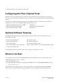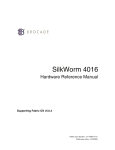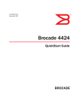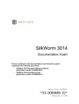
1
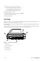
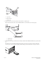
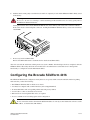
SilkWorm 4016
Quickstart Guide
Supporting Fabric OS v5.0.4
Publication Number: 53-1000174-01
*53-100051-01*
Publication Date: 1/30/2006
Copyright © 2005, Brocade Communications Systems, Incorporated.
ALL RIGHTS RESERVED.
Publication Number: 53-1000174-01
Brocade, the Brocade B weave logo, Secure Fabric OS, and SilkWorm are registered trademarks of Brocade Communications Systems,
Inc., in the United States and/or in other countries. All other brands, products, or service names are or may be trademarks or service
marks of, and are used to identify, products or services of their respective owners.
Notice: The information in this document is provided “AS IS,” without warranty of any kind, including, without limitation, any implied
warranty of merchantability, noninfringement or fitness for a particular purpose. Disclosure of information in this material in no way
grants a recipient any rights under Brocade's patents, copyrights, trade secrets or other intellectual property rights. Brocade reserves the
right to make changes to this document at any time, without notice, and assumes no responsibility for its use.
The authors and Brocade Communications Systems, Inc. shall have no liability or responsibility to any person or entity with respect to
any loss, cost, liability, or damages arising from the information contained in this book or the computer programs that accompany it.
Notice: The product described by this document may contain “open source” software covered by the GNU General Public License or
other open source license agreements. To find out which open source software is included in Brocade products, view the licensing terms
applicable to the open source software, and obtain a copy of the programming source code, please visit http://www.brocade.com/
support/oscd.
Export of technical data contained in this document may require an export license from the United States Government.
Brocade Communications Systems, Incorporated
Corporate Headquarters
Brocade Communications Systems, Inc.
1745 Technology Drive
San Jose, CA 95110
Tel: 1-408-333-8000
Fax: 1-408-333-8101
Email: [email protected]
Asia-Pacific Headquarters
Brocade Communications Singapore Pte. Ltd.
9 Raffles Place
#59-02 Republic Plaza 1
Singapore 048619
Tel: +65-6538-4700
Fax: +65-6538-0302
Email: [email protected]
European and Latin American Headquarters
Brocade Communications Switzerland Sàrl
Centre Swissair
Tour A - 2ème étage
29, Route de l'Aéroport
Case Postale 105
CH-1215 Genève 15
Switzerland
Tel: +41 22 799 56 40
Fax: +41 22 799 56 41
Email: [email protected]
Document History
The table below lists all published versions of the SilkWorm 4016 QuickStart Guide.
Document Title
Publication Number Summary of Changes
Publication Date
SilkWorm 4016 Quickstart Guide
53-1000174-01
January 2006
2 of 10
First release.
SilkWorm 4016 Quickstart Guide
53-1000174-01
Before You Begin
This document describes how to insert the Brocade SilkWorm 4016 switch into a blade server chassis and perform basic
initial configuration. It provides the following information:
•
•
•
•
•
•
•
•
•
“SilkWorm 4016 Features,” next
“Port Side” on page 4
“Unpacking the SilkWorm 4016” on page 5
“Inserting the SilkWorm 4016 into a Blade Server” on page 5
“Configuring the Brocade SilkWorm 4016” on page 7
“Backing Up the Configuration” on page 9
“Configuring the Fibre Channel Ports” on page 10
“Optional Software Features” on page 10
“Where to Go Next” on page 10
To ensure proper installation of the SilkWorm 4016, read this entire document before beginning.
SilkWorm 4016 Features
The SilkWorm 4016 provides the following features:
• Up to six external autosensing (1, 2, and 4 Gbit/sec) Fibre Channel ports:
- Universal and self-configuring: capable of becoming an F_Port (fabric enabled), FL_Port (fabric loop enabled),
or E_Port (expansion port)
-
Brocade ISL Trunking of external ports with trunking license
• Up to ten copper backplane F_ports with automatic negotiation to the highest common speed of all devices connected to
port, up to 4 Gbit/sec
• Frame filtering that augments the hardware zoning capabilities of the Brocade ASIC, which implements hardware
zoning at the port level of the switch
•
•
•
•
•
•
Brocade ASIC expanded capabilities, including World Wide Name (WWN) and device-level zoning
Hardware zoning, implemented by means of a firmware-accessible table per output port
Extensive diagnostics and monitoring capabilities
Unicast and broadcast data traffic support
Four SWL small form-factor pluggable (SFP) optical transceivers
One console port through the backplane connectors to the blade server chassis; refer to the blade server manufacturer’s
documentation for details about the connection
• One 10/100 Mbit/sec autosensing Ethernet port with an RJ-45 connector with manual override for speed, and full/half
duplex operation
• Light-emitting diodes (LEDs) for each external port:
-
One green/amber LED to indicate status for each port
One green/amber LED to indicate link speed for each port
SilkWorm 4016 Quickstart Guide
53-1000174-01
3 of 10
• The following system light-emitting diodes (LEDs):
- One green power LED to indicate system power-on
- One green/amber LED to indicate system status
- One green LED to indicate DRAC/MC status
Each SilkWorm 4016 switch contains:
• One PowerPC 405GP processor with a clock speed of 200 MHz
• One real-time clock with 10-year battery
• Five digital thermometers
Port Side
Externally accessible ports (ports 10 through 15) and all LEDs are on the port side of the switch. The port side faces out
when the switch is inserted into a PowerEdge 1855, as shown.
A complete description of the locations and interpretations of these LEDs can be found in the SilkWorm 4016 Hardware
Reference Manual.
The insertion and removal arm is located just above the port side of the SilkWorm 4016. The plastic insertion arm latch,
accessible at the front of the port side of the switch, is used to remove and insert the unit.
3
4
2
10
11
12
13
14
15
!
1
5
Figure 1
SilkWorm 4016 Port Side
1
Ethernet port
2
Power and status LEDs
3
Top of switch
4
Insertion arm latch
5
Autosensing ports
4 of 10
SilkWorm 4016 Quickstart Guide
53-1000174-01
The nonport (system) LEDs show switch-level information.
1
10
2
!
3
1
blade server chassis blade controller status
2
Switch status
3
Power and system status
Unpacking the SilkWorm 4016
To remove the SilkWorm 4016 from its shipping package:
1.
Open the shipping box and inspect the contents for damage.
Do not install a damaged unit: if the unit is damaged, contact your sales representative.
2.
Remove the cardboard accessory tray that sits on top of the SilkWorm 4016.
3.
Remove the switch from the box.
The protective foam ends will slide out with the switch.
4.
Remove the foam ends from the switch.
5.
Slide the SilkWorm 4016 out of the antistatic sleeve.
Inserting the SilkWorm 4016 into a Blade Server
To insert the SilkWorm 4016 into a blade server chassis:
1.
Unpack the SilkWorm 4016 from its shipping box as described earlier.
2.
Verify that the chassis I/O bay into which the SilkWorm 4016 is being inserted is empty. If necessary, install the SFP
modules according to the manufacturer’s documentation.
3.
Gripping from the top (1) and bottom (2) of the release latch, gently squeeze the latch to free the insertion arm.
Caution
The SilkWorm 4016 is designed to work in a specific I/O bay: usually either chassis I/O bay 3 or chassis I/O
bay 4 only. Do not insert the SilkWorm 4016 into any unsupported I/O bay.
SilkWorm 4016 Quickstart Guide
53-1000174-01
5 of 10
3
1
R
10
11
2
4.
1
Top of latch
2
Bottom of latch
3
Insertion arm
Swing the insertion arm out (away from the chassis) until it is completely open.
This positions the insertion arm to allow the SilkWorm 4016 to seat in the blade server chassis properly.
84-0000123-01 Rev. X
||||| |||| |||||||| |||||||| |||||||| ||||
RP040000111
1
2
5.
1
Insertion arm
2
Release latch
With the port side facing you and the insertion arm fully extended, slide the SilkWorm 4016 into the open chassis I/O
bay.
The illustration shows the SilkWorm 4016 being inserted into the chassis in a horizontal orientation. Other blade
servers may use a vertical orientation requiring a different blade position. This illustration is strictly for reference.
NET 1
13
12
NET 3
11
13
N
FA
dul
mo
st
e mu
be
rep
lac
ed
hin
wit
s!
ute
2 min
PSU 1
12
11
10
!
NET 2
PSU 4
IOI
mo
dul
st
e mu
be
rep
lac
ed
hin
wit
OI
PSU 1
NET 4
IOI
N
FA
s!
ute
2 min
OI
PSU 2
13
12
11
10
A
!
scale: 1/8" = 1"
6 of 10
SilkWorm 4016 Quickstart Guide
53-1000174-01
6.
Push the insertion arm gently toward the chassis until it is completely closed and the SilkWorm 4016 is firmly seated
in the I/O bay.
Warning
Do not force the arm closed. Doing so could cause damage. If the switch does not close easily, gently remove
the SilkWorm 4016 and reinsert it.
N
W
W
:00
:00
10
:34
:1E
:05
:2
:70
9
Closing the insertion arm locks the SilkWorm 4016 into the chassis I/O bay and activates the connection with the
blade server chassis via the backplane connectors. Locking the SilkWorm 4016 into the bay activates the switch and
switch LEDs.
MA
C0
0
05
1E
34
7
02
9
800
0
0
1
RQ
040 718-0
1
000
133 Rev.B
scale: 3/8" = 1"
7.
If necessary, install an SFP module.
Refer to the SFP manufacturer’s documentation for details about SFP modules.
After it is activated, the switch runs self-diagnostic tests (such as POST). After the diagnostics have completed, cable the
SilkWorm 4016 as directed by the blade server manuractuer’s documentation. Use the blade server’s management
functionality to configure the switch’s Ethernet IP address.
Configuring the Brocade SilkWorm 4016
The SilkWorm 4016 must be configured correctly before it can operate within a network and fabric. Before beginning,
make sure that you have the following:
•
•
•
•
•
•
The SilkWorm 4016 installed in a blade server chassis
A workstation computer with a terminal emulator (such as HyperTerminal)
An unused IP address and corresponding subnet mask and gateway address
A serial cable to connect to the blade server chassis
SFP transceivers and compatible fibre cables, as required
Access to an FTP server for backing up the switch configuration
Caution
Do not connect the switch to the network until the IP address is correctly set. For instructions on how to set the
IP address, see Set the Switch IP Address.
SilkWorm 4016 Quickstart Guide
53-1000174-01
7 of 10
To configure the SilkWorm 4016:
1.
Create a serial connection to the managment feature of the blade server chassis. Refer to the blade server
documentation for details about setting up the terminal emulator to connect and log in.
2.
After POST is complete and the switch is in a healthy state, log in to the switch as admin:
3.
a.
At the command prompt, type connect switch-x where x is the bay that the Silkworm 4016 is occupying.
b.
Log in to the Silkworm 4016 switch as admin and enter the password.
By default, the IP address is configured to 10.77.77.77. Replace the default IP address and related information by
issuing the ipAddrSet command and entering the requested information at the prompts, as shown in the following
example:
switch:admin> ipaddrset
Ethernet IP Address [10.77.77.77]:10.32.53.47
Ethernet Subnetmask [255.0.0.0]:255.255.240.0
Fibre Channel IP Address [0.0.0.0]:
Fibre Channel Subnetmask [0.0.0.0]:
Gateway IP Address [0.0.0.0]:10.32.48.1
Set IP address now? [y = set now, n = next reboot]:y
IP address being changed...
Committing configuration...Done.
switch:admin>
Optionally, verify that the address was correctly set by typing the ipAddrShow command.
4.
Remove the plug from the Ethernet port and connect an Ethernet cable to the switch Ethernet port and to the
workstation or to an Ethernet network containing the workstation.
Note
At this point, the switch can be accessed remotely, by command line or by Web Tools. Ensure that the switch
is not being modified from any other connections during the remaining tasks.
5.
Log on to the switch by telnet, using the administrative account.
6.
Modify the domain ID if required.
The default domain ID is 1. If the switch is not powered on until after it is connected to the fabric and the default
domain ID is already in use, the domain ID for the new switch is automatically reset to a unique value. If the switch is
connected to the fabric after is has been powered on and the default domain ID is already in use, the fabric segments.
To find the domain IDs that are currently in use, run the fabricShow command on another switch in the fabric.
a.
On the SilkWorm 4016 that is being configured, disable the switch using the switchDisable command.
b.
Enter the configure command.
The command prompts display sequentially; enter a new value or press Enter to accept each default value. The
SilkWorm 4016 now has a unique domain ID and can join the fabric.
c.
Reenable the switch by entering the switchEnable command.
Note
It could take a short time (typically a few seconds but sometimes a little longer) for the
newly added switch to appear in the fabric display with its newly assigned domain ID.
8 of 10
SilkWorm 4016 Quickstart Guide
53-1000174-01
7.
Install the SFP transceivers as required.
a.
Remove the dust plugs from the ports to be used as well as any end caps from.
b.
Position a transceiver so that it is oriented correctly and insert it into a port until it is firmly seated and the
latching mechanism clicks.
For instructions specific to the type of transceiver, refer to the transceiver manufacturer's documentation.
c.
8.
Repeat steps a and b for the remaining ports, as required.
Connect the cables to the transceivers.
The transceivers are keyed to ensure correct orientation. If a transceiver does not install easily, ensure that it is
correctly oriented and that all of the end caps have been removed.
The cables used in trunking groups must meet specific requirements. For a list of these requirements, refer to the
Brocade Fabric OS Administrator’s Guide.
Caution
A 50-micron cable should not be bent to a radius less than 2 inches under full tensile load and 1.2 inches with
no tensile load.
9.
a.
Orient a cable connector so that the key (the ridge on one side of connector) aligns with the slot in the
transceiver. Then, insert the cable into the transceiver until the latching mechanism clicks. For instructions
specific to cable type, refer to the cable manufacturer's documentation.
b.
Repeat this procedure for the remaining transceivers.
Check the LEDs to verify that all components are functional. For information about LED patterns, refer to the
SilkWorm 4016 Hardware Reference Manual.
10. Verify the correct operation of the SilkWorm 4016 by typing the switchShow command from the workstation,
followed by the fabricShow command.
Backing Up the Configuration
Back up the switch configuration to an FTP server by typing the configUpload command and following the prompts.
This command uploads the switch configuration to the server, making it available for downloading to a replacement
switch if necessary. Brocade recommends backing up the configuration on a regular basis to ensure that a complete
configuration is available for downloading to a replacement switch.
For specific instructions about how to back up the configuration, refer to the Fabric OS Administrator’s Guide. The
switchShow, fabricShow, and configUpload commands are described in detail in the Fabric OS Command Reference
Manual.
Connecting to the Switch Using Web Tools
To connect to the switch using Brocade’s Web Tools:
1.
On the management console, open a Web browser, such as Internet Explorer.
The Web browser must be connected to the same network as the switch.
SilkWorm 4016 Quickstart Guide
53-1000174-01
9 of 10
2.
Enter the IP address of the switch in the address field.
Configuring the Fibre Channel Ports
The blade server chassis managment feature provides the control point for the chassis. Each blade server chassis has a
serial connection to each switch chassis I/O bay. These connections are used for configuring and monitoring the installed
switches.
For details about configuring the Fibre Channel ports on the SilkWorm 4016, refer to the blade server manufacturer’s
documentation. You can access the SilkWorm 4016 management interface via:
• Simple Network Management Protocol (SNMP)
• Management Information Base (MIB)
• telnet/command line interface (CLI)
• API interface
• Web Browser Management Interface
• Fabric Watch
Optional Software Features
The SilkWorm 4016 supports the following optional Brocade software, which is activated with the purchase of the
corresponding license key:
•
•
•
•
a.
Brocade Advanced Web Toolsa
Brocade Advanced
Zoninga
Brocade ISL Trunking
Brocade Advanced Performance Monitoring
•
•
•
•
Brocade Fabric Watch
Brocade Secure Fabric OS
Port on Demand (POD) licensing
Support for Brocade Fabric Access API and API Scripting Toolkit
included with the SilkWorm 4016
For detailed information on any of these features, refer to the Fabric OS Administrator’s Guide.
Where to Go Next
You can find more information about the SilkWorm 4016 switch module and other topics from the following sources:
• SilkWorm 4016 Hardware Reference Manual
• Fabric OS v5.0.4 Release Notes
• For additional Brocade documentation, visit the Brocade SAN Info Center and click the Resource Library location:
http://www.brocade.com
• For information on the supported features, refer to the documentation on the Brocade Documentation CD-ROM.
• Release notes are available on the Brocade Connect Web site and are also bundled with the Fabric OS firmware.
10 of 10
SilkWorm 4016 Quickstart Guide
53-1000174-01