1
PMOR3021S
PMOR3021B
PMOR3021R
DESCRIPTION AND FUNCTION OF COMPONENTS
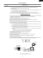
monitor switch contacts.
CAUTION: BEFORE REPLACING A BLOWN MONITOR
FUSE TEST THE STOP SWITCH, PRIMARY
INTERLOCK SWITCH, SECONDARY INTERLOCK SWITCH AND MONITOR SWITCH FOR
PROPER OPERATION. (REFER TO CHAPTER "TEST PROCEDURE").
NOTE: MONITOR FUSE AND SWITCH ARE REPLACED
AS AN ASSEMBLY
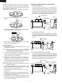
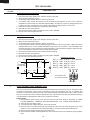
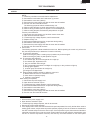
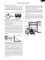
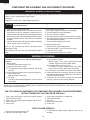
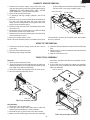
DOOR OPEN MECHANISM
The door is opened by pushing the open button on the
control panel, refer to the Figure D-1.
When the open button is pushed, the open button pushes up
the open lever, and then the open lever pushes up the latch
head. The latch heads are moved upward and released from
latch hook. Now the door will open.
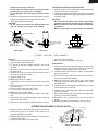
Latch heads
Latch hook
THERMAL CUT-OUT (HOOD )
Stop switch
This thermal cut-out located on the right base plate. It is
designed to automatically turn on the hood fan motor
whenever the hot air rising from the conventional range
below causes the temperature at the thermal cut-out to rise
o
o
to 140 F (60 C) or higher, thus removing this hot air from
around microwave oven. When the temperature around the
o
o
thermal cut-out drops to 113 F (45 C) or lower, the thermal
cut-out shuts off the hood fan motor.
Primary
interlock switch
Door
Monitor switch
Secondary
interlock switch
THERMAL CUT-OUT (OVEN )
Open lever
This thermal cut-out is located on the top of the oven cavity.
It is designed to prevent damage to the oven unit if the food
in the oven catches fire due to overheating produced by
improper setting of cooking time or failure of control unit.
Under normal operation, the thermal cut-out remains
o
closed. However, the thermal cut-out will open at 293 F
o
(145 C) causing the oven to shut down.
Figure D-1. Door Open Mechanism
STOP, PRIMARY INTERLOCK AND SECONDARY
INTERLOCK SWITCHES
The secondary interlock switch is mounted in the lower
position of the latch hook and the stop switch is mounted in
the upper position of the latch hook. The primary interlock
switch is also in the upper position of the latch hook. They
are activated by the latch heads on the door. When the door
is opened, the switches interrupt the circuit to all components. A cook cycle cannot take place until the door is firmly
closed thereby activating both interlock switches.
COOLING FAN MOTOR
The cooling fan motor drives a blade which draws external
cool air. This cool air is directed through the air vanes
surrounding the magnetron and cools the magnetron. This
air is channelled through the oven cavity to remove steam
and vapors given off from the heating foods. It is then
exhausted through the exhausting air vents at the oven
cavity.
MONITOR SWITCH
The monitor switch is activated (the contacts opened) by the
latch head on the door while the door is closed. The switch
is intended to render the oven inoperative by means of
blowing the monitor fuse when the contacts of the primary
interlock switch and secondary interlock switch fail to open
when the door is opened.
HOOD FAN MOTOR
The hood fan motor is a two-speed, single-phase, double
pole induction type, requiring a hood fan capacitor. It is
located outside the upper rear part of the oven cavity, is to
remove, from around the oven, hot air rising from the
conventional electric or gas range over which it is installed.
This air is then expelled either vertically or horizontally
through the customer supplied duct system, or discharged
back into the kitchen.
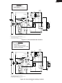
Functions:
1. When the door is opened, the monitor switch contact
close (to the ON condition) due to their being normally
closed. At this time the primary interlock switch and
secondary interlock switch are in the OFF condition
(contacts open) due to their being normally open contact
switches. And the contacts of relay (RY1) are in the ON
condition (contacts close).
2. As the door goes to a closed position, the monitor switch
contacts are first opened and the stop switch contacts
close, and then the primary interlock switch and the
secondary interlock switch contacts close. (On opening
the door, each of these switches operate inversely.)
3. If the door is opened, and the primary interlock switch
and secondary interlock switch contacts fail to open, the
monitor fuse blows simultaneously with closing of the
STIRRER MOTOR
The stirrer motors drive the stirrer fans to stir the microwave
radiation from the waveguide.
HOOD LAMP
The hood lamps are mounted at the hood lamp angle. The
hood lamps can be turned off and on by touching the Light
Options pad. And also the brightness can be varied to high
or low by touching the Light Options pad.
10