1
User’s Manual
HEIDENHAIN
Conversational Format
TNC 320
NC Software
340 551-02
English (en)
2/2007
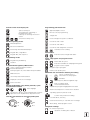
Controls on the visual display unit
Programming path movements
Split screen layout
Approach/depart contour
Switch between machining or
programming modes
Soft keys for selecting functions in
screen
Switch the soft-key rows
Machine operating modes
FK free contour programming
Straight line
Circle center/pole for polar coordinates
Circular arc with center
Manual Operation
Circular arc with radius
Electronic Handwheel
Circular arc with tangential connection
Positioning with Manual Data Input
Chamfer/corner rounding
Program Run, Single Block
Tool functions
Enter and call tool length and radius
Program Run, Full Sequence
Programming modes
Cycles, subprograms and program section
repeats
Programming and Editing
Define and call cycles
Test Run
Program/file management, TNC functions
Select or delete programs and files
External data transfer
Define program call, select datum and point tables
Enter and call labels for subprogramming and
program section repeats
Program stop in a program
Define touch probe cycles
Coordinate axes and numbers: Entering and editing
Select coordinate axes or
...
enter them into the program
MOD functions
Show help texts and illustrations
...
Display all current error messages
Numbers
Decimal point / Reverse algebraic sign
Pocket calculator
Moving the highlight, going directly to blocks, cycles
and parameter functions
Move highlight
Go directly to blocks, cycles and parameter functions.
Open the screen keyboard or a drop-down menu
Override control knobs for feed rate/spindle speed
100
100
Polar coordinate input/
Incremental dimensions
Q parameter programming/Q parameter status
Assume actual position or values from calculator
Skip dialog questions, delete words
Confirm entry and resume dialog
Conclude block, exit entry
Clear numerical entry or clear TNC error message
50
150
50
150
Abort dialog, delete program section
F %
0
S %
0
Navigation in dialogs
No function at present
Up/down one dialog box or button
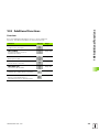
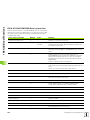
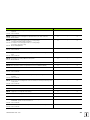
TNC Model, Software and Features
This manual describes functions and features provided by TNCs as of
the following NC software numbers.
TNC model
NC software number
TNC 320
340 551-xx
The machine tool builder adapts the usable features of the TNC to his
machine by setting machine parameters. Some of the functions
described in this manual may not be among the features provided by
the TNC on your machine tool.
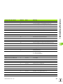
TNC functions that may not be available on your machine include:
Probing function for the 3-D touch probe
Rigid tapping
Returning to the contour after an interruption
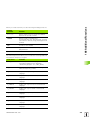
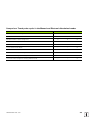
In addition, the TNC 320 also has software options that can be enabled
by your machine tool builder.
Software option
Additional axis for 4 axes and open-loop spindle
Additional axis for 5 axes and open-loop spindle
Cylinder surface interpolation (Cycles 27, 28 and 29)
Please contact your machine tool builder to become familiar with the
features of your machine.
Many machine manufacturers, as well as HEIDENHAIN, offer
programming courses for the TNCs. We recommend these courses as
an effective way of enhancing your TNC programming skill and sharing
information and ideas with other TNC users.
Intended Area of Application
The TNC complies with the limits for a Class A device in accordance
with the specifications in EN 55022, and is intended for use primarily
in industrially-zoned areas.
HEIDENHAIN TNC 320
5
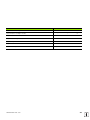
Contents
1
2
3
4
5
6
7
8
9
10
11
12
13
14
Introduction
Manual Operation and Setup
Positioning with Manual Data Input
Programming: Fundamentals of File
Management, Programming Aids
Programming: Tools
Programming: Programming Contours
Programming: Miscellaneous Functions
Programming: Cycles
Programming: Subprograms and
Program Section Repeats
Programming: Q Parameters
Test Run and Program Run
MOD Functions
Touch Probe Cycles
Technical Information
¢¬
7
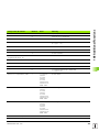
1 Introduction ..... 27
1.1 The TNC 320 ..... 28
Programming: HEIDENHAIN conversational format ..... 28
Compatibility ..... 28
1.2 Visual Display Unit and Operating Panel ..... 29
Visual display unit ..... 29
Screen layout ..... 29
Operating panel ..... 30
1.3 Operating Modes ..... 31
Manual operation and electronic handwheel ..... 31
Positioning with Manual Data Input ..... 31
Programming and Editing ..... 31
Test Run ..... 32
Program Run, Full Sequence and Program Run, Single Block ..... 32
1.4 Status Displays ..... 33
“General” status display ..... 33
Additional status displays ..... 34
1.5 Accessories: HEIDENHAIN 3-D Touch Probes and Electronic Handwheels ..... 37
3-D touch probes ..... 37
HR electronic handwheels ..... 37
HEIDENHAIN TNC 320
9
2 Manual Operation and Setup ..... 39
2.1 Switch-On, Switch-Off ..... 40
Switch-on ..... 40
Switch-off ..... 41
2.2 Moving the Machine Axes ..... 42
Note ..... 42
To traverse with the machine axis direction buttons: ..... 42
Incremental jog positioning ..... 43
Traversing with the HR 410 electronic handwheel ..... 44
2.3 Spindle Speed S, Feed Rate F and Miscellaneous Functions M ..... 45
Function ..... 45
Entering values ..... 45
Changing the spindle speed and feed rate ..... 46
2.4 Datum Setting (Without a 3-D Touch Probe) ..... 47
Note ..... 47
Preparation ..... 47
Datum setting with axis keys ..... 47
10
3 Positioning with Manual Data Input (MDI) ..... 49
3.1 Programming and Executing Simple Machining Operations ..... 50
Positioning with Manual Data Input (MDI) ..... 50
Protecting and erasing programs in $MDI ..... 52
HEIDENHAIN TNC 320
11
4 Programming: Fundamentals of NC, File Management, Programming Aids ..... 53
4.1 Fundamentals ..... 54
Position encoders and reference marks ..... 54
Reference system ..... 54
Reference system on milling machines ..... 55
Polar coordinates ..... 56
Absolute and incremental workpiece positions ..... 57
Setting the datum ..... 58
4.2 File Management: Fundamentals ..... 59
Files ..... 59
Screen keypad ..... 60
Data backup ..... 60
4.3 Working with the File Manager ..... 61
Directories ..... 61
Paths ..... 61
Overview: Functions of the file manager ..... 62
Calling the file manager ..... 63
Selecting drives, directories and files ..... 64
Creating a new directory ..... 65
Copying a single file ..... 66
Copying a directory ..... 66
Choosing one of the last 10 files selected ..... 67
Deleting a file ..... 67
Deleting a directory ..... 67
Marking files ..... 68
Renaming a file ..... 69
File sorting ..... 69
Additional functions ..... 69
Data transfer to or from an external data medium ..... 70
Copying files into another directory ..... 72
The TNC in a network ..... 73
USB devices on the TNC ..... 74
4.4 Creating and Writing Programs ..... 75
Organization of an NC program in HEIDENHAIN conversational format ..... 75
Define the blank: BLK FORM ..... 75
Creating a new part program ..... 76
Programming tool movements in conversational format ..... 78
Actual position capture ..... 79
Editing a program ..... 80
The TNC search function ..... 83
12
4.5 Interactive Programming Graphics ..... 85
Generating / Not generating graphics during programming: ..... 85
Generating a graphic for an existing program ..... 85
Block number display ON/OFF ..... 86
Erasing the graphic ..... 86
Magnifying or reducing a detail ..... 86
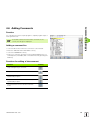
4.6 Adding Comments ..... 87
Function ..... 87
Adding a comment line ..... 87
Functions for editing of the comment ..... 87
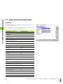
4.7 Integrated Pocket Calculator ..... 88
Operation ..... 88
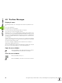
4.8 The Error Messages ..... 90
Display of errors ..... 90
Open the error window ..... 90
Close the error window ..... 90
Detailed error messages ..... 91
INTERNAL INFO soft key ..... 91
Deleting errors ..... 91
Error log ..... 92
Keystroke log ..... 92
Informational texts ..... 93
Saving service files ..... 93
HEIDENHAIN TNC 320
13
5 Programming: Tools ..... 95
5.1 Entering Tool-Related Data ..... 96
Feed rate F ..... 96
Spindle speed S ..... 97
5.2 Tool Data ..... 98
Requirements for tool compensation ..... 98
Tool numbers and tool names ..... 98
Tool length L ..... 98
Tool radius R ..... 98
Delta values for lengths and radii ..... 99
Entering tool data into the program ..... 99
Entering tool data in the table ..... 100
Pocket table for tool changer ..... 104
Calling tool data ..... 107
Tool change ..... 108
5.3 Tool Compensation ..... 110
Introduction ..... 110
Tool length compensation ..... 110
Tool radius compensation ..... 111
14
6 Programming: Programming Contours ..... 115
6.1 Tool Movements ..... 116
Path functions ..... 116
FK Free Contour Programming ..... 116
Miscellaneous functions M ..... 116
Subprograms and program section repeats ..... 116
Programming with Q parameters ..... 116
6.2 Fundamentals of Path Functions ..... 117
Programming tool movements for workpiece machining ..... 117
6.3 Contour Approach and Departure ..... 121
Overview: Types of paths for contour approach and departure ..... 121
Important positions for approach and departure ..... 121
Approaching on a straight line with tangential connection: APPR LT ..... 123
Approaching on a straight line perpendicular to the first contour point: APPR LN ..... 123
Approaching on a circular path with tangential connection: APPR CT ..... 124
Approaching on a circular arc with tangential connection from a straight line to the contour: APPR LCT ..... 125
Departing on a straight line with tangential connection: DEP LT ..... 125
Departing on a straight line perpendicular to the last contour point: DEP LN ..... 126
Departure on a circular path with tangential connection: DEP CT ..... 126
Departing on a circular arc tangentially connecting the contour and a straight line: DEP LCT ..... 127
6.4 Path Contours—Cartesian Coordinates ..... 128
Overview of path functions ..... 128
Straight Line L ..... 128
Inserting a chamfer CHF between two straight lines ..... 129
Corner rounding RND ..... 130
Circle center CC ..... 131
Circular path C around circle center CC ..... 132
Circular path CR with defined radius ..... 132
Circular path CT with tangential connection ..... 134
6.5 Path Contours—Polar Coordinates ..... 139
Overview ..... 139
Polar coordinate origin: Pole CC ..... 139
Straight line LP ..... 140
Circular path CP around pole CC ..... 140
Circular path CTP with tangential connection ..... 141
Helical interpolation ..... 141
HEIDENHAIN TNC 320
15
6.6 Path Contours—FK Free Contour Programming ..... 146
Fundamentals ..... 146
Graphics during FK programming ..... 147
Initiating the FK dialog ..... 149
Pole for FK programming ..... 149
Free programming of straight lines ..... 150
Free programming of circular arcs ..... 150
Input possibilities ..... 151
Auxiliary points ..... 154
Relative data ..... 155
16
7 Programming: Miscellaneous Functions ..... 163
7.1 Entering Miscellaneous Functions M and STOP ..... 164
Fundamentals ..... 164
7.2 Miscellaneous Functions for Program Run Control, Spindle and Coolant ..... 166
Overview ..... 166
7.3 Programming Machine-Referenced Coordinates: M91/M92 ..... 167
Programming machine-referenced coordinates: M91/M92 ..... 167
7.4 Miscellaneous Functions for Contouring Behavior ..... 169
Machining small contour steps: M97 ..... 169
Machining open contours: M98 ..... 171
Feed rate for circular arcs: M109/M110/M111 ..... 171
Calculating the radius-compensated path in advance (LOOK AHEAD): M120 ..... 172
Superimposing handwheel positioning during program run: M118 ..... 173
Retraction from the contour in the tool-axis direction: M140 ..... 174
Suppressing touch probe monitoring: M141 ..... 175
Delete basic rotation: M143 ..... 175
Automatically retract tool from the contour at an NC stop: M148 ..... 176
7.5 Miscellaneous Functions for Rotary Axes ..... 177
Feed rate in mm/min on rotary axes A, B, C: M116 ..... 177
Shorter-path traverse of rotary axes: M126 ..... 178
Reducing display of a rotary axis to a value less than 360°: M94 ..... 179
HEIDENHAIN TNC 320
17
8 Programming: Cycles ..... 181
8.1 Working with Cycles ..... 182
Machine-specific cycles ..... 182
Defining a cycle using soft keys ..... 183
Defining a cycle using the GOTO function ..... 183
Calling cycles ..... 185
8.2 Cycles for Drilling, Tapping and Thread Milling ..... 186
Overview ..... 186
DRILLING (Cycle 200) ..... 188
REAMING (Cycle 201) ..... 190
BORING (Cycle 202) ..... 192
UNIVERSAL DRILLING (Cycle 203) ..... 194
BACK BORING (Cycle 204) ..... 196
UNIVERSAL PECKING (Cycle 205) ..... 198
BORE MILLING (Cycle 208) ..... 201
TAPPING NEW with floating tap holder (Cycle 206) ..... 203
RIGID TAPPING without a floating tap holder NEW (Cycle 207) ..... 205
TAPPING WITH CHIP BREAKING (Cycle 209) ..... 207
Fundamentals of thread milling ..... 209
THREAD MILLING (Cycle 262) ..... 211
THREAD MILLING/COUNTERSINKING (Cycle 263) ..... 213
THREAD DRILLING/MILLING (Cycle 264) ..... 217
HELICAL THREAD DRILLING/MILLING (Cycle 265) ..... 221
OUTSIDE THREAD MILLING (Cycle 267) ..... 225
8.3 Cycles for Milling Pockets, Studs and Slots ..... 231
Overview ..... 231
POCKET MILLING (Cycle 4) ..... 232
POCKET FINISHING (Cycle 212) ..... 234
STUD FINISHING (Cycle 213) ..... 236
CIRCULAR POCKET (Cycle 5) ..... 238
CIRCULAR POCKET FINISHING (Cycle 214) ..... 240
CIRCULAR STUD FINISHING (Cycle 215) ..... 242
SLOT (oblong hole) with reciprocating plunge-cut (Cycle 210) ..... 244
CIRCULAR SLOT (oblong hole) with reciprocating plunge-cut (Cycle 211) ..... 247
8.4 Cycles for Machining Point Patterns ..... 253
Overview ..... 253
CIRCULAR PATTERN (Cycle 220) ..... 254
LINEAR PATTERN (Cycle 221) ..... 256
18
8.5 SL Cycles ..... 260
Fundamentals ..... 260
Overview of SL cycles ..... 262
CONTOUR GEOMETRY (Cycle 14) ..... 263
Overlapping contours ..... 264
CONTOUR DATA (Cycle 20) ..... 267
PILOT DRILLING (Cycle 21) ..... 268
ROUGH OUT (Cycle 22) ..... 269
FLOOR FINISHING (Cycle 23) ..... 270
SIDE FINISHING (Cycle 24) ..... 271
CONTOUR TRAIN (Cycle 25) ..... 272
CYLINDER SURFACE (Cycle 27, software option 1) ..... 274
CYLINDER SURFACE slot milling (Cycle 28, software option 1) ..... 276
CYLINDER SURFACE ridge milling (Cycle 29, software option 1) ..... 278
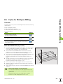
8.6 Cycles for Multipass Milling ..... 289
Overview ..... 289
MULTIPASS MILLING (Cycle 230) ..... 289
RULED SURFACE (Cycle 231) ..... 291
FACE MILLING (Cycle 232) ..... 294
8.7 Coordinate Transformation Cycles ..... 302
Overview ..... 302
Effect of coordinate transformations ..... 302
DATUM SHIFT (Cycle 7) ..... 303
DATUM SHIFT with datum tables (Cycle 7) ..... 304
MIRROR IMAGE (Cycle 8) ..... 307
ROTATION (Cycle 10) ..... 309
SCALING FACTOR (Cycle 11) ..... 310
AXIS-SPECIFIC SCALING (Cycle 26) ..... 311
8.8 Special Cycles ..... 314
DWELL TIME (Cycle 9) ..... 314
PROGRAM CALL (Cycle 12) ..... 315
ORIENTED SPINDLE STOP (Cycle 13) ..... 316
HEIDENHAIN TNC 320
19
9 Programming: Subprograms and Program Section Repeats ..... 317
9.1 Labeling Subprograms and Program Section Repeats ..... 318
Labels ..... 318
9.2 Subprograms ..... 319
Operating sequence ..... 319
Programming notes ..... 319
Programming a subprogram ..... 319
Calling a subprogram ..... 319
9.3 Program Section Repeats ..... 320
Label LBL ..... 320
Operating sequence ..... 320
Programming notes ..... 320
Programming a program section repeat ..... 320
Calling a program section repeat ..... 320
9.4 Separate Program as Subprogram ..... 321
Operating sequence ..... 321
Programming notes ..... 321
Calling any program as a subprogram ..... 322
9.5 Nesting ..... 323
Types of nesting ..... 323
Nesting depth ..... 323
Subprogram within a subprogram ..... 323
Repeating program section repeats ..... 324
Repeating a subprogram ..... 325
9.6 Programming Examples ..... 326
20
10 Programming: Q Parameters ..... 333
10.1 Principle and Overview ..... 334
Programming notes ..... 335
Calling Q parameter functions ..... 335
10.2 Part Families—Q Parameters in Place of Numerical Values ..... 336
Example NC blocks ..... 336
Example ..... 336
10.3 Describing Contours through Mathematical Operations ..... 337
Function ..... 337
Overview ..... 337
Programming fundamental operations ..... 338
10.4 Trigonometric Functions ..... 339
Definitions ..... 339
Programming trigonometric functions ..... 340
10.5 Calculating Circles ..... 341
Function ..... 341
10.6 If-Then Decisions with Q Parameters ..... 342
Function ..... 342
Unconditional jumps ..... 342
Programming If-Then decisions ..... 342
Abbreviations used: ..... 343
10.7 Checking and Changing Q Parameters ..... 344
Procedure ..... 344
10.8 Additional Functions ..... 345
Overview ..... 345
FN14: ERROR: Displaying error messages ..... 346
FN16: F-PRINT: Formatted output of texts or Q parameter values ..... 348
FN18: SYS-DATUM READ Read system data ..... 352
FN19: PLC: Transferring values to the PLC ..... 360
FN20: WAIT FOR: NC and PLC synchronization ..... 361
FN29: PLC: Transferring values to the PLC ..... 363
FN37:EXPORT ..... 364
10.9 Accessing Tables with SQL Commands ..... 365
Introduction ..... 365
A Transaction ..... 366
Programming SQL commands ..... 368
Overview of the soft keys ..... 368
SQL BIND ..... 369
SQL SELECT ..... 370
SQL FETCH ..... 373
SQL UPDATE ..... 374
SQL INSERT ..... 374
SQL COMMIT ..... 375
SQL ROLLBACK ..... 375
HEIDENHAIN TNC 320
21
10.10 Entering Formulas Directly ..... 376
Entering formulas ..... 376
Rules for formulas ..... 378
Programming example ..... 379
10.11 String Parameters ..... 380
String processing functions ..... 380
Assigning string parameters ..... 381
Chain-linking string parameters ..... 381
Converting a numerical value to a string parameter ..... 382
Copying a substring from a string parameter ..... 383
Converting a string parameter to a numerical value ..... 384
Checking a string parameter ..... 385
Finding the length of a string parameter ..... 386
Reading the alphabetic order ..... 387
10.12 Preassigned Q Parameters ..... 388
Values from the PLC: Q100 to Q107 ..... 388
Active tool radius: Q108 ..... 388
Tool axis: Q109 ..... 388
Spindle status: Q110 ..... 389
Coolant supply: Q111 ..... 389
Overlap factor: Q112 ..... 389
Unit of measurement for dimensions in the program: Q113 ..... 389
Tool length: Q114 ..... 389
Coordinates after probing during program run ..... 390
10.13 Example Program ..... 391
22
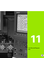
11 Test Run and Program Run ..... 399
11.1 Graphics ..... 400
Function ..... 400
Overview of display modes ..... 401
Plan view ..... 401
Projection in 3 planes ..... 402
3-D view ..... 403
Magnifying details ..... 404
Repeating graphic simulation ..... 405
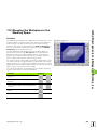
Measuring the machining time ..... 406
11.2 Showing the Workpiece in the Working Space ..... 407
Function ..... 407
11.3 Functions for Program Display ..... 408
Overview ..... 408
11.4 Test Run ..... 409
Function ..... 409
11.5 Program Run ..... 411
Function ..... 411
Run a part program ..... 411
Interrupting machining ..... 412
Moving the machine axes during an interruption ..... 412
Resuming program run after an interruption ..... 413
Mid-program startup (block scan) ..... 414
Returning-to-contour function active ..... 415
11.6 Automatic Program Start ..... 416
Function ..... 416
11.7 Optional Block Skip ..... 417
Function ..... 417
Inserting the “/” character ..... 417
Erasing the “/” character ..... 417
11.8 Optional Program-Run Interruption ..... 418
Function ..... 418
HEIDENHAIN TNC 320
23
12 MOD Functions ..... 419
12.1 MOD Functions ..... 420
Selecting the MOD functions ..... 420
Changing the settings ..... 420
Exiting the MOD functions ..... 420
Overview of MOD functions ..... 421
12.2 Software Numbers ..... 422
Function ..... 422
12.3 Position Display Types ..... 423
Function ..... 423
12.4 Unit of Measurement ..... 424
Function ..... 424
12.5 Display Operating Times ..... 425
Function ..... 425
12.6 Entering Code Numbers ..... 426
Function ..... 426
12.7 Setting the Data Interfaces ..... 427
Serial interface on the TNC 320 ..... 427
Function ..... 427
Setting the RS-232 interface ..... 427
Setting the baud rate (baudRate) ..... 427
Set the protocol (protocol) ..... 427
Set the data bits (dataBits) ..... 428
Parity check (parity) ..... 428
Setting the stop bits (stopBits) ..... 428
Setting the handshake (flowControl) ..... 428
Setting the operating mode of the external device (fileSystem) ..... 429
Software for data transfer ..... 430
12.8 Ethernet Interface ..... 432
Introduction ..... 432
Connection possibilities ..... 432
Connecting the control to the network ..... 433
24
13 Touch Probe Cycles in the Manual and Electronic Handwheel Modes ..... 439
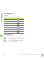
13.1 Introduction ..... 440
Overview ..... 440
Selecting probe cycles ..... 440
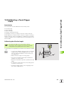
13.2 Calibrating a Touch Trigger Probe ..... 441
Introduction ..... 441
Calibrating the effective length ..... 441
Calibrating the effective radius and compensating center misalignment ..... 442
Displaying calibration values ..... 443
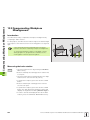
13.3 Compensating Workpiece Misalignment ..... 444
Introduction ..... 444
Measuring the basic rotation ..... 444
Displaying a basic rotation ..... 445
To cancel a basic rotation ..... 445
13.4 Setting the Datum with a 3-D Touch Probe ..... 446
Introduction ..... 446
To set the datum in any axis (see figure at right) ..... 446
Corner as datum—using points already probed for a basic rotation (see figure at right) ..... 447
Circle center as datum ..... 448
13.5 Measuring Workpieces with a 3-D Touch Probe ..... 449
Introduction ..... 449
To find the coordinate of a position on an aligned workpiece ..... 449
Finding the coordinates of a corner in the working plane ..... 449
To measure workpiece dimensions ..... 450
To find the angle between the angle reference axis and a side of the workpiece ..... 451
13.6 Touch Probe Data Management ..... 452
Introduction ..... 452
Touch-probe table: Touch-probe data ..... 452
Editing tool-probe tables ..... 453
13.7 Automatic Workpiece Measurement ..... 454
Overview ..... 454
Reference system for measurement results ..... 454
DATUM PLANE (touch probe cycle 0) ..... 455
DATUM PLANE (touch probe cycle 1) ..... 457
MEASURING (touch probe cycle 3) ..... 458
HEIDENHAIN TNC 320
25
14 Tables and Overviews ..... 459
14.1 Machine-Specific User Parameters ..... 460
Function ..... 460
14.2 Pin Layout and Connecting Cable for the Data Interfaces ..... 464
RS-232-C/V.24 interface for HEIDENHAIN devices ..... 464
Non-HEIDENHAIN devices ..... 465
Ethernet interface RJ45 socket ..... 465
14.3 Technical Information ..... 466
14.4 Exchanging the Buffer Battery ..... 471
26
1
Introduction
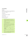
1.1 The TNC 320
1.1 The TNC 320
HEIDENHAIN TNC controls are workshop-oriented contouring
controls that enable you to program conventional machining
operations right at the machine in an easy-to-use conversational
programming language. The TNC 320 is designed for milling and
drilling machine tools with up to 4 axes (optionally 5 axes). Instead of
the fourth or fifth axis, you can also change the angular position of the
spindle under program control.
Keyboard and screen layout are clearly arranged in such a way that the
functions are fast and easy to use.
Programming: HEIDENHAIN conversational
format
HEIDENHAIN conversational programming is an especially easy
method of writing programs. Interactive graphics illustrate the
individual machining steps for programming the contour. If a
production drawing is not dimensioned for NC, the HEIDENHAIN FK
free contour programming does the necessary calculations
automatically. Workpiece machining can be graphically simulated
either during or before actual machining.
You can also enter and test one program while the control is running
another.
Compatibility
The scope of functions of the TNC 320 does not correspond to that of
the TNC 4xx and iTNC 530 series of controls. Therefore, machining
programs created on HEIDENHAIN contouring controls (starting from
the TNC 150 B) may not always run on the TNC 320. If NC blocks
contain invalid elements, the TNC will mark them during download as
ERROR blocks.
28
1 Introduction
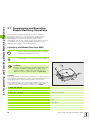
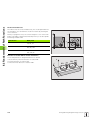
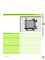
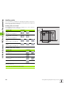
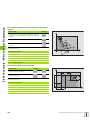
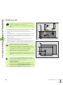
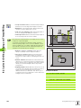
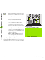
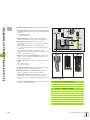
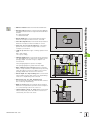
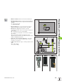
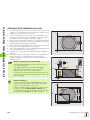
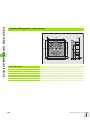
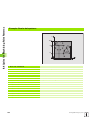
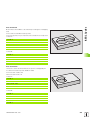
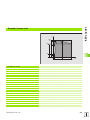
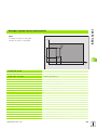
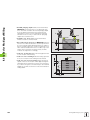
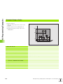
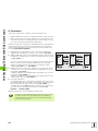
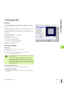
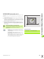
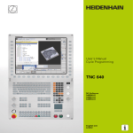
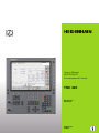
Visual display unit
The TNC is delivered with a 15-inch TFT color flat-panel display (see
figure at top right).
1
1
Header
2
When the TNC is on, the selected operating modes are shown in
the screen header: the machining mode at the left and the
programming mode at right. The currently active mode is
displayed in the larger box, where the dialog prompts and TNC
messages also appear (unless the TNC is showing only graphics).
Soft keys
3
4
5
6
7
8
8
In the footer the TNC indicates additional functions in a soft-key
row. You can select these functions by pressing the keys
immediately below them. The lines immediately above the softkey row indicate the number of soft-key rows that can be called
with the black arrow keys to the right and left. The active soft-key
row is indicated by brightened bar.
Soft-key selection keys
Switches the soft-key rows
Sets the screen layout
Shift key for switchover between machining and programming
modes
Soft-key selection keys for machine tool builders
Switches soft-key rows for machine tool builders
7
5
2
6
1
31
4
4
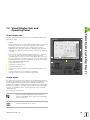
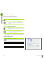
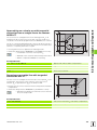
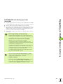
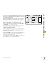
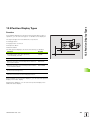
Screen layout
You select the screen layout yourself: In the programming mode of
operation, for example, you can have the TNC show program blocks in
the left window while the right window displays programming
graphics. You could also display status information in the right window
instead of the graphics, or display only program blocks in one large
window. The available screen windows depend on the selected
operating mode.
To change the screen layout:
Press the SPLIT SCREEN key: The soft-key row
shows the available layout options (see “Operating
Modes,” page 31).
Select the desired screen layout.
HEIDENHAIN TNC 320
29
1.2 Visual Display Unit and Operating Panel
1.2 Visual Display Unit and
Operating Panel
1.2 Visual Display Unit and Operating Panel
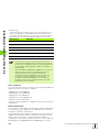
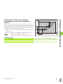
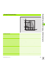
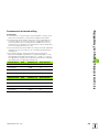
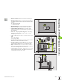
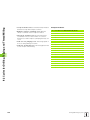
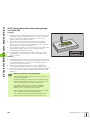
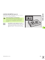
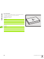
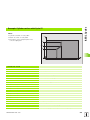
Operating panel
The TNC 320 is delivered with an integrated keyboard. The figure at
right shows the controls and displays of the keyboard:
1
2
3
4
5
6
7
File management
Online calculator
MOD function
HELP function
Programming modes
Machine operating modes
Initiation of programming dialog
Arrow keys and GOTO jump command
Numerical input and axis selection
Navigation keys
The functions of the individual keys are described on the inside front
cover.
1
4
1
Machine panel buttons, e.g. NC START or NC STOP, are
described in the manual for your machine tool.
6
3
2
1
7
30
5
1 Introduction
1.3 Operating Modes
1.3 Operating Modes
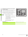
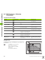
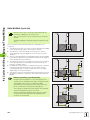
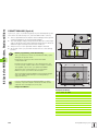
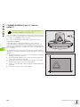
Manual operation and electronic handwheel
The Manual Operation mode is required for setting up the machine
tool. In this operating mode, you can position the machine axes
manually or by increments and set the datums.
The Electronic Handwheel mode of operation allows you to move the
machine axes manually with the HR electronic handwheel.
Soft keys for selecting the screen layout (select as described
previously)
Windows
Soft key
Positions
Left: positions—Right: status display
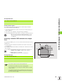
Positioning with Manual Data Input
This mode of operation is used for programming simple traversing
movements, such as for face milling or pre-positioning.
Soft keys for selecting the screen layout
Windows
Soft key
Program
Left: program blocks—Right: status display
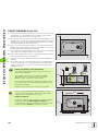
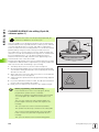
Programming and Editing
In this mode of operation you can write your part programs. The FK
free programming feature, the various cycles and the Q parameter
functions help you with programming and add necessary information.
If desired, you can have the programming graphics show the individual
steps.
Soft keys for selecting the screen layout
Windows
Soft key
Program
Left: program, right: programming graphics
HEIDENHAIN TNC 320
31
1.3 Operating Modes
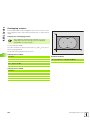
Test Run
In the Test Run mode of operation, the TNC checks programs and
program sections for errors, such as geometrical incompatibilities,
missing or incorrect data within the program or violations of the work
space. This simulation is supported graphically in different display
modes.
Soft keys for selecting the screen layout: see “Program Run, Full
Sequence and Program Run, Single Block,” page 32.
Program Run, Full Sequence and Program Run,
Single Block
In the Program Run, Full Sequence mode of operation the TNC
executes a part program continuously to its end or to a manual or
programmed stop. You can resume program run after an interruption.
In the Program Run, Single Block mode of operation you execute each
block separately by pressing the machine START button.
Soft keys for selecting the screen layout
Windows
Soft key
Program
Left: program, right: status
Left: program, right: graphics
graphics
32
1 Introduction
1.4 Status Displays
1.4 Status Displays
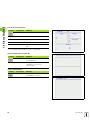
“General” status display
The status display 1 informs you of the current state of the machine
tool. It is displayed automatically in the following modes of operation:
Program Run, Single Block and Program Run, Full Sequence, except
if the screen layout is set to display graphics only, and
Positioning with Manual Data Input (MDI).
In the Manual mode and Electronic Handwheel mode the status
display appears in the large window.
Information in the status display
Symbol
Meaning
ACTL.
Actual or nominal coordinates of the current position.
XYZ
Machine axes; the TNC displays auxiliary axes in
lower-case letters. The sequence and quantity of
displayed axes is determined by the machine tool
builder. Refer to your machine manual for more
information.
11
Tool number T.
FSM
The displayed feed rate in inches corresponds to one
tenth of the effective value. Spindle speed S, feed
rate F and active M functions.
Axis locked.
Override setting in percent
Axis can be moved with the handwheel.
Axes are moving under a basic rotation.
No active program.
Program run started.
Program run stopped.
Program run is being aborted.
HEIDENHAIN TNC 320
33
1.4 Status Displays
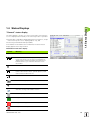
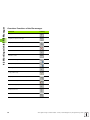
Additional status displays
The additional status displays contain detailed information on the
program run. They can be called in all operating modes except for the
Programming and Editing mode of operation.
To switch on the additional status display:
Call the soft-key row for screen layout.
Select the layout option for the additional status
display.
To select an additional status display:
Shift the soft-key rows until the STATUS soft keys
appear.
Select the desired additional status display, e.g.
general program information.
You can choose between several additional status displays with the
following soft keys:
General program information
Soft key
Assignment
Meaning
1
Name of the active main program
2
Active programs
3
Active machining cycle
4
Circle center CC (pole)
5
Machining time
6
Dwell time counter
1
2
3
4
5
6
34
1 Introduction
1.4 Status Displays
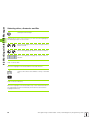
Positions and coordinates
Soft key
Assignment
Meaning
1
Type of position display, e.g. actual
position
2
Position display
3
Number of the active datum from the
preset table (function not available on
TNC 320).
3
Angle of a basic rotation
4
4
1
2
Information on tools
Soft key
Assignment
Meaning
1
T: Tool number and name
1
2
Tool axis
3
Tool lengths and radii
4
Oversizes (delta values) from TOOL
CALL (PGM) and the tool table (TAB)
4
5
Tool life, maximum tool life (TIME 1)
and maximum tool life for TOOL
CALL (TIME 2)
5
Display of the active tool and the
(next) replacement tool
6
6
HEIDENHAIN TNC 320
2
3
35
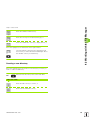
1.4 Status Displays
Coordinate transformations
Soft key
Assignment
Meaning
1
Program name
2
Active datum shift (Cycle 7)
3
Mirrored axes (Cycle 8)
4
Active rotation angle (Cycle 10)
5
Active scaling factor(s) (Cycles 11 /
26)
1
2
4
3
5
See “Coordinate Transformation Cycles” on page 302.
Active miscellaneous functions M
Soft key
Assignment
Meaning
1
List of the active M functions with
fixed meaning
2
List of the active M functions that are
adapted by your machine
manufacturer
1
2
Status of Q parameters
Soft key
Assignment
Meaning
1
List of Q parameters defined with the
Q PARAM LIST soft key
1
36
1 Introduction
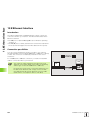
1.5 Accessories: HEIDENHAIN 3-D Touch Probes and Electronic Handwheels
1.5 Accessories: HEIDENHAIN
3-D Touch Probes and
Electronic Handwheels
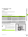
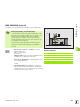
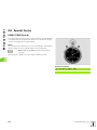
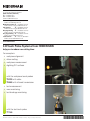
3-D touch probes
With the various HEIDENHAIN 3-D touch probe systems you can:
Automatically align workpieces
Quickly and precisely set datums
Measure the workpiece during program run
TS 220, TS 440 and TS 640 touch trigger probes
These touch probes are particularly effective for automatic workpiece
alignment, datum setting and workpiece measurement. The TS 220
transmits the triggering signals to the TNC via cable and may be a
more economical alternative.
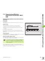
The TS 440 and TS 640 (see figures at right) feature infrared
transmission of the triggering signal to the TNC. This makes them
highly convenient for use on machines with automatic tool changers.
Principle of operation: HEIDENHAIN triggering touch probes feature a
wear resisting optical switch that generates an electrical signal as
soon as the stylus is deflected. This signal is transmitted to the TNC,
which stores the current position of the stylus as an actual value.
HR electronic handwheels
Electronic handwheels facilitate moving the axis slides precisely by
hand. A wide range of traverses per handwheel revolution is available.
Apart from the HR 130 and HR 150 integral handwheels,
HEIDENHAIN also offers the HR 410 portable handwheel.
HEIDENHAIN TNC 320
37
2
Manual Operation and
Setup
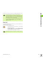
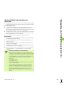
2.1 Switch-On, Switch-Off
2.1 Switch-On, Switch-Off
Switch-on
Switch-on and traversing the reference points can vary
depending on the machine tool. Refer to your machine
manual.
Switch on the power supply for control and machine. The TNC then
displays the following dialog:
SYSTEM STARTUP
TNC is started
POWER INTERRUPTED
TNC message that the power was interrupted—clear
the message.
CONVERT PLC PROGRAM
The PLC program of the TNC is automatically compiled.
RELAY EXT. DC VOLTAGE MISSING
Switch on external dc voltage. The TNC checks the
functioning of the EMERGENCY STOP circuit.
MANUAL OPERATION
TRAVERSE REFERENCE POINTS
Cross the reference points manually in the displayed
sequence: For each axis press the machine START
button, or
Cross the reference points in any sequence: Press
and hold the machine axis direction button for each
axis until the reference point has been traversed.
If your machine is equipped with absolute encoders, you
can leave out traversing the reference mark. In such a
case, the TNC is ready for operation immediately after the
machine control voltage is switched on.
40
2 Manual Operation and Setup
2.1 Switch-On, Switch-Off
The TNC is now ready for operation in the Manual Operation mode.
The reference points need only be traversed if the
machine axes are to be moved. If you intend only to write,
edit or test programs, you can select the Programming
and Editing or Test Run modes of operation immediately
after switching on the control voltage.
You can traverse the reference points later by pressing
the PASS OVER REFERENCE soft key in the Manual
Operation mode.
Switch-off
To prevent data being lost at switch-off, you need to shut down the
operating system as follows:
8
Select the Manual Operation mode.
8 Select the function for shutting down, confirm again
with the YES soft key.
8
When the TNC displays the message NOW IT IS SAFE
TO TURN POWER OFF in a superimposed window, you
may cut off the power supply to the TNC.
Inappropriate switch-off of the TNC can lead to data loss.
HEIDENHAIN TNC 320
41
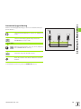
2.2 Moving the Machine Axes
2.2
Moving the Machine Axes
Note
Traversing with the machine axis direction buttons can
vary depending on the machine tool. The machine tool
manual provides further information.
To traverse with the machine axis direction
buttons:
Select the Manual Operation mode.
Press the machine axis direction button and hold it as
long as you wish the axis to move, or
And
Move the axis continuously: Press and hold the
machine axis direction button, then press the
machine START button.
To stop the axis, press the machine STOP button.
You can move several axes at a time with these two methods. You can
change the feed rate at which the axes are traversed with the
F soft key (see “Spindle Speed S, Feed Rate F and Miscellaneous
Functions M,” page 45).
42
2 Manual Operation and Setup
2.2 Moving the Machine Axes
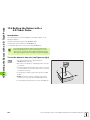
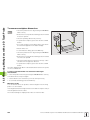
Incremental jog positioning
With incremental jog positioning you can move a machine axis by a
preset distance.
Z
Select the Manual Operation or Electronic Handwheel
mode.
Select incremental jog positioning: Switch the
INCREMENT soft key to ON.
8
8
LINEAR AXES:
Enter the jog increment in mm, e.g. 8 mm, and press
the CONFIRM VALUE soft key.
8
16
X
Finish the entry with the OK soft key.
Press the machine axis direction button as often as
desired
To deactivate the function, press the Switch off soft key.
HEIDENHAIN TNC 320
43
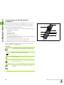
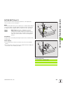
2.2 Moving the Machine Axes
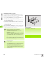
Traversing with the HR 410 electronic
handwheel
The portable HR 410 handwheel is equipped with two permissive
buttons. The permissive buttons are located below the star grip.
You can only move the machine axes when a permissive button is
depressed (machine-dependent function).
1
2
The HR 410 handwheel features the following operating elements:
1
2
3
4
5
6
EMERGENCY STOP button
Handwheel
Permissive buttons
Axis address keys
Actual-position-capture key
Keys for defining the feed rate (slow, medium, fast; the feed rates
are set by the machine tool builder)
7 Direction in which the TNC moves the selected axis
8 Machine function (set by the machine tool builder)
3
4
6
8
4
5
7
The red indicator lights show the axis and feed rate you have selected.
It is also possible to move the machine axes with the handwheel
during a program run if M118 is active.
Procedure:
Select the Electronic Handwheel operating mode.
Press and hold a permissive button.
Select the axis.
Select the feed rate.
Move the active axis in the positive or negative
direction.
or
44
2 Manual Operation and Setup
2.3 Spindle Speed S, Feed Rate F and Miscellaneous Functions M
2.3 Spindle Speed S, Feed Rate F
and Miscellaneous Functions M
Function
In the Manual Operation and Electronic Handwheel operating modes,
you can enter the spindle speed S, feed rate F and the miscellaneous
functions M with soft keys. The miscellaneous functions are
described in Chapter 7 “Programming: Miscellaneous Functions.”
The machine tool builder determines which
miscellaneous functions M are available on your control
and what effects they have.
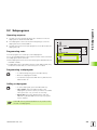
Entering values
Spindle speed S, miscellaneous function M
To enter the spindle speed, press the S soft key.
SPINDLE SPEED S =
1000
Enter the desired spindle speed and confirm your
entry with the machine START button.
The spindle speed S with the entered rpm is started with a
miscellaneous function M. Proceed in the same way to enter a
miscellaneous function M.
Feed rate F
After entering a feed rate F, you must confirm your entry with the OK
key instead of the machine START button.
The following is valid for feed rate F:
If you enter F=0, then the lowest feed rate from the machine
parameter minFeed is effective
If the feed rate entered exceeds the value defined in the machine
parameter maxFeed, then the parameter value is effective.
F is not lost during a power interruption
HEIDENHAIN TNC 320
45
2.3 Spindle Speed S, Feed Rate F and Miscellaneous Functions M
Changing the spindle speed and feed rate
With the override knobs you can vary the spindle speed S and feed
rate F from 0% to 150% of the set value.
The override dial for spindle speed is only functional on
machines with infinitely variable spindle drive.
The machine manufacturer can further limits the ranges of
the override dials (minFeedOverride,
maxFeedOverride, minSpindleOverride and
maxSpindleOverride machine parameters).
The minimum and maximum spindle speeds entered as
machine parameters are not fallen short of or exceeded,
respectively.
If the MP minSpindleOverride=0%, then the setting
spindle override=0 leads to a spindle stop.
46
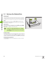
2 Manual Operation and Setup
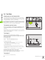
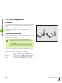
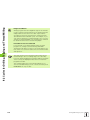
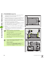
Note
For datum setting with a 3-D touch probe, refer to the
Touch Probe Cycles Manual.
You fix a datum by setting the TNC position display to the coordinates
of a known position on the workpiece.
Preparation
8
8
8
Clamp and align the workpiece.
Insert the zero tool with known radius into the spindle.
Ensure that the TNC is showing the actual position values.
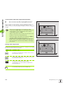
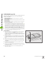
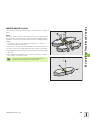
Datum setting with axis keys
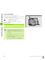
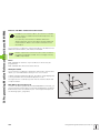
Fragile workpiece?
Y
If the workpiece surface must not be scratched, you can
lay a metal shim of known thickness d on it. Then enter a
tool axis datum value that is larger than the desired datum
by the value d.
Z
X
Y
Select the Manual Operation mode.
X
Move the tool slowly until it touches (scratches) the
workpiece surface.
Select the axis.
DATUM SET Z=
Zero tool in spindle axis: Set the display to a known
workpiece position (here, 0) or enter the thickness d
of the shim. In the tool axis, offset the tool radius.
Repeat the process for the remaining axes.
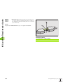
If you are using a preset tool, set the display of the tool axis to the
length L of the tool or enter the sum Z=L+d.
HEIDENHAIN TNC 320
47
2.4 Datum Setting (Without a 3-D Touch Probe)
2.4 Datum Setting (Without a
3-D Touch Probe)
3
Positioning with Manual
Data Input (MDI)
3.1 Programming and Executing Simple Machining Operations
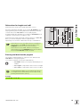
3.1 Programming and Executing
Simple Machining Operations
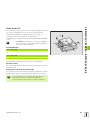
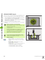
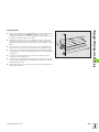
The Positioning with Manual Data Input mode of operation is
particularly convenient for simple machining operations or prepositioning of the tool. You can write the a short program in
HEIDENHAIN conversational programming and execute it
immediately. You can also call TNC cycles. The program is stored in
the file $MDI. In the Positioning with MDI operating mode, the
additional status displays can also be activated.
Positioning with Manual Data Input (MDI)
Select the Positioning with MDI mode of operation.
Program the file $MDI as you wish.
To start program run, press the machine START key.
Z
Limitation
Y
FK free contour programming, programming graphics and
program run graphics, subprograms, program section
repeats, and path compensation cannot be used. The
$MDI file must not contain a program call (PGM CALL).
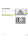
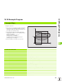
Example 1
A hole with a depth of 20 mm is to be drilled into a single workpiece.
After clamping and aligning the workpiece and setting the datum, you
can program and execute the drilling operation in a few lines.
X
50
50
First you pre-position the tool in L blocks (straight-line blocks) to the
hole center coordinates at a setup clearance of 5 mm above the
workpiece surface. Then drill the hole with Cycle 1 PECKING.
0 BEGIN PGM $MDI MM
1 TOOL DEF 1 L+0 R+5
Define tool: zero tool, radius 5
2 TOOL CALL 1 Z S2000
Call tool: tool axis Z
Spindle speed 2000 rpm
3 L Z+200 R0 FMAX
Retract tool (F MAX = rapid traverse)
4 L X+50 Y+50 R0 FMAX M3
Move the tool at F MAX to a position above the
hole,
Spindle on
6 CYCL DEF 200 DRILLING
50
Define DRILLING cycle
Q200=5
;SET-UP CLEARANCE
Set-up clearance of the tool above the hole
Q201=-15
;DEPTH
Total hole depth (algebraic sign=working direction)
3 Positioning with Manual Data Input (MDI)
;FEED RATE FOR PLNGNG
Feed rate for pecking
Q202=5
;PLUNGING DEPTH
Depth of each infeed before retraction
Q210=0
;DWELL TIME AT TOP
Dwell time after every retraction in seconds
Q203=-10
;SURFACE COORDINATE
Coordinate of the workpiece surface
Q204=20
;2ND SET-UP CLEARANCE
Set-up clearance of the tool above the hole
Q211=0.2
;DWELL TIME AT DEPTH
Dwell time in seconds at the hole bottom
7 CYCL CALL
Call DRILLING cycle
8 L Z+200 R0 FMAX M2
Retract the tool
9 END PGM $MDI MM
End of program
3.1 Programming and Executing Simple Machining Operations
Q206=250
Straight line function L, (see “Straight Line L” on page 128) DRILLING
cycle (see “DRILLING (Cycle 200)” on page 188).
Example 2: Correcting workpiece misalignment on machines
with rotary tables
Use the 3-D touch probe to rotate the coordinate system. See “Touch
Probe Cycles in the Manual and Electronic Handwheel Operating
Modes,” section “Compensating workpiece misalignment,” in the
Touch Probe Cycles User’s Manual.
Write down the rotation angle and cancel the Basic Rotation.
Select operating mode: Positioning with MDI.
Select the axis of the rotary table, enter the rotation
angle you wrote down previously and set the feed
rate. For example: L C+2.561 F50
Conclude entry.
Press the machine START button: The rotation of the
table corrects the misalignment.
HEIDENHAIN TNC 320
51
3.1 Programming and Executing Simple Machining Operations
Protecting and erasing programs in $MDI
The $MDI file is generally intended for short programs that are only
needed temporarily. Nevertheless, you can store a program, if
necessary, by proceeding as described below:
Select the Programming and Editing mode of
operation.
To call the file manager, press the PGM MGT key
(program management).
Move the highlight to the $MDI file.
To select the file copying function, press the COPY
soft key.
TARGET FILE =
BOREHOLE
Enter the name under which you want to save the
current contents of the $MDI file.
Copy the file.
To close the file manager, press the END soft key.
Erasing the contents of the $MDI file is done in a similar way: Instead
of copying the contents, however, you erase them with the DELETE
soft key. The next time you select the operating mode Positioning with
MDI, the TNC will display an empty $MDI file.
If you wish to delete $MDI, then
you must not have selected the Positioning with MDI
mode (not even in the background).
You must not have selected the $MDI file in the
Programming and Editing mode.
you must cancel the editing protection of the $MDI file
For further information, see “Copying a single file,” page 66.
52
3 Positioning with Manual Data Input (MDI)
4
Programming:
Fundamentals of NC,
File Management,
Programming Aids
4.1 Fundamentals
4.1 Fundamentals
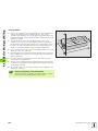
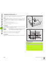
Position encoders and reference marks
The machine axes are equipped with position encoders that register
the positions of the machine table or tool. Linear axes are usually
equipped with linear encoders, rotary tables and tilting axes with angle
encoders.
XMP
X (Z,Y)
When a machine axis moves, the corresponding position encoder
generates an electrical signal. The TNC evaluates this signal and
calculates the precise actual position of the machine axis.
If there is a power interruption, the calculated position will no longer
correspond to the actual position of the machine slide. To recover this
association, incremental position encoders are provided with
reference marks. The scales of the position encoders contain one or
more reference marks that transmit a signal to the TNC when they are
crossed over. From the signal the TNC can re-establish the
assignment of displayed positions to machine positions. For linear
encoders with distance-coded reference marks the machine axes
need to move by no more than 20 mm, for angle encoders by no more
than 20°.
Z
With absolute encoders, an absolute position value is transmitted to
the control immediately upon switch-on. In this way the assignment
of the actual position to the machine slide position is re-established
directly after switch-on.
Y
X
Reference system
A reference system is required to define positions in a plane or in
space. The position data are always referenced to a predetermined
point and are described through coordinates.
The Cartesian coordinate system (a rectangular coordinate system) is
based on the three coordinate axes X, Y and Z. The axes are mutually
perpendicular and intersect at one point called the datum. A
coordinate identifies the distance from the datum in one of these
directions. A position in a plane is thus described through two
coordinates, and a position in space through three coordinates.
Coordinates that are referenced to the datum are referred to as
absolute coordinates. Relative coordinates are referenced to any other
known position (reference point) you define within the coordinate
system. Relative coordinate values are also referred to as incremental
coordinate values.
Z
Y
X
54
4 Programming: Fundamentals of NC, File Management, Programming Aids
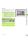
4.1 Fundamentals
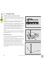
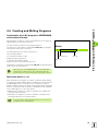
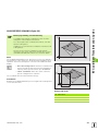
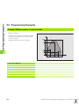
Reference system on milling machines
When using a milling machine, you orient tool movements to the
Cartesian coordinate system. The illustration at right shows how the
Cartesian coordinate system describes the machine axes. The “righthand rule” is illustrated for remembering the three axis directions: the
middle finger points in the positive direction of the tool axis from the
workpiece toward the tool (the Z axis), the thumb points in the positive
X direction, and the index finger in the positive Y direction.
+Z
+Y
The TNC 320 can control up to 4 axes (optionally 5). The axes U, V and
W (which are not presently supported by the TNC 320) are secondary
linear axes parallel to the main axes X, Y and Z, respectively. Rotary
axes are designated as A, B and C. The illustration at lower right shows
the assignment of secondary axes and rotary axes to the main axes.
+X
+Z
+X
+Y
Z
Y
W+
C+
B+
V+
X
A+
U+
HEIDENHAIN TNC 320
55
4.1 Fundamentals
Polar coordinates
If the production drawing is dimensioned in Cartesian coordinates, you
also write the part program using Cartesian coordinates. For parts
containing circular arcs or angles it is often simpler to give the
dimensions in polar coordinates.
Y
While the Cartesian coordinates X, Y and Z are three-dimensional and
can describe points in space, polar coordinates are two-dimensional
and describe points in a plane. Polar coordinates have their datum at a
circle center (CC), or pole. A position in a plane can be clearly defined
by the:
Polar Radius, the distance from the circle center CC to the position,
and the
Polar Angle, the size of the angle between the reference axis and
the line that connects the circle center CC with the position.
PR
PA2
PA3
PR
PR
PA1
10
0°
CC
X
30
See figure at upper right.
Setting the pole and the angle reference axis
The pole is set by entering two Cartesian coordinates in one of the
three planes. These coordinates also set the reference axis for the
polar angle PA.
Y
Z
Coordinates of the pole
(plane)
Reference axis of the angle
X/Y
+X
Y/Z
+Y
Z
Y
X
Z/X
+Z
Z
Y
X
X
56
4 Programming: Fundamentals of NC, File Management, Programming Aids
4.1 Fundamentals
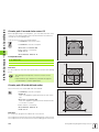
Absolute and incremental workpiece positions
Absolute workpiece positions
Absolute coordinates are position coordinates that are referenced to
the datum of the coordinate system (origin). Each position on the
workpiece is uniquely defined by its absolute coordinates.
Example 1: Holes dimensioned in absolute coordinates
Hole 1
X = 10 mm
Y = 10 mm
Hole 2
X = 30 mm
Y = 20 mm
Hole 3
X = 50 mm
Y = 30 mm
Y
13
30
12
20
1
10
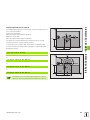
Incremental workpiece positions
Incremental coordinates are referenced to the last programmed
nominal position of the tool, which serves as the relative (imaginary)
datum. When you write a part program in incremental coordinates,
you thus program the tool to move by the distance between the
previous and the subsequent nominal positions. This is why it is also
referred to as a chain dimension.
X
10
To program a position in incremental coordinates, enter the prefix “I”
before the axis.
50
30
Y
Example 2: Holes dimensioned in incremental coordinates
15
10
X = 10 mm
Y = 10 mm
Hole 5, relative to 4
X = 20 mm
Y = 10 mm
16
10
Absolute coordinates of hole 4
Hole 6, relative to 5
X = 20 mm
Y = 10 mm
14
10
X
20
20
10
Absolute and incremental polar coordinates
Absolute polar coordinates always refer to the pole and the reference
axis.
Incremental polar coordinates always refer to the last programmed
nominal position of the tool.
Y
+IPR
PR
PR
+IPA +IPA
PR
PA
10
0°
CC
X
30
HEIDENHAIN TNC 320
57
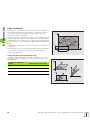
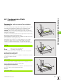
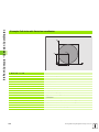
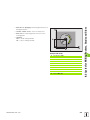
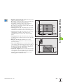
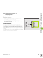
A production drawing identifies a certain form element of the
workpiece, usually a corner, as the absolute datum. When setting the
datum, you first align the workpiece along the machine axes, and then
move the tool in each axis to a defined position relative to the
workpiece. Set the display of the TNC either to zero or to a known
position value for each position. This establishes the reference system
for the workpiece, which will be used for the TNC display and your part
program.
Z
MAX
Y
X
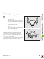
If the production drawing is dimensioned in relative coordinates,
simply use the coordinate transformation cycles (see “Coordinate
Transformation Cycles” on page 302).
If the production drawing is not dimensioned for NC, set the datum at
a position or corner on the workpiece which is suitable for deducing
the dimensions of the remaining workpiece positions.
MIN
The fastest, easiest and most accurate way of setting the datum is by
using a 3-D touch probe from HEIDENHAIN. See “Setting the Datum
with a 3-D Touch Probe” in the Touch Probe Cycles User’s Manual.
17
750
16
150
0
15
320
13
14
-150
0
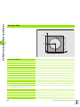
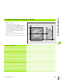
Example
The workpiece drawing at right shows holes (1 to 4) whose
dimensions are shown with respect to an absolute datum with the
coordinates X=0, Y=0. The holes (5 to 7) are dimensioned with respect
to a relative datum with the absolute coordinates X=450, Y=750. With
the DATUM SHIFT cycle you can temporarily set the datum to the
position X=450, Y=750, to be able to program the holes (5 to 7)
without further calculations.
Y
300±0,1
4.1 Fundamentals
Setting the datum
1
325 450
12
900
X
950
58
4 Programming: Fundamentals of NC, File Management, Programming Aids
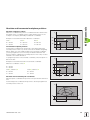
4.2 File Management: Fundamentals
4.2 File Management:
Fundamentals
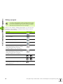
Files
Files in the TNC
Type
Programs
In HEIDENHAIN format
In ISO format
.H
.I
Tables for
Tools
Tool changers
Datums
Touch probes
.T
.TCH
.D
.TP
When you write a part program on the TNC, you must first enter a file
name. The TNC saves the program as a file with the same name. The
TNC can also save texts and tables as files.
The TNC provides a special file management window in which you can
easily find and manage your files. Here you can call, copy, rename and
erase files.
With the TNC you can manage and save files up to a total size of
10 MB.
File names
When you store programs, tables and texts as files, the TNC adds an
extension to the file name, separated by a point. This extension
indicates the file type.
PROG20
.H
File name
File type
File names should not exceed 25 characters, otherwise the TNC
cannot display the entire file name. The characters ; * \ / “ ? < > .
are not permitted in file names.
You cannot use any other special characters, including
space characters, in file names.
The maximum limit for the path and file name together is
256 characters (see “Paths” on page 61).
HEIDENHAIN TNC 320
59
4.2 File Management: Fundamentals
Screen keypad
You can enter letters and special characters with the screen keypad or
(if available) with a PC keyboard connected over the USB port.
Enter the text with the screen keypad
8 Press the GOTO key if you want to enter a text, for example a
program name or directory name, using the screen keypad
8 The TNC opens a window in which the numeric entry field 1 of the
TNC is displayed with the corresponding letters assigned
8 You can move the cursor to the desired character by repeatedly
pressing the respective key
8 Wait until the selected character is transferred to the entry field
before you enter the next character
8 Use the OK soft key to load the text into the open dialog field
Use the abc/ABC soft key to select upper or lower case. If your
machine tool builder has defined additional special characters, you can
call them with the SPECIAL CHARACTER soft key and insert them.
To delete individual characters, use the Backspace soft key.
Data backup
We recommend saving newly written programs and files on a PC at
regular intervals.
HEIDENHAIN provides a backup function for this purpose in the data
transfer software TNCremoNT. Your machine tool builder can provide
you with a copy of TNCBACK.EXE.
1
You additionally need a data medium on which all machine-specific
data, such as the PLC program, machine parameters, etc., are stored.
Please contact your machine tool builder for more information on both
the backup program and the floppy disk.
60
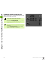
4 Programming: Fundamentals of NC, File Management, Programming Aids
4.3 Working with the File Manager
4.3 Working with the File Manager
Directories
If you save many programs in the TNC, we recommend that you save
your files in directories (folders) so that you can easily find your data.
You can divide a directory into further directories, which are called
subdirectories. With the –/+ key or ENT you can show or hide the
subdirectories.
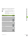
Paths
A path indicates the drive and all directories and subdirectories under
which a file is saved. The individual names are separated by a
backslash “\”.
Example
On drive TNC:\ the subdirectory AUFTR1 was created. Then, in the
directory AUFTR1 the directory NCPROG was created and the part
program PROG1.H was copied into it. The part program now has the
following path:
TNC:\
AUFTR1
NCPROG
WZTAB
A35K941
TNC:\AUFTR1\NCPROG\PROG1.H
ZYLM
The chart at right illustrates an example of a directory display with
different paths.
TESTPROG
HUBER
KAR25T
HEIDENHAIN TNC 320
61
4.3 Working with the File Manager
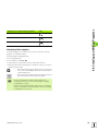
Overview: Functions of the file manager
Function
Soft key
Copy (and convert) individual files
Display a specific file type
Display the last 10 files that were selected
Erase a file or directory
Mark a file
Rename a file
Protect a file against editing and erasure
Cancel file protection
Manage network drives
Copy a directory
Display all the directories of a particular drive
Delete directory with all its subdirectories
Sort files by properties
Create new file
Select the editor
62
4 Programming: Fundamentals of NC, File Management, Programming Aids
4.3 Working with the File Manager
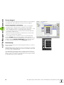
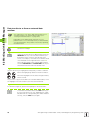
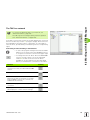
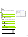
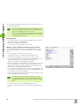
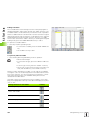
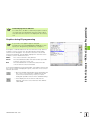
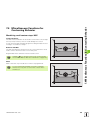
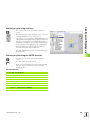
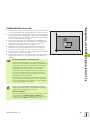
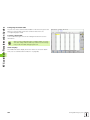
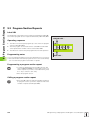
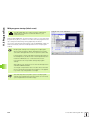
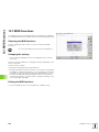
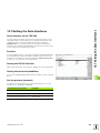
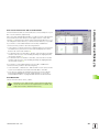
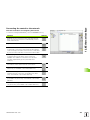
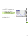
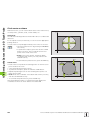
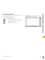
Calling the file manager
Press the PGM MGT key: the TNC displays the file
management window (Figure at upper right shows
the factory default setting.) If the TNC displays a
different screen layout, press the WINDOW soft key.)
The narrow window on the left 1 shows the available drives and
directories. Drives designate devices with which data are stored or
transferred. One drive is the internal memory of the TNC. Other drives
are the RS232, RS422, Ethernet and USB interfaces, which you can
used, for example, to connect a personal computer or other storage
device. A drive is always identified by a file symbol to the left and the
directory name to the right. The TNC displays a subdirectory to the
right of and below its parent directory. A box with the + symbol in front
of the folder symbol indicates that there are further subdirectories,
which can be shown with the –/+ key or ENT.
1
2
The wide window on the right 2 shows you all files that are stored in
the selected directory. Each file is shown with additional information,
illustrated in the table below.
Display
Meaning
FILE NAME
Name with an extension, separated by a dot
(file type)
BYTE
File size in bytes
STATUS
File properties:
E
Program is selected in the Programming and
Editing mode of operation.
S
Program is selected in the Test Run mode of
operation.
M
Program is selected in a Program Run mode
of operation.
File is protected against editing and erasure.
DATUM
Date the file was last changed
TIME
Time the file was last changed
HEIDENHAIN TNC 320
63
4.3 Working with the File Manager
Selecting drives, directories and files
Calling the file manager
With the arrow keys or the soft keys, you can move the highlight to
the desired position on the screen:
Moves the highlight from the left to the right window,
and vice versa.
Moves the highlight up and down within a window.
Moves the highlight one page up or down within a
window.
Step 1: Select drive
Move the highlight to the desired drive in the left window:
Select a drive: Press the SELECT soft key or the ENT
key.
or
Step 2: Select a directory
Move the highlight to the desired directory in the left-hand window—
the right-hand window automatically shows all files stored in the
highlighted directory.
64
4 Programming: Fundamentals of NC, File Management, Programming Aids
4.3 Working with the File Manager
Step 3: Select a file
Press the SELECT TYPE soft key.
Press the soft key for the desired file type, or
Press the SHOW ALL soft key to display all files, or
Move the highlight to the desired file in the right window.
or
The selected file is opened in the operating mode
from which you have called the File Manager: Press
the SELECT soft key or the ENT key.
Creating a new directory
Move the highlight in the left window to the directory in which you
want to create a subdirectory.
NEW
Enter the new file name, and confirm with ENT.
DIRECTORY NAME?
Press the OK soft key to confirm, or
abort with the CANCEL soft key.
HEIDENHAIN TNC 320
65
4.3 Working with the File Manager
Copying a single file
8
Move the highlight to the file you wish to copy.
8 Press the COPY soft key to select the copy function.
The TNC opens a pop-up window.
8
Enter the name of the destination file and confirm your
entry with the ENT key or OK soft key: The TNC
copies the file to the active directory or to the
corresponding destination directory. The original file
is retained.
Copying a directory
Move the highlight in the left window onto the directory you want to
copy. Then press the COPY DIR soft key instead of the COPY soft key.
Subdirectories can be copied by the TNC at the same time.
Making a setting in a selection box
In various dialogs, the TNC opens a pop-up window in which you can
make settings in selection boxes.
8
8
8
Move the cursor into the desired selection box and press the GOTO
key.
Use the arrow keys to position the cursor to the required setting.
With the OK soft key you confirm the value, and with the CANCEL
soft key you discard the selection.
66
4 Programming: Fundamentals of NC, File Management, Programming Aids
4.3 Working with the File Manager
Choosing one of the last 10 files selected
Calling the file manager
Display the last 10 files selected: Press the LAST
FILES soft key.
Use the arrow keys to move the highlight to the file you wish to select:
Moves the highlight up and down within a window.
Select a file: Press the OK soft key or ENT
or
Deleting a file
8
Move the highlight to the file you want to delete.
8 To select the erasing function, press the DELETE soft
key.
8
To confirm, press the OK soft key.
8
To cancel deletion, press the CANCEL soft key.
Deleting a directory
8
8
Delete all files and subdirectories stored in the directory that you
want to delete.
Move the highlight to the directory you want to delete.
8 To select delete function, press the DELETE ALL soft
key. The TNC asks whether you really want to erase
the subdirectories and files.
8
To confirm, press the OK soft key.
8
To cancel deletion, press the CANCEL soft key.
HEIDENHAIN TNC 320
67
4.3 Working with the File Manager
Marking files
Marking functions
Soft key
Mark a single file
Mark all files in the directory
Unmark a single file
Unmark all files
Some functions, such as copying or erasing files, can not only be used
for individual files, but also for several files at once. To mark several
files, proceed as follows:
Move the highlight to the first file.
To display the marking functions, press the TAG soft
key.
Mark a file by pressing the TAG FILE soft key.
Move the highlight to the next file you wish to mark:
To mark more files, press the MARK FILE soft key.
To copy the marked files, with the back soft key,
leave the TAG function
To copy the marked files, select the COPY soft key.
To delete the marked files, press the back soft key to
exit the marking function and then press the DELETE
soft key.
68
4 Programming: Fundamentals of NC, File Management, Programming Aids
4.3 Working with the File Manager
Renaming a file
8
Move the highlight to the file you wish to rename.
8 Select the renaming function.
8
Enter the new file name; the file type cannot be
changed.
8
To rename: Press the OK soft key or the ENT key.
File sorting
8
Select the folder in which you wish to sort the files.
8 Select the SORT soft key.
8
Select the soft key with the corresponding display
criterion.
Additional functions
Protecting a file / Canceling file protection
8 Move the highlight to the file you want to protect.
8 To select the additional functions, press the MORE
FUNCTIONS soft key.
8
To enable file protection, press the PROTECT soft
key. The file is distinguished by a symbol.
8
To cancel file protection, proceed in the same way
using the UNPROTECT soft key.
Select the editor
8 Move the highlight in the right window onto the file you want to
open.
8 To select the additional functions, press the MORE
FUNCTIONS soft key.
8
To select the editor with which to open the selected
file, press the SELECT EDITOR soft key.
8
Mark the desired editor.
8
Press the OK soft key to open the file.
Activate or deactivate USB devices
8 To select the additional functions, press the MORE
FUNCTIONS soft key.
8
Shift the soft-key row.
8
Select the soft key for activating or deactivating.
HEIDENHAIN TNC 320
69
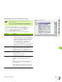
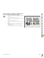
4.3 Working with the File Manager
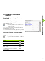
Data transfer to or from an external data
medium
You might have to set up the data interface before you
can transfer data to an external data medium (see
“Setting the Data Interfaces” on page 427).
Depending on the data transfer software you use,
problems can occur occasionally when you transmit data
over a serial interface. They can be overcome by repeating
the transmission.
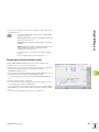
Call the file manager.
1
2
Select the screen layout for data transfer: press the
WINDOW soft key. Select the desired directory in
both halves of the screen. In the left half of the
screen, for example, 1 the TNC shows all files saved
on its hard disk. In the right half of the screen 2 it
shows all files saved on the external data medium.
Use the SHOW FILES and SHOW TREE soft keys to
switch between the folder view and file view.
Use the arrow keys to highlight the file(s) that you want to transfer:
Moves the highlight up and down within a window.
Moves the highlight from the left to the right window,
and vice versa.
If you wish to copy from the TNC to the external data medium, move
the highlight in the left window to the file to be transferred.
To transfer a single file, position the highlight on the desired file.
To transfer several files: Press the TAG soft key (in
the second soft-key row; see “Marking files,” page
68) and mark the corresponding files. With the back
soft key, exit the TAG function again.
70
4 Programming: Fundamentals of NC, File Management, Programming Aids
4.3 Working with the File Manager
Press the COPY soft key.
Confirm with the OK soft key or with the ENT key. For long programs,
a status window appears on the TNC informing you of the copying
progress.
To end data transfer, move the highlight into the left
window and then press the WINDOW soft key. The
standard file manager window is displayed again.
To select another directory in the split-screen display,
press the SHOW TREE soft key. If you press the SHOW
FILES soft key, the TNC shows the content of the
selected directory!
HEIDENHAIN TNC 320
71
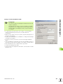
4.3 Working with the File Manager
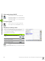
Copying files into another directory
8
8
Select the screen layout with the two equally sized windows.
To display directories in both windows, press the SHOW TREE soft
key.
In the right window
8
Move the highlight to the directory to copy the files to and display
the files in this directory with the SHOW FILES soft key.
In the left window
8
Select the directory with the files to copy and press the SHOW
FILES soft key to display them.
8 Display the file marking functions.
8
Move the highlight to the files to be copied and mark
them. You can mark several files in this way, if
desired.
8
Copy the marked files into the target directory.
Additional marking functions: see “Marking files,” page 68.
If you have marked files in the left and right windows, the TNC copies
from the directory in which the highlight is located.
Overwriting files
If you copy files into a directory in which other files are stored under
the same name, the TNC will reply with a “protected file” error
message. Use the TAG function to overwrite the file anyway:
8
8
To overwrite two or more files, mark them in the "existing files" popup window and press the OK soft key.
To leave the files as they are, press the CANCEL soft key.
72
4 Programming: Fundamentals of NC, File Management, Programming Aids
4.3 Working with the File Manager
The TNC in a network
To connect the Ethernet card to your network, see
“Ethernet Interface,” page 432.
The TNC logs error messages during network operation
(see “Ethernet Interface” on page 432).
2
1
If the TNC is connected to a network, the TNC displays the connected
drives in the directory window 1 (see figure at right). All the functions
described above (selecting a drive, copying files, etc.) also apply to
network drives, provided that you have been given the corresponding
rights.
Connecting and disconnecting a network drive
8 To select the program management: Press the PGM
MGT key. If necessary, press the WINDOW soft key
to set up the screen as it is shown at the upper right.
8
To manage the network drives: Press the NETWORK
soft key (second soft-key row). In the right-hand
window 2 the TNC shows the network drives
available for access. With the soft keys described
below you can define the connection for each drive.
Function
Soft key
Establish the network connection. If the
connection is active, the TNC marks the Mnt
column.
Delete network connection
Automatically establish network connection
whenever the TNC is switched on. The TNC
marks the Auto column if the connection is
established automatically.
Use the PING ping function to test your network
connection
If you press the NETWORK INFO soft key, the
TNC displays the current network settings
HEIDENHAIN TNC 320
73
4.3 Working with the File Manager
USB devices on the TNC
Backing up data from or loading onto the TNC is especially easy with
USB devices. The TNC supports the following USB block devices:
Floppy disk drives with FAT/VFAT file system
Memory sticks with the FAT/VFAT file system
Hard disks with the FAT/VFAT file system
CD-ROM drives with the Joliet (ISO 9660) file system
The TNC automatically detects these types of USB devices when
connected. The TNC does not support USB devices with other file
systems (such as NTFS). After connection, the TNC displays an error
message.
The TNC also displays an error message if you connect a
USB hub. In this case simply acknowledge the message
with the CE key.
In theory, you should be able to connect all USB devices
with the file systems mentioned above to the TNC. If
problems occur nevertheless, please contact
HEIDENHAIN.
The USB devices appear as separate drives in the directory tree, so
you can use the file-management functions described in the earlier
chapters correspondingly.
In order to remove a USB device, you must proceed as follows:
8
To call the file manager, press the PGM MGT soft key.
8
Select the left window with the arrow key.
8
Use the arrow keys to select the USB device to be
removed.
8
Scroll through the soft-key row.
8
Select additional functions.
8
Select the function for removing USB devices: The
TNC removes the USB device from the directory tree.
8
Exit program management.
In order to re-establish a connection with a USB device that has been
removed, press the following soft key:
8
74
Select the function for reconnection of USB devices.
4 Programming: Fundamentals of NC, File Management, Programming Aids
4.4 Creating and Writing Programs
4.4 Creating and Writing Programs
Organization of an NC program in HEIDENHAIN
conversational format
A part program consists of a series of program blocks. The figure at
right illustrates the elements of a block.
The TNC numbers the blocks in ascending sequence.
The first block of a program is identified by BEGIN PGM, the program
name and the active unit of measure.
Blocks
10 L X+10 Y+5 R0 F100 M3
The subsequent blocks contain information on:
the workpiece blank
tool definitions and tool calls
approaching a safe position
feed rates and spindle speeds
path contours, cycles and other functions
Path function
Words
Block no.
The last block of a program is identified by END PGM, the program name
and the active unit of measure.
After each tool call, HEIDENHAIN recommends always
traversing to a safe position, from which the TNC can
position the tool for machining without causing a collision!
Define the blank: BLK
FORM
After initiating a new program, you define a cuboid workpiece blank.
To define the workpiece blank, press the SPEC FCT soft key and then
the BLK FORM soft key. This definition is needed for the TNC’s
graphic simulation feature. The sides of the workpiece blank lie parallel
to the X, Y and Z axes and can be up to 100 000 mm long. The blank
form is defined by two of its corner points:
MIN point: the smallest X, Y and Z coordinates of the blank form,
entered as absolute values.
MAX point: the largest X, Y and Z coordinates of the blank form,
entered as absolute or incremental values.
You only need to define the blank form if you wish to run
a graphic test for the program!
HEIDENHAIN TNC 320
75
4.4 Creating and Writing Programs
Creating a new part program
You always enter a part program in the Programming and Editing
mode of operation. An example of program initiation:
Select the Programming and Editing operating mode.
Press the PGM MGT key to call the file manager.
Select the directory in which you wish to store the new program:
FILE NAME = 123.H
Enter the new program name and confirm your entry
with the ENT key.
To select the unit of measure, press the MM or INCH
soft key. The TNC switches the screen layout and
initiates the dialog for defining the BLK FORM.
WORKING SPINDLE AXIS X/Y/Z ?
Enter the spindle axis.
DEF BLK FORM: MIN CORNER?
0
Enter in sequence the X, Y and Z coordinates of the
MIN point.
0
-40
76
4 Programming: Fundamentals of NC, File Management, Programming Aids
4.4 Creating and Writing Programs
DEF BLK FORM: MAX CORNER?
100
Enter in sequence the X, Y and Z coordinates of the
MAX point.
100
0
Example: Display the BLK form in the NC program
0 BEGIN PGM NEW MM
Program begin, name, unit of measure
1 BLK FORM 0.1 Z X+0 Y+0 Z-40
Spindle axis, MIN point coordinates
2 BLK FORM 0.2 X+100 Y+100 Z+0
MAX point coordinates
3 END PGM NEW MM
Program end, name, unit of measure
The TNC automatically generates the block numbers as well as the
BEGIN and END blocks.
If you do not wish to define a blank form, cancel the dialog
at Working spindle axis X/Y/Z by pressing the DEL key!
The TNC can display the graphics only if the shortest side
is at least 50 µm long and the longest side is no longer
than 99 999.999 mm.
HEIDENHAIN TNC 320
77
4.4 Creating and Writing Programs
Programming tool movements in conversational
format
To program a block, initiate the dialog by pressing a function key. In the
screen headline, the TNC then asks you for all the information
necessary to program the desired function.
Example of a dialog
Dialog initiation
COORDINATES?
10
20
Enter the target coordinate for the X axis
Enter the target coordinate for the Y axis, and go to
the next question with ENT
RADIUS COMP. RL/RR/NO COMP. ?
Enter “No radius compensation” and go to the next
question with ENT.
FEED RATE F=? / F MAX = ENT
100
Enter a feed rate of 100 mm/min for this path contour;
go to the next question with ENT.
MISCELLANEOUS FUNCTION M?
Enter the miscellaneous function M3 “spindle ON”;
pressing the ENT key terminates this dialog.
3
The program-block window displays the following line:
3 L X+10 Y+5 R0 F100 M3
Functions for setting the feed rate
Soft key
Rapid traverse
Traverse feed rate automatically calculated in
TOOL CALL
Move at the programmed feed rate (unit of
measure is mm/min)
78
4 Programming: Fundamentals of NC, File Management, Programming Aids
4.4 Creating and Writing Programs
Functions for conversational guidance
Key
Ignore the dialog question
End the dialog immediately
Abort the dialog and erase the block
Actual position capture
The TNC enables you to transfer the current tool position into the
program, for example during
Positioning-block programming
Cycle programming
Tool definition with TOOL DEF
To transfer the correct position values, proceed as follows:
8
Place the input box at the position in the block where you want to
insert a position value.
8 Select the actual-position-capture function: In the softkey row the TNC displays the axes whose positions
can be transferred.
8
Select the axis: The TNC writes the current position of
the selected axis into the active input box.
In the working plane the TNC always captures the
coordinates of the tool center, even though tool radius
compensation is active.
In the tool axis the TNC always captures the coordinates
of the tool tip and thus always takes the active tool length
compensation into account.
HEIDENHAIN TNC 320
79
4.4 Creating and Writing Programs
Editing a program
You cannot edit a program while it is being run by the TNC
in a machine operating mode. The TNC allows you to place
the cursor in the block, but it does not save the changes
and responds instead with an error message.
While you are creating or editing a part program, you can select any
desired line in the program or individual words in a block with the
arrow keys or the soft keys:
Function
Soft key/key
Go to previous page
Go to next page
Go to beginning of program
Go to end of program
Change the position of the current block on
the screen: Press this soft key to display
additional program blocks that are
programmed before the current block.
Change the position of the current block on
the screen: Press this soft key to display
additional program blocks that are
programmed after the current block.
Move from one block to the next
Select individual words in a block
To select a certain block, press the GOTO key,
enter the desired block number, and confirm
with the ENT key.
80
4 Programming: Fundamentals of NC, File Management, Programming Aids
4.4 Creating and Writing Programs
Function
Soft key/key
Set the selected word to zero
Erase an incorrect number
Clear a (non-blinking) error message
Delete the selected word
Delete the selected block
Erase cycles and program sections
Insert the block that was last edited or deleted
Inserting blocks at any desired location
8 Select the block after which you want to insert a new block and
initiate the dialog.
Editing and inserting words
8 Select a word in a block and overwrite it with the new one. The plainlanguage dialog is available while the word is highlighted.
8 To accept the change, press the END key.
If you want to insert a word, press the horizontal arrow key repeatedly
until the desired dialog appears. You can then enter the desired value.
Looking for the same words in different blocks
Set the AUTO DRAW soft key to OFF.
To select a word in a block, press the arrow keys
repeatedly until the highlight is on the desired word.
Select a block with the arrow keys.
HEIDENHAIN TNC 320
81
4.4 Creating and Writing Programs
The word that is highlighted in the new block is the same as the one
you selected previously.
If you have started a search in a very long program, the
TNC shows a progress display window. You then have the
option of canceling the search via soft key.
In the tool axis the TNC always captures the coordinates
of the tool tip and thus always takes the active tool length
compensation into account.
Finding any text
8 To select the search function, press the FIND soft key. The TNC
displays the dialog prompt Find text:
8 Enter the text that you wish to find.
8 To find the text, press the EXECUTE soft key.
Marking, copying, deleting and inserting program sections
The TNC provides certain functions for copying program sections
within an NC program or into another NC program—see the table
below.
To copy a program section, proceed as follows:
8
8
8
8
8
8
Select the soft-key row containing the marking functions.
Select the first (last) block of the section you wish to copy.
To mark the first (last) block: Press the SELECT BLOCK soft key. The
TNC then highlights the first character of the block and
superimposes the soft key CANCEL SELECTION.
Move the highlight to the last (first) block of the program section you
wish to copy or delete. The TNC shows the marked blocks in a
different color. You can end the marking function at any time by
pressing the CANCEL SELECTION soft key.
To copy the selected program section, press the COPY BLOCK soft
key. To delete the selected section, press the DELETE BLOCK soft
key. The TNC stores the selected block.
Using the arrow keys, select the block after which you wish to insert
the copied (deleted) program section.
To insert the section into another program, select the
corresponding program using the file manager and then
mark the block after which you wish to insert the copied
block.
8
8
To insert the block, press the INSERT BLOCK soft key.
To end the marking function, press the CANCEL SELECTION soft
key.
82
4 Programming: Fundamentals of NC, File Management, Programming Aids
4.4 Creating and Writing Programs
Function
Soft key
Switch marking function on
Switch marking function off
Delete marked block
Insert block that is stored in the buffer memory
Copy marked block
The TNC search function
With the search function of the TNC, you can search for any text within
a program and replace it by a new text, if required.
Searching for texts
8 If required, select the block containing the word you wish to find.
8 Select the search function: The TNC superimposes
the search window and displays the available search
functions in the soft-key row (see table of search
functions).
+40
8
Enter the text to be searched for. Please note that the
search is case-sensitive.
8
Start the search process: The TNC displays the
available search options in the soft-key row (see the
table of search options on the next page).
8
Start the search process: The TNC moves to the next
block containing the text you are searching for.
8
Repeat the search process: The TNC moves to the
next block containing the text you are searching for.
8
End the search function.
HEIDENHAIN TNC 320
83
4.4 Creating and Writing Programs
Find/Replace any text
The find/replace function is not possible if
a program is protected or
the program is currently being run by the TNC.
When using the REPLACE ALL function, ensure that you
do not accidentally replace text that you do not want to
change. Once replaced, such text cannot be restored.
8
If required, select the block containing the word you wish to find.
8 Select the Search function: The TNC superimposes
the search window and displays the available search
functions in the soft-key row.
84
8
Activate the Replace function: The TNC superimposes
a window for entering the text to be inserted.
8
Enter the text to be searched for. Please note that the
search is case-sensitive. Then confirm with the ENT
key.
8
Enter the text to be inserted. Please note that the
entry is case-sensitive.
8
Start the search process: The TNC displays the
available search options in the soft-key row (see the
table of search options).
8
If required, change the search options.
8
Start the search process: The TNC moves to the next
occurrence of the text you are searching for.
8
To replace the text and then move to the next
occurrence of the text, press the REPLACE soft key.
To replace all text occurrences, press the REPLACE
soft key. To skip the text and move to its next
occurrence press the FIND soft key.
8
End the search function.
4 Programming: Fundamentals of NC, File Management, Programming Aids
4.5 Interactive Programming Graphics
4.5 Interactive Programming
Graphics
Generating / Not generating graphics during
programming:
While you are writing the part program, you can have the TNC
generate a 2-D pencil-trace graphic of the programmed contour.
8
To switch the screen layout to displaying program blocks to the left
and graphics to the right, press the SPLIT SCREEN key and
PGM + GRAPHICS soft key.
8 Set the AUTO DRAW soft key to ON. While you are
entering the program lines, the TNC generates each
path contour you program in the graphics window in
the right screen half.
If you do not wish to have graphics generated during programming,
set the AUTO DRAW soft key to OFF.
Even when AUTO DRAW is switched ON, graphics are not generated
for program section repeats.
Generating a graphic for an existing program
8
Use the arrow keys to select the block up to which you want the
graphic to be generated, or press GOTO and enter the desired block
number.
8 To generate graphics, press the RESET + START soft
key.
Additional functions:
Function
Soft key
Generate a complete graphic
Generate interactive graphic blockwise
Generate a complete graphic or complete it after
RESET + START
Stop the programming graphics. This soft key
only appears while the TNC is generating the
interactive graphics
HEIDENHAIN TNC 320
85
4.5 Interactive Programming Graphics
Block number display ON/OFF
8
Shift the soft-key row (see figure at upper right).
8
To show block numbers: Set the SHOW OMIT BLOCK
NR. soft key to SHOW.
8
To omit block numbers: Set the SHOW OMIT BLOCK
NR. soft key to OMIT.
Erasing the graphic
8
Shift the soft-key row (see figure at upper right).
8
Delete graphic: Press CLEAR GRAPHIC soft key.
Magnifying or reducing a detail
You can select the graphics display by selecting a detail with the frame
overlay. You can now magnify or reduce the selected detail.
8
Select the soft-key row for detail magnification/reduction (second
row, see figure at center right).
The following functions are available:
Function
Soft key
Show and move the frame overlay. Press and
hold the desired soft key to move the frame
overlay.
Reduce the frame overlay—press and hold the
soft key to reduce the detail.
Enlarge the frame overlay—press and hold the
soft key to magnify the detail.
8
Confirm the selected area with the WINDOW DETAIL
soft key.
With the WINDOW BLK FORM soft key, you can restore the original
section.
86
4 Programming: Fundamentals of NC, File Management, Programming Aids
4.6 Adding Comments
4.6 Adding Comments
Function
You can add comments to a part program to explain program steps or
make general notes.
If the TNC cannot show the entire comment on the
screen, the >> sign is displayed.
Adding a comment line
8
8
8
8
Select the block after which the comment is to be inserted.
Press the SPECIAL TNC FUNCTIONS soft key.
Select the COMMENT soft-key.
Enter your comment using the screen keyboard (GOTO key) or a
USB keyboard, if available, and conclude the block by pressing the
END key.
Functions for editing of the comment
Function
Soft key
Jump to beginning of comment
Jump to end of comment
Jump to the beginning of a word. Words must be
separated by a space.
Jump to the end of a word. Words must be
separated by a space.
Switch between insert mode and overwrite
mode
HEIDENHAIN TNC 320
87
4.7 Integrated Pocket Calculator
4.7 Integrated Pocket Calculator
Operation
The TNC features an integrated pocket calculator with the basic
mathematical functions.
8
8
Use the CALC key to show and hide the on-line pocket calculator.
Use soft keys to enter the calculator functions.
Mathematical function
Command (key)
Addition
+
Subtraction
–
Multiplication
*
Division
/
Parenthetic calculations
()
Arc cosine
ARC
Sine
SIN
Cosine
COS
Tangent
TAN
Powers of values
X^Y
Square root
SQRT
Inversion
1/x
p (3.14159265359)
PI
Add value to buffer memory
M+
Save the value to buffer
memory
MS
Recall from buffer memory
MR
Delete buffer memory contents
MC
Natural logarithm
LN
Logarithm
LOG
Exponential function
e^x
Check algebraic sign
SGN
Form the absolute value
ABS
Truncate decimal places
INT
88
4 Programming: Fundamentals of NC, File Management, Programming Aids
Command (key)
Truncate integers
FRAC
Modulus operator
MOD
Select view
View
Delete value
DEL
4.7 Integrated Pocket Calculator
Mathematical function
To transfer the calculated value into the program,
8 Select the word into which the calculated value is to be transferred
by using the arrow keys.
8 Superimpose the on-line calculator by using the CALC key and
perform the desired calculation.
8 Press the actual-position-capture key for the TNC to superimpose a
soft-key row.
8 Press the CALC soft key for the TNC to transfer the value into the
active input box and to close the calculator.
HEIDENHAIN TNC 320
89
4.8 The Error Messages
4.8 The Error Messages
Display of errors
The TNC generates error messages when it detects problems such
as:
Incorrect data input
Logical errors in the program
Contour elements that are impossible to machine
Incorrect use of the touch probe system
When an error occurs, it is displayed in red type in the header. Long
and multi-line error messages are displayed in abbreviated form. If an
error occurs in the background mode, the word “Error” is displayed in
red type. Complete information on all pending errors is shown in the
error window.
If a rare “processor check error” should occur, the TNC automatically
opens the error window. You cannot remove such an error. Shut down
the system and restart the TNC.
The error message is displayed in the header until it is cleared or
replaced by a higher-priority error.
An error message that contains a program block number was caused
by an error in the indicated block or in the preceding block.
Open the error window
8
Press the ERR key. The TNC opens the error window
and displays all accumulated error messages.
Close the error window
90
8
Press the END soft key—or
8
Press the ERR key. The TNC closes the error window.
4 Programming: Fundamentals of NC, File Management, Programming Aids
4.8 The Error Messages
Detailed error messages
The TNC displays possible causes of the error and suggestions for
solving the problem:
8
Open the error window.
8 Information on the error cause and corrective action:
Position the highlight on the error message and press
the MORE INFO soft key. The TNC opens a window
with information on the error cause and corrective
action.
8
Leave Info: Press the MORE INFO soft key again.
INTERNAL INFO soft key
The INTERNAL INFO soft key supplies information on the error
message. This information is only required if servicing is needed.
8
Open the error window.
8 Detailed information about the error message:
Position the highlight on the error message and press
the INTERNAL INFO soft key. The TNC opens the
window with internal information about the error
8
To leave Details, press the INTERNAL INFO soft key
again.
Deleting errors
Clearing errors outside of the error window:
8
To clear the error/message in the header: Press the
CE button.
In some operating modes (such as the Editing mode), the
CE button cannot be used to clear the error, since the
button is reserved for other functions.
Clearing more than one error:
8
Open the error window.
8 Clear individual errors: Position the highlight on the
error message and press the DELETE soft key.
8
Clear all errors: Press the DELETE ALL soft key.
If the cause of the error has not been removed, the error
message cannot be deleted. In this case, the error
message remains in the window.
HEIDENHAIN TNC 320
91
4.8 The Error Messages
Error log
The TNC stores errors and important events (e.g. system startup) in an
error log. The capacity of the error log is limited. If the log is full, the
TNC uses a second file. If this is also full, the first error log is deleted
and written to again, and so on. To view the error history, switch
between CURRENT FILE and PREVIOUS FILE.
8
Open the error window.
8 Press the LOG FILES soft key.
8
To open the error log, press the ERROR LOG FILE soft
key.
8
If you need the previous log file, press the PREVIOUS
FILE soft key.
8
If you need the current log file, press the CURRENT
FILE soft key.
The oldest entry is at the beginning of the error log file, and the most
recent entry is at the end.
Keystroke log
The TNC stores keystrokes and important events (e.g. system startup)
in a keystroke log. The capacity of the keystroke log is limited. If the
keystroke log is full, the control switches to a second keystroke log. If
this second file becomes full, the first keystroke log is cleared and
written to again, and so on. To view the keystroke history, switch
between CURRENT FILE and PREVIOUS FILE.
8
Press the LOG FILES soft key.
8
To open the keystroke log file, press the KEYSTROKE
LOG FILE soft key.
8
If you need the previous log file, press the PREVIOUS
FILE soft key.
8
If you need the current log file, press the CURRENT
FILE soft key.
The TNC saves each key pressed during operation in a keystroke log.
The oldest entry is at the beginning, and the most recent entry is at
the end of the file.
92
4 Programming: Fundamentals of NC, File Management, Programming Aids
4.8 The Error Messages
Overview of the buttons and soft keys for viewing the log files:
Function
Soft key/key
Go to beginning of log file
Go to end of log file
Current log file
Previous log file
Up/down one line
Back to the main menu
Informational texts
After a faulty operation, such as pressing a key without function or
entering a value outside of the valid range, the TNC displays a (green)
text in the header, informing you that the operation was not correct.
The TNC clears this informational text upon the next valid input.
Saving service files
If necessary, you can save the “Current status of the TNC,” and make
it available to a service technician for evaluation. A group of service
files is saved (error and keystroke log files, as well as other files that
contain information about the current status of the machine and the
machining).
If you repeat the “Save service data” function, the previously saved
group of service data files is overwritten.
Saving service files:
8
Open the error window.
8 Press the LOG FILES soft key.
8
To save service files, press the SAVE SERVICE FILES
soft key.
HEIDENHAIN TNC 320
93
5
Programming: Tools
5.1 Entering Tool-Related Data
5.1
Entering Tool-Related Data
Feed rate F
The feed rate F is the speed (in millimeters per minute or inches per
minute) at which the tool center moves. The maximum feed rates can
be different for each machine axis, and are set in machine parameters.
Input
You can enter the feed rate in the TOOL CALL block and in every
positioning block (see “Creating the program blocks with the path
function keys” on page119).
Z
S
S
Y
F
X
Rapid traverse
If you wish to program rapid traverse, enter F MAX. To enter F MAX,
press the ENT key or the F MAX soft key when the dialog question
FEED RATE F = ? appears on the TNC screen.
To move your machine at rapid traverse, you can also
program the corresponding numerical value, e.g. F30000.
Unlike FMAX, this rapid traverse remains in effect not only
in the individual block but in all blocks until you program a
new feed rate.
Duration of effect
A feed rate entered as a numerical value remains in effect until a block
with a different feed rate is reached. F MAX is only effective in the block
in which it is programmed. After the block with F MAX is executed, the
feed rate will return to the last feed rate entered as a numerical value.
Changing during program run
You can adjust the feed rate during program run with the feed-rate
override knob F.
96
5 Programming: Tools
5.1 Entering Tool-Related Data
Spindle speed S
The spindle speed S is entered in revolutions per minute (rpm) in a
TOOL CALL block.
Programmed change
In the part program, you can change the spindle speed in a
TOOL CALL block by entering the spindle speed only:
8
To program a tool call, press the TOOL CALL key.
8
Ignore the dialog question for Tool number ? with the
NO ENT key.
8
Ignore the dialog question for Working spindle axis
X/Y/Z ? with the NO ENT key.
8
Enter the new spindle speed for the dialog question
Spindle speed S= ?, and confirm with END.
Changing during program run
You can adjust the spindle speed during program run with the spindlespeed override knob S.
HEIDENHAIN TNC 320
97
5.2 Tool Data
5.2 Tool Data
Requirements for tool compensation
You usually program the coordinates of path contours as they are
dimensioned in the workpiece drawing. To allow the TNC to calculate
the tool center path—i.e. the tool compensation—you must also enter
the length and radius of each tool you are using.
Tool data can be entered either directly in the part program with TOOL
DEF or separately in a tool table. In a tool table, you can also enter
additional data for the specific tool. The TNC will consider all the data
entered for the tool when executing the part program.
Tool numbers and tool names
Each tool is identified by a number between 0 and 9999. If you are
working with tool tables, you can use higher numbers and you can also
enter a tool name for each tool. Tool names can have up to 16
characters.
The tool number 0 is automatically defined as the zero tool with the
length L=0 and the radius R=0. In tool tables, tool T0 should also be
defined with L=0 and R=0.
Tool length L
There are two ways to determine the tool length L:
Z
Determining the difference between the length of the tool and
that of a zero tool L0
For the algebraic sign:
L>L0:
L<L0:
The tool is longer than the zero tool
The tool is shorter than the zero tool
L0
To determine the length:
8
8
8
8
8
8
Move the zero tool to the reference position in the tool axis
(e.g. workpiece surface with Z=0).
Set the datum in the tool axis to 0 (datum setting).
Insert the desired tool.
Move the tool to the same reference position as the zero tool.
The TNC displays the difference between the current tool and the
zero tool.
Enter the value in the TOOL DEF block or in the tool table.
X
Determining the length L with a tool presetter
Enter the determined value directly in the TOOL DEF tool definition
block or in the tool table without further calculations.
Tool radius R
You can enter the tool radius R directly.
98
5 Programming: Tools
5.2 Tool Data
Delta values for lengths and radii
Delta values are offsets in the length and radius of a tool.
A positive delta value describes a tool oversize (DL, DR, DR2>0). If you
are programming the machining data with an allowance, enter the
oversize value in the TOOL CALL block of the part program.
R
A negative delta value describes a tool undersize (DL, DR, DR2<0). An
undersize is entered in the tool table for wear.
L
Delta values are usually entered as numerical values. In a TOOL CALL
block, you can also assign the values to Q parameters.
Input range: You can enter a delta value with up to ± 99.999 mm.
Delta values from the tool table influence the graphical
representation of the tool. The representation of the
workpiece remains the same in the simulation.
R
DR<0
DR>0
DL<0
DL>0
Delta values from the TOOL CALL block change the
represented size of the workpiece during the simulation.
The simulated tool size remains the same.
Entering tool data into the program
The number, length and radius of a specific tool is defined in the
TOOL DEF block of the part program.
8
To select tool definition, press the TOOL DEF key.
8 Tool number: Each tool is uniquely identified by its tool
number.
8
Tool length: Compensation value for the tool length
8
Tool radius: Compensation value for the tool radius
In the programming dialog, you can transfer the value for
tool length and tool radius directly into the input line by
pressing the desired axis soft key.
Example
4 TOOL DEF 5 L+10 R+5
HEIDENHAIN TNC 320
99
5.2 Tool Data
Entering tool data in the table
You can define and store up to 9999 tools and their tool data in a tool
table. Also see the Editing Functions later in this Chapter. In order to
be able to assign various compensation data to a tool (indexing tool
number), insert a line and extend the tool number by a point and a
number from 1 to 9 (e.g. T 5.2).
You must use tool tables if
you wish to use indexed tools such as stepped drills with more than
one length compensation value (Page 102), or
your machine tool has an automatic tool changer, or
you want to rough-mill the contour with Cycle 22 (see “ROUGH
OUT (Cycle 22)” on page269).
Tool table: Standard tool data
Abbr.
Input
Dialog
T
Number by which the tool is called in the program
(e.g. 5, indexed: 5.2)
–
NAME
Name by which the tool is called in the program
Tool name?
L
Value for tool length compensation L
Tool length?
R
Compensation value for the tool radius R
Tool radius R?
R2
Tool radius R2 for toroid cutters (only for 3-D radius compensation
or graphical representation of a machining operation with
spherical or toroid cutters)
Tool radius R2?
DL
Delta value for tool length L
Tool length oversize?
DR
Delta value for tool radius R
Tool radius oversize?
DR2
Delta value for tool radius R2
Tool radius oversize R2?
TL
Set tool lock (TL: for Tool Locked)
Tool locked?
Yes = ENT / No = NO ENT
RT
Number of a replacement tool, if available (RT: for Replacement
Tool; see also TIME2
Replacement tool?
TIME1
Maximum tool life in minutes. This function can vary depending
on the machine tool. Your machine manual provides more
information.
Maximum tool age?
TIME2
Maximum tool life in minutes during TOOL CALL: If the current tool
age exceeds this value, the TNC changes the tool during the next
TOOL CALL (see also CUR.TIME).
Maximum tool age for TOOL CALL?
CUR.TIME
Current age of the tool in minutes: The TNC automatically counts
the current tool life (CUR.TIME). A starting value can be entered for
used tools.
Current tool life?
100
5 Programming: Tools
Input
Dialog
TYPE
Tool type: Press the SELECT TYPE (3rd soft-key row); the TNC
superimposes a window where you can select the type of tool
you want. Functions are currently only assigned to the DRILL and
MILL tool types.
Tool type?
DOC
Comment on tool (up to 16 characters)
Tool description?
PLC
Information on this tool that is to be sent to the PLC
PLC status?
LCUTS
Tooth length of the tool for Cycle 22
Tooth length in the tool axis?
ANGLE
Maximum plunge angle of the tool for reciprocating plunge-cut in
Cycles 22 and 208
Maximum plunge angle?
CUT
Number of teeth (20 teeth maximum)
Number of teeth?
RTOL
Permissible deviation from tool radius R for wear detection. If the
entered value is exceeded, the TNC locks the tool (status L). Input
range: 0 to 0.9999 mm
Wear tolerance: radius?
LTOL
Permissible deviation from tool length L for wear detection. If the
entered value is exceeded, the TNC locks the tool (status L). Input
range: 0 to 0.9999 mm
Wear tolerance: length?
DIRECT.
Cutting direction of the tool for measuring the tool during rotation
Cutting direction (M3 = –)?
TT:R-OFFS
Not supported at present
Tool offset: radius?
TT:L-OFFS
Not supported at present
Tool offset: length?
LBREAK
Permissible deviation from tool length L for breakage detection. If
the entered value is exceeded, the TNC locks the tool (status L).
Input range: 0 to 0.9999 mm
Breakage tolerance: length?
RBREAK
Permissible deviation from tool radius R for breakage detection. If
the entered value is exceeded, the TNC locks the tool (status L).
Input range: 0 to 0.9999 mm
Breakage tolerance: radius?
PTYP
Tool type for evaluation in the pocket table
Tool type for pocket table?
LIFTOFF
Definition of whether the TNC should retract the tool in the
direction of the positive tool axis at an NC stop in order to avoid
leaving dwell marks on the contour. If Y is defined, the TNC
retracts the tool from the contour by 0.1 mm, provided that this
function was activated in the NC program with M148 (see
“Automatically retract tool from the contour at an NC stop:
M148” on page176).
Retract tool Y/N ?
TP_NO
Number of the touch probe in the touch-probe table
TP_NO
HEIDENHAIN TNC 320
5.2 Tool Data
Abbr.
101
5.2 Tool Data
Editing tool tables
The tool table that is active during execution of the part program is
designated TOOL.T and must be saved in the “table” directory. The
tool table TOOL.T can be edited only in a machine mode of operation.
Other tool tables that are to be archived or used for test runs are given
different file names with the extension .T. By default, for the Test Run
and Programming modes the TNC uses the “simtool.t” tool table,
which is also stored in the “table” directory. In the Programming and
Editing mode, press the TABLE EDITOR soft key to edit it.
To open the tool table TOOL.T:
8
Select any machine operating mode.
8 To select the tool table, press the TOOL TABLE soft
key.
8
Set the EDIT soft key to ON.
To open any other tool table
8
Select the Programming and Editing mode of operation.
8 Call the file manager.
8
To select the file type, press the SELECT TYPE soft
key.
8
To show type .T files, press the SHOW .T soft key.
8
Select a file or enter a new file name. Conclude your
entry with the ENT key or the SELECT soft key.
When you have opened the tool table, you can edit the tool data by
moving the cursor to the desired position in the table with the arrow
keys or the soft keys. You can overwrite the stored values, or enter
new values at any position. The available editing functions are
illustrated in the table below.
If the TNC cannot show all positions in the tool table in one screen
page, the highlight bar at the top of the table will display the symbol
“>>” or “<<”.
Editing functions for tool tables
Soft key
Select beginning of table
Select end of table
Select previous page in table
Select next page in table
Find the text or number
102
5 Programming: Tools
5.2 Tool Data
Editing functions for tool tables
Soft key
Move to beginning of line
Move to end of line
Copy highlighted field
Insert copied field
Add the entered number of lines (tools) at the
end of the table
Insert a line with definable tool number
Delete current line (tool)
Sort the tools according to the content of a
column
Show all drills in the tool table
Show all touch probes in the tool table
Leaving the tool table
8 Call the file manager and select a file of a different type, such as a
part program.
HEIDENHAIN TNC 320
103
5.2 Tool Data
Pocket table for tool changer
The machine tool builder adapts the functional range of
the pocket table to the requirements of your machine. The
machine tool manual provides further information.
For automatic tool changing you need the pocket table TOOL_P.TCH.
The TNC can manage several pocket tables with any file names. To
activate a specific pocket table for program run you must select it in
the file management of a Program Run mode of operation (status M).
Editing a pocket table in a Program Run operating mode
8 To select the tool table, press the TOOL TABLE soft
key.
8
To select the pocket table, press the POCKET TABLE
soft key.
8
Set the EDIT soft key to ON.
Selecting a pocket table in the Programming and Editing mode of
operation
8 Call the file manager.
8
To select the file type, press the SELECT TYPE soft
key.
8
To show files of the type .TCH, press the soft key TCH
FILES (second soft-key row).
8
Select a file or enter a new file name. Conclude your
entry with the ENT key or the SELECT soft key.
Abbr.
Input
Dialog
P
Pocket number of the tool in the tool magazine
–
T
Tool number
Tool number?
TNAME
Display of the tool name from TOOL.T
–
ST
Special tool with a large radius requiring several pockets in the tool
magazine. If your special tool takes up pockets in front of and behind its
actual pocket, these additional pockets need to be locked in column L
(status L).
Special tool?
F
Fixed tool number. The tool is always returned to the same pocket in the
tool magazine
Fixed pocket? Yes = ENT /
No = NO ENT
L
Locked pocket (see also column ST)
Pocket locked Yes = ENT /
No = NO ENT
PLC
Information on this tool pocket that is to be sent to the PLC
PLC status?
DOC
Display of the comment to the tool from TOOL.T
–
PTYP
Tool type. Function is defined by the machine tool builder. The machine tool
documentation provides further information.
Tool type for pocket table?
104
5 Programming: Tools
Input
Dialog
P1 ... P5
Function is defined by the machine tool builder. The machine tool
documentation provides further information.
Value?
RSV
Pocket reservation for box magazines
Pocket reserv.: Yes = ENT /
No = NOENT
LOCKED_ABOVE
Box magazine: Lock the pocket above
Lock the pocket above?
LOCKED_BELOW
Box magazine: Lock the pocket below
Lock the pocket below?
LOCKED_LEFT
Box magazine: Lock the pocket at left
Lock the pocket at left?
LOCKED_RIGHT
Box magazine: Lock the pocket at right
Lock the pocket at right?
HEIDENHAIN TNC 320
105
5.2 Tool Data
Abbr.
5.2 Tool Data
Editing functions for pocket tables
Soft key
Select beginning of table
Select end of table
Select previous page in table
Select next page in table
Reset pocket table
Reset tool number column T
Go to beginning of the line
Go to end of the line
Simulate a tool change
Select a tool from the tool table
Edit the current field
Sort the view
The machine manufacturer defines the features,
properties and designations of the various display filters.
The machine tool manual provides further information.
106
5 Programming: Tools
5.2 Tool Data
Calling tool data
A TOOL CALL block in the part program is defined with the following
data:
8
Select the tool call function with the TOOL CALL key.
8 Tool number: Enter the number or name of the tool.
The tool must already be defined in a TOOL DEF block
or in the tool table. The TNC automatically places the
tool name in quotation marks. The tool name always
refers to the entry in the active tool table TOOL.T. If
you wish to call a tool with other compensation
values, also enter the index you defined in the tool
table after the decimal point.
8
Working spindle axis X/Y/Z: Enter the tool axis.
8
Spindle speed S: Spindle speed in rpm
8
Feed rate F: F is effective until you program a new
feed rate in a positioning or TOOL CALL block.
8
Tool length oversize DL: Enter the delta value for
the tool length.
8
Tool radius oversize DR: Enter the delta value for
the tool radius.
8
Tool radius oversize DR2: Enter the delta value for
the tool radius 2.
Example: Tool call
Call tool number 5 in the tool axis Z with a spindle speed of 2500 rpm
and a feed rate of 350 mm/min. The tool length is to be programmed
with an oversize of 0.2 mm, the tool radius 2 with an oversize of
0.05 mm, and the tool radius with an undersize of 1 mm.
20 TOOL CALL 5.2 Z S2500 F350 DL+0.2 DR-1 DR2+0.05
The character D preceding L and R designates delta values.
Tool preselection with tool tables
If you are working with tool tables, use TOOL DEF to preselect the next
tool. Simply enter the tool number or a corresponding Q parameter, or
type the tool name in quotation marks.
HEIDENHAIN TNC 320
107
5.2 Tool Data
Tool change
The tool change function can vary depending on the
individual machine tool. The machine tool manual
provides further information.
Tool change position
The tool change position must be approachable without collision. With
the miscellaneous functions M91 and M92, you can enter machinereferenced (rather than workpiece-referenced) coordinates for the tool
change position. If TOOL CALL 0 is programmed before the first tool
call, the TNC moves the tool spindle in the tool axis to a position that
is independent of the tool length.
Manual tool change
To change the tool manually, stop the spindle and move the tool to the
tool change position:
8
8
8
8
Move to the tool change position under program control.
Interrupt program run (see “Interrupting machining,” page 412).
Change the tool.
Resume program run (see “Resuming program run after an
interruption,” page 413).
Automatic tool change
If your machine tool has automatic tool changing capability, the
program run is not interrupted. When the TNC reaches a TOOL CALL,
it replaces the inserted tool by another from the tool magazine.
108
5 Programming: Tools
5.2 Tool Data
Automatic tool change if the tool life expires: M101
The function of M101 can vary depending on the individual
machine tool. The machine tool manual provides further
information.
The TNC automatically changes the tool if the tool life TIME2 expires
during program run. To use this miscellaneous function, activate M101
at the beginning of the program. M101 is reset with M102.
The tool is changed automatically
after the next NC block after expiration of the tool life, or
at latest one minute after tool life expires (calculation is for a
potentiometer setting of 100%).
If the tool life ends during an active M120 (look ahead),
the TNC waits to change the tool until after the block in
which you canceled the radius compensation with an R0
block.
The TNC automatically changes the tool even if a fixed
cycle is being run.
As long as a tool change program is running, the TNC
makes no automatic tool change.
Prerequisites for standard NC blocks with radius compensation
R0, RR, RL
The radius of the replacement tool must be the same as that of the
original tool. If the radii are not equal, the TNC displays an error
message and does not replace the tool.
HEIDENHAIN TNC 320
109
5.3 Tool Compensation
5.3 Tool Compensation
Introduction
The TNC adjusts the spindle path in the tool axis by the compensation
value for the tool length. In the working plane, it compensates the tool
radius.
If you are writing the part program directly on the TNC, the tool radius
compensation is effective only in the working plane. The TNC
accounts for the compensation value in up to five axes including the
rotary axes.
Tool length compensation
Length compensation becomes effective automatically as soon as a
tool is called and the tool axis moves. To cancel length compensation,
call a tool with the length L=0.
If you cancel a positive length compensation with
TOOL CALL 0, the distance between tool and workpiece
will be reduced.
After TOOL CALL, the path of the tool in the tool axis, as
entered in the part program, is adjusted by the difference
between the length of the previous tool and that of the
new one.
For tool length compensation, the TNC takes the delta values from
both the TOOL CALL block and the tool table into account:
Compensation value = L + DLTOOL CALL + DLTAB where
L
DL TOOL CALL
DL TAB
110
is the tool length L from the TOOL DEF block or tool
table.
is the oversize for length DL in the TOOL CALL block
(not taken into account by the position display).
is the oversize for length DL in the tool table.
5 Programming: Tools
5.3 Tool Compensation
Tool radius compensation
The NC block for programming a tool movement contains:
RL or RR for radius compensation.
R0 if there is no radius compensation.
RL
R0
Radius compensation becomes effective as soon as a tool is called
and is moved with a straight line block in the working plane with RL or
RR.
R
The TNC automatically cancels radius compensation if
you:
R
program a straight line block with R0
depart the contour with the DEP function
program a PGM CALL
select a new program with PGM MGT.
For tool radius compensation, the TNC takes the delta values from
both the TOOL CALL block and the tool table into account:
Compensation value = R + DRTOOL CALL + DRTAB where
R
DR TOOL CALL
DR TAB
is the tool radius R from the TOOL DEF block or tool
table.
is the oversize for radius DR in the TOOL CALL block
(not taken into account by the position display).
is the oversize for radius DR in the tool table.
Contouring without radius compensation: R0
The tool center moves in the working plane along the programmed
path or to the programmed coordinates.
Applications: Drilling and boring, pre-positioning.
Z
Y
X
Y
X
HEIDENHAIN TNC 320
111
5.3 Tool Compensation
Tool movements with radius compensation: RR and RL
RR
RL
The tool moves to the right of the programmed contour
The tool moves to the left of the programmed contour
Y
The tool center moves along the contour at a distance equal to the
radius. “Right” or “left” are to be understood as based on the
direction of tool movement along the workpiece contour. See figures
at right.
Between two program blocks with different radius
compensations (RR and RL) you must program at least one
traversing block in the working plane without radius
compensation (that is, with R0).
RL
Radius compensation does not take effect until the end of
the block in which it is first programmed.
Whenever radius compensation is activated with RR/RL or
canceled with R0, the TNC positions the tool
perpendicular to the programmed starting or end position.
Position the tool at a sufficient distance from the first or
last contour point to prevent the possibility of damaging
the contour.
X
Y
Entering radius compensation
Program any desired path function, enter the coordinates of the target
point and confirm your entry with ENT.
RR
RADIUS COMP.: RL/RR/NO COMP.?
To select tool movement to the left of the contour,
press the RL soft key, or
X
To select tool movement to the right of the contour,
press the RR soft key, or
To select tool movement without radius
compensation or to cancel radius compensation,
press the ENT key.
To terminate the block, press the END key.
112
5 Programming: Tools
5.3 Tool Compensation
Radius compensation: Machining corners
Outside corners
If you program radius compensation, the TNC moves the tool
around outside corners on a transitional arc. If necessary, the TNC
reduces the feed rate at outside corners to reduce machine stress,
for example at very great changes of direction.
Inside corners
The TNC calculates the intersection of the tool center paths at inside
corners under radius compensation. From this point it then starts
the next contour element. This prevents damage to the workpiece.
The permissible tool radius, therefore, is limited by the geometry of
the programmed contour.
RL
To prevent the tool from damaging the contour, be careful
not to program the starting or end position for machining
inside corners at a corner of the contour.
RL
HEIDENHAIN TNC 320
RL
113
6
Programming:
Programming Contours
Path functions
A workpiece contour is usually composed of several contour
elements, such as straight lines and circular arcs. With the path
functions, you can program the tool movements for straight lines and
circular arcs.
L
CC
L
L
FK Free Contour Programming
C
If a production drawing is not dimensioned for NC and the dimensions
given are not sufficient for creating a part program, you can program
the workpiece contour with the FK free contour programming and
have the TNC calculate the missing data.
With FK programming, you also program tool movements for straight
lines and circular arcs.
Miscellaneous functions M
With the TNC’s miscellaneous functions you can affect:
Program run, e.g., a program interruption
Machine functions, such as switching spindle rotation and coolant
supply on and off
The path behavior of the tool
Y
80
CC
60
Subprograms and program section repeats
If a machining sequence occurs several times in a program, you can
save time and reduce the chance of programming errors by entering
the sequence once and then defining it as a subprogram or program
section repeat. If you wish to execute a specific program section only
under certain conditions, you also define this machining sequence as
a subprogram. In addition, you can have a part program call a separate
program for execution.
R4
0
6.1 Tool Movements
6.1 Tool Movements
40
X
10
115
Programming with subprograms and program section repeats is
described in Chapter 9.
Programming with Q parameters
Instead of programming numerical values in a part program, you enter
markers called Q parameters. You assign the values to the
Q parameters separately with the Q parameter functions. You can use
the Q parameters for programming mathematical functions that
control program execution or describe a contour.
Programming with Q parameters is described in Chapter 10.
116
6 Programming: Programming Contours
Programming tool movements for workpiece
machining
Z
You create a part program by programming the path functions for the
individual contour elements in sequence. You usually do this by
entering the coordinates of the end points of the contour
elements given in the production drawing. The TNC calculates the
actual path of the tool from these coordinates, and from the tool data
and radius compensation.
Y
X
The TNC moves all axes programmed in a single block simultaneously.
100
Movement parallel to the machine axes
The program block contains only one coordinate. The TNC thus moves
the tool parallel to the programmed axis.
Depending on the machine tool, the part program is executed by
movement of either the tool or the machine table on which the
workpiece is clamped. Nevertheless, you always program path
contours as if the tool moves and the workpiece remains stationary.
Z
Example:
Y
L X+100
X
L
X+100
Path function for a straight line
Coordinate of the end point
50
The tool retains the Y and Z coordinates and moves to the position
X=100 (see figure at upper right).
70
Movement in the main planes
The program block contains two coordinates. The TNC thus moves the
tool in the programmed plane.
Example:
L X+70 Y+50
The tool retains the Z coordinate and moves in the XY plane to the
X=70, Y=50 position (see figure at center right).
Z
Y
Three-dimensional movement
The program block contains three coordinates. The TNC thus moves
the tool in space to the programmed position.
X
Example:
L X+80 Y+0 Z-10
HEIDENHAIN TNC 320
-10
80
117
6.2 Fundamentals of Path Functions
6.2 Fundamentals of Path
Functions
6.2 Fundamentals of Path Functions
Circles and circular arcs
The TNC moves two axes simultaneously in a circular path relative to
the workpiece. You can define a circular movement by entering the
circle center CC.
When you program a circle, the control assigns it to one of the main
planes. This plane is defined automatically when you set the spindle
axis during a TOOL CALL:
Spindle axis
Main plane
Z
XY, also
UV, XV, UY
Y
ZX, also
WU, ZU, WX
X
Y
Y
YCC
X
XCC
X
YZ, also
VW, YW, VZ
Direction of rotation DR for circular movements
If a circular path has no tangential transition to another
contour element, enter the direction of rotation DR:
Clockwise direction of rotation: DR–
Counterclockwise direction of rotation: DR+
Z
Y
DR+
DR–
CC
118
CC
CC
X
6 Programming: Programming Contours
6.2 Fundamentals of Path Functions
Radius compensation
The radius compensation must be in the block in which you move to
the first contour element. You cannot begin radius compensation in a
circle block. It must be activated beforehand in a straight-line block
(see “Path Contours—Cartesian Coordinates,” page 128) or approach
block (APPR block, see “Contour Approach and Departure,” page
121).
Pre-positioning
Before running a part program, always pre-position the tool to prevent
the possibility of damaging it or the workpiece.
Creating the program blocks with the path function keys
The gray path function keys initiate the plain language dialog. The TNC
asks you successively for all the necessary information and inserts the
program block into the part program.
Example—programming a straight line:
Initiate the programming dialog, e.g. for a straight
line.
COORDINATES?
10
Enter the coordinates of the straight-line end point.
5
RADIUS COMP.: RL/RR/NO COMP.?
Select the radius compensation (here, press the R0
soft key—the tool moves without compensation).
FEED RATE F=? / F MAX = ENT
100
Enter the feed rate (here, 100 mm/min), and confirm
your entry with ENT. For programming in inches,
enter 100 for a feed rate of 10 ipm.
Move at rapid traverse: press the FMAX soft key
To traverse with the feed rate defined in the TOOL
CALL block, press the FAUTO soft key.
HEIDENHAIN TNC 320
119
6.2 Fundamentals of Path Functions
MISCELLANEOUS FUNCTION M?
3
Enter a miscellaneous function (here, M3), and
terminate the dialog with ENT.
The part program now contains the following line:
L X+10 Y+5 RL F100 M3
120
6 Programming: Programming Contours
6.3 Contour Approach and Departure
6.3 Contour Approach and
Departure
Overview: Types of paths for contour approach
and departure
The functions for contour approach APPR and departure DEP are
activated with the APPR/DEP key. You can then select the desired
path function with the corresponding soft key:
Function
Approach
Departure
Straight line with tangential connection
Straight line perpendicular to a contour
point
Circular arc with tangential connection
Circular arc with tangential connection
to the contour. Approach and departure
to an auxiliary point outside of the
contour on a tangentially connecting
line.
Approaching and departing a helix
The tool approaches and departs a helix on its extension by moving in
a circular arc that connects tangentially to the contour. You program
helix approach and departure with the APPR CT and DEP CT functions.
Important positions for approach and departure
Starting point PS
You program this position in the block before the APPR block. PS lies
outside the contour and is approached without radius compensation
(R0).
Auxiliary point PH
Some of the paths for approach and departure go through an
auxiliary point PH that the TNC calculates from your input in the
APPR or DEP block. The TNC moves from the current position to the
auxiliary point PH at the feed rate last programmed.
First contour point PA and last contour point PE
You program the first contour point PA in the APPR block. The last
contour point PE can be programmed with any path function. If the
APPR block also contains a Z axis coordinate, the TNC will first move
the tool to PH in the working plane, and then move it to the entered
depth in the tool axis.
RL
RL
PN R0
PA RL
PE RL
PH RL
PS R0
HEIDENHAIN TNC 320
121
6.3 Contour Approach and Departure
End point PN
The position PN lies outside of the contour and results from your
input in the DEP block. If the DEP block also contains a Z axis
coordinate, the TNC will first move the tool to PH in the working
plane, and then move it to the entered depth in the tool axis.
Abbreviation
Meaning
APPR
Approach
DEP
Departure
L
Line
C
Circle
T
Tangential (smooth connection)
N
Normal (perpendicular)
The TNC does not check whether the programmed
contour will be damaged when moving from the actual
position to the auxiliary point PH. Use the test graphics to
simulate approach and departure before executing the
part program.
With the APPR LT, APPR LN and APPR CT functions, the
TNC moves the tool from the actual position to the
auxiliary point PH at the feed rate that was last
programmed. With the APPR LCT function, the TNC
moves to the auxiliary point PH at the feed rate
programmed with the APPR block. If no feed rate is
programmed yet before the approach block, the TNC
generates an error message.
Polar coordinates
You can also program the contour points for the following approach/
departure functions over polar coordinates:
APPR LT becomes APPR PLT
APPR LN becomes APPR PLN
APPR CT becomes APPR PCT
APPR LCT becomes APPR PLCT
DEP LCT becomes DEP PLCT
Select by soft key an approach or departure function, then press the
orange P key.
Radius compensation
The tool radius compensation is programmed together with the first
contour point PA in the APPR block. The DEP blocks automatically
discard the tool radius compensation.
Contour approach without radius compensation: If you program the
APPR block with R0, the TNC will calculate the tool path for a tool
radius of 0 mm and a radius compensation RR! The radius
compensation is necessary to set the direction of contour approach
and departure in the APPR/DEP LN and APPR/DEP CT functions.
122
6 Programming: Programming Contours
8
Use any path function to approach the starting point PS.
Initiate the dialog with the APPR/DEP key and APPR LT soft key:
8 Coordinates of the first contour point PA
8
8
PA
RR
20
10
PH
PS
R0
RR
LEN: Distance from the auxiliary point PH to the first
contour point PA
20
35
40
X
Radius compensation RR/RL for machining
Example NC blocks
7 L X+40 Y+10 RO FMAX M3
Approach PS without radius compensation
8 APPR LT X+20 Y+20 Z-10 LEN15 RR F100
PA with radius comp. RR, distance PH to PA: LEN=15
9 L X+35 Y+35
End point of the first contour element
10 L ...
Next contour element
Approaching on a straight line perpendicular to
the first contour point: APPR LN
8
8
Use any path function to approach the starting point PS.
Initiate the dialog with the APPR/DEP key and APPR LN soft key:
8 Coordinates of the first contour point PA
8
Length: Distance to the auxiliary point PH. Always
enter LEN as a positive value!
8
Radius compensation RR/RL for machining
R
R
The tool moves on a straight line from the starting point PS to an
auxiliary point PH. It then moves to the first contour point PA on a
straight line perpendicular to the first contour element. The auxiliary
point PH is separated by the distance LEN plus the tool radius from the
first contour point PA.
Y
35
20
PA
RR
15
10
PH
RR
10
PS
R0
20
40
X
Example NC blocks
7 L X+40 Y+10 RO FMAX M3
Approach PS without radius compensation
8 APPR LN X+10 Y+20 Z-10 LEN15 RR F100
PA with radius comp. RR
9 L X+20 Y+35
End point of the first contour element
10 L ...
Next contour element
HEIDENHAIN TNC 320
123
6.3 Contour Approach and Departure
8
R
R
The tool moves on a straight line from the starting point PS to an
auxiliary point PH. It then moves to the first contour point PA on a
straight line that connects tangentially to the contour. The auxiliary
point PH is separated from the first contour point PA by the distance
LEN.
Y
35
15
Approaching on a straight line with tangential
connection: APPR LT
Y
35
The tool moves on a straight line from the starting point PS to an
auxiliary point PH. It then moves to the first contour point PA following
a circular arc that is tangential to the first contour element.
The arc from PH to PA is determined through the radius R and the
center angle CCA. The direction of rotation of the circular arc is
automatically derived from the tool path for the first contour element.
8
8
R
R
6.3 Contour Approach and Departure
Approaching on a circular path with tangential
connection: APPR CT
20
PA
RR
CCA=
180°
10
R1
Use any path function to approach the starting point PS.
Initiate the dialog with the APPR/DEP key and APPR CT soft key:
8 Coordinates of the first contour point PA
8
Radius R of the circular arc
0
PH
RR
10
PS
R0
20
40
X
If the tool should approach the workpiece in the
direction defined by the radius compensation: Enter
R as a positive value.
If the tool should approach the workpiece opposite
to the radius compensation:
Enter R as a negative value.
8 Center angle CCA of the arc
CCA can be entered only as a positive value.
Maximum input value 360°
8 Radius compensation RR/RL for machining
Example NC blocks
7 L X+40 Y+10 RO FMAX M3
Approach PS without radius compensation
8 APPR CT X+10 Y+20 Z-10 CCA180 R+10 RR F100
PA with radius comp. RR, radius R=10
9 L X+20 Y+35
End point of the first contour element
10 L ...
Next contour element
124
6 Programming: Programming Contours
The arc is connected tangentially both to the line PS–PH as well as to
the first contour element. Once these lines are known, the radius then
suffices to completely define the tool path.
8
8
R
R
The tool moves on a straight line from the starting point PS to an
auxiliary point PH. It then moves to the first contour point PA on a
circular arc. The feed rate programmed in the APPR block is in effect.
Y
35
PA
RR
20
R1
10
Use any path function to approach the starting point PS.
Initiate the dialog with the APPR/DEP key and APPR LCT soft key:
8 Coordinates of the first contour point PA
8
Radius R of the circular arc. Enter R as a positive value.
8
Radius compensation RR/RL for machining
0
PS
R0
PH
RR
10
20
40
X
Example NC blocks
7 L X+40 Y+10 RO FMAX M3
Approach PS without radius compensation
8 APPR LCT X+10 Y+20 Z-10 R10 RR F100
PA with radius comp. RR, radius R=10
9 L X+20 Y+35
End point of the first contour element
10 L ...
Next contour element
Departing on a straight line with tangential
connection: DEP LT
8
8
Program the last contour element with the end point PE and radius
compensation.
Initiate the dialog with the APPR/DEP key and DEP LT soft key:
8 LEN: Enter the distance from the last contour element
PE to the end point PN.
RR
20
PE
12.5
The tool moves on a straight line from the last contour point PE to the
end point PN. The line lies on the extension of the last contour
element. PN is separated from PE by the distance LEN.
Y
RR
PN
R0
X
Example NC blocks
23 L Y+20 RR F100
Last contour element: PE with radius compensation
24 DEP LT LEN12.5 F100
Depart contour by LEN=12.5 mm
25 L Z+100 FMAX M2
Retract in Z, return to block 1, end program
HEIDENHAIN TNC 320
125
6.3 Contour Approach and Departure
Approaching on a circular arc with tangential
connection from a straight line to the contour:
APPR LCT
The tool moves on a straight line from the last contour point PE to the
end point PN. The line departs on a perpendicular path from the last
contour point PE. PN is separated from PE by the distance LEN plus the
tool radius.
8
8
Y
RR
PN
R0
20
PE
Program the last contour element with the end point PE and radius
compensation.
Initiate the dialog with the APPR/DEP key and DEP LN soft key:
8 LEN: Enter the distance from the last contour element
to PN.
Always enter LEN as a positive value!
RR
20
X
Example NC blocks
23 L Y+20 RR F100
Last contour element: PE with radius compensation
24 DEP LN LEN+20 F100
Depart perpendicular to contour by LEN=20 mm
25 L Z+100 FMAX M2
Retract in Z, return to block 1, end program
Departure on a circular path with tangential
connection: DEP CT
Y
The tool moves on a circular arc from the last contour point PE to the
end point PN. The circular arc connects tangentially to the last contour
element.
8
8
Program the last contour element with the end point PE and radius
compensation.
Initiate the dialog with the APPR/DEP key and DEP CT soft key:
8 Center angle CCA of the arc
8
RR
PN
20
R0
PE
R8
6.3 Contour Approach and Departure
Departing on a straight line perpendicular to the
last contour point: DEP LN
180°
RR
Radius R of the circular arc
If the tool should depart the workpiece in the
direction of the radius compensation (i.e. to the
right with RR or to the left with RL): Enter R as a
positive value.
If the tool should depart the workpiece in the
direction opposite to the radius compensation:
Enter R as a negative value.
X
Example NC blocks
23 L Y+20 RR F100
Last contour element: PE with radius compensation
24 DEP CT CCA 180 R+8 F100
Center angle=180°,
arc radius=8 mm
25 L Z+100 FMAX M2
126
Retract in Z, return to block 1, end program
6 Programming: Programming Contours
8
8
Program the last contour element with the end point PE and radius
compensation.
Initiate the dialog with the APPR/DEP key and DEP LCT soft key:
8 Enter the coordinates of the end point PN.
8
Radius R of the circular arc. Enter R as a positive value.
RR
20
R8
The tool moves on a circular arc from the last contour point PS to an
auxiliary point PH. It then moves on a straight line to the end point PN.
The arc is tangentially connected both to the last contour element and
to the line from PH to PN. Once these lines are known, the radius R
then suffices to completely define the tool path.
Y
12
PN
R0
PE
RR
PH
R0
10
X
Example NC blocks
23 L Y+20 RR F100
Last contour element: PE with radius compensation
24 DEP LCT X+10 Y+12 R+8 F100
Coordinates PN, arc radius=8 mm
25 L Z+100 FMAX M2
Retract in Z, return to block 1, end program
HEIDENHAIN TNC 320
127
6.3 Contour Approach and Departure
Departing on a circular arc tangentially
connecting the contour and a straight line:
DEP LCT
Overview of path functions
Function
Path function key
Tool movement
Required input
Line L
Straight line
Coordinates of the end points of
the straight line
Chamfer CHF
Chamfer between two straight
lines
Chamfer side length
Circle Center CC
none
Coordinates of the circle center or
pole
Circle C
Circular arc around a circle center
CC to an arc end point
Coordinates of the arc end point,
direction of rotation
Circular Arc CR
Circular arc with a certain radius
Coordinates of the arc end point,
arc radius, direction of rotation
Circular Arc CT
Circular arc with tangential
connection to the preceding and
subsequent contour elements
Coordinates of the arc end point
Corner Rounding RND
Circular arc with tangential
connection to the preceding and
subsequent contour elements
Rounding radius R
FK Free Contour
Programming
Straight line or circular path with
any connection to the preceding
contour element
see “Path Contours—FK Free
Contour Programming,” page
146
Straight Line L
The TNC moves the tool in a straight line from its current position to
the straight-line end point. The starting point is the end point of the
preceding block.
Coordinates of the line end point
Further entries, if necessary:
8 Radius compensation RL/RR/R0
8
Feed rate F
8
Miscellaneous function M
40
15
8
Y
10
6.4 Path Contours—Cartesian Coordinates
6.4 Path Contours—Cartesian
Coordinates
X
20
10
60
128
6 Programming: Programming Contours
6.4 Path Contours—Cartesian Coordinates
Example NC blocks
7 L X+10 Y+40 RL F200 M3
8 L IX+20 IY-15
9 L X+60 IY-10
Actual position capture
You can also generate a straight-line block (L block) by using the
ACTUAL-POSITION-CAPTURE key:
8
8
8
In the Manual Operation mode, move the tool to the position you
wish to capture.
Switch the screen display to Programming and Editing.
Select the program block after which you want to insert the L block.
8 Press the ACTUAL-POSITION-CAPTURE key: The
TNC generates an L block with the actual position
coordinates.
Inserting a chamfer CHF between two straight
lines
The chamfer enables you to cut off corners at the intersection of two
straight lines.
30
12
12
Y
5
The blocks before and after the CHF block must be in the same
working plane.
The radius compensation before and after the chamfer block must
be the same.
The chamfer must be able to be machined with the current tool.
8 Chamfer side length: Length of the chamfer
Further entries, if necessary:
8 Feed rate F (only effective in CHF block)
Example NC blocks
7 L X+0 Y+30 RL F300 M3
5
X
40
8 L X+40 IY+5
9 CHF 12 F250
10 L IX+5 Y+0
You cannot start a contour with a CHF block.
A chamfer is possible only in the working plane.
The corner point is cut off by the chamfer and is not part
of the contour.
A feed rate programmed in the CHF block is effective only
in that block. After the CHF block, the previous feed rate
becomes effective again.
HEIDENHAIN TNC 320
129
6.4 Path Contours—Cartesian Coordinates
Corner rounding RND
The RND function is used for rounding off corners.
Y
The tool moves on an arc that is tangentially connected to both the
preceding and subsequent contour elements.
The rounding arc must be able to be machined with the called tool.
8
40
Rounding radius: Enter the radius
Further entries, if necessary:
8 Feed rate F (only effective in RND block)
R5
25
Example NC blocks
5
5 L X+10 Y+40 RL F300 M3
X
6 L X+40 Y+25
7 RND R5 F100
10
40
8 L X+10 Y+5
In the preceding and subsequent contour elements, both
coordinates must lie in the plane of the rounding arc. If
you machine the contour without tool-radius
compensation, you must program both coordinates in the
working plane.
The corner point is cut off by the rounding arc and is not
part of the contour.
A feed rate programmed in the RND block is effective only
in that block. After the RND block, the previous feed rate
becomes effective again.
You can also use an RND block for a tangential contour
approach if you do not want to use an APPR function.
130
6 Programming: Programming Contours
You can define a circle center CC for circles that are programmed with
the C key (circular path C). This is done in the following ways:
Entering the Cartesian coordinates of the circle center, or
Using the circle center defined in an earlier block, or
Capturing the coordinates with the ACTUAL-POSITION-CAPTURE
key.
8 Coordinates CC: Enter the circle center coordinates.
Or, if you want to use the last programmed position,
do not enter any coordinates.
Y
Z
CC
YCC
X
Example NC blocks
5 CC X+25 Y+25
X CC
Or
10 L X+25 Y+25
11 CC
The program blocks 10 and 11 do not refer to the illustration.
Duration of effect
The circle center definition remains in effect until a new circle center
is programmed.
Entering the circle center CC incrementally
If you enter the circle center with incremental coordinates, you have
programmed it relative to the last programmed position of the tool.
The only effect of CC is to define a position as circle
center: The tool does not move to this position.
The circle center is also the pole for polar coordinates.
HEIDENHAIN TNC 320
131
6.4 Path Contours—Cartesian Coordinates
Circle center CC
6.4 Path Contours—Cartesian Coordinates
Circular path C around circle center CC
Before programming a circular path C, you must first enter the circle
center CC. The last programmed tool position before the C block is
used as the circle starting point.
8
Y
Move the tool to the circle starting point.
8 Coordinates of the circle center
8
Coordinates of the arc end point
8
Direction of rotation DR
S
E
CC
Further entries, if necessary:
8 Feed rate F
8
Miscellaneous function M
X
Example NC blocks
5 CC X+25 Y+25
6 L X+45 Y+25 RR F200 M3
Y
7 C X+45 Y+25 DR+
Full circle
For the end point, enter the same point that you used for the starting
point.
The starting and end points of the arc must lie on the
circle.
DR+
CC
25
DR–
Input tolerance: up to 0.016 mm (selected through the
“circleDeviation” machine parameter).
45
25
X
Circular path CR with defined radius
The tool moves on a circular path with the radius R.
8
Coordinates of the arc end point
8
Radius R
Note: The algebraic sign determines the size of the
arc!
8
Direction of rotation DR
Note: The algebraic sign determines whether the arc
is concave or convex!
Y
R
E1=S2
CC
S1=E2
Further entries, if necessary:
8 Miscellaneous function M
8
Feed rate F
Full circle
For a full circle, program two CR blocks in succession:
X
The end point of the first semicircle is the starting point of the second.
The end point of the second semicircle is the starting point of the first.
132
6 Programming: Programming Contours
Y
Smaller arc: CCA<180°
Enter the radius with a positive sign R>0
Larger arc: CCA>180°
Enter the radius with a negative sign R<0
1
DR+
ZW
R
R
40
The direction of rotation determines whether the arc is curving
outward (convex) or curving inward (concave):
2
Convex: Direction of rotation DR– (with radius compensation RL)
Concave: Direction of rotation DR+ (with radius compensation RL)
X
Example NC blocks
40
70
10 L X+40 Y+40 RL F200 M3
11 CR X+70 Y+40 R+20 DR- (ARC 1)
3
Y
or
ZW
11 CR X+70 Y+40 R+20 DR+ (ARC 2)
R
or
R
40
11 CR X+70 Y+40 R-20 DR- (ARC 3)
or
11 CR X+70 Y+40 R-20 DR+ (ARC 4)
The distance from the starting and end points of the arc
diameter cannot be greater than the diameter of the arc.
HEIDENHAIN TNC 320
DR+
4
40
70
X
133
6.4 Path Contours—Cartesian Coordinates
Central angle CCA and arc radius R
The starting and end points on the contour can be connected with four
arcs of the same radius:
6.4 Path Contours—Cartesian Coordinates
Circular path CT with tangential connection
The tool moves on an arc that starts tangentially to the previously
programmed contour element.
Y
A transition between two contour elements is called tangential when
there is no kink or corner at the intersection between the two
contours—the transition is smooth.
The contour element to which the tangential arc connects must be
programmed immediately before the CT block. This requires at least
two positioning blocks.
8
30
25
20
Coordinates of the arc end point
Further entries, if necessary:
8 Feed rate F
8
Miscellaneous function M
Example NC blocks
25
45
X
7 L X+0 Y+25 RL F300 M3
8 L X+25 Y+30
9 CT X+45 Y+20
10 L Y+0
A tangential arc is a two-dimensional operation: the
coordinates in the CT block and in the contour element
preceding it must be in the same plane as the arc.
134
6 Programming: Programming Contours
6.4 Path Contours—Cartesian Coordinates
Example: Linear movements and chamfers with Cartesian coordinates
Y
10
31
10
95
20
21
1
5
4
20
5
X
95
0 BEGIN PGM LINEAR MM
1 BLK FORM 0.1 Z X+0 Y+0 Z-20
Define blank form for graphic workpiece simulation
2 BLK FORM 0.2 X+100 Y+100 Z+0
3 TOOL DEF 1 L+0 R+10
Define tool in the program
4 TOOL CALL 1 Z S4000
Call tool in the spindle axis and with the spindle speed S
5 L Z+250 R0 FMAX
Retract tool in the spindle axis at rapid traverse FMAX
6 L X-10 Y-10 R0 FMAX
Pre-position the tool
7 L Z-5 R0 F1000 M3
Move to working depth at feed rate F = 1000 mm/min
8 APPR LT X+5 X+5 LEN10 RL F300
Approach the contour at point 1 on a straight line with
tangential connection
9 L Y+95
Move to point 2
10 L X+95
Point 3: first straight line for corner 3
11 CHF 10
Program chamfer with length 10 mm
12 L Y+5
Point 4: 2nd straight line for corner 3, 1st straight line for corner 4
13 CHF 20
Program chamfer with length 20 mm
14 L X+5
Move to last contour point 1, second straight line for corner 4
15 DEP LT LEN10 F1000
Depart the contour on a straight line with tangential connection
16 L Z+250 R0 FMAX M2
Retract in the tool axis, end program
17 END PGM LINEAR MM
HEIDENHAIN TNC 320
135
Y
95
R10
31
41
51
0
21 85
R3
6.4 Path Contours—Cartesian Coordinates
Example: Circular movements with Cartesian coordinates
61
40
1
71
5
5
30 40
70
95
X
0 BEGIN PGM CIRCULAR MM
1 BLK FORM 0.1 Z X+0 Y+0 Z-20
Define blank form for graphic workpiece simulation
2 BLK FORM 0.2 X+100 Y+100 Z+0
3 TOOL DEF 1 L+0 R+10
Define tool in the program
4 TOOL CALL 1 Z X4000
Call tool in the spindle axis and with the spindle speed S
5 L Z+250 R0 FMAX
Retract tool in the spindle axis at rapid traverse FMAX
6 L X-10 Y-10 R0 FMAX
Pre-position the tool
7 L Z-5 R0 F1000 M3
Move to working depth at feed rate F = 1000 mm/min
8 APPR LCT X+5 Y+5 R5 RL F300
Approach the contour at point 1 on a circular arc with
tangential connection
9 L X+5 Y+85
Point 2: first straight line for corner 2
10 RND R10 F150
Insert radius with R = 10 mm, feed rate: 150 mm/min
11 L X+30 Y+85
Move to point 3: Starting point of the arc with CR
12 CR X+70 Y+95 R+30 DR-
Move to point 4: End point of the arc with CR, radius 30 mm
13 L X+95
Move to point 5
14 L X+95 Y+40
Move to point 6
15 CT X+40 Y+5
Move to point 7: End point of the arc, circular arc with tangential
connection to point 6, TNC automatically calculates the radius
136
6 Programming: Programming Contours
Move to last contour point 1
17 DEP LCT X-20 Y-20 R5 F1000
Depart the contour on a circular arc with tangential connection
18 L Z+250 R0 FMAX M2
Retract in the tool axis, end program
6.4 Path Contours—Cartesian Coordinates
16 L X+5
19 END PGM CIRCULAR MM
HEIDENHAIN TNC 320
137
6.4 Path Contours—Cartesian Coordinates
Example: Full circle with Cartesian coordinates
Y
50
CC
50
X
0 BEGIN PGM C-CC MM
1 BLK FORM 0.1 Z X+0 Y+0 Z-20
Define the workpiece blank
2 BLK FORM 0.2 X+100 Y+100 Z+0
3 TOOL DEF 1 L+0 R+12.5
Define the tool
4 TOOL CALL 1 Z S3150
Tool call
5 CC X+50 Y+50
Define the circle center
6 L Z+250 R0 FMAX
Retract the tool
7 L X-40 Y+50 R0 FMAX
Pre-position the tool
8 L Z-5 R0 F1000 M3
Move to working depth
9 APPR LCT X+0 Y+50 R5 RL F300
Approach the starting point of the circle on a circular arc with
connection
10 C X+0 DR-
Move to the circle end point (= circle starting point)
11 DEP LCT X-40 Y+50 R5 F1000
Depart the contour on a circular arc with tangential
connection
12 L Z+250 R0 FMAX M2
Retract in the tool axis, end program
13 END PGM C-CC MM
138
6 Programming: Programming Contours
Overview
With polar coordinates you can define a position in terms of its angle
PA and its distance PR relative to a previously defined pole CC (see
“Fundamentals,” page 146).
Polar coordinates are useful with:
Positions on circular arcs
Workpiece drawing dimensions in degrees, e.g. bolt hole circles
Overview of path functions with polar coordinates
Function
Path function key
Tool movement
Required input
Line LP
+
Straight line
Polar radius, polar angle of the
straight-line end point
Circular Arc CP
+
Circular path around circle center/
pole CC to arc end point
Polar angle of the arc end point,
direction of rotation
Circular Arc CTP
+
Circular arc with tangential
connection to the preceding
contour element
Polar radius, polar angle of the arc
end point
Helical interpolation
+
Combination of a circular and a
linear movement
Polar radius, polar angle of the arc
end point, coordinate of the end
point in the tool axis
Polar coordinate origin: Pole CC
You can define the pole CC anywhere in the part program before
blocks containing polar coordinates. Enter the pole in Cartesian
coordinates as a circle center in a CC block.
8
Coordinates CC: Enter Cartesian coordinates for the
pole, or
If you want to use the last programmed position, do
not enter any coordinates. Before programming polar
coordinates, define the pole CC. You can only define
the pole CC in Cartesian coordinates. The pole CC
remains in effect until you define a new pole CC.
Y
YCC
CC
Example NC blocks
12 CC X+45 Y+25
X
XCC
HEIDENHAIN TNC 320
139
6.5 Path Contours—Polar Coordinates
6.5 Path Contours—Polar
Coordinates
The tool moves in a straight line from its current position to the
straight-line end point. The starting point is the end point of the
preceding block.
8
Polar coordinates radius PR: Enter the distance
from the pole CC to the straight-line end point.
8
Polar coordinates angle PA: Angular position of the
straight-line end point between –360° and +360°.
The sign of PA depends on the angle reference axis:
Y
60°
30
6.5 Path Contours—Polar Coordinates
Straight line LP
60°
25
CC
Angle from angle reference axis to PR is counterclockwise: PA>0
Angle from angle reference axis to PR is clockwise: PA<0
Example NC blocks
X
45
12 CC X+45 Y+25
13 LP PR+30 PA+0 RR F300 M3
14 LP PA+60
15 LP IPA+60
16 LP PA+180
Circular path CP around pole CC
The polar coordinate radius PR is also the radius of the arc. It is defined
by the distance from the starting point to the pole CC. The last
programmed tool position before the CP block is the starting point of
the arc.
8
Polar-coordinates angle PA: Angular position of the
arc end point between –5400° and +5400°
8
Direction of rotation DR
Y
0
R2
25
Example NC blocks
CC
18 CC X+25 Y+25
19 LP PR+20 PA+0 RR F250 M3
20 CP PA+180 DR+
25
X
For incremental coordinates, enter the same sign for DR
and PA.
140
6 Programming: Programming Contours
6.5 Path Contours—Polar Coordinates
Circular path CTP with tangential connection
The tool moves on a circular path, starting tangentially from a
preceding contour element.
Polar coordinates radius PR: Distance from the arc
end point to the pole CC
8
Polar coordinates angle PA: Angular position of the
arc end point
Example NC blocks
Y
120°
5
R2
8
35
0
R3
30°
CC
12 CC X+40 Y+35
13 L X+0 Y+35 RL F250 M3
14 LP PR+25 PA+120
15 CTP PR+30 PA+30
X
40
16 L Y+0
The pole CC is not the center of the contour arc!
Helical interpolation
A helix is a combination of a circular movement in a main plane and a
linear movement perpendicular to this plane.
Z
A helix is programmed only in polar coordinates.
Use
Large-diameter internal and external threads
Lubrication grooves
Y
CC
X
Calculating the helix
To program a helix, you must enter the total angle through which the
tool is to move on the helix in incremental dimensions, and the total
height of the helix.
For calculating a helix that is to be cut in an upward direction, you need
the following data:
Thread revolutions n
Total height h
Incremental total
angle IPA
Starting coordinate Z
HEIDENHAIN TNC 320
Thread revolutions + thread overrun at
thread beginning and end
Thread pitch P times thread revolutions n
Number of revolutions times 360° + angle for
beginning of thread + angle for thread
overrun
Pitch P times (thread revolutions + thread
overrun at start of thread)
141
Internal thread
Work
direction
Direction
Radius
comp.
Right-handed
Left-handed
Z+
Z+
DR+
DR–
RL
RR
Right-handed
Left-handed
Z–
Z–
DR–
DR+
RR
RL
Right-handed
Left-handed
Z+
Z+
DR+
DR–
RR
RL
Right-handed
Left-handed
Z–
Z–
DR–
DR+
RL
RR
External thread
Programming a helix
Always enter the same algebraic sign for the direction of
rotation DR and the incremental total angle IPA. The tool
may otherwise move in a wrong path and damage the
contour.
For the total angle IPA, you can enter a value from –5400°
to +5400°. If the thread has more than 15 revolutions,
program the helix in a program section repeat (see
“Program Section Repeats,” page 320).
8
Polar coordinates angle: Enter the total angle of
tool traverse along the helix in incremental
dimensions. After entering the angle, specify the
tool axis with an axis selection key.
8
Coordinate: Enter the coordinate for the height of the
helix in incremental dimensions.
8
Direction of rotation DR
Clockwise helix: DR–
Counterclockwise helix: DR+
Z
Y
CC
270°
R3
5
6.5 Path Contours—Polar Coordinates
Shape of the helix
The table below illustrates in which way the shape of the helix is
determined by the work direction, direction of rotation and radius
compensation.
X
25
40
Example NC blocks: Thread M6 x 1 mm with 5 revolutions
12 CC X+40 Y+25
13 L Z+0 F100 M3
14 LP PR+3 PA+270 RL F50
15 CP IPA-1800 IZ+5 DR-
142
6 Programming: Programming Contours
6.5 Path Contours—Polar Coordinates
Example: Linear movement with polar coordinates
Y
100
31
60°
R4
5
21
CC
1
50
41
51
61
5
5
50
100
X
0 BEGIN PGM LINEARPO MM
1 BLK FORM 0.1 Z X+0 Y+0 Z-20
Define the workpiece blank
2 BLK FORM 0.2 X+100 Y+100 Z+0
3 TOOL DEF 1 L+0 R+7.5
Define the tool
4 TOOL CALL 1 Z S4000
Tool call
5 CC X+50 Y+50
Define the datum for polar coordinates
6 L Z+250 R0 FMAX
Retract the tool
7 LP PR+60 PA+180 R0 FMAX
Pre-position the tool
8 L Z-5 R0 F1000 M3
Move to working depth
9 APPR PLCT PR+45 PA+180 R5 RL F250
Approach the contour at point 1 on a circular arc with tangential
tangential connection
10 LP PA+120
Move to point 2
11 LP PA+60
Move to point 3
12 LP PA+0
Move to point 4
13 LP PA-60
Move to point 5
14 LP PA-120
Move to point 6
15 LP PA+180
Move to point 1
16 DEP PLCT PR+60 PA+180 R5 F1000
Depart the contour on a circular arc with tangential connection
17 L Z+250 R0 FMAX M2
Retract in the tool axis, end program
18 END PGM LINEARPO MM
HEIDENHAIN TNC 320
143
Y
100
50
CC
50
M64 x 1,5
6.5 Path Contours—Polar Coordinates
Example: Helix
100
X
0 BEGIN PGM HELIX MM
1 BLK FORM 0.1 Z X+0 Y+0 Z-20
Define the workpiece blank
2 BLK FORM 0.2 X+100 Y+100 Z+0
3 TOOL DEF 1 L+0 R+5
Define the tool
4 TOOL CALL 1 Z S1400
Tool call
5 L Z+250 R0 FMAX
Retract the tool
6 L X+50 Y+50 R0 FMAX
Pre-position the tool
7 CC
Transfer the last programmed position as the pole
8 L Z-12.75 R0 F1000 M3
Move to working depth
9 APPR PCT PR+32 PA-182 CCA180 R+2 RL F100
Approach the contour on a circular arc with tangential connection
10 CP IPA+3240 IZ+13.5 DR+ F200
Helical interpolation
11 DEP CT CCA180 R+2
Depart the contour on a circular arc with tangential connection
12 L Z+250 R0 FMAX M2
Retract in the tool axis, end program
13 END PGM HELIX MM
To cut a thread with more than 16 revolutions
...
8 L Z-12.75 R0 F1000
9 APPR PCT PR+32 PA-180 CCA180 R+2 RL F100
10 LBL 1
Identify beginning of program section repeat
11 CP IPA+360 IZ+1.5 DR+ F200
Enter the thread pitch as an incremental IZ dimension
144
6 Programming: Programming Contours
6.5 Path Contours—Polar Coordinates
12 CALL LBL 1 REP 24
Program the number of repeats (thread revolutions)
13 DEP CT CCA180 R+2
...
HEIDENHAIN TNC 320
145
6.6 Path Contours—FK Free Contour Programming
6.6 Path Contours—FK Free
Contour Programming
Fundamentals
Workpiece drawings that are not dimensioned for NC often contain
unconventional coordinate data that cannot be entered with the gray
path function keys. You may, for example, have only the following data
on a specific contour element:
Known coordinates on the contour element or in its proximity
Coordinate data that are referenced to another contour element
Directional data and data regarding the course of the contour
You can enter such dimensional data directly by using the FK free
contour programming function. The TNC derives the contour from the
known coordinate data and supports the programming dialog with the
interactive programming graphics. The figure to the upper right shows
a workpiece drawing for which FK programming is the most
convenient programming method.
The following prerequisites for FK programming must
be observed:
The FK free contour programming feature can only be
used for programming contour elements that lie in the
working plane. The working plane is defined in the first
BLK FORM block of the part program.
You must enter all available data for every contour
element. Even the data that does not change must be
entered in every block—otherwise it will not be
recognized.
Q parameters are permissible in all FK elements, except in
elements with relative references (e.g. RX or RAN), or in
elements that are referenced to other NC blocks.
If both FK blocks and conventional blocks are entered in a
program, the FK contour must be fully defined before you
can return to conventional programming.
The TNC needs a fixed point from which it can calculate
the contour elements. Use the gray path function keys to
program a position that contains both coordinates of the
working plane immediately before programming the FK
contour. Do not enter any Q parameters in this block.
If the first block of an FK contour is an FCT or FLT block,
you must program at least two NC blocks with the gray
path function keys to fully define the direction of contour
approach.
Do not program an FK contour immediately after an LBL
label.
146
6 Programming: Programming Contours
6.6 Path Contours—FK Free Contour Programming
Create FK programs for TNC 4xx:
For a TNC 4xx to be able to read-in FK programs created
on a TNC 320, the individual FK elements within a block
must be in the same sequence as displayed in the soft-key
row.
Graphics during FK programming
If you wish to use graphic support during FK
programming, select the PROGRAM + GRAPHICS screen
layout (see “Programming and Editing” on page31).
Incomplete coordinate data often are not sufficient to fully define a
workpiece contour. In this case, the TNC indicates the possible
solutions in the FK graphic. You can then select the contour that
matches the drawing. The FK graphic displays the elements of the
workpiece contour in different colors:
White
Green
Red
The contour element is fully defined.
The entered data describe a limited number of possible
solutions: select the correct one.
The entered data are not sufficient to determine the
contour element: enter further data.
If the entered data permit a limited number of possible solutions and
the contour element is displayed in green, select the correct contour
element as follows:
8
Press the SHOW SOLUTION soft key repeatedly until
the correct contour element is displayed. Use the
zoom function (2nd soft-key row) if you cannot
distinguish possible solutions in the standard setting.
8
If the displayed contour element matches the
drawing, select the contour element with SELECT
SOLUTION.
HEIDENHAIN TNC 320
147
6.6 Path Contours—FK Free Contour Programming
If you do not yet wish to select a green contour element, press the
EDIT soft key to continue the FK dialog.
Select the green contour elements as soon as possible
with the SELECT SOLUTION soft key. This way you can
reduce the ambiguity of subsequent elements.
The machine tool builder may use other colors for the FK
graphics.
NC blocks from a program that you called with PGM CALL
are displayed in another color.
Show block number in graphic window
To show a block number in the graphic window:
8
148
Set the SHOW OMIT BLOCK NR. soft key to SHOW.
6 Programming: Programming Contours
6.6 Path Contours—FK Free Contour Programming
Initiating the FK dialog
If you press the gray FK button, the TNC displays the soft keys you can
use to initiate an FK dialog: See the following table. Press the FK
button a second time to deselect the soft keys.
If you initiate the FK dialog with one of these soft keys, the TNC shows
additional soft-key rows that you can use for entering known
coordinates, directional data and data regarding the course of the
contour.
FK element
Soft key
Straight line with tangential connection
Straight line without tangential connection
Circular arc with tangential connection
Circular arc without tangential connection
Pole for FK programming
Pole for FK programming
8
To display the soft keys for free contour programming,
press the FK key.
8
To initiate the dialog for defining the pole, press the
FPOL soft key. The TNC then displays the axis soft
keys of the active working plane.
8
Enter the pole coordinates using these soft keys
The pole for FK programming remains active until you
define a new one using FPOL.
HEIDENHAIN TNC 320
149
6.6 Path Contours—FK Free Contour Programming
Free programming of straight lines
Straight line without tangential connection
8 To display the soft keys for free contour programming,
press the FK key.
8
To initiate the dialog for free programming of straight
lines, press the FL soft key. The TNC displays
additional soft keys.
8
Enter all known data in the block by using these soft
keys. The FK graphic displays the programmed
contour element in red until sufficient data is entered.
If the entered data describes several solutions, the
graphic will display the contour element in green (see
“Graphics during FK programming,” page 147).
Straight line with tangential connection
If the straight line connects tangentially to another contour element,
initiate the dialog with the FLT soft key:
8
To display the soft keys for free contour programming,
press the FK key.
8
To initiate the dialog, press the FLT soft key.
8
Enter all known data in the block by using the soft
keys.
Free programming of circular arcs
Circular arc without tangential connection
8 To display the soft keys for free contour programming,
press the FK key.
8
To initiate the dialog for free programming of circular
arcs, press the FC soft key. The TNC displays soft
keys with which you can enter direct data on the
circular arc or data on the circle center.
8
Enter all known data in the block by using these soft
keys. The FK graphic displays the programmed
contour element in red until sufficient data is entered.
If the entered data describes several solutions, the
graphic will display the contour element in green (see
“Graphics during FK programming,” page 147).
Circular arc with tangential connection
If the circular arc connects tangentially to another contour element,
initiate the dialog with the FCT soft key:
150
8
To display the soft keys for free contour programming,
press the FK key.
8
To initiate the dialog, press the FCT soft key.
8
Enter all known data in the block by using the soft
keys.
6 Programming: Programming Contours
End point coordinates
Known data
Y
Soft keys
Cartesian coordinates X and Y
R15
30
30°
Polar coordinates referenced to FPOL
20
Example NC blocks
7 FPOL X+20 Y+30
8 FL IX+10 Y+20 RR F100
9 FCT PR+15 IPA+30 DR+ R15
10
X
20
Direction and length of contour elements
Known data
Length of a straight line
Soft keys
Y
Gradient angle of a straight line
Chord length LEN of the arc
AN
LEN
Gradient angle AN of the entry tangent
Center angle of the arc
X
Example NC blocks
27 FLT X+25 LEN 12.5 AN+35 RL F200
28 FC DR+ R6 LEN 10 A-45
29 FCT DR- R15 LEN 15
HEIDENHAIN TNC 320
151
6.6 Path Contours—FK Free Contour Programming
Input possibilities
6.6 Path Contours—FK Free Contour Programming
Circle center CC, radius and direction of rotation in the FC/FCT
block
The TNC calculates a circle center for free-programmed arcs from the
data you enter. This makes it possible to program full circles in an FK
program block.
If you wish to define the circle center in polar coordinates you must
use FPOL, not CC, to define the pole. FPOL is entered in Cartesian
coordinates and remains in effect until the TNC encounters a block in
which another FPOL is defined.
A circle center that was calculated or programmed
conventionally is then no longer valid as a pole or circle
center for the new FK contour: If you enter conventional
polar coordinates that refer to a pole from a CC block you
have defined previously, then you must enter the pole
again in a CC block after the FK contour.
Known data
Soft keys
Circle center in Cartesian coordinates
Circle center in polar coordinates
Rotational direction of the arc
Radius of the arc
Example NC blocks
10 FC CCX+20 CCY+15 DR+ R15
11 FPOL X+20 Y+15
12 FL AN+40
13 FC DR+ R15 CCPR+35 CCPA+40
152
6 Programming: Programming Contours
Y
Enter CLSD as an addition to another contour data entry in the first and
last blocks of an FK section.
Beginning of contour:
End of contour:
CLSD+
CLSD–
CLSD+
Example NC blocks
12 L X+5 Y+35 RL F500 M3
13 FC DR- R15 CLSD+ CCX+20 CCY+35
...
CLSD–
X
17 FCT DR- R+15 CLSD-
HEIDENHAIN TNC 320
153
6.6 Path Contours—FK Free Contour Programming
Closed contours
You can identify the beginning and end of a closed contour with the
CLSD soft key. This reduces the number of possible solutions for the
last contour element.
6.6 Path Contours—FK Free Contour Programming
Auxiliary points
You can enter the coordinates of auxiliary points that are located on
the contour or in its proximity for both free-programmed straight lines
and free-programmed circular arcs.
Auxiliary points on a contour
The auxiliary points are located on a straight line or on the extension
of a straight line, or on a circular arc.
Known data
Y
Soft keys
60.071
53
X coordinate of an auxiliary
point
P1 or P2 of a straight line
R10
70°
Y coordinate of an auxiliary
point
P1 or P2 of a straight line
X coordinate of an auxiliary
point
P1, P2 or P3 of a circular arc
50
42.929
Y coordinate of an auxiliary
point
P1, P2 or P3 of a circular arc
X
Auxiliary points near a contour
Known data
Soft keys
X and Y coordinates of an auxiliary point near
a straight line
Distance auxiliary point/straight line
X and Y coordinates of an auxiliary point near
a circular arc
Distance auxiliary point/circular arc
Example NC blocks
13 FC DR- R10 P1X+42.929 P1Y+60.071
14 FLT AN-70 PDX+50 PDY+53 D10
154
6 Programming: Programming Contours
Data whose values are based on another contour element are called
relative data. The soft keys and program words for entries begin with
the letter R for Relative. The figure at right shows the entries that
should be programmed as relative data.
Y
20
The block number of the contour element on which the
relative data are based can only be located up to 64
positioning blocks before the block in which you program
the reference.
If you delete a block on which relative data are based, the
TNC will display an error message. Change the program
first before you delete the block.
20
10
45°
20°
R20
The coordinates and angles for relative data are always
programmed in incremental dimensions. You must also
enter the block number of the contour element on which
the data are based.
90°
FPOL
35
X
10
Data relative to block N: End point coordinates
Known data
Soft keys
Cartesian Coordinates
relative to block N
Polar coordinates relative to block N
Example NC blocks
12 FPOL X+10 Y+10
13 FL PR+20 PA+20
14 FL AN+45
15 FCT IX+20 DR- R20 CCA+90 RX 13
16 FL IPR+35 PA+0 RPR 13
HEIDENHAIN TNC 320
155
6.6 Path Contours—FK Free Contour Programming
Relative data
Known data
Soft key
Y
Angle between a straight line and another element
or between the entry tangent of the arc and another
element
Straight line parallel to another contour element
220°
20
Distance from a straight line to a parallel contour
element
95°
12.5
105°
Example NC blocks
15°
12.5
17 FL LEN 20 AN+15
X
20
18 FL AN+105 LEN 12.5
19 FL PAR 17 DP 12.5
20 FSELECT 2
21 FL LEN 20 IAN+95
22 FL IAN+220 RAN 18
Data relative to block N: Circle center CC
Known data
Soft key
Y
Cartesian coordinates of the circle
center relative to block N
20
Polar coordinates of the circle center
relative to block N
35
R10
Example NC blocks
15
6.6 Path Contours—FK Free Contour Programming
Data relative to block N: Direction and distance of the contour
element
CC
12 FL X+10 Y+10 RL
10
13 FL ...
14 FL X+18 Y+35
15 FL ...
10
18
X
16 FL ...
17 FC DR- R10 CCA+0 ICCX+20 ICCY-15 RCCX12 RCCY14
156
6 Programming: Programming Contours
6.6 Path Contours—FK Free Contour Programming
Example: FK programming 1
Y
100
5
R1
75
R18
30
R15
20
20
50
75
100
X
0 BEGIN PGM FK1 MM
1 BLK FORM 0.1 Z X+0 Y+0 Z-20
Define the workpiece blank
2 BLK FORM 0.2 X+100 Y+100 Z+0
3 TOOL DEF 1 L+0 R+10
Define the tool
4 TOOL CALL 1 Z S500
Tool call
5 L Z+250 R0 FMAX
Retract the tool
6 L X-20 Y+30 R0 FMAX
Pre-position the tool
7 L Z-10 R0 F1000 M3
Move to working depth
8 APPR CT X+2 Y+30 CCA90 R+5 RL F250
Approach the contour on a circular arc with tangential connection
9 FC DR- R18 CLSD+ CCX+20 CCY+30
FK contour section:
10 FLT
Program all known data for each contour element
11 FCT DR- R15 CCX+50 CCY+75
12 FLT
13 FCT DR- R15 CCX+75 CCY+20
14 FLT
15 FCT DR- R18 CLSD- CCX+20 CCY+30
16 DEP CT CCA90 R+5 F1000
Depart the contour on a circular arc with tangential connection
17 L X-30 Y+0 R0 FMAX
18 L Z+250 R0 FMAX M2
Retract in the tool axis, end program
19 END PGM FK1 MM
HEIDENHAIN TNC 320
157
10
Y
10
R20
55
6.6 Path Contours—FK Free Contour Programming
Example: FK programming 2
60°
R30
30
X
30
0 BEGIN PGM FK2 MM
1 BLK FORM 0.1 Z X+0 Y+0 Z-20
Define the workpiece blank
2 BLK FORM 0.2 X+100 Y+100 Z+0
3 TOOL DEF 1 L+0 R+2
Define the tool
4 TOOL CALL 1 Z S4000
Tool call
5 L Z+250 R0 FMAX
Retract the tool
6 L X+30 Y+30 R0 FMAX
Pre-position the tool
7 L Z+5 R0 FMAX M3
Pre-position the tool in the tool axis
8 L Z-5 R0 F100
Move to working depth
158
6 Programming: Programming Contours
Approach the contour on a circular arc with tangential connection
10 FPOL X+30 Y+30
FK contour section:
11 FC DR- R30 CCX+30 CCY+30
Program all known data for each contour element
6.6 Path Contours—FK Free Contour Programming
9 APPR LCT X+0 Y+30 R5 RR F350
12 FL AN+60 PDX+30 PDY+30 D10
13 FSELECT 3
14 FC DR- R20 CCPR+55 CCPA+60
15 FSELECT 2
16 FL AN-120 PDX+30 PDY+30 D10
17 FSELECT 3
18 FC X+0 DR- R30 CCX+30 CCY+30
19 FSELECT 2
20 DEP LCT X+30 Y+30 R5
Depart the contour on a circular arc with tangential connection
21 L Z+250 R0 FMAX M2
Retract in the tool axis, end program
22 END PGM FK2 MM
HEIDENHAIN TNC 320
159
Y
R1
0
R5
30
R
R6
6
R5
X
-25
R4
0
-10
R1,5
R36
R24
50
5
R6
0
R5
6.6 Path Contours—FK Free Contour Programming
Example: FK programming 3
12
44
65
110
0 BEGIN PGM FK3 MM
1 BLK FORM 0.1 Z X-45 Y-45 Z-20
Define the workpiece blank
2 BLK FORM 0.2 X+120 Y+70 Z+0
3 TOOL DEF 1 L+0 R+3
Define the tool
4 TOOL CALL 1 Z S4500
Tool call
5 L Z+250 R0 FMAX
Retract the tool
6 L X-70 Y+0 R0 FMAX
Pre-position the tool
7 L Z-5 R0 F1000 M3
Move to working depth
160
6 Programming: Programming Contours
Approach the contour on a circular arc with tangential connection
9 FC DR- R40 CCX+0 CCY+0
FK contour section:
10 FLT
Program all known data for each contour element
6.6 Path Contours—FK Free Contour Programming
8 APPR CT X-40 Y+0 CCA90 R+5 RL F250
11 FCT DR- R10 CCX+0 CCY+50
12 FLT
13 FCT DR+ R6 CCX+0 CCY+0
14 FCT DR+ R24
15 FCT DR+ R6 CCX+12 CCY+0
16 FSELECT 2
17 FCT DR- R1.5
18 FCT DR- R36 CCX+44 CCY-10
19 FSELECT 2
20 FCT CT+ R5
21 FLT X+110 Y+15 AN+0
22 FL AN-90
23 FL X+65 AN+180 PAR21 DP30
24 RND R5
25 FL X+65 Y-25 AN-90
26 FC DR+ R50 CCX+65 CCY-75
27 FCT DR- R65
28 FSELECT
29 FCT Y+0 DR- R40 CCX+0 CCY+0
30 FSELECT 4
31 DEP CT CCA90 R+5 F1000
Depart the contour on a circular arc with tangential connection
32 L X-70 R0 FMAX
33 L Z+250 R0 FMAX M2
Retract in the tool axis, end program
34 END PGM FK3 MM
HEIDENHAIN TNC 320
161
7
Programming:
Miscellaneous Functions
7.1 Entering Miscellaneous Functions M and STOP
7.1 Entering Miscellaneous
Functions M and STOP
Fundamentals
With the TNC’s miscellaneous functions—also called M functions—
you can affect:
Program run, e.g., a program interruption
Machine functions, such as switching spindle rotation and coolant
supply on and off
The path behavior of the tool
The machine tool builder may add some M functions that
are not described in this User’s Manual. Also, the machine
tool builder can change the meaning and effect of the M
functions described here. Refer to your machine manual.
You can enter up to two M functions at the end of a positioning block
or in a separate block. The TNC displays the following dialog question:
Miscellaneous function M ?
You usually enter only the number of the M function in the
programming dialog. Some M functions can be programmed with
additional parameters. In this case, the dialog is continued for the
parameter input.
In the Manual Operation and Electronic Handwheel modes of
operation, the M functions are entered with the M soft key.
Please note that some M functions become effective at
the start of a positioning block, and others at the end,
regardless of their position in the NC block.
M functions come into effect in the block in which they are
called.
Some M functions are effective only in the block in which
they are programmed. Unless the M function is only
effective blockwise, either you must cancel it in a
subsequent block with a separate M function, or it is
automatically canceled by the TNC at the end of the
program.
164
7 Programming: Miscellaneous Functions
7.1 Entering Miscellaneous Functions M and STOP
Entering an M function in a STOP block
If you program a STOP block, the program run or test run is interrupted
at the block, for example for tool inspection. You can also enter an
M function in a STOP block:
8
To program an interruption of program run, press the
STOP key.
8
Enter miscellaneous function M.
Example NC blocks
87 STOP M6
HEIDENHAIN TNC 320
165
7.2 Miscellaneous Functions for Program Run Control, Spindle and Coolant
7.2 Miscellaneous Functions for
Program Run Control, Spindle
and Coolant
Overview
M
Effect
M00
Stop program run
Spindle STOP
Coolant OFF
M01
Optional program STOP
M02
Stop program run
Spindle STOP
Coolant OFF
Go to block 1
Clear the status display (dependent
on the clearMode machine
parameter)
M03
Spindle ON clockwise
M04
Spindle ON counterclockwise
M05
Spindle STOP
M06
Tool change (machine-dependent
function) spindle STOP
Stop program run
M08
Coolant ON
M09
Coolant OFF
M13
Spindle ON clockwise
Coolant ON
M14
Spindle ON counterclockwise
Coolant ON
M30
Same as M02
166
Effective at block
Start
End
7 Programming: Miscellaneous Functions
7.3 Programming Machine-Referenced Coordinates: M91/M92
7.3 Programming MachineReferenced Coordinates: M91/
M92
Programming machine-referenced coordinates:
M91/M92
Scale datum
On the scale, a reference mark indicates the position of the scale
reference point.
Machine datum
The machine datum is required for the following tasks:
Defining the limits of traverse (software limit switches)
Moving to machine-referenced positions (such as tool change
positions)
Setting the workpiece datum
XMP
X (Z,Y)
The distance in each axis from the scale reference point to the
machine datum is defined by the machine tool builder in a machine
parameter.
Standard behavior
The TNC references coordinates to the workpiece datum (see “Datum
Setting (Without a 3-D Touch Probe),” page 47).
Behavior with M91—Machine datum
If you want the coordinates in a positioning block to be referenced to
the machine datum, end the block with M91.
If you program incremental coordinates in an M91 block,
enter them with respect to the last programmed M91
position. If no M91 position is programmed in the active
NC block, then enter the coordinates with respect to the
current tool position.
The coordinate values on the TNC screen are referenced to the
machine datum. Switch the display of coordinates in the status display
to REF (see “Status Displays,” page 33).
HEIDENHAIN TNC 320
167
7.3 Programming Machine-Referenced Coordinates: M91/M92
Behavior with M92—Additional machine datum
In addition to the machine datum, the machine tool builder
can also define an additional machine-based position as a
reference point.
For each axis, the machine tool builder defines the
distance between the machine datum and this additional
machine datum. Refer to the machine manual for more
information.
If you want the coordinates in a positioning block to be based on the
additional machine datum, end the block with M92.
Radius compensation remains the same in blocks that are
programmed with M91 or M92. The tool length, however,
is not compensated.
Effect
M91 and M92 are effective only in the blocks in which they are
programmed.
M91 and M92 take effect at the start of block.
Workpiece datum
If you want the coordinates to always be referenced to the machine
datum, you can inhibit datum setting for one or more axes.
Z
If datum setting is inhibited for all axes, the TNC no longer displays the
soft key DATUM SET in the Manual Operation mode.
The figure shows coordinate systems with the machine datum and
workpiece datum.
M91/M92 in the Test Run mode
In order to be able to graphically simulate M91/M92 movements, you
need to activate working space monitoring and display the workpiece
blank referenced to the set datum (see “Showing the Workpiece in
the Working Space,” page 407).
168
Z
Y
Y
X
X
M
7 Programming: Miscellaneous Functions
7.4 Miscellaneous Functions for Contouring Behavior
7.4 Miscellaneous Functions for
Contouring Behavior
Machining small contour steps: M97
Standard behavior
The TNC inserts a transition arc at outside corners. If the contour steps
are very small, however, the tool would damage the contour.
Y
In such cases the TNC interrupts program run and generates the error
message “Tool radius too large.”
Behavior with M97
The TNC calculates the intersection of the contour elements—as at
inside corners—and moves the tool over this point.
Program M97 in the same block as the outside corner.
Instead of M97 you should use the much more powerful
function M120 LA (see “Behavior with M120” on page172)!
X
Effect
M97 is effective only in the blocks in which it is programmed.
A corner machined with M97 will not be completely
finished. You may wish to rework the contour with a
smaller tool.
Y
S
13
S
16
17
14
15
X
HEIDENHAIN TNC 320
169
7.4 Miscellaneous Functions for Contouring Behavior
Example NC blocks
5 TOOL DEF L ... R+20
Large tool radius
...
13 L X... Y... R... F... M97
Move to contour point 13
14 L IY-0.5 ... R... F...
Machine small contour step 13 to 14
15 L IX+100 ...
Move to contour point 15
16 L IY+0.5 ... R... F... M97
Machine small contour step 15 to 16
17 L X... Y...
Move to contour point 17
170
7 Programming: Miscellaneous Functions
7.4 Miscellaneous Functions for Contouring Behavior
Machining open contours: M98
Standard behavior
The TNC calculates the intersections of the cutter paths at inside
corners and moves the tool in the new direction at those points.
Y
If the contour is open at the corners, however, this will result in
incomplete machining.
Behavior with M98
With the miscellaneous function M98, the TNC temporarily suspends
radius compensation to ensure that both corners are completely
machined.
Effect
M98 is effective only in the blocks in which it is programmed.
S
S
X
M98 takes effect at the end of block.
Example NC blocks
Move to the contour points 10, 11 and 12 in succession:
10 L X... Y... RL F
11 L X... IY... M98
Y
12 L IX+ ...
Feed rate for circular arcs: M109/M110/M111
10
Standard behavior
The TNC applies the programmed feed rate to the path of the tool
center.
Behavior at circular arcs with M109
The TNC adjusts the feed rate for circular arcs at inside and outside
contours so that the feed rate at the tool cutting edge remains
constant.
11
12
X
Behavior at circular arcs with M110
The TNC keeps the feed rate constant for circular arcs at inside
contours only. At outside contours, the feed rate is not adjusted.
M110 is also effective for the inside machining of circular
arcs using contour cycles. If you define M109 or M110
before calling a machining cycle, the adjusted feed rate is
also effective for circular arcs within machining cycles. The
initial state is restored after finishing or aborting a
machining cycle.
Effect
M109 and M110 become effective at the start of block.
To cancel M109 and M110, enter M111.
HEIDENHAIN TNC 320
171
7.4 Miscellaneous Functions for Contouring Behavior
Calculating the radius-compensated path in
advance (LOOK AHEAD): M120
Standard behavior
If the tool radius is larger than the contour step that is to be machined
with radius compensation, the TNC interrupts program run and
generates an error message. M97 (see “Machining small contour
steps: M97” on page169) inhibits the error message, but this results
in dwell marks and will also move the corner.
Y
If the programmed contour contains undercut features, the tool may
damage the contour.
Behavior with M120
The TNC checks radius-compensated paths for contour undercuts and
tool path intersections, and calculates the tool path in advance from
the current block. Areas of the contour that might be damaged by the
tool are not machined (dark areas in figure at right). You can also use
M120 to calculate the radius compensation for digitized data or data
created on an external programming system. This means that
deviations from the theoretical tool radius can be compensated.
X
Use LA (look-ahead) after M120 to define the number of blocks
(maximum: 99) that you want the TNC to calculate in advance. Note
that the larger the number of blocks you choose, the higher the block
processing time will be.
Input
If you enter M120 in a positioning block, the TNC continues the dialog
for this block by asking you the number of blocks LA that are to be
calculated in advance.
Effect
M120 must be located in an NC block that also contains radius
compensation RL or RR. M120 is then effective from this block until
radius compensation is canceled, or
M120 LA0 is programmed, or
M120 is programmed without LA, or
another program is called with PGM CALL, or
M120 becomes effective at the start of block.
Limitations
After an external or internal stop, you can only re-enter the contour
with the function RESTORE POS. AT N.
When using the path functions RND and CHF, the blocks before and
after them must contain only coordinates in the working plane.
If you want to approach the contour on a tangential path, you must
use the function APPR LCT. The block with APPR LCT must contain
only coordinates of the working plane.
If you want to depart the contour on a tangential path, use the
function DEP LCT. The block with DEP LCT must contain only
coordinates of the working plane.
172
7 Programming: Miscellaneous Functions
7.4 Miscellaneous Functions for Contouring Behavior
Superimposing handwheel positioning during
program run: M118
Standard behavior
In the program run modes, the TNC moves the tool as defined in the
part program.
Behavior with M118
M118 permits manual corrections by handwheel during program run.
Just program M118 and enter an axis-specific value (linear or rotary
axis) in millimeters.
Input
If you enter M118 in a positioning block, the TNC continues the dialog
for this block by asking you the axis-specific values. Use the ENTER
key to switch the axis letters.
Effect
Cancel handwheel positioning by programming M118 once again
without coordinate input.
M118 becomes effective at the start of block.
Example NC blocks
If you want to be able to use the handwheel during program run to
move the tool in the working plane X/Y by ±1 mm from the
programmed value:
L X+0 Y+38.5 RL F125 M118 X1 Y1
M118 also functions in the Positioning with MDI mode of
operation!
If M118 is active, the MANUAL TRAVERSE function is not
available after a program interruption.
HEIDENHAIN TNC 320
173
7.4 Miscellaneous Functions for Contouring Behavior
Retraction from the contour in the tool-axis
direction: M140
Standard behavior
In the program run modes, the TNC moves the tool as defined in the
part program.
Behavior with M104
With M140 MB (move back) you can enter a path in the direction of
the tool axis for departure from the contour.
Input
If you enter M140 in a positioning block, the TNC continues the dialog
and asks for the desired path of tool departure from the contour. Enter
the requested path that the tool should follow when departing the
contour, or press the MAX soft key to move to the limit of the traverse
range.
In addition, you can program the feed rate at which the tool traverses
the entered path. If you do not enter a feed rate, the TNC moves the
tool along the entered path at rapid traverse.
Effect
M140 is effective only in the block in which it is programmed.
M140 becomes effective at the start of the block.
Example NC blocks
Block 250: Retract the tool 50 mm from the contour.
Block 251: Move the tool to the limit of the traverse range.
250 L X+0 Y+38.5 F125 M140 MB 50 F750
251 L X+0 Y+38.5 F125 M140 MB MAX
With M140 MB MAX you can only retract in positive direction.
174
7 Programming: Miscellaneous Functions
7.4 Miscellaneous Functions for Contouring Behavior
Suppressing touch probe monitoring: M141
Standard behavior
When the stylus is deflected, the TNC outputs an error message as
soon as you attempt to move a machine axis.
Behavior with M141
The TNC moves the machine axes even if the touch probe is
deflected. This function is required if you wish to write your own
measuring cycle in connection with measuring cycle 3 in order to
retract the stylus by means of a positioning block after it has been
deflected.
If you use M141, make sure that you retract the touch
probe in the correct direction.
M141 functions only for movements with straight-line
blocks.
Effect
M141 is effective only in the block in which it is programmed.
M141 becomes effective at the start of the block.
Delete basic rotation: M143
Standard behavior
The basic rotation remains in effect until it is reset or is overwritten
with a new value.
Behavior with M143
The TNC erases a programmed basic rotation from the NC program.
The function M143 is not permitted during a mid-program
startup.
Effect
M143 is effective only in the block in which it is programmed.
M143 becomes effective at the start of the block.
HEIDENHAIN TNC 320
175
7.4 Miscellaneous Functions for Contouring Behavior
Automatically retract tool from the contour at an
NC stop: M148
Standard behavior
At an NC stop the TNC stops all traverse movements. The tool stops
moving at the point of interruption.
Behavior with M148
The M148 function must be enabled by the machine tool
builder.
The TNC retracts the tool in the direction of the tool axis if, in the
LIFTOFF column of the tool table, you set the parameter Y for the active
tool (see “Tool table: Standard tool data” on page100).
Remember that, especially on curved surfaces, the
surface can be damaged during return to the contour. Back
the tool off before returning to the contour!
In the CfgLiftOff machine parameter, define the value by
which the tool is to be retracted . In the CfgLiftOff
machine parameter you can also switch off the function.
Effect
M148 remains in effect until deactivated with M149.
M148 becomes effective at the start of block, M149 at the end of
block.
176
7 Programming: Miscellaneous Functions
7.5 Miscellaneous Functions for Rotary Axes
7.5 Miscellaneous Functions for
Rotary Axes
Feed rate in mm/min on rotary axes A, B, C:
M116
Standard behavior
The TNC interprets the programmed feed rate in a rotary axis in
degrees per minute. The contouring feed rate therefore depends on
the distance from the tool center to the center of the rotary axis.
The larger this distance becomes, the greater the contouring feed
rate.
Feed rate in mm/min on rotary axes with M116
The machine manufacturer must enter the machine
geometry.
Your machine manual provides more detailed information.
M116 works only on rotary tables. M116 cannot be used
with swivel heads. If your machine is equipped with a
table/head combination, the TNC ignores the swivel-head
rotary axes.
The TNC interprets the programmed feed rate in a rotary axis in mm/
min. With this miscellaneous function, the TNC calculates the feed
rate for each block at the start of the block. With a rotary axis, the feed
rate is not changed during execution of the block even if the tool
moves toward the center of the rotary axis.
Effect
M116 is effective in the working plane.
With M117 you can reset M116. M116 is also canceled at the end of
the program.
M116 becomes effective at the start of block.
HEIDENHAIN TNC 320
177
7.5 Miscellaneous Functions for Rotary Axes
Shorter-path traverse of rotary axes: M126
Standard behavior
The standard behavior of the TNC while positioning rotary axes whose
display has been reduced to values less than 360° is decided by the
machine tool builder. They decide whether the TNC should consider
the difference between nominal and actual position, or whether the
TNC should always (even without M126) choose the shortest path to
the programmed position. Examples:
Actual position
Nominal position
Traverse
350°
10°
–340°
10°
340°
+330°
Behavior with M126
With M126, the TNC will move the axis on the shorter path of traverse
if you reduce display of a rotary axis to a value less than 360°.
Examples:
Actual position
Nominal position
Traverse
350°
10°
+20°
10°
340°
–30°
Effect
M126 becomes effective at the start of block.
To cancel M126, enter M127. At the end of program, M126 is
automatically canceled.
178
7 Programming: Miscellaneous Functions
7.5 Miscellaneous Functions for Rotary Axes
Reducing display of a rotary axis to a value less
than 360°: M94
Standard behavior
The TNC moves the tool from the current angular value to the
programmed angular value.
Example:
Current angular value:
Programmed angular value:
Actual distance of traverse:
538°
180°
–358°
Behavior with M94
At the start of block, the TNC first reduces the current angular value to
a value less than 360° and then moves the tool to the programmed
value. If several rotary axes are active, M94 will reduce the display of
all rotary axes. As an alternative you can enter a rotary axis after M94.
The TNC then reduces the display only of this axis.
Example NC blocks
To reduce display of all active rotary axes:
L M94
To reduce display of the C axis only:
L M94 C
To reduce display of all active rotary axes and then move the tool in
the C axis to the programmed value:
L C+180 FMAX M94
Effect
M94 is effective only in the block in which it is programmed.
M94 becomes effective at the start of block.
HEIDENHAIN TNC 320
179
8
Programming: Cycles
8.1 Working with Cycles
8.1 Working with Cycles
Frequently recurring machining cycles that comprise several working
steps are stored in the TNC memory as standard cycles. Coordinate
transformations and other special cycles are also provided as standard
cycles (for an overview: See table, page 184).
Fixed cycles with numbers 200 and above use Q parameters as
transfer parameters. Parameters with specific functions that are
required in several cycles always have the same number: For
example, Q200 is always assigned the set-up clearance, Q202 the
plunging depth, etc.
Fixed cycles sometimes execute extensive operations.
For safety reasons, you should run a graphical program
test before machining (see “Test Run” on page406).
Machine-specific cycles
In addition to the HEIDENHAIN cycles, many machine tool builders
offer their own cycles in the TNC. These cycles are available in a
separate cycle-number range:
Cycles 300 to 399
Machine-specific cycles that are to be defined through the CYCLE
DEF key
Cycles 500 to 599
Machine-specific cycles that are to be defined through the TOUCH
PROBE key
Refer to your machine manual for a description of the
specific function.
Sometimes, machine-specific cycles also use transfer parameters,
which HEIDENHAIN already used in the standard cycles. The TNC
executes DEF-active cycles as soon as they are defined (See also
“Calling cycles” on page 185) It executes CALL-active cycles only
after they have been called (See also “Calling cycles” on page 185).
When DEF-active cycles and CALL-active cycles are used
simultaneously, it is important to prevent overwriting of transfer
parameters already in use. Use the following procedure:
8
8
As a rule, always program DEF-active cycles before CALL-active
cycles.
If you do want to program a DEF-active cycle between the definition
and call of a CALL-active cycle, do it only if there is no common use
of specific transfer parameters.
182
8 Programming: Cycles
8.1 Working with Cycles
Defining a cycle using soft keys
8
The soft-key row shows the available groups of
cycles.
8
Press the soft key for the desired group of cycles, for
example DRILLING for the drilling cycles.
8
Select the cycle, for example THREAD MILLING. The
TNC initiates a dialog and asks for all input values. At
the same time a graphic of the input parameters is
displayed in the right screen window. The parameter
that is asked for in the dialog prompt is highlighted.
8
Enter all parameters requested by the TNC and
conclude each entry with the ENT key.
8
The TNC ends the dialog when all required data has
been entered.
Defining a cycle using the GOTO function
8
The soft-key row shows the available groups of
cycles.
8
The TNC opens a pop-up window
8
Enter the cycle number and confirm it with the ENT
key. The TNC then initiates the cycle dialog as
described above.
Example NC blocks
7 CYCL DEF 200 DRILLING
Q200=2
;SET-UP CLEARANCE
Q201=3
;DEPTH
Q206=150 ;FEED RATE FOR PLUNGING
Q202=5
;PLUNGING DEPTH
Q210=0
;DWELL TIME AT TOP
Q203=+0
;SURFACE COORDINATE
Q204=50
;2ND SET-UP CLEARANCE
Q211=0.25 ;DWELL TIME AT DEPTH
HEIDENHAIN TNC 320
183
8.1 Working with Cycles
Group of cycles
Soft key
Cycles for pecking, reaming, boring, counterboring,
tapping and thread milling
Cycles for milling pockets, studs and slots
Cycles for producing point patterns, such as circular or
linear hole patterns
SL (Subcontour List) cycles which allow the contourparallel machining of relatively complex contours
consisting of several overlapping subcontours,
cylinder surface interpolation
Cycles for face milling of flat or twisted surfaces
Coordinate transformation cycles which enable datum
shift, rotation, mirror image, enlarging and reducing for
various contours
Special cycles such as dwell time,program call and
oriented spindle stop
If you use indirect parameter assignments in fixed cycles
with numbers greater than 200 (e.g. Q210 = Q1), any
change in the assigned parameter (e.g. Q1) will have no
effect after the cycle definition. Define the cycle
parameter (e.g. Q210) directly in such cases.
If you define a feed-rate parameter for fixed cycles greater
than 200, then instead of entering a numerical value you
can use soft keys to assign the feed rate defined in the
TOOL CALL block (FAUTO soft key), or rapid traverse (FMAX
soft key).
Note that, after a cycle definition, a change of the FAUTO
feed rate has no effect, because internally the TNC
assigns the feed rate from the TOOL CALL block when
processing the cycle definition.
If you want to delete a block that is part of a cycle, the TNC
asks you whether you want to delete the whole cycle.
184
8 Programming: Cycles
8.1 Working with Cycles
Calling cycles
Prerequisites
The following data must always be programmed before a
cycle call:
BLK FORM for graphic display (needed only for test
graphics)
Tool call
Direction of spindle rotation (M functions M3/M4)
Cycle definition (CYCL DEF)
For some cycles, additional prerequisites must be
observed. They are detailed in the descriptions for each
cycle.
The following cycles become effective automatically as soon as they
are defined in the part program. These cycles cannot and must not be
called:
Cycle 220 for point patterns on circles and Cycle 221 for point
patterns on lines
SL Cycle 14 CONTOUR GEOMETRY
SL Cycle 20 CONTOUR DATA
Coordinate transformation cycles
Cycle 9 DWELL TIME
You can call all other cycles with the functions described as follows.
Calling a cycle with CYCL CALL
The CYCL CALL function calls the fixed cycle that was last defined. The
starting point of the cycle is the position that was programmed last
before the CYCL CALL block.
8
To program the cycle call, press the CYCL CALL key.
8
Press the CYCL CALL M soft key to enter a cycle call.
8
If necessary, enter the miscellaneous function M (for
example M3 to switch the spindle on), or end the
dialog by pressing the END key
Calling a cycle with M99/89
The M99 function, which is active only in the block in which it is
programmed, calls the last defined fixed cycle once. You can program
M99 at the end of a positioning block. The TNC moves to this position
and then calls the last defined fixed cycle.
If the ATEK M is to execute the cycle automatically after every
positioning block, program the cycle call with M89.
To cancel the effect of M89, program:
M99 in the positioning block in which you move to the last starting
point, or
Define with CYCL DEF a new fixed cycle
HEIDENHAIN TNC 320
185
8.2 Cycles for Drilling, Tapping and Thread Milling
8.2 Cycles for Drilling, Tapping and
Thread Milling
Overview
Cycle
Soft key
200 DRILLING
With automatic pre-positioning, 2nd set-up clearance
201 REAMING
With automatic pre-positioning, 2nd set-up clearance
202 BORING
With automatic pre-positioning, 2nd set-up clearance
203 UNIVERSAL DRILLING
With automatic pre-positioning, 2nd set-up clearance,
chip breaking, and decrementing
204 BACK BORING
With automatic pre-positioning, 2nd set-up clearance
205 UNIVERSAL PECKING
With automatic pre-positioning, 2nd set-up clearance,
chip breaking, and advanced stop distance
208 BORE MILLING
With automatic pre-positioning, 2nd set-up clearance
206 TAPPING NEW
With a floating tap holder, with automatic
pre-positioning, 2nd set-up clearance
207 RIGID TAPPING NEW
Without a floating tap holder, with automatic
pre-positioning, 2nd set-up clearance
209 TAPPING W/ CHIP BRKG
Without a floating tap holder, with automatic
pre-positioning, 2nd set-up clearance, chip breaking
262 THREAD MILLING
Cycle for milling a thread in pre-drilled material
263 THREAD MLLNG/CNTSNKG
Cycle for milling a thread in pre-drilled material and
machining a countersunk chamfer
186
8 Programming: Cycles
8.2 Cycles for Drilling, Tapping and Thread Milling
Cycle
Soft key
264 THREAD DRILLING/MLLNG
Cycle for drilling into the solid material with
subsequent milling of the thread with a tool
265 HEL.THREAD DRLG/MLG
Cycle for milling the thread into the solid material
267 OUTSIDE THREAD MLLNG
Cycle for milling an external thread and machining a
countersunk chamfer
HEIDENHAIN TNC 320
187
8.2 Cycles for Drilling, Tapping and Thread Milling
DRILLING (Cycle 200)
1
2
3
4
5
6
The TNC positions the tool in the tool axis at rapid traverse FMAX
to the set-up clearance above the workpiece surface.
The tool drills to the first plunging depth at the programmed feed
rate F.
The TNC returns the tool at FMAX to the set-up clearance, dwells
there (if a dwell time was entered), and then moves at FMAX to
the set-up clearance above the first plunging depth.
The tool then advances with another infeed at the programmed
feed rate F.
The TNC repeats this process (2 to 4) until the programmed depth
is reached.
The tool is retracted from the hole bottom to the set-up clearance
or—if programmed—to the 2nd set-up clearance at rapid traverse
FMAX.
Z
Q206
Q210
Q200
Q204
Q203
Q202
Q201
X
Before programming, note the following:
Program a positioning block for the starting point (hole
center) in the working plane with radius compensation R0.
The algebraic sign for the cycle parameter DEPTH
determines the working direction. If you program
DEPTH = 0, the cycle will not be executed.
Use the machine parameter displayDepthErr to define
whether, if a positive depth is entered, the TNC should
output an error message (on) or not (off).
Danger of collision!
Keep in mind that the TNC reverses the calculation for prepositioning when a positive depth is entered. This
means that the tool moves at rapid traverse in the tool axis
at safety clearance below the workpiece surface!
188
8 Programming: Cycles
8
Set-up clearance Q200 (incremental value): Distance
between tool tip and workpiece surface. Enter a
positive value.
Depth Q201 (incremental value): Distance between
workpiece surface and bottom of hole (tip of drill
taper).
8
Feed rate for plunging Q206: Traversing speed of
the tool during drilling in mm/min.
8
Plunging depth Q202 (incremental value): Infeed per
cut. The depth does not have to be a multiple of the
plunging depth. The TNC will go to depth in one
movement if:
the plunging depth is equal to the depth
the plunging depth is greater than the depth
8 Dwell time at top Q210: Time in seconds that the
tool remains at set-up clearance after having been
retracted from the hole for chip release.
8
Workpiece surface coordinate Q203 (absolute
value): Coordinate of the workpiece surface.
8
2nd set-up clearance Q204 (incremental value):
Coordinate in the tool axis at which no collision
between tool and workpiece (clamping devices) can
occur.
8
Dwell time at depth Q211: Time in seconds that the
tool remains at the hole bottom.
HEIDENHAIN TNC 320
Example: NC blocks
8.2 Cycles for Drilling, Tapping and Thread Milling
8
10 L Z+100 R0 FMAX
11 CYCL DEF 200 DRILLING
Q200=2
;SET-UP CLEARANCE
Q201=-15 ;DEPTH
Q206=250 ;FEED RATE FOR PLUNGING
Q202=5
;PLUNGING DEPTH
Q210=0
;DWELL TIME AT TOP
Q203=+20 ;SURFACE COORDINATE
Q204=100 ;2ND SET-UP CLEARANCE
Q211=0.1 ;DWELL TIME AT DEPTH
12 L X+30 Y+20 FMAX M3
13 CYCL CALL
14 L X+80 Y+50 FMAX M99
15 L Z+100 FMAX M2
189
8.2 Cycles for Drilling, Tapping and Thread Milling
REAMING (Cycle 201)
1
2
3
4
The TNC positions the tool in the tool axis at rapid traverse FMAX
to the programmed set-up clearance above the workpiece surface.
The tool reams to the entered depth at the programmed feed
rate F.
If programmed, the tool remains at the hole bottom for the entered
dwell time.
The tool then retracts to the set-up clearance at the feed rate F,
and from there—if programmed—to the 2nd set-up clearance at
FMAX.
Z
Q206
Q200
Q201
Before programming, note the following:
Program a positioning block for the starting point (hole
center) in the working plane with radius compensation R0.
The algebraic sign for the cycle parameter DEPTH
determines the working direction. If you program
DEPTH = 0, the cycle will not be executed.
Q204
Q203
Q208
Q211
X
Use the machine parameter displayDepthErr to define
whether, if a positive depth is entered, the TNC should
output an error message (on) or not (off).
Danger of collision!
Keep in mind that the TNC reverses the calculation for prepositioning when a positive depth is entered. This
means that the tool moves at rapid traverse in the tool axis
at safety clearance below the workpiece surface!
190
8 Programming: Cycles
Set-up clearance Q200 (incremental value): Distance
between tool tip and workpiece surface.
8
Depth Q201 (incremental value): Distance between
workpiece surface and bottom of hole.
8
Feed rate for plunging Q206: Traversing speed of
the tool during reaming in mm/min.
Q200=2
8
Dwell time at depth Q211: Time in seconds that the
tool remains at the hole bottom.
Q206=100 ;FEED RATE FOR PLUNGING
8
Retraction feed rate Q208: Traversing speed of the
tool in mm/min when retracting from the hole. If you
enter Q208 = 0, the tool retracts at the reaming feed
rate.
Q208=250 ;RETRACTION FEED RATE
8
Workpiece surface coordinate Q203 (absolute
value): Coordinate of the workpiece surface.
8
2nd set-up clearance Q204 (incremental value):
Coordinate in the tool axis at which no collision
between tool and workpiece (clamping devices) can
occur.
HEIDENHAIN TNC 320
8.2 Cycles for Drilling, Tapping and Thread Milling
Example: NC blocks
8
10 L Z+100 R0 FMAX
11 CYCL DEF 201 REAMING
;SET-UP CLEARANCE
Q201=-15 ;DEPTH
Q211=0.5 ;DWELL TIME AT DEPTH
Q203=+20 ;SURFACE COORDINATE
Q204=100 ;2ND SET-UP CLEARANCE
12 L X+30 Y+20 FMAX M3
13 CYCL CALL
14 L X+80 Y+50 FMAX M9
15 L Z+100 FMAX M2
191
8.2 Cycles for Drilling, Tapping and Thread Milling
BORING (Cycle 202)
Machine and control must be specially prepared by the
machine tool builder for use of this cycle.
Z
Q206
This cycle is effective only for machines with controlled
spindle.
1
2
3
4
5
6
The TNC positions the tool in the tool axis at rapid traverse FMAX
to the set-up clearance above the workpiece surface.
The tool drills to the programmed depth at the feed rate for
plunging.
If programmed, the tool remains at the hole bottom for the entered
dwell time with active spindle rotation for cutting free.
The TNC then orients the spindle to the position that is defined in
parameter Q336.
If retraction is selected, the tool retracts in the programmed
direction by 0.2 mm (fixed value).
The TNC moves the tool at the retraction feed rate to the set-up
clearance and then, if entered, to the 2nd set-up clearance at
FMAX. If Q214=0, the tool point remains on the wall of the hole.
Q200
Q204
Q203
Q201
Q208
Q211
X
Before programming, note the following:
Program a positioning block for the starting point (hole
center) in the working plane with radius compensation R0.
The algebraic sign for the cycle parameter DEPTH
determines the working direction. If you program
DEPTH = 0, the cycle will not be executed.
After the cycle is completed, the TNC restores the coolant
and spindle conditions that were active before the cycle
call.
Use the machine parameter displayDepthErr to define
whether, if a positive depth is entered, the TNC should
output an error message (on) or not (off).
Danger of collision!
Keep in mind that the TNC reverses the calculation for prepositioning when a positive depth is entered. This
means that the tool moves at rapid traverse in the tool axis
at safety clearance below the workpiece surface!
192
8 Programming: Cycles
Set-up clearance Q200 (incremental value): Distance
between tool tip and workpiece surface.
8
Depth Q201 (incremental value): Distance between
workpiece surface and bottom of hole.
8
Feed rate for plunging Q206: Traversing speed of
the tool during boring in mm/min.
Q200=2
8
Dwell time at depth Q211: Time in seconds that the
tool remains at the hole bottom.
Q206=100 ;FEED RATE FOR PLUNGING
8
Retraction feed rate Q208: Traversing speed of the
tool in mm/min when retracting from the hole. If you
enter Q208 = 0, the tool retracts at feed rate for
plunging.
Q208=250 ;RETRACTION FEED RATE
8
Workpiece surface coordinate Q203 (absolute
value): Coordinate of the workpiece surface.
Q214=1
;DISENGAGING DIRECTN
8
2nd set-up clearance Q204 (incremental value):
Coordinate in the tool axis at which no collision
between tool and workpiece (clamping devices) can
occur.
Q336=0
;ANGLE OF SPINDLE
8
8.2 Cycles for Drilling, Tapping and Thread Milling
Example: NC blocks
8
10 L Z+100 R0 FMAX
11 CYCL DEF 202 BORING
;SET-UP CLEARANCE
Q201=-15 ;DEPTH
Q211=0.5 ;DWELL TIME AT DEPTH
Q203=+20 ;SURFACE COORDINATE
Q204=100 ;2ND SET-UP CLEARANCE
12 L X+30 Y+20 FMAX M3
13 CYCL CALL
14 L X+80 Y+50 FMAX M99
Disengaging direction (0/1/2/3/4) Q214: Determine
the direction in which the TNC retracts the tool at the
hole bottom (after spindle orientation).
0
1
2
3
4
Do not retract tool
Retract tool in the negative ref. axis direction
Retract tool in the neg. secondary axis direction
Retract tool in the positive ref. axis direction
Retract tool in the pos. secondary axis direction
Danger of collision
Select a disengaging direction in which the tool moves
away from the edge of the hole.
Check the position of the tool tip when you program a
spindle orientation to the angle that you enter in Q336 (for
example, in the Positioning with Manual Data Input mode
of operation). Set the angle so that the tool tip is parallel to
a coordinate axis.
During retraction the TNC automatically takes an active
rotation of the coordinate system into account.
8
Angle for spindle orientation Q336 (absolute
value): Angle at which the TNC positions the tool
before retracting it.
HEIDENHAIN TNC 320
193
8.2 Cycles for Drilling, Tapping and Thread Milling
UNIVERSAL DRILLING (Cycle 203)
1
2
3
4
5
6
The TNC positions the tool in the tool axis at rapid traverse FMAX
to the programmed set-up clearance above the workpiece surface.
The tool drills to the first plunging depth at the programmed feed
rate F.
If you have programmed chip breaking, the tool then retracts by
the entered retraction value. If you are working without chip
breaking, the tool retracts at the retraction feed rate to the set-up
clearance, remains there—if programmed—for the entered dwell
time, and advances again at FMAX to the set-up clearance above
the first PLUNGING DEPTH.
The tool then advances with another infeed at the programmed
feed rate. If programmed, the plunging depth is decreased after
each infeed by the decrement.
The TNC repeats this process (2 to 4) until the programmed total
hole depth is reached.
The tool remains at the hole bottom—if programmed—for the
entered dwell time to cut free, and then retracts to the set-up
clearance at the retraction feed rate. If programmed, the tool
moves to the 2nd set-up clearance at FMAX.
Before programming, note the following:
Program a positioning block for the starting point (hole
center) in the working plane with radius compensation R0.
The algebraic sign for the cycle parameter DEPTH
determines the working direction. If you program
DEPTH = 0, the cycle will not be executed.
Use the machine parameter displayDepthErr to define
whether, if a positive depth is entered, the TNC should
output an error message (on) or not (off).
Danger of collision!
Keep in mind that the TNC reverses the calculation for prepositioning when a positive depth is entered. This
means that the tool moves at rapid traverse in the tool axis
at safety clearance below the workpiece surface!
194
8 Programming: Cycles
Set-up clearance Q200 (incremental value): Distance
between tool tip and workpiece surface.
8
Depth Q201 (incremental value): Distance between
workpiece surface and bottom of hole (tip of drill
taper).
8
Feed rate for plunging Q206: Traversing speed of
the tool during drilling in mm/min.
8
Q206
8
Workpiece surface coordinate Q203 (absolute
value): Coordinate of the workpiece surface.
8
2nd set-up clearance Q204 (incremental value):
Coordinate in the tool axis at which no collision
between tool and workpiece (clamping devices) can
occur.
Decrement Q212 (incremental value): Value by which
the TNC decreases the plunging depth Q202 after
each infeed.
Q208
Q210
Q200
Q204
Q203
Plunging depth Q202 (incremental value): Infeed per
cut. The depth does not have to be a multiple of the
plunging depth. The TNC will go to depth in one
movement if:
the plunging depth is equal to the depth
the plunging depth is greater than the depth
8 Dwell time at top Q210: Time in seconds that the
tool remains at set-up clearance after having been
retracted from the hole for chip release.
8
Z
Q202
Q201
Q211
X
Example: NC blocks
11 CYCL DEF 203 UNIVERSAL DRILLING
Q200=2
;SET-UP CLEARANCE
Q201=-20 ;DEPTH
Q206=150 ;FEED RATE FOR PLUNGING
Q202=5
;PLUNGING DEPTH
Q210=0
;DWELL TIME AT TOP
Q203=+20 ;SURFACE COORDINATE
No. of breaks before retracting Q213: Number of
chip breaks after which the TNC is to withdraw the
tool from the hole for chip release. For chip breaking,
the TNC retracts the tool each time by the value in
Q256.
Q204=50
Minimum plunging depth Q205 (incremental value): If
you have entered a decrement, the TNC limits the
plunging depth to the value entered with Q205.
Q211=0.25 ;DWELL TIME AT DEPTH
8
Dwell time at depth Q211: Time in seconds that the
tool remains at the hole bottom.
Q256=0.2 ;DIST. FOR CHIP BRKNG
8
Retraction feed rate Q208: Traversing speed of the
tool in mm/min when retracting from the hole. If you
enter Q208 = 0, the TNC retracts the tool at the feed
rate in Q206.
8
Retraction rate for chip breaking Q256
(incremental value): Value by which the TNC retracts
the tool during chip breaking.
8
8
HEIDENHAIN TNC 320
;2ND SET-UP CLEARANCE
Q212=0.2 ;DECREMENT
Q213=3
;BREAKS
Q205=3
;MIN. PLUNGING DEPTH
Q208=500 ;RETRACTION FEED RATE
195
8.2 Cycles for Drilling, Tapping and Thread Milling
8
8.2 Cycles for Drilling, Tapping and Thread Milling
BACK BORING (Cycle 204)
Machine and control must be specially prepared by the
machine tool builder for use of this cycle.
Z
This cycle is effective only for machines with controlled
spindle.
Special boring bars for upward cutting are required for this
cycle.
This cycle allows holes to be bored from the underside of the
workpiece.
1
2
3
4
5
6
The TNC positions the tool in the tool axis at rapid traverse FMAX
to the set-up clearance above the workpiece surface.
The TNC then orients the spindle to the 0° position with an
oriented spindle stop, and displaces the tool by the off-center
distance.
The tool is then plunged into the already bored hole at the feed rate
for pre-positioning until the tooth has reached the set-up clearance
on the underside of the workpiece.
The TNC then centers the tool again over the bore hole, switches
on the spindle and the coolant and moves at the feed rate for
boring to the depth of bore.
If a dwell time is entered, the tool will pause at the top of the bore
hole and will then be retracted from the hole again. Another
oriented spindle stop is carried out and the tool is once again
displaced by the off-center distance.
The TNC moves the tool at the pre-positioning feed rate to the setup clearance and then, if entered, to the 2nd set-up clearance at
FMAX.
X
Z
Q204
Q200
Q250
Q203
Q249
Q200
Before programming, note the following:
X
Program a positioning block for the starting point (hole
center) in the working plane with radius compensation R0.
The algebraic sign for the cycle parameter depth
determines the working direction. Note: A positive sign
bores in the direction of the positive spindle axis.
Q253
Z
The entered tool length is the total length to the underside
of the boring bar and not just to the tooth.
When calculating the starting point for boring, the TNC
considers the tooth length of the boring bar and the
thickness of the material.
Q251
Q252
Q255
Q254
Q214
196
X
8 Programming: Cycles
Set-up clearance Q200 (incremental value): Distance
between tool tip and workpiece surface.
8
Depth of counterbore Q249 (incremental value):
Distance between underside of workpiece and the
top of the hole. A positive sign means the hole will be
bored in the positive spindle axis direction.
8
Material thickness Q250 (incremental value):
Thickness of the workpiece.
8
Off-center distance Q251 (incremental value): Offcenter distance for the boring bar; value from tool
data sheet.
8
8
Example: NC blocks
11 CYCL DEF 204 BACK BORING
Q200=2
;SET-UP CLEARANCE
Q249=+5
;DEPTH OF COUNTERBORE
Q250=20
;MATERIAL THICKNESS
Q251=3.5 ;OFF-CENTER DISTANCE
Q252=15
;TOOL EDGE HEIGHT
Q253=750 ;F PRE-POSITIONING
Q254=200 ;FEED RATE FOR COUNTERSINKING
Tool edge height Q252 (incremental value): Distance
between the underside of the boring bar and the main
cutting tooth; value from tool data sheet.
Q255=0
Feed rate for pre-positioning Q253: Traversing
speed of the tool when moving in and out of the
workpiece, in mm/min.
Q204=50
;2ND SET-UP CLEARANCE
Q214=1
;DISENGAGING DIRECTN
Q336=0
;ANGLE OF SPINDLE
8
Feed rate for countersinking Q254: Traversing
speed of the tool during countersinking in mm/min.
8
Dwell time Q255: Dwell time in seconds at the top of
the bore hole.
8
Workpiece surface coordinate Q203 (absolute
value): Coordinate of the workpiece surface.
8
2nd set-up clearance Q204 (incremental value):
Coordinate in the tool axis at which no collision
between tool and workpiece (clamping devices) can
occur.
8
Disengaging direction (0/1/2/3/4) Q214:
Determine the direction in which the TNC displaces
the tool by the off-center distance (after spindle
orientation).
1
2
3
4
;DWELL TIME
Q203=+20 ;SURFACE COORDINATE
Retract tool in the negative ref. axis direction
Retract tool in the neg. secondary axis direction
Retract tool in the positive ref. axis direction
Retract tool in the pos. secondary axis direction
Danger of collision!
Check the position of the tool tip when you program a
spindle orientation to the angle that you enter in Q336 (for
example, in the Positioning with Manual Data Input mode
of operation). Set the angle so that the tool tip is parallel to
a coordinate axis. Select a disengaging direction in which
the tool moves away from the edge of the hole.
8
Angle for spindle orientation Q336 (absolute
value): Angle at which the TNC positions the tool
before it is plunged into or retracted from the bore
hole.
HEIDENHAIN TNC 320
197
8.2 Cycles for Drilling, Tapping and Thread Milling
8
8.2 Cycles for Drilling, Tapping and Thread Milling
UNIVERSAL PECKING (Cycle 205)
1
2
3
4
5
6
7
The TNC positions the tool in the tool axis at rapid traverse FMAX
to the programmed set-up clearance above the workpiece surface.
If you enter a deepened starting point, the TNC moves at the
defined positioning feed rate to the set-up clearance above the
deepened starting point.
The tool drills to the first plunging depth at the programmed feed
rate F.
If you have programmed chip breaking, the tool then retracts by
the entered retraction value. If you are working without chip
breaking, the tool is moved at rapid traverse to the set-up
clearance and then at FMAX to the entered starting position above
the first plunging depth.
The tool then advances with another infeed at the programmed
feed rate. If programmed, the plunging depth is decreased after
each infeed by the decrement.
The TNC repeats this process (2 to 4) until the programmed total
hole depth is reached.
The tool remains at the hole bottom—if programmed—for the
entered dwell time to cut free, and then retracts to the set-up
clearance at the retraction feed rate. If programmed, the tool
moves to the 2nd set-up clearance at FMAX.
Before programming, note the following:
Program a positioning block for the starting point (hole
center) in the working plane with radius compensation R0.
The algebraic sign for the cycle parameter DEPTH
determines the working direction. If you program
DEPTH = 0, the cycle will not be executed.
Use the machine parameter displayDepthErr to define
whether, if a positive depth is entered, the TNC should
output an error message (on) or not (off).
Danger of collision!
Keep in mind that the TNC reverses the calculation for prepositioning when a positive depth is entered. This
means that the tool moves at rapid traverse in the tool axis
at safety clearance below the workpiece surface!
198
8 Programming: Cycles
Set-up clearance Q200 (incremental value): Distance
between tool tip and workpiece surface.
8
Depth Q201 (incremental value): Distance between
workpiece surface and bottom of hole (tip of drill
taper).
8
Feed rate for plunging Q206: Traversing speed of
the tool during drilling in mm/min.
8
Plunging depth Q202 (incremental value): Infeed per
cut. The depth does not have to be a multiple of the
plunging depth. The TNC will go to depth in one
movement if:
8.2 Cycles for Drilling, Tapping and Thread Milling
8
the plunging depth is equal to the depth
the plunging depth is greater than the depth
8 Workpiece surface coordinate Q203 (absolute
value): Coordinate of the workpiece surface.
8
2nd set-up clearance Q204 (incremental value):
Coordinate in the tool axis at which no collision
between tool and workpiece (clamping devices) can
occur.
8
Decrement Q212 (incremental value): Value by which
the TNC decreases the plunging depth Q202.
8
Minimum plunging depth Q205 (incremental value): If
you have entered a decrement, the TNC limits the
plunging depth to the value entered with Q205.
8
Upper advanced stop distance Q258 (incremental
value): Set-up clearance for rapid traverse positioning
when the TNC moves the tool again to the current
plunging depth after retraction from the hole; value
for the first plunging depth.
8
Lower advanced stop distance Q259 (incremental
value): Set-up clearance for rapid traverse positioning
when the TNC moves the tool again to the current
plunging depth after retraction from the hole; value
for the last plunging depth.
If you enter Q258 not equal to Q259, the TNC will change
the advance stop distances between the first and last
plunging depths at the same rate.
HEIDENHAIN TNC 320
199
8.2 Cycles for Drilling, Tapping and Thread Milling
8
8
Infeed depth for chip breaking Q257 (incremental
value): Depth at which the TNC carries out chip
breaking. There is no chip breaking if 0 is entered.
Example: NC blocks
Retraction rate for chip breaking Q256
(incremental value): Value by which the TNC retracts
the tool during chip breaking.
Q200=2
8
Dwell time at depth Q211: Time in seconds that the
tool remains at the hole bottom.
8
Deepened starting point Q379 (incremental with
respect to the workpiece surface): Starting position of
drilling if a shorter tool has already pilot drilled to a
certain depth. The TNC moves at the feed rate for
pre-positioning from the set-up clearance to the
deepened starting point.
8
Feed rate for pre-positioning Q253: Traversing
velocity of the tool during positioning from the set-up
clearance to a deepened starting point in mm/min.
Effective only if Q379 is entered not equal to 0.
If you use Q379 to enter a deepened starting point, the
TNC merely changes the starting point of the infeed
movement. Retraction movements are not changed by
the TNC, therefore they are calculated with respect to the
coordinate of the workpiece surface.
200
11 CYCL DEF 205 UNIVERSAL PECKING
;SET-UP CLEARANCE
Q201=-80 ;DEPTH
Q206=150 ;FEED RATE FOR PLUNGING
Q202=15
;PLUNGING DEPTH
Q203=+100 ;SURFACE COORDINATE
Q204=50
;2ND SET-UP CLEARANCE
Q212=0.5 ;DECREMENT
Q205=3
;MIN. PLUNGING DEPTH
Q258=0.5 ;UPPER ADVANCED STOP DISTANCE
Q259=1
;LOWER ADV.STOP DIST.
Q257=5
;DEPTH FOR CHIP BRKNG
Q256=0.2 ;DIST. FOR CHIP BRKNG
Q211=0.25 ;DWELL TIME AT DEPTH
Q379=7.5 ;STARTING POINT
Q253=750 ;F PRE-POSITIONING
8 Programming: Cycles
8.2 Cycles for Drilling, Tapping and Thread Milling
BORE MILLING (Cycle 208)
1
2
3
4
5
The TNC positions the tool in the tool axis at rapid traverse FMAX
to the programmed set-up clearance above the workpiece surface
and then moves the tool to the bore hole circumference on a
rounded arc (if enough space is available).
The tool mills in a helix from the current position to the first
plunging depth at the programmed feed rate.
When the drilling depth is reached, the TNC once again traverses
a full circle to remove the material remaining after the initial
plunge.
The TNC then positions the tool at the center of the hole again.
Finally the TNC returns to the set-up clearance at FMAX. If
programmed, the tool moves to the 2nd set-up clearance at FMAX.
Before programming, note the following:
Program a positioning block for the starting point (hole
center) in the working plane with radius compensation R0.
The algebraic sign for the cycle parameter DEPTH
determines the working direction. If you program
DEPTH = 0, the cycle will not be executed.
If you have entered the bore hole diameter to be the same
as the tool diameter, the TNC will bore directly to the
entered depth without any helical interpolation.
Use the machine parameter displayDepthErr to define
whether, if a positive depth is entered, the TNC should
output an error message (on) or not (off).
Danger of collision!
Keep in mind that the TNC reverses the calculation for prepositioning when a positive depth is entered. This
means that the tool moves at rapid traverse in the tool axis
at safety clearance below the workpiece surface!
HEIDENHAIN TNC 320
201
8.2 Cycles for Drilling, Tapping and Thread Milling
8
Set-up clearance Q200 (incremental value): Distance
between tool lower edge and workpiece surface.
8
Depth Q201 (incremental value): Distance between
workpiece surface and bottom of hole.
8
Feed rate for plunging Q206: Traversing speed of
the tool during helical drilling in mm/min.
8
Infeed per helix Q334 (incremental value): Depth of
the tool plunge with each helix (=360°).
Note that if the infeed distance is too large, the tool or the
workpiece may be damaged.
To prevent the infeeds from being too large, enter the
maximum plunge angle of the tool in the ANGLE column
of the tool table (see “Tool Data,” page 98). The TNC then
automatically calculates the max. infeed permitted and
changes your entered value accordingly.
8
Workpiece surface coordinate Q203 (absolute
value): Coordinate of the workpiece surface.
8
2nd set-up clearance Q204 (incremental value):
Coordinate in the tool axis at which no collision
between tool and workpiece (clamping devices) can
occur.
8
Nominal diameter Q335 (absolute value): Bore-hole
diameter. If you have entered the nominal diameter to
be the same as the tool diameter, the TNC will bore
directly to the entered depth without any helical
interpolation.
8
Roughing diameter Q342 (absolute value): As soon as
you enter a value greater than 0 in Q342, the TNC no
longer checks the ratio between the nominal
diameter and the tool diameter. This allows you to
rough-mill holes whose diameter is more than twice
as large as the tool diameter.
Example: NC blocks
12 CYCL DEF 208 BORE MILLING
Q200=2
;SET-UP CLEARANCE
Q201=-80 ;DEPTH
Q206=150 ;FEED RATE FOR PLUNGING
Q334=1.5 ;PLUNGING DEPTH
Q203=+100 ;SURFACE COORDINATE
202
Q204=50
;2ND SET-UP CLEARANCE
Q335=25
;NOMINAL DIAMETER
Q342=0
;ROUGHING DIAMETER
8 Programming: Cycles
8.2 Cycles for Drilling, Tapping and Thread Milling
TAPPING NEW with floating tap holder
(Cycle 206)
1
2
3
4
The TNC positions the tool in the tool axis at rapid traverse FMAX
to the programmed set-up clearance above the workpiece surface.
The tool drills to the total hole depth in one movement.
Once the tool has reached the total hole depth, the direction of
spindle rotation is reversed and the tool is retracted to the set-up
clearance at the end of the dwell time. If programmed, the tool
moves to the 2nd set-up clearance at FMAX.
At the set-up clearance, the direction of spindle rotation reverses
once again.
Before programming, note the following:
Program a positioning block for the starting point (hole
center) in the working plane with radius compensation R0.
The algebraic sign for the cycle parameter DEPTH
determines the working direction. If you program
DEPTH = 0, the cycle will not be executed.
A floating tap holder is required for tapping. It must
compensate the tolerances between feed rate and spindle
speed during the tapping process.
When a cycle is being run, the spindle speed override knob
is disabled. The feed-rate override knob is active only
within a limited range, which is defined by the machine
tool builder (refer to your machine manual).
For tapping right-hand threads activate the spindle with
M3, for left-hand threads use M4.
Use the machine parameter displayDepthErr to define
whether, if a positive depth is entered, the TNC should
output an error message (on) or not (off).
Danger of collision!
Keep in mind that the TNC reverses the calculation for prepositioning when a positive depth is entered. This
means that the tool moves at rapid traverse in the tool axis
at safety clearance below the workpiece surface!
HEIDENHAIN TNC 320
203
8.2 Cycles for Drilling, Tapping and Thread Milling
8
Set-up clearance Q200 (incremental value): Distance
between tool tip (at starting position) and workpiece
surface. Standard value: approx. 4 times the thread
pitch.
8
Total hole depth Q201 (thread length, incremental
value): Distance between workpiece surface and end
of thread.
8
Feed rate F Q206: Traversing speed of the tool during
tapping.
8
Dwell time at bottom Q211: Enter a value between 0
and 0.5 seconds to avoid wedging of the tool during
retraction.
8
Workpiece surface coordinate Q203 (absolute
value): Coordinate of the workpiece surface.
8
2nd set-up clearance Q204 (incremental value):
Coordinate in the tool axis at which no collision
between tool and workpiece (clamping devices) can
occur.
The feed rate is calculated as follows: F = S x p
F Feed rate (mm/min)
S: Spindle speed (rpm)
p: Thread pitch (mm)
Retracting after a program interruption
If you interrupt program run during tapping with the machine stop
button, the TNC will display a soft key with which you can retract the
tool.
204
Example: NC blocks
25 CYCL DEF 206 TAPPING NEW
Q200=2
;SET-UP CLEARANCE
Q201=-20 ;DEPTH
Q206=150 ;FEED RATE FOR PLUNGING
Q211=0.25 ;DWELL TIME AT DEPTH
Q203=+25 ;SURFACE COORDINATE
Q204=50
;2ND SET-UP CLEARANCE
8 Programming: Cycles
8.2 Cycles for Drilling, Tapping and Thread Milling
RIGID TAPPING without a floating tap holder
NEW (Cycle 207)
Machine and control must be specially prepared by the
machine tool builder for use of this cycle.
This cycle is effective only for machines with controlled
spindle.
The TNC cuts the thread without a floating tap holder in one or more
passes.
1
2
3
4
The TNC positions the tool in the tool axis at rapid traverse FMAX
to the programmed set-up clearance above the workpiece surface.
The tool drills to the total hole depth in one movement.
Once the tool has reached the total hole depth, the direction of
spindle rotation is reversed and the tool is retracted to the set-up
clearance at the end of the dwell time. If programmed, the tool
moves to the 2nd set-up clearance at FMAX.
The TNC stops the spindle turning at set-up clearance.
Before programming, note the following:
Program a positioning block for the starting point (hole
center) in the working plane with radius compensation R0.
The algebraic sign for the total hole depth parameter
determines the working direction.
The TNC calculates the feed rate from the spindle speed.
If the spindle speed override is used during tapping, the
feed rate is automatically adjusted.
The feed-rate override knob is disabled.
At the end of the cycle the spindle comes to a stop. Before
the next operation, restart the spindle with M3 (or M4).
Use the machine parameter displayDepthErr to define
whether, if a positive depth is entered, the TNC should
output an error message (on) or not (off).
Danger of collision!
Keep in mind that the TNC reverses the calculation for prepositioning when a positive depth is entered. This
means that the tool moves at rapid traverse in the tool axis
at safety clearance below the workpiece surface!
HEIDENHAIN TNC 320
205
8.2 Cycles for Drilling, Tapping and Thread Milling
8
Set-up clearance Q200 (incremental value): Distance
between tool tip (at starting position) and workpiece
surface.
8
Total hole depth Q201 (incremental value): Distance
between workpiece surface and end of thread.
8
Pitch Q239
Pitch of the thread. The algebraic sign differentiates
between right-hand and left-hand threads:
+ = right-hand thread
– = left-hand thread
8
Workpiece surface coordinate Q203 (absolute
value): Coordinate of the workpiece surface.
8
2nd set-up clearance Q204 (incremental value):
Coordinate in the tool axis at which no collision
between tool and workpiece (clamping devices) can
occur.
Retracting after a program interruption
If you interrupt program run during thread cutting with the machine
stop button, the TNC will display the soft key MANUAL OPERATION.
If you press the MANUAL OPERATION key, you can retract the tool
under program control. Simply press the positive axis direction button
of the active tool axis.
Example: NC blocks
26 CYCL DEF 207 RIGID TAPPING NEW
Q200=2
;SET-UP CLEARANCE
Q201=-20 ;DEPTH
Q239=+1
;PITCH
Q203=+25 ;SURFACE COORDINATE
Q204=50
206
;2ND SET-UP CLEARANCE
8 Programming: Cycles
8.2 Cycles for Drilling, Tapping and Thread Milling
TAPPING WITH CHIP BREAKING (Cycle 209)
Machine and control must be specially prepared by the
machine tool builder for use of this cycle.
This cycle is effective only for machines with controlled
spindle.
The tool machines the thread in several passes until it reaches the
programmed depth. You can define in a parameter whether the tool is
to be retracted completely from the hole for chip breaking.
1
2
3
4
5
6
The TNC positions the tool in the tool axis at rapid traverse FMAX
to the programmed set-up clearance above the workpiece surface.
There it carries out an oriented spindle stop.
The tool moves to the programmed infeed depth, reverses the
direction of spindle rotation and retracts by a specific distance or
completely for chip release, depending on the definition.
It then reverses the direction of spindle rotation again and
advances to the next infeed depth.
The TNC repeats this process (2 to 3) until the programmed thread
depth is reached.
The tool is then retracted to the set-up clearance. If programmed,
the tool moves to the 2nd set-up clearance at FMAX.
The TNC stops the spindle turning at set-up clearance.
Before programming, note the following:
Program a positioning block for the starting point (hole
center) in the working plane with radius compensation R0.
The algebraic sign for the parameter thread depth
determines the working direction.
The TNC calculates the feed rate from the spindle speed.
If the spindle speed override is used during tapping, the
feed rate is automatically adjusted.
The feed-rate override knob is disabled.
At the end of the cycle the spindle comes to a stop. Before
the next operation, restart the spindle with M3 (or M4).
Use the machine parameter displayDepthErr to define
whether, if a positive depth is entered, the TNC should
output an error message (on) or not (off).
Danger of collision!
Keep in mind that the TNC reverses the calculation for prepositioning when a positive depth is entered. This
means that the tool moves at rapid traverse in the tool axis
at safety clearance below the workpiece surface!
HEIDENHAIN TNC 320
207
8.2 Cycles for Drilling, Tapping and Thread Milling
8
Set-up clearance Q200 (incremental value): Distance
between tool tip (at starting position) and workpiece
surface.
8
Thread depth Q201 (incremental value): Distance
between workpiece surface and end of thread.
8
Pitch Q239
Pitch of the thread. The algebraic sign differentiates
between right-hand and left-hand threads:
+ = right-hand thread
– = left-hand thread
8
Workpiece surface coordinate Q203 (absolute
value): Coordinate of the workpiece surface.
8
2nd set-up clearance Q204 (incremental value):
Coordinate in the tool axis at which no collision
between tool and workpiece (clamping devices) can
occur.
8
Infeed depth for chip breaking Q257 (incremental
value): Depth at which TNC carries out chip breaking
8
Retraction rate for chip breaking Q256: The TNC
multiplies the pitch Q239 by the programmed value
and retracts the tool by the calculated value during
chip breaking. If you enter Q256 = 0, the TNC retracts
the tool completely from the hole (to the set-up
clearance) for chip release.
8
Angle for spindle orientation Q336 (absolute
value): Angle at which the TNC positions the tool
before machining the thread. This allows you to
regroove the thread, if required.
Example: NC blocks
26 CYCL DEF 209 TAPPING W/ CHIP BRKG
Q200=2
;SET-UP CLEARANCE
Q201=-20 ;DEPTH
Q239=+1
;PITCH
Q203=+25 ;SURFACE COORDINATE
Q204=50
;2ND SET-UP CLEARANCE
Q257=5
;DEPTH FOR CHIP BRKNG
Q256=+25 ;DIST. FOR CHIP BRKNG
Q336=50
;ANGLE OF SPINDLE
Retracting after a program interruption
If you interrupt program run during thread cutting with the machine
stop button, the TNC will display the soft key MANUAL OPERATION.
If you press the MANUAL OPERATION key, you can retract the tool
under program control. Simply press the positive axis direction button
of the active tool axis.
208
8 Programming: Cycles
8.2 Cycles for Drilling, Tapping and Thread Milling
Fundamentals of thread milling
Prerequisites
Your machine tool should feature internal spindle cooling (cooling
lubricant at least 30 bar, compressed air supply at least 6 bar).
Thread milling usually leads to distortions of the thread profile. To
correct this effect, you need tool-specific compensation values
which are given in the tool catalog or are available from the tool
manufacturer. You program the compensation with the delta value
for the tool radius DR in the tool call.
The Cycles 262, 263, 264 and 267 can only be used with rightward
rotating tools. For Cycle 265 you can use rightward and leftward
rotating tools.
The working direction is determined by the following input
parameters: Algebraic sign Q239 (+ = right-hand thread / – = lefthand thread) and milling method Q351 (+1 = climb / –1 = up-cut).
The table below illustrates the interrelation between the individual
input parameters for rightward rotating tools.
Internal thread
Pitch
Climb/Up-cut
Work direction
Right-handed
+
+1(RL)
Z+
Left-handed
–
–1(RR)
Z+
Right-handed
+
–1(RR)
Z–
Left-handed
–
+1(RL)
Z–
External thread
Pitch
Climb/Up-cut
Work direction
Right-handed
+
+1(RL)
Z–
Left-handed
–
–1(RR)
Z–
Right-handed
+
–1(RR)
Z+
Left-handed
–
+1(RL)
Z+
HEIDENHAIN TNC 320
209
8.2 Cycles for Drilling, Tapping and Thread Milling
Danger of collision!
Always program the same algebraic sign for the infeeds:
Cycles comprise several sequences of operation that are
independent of each other. The order of precedence
according to which the work direction is determined is
described with the individual cycles. For example, if you
only want to repeat the countersinking process of a cycle,
enter 0 for the thread depth. The work direction will then
be determined from the countersinking depth.
Procedure in case of a tool break
If a tool break occurs during thread cutting, stop the
program run, change to the Positioning with MDI
operating mode and move the tool in a linear path to the
hole center. You can then retract the tool in the infeed axis
and replace it.
The TNC references the programmed feed rate during
thread milling to the tool cutting edge. Since the TNC,
however, always displays the feed rate relative to the path
of the tool tip, the displayed value does not match the
programmed value.
The machining direction of the thread changes if you
execute a thread milling cycle in connection with Cycle 8
MIRRORING in only one axis.
210
8 Programming: Cycles
8.2 Cycles for Drilling, Tapping and Thread Milling
THREAD MILLING (Cycle 262)
1
2
3
4
5
6
The TNC positions the tool in the tool axis at rapid traverse FMAX
to the programmed set-up clearance above the workpiece surface.
The tool moves at the programmed feed rate for pre-positioning to
the starting plane. The starting plane is derived from the algebraic
sign of the thread pitch, the milling method (climb or up-cut milling)
and the number of threads per step.
The tool then approaches the thread diameter tangentially in a
helical movement. Before the helical approach, a compensating
motion of the tool axis is carried out in order to begin at the
programmed starting plane for the thread path.
Depending on the setting of the parameter for the number of
threads, the tool mills the thread in one helical movement, in
several offset movements or in one continuous movement.
After this, the tool departs the contour tangentially and returns to
the starting point in the working plane.
At the end of the cycle, the TNC retracts the tool at rapid traverse
to the set-up clearance, or—if programmed—to the 2nd set-up
clearance.
Before programming, note the following:
Program a positioning block for the starting point (hole
center) in the working plane with radius compensation R0.
The algebraic sign for the cycle parameter thread depth
determines the working direction. If you program the
thread DEPTH = 0, the cycle will not be executed.
The thread diameter is approached in a semi-circle from
the center. A pre-positioning movement to the side is
carried out if the pitch of the tool diameter is four times
smaller than the thread diameter.
Note that the TNC makes a compensating movement in
the tool axis before the approach movement. The length
of the compensating motion depends on the thread pitch.
Ensure sufficient space in the hole!
Use the machine parameter displayDepthErr to define
whether, if a positive depth is entered, the TNC should
output an error message (on) or not (off).
Danger of collision!
Keep in mind that the TNC reverses the calculation for prepositioning when a positive depth is entered. This
means that the tool moves at rapid traverse in the tool axis
at safety clearance below the workpiece surface!
HEIDENHAIN TNC 320
211
8.2 Cycles for Drilling, Tapping and Thread Milling
8
Nominal diameter Q335: Nominal thread diameter.
8
Thread pitch Q239: Pitch of the thread. The algebraic
sign differentiates between right-hand and left-hand
threads:
+ = right-hand thread
– = left-hand thread
8
Thread depth Q201 (incremental value): Distance
between workpiece surface and root of thread.
8
Threads per step Q355: Number of thread
revolutions by which the tool is offset, see figure at
lower right:
0 = one 360° helical line to the thread depth
1 = continuous helical path over the entire length of
the thread
>1 = several helical paths with approach and
departure; between them, the TNC offsets the tool by
Q355, multiplied by the pitch.
8
Feed rate for pre-positioning Q253: Traversing
speed of the tool when moving in and out of the
workpiece, in mm/min.
8
Climb or up-cut Q351: Type of milling operation with
M03.
+1 = climb milling
–1 = up-cut milling
8
Set-up clearance Q200 (incremental value): Distance
between tool tip and workpiece surface.
8
Workpiece surface coordinate Q203 (absolute
value): Coordinate of the workpiece surface.
8
2nd set-up clearance Q204 (incremental value):
Coordinate in the tool axis at which no collision
between tool and workpiece (clamping devices) can
occur.
8
Feed rate for milling Q207: Traversing speed of the
tool in mm/min while milling.
Example: NC blocks
25 CYCL DEF 262 THREAD MILLING
Q335=10
;NOMINAL DIAMETER
Q239=+1.5 ;PITCH
Q201=-20 ;DEPTH OF THREAD
Q355=0
;THREADS PER STEP
Q253=750 ;F PRE-POSITIONING
Q351=+1
;CLIMB OR UP-CUT
Q200=2
;SET-UP CLEARANCE
Q203=+30 ;SURFACE COORDINATE
Q204=50
;2ND SET-UP CLEARANCE
Q207=500 ;FEED RATE FOR MILLNG
212
8 Programming: Cycles
8.2 Cycles for Drilling, Tapping and Thread Milling
THREAD MILLING/COUNTERSINKING
(Cycle 263)
1
The TNC positions the tool in the tool axis at rapid traverse FMAX
to the programmed set-up clearance above the workpiece surface.
Countersinking
2
The tool moves at the feed rate for pre-positioning to the
countersinking depth minus the set-up clearance, and then at the
feed rate for countersinking to the countersinking depth.
3 If a safety clearance to the side has been entered, the TNC
immediately positions the tool at the feed rate for pre-positioning
to the countersinking depth.
4 Then, depending on the available space, the TNC makes a
tangential approach to the core diameter, either tangentially from
the center or with a pre-positioning move to the side, and follows
a circular path.
Countersinking at front
5
The tool moves at the feed rate for pre-positioning to the sinking
depth at front.
6 The TNC positions the tool without compensation from the center
on a semicircle to the offset at front, and then follows a circular
path at the feed rate for countersinking.
7 The tool then moves in a semicircle to the hole center.
Thread milling
8
The TNC moves the tool at the programmed feed rate for prepositioning to the starting plane for the thread. The starting plane
is determined from the thread pitch and the type of milling (climb
or up-cut).
9 Then the tool moves tangentially on a helical path to the thread
diameter and mills the thread with a 360° helical motion.
10 After this, the tool departs the contour tangentially and returns to
the starting point in the working plane.
HEIDENHAIN TNC 320
213
8.2 Cycles for Drilling, Tapping and Thread Milling
11 At the end of the cycle, the TNC retracts the tool at rapid traverse
to the set-up clearance, or—if programmed—to the 2nd set-up
clearance.
Before programming, note the following:
Program a positioning block for the starting point (hole
center) in the working plane with radius compensation R0.
The algebraic sign of the cycle parameters depth of thread,
countersinking depth or sinking depth at front determines
the working direction. The working direction is defined in
the following sequence:
1st: Depth of thread
2nd: Countersinking depth
3rd: Depth at front
If you program a depth parameter to be 0, the TNC does
not execute that step.
If you want to countersink with the front of the tool, define
the countersinking depth as 0.
Program the thread depth as a value smaller than the
countersinking depth by at least one-third the thread pitch.
Use the machine parameter displayDepthErr to define
whether, if a positive depth is entered, the TNC should
output an error message (on) or not (off).
Danger of collision!
Keep in mind that the TNC reverses the calculation for prepositioning when a positive depth is entered. This
means that the tool moves at rapid traverse in the tool axis
at safety clearance below the workpiece surface!
214
8 Programming: Cycles
Nominal diameter Q335: Nominal thread diameter.
8
Thread pitch Q239: Pitch of the thread. The algebraic
sign differentiates between right-hand and left-hand
threads:
+ = right-hand thread
– = left-hand thread
8
Thread depth Q201 (incremental value): Distance
between workpiece surface and root of thread.
8
Countersinking depth Q356 (incremental value):
Distance between tool point and the top surface of
the workpiece.
8
Feed rate for pre-positioning Q253: Traversing
speed of the tool when moving in and out of the
workpiece, in mm/min.
8
Climb or up-cut Q351: Type of milling operation with
M03.
+1 = climb milling
–1 = up-cut milling
8
Set-up clearance Q200 (incremental value): Distance
between tool tip and workpiece surface.
8
Set-up clearance to the side Q357 (incremental
value): Distance between tool tooth and the wall.
8
Depth at front Q358 (incremental value): Distance
between tool tip and the top surface of the workpiece
for countersinking at the front of the tool.
8
Countersinking offset at front Q359 (incremental
value): Distance by which the TNC moves the tool
center away from the hole center.
HEIDENHAIN TNC 320
8.2 Cycles for Drilling, Tapping and Thread Milling
8
215
8.2 Cycles for Drilling, Tapping and Thread Milling
8
Workpiece surface coordinate Q203 (absolute
value): Coordinate of the workpiece surface.
8
2nd set-up clearance Q204 (incremental value):
Coordinate in the tool axis at which no collision
between tool and workpiece (clamping devices) can
occur.
8
Feed rate for countersinking Q254: Traversing
speed of the tool during countersinking in mm/min.
8
Feed rate for milling Q207: Traversing speed of the
tool in mm/min while milling.
Example: NC blocks
25 CYCL DEF 263 THREAD MLLNG/CNTSNKG
Q335=10
;NOMINAL DIAMETER
Q239=+1.5 ;PITCH
Q201=-16 ;DEPTH OF THREAD
Q356=-20 ;COUNTERSINKING DEPTH
Q253=750 ;F PRE-POSITIONING
Q351=+1
;CLIMB OR UP-CUT
Q200=2
;SET-UP CLEARANCE
Q357=0.2 ;CLEARANCE TO SIDE
Q358=+0
;DEPTH AT FRONT
Q359=+0
;OFFSET AT FRONT
Q203=+30 ;SURFACE COORDINATE
Q204=50
;2ND SET-UP CLEARANCE
Q254=150 ;FEED RATE FOR COUNTERSINKING
Q207=500 ;FEED RATE FOR MILLNG
216
8 Programming: Cycles
8.2 Cycles for Drilling, Tapping and Thread Milling
THREAD DRILLING/MILLING (Cycle 264)
1
The TNC positions the tool in the tool axis at rapid traverse FMAX
to the programmed set-up clearance above the workpiece surface.
Drilling
2
The tool drills to the first plunging depth at the programmed feed
rate for plunging.
3 If you have programmed chip breaking, the tool then retracts by
the entered retraction value. If you are working without chip
breaking, the tool is moved at rapid traverse to the set-up
clearance and then at FMAX to the entered starting position above
the first plunging depth.
4 The tool then advances with another infeed at the programmed
feed rate.
5 The TNC repeats this process (2 to 4) until the programmed total
hole depth is reached.
Countersinking at front
6
The tool moves at the feed rate for pre-positioning to the sinking
depth at front.
7 The TNC positions the tool without compensation from the center
on a semicircle to the offset at front, and then follows a circular
path at the feed rate for countersinking.
8 The tool then moves in a semicircle to the hole center.
Thread milling
9
The TNC moves the tool at the programmed feed rate for prepositioning to the starting plane for the thread. The starting plane
is determined from the thread pitch and the type of milling (climb
or up-cut).
10 Then the tool moves tangentially on a helical path to the thread
diameter and mills the thread with a 360° helical motion.
11 After this, the tool departs the contour tangentially and returns to
the starting point in the working plane.
12 At the end of the cycle, the TNC retracts the tool at rapid traverse
to the set-up clearance, or—if programmed—to the 2nd set-up
clearance.
HEIDENHAIN TNC 320
217
8.2 Cycles for Drilling, Tapping and Thread Milling
Before programming, note the following:
Program a positioning block for the starting point (hole
center) in the working plane with radius compensation R0.
The algebraic sign of the cycle parameters depth of thread,
countersinking depth or sinking depth at front determines
the working direction. The working direction is defined in
the following sequence:
1st: Depth of thread
2nd: Total hole depth
3rd: Depth at front
If you program a depth parameter to be 0, the TNC does
not execute that step.
Program the thread depth as a value smaller than the total
hole depth by at least one-third the thread pitch.
Use the machine parameter displayDepthErr to define
whether, if a positive depth is entered, the TNC should
output an error message (on) or not (off).
Danger of collision!
Keep in mind that the TNC reverses the calculation for prepositioning when a positive depth is entered. This
means that the tool moves at rapid traverse in the tool axis
at safety clearance below the workpiece surface!
218
8 Programming: Cycles
Nominal diameter Q335: Nominal thread diameter.
8
Thread pitch Q239: Pitch of the thread. The algebraic
sign differentiates between right-hand and left-hand
threads:
+ = right-hand thread
– = left-hand thread
8
Thread depth Q201 (incremental value): Distance
between workpiece surface and root of thread.
8
Total hole depth Q356 (incremental value): Distance
between workpiece surface and bottom of hole.
8
Feed rate for pre-positioning Q253: Traversing
speed of the tool when moving in and out of the
workpiece, in mm/min.
8
Climb or up-cut Q351: Type of milling operation with
M03.
+1 = climb milling
–1 = up-cut milling
8
Plunging depth Q202 (incremental value): Infeed per
cut. The depth does not have to be a multiple of the
plunging depth. The TNC will go to depth in one
movement if:
8.2 Cycles for Drilling, Tapping and Thread Milling
8
the plunging depth is equal to the depth
the plunging depth is greater than the depth
8 Upper advanced stop distance Q258 (incremental
value): Set-up clearance for rapid traverse positioning
when the TNC moves the tool again to the current
plunging depth after retraction from the hole.
8
Infeed depth for chip breaking Q257 (incremental
value): Depth at which TNC carries out chip breaking.
There is no chip breaking if 0 is entered.
8
Retraction rate for chip breaking Q256
(incremental value): Value by which the TNC retracts
the tool during chip breaking.
8
Depth at front Q358 (incremental value): Distance
between tool tip and the top surface of the workpiece
for countersinking at the front of the tool.
8
Countersinking offset at front Q359 (incremental
value): Distance by which the TNC moves the tool
center away from the hole center.
HEIDENHAIN TNC 320
219
8.2 Cycles for Drilling, Tapping and Thread Milling
8
Set-up clearance Q200 (incremental value): Distance
between tool tip and workpiece surface.
8
Workpiece surface coordinate Q203 (absolute
value): Coordinate of the workpiece surface.
8
2nd set-up clearance Q204 (incremental value):
Coordinate in the tool axis at which no collision
between tool and workpiece (clamping devices) can
occur.
8
8
Feed rate for plunging Q206: Traversing speed of
the tool during drilling in mm/min.
Feed rate for milling Q207: Traversing speed of the
tool in mm/min while milling.
Example: NC blocks
25 CYCL DEF 264 THREAD DRILLNG/MLLNG
Q335=10
;NOMINAL DIAMETER
Q239=+1.5 ;PITCH
Q201=-16 ;DEPTH OF THREAD
Q356=-20 ;TOTAL HOLE DEPTH
Q253=750 ;F PRE-POSITIONING
Q351=+1
;CLIMB OR UP-CUT
Q202=5
;PLUNGING DEPTH
Q258=0.2 ;UPPER ADVANCED STOP DISTANCE
Q257=5
;DEPTH FOR CHIP BRKNG
Q256=0.2 ;DIST. FOR CHIP BRKNG
Q358=+0
;DEPTH AT FRONT
Q359=+0
;OFFSET AT FRONT
Q200=2
;SET-UP CLEARANCE
Q203=+30 ;SURFACE COORDINATE
Q204=50
;2ND SET-UP CLEARANCE
Q206=150 ;FEED RATE FOR PLUNGING
Q207=500 ;FEED RATE FOR MILLNG
220
8 Programming: Cycles
8.2 Cycles for Drilling, Tapping and Thread Milling
HELICAL THREAD DRILLING/MILLING
(Cycle 265)
1
The TNC positions the tool in the tool axis at rapid traverse FMAX
to the programmed set-up clearance above the workpiece surface.
Countersinking at front
2
If countersinking is before thread milling, the tool moves at the
feed rate for countersinking to the sinking depth at front. If
countersinking is after thread milling, the tool moves at the feed
rate for pre-positioning to the countersinking depth.
3 The TNC positions the tool without compensation from the center
on a semicircle to the offset at front, and then follows a circular
path at the feed rate for countersinking.
4 The tool then moves in a semicircle to the hole center.
Thread milling
5
6
7
8
9
The tool moves at the programmed feed rate for pre-positioning to
the starting plane for the thread.
The tool then approaches the thread diameter tangentially in a
helical movement.
The tool moves on a continuous helical downward path until it
reaches the thread depth.
After this, the tool departs the contour tangentially and returns to
the starting point in the working plane.
At the end of the cycle, the TNC retracts the tool in rapid traverse
to set-up clearance, or—if programmed—to the 2nd set-up
clearance.
Before programming, note the following:
Program a positioning block for the starting point (hole
center) in the working plane with radius compensation R0.
The algebraic sign of the cycle parameters depth of thread
or sinking depth at front determines the working direction.
The working direction is defined in the following
sequence:
1st: Depth of thread
2nd: Depth at front
If you program a depth parameter to be 0, the TNC does
not execute that step.
If you change the thread depth, the TNC automatically
changes the starting point for the helical movement.
The type of milling (up-cut/climb) is determined by the
thread (right-hand/left-hand) and the direction of tool
rotation, since it is only possible to work in the direction of
the tool.
HEIDENHAIN TNC 320
221
8.2 Cycles for Drilling, Tapping and Thread Milling
Use the machine parameter displayDepthErr to define
whether, if a positive depth is entered, the TNC should
output an error message (on) or not (off).
Danger of collision!
Keep in mind that the TNC reverses the calculation for prepositioning when a positive depth is entered. This
means that the tool moves at rapid traverse in the tool axis
at safety clearance below the workpiece surface!
222
8 Programming: Cycles
Nominal diameter Q335: Nominal thread diameter.
8
Thread pitch Q239: Pitch of the thread. The algebraic
sign differentiates between right-hand and left-hand
threads:
+ = right-hand thread
– = left-hand thread
8
Thread depth Q201 (incremental value): Distance
between workpiece surface and root of thread.
8
Feed rate for pre-positioning Q253: Traversing
speed of the tool when moving in and out of the
workpiece, in mm/min.
8
Depth at front Q358 (incremental value): Distance
between tool tip and the top surface of the workpiece
for countersinking at the front of the tool.
8
Countersinking offset at front Q359 (incremental
value): Distance by which the TNC moves the tool
center away from the hole center.
8
Countersink Q360: Execution of the chamfer
0 = before thread machining
1 = after thread machining
8
Set-up clearance Q200 (incremental value): Distance
between tool tip and workpiece surface.
HEIDENHAIN TNC 320
8.2 Cycles for Drilling, Tapping and Thread Milling
8
223
8.2 Cycles for Drilling, Tapping and Thread Milling
8
Workpiece surface coordinate Q203 (absolute
value): Coordinate of the workpiece surface.
8
2nd set-up clearance Q204 (incremental value):
Coordinate in the tool axis at which no collision
between tool and workpiece (clamping devices)
can occur.
8
Feed rate for countersinking Q254: Traversing
speed of the tool during countersinking in mm/min.
8
Feed rate for milling Q207: Traversing speed of the
tool in mm/min while milling.
Example: NC blocks
25 CYCL DEF 265 HEL. THREAD DRLG/MLG
Q335=10
;NOMINAL DIAMETER
Q239=+1.5 ;PITCH
Q201=-16 ;DEPTH OF THREAD
Q253=750 ;F PRE-POSITIONING
Q358=+0
;DEPTH AT FRONT
Q359=+0
;OFFSET AT FRONT
Q360=0
;COUNTERSINK
Q200=2
;SET-UP CLEARANCE
Q203=+30 ;SURFACE COORDINATE
Q204=50
;2ND SET-UP CLEARANCE
Q254=150 ;FEED RATE FOR COUNTERSINKING
Q207=500 ;FEED RATE FOR MILLNG
224
8 Programming: Cycles
8.2 Cycles for Drilling, Tapping and Thread Milling
OUTSIDE THREAD MILLING (Cycle 267)
1
The TNC positions the tool in the tool axis at rapid traverse FMAX
to the programmed set-up clearance above the workpiece surface.
Countersinking at front
2
The TNC moves in the reference axis of the working plane from
the center of the stud to the starting point for countersinking at
front. The position of the starting point is determined by the thread
radius, tool radius and pitch.
3 The tool moves at the feed rate for pre-positioning to the sinking
depth at front.
4 The TNC positions the tool without compensation from the center
on a semicircle to the offset at front, and then follows a circular
path at the feed rate for countersinking.
5 The tool then moves on a semicircle to the starting point.
Thread milling
6
The TNC positions the tool to the starting point if there has been
no previous countersinking at front. Starting point for thread milling
= starting point for countersinking at front.
7 The tool moves at the programmed feed rate for pre-positioning to
the starting plane. The starting plane is derived from the algebraic
sign of the thread pitch, the milling method (climb or up-cut milling)
and the number of threads per step.
8 The tool then approaches the thread diameter tangentially in a
helical movement.
9 Depending on the setting of the parameter for the number of
threads, the tool mills the thread in one helical movement, in
several offset movements or in one continuous movement.
10 After this, the tool departs the contour tangentially and returns to
the starting point in the working plane.
HEIDENHAIN TNC 320
225
8.2 Cycles for Drilling, Tapping and Thread Milling
11 At the end of the cycle, the TNC retracts the tool at rapid traverse
to the set-up clearance, or—if programmed—to the 2nd set-up
clearance.
Before programming, note the following:
Program a positioning block for the starting point (stud
center) in the working plane with radius compensation R0.
The offset required before countersinking at the front
should be determined ahead of time. You must enter the
value from the center of the stud to the center of the tool
(uncorrected value).
The algebraic sign of the cycle parameters depth of thread
or sinking depth at front determines the working direction.
The working direction is defined in the following
sequence:
1st: Depth of thread
2nd: Depth at front
If you program a depth parameter to be 0, the TNC does
not execute that step.
The algebraic sign for the cycle parameter thread depth
determines the working direction.
Use the machine parameter displayDepthErr to define
whether, if a positive depth is entered, the TNC should
output an error message (on) or not (off).
Danger of collision!
Keep in mind that the TNC reverses the calculation for prepositioning when a positive depth is entered. This
means that the tool moves at rapid traverse in the tool axis
at safety clearance below the workpiece surface!
226
8 Programming: Cycles
Nominal diameter Q335: Nominal thread diameter.
8
Thread pitch Q239: Pitch of the thread. The algebraic
sign differentiates between right-hand and left-hand
threads:
+ = right-hand thread
– = left-hand thread
8
Thread depth Q201 (incremental value): Distance
between workpiece surface and root of thread.
8
Threads per step Q355: Number of thread
revolutions by which the tool is offset, see figure at
lower right:
0 = one helical line to the thread depth
1 = continuous helical path over the entire length of
the thread
>1 = several helical paths with approach and
departure; between them, the TNC offsets the tool by
Q355, multiplied by the pitch.
8
Feed rate for pre-positioning Q253: Traversing
speed of the tool when moving in and out of the
workpiece, in mm/min.
8
Climb or up-cut Q351: Type of milling operation with
M03.
+1 = climb milling
–1 = up-cut milling
HEIDENHAIN TNC 320
8.2 Cycles for Drilling, Tapping and Thread Milling
8
227
8.2 Cycles for Drilling, Tapping and Thread Milling
8
Set-up clearance Q200 (incremental value): Distance
between tool tip and workpiece surface.
8
Depth at front Q358 (incremental value): Distance
between tool tip and the top surface of the workpiece
for countersinking at the front of the tool.
8
Countersinking offset at front Q359 (incremental
value): Distance by which the TNC moves the tool
center away from the stud center.
8
25 CYCL DEF 267 OUTSIDE THREAD MLLNG
Q335=10
;NOMINAL DIAMETER
Q239=+1.5 ;PITCH
Q201=-20 ;DEPTH OF THREAD
Q355=0
;THREADS PER STEP
Q253=750 ;F PRE-POSITIONING
Q351=+1
;CLIMB OR UP-CUT
2nd set-up clearance Q204 (incremental value):
Coordinate in the tool axis at which no collision
between tool and workpiece (clamping devices) can
occur.
Q200=2
;SET-UP CLEARANCE
Q358=+0
;DEPTH AT FRONT
Q359=+0
;OFFSET AT FRONT
8
Feed rate for countersinking Q254: Traversing
speed of the tool during countersinking in mm/min.
Q203=+30 ;SURFACE COORDINATE
8
Feed rate for milling Q207: Traversing speed of the
tool in mm/min while milling.
Q254=150 ;FEED RATE FOR COUNTERSINKING
8
228
Workpiece surface coordinate Q203 (absolute
value): Coordinate of the workpiece surface.
Example: NC blocks
Q204=50
;2ND SET-UP CLEARANCE
Q207=500 ;FEED RATE FOR MILLNG
8 Programming: Cycles
8.2 Cycles for Drilling, Tapping and Thread Milling
Example: Drilling cycles
Y
100
90
10
10 20
80 90 100
X
0 BEGIN PGM C200 MM
1 BLK FORM 0.1 Z X+0 Y+0 Z-20
Define the workpiece blank
2 BLK FORM 0.2 X+100 Y+100 Z+0
3 TOOL DEF 1 L+0 R+3
Define the tool
4 TOOL CALL 1 Z S4500
Tool call
5 L Z+250 R0 FMAX
Retract the tool
6 CYCL DEF 200 DRILLING
Define cycle
Q200=2
;SET-UP CLEARANCE
Q201=-15 ;DEPTH
Q206=250 ;FEED RATE FOR PLNGNG
Q202=5
;PLUNGING DEPTH
Q210=0
;DWELL TIME AT TOP
Q203=-10 ;SURFACE COORDINATE
Q204=20
;2ND SET-UP CLEARANCE
Q211=0.2 ;DWELL TIME AT DEPTH
HEIDENHAIN TNC 320
229
8.2 Cycles for Drilling, Tapping and Thread Milling
7 L X+10 Y+10 R0 FMAX M3
Approach hole 1, spindle ON
8 CYCL CALL
Call the cycle
9 L Y+90 R0 FMAX M99
Approach hole 2, call cycle
10 L X+90 R0 FMAX M99
Approach hole 3, call cycle
11 L Y+10 R0 FMAX M99
Approach hole 4, call cycle
12 L Z+250 R0 FMAX M2
Retract in the tool axis, end program
13 END PGM C200 MM
230
8 Programming: Cycles
8.3 Cycles for Milling Pockets, Studs and Slots
8.3 Cycles for Milling Pockets,
Studs and Slots
Overview
Cycle
Soft key
4 POCKET MILLING (rectangular)
Roughing cycle without automatic pre-positioning
212 POCKET FINISHING (rectangular)
Finishing cycle with automatic pre-positioning,
2nd set-up clearance
213 STUD FINISHING (rectangular)
Finishing cycle with automatic pre-positioning,
2nd set-up clearance
5 CIRCULAR POCKET
Roughing cycle without automatic pre-positioning
214 C. POCKET FINISHING
Finishing cycle with automatic pre-positioning,
2nd set-up clearance
215 CIRCULAR STUD FINISHING
Finishing cycle with automatic pre-positioning,
2nd set-up clearance
210 SLOT RECIP. PLNG
Roughing/finishing cycle with automatic prepositioning, with reciprocating plunge infeed
211 CIRCULAR SLOT
Roughing/finishing cycle with automatic prepositioning, with reciprocating plunge infeed
HEIDENHAIN TNC 320
231
8.3 Cycles for Milling Pockets, Studs and Slots
POCKET MILLING (Cycle 4)
Cycles 1, 2, 3, 4, 5, 17, 18 are in a group of cycles called special cycles.
Here in the second soft-key row, select the OLD CYCLS soft key.
1
2
3
4
The tool penetrates the workpiece at the starting position (pocket
center) and advances to the first plunging depth.
The cutter begins milling in the positive axis direction of the longer
side (on square pockets, always starting in the positive Y direction)
and then roughs out the pocket from the inside out.
This process (1 to 2) is repeated until the depth is reached.
At the end of the cycle, the TNC retracts the tool to the starting
position.
51
41
Z
1
31
21
Before programming, note the following:
X
This cycle requires a center-cut end mill (ISO 1641), or pilot
drilling at the pocket center.
Pre-position over the pocket center with radius
compensation R0.
Program a positioning block for the starting point in the
tool axis (set-up clearance above the workpiece surface).
The algebraic sign for the cycle parameter DEPTH
determines the working direction. If you program
DEPTH = 0, the cycle will not be executed.
The following prerequisite applies for the 2nd side length:
2nd side length greater than [(2 x rounding radius) +
stepover factor k].
Use the machine parameter displayDepthErr to define
whether, if a positive depth is entered, the TNC should
output an error message (on) or not (off).
Danger of collision!
Example: NC blocks
11 L Z+100 R0 FMAX
12 CYCL DEF 4.0 POCKET MILLING
13 CYCL DEF 2.1 SETUP 2
14 CYCL DEF 4.2 DEPTH -10
15 CYCL DEF 4.3 PECKG 4 F80
16 CYCL DEF 4.4 X80
17 CYCL DEF 4.5 Y40
18 CYCL DEF 4.6 F100 DR+ RADIUS 10
19 L X+60 Y+35 FMAX M3
20 L Z+2 FMAX M99
232
8 Programming: Cycles
Set-up clearance 1 (incremental value): Distance
between tool tip (at starting position) and workpiece
surface.
8
Depth 2 (incremental value): Distance between
workpiece surface and bottom of pocket
8
Plunging depth 3 (incremental value): Infeed per cut
The TNC will go to depth in one movement if:
8.3 Cycles for Milling Pockets, Studs and Slots
8
the plunging depth is equal to the depth
the plunging depth is greater than the depth
8 Feed rate for plunging: Traversing speed of the tool
during penetration
8
First side length 4 (incremental value): Pocket
length, parallel to the reference axis of the working
plane
8
Second side length 5: Pocket width
8
Feed rate F: Traversing speed of the tool in the
working plane
8
Clockwise
DR +: Climb milling with M3
DR –: Up-cut milling with M3
8
Rounding radius: Radius for the pocket corners.
If radius = 0 is entered, the pocket corners will be
rounded with the radius of the cutter.
Calculations:
Stepover factor k = K x R
K:
R:
Overlap factor, preset in the PocketOverlap machine parameter
Cutter radius
HEIDENHAIN TNC 320
233
1
2
3
4
5
6
7
The TNC M automatically moves the tool in the tool axis to the setup clearance, or—if programmed—to the 2nd set-up clearance,
and subsequently to the center of the pocket.
From the pocket center, the tool moves in the working plane to the
starting point for machining. The TNC takes the allowance and tool
radius into account for calculating the starting point. If necessary,
the TNC penetrates at the pocket center.
If the tool is at the 2nd set-up clearance, it moves at rapid traverse
FMAX to the set-up clearance, and from there advances to the first
plunging depth at the feed rate for plunging.
The tool then moves tangentially to the contour of the finished part
and, using climb milling, machines one revolution.
The tool then departs the contour on a tangential path and returns
to the starting point in the working plane.
This process (3 to 5) is repeated until the programmed depth is
reached.
At the end of the cycle, the TNC retracts the tool at rapid traverse
to the set-up clearance, or—if programmed—to the 2nd set-up
clearance, and finally to the center of the pocket (end position =
starting position).
Q206
Before programming, note the following:
Z
The TNC automatically pre-positions the tool in the tool
axis and working plane.
The algebraic sign for the cycle parameter DEPTH
determines the working direction. If you program
DEPTH = 0, the cycle will not be executed.
Q204
Q200
Q203
Q202
Q201
If you want to clear and finish the pocket with the same
tool, use a center-cut end mill (ISO 1641) and enter a low
feed rate for plunging.
X
Minimum size of the pocket: 3 times the tool radius.
Use the machine parameter displayDepthErr to define
whether, if a positive depth is entered, the TNC should
output an error message (on) or not (off).
Y
Q218
Danger of collision!
0
22
Q
Keep in mind that the TNC reverses the calculation for prepositioning when a positive depth is entered. This
means that the tool moves at rapid traverse in the tool axis
at safety clearance below the workpiece surface!
Q217
Q207
Q216
234
Q219
8.3 Cycles for Milling Pockets, Studs and Slots
POCKET FINISHING (Cycle 212)
Q221
X
8 Programming: Cycles
Set-up clearance Q200 (incremental value): Distance
between tool tip and workpiece surface.
8
Depth Q201 (incremental value): Distance between
workpiece surface and bottom of pocket.
8
Feed rate for plunging Q206: Traversing speed of
the tool in mm/min when moving to depth. If you are
plunge-cutting into the material, enter a value lower
than that defined in Q207.
8
Plunging depth Q202 (incremental value): Infeed per
cut. Enter a value greater than 0.
Example: NC blocks
354 CYCL DEF 212 POCKET FINISHING
Q200=2
;SET-UP CLEARANCE
Q201=-20 ;DEPTH
Q206=150 ;FEED RATE FOR PLUNGING
Q202=5
;PLUNGING DEPTH
Q207=500 ;FEED RATE FOR MILLNG
Q203=+30 ;SURFACE COORDINATE
Feed rate for milling Q207: Traversing speed of the
tool in mm/min while milling.
Q204=50
8
Workpiece surface coordinate Q203 (absolute
value): Coordinate of the workpiece surface.
Q217=+50 ;CENTER 2ND AXIS
8
2nd set-up clearance Q204 (incremental value):
Coordinate in the tool axis at which no collision
between tool and workpiece (clamping devices) can
occur.
8
8
Center in 1st axis Q216 (absolute value): Center of
the pocket in the reference axis of the working plane.
8
Center in 2nd axis Q217 (absolute value): Center of
the pocket in the minor axis of the working plane.
8
First side length Q218 (incremental value): Pocket
length, parallel to the reference axis of the working
plane.
8
Second side length Q219 (incremental value): Pocket
length, parallel to the minor axis of the working plane
8
Corner radius Q220: Radius of the pocket corner: If
you make no entry here, the TNC assumes that the
corner radius is equal to the tool radius.
8
Allowance in 1st axis Q221 (incremental value):
Allowance for pre-positioning in the reference axis of
the working plane referenced to the length of the
pocket.
HEIDENHAIN TNC 320
8.3 Cycles for Milling Pockets, Studs and Slots
8
;2ND SET-UP CLEARANCE
Q216=+50 ;CENTER 1ST AXIS
Q218=80
;FIRST SIDE LENGTH
Q219=60
;SECOND SIDE LENGTH
Q220=5
;CORNER RADIUS
Q221=0
;OVERSIZE
235
1
2
3
4
5
6
7
The TNC moves the tool in the tool axis to the set-up clearance,
or—if programmed—to the 2nd set-up clearance, and
subsequently to the center of the stud.
From the stud center, the tool moves in the working plane to the
starting point for machining. The starting point lies to the right of
the stud by a distance approx. 3.5 times the tool radius.
If the tool is at the 2nd set-up clearance, it moves at rapid traverse
FMAX to the set-up clearance, and from there advances to the first
plunging depth at the feed rate for plunging.
The tool then moves tangentially to the contour of the finished part
and, using climb milling, machines one revolution.
The tool then departs the contour on a tangential path and returns
to the starting point in the working plane.
This process (3 to 5) is repeated until the programmed depth is
reached.
At the end of the cycle, the TNC retracts the tool at FMAX to the
set-up clearance, or—if programmed—to the 2nd set-up
clearance, and finally to the center of the stud (end position =
starting position).
Y
X
Before programming, note the following:
Q206
Z
The TNC automatically pre-positions the tool in the tool
axis and working plane.
The algebraic sign for the cycle parameter DEPTH
determines the working direction. If you program
DEPTH = 0, the cycle will not be executed.
Q204
Q200
Q203
Q202
Q201
If you want to clear and finish the stud with the same tool,
use a center-cut end mill (ISO 1641) and enter a low feed
rate for plunging.
X
Use the machine parameter displayDepthErr to define
whether, if a positive depth is entered, the TNC should
output an error message (on) or not (off).
Y
Danger of collision!
Q207
0
22
Q
Keep in mind that the TNC reverses the calculation for prepositioning when a positive depth is entered. This
means that the tool moves at rapid traverse in the tool axis
at safety clearance below the workpiece surface!
Q218
Q219
8.3 Cycles for Milling Pockets, Studs and Slots
STUD FINISHING (Cycle 213)
Q217
Q216
236
Q221
X
8 Programming: Cycles
Set-up clearance Q200 (incremental value): Distance
between tool tip and workpiece surface.
8
Depth Q201 (incremental value): Distance between
workpiece surface and bottom of stud.
8
Feed rate for plunging Q206: Traversing speed of
the tool in mm/min when moving to depth. If you are
plunge-cutting into the material, enter a low value; if
you have already cleared the stud, enter a higher feed
rate.
Q291=-20 ;DEPTH
8
Plunging depth Q202 (incremental value): Infeed per
cut. Enter a value greater than 0.
Q203=+30 ;SURFACE COORDINATE
8
Feed rate for milling Q207: Traversing speed of the
tool in mm/min while milling.
Q216=+50 ;CENTER 1ST AXIS
8
Workpiece surface coordinate Q203 (absolute
value): Coordinate of the workpiece surface.
8
2nd set-up clearance Q204 (incremental value):
Coordinate in the tool axis at which no collision
between tool and workpiece (clamping devices) can
occur.
8
Center in 1st axis Q216 (absolute value): Center of
the stud in the reference axis of the working plane.
8
Center in 2nd axis Q217 (absolute value): Center of
the stud in the minor axis of the working plane.
8
First side length Q218 (incremental value): Length
of stud parallel to the reference axis of the working
plane.
8
Second side length Q219 (incremental value): Length
of stud parallel to the secondary axis of the working
plane.
8
Corner radius Q220: Radius of the stud corner.
8
Allowance in 1st axis Q221 (incremental value):
Allowance for pre-positioning in the reference axis of
the working plane referenced to the length of the
stud.
HEIDENHAIN TNC 320
8.3 Cycles for Milling Pockets, Studs and Slots
Example: NC blocks
8
35 CYCL DEF 213 STUD FINISHING
Q200=2
;SET-UP CLEARANCE
Q206=150 ;FEED RATE FOR PLUNGING
Q202=5
;PLUNGING DEPTH
Q207=500 ;FEED RATE FOR MILLNG
Q294=50
;2ND SET-UP CLEARANCE
Q217=+50 ;CENTER 2ND AXIS
Q218=80
;FIRST SIDE LENGTH
Q219=60
;SECOND SIDE LENGTH
Q220=5
;CORNER RADIUS
Q221=0
;OVERSIZE
237
8.3 Cycles for Milling Pockets, Studs and Slots
CIRCULAR POCKET (Cycle 5)
Cycles 1, 2, 3, 4, 5, 17, 18 are in a group of cycles called special cycles.
Here in the second soft-key row, select the OLD CYCLS soft key.
1
2
3
4
Y
The tool penetrates the workpiece at the starting position (pocket
center) and advances to the first plunging depth.
The tool subsequently follows a spiral path at the feed rate F see
figure at right. For calculating the stepover factor k, see “POCKET
MILLING (Cycle 4),” page 232.
This process is repeated until the depth is reached.
At the end of the cycle, the TNC retracts the tool to the starting
position.
Before programming, note the following:
This cycle requires a center-cut end mill (ISO 1641), or pilot
drilling at the pocket center.
X
Pre-position over the pocket center with radius
compensation R0.
Program a positioning block for the starting point in the tool
axis (set-up clearance above the workpiece surface).
The algebraic sign for the cycle parameter DEPTH
determines the working direction. If you program
DEPTH = 0, the cycle will not be executed.
Z
1
Use the machine parameter displayDepthErr to define
whether, if a positive depth is entered, the TNC should
output an error message (on) or not (off).
31
21
X
Danger of collision!
8
Set-up clearance 1 (incremental value): Distance
between tool tip (at starting position) and workpiece
surface.
8
Milling depth 2: Distance between workpiece
surface and bottom of pocket.
8
Plunging depth 3 (incremental value): Infeed per cut
The TNC will go to depth in one movement if:
the plunging depth is equal to the depth
the plunging depth is greater than the depth
238
8 Programming: Cycles
Feed rate for plunging: Traversing speed of the tool
during penetration
8
Circular radius: Radius of the circular pocket
8
Feed rate F: Traversing speed of the tool in the
working plane.
8
Clockwise
DR + = climb milling with M3
DR – = up-cut milling with M3
8.3 Cycles for Milling Pockets, Studs and Slots
8
Example: NC blocks
16 L Z+100 R0 FMAX
17 CYCL DEF 5.0 CIRCULAR POCKET
18 CYCL DEF 5.1 SETUP 2
19 CYCL DEF 5.2 DEPTH -12
20 CYCL DEF 5.3 PECKG 6 F80
21 CYCL DEF 5.4 RADIUS 35
22 CYCL DEF 5.5 F100 DR+
23 L X+60 Y+50 FMAX M3
24 L Z+2 FMAX M99
HEIDENHAIN TNC 320
239
1
2
3
4
5
6
7
The TNC M automatically moves the tool in the tool axis to the setup clearance, or—if programmed—to the 2nd set-up clearance,
and subsequently to the center of the pocket.
From the pocket center, the tool moves in the working plane to the
starting point for machining. The TNC takes the workpiece blank
diameter and tool radius into account for calculating the starting
point. If you enter a workpiece blank diameter of 0, the TNC
plunge-cuts into the pocket center.
If the tool is at the 2nd set-up clearance, it moves at rapid traverse
FMAX to the set-up clearance, and from there advances to the first
plunging depth at the feed rate for plunging.
The tool then moves tangentially to the contour of the finished part
and, using climb milling, machines one revolution.
After this, the tool departs the contour tangentially and returns to
the starting point in the working plane.
This process (3 to 5) is repeated until the programmed depth is
reached.
At the end of the cycle, the TNC retracts the tool at FMAX to the
set-up clearance, or, if programmed, to the
2nd set-up clearance and then to the center of the pocket (end
position = starting position).
Y
X
Q206
Z
Before programming, note the following:
The TNC automatically pre-positions the tool in the tool
axis and working plane.
Q204
Q200
Q203
Q202
The algebraic sign for the cycle parameter DEPTH
determines the working direction. If you program
DEPTH = 0, the cycle will not be executed.
Q201
If you want to clear and finish the pocket with the same
tool, use a center-cut end mill (ISO 1641) and enter a low
feed rate for plunging.
X
Use the machine parameter displayDepthErr to define
whether, if a positive depth is entered, the TNC should
output an error message (on) or not (off).
Y
Danger of collision!
Keep in mind that the TNC reverses the calculation for prepositioning when a positive depth is entered. This
means that the tool moves at rapid traverse in the tool axis
at safety clearance below the workpiece surface!
Q207
Q222
Q223
8.3 Cycles for Milling Pockets, Studs and Slots
CIRCULAR POCKET FINISHING (Cycle 214)
Q217
X
Q216
240
8 Programming: Cycles
Set-up clearance Q200 (incremental value): Distance
between tool tip and workpiece surface.
8
Depth Q201 (incremental value): Distance between
workpiece surface and bottom of pocket.
8
Feed rate for plunging Q206: Traversing speed of
the tool in mm/min when moving to depth. If you are
plunge-cutting into the material, enter a value lower
than that defined in Q207.
8
Plunging depth Q202 (incremental value): Infeed per
cut.
Example: NC blocks
42 CYCL DEF 214 C. POCKET FINISHING
Q200=2
;SET-UP CLEARANCE
Q201=-20 ;DEPTH
Q206=150 ;FEED RATE FOR PLUNGING
,Q202=5
;PLUNGING DEPTH
Q207=500 ;FEED RATE FOR MILLNG
Q203=+30 ;SURFACE COORDINATE
Feed rate for milling Q207: Traversing speed of the
tool in mm/min while milling.
Q204=50
8
Workpiece surface coordinate Q203 (absolute
value): Coordinate of the workpiece surface.
Q217=+50 ;CENTER 2ND AXIS
8
2nd set-up clearance Q204 (incremental value):
Coordinate in the tool axis at which no collision
between tool and workpiece (clamping devices) can
occur.
8
Center in 1st axis Q216 (absolute value): Center of
the pocket in the reference axis of the working plane.
8
Center in 2nd axis Q217 (absolute value): Center of
the pocket in the minor axis of the working plane.
8
Workpiece blank diameter Q222: Diameter of the
premachined pocket for calculating the pre-position.
Enter the workpiece blank diameter to be less than
the diameter of the finished part.
8
Finished part diameter Q223: Diameter of the
finished pocket. Enter the diameter of the finished
part to be greater than the workpiece blank diameter
and greater than the tool diameter.
8
HEIDENHAIN TNC 320
8.3 Cycles for Milling Pockets, Studs and Slots
8
;2ND SET-UP CLEARANCE
Q216=+50 ;CENTER 1ST AXIS
Q222=79
;WORKPIECE BLANK DIA.
Q223=80
;FINISHED PART DIA.
241
1
2
3
4
5
6
7
The TNC automatically moves the tool in the tool axis to the set-up
clearance, or—if programmed—to the 2nd set-up clearance, and
subsequently to the center of the pocket.
From the stud center, the tool moves in the working plane to the
starting point for machining. The starting point lies to the right of
the stud at a distance of approx. twice the tool radius.
If the tool is at the 2nd set-up clearance, it moves at rapid traverse
FMAX to the set-up clearance, and from there advances to the first
plunging depth at the feed rate for plunging.
The tool then moves tangentially to the contour of the finished part
and, using climb milling, machines one revolution.
The tool then departs the contour on a tangential path and returns
to the starting point in the working plane.
This process (3 to 5) is repeated until the programmed depth is
reached.
At the end of the cycle, the TNC retracts the tool at FMAX to the
set-up clearance, or—if programmed—to the 2nd set-up
clearance, and finally to the center of the pocket (end position =
starting position).
Y
X
Before programming, note the following:
Q206
Z
The TNC automatically pre-positions the tool in the tool
axis and working plane.
The algebraic sign for the cycle parameter DEPTH
determines the working direction. If you program
DEPTH = 0, the cycle will not be executed.
Q204
Q200
Q203
Q202
Q201
If you want to clear and finish the stud with the same tool,
use a center-cut end mill (ISO 1641) and enter a low feed
rate for plunging.
X
Danger of collision!
Use the machine parameter displayDepthErr to define
whether, if a positive depth is entered, the TNC should
output an error message (on) or not (off).
Y
Keep in mind that the TNC reverses the calculation for prepositioning when a positive depth is entered. This
means that the tool moves at rapid traverse in the tool axis
at safety clearance below the workpiece surface!
Q207
Q223
Q222
8.3 Cycles for Milling Pockets, Studs and Slots
CIRCULAR STUD FINISHING (Cycle 215)
Q217
X
Q216
242
8 Programming: Cycles
Set-up clearance Q200 (incremental value): Distance
between tool tip and workpiece surface.
8
Depth Q201 (incremental value): Distance between
workpiece surface and bottom of stud.
8
Feed rate for plunging Q206: Traversing speed of
the tool in mm/min when moving to depth. If you are
plunge-cutting into the material, enter a low value; if
you have already cleared the stud, enter a higher feed
rate.
Q201=-20 ;DEPTH
8
Plunging depth Q202 (incremental value): Infeed per
cut. Enter a value greater than 0.
Q203=+30 ;SURFACE COORDINATE
8
Feed rate for milling Q207: Traversing speed of the
tool in mm/min while milling.
Q216=+50 ;CENTER 1ST AXIS
8
Workpiece surface coordinate Q203 (absolute
value): Coordinate of the workpiece surface.
8
2nd set-up clearance Q204 (incremental value):
Coordinate in the tool axis at which no collision
between tool and workpiece (clamping devices) can
occur.
8
Center in 1st axis Q216 (absolute value): Center of
the stud in the reference axis of the working plane.
8
Center in 2nd axis Q217 (absolute value): Center of
the stud in the minor axis of the working plane.
8
Workpiece blank diameter Q222: Diameter of the
premachined stud for calculating the pre-position.
Enter the workpiece blank diameter to be greater
than the diameter of the finished part.
8
Diameter of finished part Q223: Diameter of the
finished stud. Enter the diameter of the finished part
to be less than the workpiece blank diameter.
HEIDENHAIN TNC 320
8.3 Cycles for Milling Pockets, Studs and Slots
Example: NC blocks
8
43 CYCL DEF 215 C. STUD FINISHING
Q200=2
;SET-UP CLEARANCE
Q206=150 ;FEED RATE FOR PLUNGING
,Q202=5
;PLUNGING DEPTH
Q207=500 ;FEED RATE FOR MILLNG
Q204=50
;2ND SET-UP CLEARANCE
Q217=+50 ;CENTER 2ND AXIS
Q222=81
;WORKPIECE BLANK DIA.
Q223=80
;FINISHED PART DIA.
243
8.3 Cycles for Milling Pockets, Studs and Slots
SLOT (oblong hole) with reciprocating plungecut (Cycle 210)
Roughing
1
At rapid traverse, the TNC positions the tool in the tool axis to the
2nd set-up clearance and subsequently to the center of the left
circle. From there, the TNC positions the tool to the set-up
clearance above the workpiece surface.
2 The tool moves at the feed rate for milling to the workpiece
surface. From there, the cutter advances in the longitudinal
direction of the slot—plunge-cutting obliquely into the material—
until it reaches the center of the right circle.
3 The tool then moves back to the center of the left circle, again with
oblique plunge-cutting. This process is repeated until the
programmed milling depth is reached.
4 For the purpose of face milling, the TNC moves the tool at the
milling depth to the other end of the slot and then back to the
center of the slot.
Finishing
5
6
7
The TNC positions the tool in the center of the left circle and then
moves it tangentially on a semicircle to the left end of the slot. The
tool subsequently climb mills the contour (with M3), and if so
entered, in more than one infeed.
When the tool reaches the end of the contour, it departs the
contour tangentially and returns to the center of the left circle.
At the end of the cycle, the tool is retracted at rapid traverse FMAX
to the set-up clearance and—if programmed—to the 2nd set-up
clearance.
Before programming, note the following:
The TNC automatically pre-positions the tool in the tool
axis and working plane.
During roughing the tool plunges into the material with a
sideward reciprocating motion from one end of the slot to
the other. Pilot drilling is therefore unnecessary.
The algebraic sign for the cycle parameter DEPTH
determines the working direction. If you program
DEPTH = 0, the cycle will not be executed.
The cutter diameter must not be larger than the slot width
and not smaller than a third of the slot width.
The cutter diameter must be smaller than half the slot
length. The TNC otherwise cannot execute this cycle.
244
8 Programming: Cycles
Use the machine parameter displayDepthErr to define
whether, if a positive depth is entered, the TNC should
output an error message (on) or not (off).
Keep in mind that the TNC reverses the calculation for prepositioning when a positive depth is entered. This
means that the tool moves at rapid traverse in the tool axis
at safety clearance below the workpiece surface!
8
Set-up clearance Q200 (incremental value): Distance
between tool tip and workpiece surface.
8
Depth Q201 (incremental value): Distance between
workpiece surface and bottom of slot.
8
Feed rate for milling Q207: Traversing speed of the
tool in mm/min while milling.
8
Plunging depth Q202 (incremental value): Total
extent by which the tool is fed in the tool axis during
a reciprocating movement.
Q207
Q204
Q200
Q203
Q202
Machining operation (0/1/2) Q215: Define the
machining operation:
0: Roughing and finishing
1: Only roughing
2: Only finishing
8
Workpiece surface coordinate Q203 (absolute
value): Coordinate of the workpiece surface
8
2nd set-up clearance Q204 (incremental value):
Z coordinate at which no collision between tool and
workpiece (clamping devices) can occur.
8
Center in 1st axis Q216 (absolute value): Center of
the slot in the reference axis of the working plane.
8
Center in 2nd axis Q217 (absolute value): Center of
the slot in the minor axis of the working plane.
8
First side length Q218 (value parallel to the
reference axis of the working plane): Enter the length
of the slot.
8
Second side length Q219 (value parallel to the
secondary axis of the working plane): Enter the slot
width. If you enter a slot width that equals the tool
diameter, the TNC will carry out the roughing process
only (slot milling).
HEIDENHAIN TNC 320
Q201
X
Y
Q218
Q224
Q217
Q219
8
Z
Q216
X
245
8.3 Cycles for Milling Pockets, Studs and Slots
Danger of collision!
8.3 Cycles for Milling Pockets, Studs and Slots
8
Angle of rotation Q224 (absolute value): Angle by
which the entire slot is rotated. The center of rotation
lies in the center of the slot.
Example: NC blocks
51 CYCL DEF 210 SLOT RECIP. PLNG
8
Infeed for finishing Q338 (incremental value):
Infeed per cut. Q338=0: Finishing in one infeed.
Q200=2
;SET-UP CLEARANCE
8
Feed rate for plunging Q206: Traversing speed of
the tool while moving to depth in mm/min. Effective
only during finishing if infeed for finishing is entered.
Q207=500 ;FEED RATE FOR MILLNG
Q201=-20 ;DEPTH
,Q202=5
;PLUNGING DEPTH
Q215=0
;MACHINING OPERATION
Q203=+30 ;SURFACE COORDINATE
Q204=50
;2ND SET-UP CLEARANCE
Q216=+50 ;CENTER 1ST AXIS
Q217=+50 ;CENTER 2ND AXIS
Q218=80
;FIRST SIDE LENGTH
Q219=12
;SECOND SIDE LENGTH
Q224=+15 ;ROTATIONAL POSITION
Q338=5
;INFEED FOR FINISHING
Q206=150 ;FEED RATE FOR PLUNGING
246
8 Programming: Cycles
8.3 Cycles for Milling Pockets, Studs and Slots
CIRCULAR SLOT (oblong hole) with
reciprocating plunge-cut (Cycle 211)
Roughing
1
At rapid traverse, the TNC positions the tool in the tool axis to the
2nd set-up clearance and subsequently to the center of the right
circle. From there, the tool is positioned to the programmed set-up
clearance above the workpiece surface.
2 The tool moves at the milling feed rate to the workpiece surface.
From there, the cutter advances—plunge-cutting obliquely into the
material—to the other end of the slot.
3 The tool then moves at a downward angle back to the starting
point, again with oblique plunge-cutting. This process (steps 2 to
3) is repeated until the programmed milling depth is reached.
4 For the purpose of face milling, the TNC moves the tool at the
milling depth to the other end of the slot.
Finishing
5
6
7
The TNC advances the tool from the slot center tangentially to the
contour of the finished part. The tool subsequently climb mills the
contour (with M3), and if so entered, in more than one infeed. The
starting point for the finishing process is the center of the right
circle.
When the tool reaches the end of the contour, it departs the
contour tangentially.
At the end of the cycle, the tool is retracted at rapid traverse FMAX
to the set-up clearance and—if programmed—to the 2nd set-up
clearance.
Before programming, note the following:
The TNC automatically pre-positions the tool in the tool
axis and working plane.
During roughing the tool plunges into the material with a
helical sideward reciprocating motion from one end of the
slot to the other. Pilot drilling is therefore unnecessary.
The algebraic sign for the cycle parameter DEPTH
determines the working direction. If you program
DEPTH = 0, the cycle will not be executed.
The cutter diameter must not be larger than the slot width
and not smaller than a third of the slot width.
The cutter diameter must be smaller than half the slot
length. The TNC otherwise cannot execute this cycle.
HEIDENHAIN TNC 320
247
8.3 Cycles for Milling Pockets, Studs and Slots
Use the machine parameter displayDepthErr to define
whether, if a positive depth is entered, the TNC should
output an error message (on) or not (off).
Danger of collision!
Keep in mind that the TNC reverses the calculation for prepositioning when a positive depth is entered. This
means that the tool moves at rapid traverse in the tool axis
at safety clearance below the workpiece surface!
8
Set-up clearance Q200 (incremental value): Distance
between tool tip and workpiece surface.
8
Depth Q201 (incremental value): Distance between
workpiece surface and bottom of slot.
8
Feed rate for milling Q207: Traversing speed of the
tool in mm/min while milling.
8
Plunging depth Q202 (incremental value): Total
extent by which the tool is fed in the tool axis during
a reciprocating movement.
8
248
Q207
Q204
Q200
Q203
Q202
Machining operation (0/1/2) Q215: Define the
machining operation:
0: Roughing and finishing
1: Only roughing
2: Only finishing
8
Workpiece surface coordinate Q203 (absolute
value): Coordinate of the workpiece surface
8
2nd set-up clearance Q204 (incremental value):
Z coordinate at which no collision between tool and
workpiece (clamping devices) can occur.
8
Center in 1st axis Q216 (absolute value): Center of
the slot in the reference axis of the working plane.
8
Center in 2nd axis Q217 (absolute value): Center of
the slot in the minor axis of the working plane.
8
Pitch circle diameter Q244: Enter the diameter of
the pitch circle.
8
Second side length Q219: Enter the slot width. If you
enter a slot width that equals the tool diameter, the
TNC will carry out the roughing process only (slot
milling).
8
Z
Q201
X
Y
Q219
Q248
Q24
Q245
4
Q217
Q216
X
Starting angle Q245 (absolute value): Enter the polar
angle of the starting point.
8 Programming: Cycles
Angular length Q248 (incremental value): Enter the
angular length of the slot.
8
Infeed for finishing Q338 (incremental value):
Infeed per cut. Q338=0: Finishing in one infeed.
8
Feed rate for plunging Q206: Traversing speed of
the tool while moving to depth in mm/min. Effective
only during finishing if infeed for finishing is entered.
Example: NC blocks
8.3 Cycles for Milling Pockets, Studs and Slots
8
52 CYCL DEF 211 CIRCULAR SLOT
Q200=2
;SET-UP CLEARANCE
Q201=-20 ;DEPTH
Q207=500 ;FEED RATE FOR MILLNG
,Q202=5
;PLUNGING DEPTH
Q215=0
;MACHINING OPERATION
Q203=+30 ;SURFACE COORDINATE
Q204=50
;2ND SET-UP CLEARANCE
Q216=+50 ;CENTER 1ST AXIS
Q217=+50 ;CENTER 2ND AXIS
Q244=80
;PITCH CIRCLE DIA.
Q219=12
;SECOND SIDE LENGTH
Q245=+45 ;STARTING ANGLE
Q248=90
;ANGULAR LENGTH
Q338=5
;INFEED FOR FINISHING
Q206=150 ;FEED RATE FOR PLUNGING
HEIDENHAIN TNC 320
249
Y
Y
90
100
45°
50
50
80
8
70
90°
50
8.3 Cycles for Milling Pockets, Studs and Slots
Example: Milling pockets, studs and slots
100
X
-40 -30 -20
Z
0 BEGIN PGM C210 MM
1 BLK FORM 0.1 Z X+0 Y+0 Z-40
Define the workpiece blank
2 BLK FORM 0.2 X+100 Y+100 Z+0
3 TOOL DEF 1 L+0 R+6
Define the tool for roughing/finishing
4 TOOL DEF 2 L+0 R+3
Define slotting mill
5 TOOL CALL 1 Z S3500
Call the tool for roughing/finishing
6 L Z+250 R0 FMAX
Retract the tool
250
8 Programming: Cycles
Q200=2
8.3 Cycles for Milling Pockets, Studs and Slots
7 CYCL DEF 213 STUD FINISHING
Define cycle for machining the contour outside
;SET-UP CLEARANCE
Q201=-30 ;DEPTH
Q206=250 ;FEED RATE FOR PLNGNG
,Q202=5
;PLUNGING DEPTH
Q207=250 ;FEED RATE FOR MILLING
Q203=+0
;SURFACE COORDINATE
Q204=20
;2ND SET-UP CLEARANCE
Q216=+50 ;CENTER 1ST AXIS
Q217=+50 ;CENTER 2ND AXIS
Q218=90
;FIRST SIDE LENGTH
Q219=80
;SECOND SIDE LENGTH
Q220=0
;CORNER RADIUS
Q221=5
;OVERSIZE
8 CYCL CALL M3
Call cycle for machining the contour outside
9 CYCL DEF 5.0 CIRCULAR POCKET
Define CIRCULAR POCKET MILLING cycle
10 CYCL DEF 5.1 SET UP 2
11 CYCL DEF 5.2 DEPTH -30
12 CYCL DEF 5.3 PLNGNG 5 F250
13 CYCL DEF 5.4 RADIUS 25
14 CYCL DEF 5.5 F400 DR+
15 L Z+2 R0 F MAX M99
Call CIRCULAR POCKET MILLING cycle
16 L Z+250 R0 F MAX M6
Tool Change
17 TOOL CALL 2 Z S5000
Call slotting mill
18 CYCL DEF 211 CIRCULAR SLOT
Cycle definition for slot 1
Q200=2
;SET-UP CLEARANCE
Q201=-20 ;DEPTH
Q207=250 ;FEED RATE FOR MILLING
Q202=5
;PLUNGING DEPTH
Q215=0
;MACHINING OPERATION
Q203=+0
;SURFACE COORDINATE
Q204=100 ;2ND SET-UP CLEARANCE
Q216=+50 ;CENTER 1ST AXIS
Q217=+50 ;CENTER 2ND AXIS
Q244=80
;PITCH CIRCLE DIA.
Q219=12
;SECOND SIDE LENGTH
Q245=+45 ;STARTING ANGLE
Q248=90
;ANGULAR LENGTH
HEIDENHAIN TNC 320
251
8.3 Cycles for Milling Pockets, Studs and Slots
Q338=5
;INFEED FOR FINISHING
Q206=150 ;FEED RATE FOR PLUNGING
19 CYCL CALL M3
Call cycle for slot 1
20 FN 0: Q245 = +225
New starting angle for slot 2
21 CYCL CALL
Call cycle for slot 2
22 L Z+250 R0 F MAX M2
Retract in the tool axis, end program
23 END PGM C210 MM
252
8 Programming: Cycles
8.4 Cycles for Machining Point Patterns
8.4 Cycles for Machining Point
Patterns
Overview
The TNC provides two cycles for machining point patterns directly:
Cycle
Soft key
220 CIRCULAR PATTERN
221 LINEAR PATTERN
You can combine Cycle 220 and Cycle 221 with the following fixed
cycles:
Cycle 200
Cycle 201
Cycle 202
Cycle 203
Cycle 204
Cycle 205
Cycle 206
Cycle 207
Cycle 208
Cycle 209
Cycle 212
Cycle 213
Cycle 214
Cycle 215
Cycle 262
Cycle 263
Cycle 264
Cycle 265
Cycle 267
DRILLING
REAMING
BORING
UNIVERSAL DRILLING
BACK BORING
UNIVERSAL PECKING
TAPPING NEW with a floating tap holder
RIGID TAPPING without a floating tap holder NEW
BORE MILLING
TAPPING WITH CHIP BREAKING
POCKET FINISHING
STUD FINISHING
CIRCULAR POCKET FINISHING
CIRCULAR STUD FINISHING
THREAD MILLING
THREAD MILLING/COUNTERSINKING
THREAD DRILLING/MILLING
HELICAL THREAD DRILLING/MILLING
OUTSIDE THREAD MILLING
HEIDENHAIN TNC 320
253
8.4 Cycles for Machining Point Patterns
CIRCULAR PATTERN (Cycle 220)
1
The TNC moves the tool at rapid traverse from its current position
to the starting point for the first machining operation.
Sequence:
2
3
4
Move to 2nd set-up clearance (spindle axis)
Approach the starting point in the spindle axis.
Move to the set-up clearance above the workpiece surface
(spindle axis).
From this position the TNC executes the last defined fixed cycle.
The tool then approaches on a straight line or circular arc the
starting point for the next machining operation. The tool stops at
the set-up clearance (or the 2nd set-up clearance).
This process (1 to 3) is repeated until all machining operations have
been executed.
Y
N = Q241
Q247
Q246
Q24
4
Q245
Q217
X
Q216
Before programming, note the following:
Cycle 220 is DEF active, which means that Cycle 220
automatically calls the last defined fixed cycle.
If you combine Cycle 220 with one of the fixed cycles 200
to 209, 212 to 215, 251 to 265 or 267, the set-up
clearance, workpiece surface and 2nd set-up clearance
that you defined in Cycle 220 will be effective for the
selected fixed cycle.
Z
Q200
Q204
Q203
254
8
Center in 1st axis Q216 (absolute value): Center of
the pitch circle in the reference axis of the working
plane.
8
Center in 2nd axis Q217 (absolute value): Center of
the pitch circle in the minor axis of the working plane.
8
Pitch circle diameter Q244: Diameter of the pitch
circle.
8
Starting angle Q245 (absolute value): Angle
between the reference axis of the working plane and
the starting point for the first machining operation on
the pitch circle.
8
Stopping angle Q246 (absolute value): Angle
between the reference axis of the working plane and
the starting point for the last machining operation on
the pitch circle (does not apply to complete circles).
Do not enter the same value for the stopping angle
and starting angle. If you enter the stopping angle
greater than the starting angle, machining will be
carried out counterclockwise; otherwise, machining
will be clockwise.
X
8 Programming: Cycles
Stepping angle Q247 (incremental value): Angle
between two machining operations on a pitch circle.
If you enter an angle step of 0, the TNC will calculate
the angle step from the starting and stopping angles
and the number of pattern repetitions. If you enter a
value other than 0, the TNC will not take the stopping
angle into account. The sign for the angle step
determines the working direction (– = clockwise).
8
Number of repetitions Q241: Number of machining
operations on a pitch circle.
8
Set-up clearance Q200 (incremental value): Distance
between tool tip and workpiece surface. Enter a
positive value.
8
Workpiece surface coordinate Q203 (absolute
value): Coordinate of the workpiece surface.
8
2nd set-up clearance Q204 (incremental value):
Coordinate in the tool axis at which no collision
between tool and workpiece (clamping devices) can
occur.
8
Moving to clearance height Q301: Definition of how
the tool is to move between machining processes.
0: Move to the set-up clearance between operations.
1: Move to the 2nd set-up clearance between
machining operations.
8
Type of traverse? Line=0/Arc=1 Q365: Definition of
the path function with which the tool is to move
between machining operations.
0: Move between operations on a straight line
1: Move between operations on the pitch circle
HEIDENHAIN TNC 320
Example: NC blocks
8.4 Cycles for Machining Point Patterns
8
53 CYCL DEF 220 POLAR PATTERN
Q216=+50 ;CENTER 1ST AXIS
Q217=+50 ;CENTER IN 2ND AXIS
Q244=80
;PITCH CIRCLE DIA.
Q245=+0
;STARTING ANGLE
Q246=+360 ;STOPPING ANGLE
Q247=+0
;STEPPING ANGLE
Q241=8
;NUMBER OF OPERATIONS
Q200=2
;SET-UP CLEARANCE
Q203=+30 ;SURFACE COORDINATE
Q204=50
;2ND SET-UP CLEARANCE
Q301=1
;MOVE TO CLEARANCE
Q365=0
;TYPE OF TRAVERSE
255
8.4 Cycles for Machining Point Patterns
LINEAR PATTERN (Cycle 221)
Before programming, note the following:
Cycle 221 is DEF active, which means that Cycle 221
automatically calls the last defined fixed cycle.
If you combine Cycle 221 with one of the fixed cycles 200
to 209, 212 to 215, 265 to 267, the set-up clearance,
workpiece surface and 2nd set-up clearance that you
defined in Cycle 221 will be effective for the selected fixed
cycle.
Z
Y
X
1
The TNC automatically moves the tool from its current position to
the starting point for the first machining operation.
Sequence:
2
3
4
5
6
7
8
9
Move to 2nd set-up clearance (spindle axis)
Approach the starting point in the spindle axis.
Move to the set-up clearance above the workpiece surface
(spindle axis).
From this position the TNC executes the last defined fixed cycle.
The tool then approaches the starting point for the next machining
operation in the positive reference axis direction at the set-up
clearance (or the 2nd set-up clearance).
This process (1 to 3) is repeated until all machining operations on
the first line have been executed. The tool is located above the last
point on the first line.
The tool subsequently moves to the last point on the second line
where it carries out the machining operation.
From this position the tool approaches the starting point for the
next machining operation in the negative reference axis direction.
This process (6) is repeated until all machining operations in the
second line have been executed.
The tool then moves to the starting point of the next line.
All subsequent lines are processed in a reciprocating movement.
Y
7
Q23
N=
Q238
3
Q24
N=
2
Q24
Q224
Q226
X
Q225
Z
Q200
Q204
Q203
X
256
8 Programming: Cycles
8
Starting point 1st axis Q225 (absolute value):
Coordinate of the starting point in the reference axis
of the working plane.
Starting point 2nd axis Q226 (absolute value):
Coordinate of the starting point in the minor axis of
the working plane.
8
Spacing in 1st axis Q237 (incremental value):
Spacing between each point on a line.
8
Spacing in 2nd axis Q238 (incremental value):
Spacing between each line.
Example: NC blocks
54 CYCL DEF 221 CARTESIAN PATTERN
Q225=+15 ;STARTING PNT 1ST AXIS
Q226=+15 ;STARTING PNT 2ND AXIS
Q237=+10 ;SPACING IN 1ST AXIS
Q238=+8
;SPACING IN 2ND AXIS
Q242=6
;NUMBER OF COLUMNS
Q243=4
;NUMBER OF LINES
8
Number of columns Q242: Number of machining
operations on a line.
Q224=+15 ;ROTATIONAL POSITION
8
Number of lines Q243: Number of passes.
Q203=+30 ;SURFACE COORDINATE
8
Angle of rotation Q224 (absolute value): Angle by
which the entire pattern is rotated. The center of
rotation lies in the starting point.
Q204=50
;2ND SET-UP CLEARANCE
Q301=1
;MOVE TO CLEARANCE
8
Set-up clearance Q200 (incremental value): Distance
between tool tip and workpiece surface.
8
Workpiece surface coordinate Q203 (absolute
value): Coordinate of the workpiece surface.
8
2nd set-up clearance Q204 (incremental value):
Coordinate in the tool axis at which no collision
between tool and workpiece (clamping devices) can
occur.
8
Moving to clearance height Q301: Definition of how
the tool is to move between machining processes.
0: Move to the set-up clearance between operations.
1: Move to the 2nd set-up clearance between
machining operations.
HEIDENHAIN TNC 320
8.4 Cycles for Machining Point Patterns
8
Q200=2
;SET-UP CLEARANCE
257
8.4 Cycles for Machining Point Patterns
Example: Circular hole patterns
Y
100
70
R25
30°
R35
25
30
90 100
X
0 BEGIN PGM PATTERN MM
1 BLK FORM 0.1 Z X+0 Y+0 Z-40
Define the workpiece blank
2 BLK FORM 0.2 Y+100 Y+100 Z+0
3 TOOL DEF 1 L+0 R+3
Define the tool
4 TOOL CALL 1 Z S3500
Tool call
5 L Z+250 R0 FMAX M3
Retract the tool
6 CYCL DEF 200 DRILLING
Cycle definition: drilling
Q200=2
;SET-UP CLEARANCE
Q201=-15 ;DEPTH
Q206=250 ;FEED RATE FOR PLNGNG
,Q202=4
;PLUNGING DEPTH
Q210=0
;DWELL TIME
Q203=+0
;SURFACE COORDINATE
Q204=0
;2ND SET-UP CLEARANCE
Q211=0.25 ;DWELL TIME AT DEPTH
258
8 Programming: Cycles
Q216=+30 ;CENTER 1ST AXIS
Define cycle for circular pattern 1, CYCL 200 is called automatically,
Q200, Q203 and Q204 are effective as defined in Cycle 220.
Q217=+70 ;CENTER 2ND AXIS
Q244=50
;PITCH CIRCLE DIA.
Q245=+0
;STARTING ANGLE
Q246=+360 ;STOPPING ANGLE
Q247=+0
;STEPPING ANGLE
Q241=10
;QUANTITY
Q200=2
;SET-UP CLEARANCE
Q203=+0
;SURFACE COORDINATE
Q204=100 ;2ND SET-UP CLEARANCE
Q301=1
;MOVE TO CLEARANCE
Q365=0
;TYPE OF TRAVERSE
8 CYCL DEF 220 POLAR PATTERN
Q216=+90 ;CENTER 1ST AXIS
Define cycle for circular pattern 2, CYCL 200 is called automatically,
Q200, Q203 and Q204 are effective as defined in Cycle 220.
Q217=+25 ;CENTER 2ND AXIS
Q244=70
;PITCH CIRCLE DIA.
Q245=+90 ;STARTING ANGLE
Q246=+360 ;STOPPING ANGLE
Q247=30
;STEPPING ANGLE
Q241=5
;QUANTITY
Q200=2
;SET-UP CLEARANCE
Q203=+0
;SURFACE COORDINATE
Q204=100 ;2ND SET-UP CLEARANCE
Q301=1
;MOVE TO CLEARANCE
Q365=0
;TYPE OF TRAVERSE
9 L Z+250 R0 FMAX M2
Retract in the tool axis, end program
10 END PGM PATTERN MM
HEIDENHAIN TNC 320
259
8.4 Cycles for Machining Point Patterns
7 CYCL DEF 220 POLAR PATTERN
8.5 SL Cycles
8.5 SL Cycles
Fundamentals
SL cycles enable you to form complex contours by combining up to
12 subcontours (pockets or islands). You define the individual
subcontours in subprograms. The TNC calculates the total contour
from the subcontours (subprogram numbers) that you enter in
Cycle 14 CONTOUR GEOMETRY.
Example: Program structure: Machining with SL
cycles
0 BEGIN PGM SL2 MM
...
The memory capacity for programming the cycle is limited.
You can program up to 1000 contour elements in one cycle.
12 CYCL DEF 140 CONTOUR GEOMETRY ...
SL cycles conduct comprehensive and complex internal
calculations as well as the resulting machining operations.
For safety reasons, always run a graphical program test
before machining! This is a simple way of finding out
whether the TNC-calculated program will provide the
desired results.
...
13 CYCL DEF 20 CONTOUR DATA ...
16 CYCL DEF 21 PILOT DRILLING ...
17 CYCL CALL
...
18 CYCL DEF 22 ROUGH-OUT ...
Characteristics of the subprograms
19 CYCL CALL
Coordinate transformations are allowed. If they are programmed
within the subcontour they are also effective in the following
subprograms, but they need not be reset after the cycle call.
The TNC ignores feed rates F and miscellaneous functions M.
The TNC recognizes a pocket if the tool path lies inside the contour,
for example if you machine the contour clockwise with radius
compensation RR.
The TNC recognizes an island if the tool path lies outside the
contour, for example if you machine the contour clockwise with
radius compensation RL.
The subprograms must not contain tool axis coordinates.
If you use Q parameters, then only perform the calculations and
assignments within the affected contour subprograms.
...
22 CYCL DEF 23 FLOOR FINISHING ...
23 CYCL CALL
...
26 CYCL DEF 24 SIDE FINISHING ...
27 CYCL CALL
...
50 L Z+250 R0 FMAX M2
51 LBL 1
...
55 LBL 0
56 LBL 2
...
60 LBL 0
...
99 END PGM SL2 MM
260
8 Programming: Cycles
8.5 SL Cycles
Characteristics of the fixed cycles
The TNC automatically positions the tool to the set-up clearance
before a cycle.
Each level of infeed depth is milled without interruptions since the
cutter traverses around islands instead of over them.
The radius of “inside corners” can be programmed—the tool keeps
moving to prevent surface blemishes at inside corners (this applies
for the outermost pass in the Rough-out and Side Finishing cycles).
The contour is approached on a tangential arc for side finishing.
For floor finishing, the tool again approaches the workpiece on a
tangential arc (for tool axis Z, for example, the arc may be in the Z/X
plane).
The contour is machined throughout in either climb or up-cut milling.
The machining data (such as milling depth, finishing allowance and
set-up clearance) are entered as CONTOUR DATA in Cycle 20.
HEIDENHAIN TNC 320
261
8.5 SL Cycles
Overview of SL cycles
Cycle
Soft key
Page
14 CONTOUR GEOMETRY (essential)
Page 263
20 CONTOUR DATA (essential)
Page 267
21 PILOT DRILLING (optional)
Page 268
22 ROUGH OUT (essential)
Page 269
23 FLOOR FINISHING (optional)
Page 270
24 SIDE FINISHING (optional)
Page 271
Enhanced cycles:
Cycle
Soft key
Page
25 CONTOUR TRAIN
Page 272
27 CYLINDER SURFACE
Page 274
28 CYLINDER SURFACE slot milling
Page 276
29 CYLINDER SURFACE ridge milling
Page 278
262
8 Programming: Cycles
8.5 SL Cycles
CONTOUR GEOMETRY (Cycle 14)
All subprograms that are superimposed to define the contour are
listed in Cycle 14 CONTOUR GEOMETRY.
Before programming, note the following:
C
D
Cycle 14 is DEF active which means that it becomes
effective as soon as it is defined in the part program.
A
B
You can list up to 12 subprograms (subcontours) in
Cycle 14.
8
Label numbers for the contour: Enter all label
numbers for the individual subprograms that are to be
superimposed to define the contour. Confirm every
label number with the ENT key. When you have
entered all numbers, conclude entry with the END
key.
HEIDENHAIN TNC 320
263
8.5 SL Cycles
Overlapping contours
Pockets and islands can be overlapped to form a new contour. You can
thus enlarge the area of a pocket by another pocket or reduce it by an
island.
Y
Subprograms: Overlapping pockets
The subsequent programming examples are contour
subprograms that are called by Cycle 14 CONTOUR
GEOMETRY in a main program.
S1
A
Pockets A and B overlap.
B
S2
The TNC calculates the points of intersection S1 and S2. They do not
have to be programmed.
X
The pockets are programmed as full circles.
Subprogram 1: Pocket A
51 LBL 1
Example: NC blocks
52 L X+10 Y+50 RR
12 CYCL DEF 14.0 CONTOUR GEOMETRY
53 CC X+35 Y+50
13 CYCL DEF 14.1 CONTOUR LABEL 1/2/3/4
54 C X+10 Y+50 DR55 LBL 0
Subprogram 2: Pocket B
56 LBL 2
57 L X+90 Y+50 RR
58 CC X+65 Y+50
59 C X+90 Y+50 DR60 LBL 0
264
8 Programming: Cycles
8.5 SL Cycles
Area of inclusion
Both surfaces A and B are to be machined, including the overlapping
area:
The surfaces A and B must be pockets
The first pocket (in Cycle 14) must start outside the second pocket
Surface A:
B
51 LBL 1
52 L X+10 Y+50 RR
A
53 CC X+35 Y+50
54 C X+10 Y+50 DR55 LBL 0
Surface B:
56 LBL 2
57 L X+90 Y+50 RR
58 CC X+65 Y+50
59 C X+90 Y+50 DR60 LBL 0
Area of exclusion
Surface A is to be machined without the portion overlapped by B:
Surface A must be a pocket and B an island
A must start outside of B
B must start inside of A.
Surface A:
B
51 LBL 1
52 L X+10 Y+50 RR
A
53 CC X+35 Y+50
54 C X+10 Y+50 DR55 LBL 0
Surface B:
56 LBL 2
57 L X+90 Y+50 RL
58 CC X+65 Y+50
59 C X+90 Y+50 DR60 LBL 0
HEIDENHAIN TNC 320
265
8.5 SL Cycles
Area of intersection
Only the area where A and B overlap is to be machined. (The areas
covered by A or B alone are to be left unmachined.)
A and B must be pockets
A must start inside of B
Surface A:
A
51 LBL 1
B
52 L X+60 Y+50 RR
53 CC X+35 Y+50
54 C X+60 Y+50 DR55 LBL 0
Surface B:
56 LBL 2
57 L X+90 Y+50 RR
58 CC X+65 Y+50
59 C X+90 Y+50 DR60 LBL 0
266
8 Programming: Cycles
8.5 SL Cycles
CONTOUR DATA (Cycle 20)
Machining data for the subprograms describing the subcontours are
entered in Cycle 20.
Y
Before programming, note the following:
Cycle 20 is DEF active which means that it becomes
effective as soon as it is defined in the part program.
Q
8
The algebraic sign for the cycle parameter DEPTH
determines the working direction. If you program
DEPTH=0, the TNC performs the cycle at the depth 0.
Q9=+1
The machining data entered in Cycle 20 are valid for
Cycles 21 to 24.
If you are using the SL cycles in Q parameter programs,
the cycle parameters Q1 to Q20 cannot be used as
program parameters.
8
Milling depth Q1 (incremental value): Distance
between workpiece surface and bottom of pocket.
8
Path overlap factor Q2: Q2 x tool radius = stepover
factor k.
8
Finishing allowance for side Q3 (incremental
value): Finishing allowance in the working plane
8
Finishing allowance for floor Q4 (incremental
value): Finishing allowance in the tool axis.
8
Workpiece surface coordinate Q5 (absolute value):
Absolute coordinate of the workpiece surface.
8
Set-up clearance Q6 (incremental value): Distance
between tool tip and workpiece surface.
8
Clearance height Q7 (absolute value): Absolute
height at which the tool cannot collide with the
workpiece (for intermediate positioning and retraction
at the end of the cycle).
8
8
Inside corner radius Q8: Inside “corner” rounding
radius; entered value is referenced to the tool
midpoint path.
Direction of rotation ? Clockwise = -1 Q9:
Machining direction for pockets.
Clockwise (Q9 = –1 up-cut milling for pocket and
island)
Counterclockwise (Q9 = +1 climb milling for pocket
and island)
HEIDENHAIN TNC 320
k
X
Z
Q6
Q10
Q1
Q7
Q5
X
Example: NC blocks
57 CYCL DEF 20 CONTOUR DATA
Q1=-20
;MILLING DEPTH
Q2=1
;TOOL PATH OVERLAP
Q3=+0.2
;ALLOWANCE FOR SIDE
Q4=+0.1
;ALLOWANCE FOR FLOOR
Q5=+30
;SURFACE COORDINATE
Q6=2
;SET-UP CLEARANCE
Q7=+80
;CLEARANCE HEIGHT
Q8=0.5
;ROUNDING RADIUS
Q9=+1
;DIRECTION
267
8.5 SL Cycles
PILOT DRILLING (Cycle 21)
When calculating the infeed points, the TNC does not
account for the delta value DR programmed in a TOOL CALL
block.
Y
In narrow areas, the TNC may not be able to carry out pilot
drilling with a tool that is larger than the rough-out tool.
Process
1 The tool drills from the current position to the first plunging depth
at the programmed feed rate F.
2 When it reaches the first plunging depth, the tool retracts at rapid
traverse FMAX to the starting position and advances again to the
first plunging depth minus the advanced stop distance t.
3 The advanced stop distance is automatically calculated by the
control:
At a total hole depth up to 30 mm: t = 0.6 mm
At a total hole depth exceeding 30 mm: t = hole depth / 50
Maximum advanced stop distance: 7 mm
4 The tool then advances with another infeed at the programmed
feed rate F.
5 The TNC repeats this process (1 to 4) until the programmed depth
is reached.
6 After a dwell time at the hole bottom, the tool is returned to the
starting position at rapid traverse FMAX for chip breaking.
X
Example: NC blocks
58 CYCL DEF 21 PILOT DRILLING
Q10=+5
;PLUNGING DEPTH
Q11=100
;FEED RATE FOR PLUNGING
Q13=1
;ROUGH-OUT TOOL
Use
Cycle 21 is for PILOT DRILLING of the cutter infeed points. It accounts
for the allowance for side and the allowance for floor as well as the
radius of the rough-out tool. The cutter infeed points also serve as
starting points for roughing.
268
8
Plunging depth Q10 (incremental value): Dimension
by which the tool drills in each infeed (negative sign
for negative working direction).
8
Feed rate for plunging Q11: Traversing speed in
mm/min during drilling.
8
Rough-out tool number Q13: Tool number of the
roughing mill.
8 Programming: Cycles
8.5 SL Cycles
ROUGH OUT (Cycle 22)
1
2
3
4
5
The TNC positions the tool over the cutter infeed point, taking the
allowance for side into account.
In the first plunging depth, the tool mills the contour from the
inside outward at the milling feed rate Q12.
The island contours (here: C/D) are cleared out with an approach
toward the pocket contour (here: A/B).
In the next step the TNC moves the tool to the next plunging depth
and repeats the roughing procedure until the program depth is
reached.
Finally the TNC retracts the tool to the clearance height.
A
B
C
D
Before programming, note the following:
This cycle requires a center-cut end mill (ISO 1641) or pilot
drilling with Cycle 21.
You define the plunging behavior of Cycle 22 with
parameter Q19 and with the tool table in the ANGLE and
LCUTS columns:
If Q19=0 is defined, the TNC always plunges
perpendicularly, even if a plunge angle (ANGLE) is
defined for the active tool.
If you define the ANGLE=90°, the TNC plunges
perpendicularly. The reciprocation feed rate Q19 is used
as plunging feed rate.
If the reciprocation feed rate Q19 is defined in Cycle 22
and ANGLE is defined between 0.1 and 89.999 in the
tool table, the TNC plunges on a zigzag path at the
defined ANGLE.
If the reciprocation feed is defined in Cycle 22 and no
ANGLE is in the tool table, the TNC displays an error
message.
HEIDENHAIN TNC 320
Example: NC blocks
59 CYCL DEF 22 ROUGH-OUT
Q10=+5
;PLUNGING DEPTH
Q11=100
;FEED RATE FOR PLUNGING
Q12=350
;FEED RATE FOR ROUGHING
Q18=1
;COARSE ROUGHING TOOL
Q19=150
;RECIPROCATION FEED RATE
Q208=99999 ;RETRACTION FEED RATE
269
8.5 SL Cycles
8
Plunging depth Q10 (incremental value): Dimension
by which the tool plunges in each infeed.
8
Feed rate for plunging Q11: Traversing speed of the
tool in mm/min during penetration.
8
Feed rate for milling Q12: Traversing speed for
milling in mm/min.
8
Coarse roughing tool number Q18: Number of the
tool with which the TNC has already coarse-roughed
the contour. If there was no coarse roughing, enter
“0”; if you enter a value other than zero, the TNC will
only rough-out the portion that could not be machined
with the coarse roughing tool.
If the portion that is to be roughed cannot be
approached from the side, the TNC will plunge-cut as
in Q19. For this purpose you must enter the tool
length LCUTS in the tool table TOOL.T, (see “Tool
Data,” page 98) and define the maximum plunging
ANGLE of the tool. The TNC will otherwise generate
an error message.
8
Reciprocation feed rate Q19: Traversing speed of
the tool in mm/min during reciprocating plunge-cut.
8
Retraction feed rate Q208: Traversing speed of the
tool in mm/min when retracting after machining. If
you enter Q208 = 0, the TNC retracts the tool at the
feed rate in Q12.
FLOOR FINISHING (Cycle 23)
The TNC automatically calculates the starting point for
finishing. The starting point depends on the available
space in the pocket.
The tool approaches the machining plane smoothly (in a vertically
tangential arc) if there is sufficient room. If there is not enough room,
the TNC moves the tool to depth vertically. The tool then clears the
finishing allowance remaining from rough-out.
8
8
Z
Feed rate for plunging Q11: Traversing speed of the
tool during penetration.
Q12
Q11
Feed rate for milling Q12: Traversing speed for
milling.
X
Example: NC blocks
60 CYCL DEF 23 FLOOR FINISHING
270
Q11=100
;FEED RATE FOR PLUNGING
Q12=350
;FEED RATE FOR ROUGHING
8 Programming: Cycles
8.5 SL Cycles
SIDE FINISHING (Cycle 24)
The subcontours are approached and departed on a tangential arc.
Each subcontour is finish-milled separately.
Before programming, note the following:
The sum of allowance for side (Q14) and the radius of the
finish mill must be smaller than the sum of allowance for
side (Q3, Cycle 20) and the radius of the rough mill.
Z
Q11
This calculation also holds if you run Cycle 24 without
having roughed out with Cycle 22; in this case, enter “0”
for the radius of the rough mill.
Q10
Q12
The TNC automatically calculates the starting point for
finishing. The starting point depends on the available
space in the pocket and the allowance programmed in
Cycle 20.
8
Direction of rotation ? Clockwise = -1 Q9:
Machining direction:
+1: Counterclockwise
-1: Clockwise
X
Example: NC blocks
61 CYCL DEF 24 SIDE FINISHING
Q9=+1
;DIRECTION
Q10=+5
;PLUNGING DEPTH
Feed rate for plunging Q11: Traversing speed of the
tool during penetration.
Q11=100
;FEED RATE FOR PLUNGING
Q12=350
;FEED RATE FOR ROUGHING
8
Feed rate for milling Q12: Traversing speed for
milling.
Q14=+0
;ALLOWANCE FOR SIDE
8
Finishing allowance for side Q14 (incremental
value): Enter the allowed material for several finishmilling operations. If you enter Q14 = 0, the remaining
finishing allowance will be cleared.
8
8
Plunging depth Q10 (incremental value): Dimension
by which the tool plunges in each infeed.
HEIDENHAIN TNC 320
271
8.5 SL Cycles
CONTOUR TRAIN (Cycle 25)
In conjunction with Cycle 14 CONTOUR GEOMETRY, this cycle
facilitates the machining of open contours (i.e. where the starting
point of the contour is not the same as its end point).
Z
Cycle 25 CONTOUR TRAIN offers considerable advantages over
machining an open contour using positioning blocks:
The TNC monitors the operation to prevent undercuts and surface
blemishes. It is recommended that you run a graphic simulation of
the contour before execution.
If the radius of the selected tool is too large, the corners of the
contour may have to be reworked.
The contour can be machined throughout by up-cut or by climb
milling. The type of milling even remains effective when the
contours are mirrored.
The tool can traverse back and forth for milling in several infeeds:
This results in faster machining.
Allowance values can be entered in order to perform repeated
rough-milling and finish-milling operations.
Before programming, note the following:
Y
X
Example: NC blocks
62 CYCL DEF 25 CONTOUR TRAIN
Q1=-20
;MILLING DEPTH
Q3=+0
;ALLOWANCE FOR SIDE
The TNC takes only the first label of Cycle 14 CONTOUR
GEOMETRY into account.
Q5=+0
;SURFACE COORDINATE
Q7=+50
;CLEARANCE HEIGHT
The memory capacity for programming the cycle is limited.
You can program up to 1000 contour elements in one
cycle.
Q10=+5
;PLUNGING DEPTH
Q11=100
;FEED RATE FOR PLUNGING
Q12=350
;FEED RATE FOR MILLNG
Q15=-1
;CLIMB OR UP-CUT
The algebraic sign for the cycle parameter DEPTH
determines the working direction.
Cycle 20 CONTOUR DATA is not required.
Positions that are programmed in incremental dimensions
immediately after Cycle 25 are referenced to the position
of the tool at the end of the cycle.
Danger of collision!
To avoid collisions,
Do not program positions in incremental dimensions
immediately after Cycle 25 since they are referenced to
the position of the tool at the end of the cycle.
Move the tool to defined (absolute) positions in all main
axes, since the position of the tool at the end of the
cycle is not identical to the position of the tool at the
start of the cycle.
272
8 Programming: Cycles
Milling depth Q1 (incremental value): Distance
between workpiece surface and contour floor.
8
Finishing allowance for side Q3 (incremental
value): Finishing allowance in the working plane.
8
Workpiece Workpiece surface Q5 (absolute):
Absolute coordinate of the workpiece surface
referenced to the workpiece datum
8
Clearance height Q7 (absolute value): Absolute
height at which the tool cannot collide with the
workpiece. Position for tool retraction at the end of
the cycle.
8
Plunging depth Q10 (incremental value): Dimension
by which the tool plunges in each infeed.
8
Feed rate for plunging Q11: Traversing speed of the
tool in the tool axis.
8
Feed rate for milling Q12: Traversing speed of the
tool in the working plane.
8
Climb or up-cut ? (Up-cut = –1) Q15:
Climb milling: Input value = +1
Up-cut milling: Input value = –1
To enable climb milling and up-cut milling alternately
in several infeeds:Input value = 0
HEIDENHAIN TNC 320
8.5 SL Cycles
8
273
8.5 SL Cycles
CYLINDER SURFACE (Cycle 27, software
option 1)
Machine and control must be specially prepared by the
machine tool builder for use of this cycle.
This cycle enables you to program a contour in two dimensions and
then roll it onto a cylindrical surface for 3-D machining. Use Cycle 28 if
you want to mill guideways on the cylinder.
The contour is described in a subprogram identified in Cycle 14
CONTOUR GEOMETRY.
In the subprogram you always describe the contour with the
coordinates X and Y, regardless of which rotary axes exist on your
machine. This means that the contour description is independent of
your machine configuration. The path functions L, CHF, CR, RND and
CT are available.
The dimensions for the rotary axis (X coordinates) can be entered as
desired either in degrees or in mm (or inches). Specify Q17 in the cycle
definition.
1
2
3
4
5
The TNC positions the tool over the cutter infeed point, taking the
allowance for side into account.
At the first plunging depth, the tool mills along the programmed
contour at the milling feed rate Q12.
At the end of the contour, the TNC returns the tool to the setup
clearance and returns to the point of penetration;
Steps 1 to 3 are repeated until the programmed milling depth Q1
is reached.
Then the tool moves to the set-up clearance.
Y
X
274
8 Programming: Cycles
8.5 SL Cycles
Before programming, note the following:
In the first NC block of the contour program, always
program both coordinates.
The memory capacity for programming the cycle is limited.
You can program up to 1000 contour elements in one cycle.
The cycle can only be run with a negative depth. If a positive
depth is entered, the TNC will output an error message.
This cycle requires a center-cut end mill (ISO 1641).
The cylinder must be set up centered on the rotary table.
The tool axis must be perpendicular to the rotary table.
If this is not the case, the TNC will generate an error
message.
This cycle can also be used in a tilted working plane.
8
Milling depth Q1 (incremental value): Distance
between the cylindrical surface and the floor of the
contour.
Example: NC blocks
63 CYCL DEF 27 CYLINDER SURFACE
Finishing allowance for side Q3 (incremental
value): Finishing allowance in the plane of the unrolled
cylindrical surface. This allowance is effective in the
direction of the radius compensation.
Q1=-8
;MILLING DEPTH
Q3=+0
;ALLOWANCE FOR SIDE
Q6=+2
;SET-UP CLEARANCE
Set-up clearance Q6 (incremental value): Distance
between the tool tip and the cylinder surface.
Q10=+3
;PLUNGING DEPTH
Q11=100
;FEED RATE FOR PLUNGING
8
Plunging depth Q10 (incremental value): Dimension
by which the tool plunges in each infeed.
Q12=350
;FEED RATE FOR MILLNG
Q16=25
;RADIUS
8
Feed rate for plunging Q11: Traversing speed of the
tool in the tool axis.
Q17=0
;TYPE OF DIMENSION
8
Feed rate for milling Q12: Traversing speed of the
tool in the working plane.
8
Cylinder radius Q16: Radius of the cylinder on which
the contour is to be machined.
8
Dimension type ? (ANG/LIN) Q17: The dimensions for
the rotary axis (X coordinates) of the subprogram are
given either in degrees (0) or in mm/inches (1).
8
8
HEIDENHAIN TNC 320
275
8.5 SL Cycles
CYLINDER SURFACE slot milling (Cycle 28,
software option 1)
Machine and control must be specially prepared by the
machine tool builder for use of this cycle.
This cycle enables you to program a guide notch in two dimensions
and then transfer it onto a cylindrical surface. Unlike Cycle 27, with this
cycle the TNC adjusts the tool so that, with radius compensation
active, the walls of the slot are nearly parallel. You can machine exactly
parallel walls by using a tool that is exactly as wide as the slot.
The smaller the tool is with respect to the slot width, the larger the
distortion in circular arcs and oblique line segments. To minimize this
process-related distortion, you can define in parameter Q21 a
tolerance with which the TNC machines a slot approaching a slot
machined with a tool of the same width.
Program the midpoint path of the contour together with the tool radius
compensation. With the radius compensation you specify whether the
TNC cuts the slot with climb milling or up-cut milling.
1
2
3
4
5
6
The TNC positions the tool over the cutter infeed point.
At the first plunging depth, the tool mills along the programmed
slot wall at the milling feed rate Q12 while respecting the finishing
allowance for the side.
At the end of the contour, the TNC moves the tool to the opposite
wall and returns to the infeed point.
Steps 2 and 3 are repeated until the programmed milling depth Q1
is reached.
If you have defined the tolerance in Q21, the TNC then remachines
the slot walls to be as parallel as possible.
Finally, the tool retracts in the tool axis to the clearance height.
Before programming, note the following:
Y
X
In the first NC block of the contour program, always
program both cylinder surface coordinates.
The memory capacity for programming the cycle is limited.
You can program up to 1000 contour elements in one
cycle.
The cycle can only be run with a negative depth. If a
positive depth is entered, the TNC will output an error
message.
This cycle requires a center-cut end mill (ISO 1641).
The cylinder must be set up centered on the rotary table.
The tool axis must be perpendicular to the rotary table.
If this is not the case, the TNC will generate an error
message.
This cycle can also be used in a tilted working plane.
276
8 Programming: Cycles
Milling depth Q1 (incremental value): Distance
between the cylindrical surface and the floor of the
contour.
Example: NC blocks
63 CYCL DEF 28 CYLINDER SURFACE
Finishing allowance for side Q3 (incremental
value): Finishing allowance on the slot wall. The
finishing allowance reduces the slot width by twice
the entered value.
Q1=-8
;MILLING DEPTH
Q3=+0
;ALLOWANCE FOR SIDE
Q6=+2
;SET-UP CLEARANCE
Set-up clearance Q6 (incremental value): Distance
between the tool tip and the cylinder surface.
Q10=+3
;PLUNGING DEPTH
Q11=100
;FEED RATE FOR PLUNGING
8
Plunging depth Q10 (incremental value): Dimension
by which the tool plunges in each infeed.
Q12=350
;FEED RATE FOR MILLNG
Q16=25
;RADIUS
8
Feed rate for plunging Q11: Traversing speed of the
tool in the tool axis.
Q17=0
;TYPE OF DIMENSION
8
Feed rate for milling Q12: Traversing speed of the
tool in the working plane.
Q20=12
;SLOT WIDTH
Q21=0
;TOLERANCE
8
Cylinder radius Q16: Radius of the cylinder on which
the contour is to be machined.
8
Dimension type ? (ANG/LIN) Q17: The dimensions for
the rotary axis (X coordinates) of the subprogram are
given either in degrees (0) or in mm/inches (1).
8
Slot width Q20: Width of the slot to be machined.
8
Tolerance? Q21: If you use a tool smaller than the
programmed slot width Q20, process-related
distortion occurs on the slot wall wherever the slot
follows the path of an arc or oblique line. If you define
the tolerance Q21, the TNC adds a subsequent
milling operation to ensure that the slot dimensions
are a close as possible to those of a slot that has been
milled with a tool exactly as wide as the slot. With
Q21 you define the permitted deviation from this
ideal slot. The number of subsequent milling
operations depends on the cylinder radius, the tool
used, and the slot depth. The smaller the tolerance is
defined, the more exact the slot is and the longer the
remachining takes.
Recommendation: Use a tolerance of 0.02 mm.
Function inactive: Enter 0 (default setting)
8
8
HEIDENHAIN TNC 320
8.5 SL Cycles
8
277
8.5 SL Cycles
CYLINDER SURFACE ridge milling (Cycle 29,
software option 1)
Machine and control must be specially prepared by the
machine tool builder for use of this cycle.
This cycle enables you to program a ridge in two dimensions and then
transfer it onto a cylindrical surface. With this cycle the TNC adjusts
the tool so that, with radius compensation active, the walls of the slot
are always parallel. Program the midpoint path of the ridge together
with the tool radius compensation. With the radius compensation you
specify whether the TNC cuts the ridge with climb milling or up-cut
milling.
At the ends of the ridge the TNC always adds a semicircle whose
radius is half the ridge width.
1
2
3
4
5
6
The TNC positions the tool over the starting point of machining.
The TNC calculates the starting point from the ridge width and the
tool diameter. It is located next to the first point defined in the
contour subprogram, offset by half the ridge width and the tool
diameter. The radius compensation determines whether
machining begins from the left (1, RL = climb milling) or the right
of the ridge (2, RR = up-cut milling).
After the TNC has positioned to the first plunging depth, the tool
moves on a circular arc at the milling feed rate Q12 tangentially to
the ridge wall. If so programmed, it will leave metal for the finishing
allowance.
At the first plunging depth, the tool mills along the programmed
ridge wall at the milling feed rate Q12 until the stud is completed.
The tool then departs the ridge wall on a tangential path and
returns to the starting point of machining.
Steps 2 to 4 are repeated until the programmed milling depth Q1
is reached.
Finally, the tool retracts in the tool axis to the clearance height or
to the position last programmed before the cycle.
278
Y
1
2
X
8 Programming: Cycles
8.5 SL Cycles
Before programming, note the following:
In the first NC block of the contour program, always
program both cylinder surface coordinates.
Ensure that the tool has enough space laterally for contour
approach and departure.
The memory capacity for programming the cycle is limited.
You can program up to 1000 contour elements in one
cycle.
The cycle can only be run with a negative depth. If a
positive depth is entered, the TNC will output an error
message.
The cylinder must be set up centered on the rotary table.
The tool axis must be perpendicular to the rotary table.
If this is not the case, the TNC will generate an error
message.
This cycle can also be used in a tilted working plane.
8
Milling depth Q1 (incremental value): Distance
between the cylindrical surface and the floor of the
contour.
Example: NC blocks
63 CYCL DEF 29 CYLINDER SURFACE RIDGE
Finishing allowance for side Q3 (incremental
value): Finishing allowance on the ridge wall. The
finishing allowance increases the ridge width by
twice the entered value.
Q1=-8
;MILLING DEPTH
Q3=+0
;ALLOWANCE FOR SIDE
Q6=+2
;SET-UP CLEARANCE
Set-up clearance Q6 (incremental value): Distance
between the tool tip and the cylinder surface.
Q10=+3
;PLUNGING DEPTH
Q11=100
;FEED RATE FOR PLUNGING
8
Plunging depth Q10 (incremental value): Dimension
by which the tool plunges in each infeed.
Q12=350
;FEED RATE FOR MILLNG
Q16=25
;RADIUS
8
Feed rate for plunging Q11: Traversing speed of the
tool in the tool axis.
Q17=0
;TYPE OF DIMENSION
Q20=12
;RIDGE WIDTH
8
8
8
Feed rate for milling Q12: Traversing speed of the
tool in the working plane.
8
Cylinder radius Q16: Radius of the cylinder on which
the contour is to be machined.
8
Dimension type ? (ANG/LIN) Q17: The dimensions for
the rotary axis (X coordinates) of the subprogram are
given either in degrees (0) or in mm/inches (1).
8
Ridge width Q20: Width of the ridge to be machined.
HEIDENHAIN TNC 320
279
Y
16
16
100
5
R2
50
16
8.5 SL Cycles
Example: Pilot drilling, roughing-out and finishing overlapping contours
5
R2
35
65
100
X
0 BEGIN PGM C21 MM
1 BLK FORM 0.1 Z X+0 Y+0 Z-40
Define the workpiece blank
2 BLK FORM 0.2 X+100 Y+100 Z+0
3 TOOL DEF 1 L+0 R+6
Define tool: drill
4 TOOL DEF 2 L+0 R+6
Define the tool for roughing/finishing
5 TOOL CALL 1 Z S2500
Call tool: drill
6 L Z+250 R0 FMAX
Retract the tool
7 CYCL DEF 14.0 CONTOUR GEOMETRY
Define contour subprogram
8 CYCL DEF 14.1 CONTOUR LABEL 1/2/3/4
9 CYCL DEF 20.0 CONTOUR DATA
280
Q1=-20
;MILLING DEPTH
Q2=1
;TOOL PATH OVERLAP
Q3=+0.5
;ALLOWANCE FOR SIDE
Q4=+0.5
;ALLOWANCE FOR FLOOR
Q5=+0
;SURFACE COORDINATE
Q6=2
;SET-UP CLEARANCE
Q7=+100
;CLEARANCE HEIGHT
Q8=0.1
;ROUNDING RADIUS
Q9=-1
;DIRECTION
Define general machining parameters
8 Programming: Cycles
Q10=5
;PLUNGING DEPTH
Q11=250
;FEED RATE FOR PLUNGING
Q13=2
;ROUGH-OUT TOOL
Cycle definition: Pilot drilling
11 CYCL CALL M3
Cycle call: Pilot drilling
12 L Z+250 R0 FMAX M6
Tool Change
13 TOOL CALL 2 Z S3000
Call the tool for roughing/finishing
14 CYCL DEF 22.0 ROUGH-OUT
Cycle definition: Rough-out
Q10=5
;PLUNGING DEPTH
Q11=100
;FEED RATE FOR PLUNGING
Q12=350
;FEED RATE FOR ROUGHING
Q18=0
;COARSE ROUGHING TOOL
Q19=150
;RECIPROCATION FEED RATE
8.5 SL Cycles
10 CYCL DEF 21.0 PILOT DRILLING
Q208=30000 ;RETRACTION FEED RATE
15 CYCL CALL M3
Cycle call: Rough-out
16 CYCL DEF 23.0 FLOOR FINISHING
Cycle definition: Floor finishing
Q11=100
;FEED RATE FOR PLUNGING
Q12=200
;FEED RATE FOR ROUGHING
Q208=30000 ;RETRACTION FEED RATE
17 CYCL CALL
Cycle call: Floor finishing
18 CYCL DEF 24.0 SIDE FINISHING
Cycle definition: Side finishing
Q9=+1
;DIRECTION
Q10=5
;PLUNGING DEPTH
Q11=100
;FEED RATE FOR PLUNGING
Q12=400
;FEED RATE FOR ROUGHING
Q14=+0
;ALLOWANCE FOR SIDE
19 CYCL CALL
Cycle call: Side finishing
20 L Z+250 R0 FMAX M2
Retract in the tool axis, end program
HEIDENHAIN TNC 320
281
8.5 SL Cycles
21 LBL 1
Contour subprogram 1: left pocket
22 CC X+35 Y+50
23 L X+10 Y+50 RR
24 C X+10 DR25 LBL 0
26 LBL 2
Contour subprogram 2: right pocket
27 CC X+65 Y+50
28 L X+90 Y+50 RR
29 C X+90 DR30 LBL 0
31 LBL 3
Contour subprogram 3: square left island
32 L X+27 Y+50 RL
33 L Y+58
34 L X+43
35 L Y+42
36 L X+27
37 LBL 0
38 LBL 4
Contour subprogram 4: triangular right island
39 L X+65 Y+42 RL
40 L X+57
41 L X+65 Y+58
42 L X+73 Y+42
43 LBL 0
44 END PGM C21 MM
282
8 Programming: Cycles
8.5 SL Cycles
Example: Contour train
Y
20
,5
R7
80
R7,
5
100
95
75
15
5
50
100
X
0 BEGIN PGM C25 MM
1 BLK FORM 0.1 Z X+0 Y+0 Z-40
Define the workpiece blank
2 BLK FORM 0.2 X+100 Y+100 Z+0
3 TOOL DEF 1 L+0 R+10
Define the tool
4 TOOL CALL 1 Z S2000
Tool call
5 L Z+250 RO FMAX
Retract the tool
6 CYCL DEF 14.0 CONTOUR GEOMETRY
Define contour subprogram
7 CYCL DEF 14.1 CONTOUR LABEL 1
8 CYCL DEF 25 CONTOUR TRAIN
Q1=-20
;MILLING DEPTH
Q3=+0
;ALLOWANCE FOR SIDE
Q5=+0
;SURFACE COORDINATE
Q7=+250
;CLEARANCE HEIGHT
Q10=5
;PLUNGING DEPTH
Q11=100
;FEED RATE FOR PLUNGING
Q12=200
;FEED RATE FOR MILLNG
Q15=+1
;CLIMB OR UP-CUT
Define machining parameters
9 CYCL CALL M3
Call the cycle
10 L Z+250 R0 FMAX M2
Retract in the tool axis, end program
HEIDENHAIN TNC 320
283
8.5 SL Cycles
11 LBL 1
Contour subprogram
12 L X+0 Y+15 RL
13 L X+5 Y+20
14 CT X+5 Y+75
15 L Y+95
16 RND R7.5
17 L X+50
18 RND R7.5
19 L X+100 Y+80
20 LBL 0
21 END PGM C25 MM
284
8 Programming: Cycles
8.5 SL Cycles
Example: Cylinder surface with Cycle 27
Notes:
Cylinder centered on rotary table
Datum at center of rotary table
Description of the midpoint path in the
contour subprogram
Y
70
52.5
35
40
60
157
X
0 BEGIN PGM C28 MM
1 TOOL DEF 1 L+0 R+3.5
Define the tool
2 TOOL CALL 1 Y S2000
Call tool, tool axis is Y
3 L Y+250 RO FMAX
Retract the tool
4 L X+0 R0 FMAX
Position tool on rotary table center
5 CYCL DEF 14.0 CONTOUR GEOMETRY
Define contour subprogram
6 CYCL DEF 14.1 CONTOUR LABEL 1
7 CYCL DEF 27 CYLINDER SURFACE
Q1=-7
;MILLING DEPTH
Q3=+0
;ALLOWANCE FOR SIDE
Q6=2
;SET-UP CLEARANCE
Q10=4
;PLUNGING DEPTH
Q11=100
;FEED RATE FOR PLUNGING
Q12=250
;FEED RATE FOR MILLNG
Q16=25
;RADIUS
Q17=1
;TYPE OF DIMENSION
Define machining parameters
8 L C+0 R0 FMAX M3
Pre-position rotary table
9 CYCL CALL
Call the cycle
10 L Y+250 R0 FMAX M2
Retract in the tool axis, end program
11 LBL 1
Contour subprogram, description of the midpoint path
HEIDENHAIN TNC 320
285
8.5 SL Cycles
12 L X+40 Y+0 RR
Data for the rotary axis are entered in mm (Q17=1)
13 L Y+35
14 L X+60 Y+52.5
15 L Y+70
16 LBL 0
17 END PGM C28 MM
286
8 Programming: Cycles
8.5 SL Cycles
Example: Cylinder surface with Cycle 28
Note:
Cylinder centered on rotary table
Datum at center of rotary table
Y
,5
R7
60
20
30
50
157
X
0 BEGIN PGM C27 MM
1 TOOL DEF 1 L+0 R+3.5
Define the tool
2 TOOL CALL 1 Y S2000
Call tool, tool axis is Y
3 L X+250 R0 FMAX
Retract the tool
4 L X+0 R0 FMAX
Position tool on rotary table center
5 CYCL DEF 14.0 CONTOUR GEOMETRY
Define contour subprogram
6 CYCL DEF 14.1 CONTOUR LABEL 1
7 CYCL DEF 28 CYLINDER SURFACE
Q1=-7
;MILLING DEPTH
Q3=+0
;ALLOWANCE FOR SIDE
Q6=2
;SET-UP CLEARANCE
Q10=-4
;PLUNGING DEPTH
Q11=100
;FEED RATE FOR PLUNGING
Q12=250
;FEED RATE FOR MILLNG
Q16=25
;RADIUS
Q17=1
;TYPE OF DIMENSION
Q20=10
;SLOT WIDTH
Q21=0.02 ;TOLERANCE
Define machining parameters
Remachining active
8 L C+0 R0 FMAX M3
Pre-position rotary table
9 CYCL CALL
Call the cycle
10 L Y+250 R0 FMAX M2
Retract in the tool axis, end program
HEIDENHAIN TNC 320
287
8.5 SL Cycles
11 LBL 1
Contour subprogram
12 L X+40 Y+20 RL
Data for the rotary axis are entered in mm (Q17=1)
13 L X+50
14 RND R7.5
15 L Y+60
16 RND R7.5
17 L IX-20
18 RND R7.5
19 L Y+20
20 RND R7.5
21 L X+40
22 LBL 0
23 END PGM C27 MM
288
8 Programming: Cycles
8.6 Cycles for Multipass Milling
8.6
Cycles for Multipass Milling
Overview
The TNC offers four cycles for machining surfaces with the following
characteristics:
Flat, rectangular surfaces
Flat, oblique-angled surfaces
Surfaces that are inclined in any way
Twisted surfaces
Cycle
Soft key
230 MULTIPASS MILLING
For flat rectangular surfaces
231 RULED SURFACE
For oblique, inclined or twisted surfaces
232 FACE MILLING
For level rectangular surfaces, with indicated oversizes
and multiple infeeds
MULTIPASS MILLING (Cycle 230)
1
2
3
4
5
6
7
From the current position in the working plane, the TNC positions
the tool at rapid traverse FMAX to the starting point 1; the TNC
moves the tool by its radius to the left and upward.
The tool then moves at FMAX in the tool axis to the set-up
clearance. From there it approaches the programmed starting
position in the tool axis at the feed rate for plunging.
The tool then moves at the programmed feed rate for milling to the
end point 2. The TNC calculates the end point from the
programmed starting point, the program length, and the tool
radius.
The TNC offsets the tool to the starting point in the next pass at
the stepover feed rate. The offset is calculated from the
programmed width and the number of cuts.
The tool then returns in the negative direction of the first axis.
Multipass milling is repeated until the programmed surface has
been completed.
At the end of the cycle, the tool is retracted at FMAX to the set-up
clearance.
Z
Y
21
1
X
Before programming, note the following:
From the current position, the TNC positions the tool at
the starting point, first in the working plane and then in the
spindle axis.
Pre-position the tool in such a way that no collision
between tool and clamping devices can occur.
HEIDENHAIN TNC 320
289
8
Starting point in 1st axis Q225 (absolute value):
Minimum point coordinate of the surface to be
multipass-milled in the reference axis of the working
plane.
Starting point in 2nd axis Q226 (absolute value):
Minimum-point coordinate of the surface to be
multipass-milled in the minor axis of the working
plane.
8
Starting point in 3rd axis Q227 (absolute value):
Height in the spindle axis at which multipass-milling is
carried out.
8
First side length Q218 (incremental value): Length
of the surface to be multipass-milled in the reference
axis of the working plane, referenced to the starting
point in the 1st axis.
8
Q207
N = Q240
Q209
Q226
Q218
Q225
Second side length Q219 (incremental value): Length
of the surface to be multipass-milled in the minor axis
of the working plane, referenced to the starting point
in the 2nd axis.
8
Number of cuts Q240: Number of passes to be made
over the width.
8
Feed rate for plunging Q206: Traversing speed of
the tool in mm/min when moving from set-up
clearance to the milling depth.
8
Feed rate for milling Q207: Traversing speed of the
tool in mm/min while milling.
8
Stepover feed rate Q209: Traversing speed of the
tool in mm/min when moving to the next pass. If you
are moving the tool transversely in the material, enter
Q209 to be smaller than Q207. If you are moving it
transversely in the open, Q209 may be greater than
Q207.
8
Y
Q219
8.6 Cycles for Multipass Milling
8
Set-up clearance Q200 (incremental value): Distance
between tool tip and milling depth for positioning at
the start and end of the cycle.
X
Q206
Z
Q200
Q227
X
Example: NC blocks
71 CYCL DEF 230 MULTIPASS MILLING
Q225=+10 ;STARTING PNT 1ST AXIS
Q226=+12 ;STARTING PNT 2ND AXIS
Q227=+2.5 ;STARTING PNT 3RD AXIS
Q218=150 ;FIRST SIDE LENGTH
Q219=75
;SECOND SIDE LENGTH
Q240=25
;NUMBER OF CUTS
Q206=150 ;FEED RATE FOR PLUNGING
Q207=500 ;FEED RATE FOR MILLNG
Q209=200 ;STEPOVER FEED RATE
Q200=2
290
;SET-UP CLEARANCE
8 Programming: Cycles
1
2
3
4
5
6
7
8
From the current position, the TNC positions the tool in a linear 3-D
movement to the starting point 1.
The tool subsequently advances to the stopping point 2 at the feed
rate for milling.
From this point, the tool moves at rapid traverse FMAX by the tool
diameter in the positive tool axis direction, and then back to
starting point 1.
At the starting point 1 the TNC moves the tool back to the last
traversed Z value.
Then the TNC moves the tool in all three axes from point 1 in the
direction of point 4 to the next line.
From this point, the tool moves to the stopping point on this pass.
The TNC calculates the end point from point 2 and a movement in
the direction of point 3.
Multipass milling is repeated until the programmed surface has
been completed.
At the end of the cycle, the tool is positioned above the highest
programmed point in the tool axis, offset by the tool diameter.
Z
31
Y
1
21
41
31
Y
1
A shaping cut (spindle axis coordinate of point 1 greater than
spindle-axis coordinate of point 2) for slightly inclined surfaces.
A drawing cut (spindle axis coordinate of point 1 smaller than
spindle-axis coordinate of point 2) for steep surfaces.
When milling twisted surfaces, program the main cutting direction
(from point 1 to point 2) parallel to the direction of the steeper
inclination.
If you are using a spherical cutter for the machining operation, you can
optimize the surface finish in the following way:
21
X
Z
When milling twisted surfaces, program the main cutting direction
(from point 1 to point 2) perpendicular to the direction of the
steepest inclination.
Before programming, note the following:
The TNC positions the tool from the current position
in a linear 3-D movement to the starting point 1. Preposition the tool in such a way that no collision between
tool and clamping devices can occur.
The TNC moves the tool with radius compensation R0 to
the programmed positions.
X
Z
Cutting motion
The starting point, and therefore the milling direction, is selectable
because the TNC always moves from point 1 to point 2 and in the total
movement from point 1 / 2 to point 3 / 4. You can program point 1 at
any corner of the surface to be machined.
If you are using an end mill for the machining operation, you can
optimize the surface finish in the following ways:
41
31
21
Y
41
1
X
If required, use a center-cut end mill (ISO 1641).
HEIDENHAIN TNC 320
291
8.6 Cycles for Multipass Milling
RULED SURFACE (Cycle 231)
8.6 Cycles for Multipass Milling
8
8
8
8
8
Starting point in 2nd axis Q226 (absolute value):
Starting point coordinate of the surface to be
multipass-milled in the minor axis of the working
plane.
Starting point in 3rd axis Q227 (absolute value):
Starting point coordinate of the surface to be
multipass-milled in the tool axis.
41
Q236
31
Q233
Q227
1
21
Q230
X
Q228
2nd point in 2nd axis Q229 (absolute value):
Stopping point coordinate of the surface to be
multipass milled in the minor axis of the working
plane.
2nd point in 3rd axis Q230 (absolute value):
Stopping point coordinate of the surface to be
multipass milled in the tool axis.
8
3rd point in 1st axis Q231 (absolute value):
Coordinate of point 3 in the reference axis of the
working plane.
8
Z
2nd point in 1st axis Q228 (absolute value):
Stopping point coordinate of the surface to be
multipass milled in the reference axis of the working
plane.
8
8
292
Starting point in 1st axis Q225 (absolute value):
Starting point coordinate of the surface to be
multipass-milled in the reference axis of the working
plane.
3rd point in 2nd axis Q232 (absolute value):
Coordinate of point 3 in the minor axis of the working
plane.
3rd point in 3rd axis Q233 (absolute value):
Coordinate of point 3 in the tool axis
Q231
Q234
Q225
Y
Q235
Q232
41
31
N = Q240
Q229
21
1
Q226
Q207
X
8 Programming: Cycles
8
4th point in 1st axis Q234 (absolute value):
Coordinate of point 4 in the reference axis of the
working plane.
4th point in 2nd axis Q235 (absolute value):
Coordinate of point 4 in the minor axis of the working
plane.
8
4th point in 3rd axis Q236 (absolute value):
Coordinate of point 4 in the tool axis
8
Number of cuts Q240: Number of passes to be made
between points 1 and 4, 2 and 3.
8
Feed rate for milling Q207: Traversing speed of the
tool in mm/min while milling. The TNC performs the
first step at half the programmed feed rate.
Example: NC blocks
8.6 Cycles for Multipass Milling
8
72 CYCL DEF 231 RULED SURFACE
Q225=+0
;STARTING PNT 1ST AXIS
Q226=+5
;STARTING PNT 2ND AXIS
Q227=-2
;STARTING PNT 3RD AXIS
Q228=+100 ;2ND POINT 1ST AXIS
Q229=+15 ;2ND POINT 2ND AXIS
Q230=+5
;2ND POINT 3RD AXIS
Q231=+15 ;3RD POINT 1ST AXIS
Q232=+125 ;3RD POINT 2ND AXIS
Q233=+25 ;3RD POINT 3RD AXIS
Q234=+15 ;4TH POINT 1ST AXIS
Q235=+125 ;4TH POINT 2ND AXIS
Q236=+25 ;4TH POINT 3RD AXIS
Q240=40
;NUMBER OF CUTS
Q207=500 ;FEED RATE FOR MILLNG
HEIDENHAIN TNC 320
293
8.6 Cycles for Multipass Milling
FACE MILLING (Cycle 232)
Cycle 232 is used to face mill a level surface in multiple infeeds while
taking the finishing allowance into account. Three machining
strategies are available:
Strategy Q389=0: Meander machining, stepover outside the
surface being machined
Strategy Q389=1: Meander machining, stepover within the surface
being machined
Strategy Q389=2: Line-by-line machining, retraction and stepover
at the positioning feed rate
1 From the current position, the TNC positions the tool at rapid
traverse FMAX to the starting position using positioning logic 1: If
the current position in the spindle axis is greater than the 2nd setup clearance, the control positions the tool first in the machining
plane and then in the spindle axis. Otherwise it first moves to the
2nd set-up clearance and then in the machining plane. The starting
point in the machining plane is offset from the edge of the
workpiece by the tool radius and the safety clearance to the side.
2 The tool then moves in the spindle axis at the positioning feed rate
to the first plunging depth calculated by the control.
Strategy Q389=0
3
4
5
6
7
8
9
The tool then advances to the stopping point 2 at the feed rate for
milling. The end point lies outside the surface. The control
calculates the end point from the programmed starting point, the
programmed length, the programmed safety clearance to the side
and the tool radius.
The TNC offsets the tool to the starting point in the next pass at
the pre-positioning feed rate. The offset is calculated from the
programmed width, the tool radius and the maximum path overlap
factor.
The tool then moves back in the direction of the starting point 1.
The process is repeated until the programmed surface has been
completed. At the end of the last pass, the next machining depth
is plunged to.
In order to avoid non-productive motions, the surface is then
machined in reverse direction.
The process is repeated until all infeeds have been machined. In
the last infeed, simply the finishing allowance entered is milled at
the finishing feed rate.
At the end of the cycle, the tool is retracted at FMAX to the
2nd set-up clearance.
294
Z
21
Y
1
X
8 Programming: Cycles
3
4
5
6
7
8
9
The tool then advances to the stopping point 2 at the feed rate for
milling. The end point lies within the surface. The control
calculates the end point from the programmed starting point, the
programmed length and the tool radius.
The TNC offsets the tool to the starting point in the next pass at
the pre-positioning feed rate. The offset is calculated from the
programmed width, the tool radius and the maximum path overlap
factor.
The tool then moves back in the direction of the starting point 1.
The motion to the next line occurs within the workpiece borders.
The process is repeated until the programmed surface has been
completed. At the end of the last pass, the next machining depth
is plunged to.
In order to avoid non-productive motions, the surface is then
machined in reverse direction.
The process is repeated until all infeeds have been machined. In
the last infeed, simply the finishing allowance entered is milled at
the finishing feed rate.
At the end of the cycle, the TNC retracts the tool at FMAX to the
2nd set-up clearance.
HEIDENHAIN TNC 320
Z
Y
21
1
X
295
8.6 Cycles for Multipass Milling
Strategy Q389=1
8.6 Cycles for Multipass Milling
Strategy Q389=2
3
4
5
6
7
8
9
The tool then advances to the stopping point 2 at the feed rate for
milling. The end point lies outside the surface. The control
calculates the end point from the programmed starting point, the
programmed length, the programmed safety clearance to the side
and the tool radius.
The TNC positions the tool in the spindle axis to the set-up
clearance over the current infeed depth, and then moves at the
pre-positioning feed rate directly back to the starting point in the
next line. The TNC calculates the offset from the programmed
width, the tool radius and the maximum path overlap factor.
The tool then returns to the current infeed depth and moves in the
direction of the next end point 2
The milling process is repeated until the programmed surface has
been completed. At the end of the last pass, the next machining
depth is plunged to.
In order to avoid non-productive motions, the surface is then
machined in reverse direction.
The process is repeated until all infeeds have been machined. In
the last infeed, simply the finishing allowance entered is milled at
the finishing feed rate.
At the end of the cycle, the TNC retracts the tool at FMAX to the
2nd set-up clearance.
Z
21
Y
1
X
Before programming, note the following:
Enter the 2nd set-up clearance in Q204 so that no collision
between tool and clamping devices can occur.
296
8 Programming: Cycles
8
Starting point in 1st axis Q225 (absolute value):
Starting point coordinate of the surface to be
machined in the reference axis of the working plane.
8
Starting point in 2nd axis Q226 (absolute value):
Starting point coordinate of the surface to be
multipass-milled in the minor axis of the working
plane.
8
Starting point in 3rd axis Q227 (absolute value):
Coordinate of the workpiece surface used to calculate
the infeeds.
8
End point in 3rd axis Q386 (absolute value):
Coordinate in the spindle axis to which the surface is
to be face milled.
8
First side length Q218 (incremental value): Length
of the surface to be machined in the reference axis of
the working plane. Use the algebraic sign to specify
the direction of the first milling path in reference to
the starting point in the 1st axis.
8
Second side length Q219 (incremental value): Length
of the surface to be machined in the minor axis of the
working plane. Use the algebraic sign to specify the
direction of the first stepover in reference to the
starting point in the 2nd axis.
HEIDENHAIN TNC 320
Y
Q226
Q225
Q218
X
Z
Q227
Q386
X
297
8.6 Cycles for Multipass Milling
Machining strategy (0/1/2) Q389: Specify how the
TNC is to machine the surface:
0: Meander machining, stepover at positioning feed
rate outside the surface to be machined
1: Meander machining, stepover at feed rate for
milling within the surface to be machined
2: Line-by-line machining, retraction and stepover at
the positioning feed rate
Q219
8
8.6 Cycles for Multipass Milling
8
Maximum plunging depth Q202 (incremental value):
Maximum amount that the tool is advanced each
time. The TNC calculates the actual plunging depth
from the difference between the end point and
starting point of the tool axis (taking the finishing
allowance into account), so that uniform plunging
depths are used each time.
8
Allowance for floor Q369 (incremental value):
Distance used for the last infeed.
8
Max. path overlap factor Q370: Maximum stepover
factor k. The TNC calculates the actual stepover from
the second side length (Q219) and the tool radius so
that a constant stepover is used for machining. If you
have entered a radius R2 in the tool table (e.g. tooth
radius when using a face-milling cutter), the TNC
reduces the stepover accordingly.
8
Feed rate for milling Q207: Traversing speed of the
tool in mm/min while milling.
8
Feed rate for finishing Q385: Traversing speed of
the tool in mm/min while milling the last infeed.
8
Feed rate for pre-positioning Q253: Traversing
speed of the tool in mm/min when approaching the
starting position and when moving to the next pass.
If you are moving the tool transversely to the material
(Q389=1), the TNC moves the tool at the feed rate for
milling Q207.
Z
Q204
Q200
Q202
Q369
X
Y
Q207
k
Q253
Q357
298
X
8 Programming: Cycles
8
8
Set-up clearance Q200 (incremental value): Distance
between tool tip and the starting position in the tool
axis. If you are milling with machining strategy
Q389=2, the TNC moves the tool at the set-up
clearance over the current plunging depth to the
starting point of the next pass.
Example: NC blocks
8.6 Cycles for Multipass Milling
8
71 CYCL DEF 232 FACE MILLING
Q389=2
;STRATEGY
Q225=+10 ;STARTING PNT 1ST AXIS
Clearance to side Q357 (incremental value): Safety
clearance to the side of the workpiece when the tool
approaches the first plunging depth, and distance at
which the stepover occurs if the machining strategy
Q389=0 or Q389=2 is used.
Q226=+12 ;STARTING PNT 2ND AXIS
2nd set-up clearance Q204 (incremental value):
Coordinate in the tool axis at which no collision
between tool and workpiece (clamping devices) can
occur.
Q219=75
;SECOND SIDE LENGTH
Q202=2
;MAX. PLUNGING DEPTH
Q227=+2.5 ;STARTING PNT 3RD AXIS
Q386=-3
;END POINT IN 3RD AXIS
Q218=150 ;FIRST SIDE LENGTH
Q369=0.5 ;ALLOWANCE FOR FLOOR
Q370=1
;MAX. OVERLAP
Q207=500 ;FEED RATE FOR MILLNG
Q385=800 ;FEED RATE FOR FINISHING
Q253=2000 ;F PRE-POSITIONING
HEIDENHAIN TNC 320
Q200=2
;SET-UP CLEARANCE
Q357=2
;CLEARANCE TO SIDE
Q204=2
;2ND SET-UP CLEARANCE
299
8.6 Cycles for Multipass Milling
Example: Multipass milling
Y
Y
100
100
X
35
Z
0 BEGIN PGM C230 MM
1 BLK FORM 0.1 Z X+0 Y+0 Z+0
Define the workpiece blank
2 BLK FORM 0.2 X+100 Y+100 Z+40
3 TOOL DEF 1 L+0 R+5
Define the tool
4 TOOL CALL 1 Z S3500
Tool call
5 L Z+250 R0 FMAX
Retract the tool
6 CYCL DEF 230 MULTIPASS MILLING
Cycle definition: MULTIPASS MILLING
Q225=+0
;STARTING PNT 1ST AXIS
Q226=+0
;STARTING PNT 2ND AXIS
Q227=+35 ;STARTING PNT 3RD AXIS
Q218=100 ;FIRST SIDE LENGTH
Q219=100 ;SECOND SIDE LENGTH
Q240=25
;NUMBER OF CUTS
Q206=250 ;FEED RATE FOR PLNGNG
Q207=400 ;FEED RATE FOR MILLING
Q209=150 ;STEPOVER FEED RATE
Q200=2
300
;SET-UP CLEARANCE
8 Programming: Cycles
Pre-position near the starting point
8 CYCL CALL
Call the cycle
9 L Z+250 R0 FMAX M2
Retract in the tool axis, end program
8.6 Cycles for Multipass Milling
7 L X+-25 Y+0 R0 FMAX M3
10 END PGM C230 MM
HEIDENHAIN TNC 320
301
8.7 Coordinate Transformation Cycles
8.7 Coordinate Transformation
Cycles
Overview
Once a contour has been programmed, you can position it on the
workpiece at various locations and in different sizes through the use
of coordinate transformations. The TNC provides the following
coordinate transformation cycles:
Cycle
Soft key
7 DATUM SHIFT
For shifting contours directly within the program or
from datum tables
8 MIRROR IMAGE
Mirroring contours
10 ROTATION
For rotating contours in the working plane
11 SCALING FACTOR
For increasing or reducing the size of contours
26 AXIS-SPECIFIC SCALING FACTOR
For increasing or reducing the size of contours with
scaling factors for each axis
Effect of coordinate transformations
Beginning of effect: A coordinate transformation becomes effective as
soon as it is defined—it is not called. It remains in effect until it is
changed or canceled.
To cancel coordinate transformations:
Define cycles for basic behavior with a new value, such as scaling
factor 1.0.
Execute the miscellaneous function M02 or M30, or an END PGM
block (depending on the clearMode machine parameter)
Select a new program.
302
8 Programming: Cycles
8.7 Coordinate Transformation Cycles
DATUM SHIFT (Cycle 7)
A DATUM SHIFT allows machining operations to be repeated at
various locations on the workpiece.
Effect
When the DATUM SHIFT cycle is defined, all coordinate data is based
on the new datum. The TNC displays the datum shift in each axis in
the additional status display. Input of rotary axes is also permitted.
8
Z
Y
Z
Y
X
X
Datum shift: Enter the coordinates of the new
datum. Absolute values are referenced to the
manually set workpiece datum. Incremental values
are always referenced to the datum which was last
valid—this can be a datum which has already been
shifted.
Cancellation
A datum shift is canceled by entering the datum shift coordinates X=0,
Y=0 and Z=0.
Status displays
The actual position values are referenced to the active (shifted)
datum.
All of the position values shown in the additional status display are
referenced to the manually set datum.
Z
Y
IY
X
IX
Example: NC blocks
13 CYCL DEF 7.0 DATUM SHIFT
14 CYCL DEF 7.1 X+60
16 CYCL DEF 7.3 Z-5
15 CYCL DEF 7.2 Y+40
HEIDENHAIN TNC 320
303
DATUM SHIFT with datum tables (Cycle 7)
The datum table used depends on the operating mode or
is selectable:
Z
Program Run operating modes: “zeroshift.d” table
Test-Run operating mode: “simzeroshift.d” table
Datums from a datum table are referenced to the current
datum.
Y
N5
N4
N3
N2
The coordinate values from datum tables are only effective
with absolute coordinate values.
X
N1
N0
New lines can only be inserted at the end of the table.
Function
Datum tables are used for
frequently recurring machining sequences at various locations on
the workpiece
frequent use of the same datum shift
Within a program, you can either program datum points directly in the
cycle definition or call them from a datum table.
8
Datum shift: Enter the number of the datum from the
datum table or a Q parameter. If you enter a
Q parameter, the TNC activates the datum number
entered in the Q parameter.
Cancellation
Call a datum shift to the coordinates
X=0; Y=0 etc. from the datum table.
Execute a datum shift to the coordinates X=0, Y=0 etc. directly with
a cycle definition.
Z
Y
N2
N1
Y2
Y1
X
N0
X1
Example: NC blocks
77 CYCL DEF 7.0 DATUM SHIFT
78 CYCL DEF 7.1 #5
X2
8.7 Coordinate Transformation Cycles
Edit the datum table in the Programming and Editing mode of
operation.
Select the datum table in the Programming and Editing mode of
operation.
8
To call the file manager, press the PGM MGT key, see
“File Management: Fundamentals,” page 59.
8
Display the datum tables: Press the soft keys SELECT
TYPE and SHOW .D.
8
Select the desired table or enter a new file name.
8
Edit the file. The soft-key row comprises the following
functions for editing:
Function
Soft key
Select beginning of table
Select end of table
Go to previous page
Go to next page
Insert line (only possible at end of table)
Delete a line
Find
Go to beginning of line
Go to end of line
Copy the present value
Insert the copied value
Add the entered number of lines (reference points)
to the end of the table
HEIDENHAIN TNC 320
305
8.7 Coordinate Transformation Cycles
Configuring the datum table
If you do not wish to define a datum table for an active axis, press the
DEL key. Then the TNC clears the numerical value from the
corresponding input field?
To leave a datum table
Select a different type of file in file management and choose the
desired file.
After you have changed a value in a datum table, you must
save the change with the ENT key. Otherwise the change
may not be included during program run.
Status displays
The additional status display shows the values of the active datum
shift (see “Coordinate transformations” on page36).
306
8 Programming: Cycles
The TNC can machine the mirror image of a contour in the working
plane.
Z
Y
Effect
The mirror image cycle becomes effective as soon as it is defined in
the program. It is also effective in the Positioning with MDI mode of
operation. The active mirrored axes are shown in the additional status
display.
X
If you mirror only one axis, the machining direction of the tool is
reversed (except in fixed cycles).
If you mirror two axes, the machining direction remains the same.
The result of the mirror image depends on the location of the datum:
If the datum lies on the contour to be mirrored, the element simply
flips over.
If the datum lies outside the contour to be mirrored, the element
also “jumps” to another location.
If you mirror only one axis, the machining direction is
reversed for the milling cycles (Cycles 2xx).
Z
Y
X
HEIDENHAIN TNC 320
307
8.7 Coordinate Transformation Cycles
MIRROR IMAGE (Cycle 8)
8.7 Coordinate Transformation Cycles
8
Mirrored axis?: Enter the axis to be mirrored. You
can mirror all axes, including rotary axes, except for
the spindle axis and its auxiliary axes. You can enter
up to three axes.
Reset
Program the MIRROR IMAGE cycle once again with NO ENT.
Z
Y
X
Example: NC blocks
79 CYCL DEF 8.0 MIRROR IMAGE
80 CYCL DEF 8.1 X Y U
308
8 Programming: Cycles
8.7 Coordinate Transformation Cycles
ROTATION (Cycle 10)
The TNC can rotate the coordinate system about the active datum in
the working plane within a program.
Effect
The ROTATION cycle becomes effective as soon as it is defined in the
program. It is also effective in the Positioning with MDI mode of
operation. The active rotation angle is shown in the additional status
display.
Z
Z
Y
Y
X
X
Reference axis for the rotation angle:
X/Y plane X axis
Y/Z plane Y axis
Z/X plane Z axis
Before programming, note the following:
An active radius compensation is canceled by defining
Cycle 10 and must therefore be reprogrammed, if
necessary.
After defining Cycle 10, you must move both axes of the
working plane to activate rotation for all axes.
8
Rotation: Enter the rotation angle in degrees (°). Input
range: –360° to +360° (absolute or incremental).
Cancellation
Program the ROTATION cycle once again with a rotation angle of 0°.
Example: NC blocks
12 CALL LBL 1
13 CYCL DEF 7.0 DATUM SHIFT
14 CYCL DEF 7.1 X+60
15 CYCL DEF 7.2 Y+40
16 CYCL DEF 10.0 ROTATION
17 CYCL DEF 10.1 ROT+35
18 CALL LBL 1
HEIDENHAIN TNC 320
309
8.7 Coordinate Transformation Cycles
SCALING FACTOR (Cycle 11)
The TNC can increase or reduce the size of contours within a program,
enabling you to program shrinkage and oversize allowances.
Effect
The SCALING FACTOR becomes effective as soon as it is defined in
the program. It is also effective in the Positioning with MDI mode of
operation. The active scaling factor is shown in the additional status
display.
Z
Y
Y
Z
X
X
The scaling factor has an effect on
All three coordinate axes at the same time
Dimensions in cycles
Prerequisite
It is advisable to set the datum to an edge or a corner of the contour
before enlarging or reducing the contour.
8
Scaling factor ?: Enter the scaling factor SCL. The
TNC multiplies the coordinates and radii by the SCL
factor (as described under “Effect” above)
Enlargement: SCL greater than 1 (up to 99.999 999)
Reduction: SCL less than 1 (down to 0.000 001)
Cancellation
Program the SCALING FACTOR cycle once again with a scaling factor
of 1.
Example: NC blocks
11 CALL LBL 1
12 CYCL DEF 7.0 DATUM SHIFT
13 CYCL DEF 7.1 X+60
14 CYCL DEF 7.2 Y+40
15 CYCL DEF 11.0 SCALING
16 CYCL DEF 11.1 SCL 0.75
17 CALL LBL 1
310
8 Programming: Cycles
8.7 Coordinate Transformation Cycles
AXIS-SPECIFIC SCALING (Cycle 26)
Before programming, note the following:
Coordinate axes sharing coordinates for arcs must be
enlarged or reduced by the same factor.
Y
You can program each coordinate axis with its own axisspecific scaling factor.
CC
In addition, you can enter the coordinates of a center for all
scaling factors.
The size of the contour is enlarged or reduced with
reference to the center, and not necessarily (as in Cycle 11
SCALING FACTOR) with reference to the active datum.
Effect
The SCALING FACTOR becomes effective as soon as it is defined in
the program. It is also effective in the Positioning with MDI mode of
operation. The active scaling factor is shown in the additional status
display.
8
Axis and scaling factor: Enter the coordinate axis/
axes as well as the factor(s) involved in enlarging or
reducing. Enter a positive value up to 99.999 999.
8
Center coordinates: Enter the center of the axisspecific enlargement or reduction.
X
The coordinate axes are selected with soft keys.
Cancellation
Program the SCALING FACTOR cycle once again with a scaling factor
of 1 for the same axis.
Example: NC blocks
25 CALL LBL 1
26 CYCL DEF 26.0 AXIS-SPECIFIC SCALING
27 CYCL DEF 26.1 X 1.4 Y 0.6 CCX+15 CCY+20
28 CALL LBL 1
HEIDENHAIN TNC 320
311
Program the coordinate transformations in
the main program
For subprograms within a subprogram, see
“Subprograms,” page 319.
10
Program sequence
Y
R5
R5
10
8.7 Coordinate Transformation Cycles
Example: Coordinate transformation cycles
130
45°
X
20
10
30
65
65
130
X
0 BEGIN PGM COTRANS MM
1 BLK FORM 0.1 Z X+0 Y+0 Z-20
Define the workpiece blank
2 BLK FORM 0.2 X+130 Y+130 Z+0
3 TOOL DEF 1 L+0 R+1
Define the tool
4 TOOL CALL 1 Z S4500
Tool call
5 L Z+250 R0 FMAX
Retract the tool
6 CYCL DEF 7.0 DATUM SHIFT
Shift datum to center
7 CYCL DEF 7.1 X+65
8 CYCL DEF 7.2 Y+65
9 CALL LBL 1
Call milling operation
10 LBL 10
Set label for program section repeat
11 CYCL DEF 10.0 ROTATION
Rotate by 45° (incremental)
12 CYCL DEF 10.1 IROT+45
13 CALL LBL 1
Call milling operation
14 CALL LBL 10 REP 6/6
Return jump to LBL 10; repeat the milling operation six times
15 CYCL DEF 10.0 ROTATION
Reset the rotation
16 CYCL DEF 10.1 ROT+0
17 CYCL DEF 7.0 DATUM SHIFT
Reset the datum shift
18 CYCL DEF 7.1 X+0
19 CYCL DEF 7.2 Y+0
312
8 Programming: Cycles
Retract in the tool axis, end program
21 LBL 1
Subprogram 1
22 L X+0 Y+0 R0 FMAX
Define milling operation
8.7 Coordinate Transformation Cycles
20 L Z+250 R0 FMAX M2
23 L Z+2 R0 FMAX M3
24 L Z-5 R0 F200
25 L X+30 RL
26 L IY+10
27 RND R5
28 L IX+20
29 L IX+10 IY-10
30 RND R5
31 L IX-10 IY-10
32 L IX-20
33 L IY+10
34 L X+0 Y+0 R0 F5000
35 L Z+20 R0 FMAX
36 LBL 0
37 END PGM COTRANS MM
HEIDENHAIN TNC 320
313
8.8 Special Cycles
8.8 Special Cycles
DWELL TIME (Cycle 9)
This causes the execution of the next block within a running program
to be delayed by the programmed dwell time. A dwell time can be
used for such purposes as chip breaking.
Effect
The cycle becomes effective as soon as it is defined in the program.
Modal conditions such as spindle rotation are not affected.
8
Dwell time in seconds: Enter the dwell time in
seconds.
Input range: 0 to 3600 s (1 hour) in steps of 0.001 seconds
Example: NC blocks
89 CYCL DEF 9.0 DWELL TIME
90 CYCL DEF 9.1 DWELL 1.5
314
8 Programming: Cycles
8.8 Special Cycles
PROGRAM CALL (Cycle 12)
Routines that you have programmed (such as special drilling cycles or
geometrical modules) can be written as main programs and then
called like fixed cycles.
Before programming, note the following:
7 CYCL DEF 12.0
PGM CALL
The program you are calling must be stored on the hard
disk of your TNC.
8 CYCL DEF 12.1
LOT31
9 ... M99
If the program you are defining to be a cycle is located in
the same directory as the program you are calling it from,
you only need to enter the program name.
If the program you are defining to be a cycle is not located
in the same directory as the program you are calling it
from, you must enter the complete path (for example
TNC:\KLAR35\FK1\50.H.
If you want to define an ISO program to be a cycle, enter
the file type .I behind the program name.
8
Program name: Enter the name of the program you
want to call and, if necessary, the directory it is
located in.
0 BEGIN PGM
LOT31 MM
END PGM LOT31
Example: NC blocks
55 CYCL DEF 12.0 PGM CALL
56 CYCL DEF 12.1 PGM TNC:\KLAR35\FK1\50.H
57 L X+20 Y+50 FMAX M99
Call the program with
CYCL CALL (separate block) or
M99 (blockwise) or
M89 (executed after every positioning block)
Example: Program call
A callable program 50 is to be called into a program via a cycle call.
HEIDENHAIN TNC 320
315
8.8 Special Cycles
ORIENTED SPINDLE STOP (Cycle 13)
Machine and control must be specially prepared by the
machine tool builder for use of this cycle.
Y
Z
Cycle 13 is used internally for machining cycles 202, 204
and 209. Please note that, if required, you must program
Cycle 13 again in your NC program after one of the
machining cycles mentioned above.
X
The TNC can control the machine tool spindle and rotate it to a given
angular position.
Oriented spindle stops are required for
Tool changing systems with a defined tool change position
Orientation of the transmitter/receiver window of HEIDENHAIN 3-D
touch probes with infrared transmission
Effect
The angle of orientation defined in the cycle is positioned to by
entering M19 or M20 (depending on the machine).
Example: NC blocks
93 CYCL DEF 13.0 ORIENTATION
94 CYCL DEF 13.1 ANGLE 180
If you program M19 or M20 without having defined Cycle 13, the TNC
positions the machine tool spindle to an angle that has been set by the
machine manufacturer (see your machine manual).
8
Angle of orientation: Enter the angle according to
the reference axis of the working plane.
Input range: 0 to 360°
Input resolution: 0.1°
316
8 Programming: Cycles
9
Programming:
Subprograms and
Program Section
Repeats
9.1 Labeling Subprograms and Program Section Repeats
9.1 Labeling Subprograms and
Program Section Repeats
Subprograms and program section repeats enable you to program a
machining sequence once and then run it as often as desired.
Labels
The beginnings of subprograms and program section repeats are
marked in a part program by labels.
A label is identified by a number between 1 and 65 534 or by a name
you define. Each LABEL number or LABEL name can be set only once
in the program with LABEL SET. The number of label names you can
enter is only limited by the internal memory.
Do not use a label number or label name more than once!
LABEL 0 (LBL 0) is used exclusively to mark the end of a subprogram
and can therefore be used as often as desired.
318
9 Programming: Subprograms and Program Section Repeats
9.2 Subprograms
9.2 Subprograms
Operating sequence
1
2
3
The TNC executes the part program up to the block in which a
subprogram is called with CALL LBL.
The subprogram is then executed from beginning to end. The
subprogram end is marked LBL 0.
The TNC then resumes the part program from the block after the
subprogram call.
Programming notes
A main program can contain up to 254 subprograms.
You can call subprograms in any sequence and as often as desired.
A subprogram cannot call itself.
Write subprograms at the end of the main program (behind the block
with M02 or M30).
If subprograms are located before the block with M02 or M30, they
will be executed at least once even if they are not called.
0 BEGIN PGM ...
CALL LBL1
L Z+100 M2
LBL1
LBL0
END PGM ...
Programming a subprogram
8
To mark the beginning, press the LBL SET key.
8
Enter the subprogram number.
8
To mark the end, press the LBL SET key and enter the
label number “0”.
Calling a subprogram
8
To call a subprogram, press the LBL CALL key.
8
Label number: Enter the label number of the
subprogram you wish to call. If you want to use a label
name, press the ” key to switch to text entry.
8
Repeat REP: Ignore the dialog question with the
NO ENT key. Repeat REP is used only for program
section repeats.
CALL LBL 0 is not permitted (Label 0 is only used to mark
the end of a subprogram).
HEIDENHAIN TNC 320
319
9.3 Program Section Repeats
9.3 Program Section Repeats
Label LBL
The beginning of a program section repeat is marked by the label LBL.
The end of a program section repeat is identified by CALL LBL /REP.
0 BEGIN PGM ...
Operating sequence
1
2
3
The TNC executes the part program up to the end of the program
section (CALL LBL /REP).
Then the program section between the called LBL and the label
call is repeated the number of times entered after REP.
The TNC then resumes the part program after the last repetition.
Programming notes
LBL1
CALL LBL 1 REP2
END PGM ...
You can repeat a program section up to 65 534 times in succession.
The total number of times the program section is executed is always
one more than the programmed number of repeats.
Programming a program section repeat
8
To mark the beginning, press the LBL SET key and
enter a LABEL NUMBER for the program section you
wish to repeat. If you want to use a label name, press
the ” key to switch to text entry.
8
Enter the program section.
Calling a program section repeat
8
320
Press the LBL CALL key and enter the label number of
the program section you want to repeat as well as the
number of repeats (with Repeat REP).
9 Programming: Subprograms and Program Section Repeats
Operating sequence
1
2
3
The TNC executes the part program up to the block in which
another program is called with CALL PGM.
Then the other program is run from beginning to end.
The TNC then resumes the first (calling) part program with the
block after the program call.
Programming notes
No labels are needed to call any program as a subprogram.
The called program must not contain the miscellaneous functions
M2 or M30. If you have defined subprograms with labels in the
called program, you can then use M2 or M30 with the FN 9: IF +0
EQU +0 GOTO LBL 99 jump function to force a jump over this program
section.
The called program must not contain a CALL PGM call into the calling
program, otherwise an infinite loop will result.
HEIDENHAIN TNC 320
0 BEGIN PGM A
0 BEGIN PGM B
CALL PGM B
END PGM A
END PGM B
321
9.4 Separate Program as Subprogram
9.4 Separate Program as
Subprogram
9.4 Separate Program as Subprogram
Calling any program as a subprogram
8
To select the functions for program call, press the
PGM CALL key.
8
Press the PROGRAM soft key.
8
Enter the complete path name of the program you
want to call and confirm your entry with the END key.
You need only enter the program name if the program you
want to call is located in the same directory as the program
you are calling it from.
If the called program is not located in the same directory
as the program you are calling it from, you must enter the
complete path, e.g. TNC:\ZW35\SCHRUPP\PGM1.H
If you want to call an ISO program, enter the file type .I
after the program name.
You can also call a program with CYCLE 12 PGM CALL.
As a rule, Q parameters are effective globally with a PGM
CALL. So please note that changes to Q parameters in the
called program can also influence the calling program.
322
9 Programming: Subprograms and Program Section Repeats
9.5 Nesting
9.5 Nesting
Types of nesting
Subprograms within a subprogram
Program section repeats within a program section repeat
Subprograms repeated
Program section repeats within a subprogram
Nesting depth
The nesting depth is the number of successive levels in which
program sections or subprograms can call further program sections or
subprograms.
Maximum nesting depth for subprograms: approx. 64 000
Maximum nesting depth for main program calls: The nesting depth
is limited only by the available working memory.
You can nest program section repeats as often as desired.
Subprogram within a subprogram
Example NC blocks
0 BEGIN PGM SUBPGMS MM
...
17 CALL LBL “SP1”
Call the subprogram marked with LBL SP1
...
35 L Z+100 R0 FMAX M2
Last program block of the
main program (with M02)
36 LBL “SP1”
Beginning of subprogram SP2
...
39 CALL LBL 2
Call the subprogram marked with LBL 2
...
45 LBL 0
End of subprogram 1
46 LBL 2
Beginning of subprogram 2
...
62 LBL 0
End of subprogram 2
63 END PGM SUBPGMS MM
HEIDENHAIN TNC 320
323
9.5 Nesting
Program execution
1 Main program SUBPGMS is executed up to block 17
2 Subprogram 1 is called, and executed up to block 39.
3 Subprogram 2 is called, and executed up to block 62. End of
subprogram 2 and return jump to the subprogram from which it
was called.
4 Subprogram 1 is executed from block 40 up to block 45. End of
subprogram 1 and return jump to the main program SUBPGMS.
5 Main program SUBPGMS is executed from block 18 up to block
35. Return jump to block 1 and end of program.
Repeating program section repeats
Example NC blocks
0 BEGIN PGM REPS MM
...
Beginning of program section repeat 1
15 LBL 1
...
Beginning of program section repeat 2
20 LBL 2
...
27 CALL LBL 2 REP 2
The program section between this block and LBL 2
...
(block 20) is repeated twice
35 CALL LBL 1 REP 1
The program section between this block and LBL 1
...
(block 15) is repeated once
50 END PGM REPS MM
Program execution
1 Main program REPS is executed up to block 27
2 Program section between block 27 and block 20 is repeated twice.
3 Main program REPS is executed from block 28 to block 35.
4 Program section between block 35 and block 15 is repeated once
(including the program section repeat between 20 and block 27).
5 Main program REPS is executed from block 36 to block 50 (end of
program).
324
9 Programming: Subprograms and Program Section Repeats
9.5 Nesting
Repeating a subprogram
Example NC blocks
0 BEGIN PGM SUBPGREP MM
...
10 LBL 1
Beginning of program section repeat 1
11 CALL LBL 2
Subprogram call
12 CALL LBL 1 REP 2
The program section between this block and LBL1
...
(block 10) is repeated twice
19 L Z+100 R0 FMAX M2
Last block of the main program with M2
20 LBL 2
Beginning of subprogram
...
28 LBL 0
End of subprogram
29 END PGM SUBPGREP MM
Program execution
1 Main program SUBPGREP is executed up to block 11
2 Subprogram 2 is called and executed.
3 Program section between block 12 and block 10 is repeated twice.
Subprogram 2 is repeated twice.
4 Main program SUBPGREP is executed from block 13 to block 19.
End of program.
HEIDENHAIN TNC 320
325
Example: Milling a contour in several infeeds
Program sequence
Pre-position the tool to the workpiece surface
Enter the infeed depth in incremental values
Contour milling
Repeat downfeed and contour-milling
Y
100
5
R1
9.6 Programming Examples
9.6 Programming Examples
75
R18
30
R15
20
20
50
75
100
X
0 BEGIN PGM PGMWDH MM
1 BLK FORM 0.1 Z X+0 Y+0 Z-40
2 BLK FORM 0.2 X+100 Y+100 Z+0
3 TOOL DEF 1 L+0 R+10
Define the tool
4 TOOL CALL 1 Z S500
Tool call
5 L Z+250 R0 FMAX
Retract the tool
6 L X-20 Y+30 R0 FMAX
Pre-position in the working plane
7 L Z+0 R0 FMAX M3
Pre-position to the workpiece surface
326
9 Programming: Subprograms and Program Section Repeats
Set label for program section repeat
9 L IZ-4 R0 FMAX
Infeed depth in incremental values (in space)
10 APPR CT X+2 Y+30 CCA90 R+5 RL F250
Approach to the contour.
11 FC DR- R18 CLSD+ CCX+20 CCY+30
Contour
9.6 Programming Examples
8 LBL 1
12 FLT
13 FCT DR- R15 CCX+50 CCY+75
14 FLT
15 FCT DR- R15 CCX+75 CCY+20
16 FLT
17 FCT DR- R18 CLSD- CCX+20 CCY+30
18 DEP CT CCA90 R+5 F1000
Depart the contour
19 L X-20 Y+0 R0 FMAX
Retract tool
20 CALL LBL 1 REP 4
Return jump to LBL 1; section is repeated a total of 4 times
21 L Z+250 R0 FMAX M2
Retract in the tool axis, end program
22 END PGM PGMWDH MM
HEIDENHAIN TNC 320
327
Program sequence
Approach the groups of holes in the main
program
Call the group of holes (subprogram 1)
Program the group of holes only once in
subprogram 1
Y
100
2
60
5
20
1
3
20
9.6 Programming Examples
Example: Groups of holes
10
15
45
75
100
X
0 BEGIN PGM UP1 MM
1 BLK FORM 0.1 Z X+0 Y+0 Z-20
2 BLK FORM 0.2 X+100 Y+100 Z+0
3 TOOL DEF 1 L+0 R+2.5
Define the tool
4 TOOL CALL 1 Z S5000
Tool call
5 L Z+250 R0 FMAX
Retract the tool
6 CYCL DEF 200 DRILLING
Cycle definition: drilling
Q200=2
;SET-UP CLEARANCE
Q201=-10 ;DEPTH
Q206=250 ;FEED RATE FOR PLNGNG
,Q202=5
;PLUNGING DEPTH
Q210=0
;DWELL TIME AT TOP
Q203=+0
;SURFACE COORDINATE
Q204=10
;2ND SET-UP CLEARANCE
Q211=0.25 ;DWELL TIME AT DEPTH
328
9 Programming: Subprograms and Program Section Repeats
Move to starting point for group 1
8 CALL LBL 1
Call the subprogram for the group
9 L X+45 Y+60 R0 FMAX
Move to starting point for group 2
10 CALL LBL 1
Call the subprogram for the group
11 L X+75 Y+10 R0 FMAX
Move to starting point for group 3
12 CALL LBL 1
Call the subprogram for the group
13 L Z+250 R0 FMAX M2
End of main program
14 LBL 1
Beginning of subprogram 1: Group of holes
15 CYCL CALL
Hole 1
16 L IX.20 R0 FMAX M99
Move to 2nd hole, call cycle
17 L IY+20 R0 FMAX M99
Move to 3rd hole, call cycle
18 L IX-20 R0 FMAX M99
Move to 4th hole, call cycle
19 LBL 0
End of subprogram 1
9.6 Programming Examples
7 L X+15 Y+10 R0 FMAX M3
20 END PGM UP1 MM
HEIDENHAIN TNC 320
329
Program sequence
Program the fixed cycles in the main program
Call the entire hole pattern (subprogram 1)
Approach the groups of holes in subprogram 1,
call group of holes (subprogram 2)
Program the group of holes only once in
subprogram 2
Y
Y
100
2
60
5
20
1
10
15
3
20
9.6 Programming Examples
Example: Group of holes with several tools
45
75
100
X
-15
Z
-20
0 BEGIN PGM UP2 MM
1 BLK FORM 0.1 Z X+0 Y+0 Z-20
2 BLK FORM 0.2 X+100 Y+100 Z+0
3 TOOL DEF 1 L+0 R+4
Define tool: center drill
4 TOOL DEF 2 L+0 R+3
Define tool: drill
5 TOOL DEF 2 L+0 R+3.5
Define tool: reamer
6 TOOL CALL 1 Z S5000
Call tool: center drill
7 L Z+250 R0 FMAX
Retract the tool
8 CYCL DEF 200 DRILLING
Cycle definition: CENTERING
Q200=2
;SET-UP CLEARANCE
Q202=-3
;DEPTH
Q206=250 ;FEED RATE FOR PLNGNG
,Q202=3
;PLUNGING DEPTH
Q210=0
;DWELL TIME AT TOP
Q203=+0
;SURFACE COORDINATE
Q204=10
;2ND SET-UP CLEARANCE
Q211=0.25 ;DWELL TIME AT DEPTH
9 CALL LBL 1
330
Call subprogram 1 for the entire hole pattern
9 Programming: Subprograms and Program Section Repeats
Tool change
11 TOOL CALL 2 Z S4000
Call tool: drill
12 FN 0: Q201 = -25
New depth for drilling
13 FN 0: Q202 = +5
New plunging depth for drilling
14 CALL LBL 1
Call subprogram 1 for the entire hole pattern
15 L Z+250 R0 FMAX M6
Tool Change
16 TOOL CALL 3 Z S500
Call tool: reamer
17 CYCL DEF 201 REAMING
Cycle definition: REAMING
Q200=2
9.6 Programming Examples
10 L Z+250 R0 FMAX M6
;SET-UP CLEARANCE
Q201=-15 ;DEPTH
Q206=250 ;FEED RATE FOR PLNGNG
Q211=0.5 ;DWELL TIME AT DEPTH
Q208=400 ;RETRACTION FEED RATE
Q203=+0
;SURFACE COORDINATE
Q204=10
;2ND SET-UP CLEARANCE
18 CALL LBL 1
Call subprogram 1 for the entire hole pattern
19 L Z+250 R0 FMAX M2
End of main program
20 LBL 1
Beginning of subprogram 1: Entire hole pattern
21 L X+15 Y+10 R0 FMAX M3
Move to starting point for group 1
22 CALL LBL 2
Call subprogram 2 for the group
23 L X+45 Y+60 R0 FMAX
Move to starting point for group 2
24 CALL LBL 2
Call subprogram 2 for the group
25 L X+75 Y+10 R0 FMAX
Move to starting point for group 3
26 CALL LBL 2
Call subprogram 2 for the group
27 LBL 0
End of subprogram 1
28 LBL 2
Beginning of subprogram 2: Group of holes
29 CYCL CALL
1st hole with active fixed cycle
30 L 9X+20 R0 FMAX M99
Move to 2nd hole, call cycle
31 L IY+20 R0 FMAX M99
Move to 3rd hole, call cycle
32 L IX-20 R0 FMAX M99
Move to 4th hole, call cycle
33 LBL 0
End of subprogram 2
34 END PGM UP2 MM
HEIDENHAIN TNC 320
331
10
Programming:
Q Parameters
10.1 Principle and Overview
10.1 Principle and Overview
You can program an entire family of parts in a single part program. You
do this by entering variables called Q parameters instead of fixed
numerical values.
Q parameters can represent information such as:
Q6
Coordinate values
Feed rates
Spindle speeds
Cycle data
Q1
Q3
Q4
Q parameters also enable you to program contours that are defined
with mathematical functions. You can also use Q parameters to make
the execution of machining steps depend on logical conditions. In
conjunction with FK programming you can also combine contours that
do not have NC-compatible dimensions with Q parameters.
Q2
Q5
Q parameters are designated by the letter Q and a number between 0
and 1999. They are grouped according to various ranges:
Meaning
Range
Freely applicable parameters, globally effective
for all programs stored in the TNC memory
Q1600 to
Q1999
Freely applicable parameters, as long as no
overlapping with SL cycles can occur, globally
effective for the respective program
Q0 to Q99
Parameters for special TNC functions
Q100 to Q199
Parameters that are primarily used for cycles,
globally effective for all programs stored in the
TNC memory
Q200 to
Q1399
Parameters that are primarily used for call-active
OEM cycles, globally effective for all programs
that are stored in the TNC memory
Q1400 to
Q1499
Parameters that are primarily used for DEFactive OEM cycles, globally effective for all
programs that are stored in the TNC memory
Q1500 to
Q1599
QS parameters (the S stands for string) are also available on the TNC
and enable you to process texts. In principle, the same ranges are
available for QS parameters as for Q parameters (see table above).
Note that for the QS parameters the QS100 to QS199 range
is reserved for internal texts.
334
10 Programming: Q Parameters
10.1 Principle and Overview
Programming notes
You can mix Q parameters and fixed numerical values within a
program.
Some Q parameters are always assigned the same data by
the TNC. For example, Q108 is always assigned the
current tool radius (see “Preassigned Q Parameters,”
page 388).
Calling Q parameter functions
When you are writing a part program, press the “Q” key (in the
numeric keypad for numerical input and axis selection, below the +/–
key). The TNC then displays the following soft keys:
Function group
Soft key
Page
Basic arithmetic (assign, add, subtract,
multiply, divide, square root)
Page 337
Trigonometric functions
Page 339
Function for calculating circles
Page 341
If/Then conditions, jumps
Page 342
Other functions
Page 345
Entering formulas directly
Page 376
Formula for string parameters
Page 380
HEIDENHAIN TNC 320
335
10.2 Part Families—Q Parameters in Place of Numerical Values
10.2 Part Families—Q Parameters
in Place of Numerical Values
The Q parameter function FN0: ASSIGN assigns numerical values to
Q parameters. This enables you to use variables in the program
instead of fixed numerical values.
Example NC blocks
15 FNO: Q10=25
Assign
...
Q10 is assigned the value 25
25
L X +Q10
Means L X +25
You need write only one program for a whole family of parts, entering
the characteristic dimensions as Q parameters.
To program a particular part, you then assign the appropriate values to
the individual Q parameters.
Example
Cylinder with Q parameters
Cylinder radius
Cylinder height
Cylinder Z1
Cylinder Z2
R = Q1
H = Q2
Q1 = +30
Q2 = +10
Q1 = +10
Q2 = +50
Q1
Q1
Q2
Q2
336
Z2
Z1
10 Programming: Q Parameters
10.3 Describing Contours through Mathematical Operations
10.3 Describing Contours through
Mathematical Operations
Function
The Q parameters listed below enable you to program basic
mathematical functions in a part program:
8
8
Select a Q parameter function: Press the Q key (in the numerical
keypad at right). The Q parameter functions are displayed in a softkey row.
To select the mathematical functions, press the BASIC
ARITHMETIC soft key. The TNC then displays the following soft
keys:
Overview
Function
Soft key
FN0: ASSIGN
Example: FN 0: Q5 = +60
Assigns a numerical value.
FN 1: ADDITION
Example: FN1: Q1 = –Q2 + –5
Calculates and assigns the sum of two values.
FN2: SUBTRACTION
Example: FN2: Q1 = +10 – +5
Calculates and assigns the difference of two values.
FN3: MULTIPLICATION
Example: FN3: Q2 = +3 * +3
Calculates and assigns the product of two values.
FN4: DIVISION
Example: FN4: Q4 = +8 DIV +Q2
Calculates and assigns the quotient of two values.
Not permitted: Division by 0
FN5: SQUARE ROOT
Example: FN5: Q20 = SQRT 4
Calculates and assigns the square root of a number.
You cannot calculate the square root of a negative
value!
To the right of the “=” character you can enter the following:
Two numbers
Two Q parameters
A number and a Q parameter
The Q parameters and numerical values in the equations can be
entered with positive or negative signs.
HEIDENHAIN TNC 320
337
10.3 Describing Contours through Mathematical Operations
Programming fundamental operations
Example: Program blocks in the TNC
Example:
16 FN0: Q5 = +10
Call the Q parameter functions by pressing the Q key.
17 FN3: Q12 = +Q5 * +7
To select the mathematical functions, press the
BASIC ARITHMETIC soft key.
To select the Q parameter function ASSIGN, press
the FN0 X = Y soft key.
PARAMETER NO. FOR RESULT?
5
Enter the number of the Q parameter, e.g. 5.
1. VALUE OR PARAMETER?
10
Assign the value 10 to Q5.
Call the Q parameter functions by pressing the Q key.
To select the mathematical functions, press the
BASIC ARITHMETIC soft key.
To select the Q parameter function
MULTIPLICATION, press the FN3 X * Y soft key.
PARAMETER NO. FOR RESULT?
12
Enter the number of the Q parameter, e.g. 12.
1. VALUE OR PARAMETER?
Q5
Enter Q5 for the first value.
2. VALUE OR PARAMETER?
7
338
Enter 7 for the second value.
10 Programming: Q Parameters
10.4 Trigonometric Functions
10.4 Trigonometric Functions
Definitions
Sine, cosine and tangent are terms designating the ratios of sides of
right triangles. In this case:
Sine:
Cosine:
Tangent:
sin α = a / c
cos α = b / c
tan α = a / b = sin α / cos α
c
where
c is the side opposite the right angle
a is the side opposite the angle α
b is the third side.
a
α
b
The TNC can find the angle from the tangent:
α = arc tan (a / b) = arc tan (sin α / cos α)
Example:
a = 25 mm
b = 50 mm
α = arctan (a / b) = arctan 0.5 = 26.57°
Furthermore:
a² + b² = c² (where a² = a x a)
c =
(a² + b²)
HEIDENHAIN TNC 320
339
10.4 Trigonometric Functions
Programming trigonometric functions
Press the TRIGONOMETRY soft key to call the trigonometric
functions. The TNC then displays the soft keys that are listed in the
table below.
Programming: Compare “Example: Programming fundamental
operations.”
Function
Soft key
FN6: SINE
Example FN6: Q20 = SIN–Q5
Calculates and assigns the sine of an angle in degrees
(°)
FN7: COSINE
Example FN7: Q21 = COS–Q5
Calculates and assigns the cosine of an angle in
degrees (°)
FN8: ROOT SUM OF SQUARES
Example: FN8: Q10 = +5 LEN +4
Calculate and assign length from two values.
FN13: ANGLE
Example: FN13: Q20 = +25 ANG–Q1
Calculates the angle from the arc tangent of two sides
or from the sine and cosine of the angle (0 < angle <
360°) and assigns it to a parameter.
340
10 Programming: Q Parameters
10.5 Calculating Circles
10.5 Calculating Circles
Function
The TNC can use the functions for calculating circles to calculate the
circle center and the circle radius from three or four given points on the
circle. The calculation is more accurate if four points are used.
Application: These functions can be used if you wish to determine the
location and size of a hole or a pitch circle using the programmable
probing function.
Function
Soft key
FN23: Determining the CIRCLE DATA from three
points
Example: FN23: Q20 = CDATA Q30
The coordinate pairs of three points on a circle must be saved in Q30
and the following five parameters—in this case, up to Q35.
The TNC then saves the circle center of the reference axis (X if spindle
axis is Z) in parameter Q20, the circle center in the minor axis (Y if
spindle axis is Z) in parameter Q21, and the circle radius in parameter
Q22.
Function
Soft key
FN24: Determining the CIRCLE DATA from four
points
Example: FN24: Q20 = CDATA Q30
The coordinate pairs of four points on a circle must be saved in Q30
and the following seven parameters—in this case, up to Q37.
The TNC then saves the circle center of the reference axis (X if spindle
axis is Z) in parameter Q20, the circle center in the minor axis (Y if
spindle axis is Z) in parameter Q21, and the circle radius in parameter
Q22.
Note that FN23 and FN24 automatically overwrite the
resulting parameter and the two following parameters.
HEIDENHAIN TNC 320
341
10.6 If-Then Decisions with Q Parameters
10.6 If-Then Decisions with
Q Parameters
Function
The TNC can make logical If-Then decisions by comparing a
Q parameter with another Q parameter or with a numerical value. If
the condition is fulfilled, the TNC continues the program at the label
that is programmed after the condition (for information on labels, see
“Labeling Subprograms and Program Section Repeats,” page 318). If
it is not fulfilled, the TNC continues with the next block.
To call another program as a subprogram, enter PGM CALL after the
block with the target label.
Unconditional jumps
An unconditional jump is programmed by entering a conditional jump
whose condition is always true. Example:
FN9: IF+10 EQU+10 GOTO LBL1
Programming If-Then decisions
Press the JUMP soft key to call the If-Then conditions. The TNC then
displays the following soft keys:
Function
Soft key
FN9: IF EQUAL, JUMP
Example: FN9: IF +Q1 EQU +Q3 GOTO LBL “UPCAN25“
If the two values or parameters are equal, jump to the
given label.
FN10: IF UNEQUAL, GO TO
Example: FN10: IF +10 NE –Q5 GOTO LBL 10
If the two values or parameters are not equal, jump to
the given label.
FN11: IF GREATER THAN, GO TO
Example: FN11: IF+Q1 GT+10 GOTO LBL 5
If the first parameter or value is greater than the
second value or parameter, jump to the given label.
FN12: IF LESS THAN, GO TO
Example: FN12: IF+Q5 LT+0 GOTO LBL “ANYNAME“
If the first value or parameter is less than the second
value or parameter, jump to the given label.
342
10 Programming: Q Parameters
10.6 If-Then Decisions with Q Parameters
Abbreviations used:
IF
EQU
NE
GT
LT
GOTO
:
:
:
:
:
:
If
Equals
Not equal
Greater than
Less than
Go to
HEIDENHAIN TNC 320
343
10.7 Checking and Changing Q Parameters
10.7 Checking and Changing
Q Parameters
Procedure
You can check Q parameters when writing, testing and running
programs in all operating modes and, except in the test run, edit them.
8
If you are in a program run, interrupt it if required (for example, by
pressing the machine STOP button and the INTERNAL STOP soft
key). If you are in a test run, interrupt it.
8 To call Q parameter functions: Press the Q INFO soft
key in the Programming and Editing mode of
operation.
344
8
The TNC opens a pop-up window in which you can
enter the desired range for display of the
Q parameters or string parameters.
8
In the Program Run Single Block, Program Run Full
Sequence and Test Run modes of operation, select
the screen layout Program + Status.
8
Select the Program + Q PARAM soft key.
8
Select the Q PARAMETER LIST soft key.
8
The TNC opens a pop-up window in which you can
enter the desired range for display of the
Q parameters or string parameters.
8
With the Q PARAMETER REQUEST soft key (available
only in Manual Operation, Program Run Full
Sequence and Program Run Single Block), you can
request individual Q parameters. To assign a new
value, overwrite the displayed value and confirm with
the OK.
10 Programming: Q Parameters
10.8 Additional Functions
10.8 Additional Functions
Overview
Press the DIVERSE FUNCTION soft key to call the additional
functions. The TNC then displays the following soft keys:
Function
Soft key
Page
FN14:ERROR
Output error messages
Page 346
FN16:F-PRINT
Formatted output of texts or
Q parameter values
Page 348
FN18:SYS-DATUM READ
Read system data
Page 352
FN19:PLC
Sends values to the PLC.
Page 360
FN20:WAIT FOR
Synchronize NC and PLC
Page 361
FN29:PLC
Transfer up to eight values to the PLC
Page 363
FN37:EXPORT
Export local Q parameters or
QS parameters into a calling program
Page 364
HEIDENHAIN TNC 320
345
10.8 Additional Functions
FN14: ERROR: Displaying error messages
With the function FN14: ERROR you can call messages under
program control. The messages were programmed by the machine
tool builder or by HEIDENHAIN. Whenever the TNC comes to a block
with FN 14 in the Program Run or Test Run mode, it interrupts the
program run and displays a message. The program must then be
restarted. The error numbers are listed in the table below.
Range of error numbers
Standard dialog text
0 ... 299
FN 14: Error code 0 .... 299
300 ... 999
Machine-dependent dialog
1000 ... 1099
Internal error messages (see table
at right)
The machine tool builder can change the FN14:ERROR
function. Refer to your machine manual.
Example NC block
The TNC is to display the text stored under error number 254:
180 FN14: ERROR = 254
346
Error
number
1000
1001
1002
1003
1004
1005
1006
1007
1008
1009
1010
1011
1012
1013
1014
1015
1016
1017
1018
1019
1020
1021
1022
1023
1024
1025
1026
1027
1028
1029
1030
1031
1032
1033
1034
1035
1036
Text
Spindle must be turning
Tool axis is missing
Tool radius too small
Tool radius too large
Range exceeded
Start position incorrect
ROTATION not permitted
SCALING FACTOR not permitted
MIRROR IMAGE not permitted
Datum shift not permitted
Feed rate is missing
Entry value incorrect
Incorrect sign
Entered angle not permitted
Touch point inaccessible
Too many points
Contradictory entry
CYCL incomplete
Plane wrongly defined
Wrong axis programmed
Wrong RPM
Radius comp. undefined
Rounding-off undefined
Rounding radius too large
Program start undefined
Excessive subprogramming
Angle reference missing
No fixed cycle defined
Slot width too small
Pocket too small
Q202 not defined
Q205 not defined
Enter Q218 greater than Q219
CYCL 210 not permitted
CYCL 211 not permitted
Q220 too large
Enter Q222 greater than Q223
10 Programming: Q Parameters
10.8 Additional Functions
Error number
1037
1038
1039
1040
1041
1042
1043
1044
1045
1046
1047
1048
1049
1050
1051
1052
1053
1054
1055
1056
1057
1058
1059
1060
1061
1062
1063
1064
1065
1066
1067
1068
1069
1070
1071
1072
1073
1074
1075
1076
1077
1078
1079
Text
Q244 must be greater than 0
Q245 must not equal Q246
Angle range must be < 360°
Enter Q223 greater than Q222
Q214: 0 not permitted
Traverse definition not defined
No datum table active
Position error: center in axis 1
Position error: center in axis 2
Hole diameter too small
Hole diameter too large
Stud diameter too small
Stud diameter too large
Pocket too small: rework axis 1
Pocket too small: rework axis 2
Pocket too large: Scrap axis 1.A.
Pocket too large: Scrap axis 2.A.
Stud too small: scrap axis 1
Stud too small: scrap axis 2
Stud too large: rework axis 1
Stud too large: rework axis 2
TCHPROBE 425: length exceeds max
TCHPROBE 425: length below min
TCHPROBE 426: length exceeds max
TCHPROBE 426: length below min
TCHPROBE 430: diameter too large
TCHPROBE 430: diameter too small
No measuring axis defined
Tool breakage tolerance exceeded
Enter Q247 unequal 0
Enter Q247 greater than 5
Datum table?
Enter direction Q351 unequal 0
Thread depth too large
Missing calibration data
Tolerance exceeded
Mid-program startup active
ORIENTATION not permitted
3-D ROT not permitted
Activate 3-D ROT
Enter a negative value for the depth
Q303 not defined in measuring cycle
Tool axis not allowed
HEIDENHAIN TNC 320
347
10.8 Additional Functions
Error number
1080
1081
1082
1083
1084
1085
1086
1087
1088
1089
1090
Text
Calculated values incorrect
Contradictory measuring points
Clearance height entered incorrectly
Contradictory type of plunging
Machining cycle not permitted
Line is write-protected
Oversize greater than depth
No point angle defined
Contradictory data
Slot position 0 not permitted
Enter infeed unequal 0
FN16: F-PRINT: Formatted output of texts or
Q parameter values
The function FN16: F-PRINT transfers Q parameter values and texts in
a selectable format through the data interface, for example to a printer.
If you save the values internally or send them to a computer, the TNC
saves the data in the file that you defined in the FN 16 block.
To output the formatted texts and Q parameter values, create a text
file with the TNC’s text editor. In this file you then define the output
format and Q parameters you want to output.
Example of a text file to define the output format:
“TEST RECORD IMPELLER CENTER OF GRAVITY”;
“DATE: %2d-%2d-%4d”,DAY,MONTH,YEAR4;
“TIME: %2d:%2d:%2d”,HOUR,MIN,SEC;
“————————————————————————“
“NO. OF MEASURED VALUES : = 1”;
“*******************************************“;#
“X1 = %9.3LF”, Q31;
“Y1 = %9.3LF”, Q32;
“Z1 = %9.3LF”, Q33;
“******************************************“;
348
10 Programming: Q Parameters
10.8 Additional Functions
When you create a text file, use the following formatting functions:
Special
character
Function
“............“
Define output format for texts and variables
between the quotation marks
%9.3LF
Define format for Q parameter:
9 total characters (incl. decimal point), of which
3 are after the decimal, Long, Floating (decimal
number)
%S
Format for text variable
,
Separation character between output format
and parameter
;
End of block character
The following functions allow you to include the following additional
information in the protocol log file:
Code word
Function
CALL_PATH
Gives the path for the NC program where you
will find the FN16 function. Example:
“Measuring program: %S”,CALL_PATH;
M_CLOSE
Closes the file to which you are writing with
FN16. Example: M_CLOSE;
L_ENGLISH
Output text only for English conversational
language
L_GERMAN
Output text only for German conversational
language
L_CZECH
Output text only for Czech conversational
language
L_FRENCH
Output text only for French conversational
language
L_ITALIAN
Output text only for Italian conversational
language
L_SPANISH
Output text only for Spanish conversational
language
L_SWEDISH
Output text only for Swedish conversational
language
L_DANISH
Output text only for Danish conversational
language
L_FINNISH
Output text only for Finnish conversational
language
HEIDENHAIN TNC 320
349
10.8 Additional Functions
Code word
Function
L_DUTCH
Output text only for Dutch conversational
language
L_POLISH
Output text only for Polish conversational
language
L_HUNGARIA
Output text only for Hungarian conversational
language
L_ALL
Display the text independent of the
conversational language
HOUR
Number of hours from the real-time clock
MIN
Number of minutes from the real-time clock
SEC
Number of seconds from the real-time clock
DAY
Day from the real-time clock
MONTH
Month as a number from the real-time clock
STR_MONTH
Month as a string abbreviation from the realtime clock
YEAR2
Two-digit year from the real-time clock
YEAR4
Four-digit year from the real-time clock
In the part program, program FN 16: F-PRINT, to activate the
output:
96
FN16:
F-PRINT TNC:\MASKE\MASKE1.A/RS232:\PROT1.TXT
The TNC then outputs the file PROT1.TXT through the serial interface:
CALIBRAT. CHART IMPELLER CENTER GRAVITY
DATE: 27:11:2001
TIME: 8:56:34
NO. OF MEASURED VALUES : = 1
*******************************************
X1 = 149.360
Y1 = 25.509
Z1 = 37.000
*******************************************
350
10 Programming: Q Parameters
10.8 Additional Functions
If you use FN 16 several times in the program, the TNC
saves all texts in the file that you have defined with the
first FN 16 function. The file is not output until the TNC
reads the END PGM block, or you press the NC stop
button, or you close the file with M_CLOSE.
In the FN16 block, program the format file and the log file
with their respective extensions.
If you enter only the file name for the path of the log file,
the TNC saves the log file in the directory in which the NC
program with the FN16 function is located.
You can output up to 32 Q parameters per line in the
format description file.
HEIDENHAIN TNC 320
351
10.8 Additional Functions
FN18: SYS-DATUM READ Read system data
With the function FN 18: SYS-DATUM READ you can read system
data and store them in Q parameters. You select the system data
through a group number (ID number), and additionally through a
number and an index.
Group name, ID number
Number
Index
Meaning
Program information, 10
3
-
Number of the active fixed cycle
103
Q parameter
number
Relevant within NC cycles; for inquiry as to whether the
Q parameter given under IDX was explicitly stated in the
associated CYCLE DEF.
1
-
Label jumped to during M2/M30 instead of the value that
ends the current program = 0: M2/M30 has the normal
effect
2
-
Label to which the control jumps in the event of
FN14:ERROR with the reaction NC-CANCEL, instead of
aborting the program with an error. The error number
programmed in the FN14 command can be read under
ID992 NR14.
Value = 0: FN14 has the normal effect.
3
-
Label jumped to in the event of an internal server error
(SQL, PLC, CFG) instead of aborting the program with an
error.
Value = 0: Server error has the normal effect.
1
-
Active tool number
2
-
Prepared tool number
3
-
Active tool number
0=X, 1=Y, 2=Z, 6=U, 7=V, 8=W
4
-
Programmed spindle speed
5
-
Active spindle status: –1=undefined, 0=M3 active,
1=M4 active, 2=M5 after M3, 3=M5 after M4
8
-
Coolant status: 0=off, 1=on
9
-
Active feed rate
10
-
Index of the prepared tool
11
-
Index of the active tool
Channel data, 25
1
-
Channel number
Cycle parameter, 30
1
-
Set-up clearance of active fixed cycle
2
-
Drilling depth / milling depth of active fixed cycle
3
-
Plunging depth of active fixed cycle
System jump addresses, 13
Machine status, 20
352
10 Programming: Q Parameters
Number
Index
Meaning
4
-
Feed rate for pecking in active fixed cycle
5
-
1st side length for rectangular pocket cycle
6
-
2nd side length for rectangular pocket cycle
7
-
1st side length for slot cycle
8
-
2nd side length for slot cycle
9
-
Radius for circular pocket cycle
10
-
Feed rate for milling in active fixed cycle
11
-
Direction of rotation for active fixed cycle
12
-
Dwell time for active fixed cycle
13
-
Thread pitch for Cycles 17, 18
14
-
Milling allowance for active fixed cycle
15
-
Direction angle for rough out in active fixed cycle
15
-
Direction angle for rough out in active fixed cycle
21
-
Probing angle
22
-
Probing path
23
-
Probing feed rate
Modal condition, 35
1
-
Dimensioning:
0 = absolute (G90)
1 = incremental (G91)
Data for SQL tables, 40
1
-
Result code for the last SQL command
Data from the tool table, 50
1
Tool no.
Tool length
2
Tool no.
Tool radius
3
Tool no.
Tool radius R2
4
Tool no.
Oversize in tool length DL
5
Tool no.
Oversize in tool radius DR
6
Tool no.
Oversize in tool radius DR2
7
Tool no.
Tool inhibited (0 or 1)
8
Tool no.
Number of the replacement tool
9
Tool no.
Maximum tool age TIME1
10
Tool no.
Maximum tool age TIME2
HEIDENHAIN TNC 320
10.8 Additional Functions
Group name, ID number
353
10.8 Additional Functions
Group name, ID number
Pocket table data, 51
Pocket number of a tool in the
tool-pocket table, 52
Immediately after TOOL CALL
programmed values, 60
354
Number
Index
Meaning
11
Tool no.
Current tool age CUR. TIME
12
Tool no.
PLC status
13
Tool no.
Maximum tooth length LCUTS
14
Tool no.
Maximum plunge angle ANGLE
15
Tool no.
TT: Number of teeth CUT
16
Tool no.
TT: Wear tolerance in length LTOL
17
Tool no.
TT: Wear tolerance in radius RTOL
18
Tool no.
TT: Rotational direction DIRECT (0=positive/-1=negative)
19
Tool no.
TT: Offset for radius R-OFFS
20
Tool no.
TT: Offset in length L-OFFS
21
Tool no.
TT: Break tolerance for length LBREAK
22
Tool no.
TT: Break tolerance in radius RBREAK
23
Tool no.
PLC value
24
Tool no.
Center misalignment in reference axis CAL-OF1
25
Tool no.
Probe center offset in minor axis CAL-OF2
26
Tool no.
Spindle angle for calibration CAL-ANG
27
Tool no.
Tool type for pocket table
28
Tool no.
Maximum speed NMAX
1
Pocket number
Tool number
2
Pocket number
Special tool: 0=no, 1=yes
3
Pocket number
Fixed pocket: 0=no, 1=yes
4
Pocket number
Locked pocket: 0=no, 1=yes
5
Pocket number
PLC status
1
Tool no.
Pocket number
2
Tool no.
Tool magazine number
1
-
Tool number T
2
-
Active tool number
0=X6=U
1=Y7=V
2=Z8=W
10 Programming: Q Parameters
Immediately after TOOL DEF
programmed values, 61
Active tool compensation, 200
Active transformations, 210
HEIDENHAIN TNC 320
Number
Index
Meaning
3
-
Spindle speed S
4
-
Oversize in tool length DL
5
-
Oversize in tool radius DR
6
-
Automatic TOOL CALL
0 = yes, 1 = no
7
-
Oversize in tool radius DR2
8
-
Tool index
9
-
Active feed rate
1
-
Tool number T
2
-
Length
3
-
Radius
4
-
Index
5
-
Tool data programmed in TOOL DEF
1 = yes, 0 = no
1
1 = without
oversize
2 = with
oversize
3 = with
oversize and
oversize from
TOOL CALL
Active radius
2
1 = without
oversize
2 = with
oversize
3 = with
oversize and
oversize from
TOOL CALL
Active length
3
1 = without
oversize
2 = with
oversize
3 = with
oversize and
oversize from
TOOL CALL
Rounding radius R2
1
-
Basic rotation in MANUAL OPERATION mode
2
-
Programmed rotation with Cycle 10
10.8 Additional Functions
Group name, ID number
355
10.8 Additional Functions
Group name, ID number
Number
Index
Meaning
3
-
Active mirrored axes
0: mirroring not active
+1: X axis mirrored
+2: Y axis mirrored
+4: Z axis mirrored
+64: U axis mirrored
+128: V axis mirrored
+256: W axis mirrored
Combinations = sum of individual axes
Active datum shift, 220
356
4
1
Active scaling factor axis X
4
2
Active scaling factor axis Y
4
3
Active scaling factor axis Z
4
7
Active scaling factor in U axis
4
8
Active scaling factor in V axis
4
9
Active scaling factor in W axis
5
1
3-D ROT A axis
5
2
3-D ROT B axis
5
3
3-D ROT C axis
6
-
Tilted working plane active / inactive (–1/0) in a Program
Run operating mode
7
-
Tilted working plane active / inactive (–1/0) in a Manual
operating mode
2
1
X axis
2
Y axis
3
Z axis
4
A axis
5
B axis
6
C axis
7
U axis
8
5th axis
10 Programming: Q Parameters
Traverse range, 230
Nominal position in the REF
system, 240
Current position in the active
coordinate system, 270
TS triggering touch probe, 350
Number
Index
Meaning
9
W axis
2
1 to 9
Negative software limit switch in axes 1 to 9
3
1 to 9
Positive software limit switch in axes 1 to 9
5
-
Software limit switch on or off:
0 = on, 1 = off
1
1
X axis
2
Y axis
3
Z axis
4
A axis
5
B axis
6
C axis
7
U axis
8
5th axis
9
W axis
1
X axis
2
Y axis
3
Z axis
4
A axis
5
B axis
6
C axis
7
U axis
8
5th axis
9
W axis
1
Touch probe type
2
Line in the touch-probe table
51
-
Effective length
52
1
Effective ball radius
2
Rounding radius
1
Center misalignment in ref. axis
1
50
53
HEIDENHAIN TNC 320
10.8 Additional Functions
Group name, ID number
357
10.8 Additional Functions
Group name, ID number
Number
Index
Meaning
2
Center misalignment in minor axis
54
-
Spindle-orientation angle in degrees (center offset)
55
1
Rapid traverse
2
Probe feed rate
1
Maximum measuring path
2
Safety clearance
57
1
Oriented spindle stop possible
0 = no, 1 = yes
1
1 to 9
(X, Y, Z, A, B, C,
U, V, W)
Last reference point of a manual touch probe cycle, or
last touch point from Cycle without probe length
compensation but with probe radius compensation
(workpiece coordinate system)
2
1 to 9
(X, Y, Z, A, B, C,
U, V, W)
Last datum of a manual touch probe cycle or last touch
point from cycle 0 without probe length or probe radius
compensation (machine coordinate system)
3
1 to 9
(X, Y, Z, A, B, C,
U, V, W)
Result of measurement of the touch probe cycles 0 and
1 without touch probe radius and probe length
compensation
4
1 to 9
(X, Y, Z, A, B, C,
U, V, W)
Last reference point of a manual touch probe cycle, or
last touch point from Cycle 0 without probe length
compensation but with probe radius compensation
(workpiece coordinate system)
10
-
Spindle orientation
Value from the active datum
table in the active coordinate
system, 500
Line
Column
Read values
Read data of the current tool,
950
1
-
Tool length L
2
-
Tool radius R
3
-
Tool radius R2
4
-
Oversize in tool length DL
5
-
Oversize in tool radius DR
6
-
Oversize in tool radius DR2
7
-
Tool locked TL:
0 = not locked, 1 = locked
8
-
Number of replacement tool RT
9
-
Maximum tool age TIME1
56
Reference point from touch
probe cycle, 360
358
10 Programming: Q Parameters
Touch probe cycles, 990
Execution status, 992
Number
Index
Meaning
10
-
Maximum tool age TIME2
11
-
Current tool age CUR. TIME
12
-
PLC status
13
-
Maximum tooth length LCUTS
14
-
Maximum plunge angle ANGLE
15
-
TT: Number of teeth CUT
16
-
TT: Wear tolerance in length LTOL
17
-
TT: Wear tolerance in radius RTOL
18
-
TT: Direction of rotation DIRECT
0 = positive, –1 = negative
19
-
TT: Offset for radius R-OFFS
R = 99999.9999
20
-
TT: Offset in length L-OFFS
21
-
TT: Break tolerance for length LBREAK
22
-
TT: Break tolerance in radius RBREAK
23
-
PLC value
24
-
Tool type TYPE
0 = milling cutter, 21 = touch probe
34
-
Lift off
1
-
Approach behavior:
0 = Standard behavior
1 = effective radius, safety clearance is zero
2
-
0 = probe monitoring off
1 = probe monitoring on
10
-
Mid-program startup active
1 = yes, 0 = no
11
-
Search phase
14
-
Number of the last FN14 error
16
-
Real execution active
1 = execution , 2 = simulation
10.8 Additional Functions
Group name, ID number
Example: Assign the value of the active scaling factor for the
Z axis to Q25
55 FN18: SYSREAD Q25 = ID210 NR4 IDX3
HEIDENHAIN TNC 320
359
10.8 Additional Functions
FN19: PLC: Transferring values to the PLC
The function FN 19: PLC transfers up to two numerical values or
Q parameters to the PLC.
Increments and units: 0.1 µm or 0.0001°
Example: Transfer the numerical value 10 (which means 1 µm or
0.001°) to the PLC
56 FN19: PLC=+10/+Q3
360
10 Programming: Q Parameters
10.8 Additional Functions
FN20: WAIT FOR: NC and PLC synchronization
This function may only be used with the permission of
your machine tool builder.
With function FN 20: WAIT FOR you can synchronize the NC and PLC
with each other during a program run. The NC stops machining until
the condition that you have programmed in the FN 20 block is fulfilled.
With FN10 the TNC can check the following operands:
PLC operand
Abbreviation
Address range
Marker
M
0 to 4999
Input
I
0 to 31, 128 to 152
64 to 126 (first PL 401 B)
192 to 254 (second
PL 401 B)
Output
O
0 to 30
32 to 62 (first PL 401 B)
64 to 94 (second PL 401 B)
Counter
C
48 to 79
Timer
T
0 to 95
Byte
B
0 to 4095
Words
W
0 to 2047
Double word
D
2048 to 4095
Now for the first time with the TNC 320, HEIDENHAIN has equipped
a control with an expanded interface for communication between the
PLC and NC. This is a new, symbolic Application Programmer
Interface (API). The familiar previous PLC-NC interface is also available
and can be used if desired. The machine tool builder decides whether
the new or old TNC API is used. Enter the name of the symbolic
operand as string to wait for the defined condition of the symbolic
operand.
HEIDENHAIN TNC 320
361
10.8 Additional Functions
The following conditions are permitted in the FN 20 block:
Condition
Abbreviation
Equals
==
Less than
<
Greater than
>
Less than or equal
<=
Greater than or equal
>=
Example: Stop program run until the PLC sets marker 4095 to 1
32 FN20: WAIT FOR M4095==1
Example: Stop program run until the PLC sets the symbolic
operand to 1
32 FN20: APISPIN[0].NN_SPICONTROLINPOS==1
362
10 Programming: Q Parameters
10.8 Additional Functions
FN29: PLC: Transferring values to the PLC
The function FN 29: PLC transfers up to eight numerical values or
Q parameters to the PLC.
Increments and units: 0.1 µm or 0.0001°
Example: Transfer the numerical value 10 (which means 1 µm or
0.001°) to the PLC
56 FN29: PLC=+10/+Q3/+Q8/+7/+1/+Q5/+Q2/+15
HEIDENHAIN TNC 320
363
10.8 Additional Functions
FN37:EXPORT
You need the FN37: EXPORT function if you want to create your own
cycles and integrate them in the TNC. The Q parameters 0 to 99 are
effective only locally. This means that the Q parameters are effective
only in the program in which they were defined. With the FN37:
EXPORT function you can export locally effective Q parameters into
another (calling) program.
Example: The local Q parameter Q25 is exported
56 FN37: EXPORT Q25
Example: The local Q parameters Q25 to Q30 are exported
56 FN37: EXPORT Q25 - Q30
The TNC exports the value that the parameter has at the
time of the EXPORT command.
The parameter is exported only to the presently calling
program.
364
10 Programming: Q Parameters
10.9 Accessing Tables with SQL Commands
10.9 Accessing Tables with SQL
Commands
Introduction
Accessing of tables is programmed on the TNC with SQL commands
in “transactions.” A transaction consists of multiple SQL commands
that guarantee an orderly execution of the table entries.
Tables are configured by the machine manufacturer.
Names and designations required as parameters for SQL
commands are also specified.
The following terms are used:
Table: A table consists of x columns and y rows. It is saved as a file
in the File Manager of the TNC, and is addressed with the path and
file name (=table name). Synonyms can also be used for addressing,
as an alternative to the path and file name.
Columns: The number and names of the columns are specified
when configuring the table. In some SQL commands the column
name is used for addressing.
Rows: The number of rows is variable. You can insert new rows.
There are no row numbers or other designators. However, you can
select rows based on the contents of a column. Rows can only be
deleted in the table editor, not by an NC program.
Cell: The part of a column in a row.
Table entry: Content of a cell.
Result set: During a transaction, the selected columns and rows are
managed in the result set. You can view the result set as a sort of
“intermediate memory,” which temporarily assumes the set of
selected columns and rows.
Synonym: This term defines a name used for a table instead of its
path and file name. Synonyms are specified by the machine
manufacturer in the configuration data.
HEIDENHAIN TNC 320
365
10.9 Accessing Tables with SQL Commands
A Transaction
In principle, a transaction consists of the following actions:
–
–
–
Address table (file), select rows and transfer them to the result set.
Read rows from the result set, change rows or insert new rows:
Conclude transaction: If changes/insertions were made, the rows
from the result set are placed in the table (file).
Other actions are also necessary so that table entries can be edited in
an NC program and to ensure that other changes are not made to
copies of the same table rows at the same time. This results in the
following transaction sequence:
1
2
3
4
A Q parameter is specified for each column to be edited. The
Q parameter is assigned to a column—it is “bound” (SQL BIND...).
Address table (file), select rows and transfer them to the result set.
In addition, you define which columns are transferred to the result
set (SQL SELECT...).
You can “lock” the selected rows. Other processes can then read
these rows, but cannot change the table entries. You should
always lock the selected rows when you are going to make
changes (SQL SELECT ... FOR UPDATE).
Read rows from the result set, change rows or insert new rows:
– Transfer one row of the result set into the Q parameters of your
NC program (SQL FETCH...).
– Prepare changes in the Q parameters and transfer one row from
the result set (SQL UPDATE...).
– Prepare new table row in the Q parameters and transfer into the
result set as a new row (SQL INSERT...).
Conclude transaction:
– If changes/insertions were made, the data from the result set is
placed in the table (file). The data is now saved in the file. Any locks
are canceled, and the result set is released (SQL COMMIT...).
– If table entries were not changed or inserted (only read access),
any locks are canceled and the result set is released (SQL
ROLLBACK... WITHOUT INDEX).
Multiple transactions can be edited at the same time.
You must conclude a transaction, even if it consists solely
of read accesses. Only this guarantees that changes/
insertions are not lost, that locks are canceled, and that
result sets are released.
366
10 Programming: Q Parameters
10.9 Accessing Tables with SQL Commands
Result set
The selected rows are numbered in ascending order within the result
set, starting from 0. This numbering is referred to as the index. The
index is used for read- and write-accesses, enabling a row of the result
set to be specifically addressed.
It can often be advantageous to sort the rows in the result set. Do this
by specifying the table column containing the sorting criteria. Also
select ascending or descending order (SQL SELECT ... ORDER BY ...).
The selected rows that were transferred to the result set are
addressed with the HANDLE. All following SQL commands use the
handle to refer to this “set of selected columns and rows.”
When concluding a transaction, the handle is released (SQL COMMIT...
or SQL ROLLBACK...). It is then no longer valid.
You can edit more than one result set at the same time. The SQL
server assigns a new handle for each "Select" command.
“Binding” Q parameters to columns
The NC program does not have direct access to the table entries in the
result set. The data must be transferred in Q parameters. In the other
direction, the data is first prepared in the Q parameters and then
transferred to the result set.
Specify with SQL BIND ... which table columns are mapped to which
Q parameters. The Q parameters are “bound” (assigned) to the
columns. Columns that are not bound to Q parameters are not
included in the read-/write-processes.
If a new table row is generated with SQL INSERT..., the columns not
bound to Q parameters are filled with default values.
HEIDENHAIN TNC 320
367
10.9 Accessing Tables with SQL Commands
Programming SQL commands
Program SQL commands in the Programming and Editing mode:
8
Call the SQL functions by pressing the SQL soft key.
8
Select an SQL command via soft key (see overview)
or press the SQL EXECUTE soft key and program the
SQL command.
Overview of the soft keys
Function
Soft key
SQL EXECUTE
Program a “Select” command.
SQL BIND
“Bind” a Q parameter to a table column.
SQL FETCH
Read table rows from the result set and save them in
Q parameters.
SQL UPDATE
Save data from the Q parameters in an existing table
row in the result set.
SQL INSERT
Save data from the Q parameters in a new table row in
the result set.
SQL COMMIT
Transfer table rows from the result set into the table
and conclude the transaction.
SQL ROLLBACK
If INDEX is not programmed: Discard any changes/
insertions and conclude the transaction.
If INDEX is programmed: The indexed row remains in
the result set. All other rows are deleted from the
result set. The transaction is not concluded.
368
10 Programming: Q Parameters
SQL BIND binds a Q parameter to a table column. The SQL commands
"Fetch," "Update" and "Insert" evaluate this binding (assignment) during
data transfer between the result set and the NC program.
An SQL BIND command without a table or column name cancels the
binding. Binding remains effective at the longest until the end of the
NC program or subprogram.
You can program any number of bindings. Read and
write processes only take into account the columns that
were entered in the "Select" command.
SQL BIND... must be programmed before "Fetch,"
"Update" or "Insert" commands are programmed. You
can program a "Select" command without a preceding
"Bind" command.
If in the “Select” command you include columns for
which no binding is programmed, an error occurs during
read/write processes (program interrupt).
8
Parameter no. for result: Q parameter that is
bound (assigned) to the table column.
8
Database: Column name: Enter the table name and
column name separated by a period.
Table name: Synonym or path and file name of this
table. The synonym is entered directly, whereas the
path and file name are entered in single quotation
marks.
Column designation: Designation of the table
column as given in the configuration data.
HEIDENHAIN TNC 320
Example: Bind a Q parameter to a table column
11 SQL BIND Q881 "TAB_EXAMPLE.MEAS_NO"
12 SQL BIND Q882 "TAB_EXAMPLE.MEAS_X"
13 SQL BIND Q883 "TAB_EXAMPLE.MEAS_Y"
14 SQL BIND Q884 "TAB_EXAMPLE.MEAS_Z"
Example: Cancel binding
91 SQL BIND Q881
92 SQL BIND Q882
93 SQL BIND Q883
94 SQL BIND Q884
369
10.9 Accessing Tables with SQL Commands
SQL BIND
10.9 Accessing Tables with SQL Commands
SQL SELECT
SQL SELECT selects table rows and transfers them to the result set.
Example: Select all table rows
The SQL server places the data in the result set row-by-row. The rows
are numbered in ascending order, starting from 0. This row number,
called the INDEX, is used in the SQL commands "Fetch" and "Update."
11 SQL BIND Q881 "TAB_EXAMPLE.MEAS_NO"
Enter the selection criteria in the SQL SELECT...WHERE... option. This
lets you restrict the number of rows to be transferred. If you do not
use this option, all rows in the table are loaded.
13 SQL BIND Q883 "TAB_EXAMPLE.MEAS_Y"
Enter the sorting criteria in the SQL SELECT...ORDER BY... option.
Enter the column designation and the keyword for ascending/
descending order. If you do not use this option, the rows are placed in
random order.
Lock out the selected rows for other applications with the SQL
SELECT...FOR UPDATE option. Other applications can continue to read
these rows, but cannot change them. We strongly recommend using
this option if you are making changes to the table entries.
Empty result set: If no rows match the selection criteria, the SQL
server returns a valid handle but no table entries.
12 SQL BIND Q882 "TAB_EXAMPLE.MEAS_X"
14 SQL BIND Q884 "TAB_EXAMPLE.MEAS_Z"
. . .
20 SQL Q5 "SELECT MEAS_NO,MEAS_X,MEAS_Y,
MEAS_Z FROM TAB_EXAMPLE"
Example: Selection of table rows with the WHERE
option
. . .
20 SQL Q5 "SELECT MEAS_NO,MEAS_X,MEAS_Y,
MEAS_Z FROM TAB_EXAMPLE WHERE MEAS_NO<20"
Example: Selection of table rows with the WHERE
option and Q parameters
. . .
20 SQL Q5 "SELECT MEAS_NO,MEAS_X,MEAS_Y,
MEAS_Z FROM TAB_EXAMPLE WHERE
MEAS_NO==:’Q11’"
Example: Table name defined with path and file
name
. . .
20 SQL Q5 "SELECT MEAS_NO,MEAS_X,MEAS_Y,
MEAS_Z FROM ’V:\TABLE\TAB_EXAMPLE’ WHERE
MEAS_NO<20"
370
10 Programming: Q Parameters
Parameter no. for result: Q parameter for the
handle. The SQL server returns the handle for the
group of columns and rows selected with the current
select command.
In case of an error (selection could not be carried out),
the SQL server returns the code 1.
Code 0 identifies an invalid handle.
8
Data bank: SQL command text: with the following
elements:
10.9 Accessing Tables with SQL Commands
8
SELECT (keyword): Name of the SQL command
Names of the table columns to be transferred.
Separate column names with a comma (see
examples). Q parameters must be bound to all
columns entered here.
FROM table name: Synonym or path and file name of
this table. The synonym is entered directly, whereas
the path and table name are entered in single
quotation marks (see examples).
Optional:
WHERE selection criteria: A selection criterion consists
of a column name, condition (see table) and
comparator. Link selection criteria with logical AND or
OR.
Program the comparator directly or with a
Q parameter. A Q parameter is introduced with a
colon and placed in single quotation marks (see
example).
Optional:
ORDER BY column name ASC to sort in ascending
order—or
ORDER BY column name DESC to sort in descending
order.
If neither ASC nor DESC are programmed, then
ascending order is used as the default setting.
The selected rows are placed in the order determined
by the indicated column.
Optional:
FOR UPDATE (keyword): The selected rows are locked
against write-accesses from other processes.
HEIDENHAIN TNC 320
371
10.9 Accessing Tables with SQL Commands
Condition
Programmed as
Equal to
=
==
Not equal to
!=
<>
Less than
<
Less than or equal to
<=
Greater than
>
Greater than or equal to
>=
Linking multiple conditions:
Logical AND
AND
Logical OR
OR
372
10 Programming: Q Parameters
SQL FETCH reads the row addressed with INDEX from the result set, and
places the table entries in the bound (assigned) Q parameters. The
result set is addressed with the HANDLE.
SQL FETCH takes into account all columns entered in the "Select"
command.
8
8
8
Parameter no. for result: Q parameter in which the
SQL server reports the result:
0: No error occurred.
1: Error occurred (incorrect handle or index too large)
Data bank: SQL access ID: Q parameter with the
handle for identifying the result set (also see SQL
SELECT).
Data bank: Index for SQL result: Row number
within the result set. The table entries of this row are
read and are transferred into the bound parameters. If
you do not enter an index, the first row is read (n=0).
Either enter the row number directly or program the
Q parameter containing the index.
HEIDENHAIN TNC 320
Example: Row number is transferred in a
Q parameter
11 SQL BIND Q881 "TAB_EXAMPLE.MEAS_NO"
12 SQL BIND Q882 "TAB_EXAMPLE.MEAS_X"
13 SQL BIND Q883 "TAB_EXAMPLE.MEAS_Y"
14 SQL BIND Q884 "TAB_EXAMPLE.MEAS_Z"
. . .
20 SQL Q5 "SELECT MEAS_NO,MEAS_X,MEAS_Y,
MEAS_Z FROM TAB_EXAMPLE"
. . .
30 SQL FETCH Q1 HANDLE Q5 INDEX+Q2
Example: Row number is programmed directly
. . .
30 SQL FETCH Q1 HANDLE Q5 INDEX5
373
10.9 Accessing Tables with SQL Commands
SQL FETCH
10.9 Accessing Tables with SQL Commands
SQL UPDATE
SQL UPDATE transfers the data prepared in the Q parameters into the
row of the result set addressed with INDEX. The existing row in the
result set is completely overwritten.
SQL UPDATE takes into account all columns entered in the "Select"
command.
8
8
8
Parameter no. for result: Q parameter in which the
SQL server reports the result:
0: No error occurred.
1: Error occurred (incorrect handle, index too large,
value outside of value range or incorrect data format)
Data bank: SQL access ID: Q parameter with the
handle for identifying the result set (also see SQL
SELECT).
Data bank: Index for SQL result: Row number
within the result set. The table entries prepared in the
Q parameters are written to this row. If you do not
enter an index, the first row is written to (n=0).
Either enter the row number directly or program the
Q parameter containing the index.
Example: Row number is transferred in a
Q parameter
11 SQL BIND Q881 "TAB_EXAMPLE.MEAS_NO"
12 SQL BIND Q882 "TAB_EXAMPLE.MEAS_X"
13 SQL BIND Q883 "TAB_EXAMPLE.MEAS_Y"
14 SQL BIND Q884 "TAB_EXAMPLE.MEAS_Z"
. . .
20 SQL Q5 "SELECT MEAS_NO,MEAS_X,MEAS_Y,
MEAS_Z FROM TAB_EXAMPLE"
. . .
30 SQL FETCH Q1 HANDLE Q5 INDEX+Q2
. . .
40 SQL UPDATE Q1 HANDLE Q5 INDEX+Q2
Example: Row number is programmed directly
. . .
40 SQL UPDATE Q1 HANDLE Q5 INDEX5
SQL INSERT
SQL INSERT generates a new row in the result set and transfers the
data prepared in the Q parameters into the new row.
SQL INSERT takes into account all columns entered in the "Select"
command. Table columns not entered in the "Select" command are
filled with default values.
8
8
374
Parameter no. for result: Q parameter in which the
SQL server reports the result:
0: No error occurred.
1: Error occurred (incorrect handle, value outside of
value range or incorrect data format)
Data bank: SQL access ID: Q parameter with the
handle for identifying the result set (also see SQL
SELECT).
Example: Row number is transferred in a
Q parameter
11 SQL BIND Q881 "TAB_EXAMPLE.MEAS_NO"
12 SQL BIND Q882 "TAB_EXAMPLE.MEAS_X"
13 SQL BIND Q883 "TAB_EXAMPLE.MEAS_Y"
14 SQL BIND Q884 "TAB_EXAMPLE.MEAS_Z"
. . .
20 SQL Q5 "SELECT MEAS_NO,MEAS_X,MEAS_Y,
MEAS_Z FROM TAB_EXAMPLE"
. . .
40 SQL INSERT Q1 HANDLE Q5
10 Programming: Q Parameters
10.9 Accessing Tables with SQL Commands
SQL COMMIT
SQL COMMIT transfers all rows in the result set back to the table. A lock
set with SELECT...FOR UPDATE is canceled.
The handle given in the SQL SELECT command loses its validity.
8
8
Parameter no. for result: Q parameter in which the
SQL server reports the result:
0: No error occurred.
1: Error occurred (incorrect handle or equal entries in
columns requiring unique entries)
Data bank: SQL access ID: Q parameter with the
handle for identifying the result set (also see SQL
SELECT).
Example:
11 SQL BIND Q881 "TAB_EXAMPLE.MEAS_NO"
12 SQL BIND Q882 "TAB_EXAMPLE.MEAS_X"
13 SQL BIND Q883 "TAB_EXAMPLE.MEAS_Y"
14 SQL BIND Q884 "TAB_EXAMPLE.MEAS_Z"
. . .
20 SQL Q5 "SELECT MEAS_NO,MEAS_X,MEAS_Y,
MEAS_Z FROM TAB_EXAMPLE"
. . .
30 SQL FETCH Q1 HANDLE Q5 INDEX+Q2
. . .
40 SQL UPDATE Q1 HANDLE Q5 INDEX+Q2
. . .
50 SQL COMMIT Q1 HANDLE Q5
SQL ROLLBACK
The execution of SQL ROLLBACK depends on whether INDEX is
programmed:
If INDEX is not programmed: The result set is not written back to the
table (any changes/insertions are discarded). The transaction is
closed and the handle given in the SQL SELECT command loses its
validity. Typical application: Ending a transaction solely containing
read-accesses.
If INDEX is programmed: The indexed row remains. All other rows
are deleted from the result set. The transaction is not concluded. A
lock set with SELECT...FOR UPDATE remains for the indexed row. For
all other rows it is reset.
8
Parameter no. for result: Q parameter in which the
SQL server reports the result:
0: No error occurred.
1: Error occurred (incorrect handle)
8
Data bank: SQL access ID: Q parameter with the
handle for identifying the result set (also see SQL
SELECT).
8
Data bank: Index for SQL result: Row that is to
remain in the result set. Either enter the row number
directly or program the Q parameter containing the
index.
HEIDENHAIN TNC 320
Example:
11 SQL BIND Q881 "TAB_EXAMPLE.MEAS_NO"
12 SQL BIND Q882 "TAB_EXAMPLE.MEAS_X"
13 SQL BIND Q883 "TAB_EXAMPLE.MEAS_Y"
14 SQL BIND Q884 "TAB_EXAMPLE.MEAS_Z"
. . .
20 SQL Q5 "SELECT MEAS_NO,MEAS_X,MEAS_Y,
MEAS_Z FROM TAB_EXAMPLE"
. . .
30 SQL FETCH Q1 HANDLE Q5 INDEX+Q2
. . .
50 SQL ROLLBACK Q1 HANDLE Q5
375
10.10 Entering Formulas Directly
10.10 Entering Formulas Directly
Entering formulas
You can enter mathematical formulas that include several operations
directly into the part program by soft key.
Press the FORMULA soft key to call the formula functions. The TNC
displays the following soft keys in several soft-key rows:
Logic command
Soft key
Addition
Example: Q10 = Q1 + Q5
Subtraction
Example: Q25 = Q7 – Q108
Multiplication
Example: Q12 = 5 * Q5
Division
Example: Q25 = Q1 / Q2
Opening parenthesis
Example: Q12 = Q1 * (Q2 + Q3)
Closing parenthesis
Example: Q12 = Q1 * (Q2 + Q3)
Square of a value
Example: Q15 = SQ 5
Square root
Example: Q22 = SQRT 25
Sine of an angle
Example: Q44 = SIN 45
Cosine of an angle
Example: Q45 = COS 45
Tangent of an angle
Example: Q46 = TAN 45
Arc sine
Inverse of the sine. Determine the angle from the ratio
of the opposite side to the hypotenuse.
Example: Q10 = ASIN 0.75
Arc cosine
Inverse of the cosine. Determine the angle from the
ratio of the adjacent side to the hypotenuse.
Example: Q11 = ACOS Q40
376
10 Programming: Q Parameters
10.10 Entering Formulas Directly
Logic command
Soft key
Arc tangent
Inverse of the tangent. Determine the angle from the
ratio of the opposite to the adjacent side.
Example: Q12 = ATAN Q50
Powers of values
Example: Q15 = 3^3
Constant “pi” (3.14159)
Example: Q15 = PI
Natural logarithm (LN) of a number
Base 2.7183
Example: Q15 = LN Q11
Logarithm of a number, base 10
Example: Q33 = LOG Q22
Exponential function, 2.7183 to the power of n
Example: Q1 = EXP Q12
Negate (multiplication by –1)
Example: Q2 = NEG Q1
Truncate decimal places
(form an integer)
Example: Q3 = INT Q42
Absolute value of a number
Example: Q4 = ABS Q22
Truncate places before the decimal point
(form a fraction)
Example: Q5 = FRAC Q23
Check algebraic sign of a number
Example: Q12 = SGN Q50
If result for Q12 = 1, then Q50 >= 0
If result for Q12 = –1, then Q50 < 0
Calculate modulo value
Example: Q12 = 400 % 360
Result: Q12 = 40
HEIDENHAIN TNC 320
377
10.10 Entering Formulas Directly
Rules for formulas
Mathematical formulas are programmed according to the following
rules:
Higher-level operations are performed first
12
Q1 = 5 * 3 + 2 * 10 = 35
1st calculation: 5 * 3 = 15
2nd calculation: 2 * 10 = 20
3rd calculation: 15 + 20 = 35
Or
13
Q2 = SQ 10 - 3^3 = 73
1st calculation: 10 squared = 100
2nd calculation: 3 to the power of 3 = 27
3rd calculation: 100 – 27 = 73
Distributive law
for calculating with parentheses
a * (b + c) = a * b + a * c
378
10 Programming: Q Parameters
10.10 Entering Formulas Directly
Programming example
Calculate an angle with the arc tangent from the opposite side (Q12)
and adjacent side (Q13); then store in Q25.
To select the formula entering function, press the
Q key and FORMULA soft key.
PARAMETER NO. FOR RESULT?
25
Enter the parameter number.
Shift the soft-key row and select the arc tangent
function.
Shift the soft-key row and open the parentheses.
12
Enter Q parameter number 12.
Select division.
13
Enter Q parameter number 13.
Close parentheses and conclude formula entry.
Example NC block
37
Q25 = ATAN (Q12/Q13)
HEIDENHAIN TNC 320
379
10.11 String Parameters
10.11 String Parameters
String processing functions
You can use the QS parameters to create variable character strings.
You can output such character strings for example through the
FN16:F-PRINT function to create variable logs.
You can assign a linear sequence of characters (letters, numbers,
special characters and spaces) to a string parameter. You can also
check and process the assigned or imported values by using the
functions described below.
The STRING FORMULA and FORMULA Q-parameter functions
contain various functions for processing the string parameters.
STRING FORMULA functions
Soft key
Page
Assigning string parameters
Page 381
Chain-linking string parameters
Page 381
Converting a numerical value to a string
parameter
Page 382
Copying a substring from a string
parameter
Page 383
FORMULA string functions
Soft key
Page
Converting a string parameter to a
numerical value
Page 384
Checking a string parameter
Page 385
Finding the length of a string parameter
Page 386
Comparing alphabetic priority
Page 387
When you use a STRING FORMULA, the result of the
arithmetic operation is always a string. When you use the
FORMULA function, the result of the arithmetic operation
is always a numeric value.
380
10 Programming: Q Parameters
10.11 String Parameters
Assigning string parameters
You have to assign a string variable before you use it. Use the
DECLARE STRING command to do so.
8
To select the TNC special functions, press the
SPEC FCT key.
8
Select the DECLARE function.
8
Select the STRING soft-key.
Example NC block:
37 DECLARE STRING QS10 = “WORKPIECE”
Chain-linking string parameters
With the concatenation operator (string parameter ||) you can make a
chain of two or more string parameters.
8
Select Q parameter functions.
8
Select STRING FORMULA function.
8
Enter the number of the string parameter in which the
TNC is to save the concatenated string. Confirm with
the ENT key.
8
Enter the number of the string parameter in which the
first substring is saved. Confirm with the ENT key:
The TNC displays the concatenation symbol ||.
8
Confirm your entry with the ENT key.
8
Enter the number of the string parameter in which the
second substring is saved. Confirm with the ENT key.
8
Repeat the process until you have selected all the
required substrings. Conclude with the END key.
Example: QS10 is to include the complete text of QS12, QS13 and
QS14
37 QS10 =
QS12 || QS13 || QS14
Parameter contents:
QS12: Workpiece
QS13: Status:
QS14: Scrap
QS10: Workpiece Status: Scrap
HEIDENHAIN TNC 320
381
10.11 String Parameters
Converting a numerical value to a string
parameter
With the TOCHAR function, the TNC converts a numerical value to a
string parameter. This enables you to chain numerical values with
string variables.
8
Select Q parameter functions.
8
Select STRING FORMULA function.
8
Select the function for converting a numerical value to
a string parameter.
8
Enter the number or the desired Q parameter to be
converted, and confirm with the ENT key.
8
If desired, enter the number of decimal places that the
TNC should convert, and confirm with the ENT key.
8
Close the parenthetical expression with the ENT key
and confirm your entry with the END key.
Example: Convert parameter Q50 to string parameter QS11, use
3 decimal places
37 QS11 = TOCHAR ( DAT+Q50 DECIMALS3 )
382
10 Programming: Q Parameters
10.11 String Parameters
Copying a substring from a string parameter
With the SUBSTR function you can copy a definable range from a string
parameter.
8
Select Q parameter functions.
8
Select STRING FORMULA function.
8
Enter the number of the string parameter in which the
TNC is to save the copied string. Confirm with the
ENT key.
8
Select the function for cutting out a substring.
8
Enter the number of the QS parameter from which the
substring is to be copied. Confirm with the ENT key.
8
Enter the number of the place starting from which to
copy the substring, and confirm with the ENT key.
8
Enter the number of characters to be copied, and
confirm with the ENT key.
8
Close the parenthetical expression with the ENT key
and confirm your entry with the END key.
Remember that the first character of a text sequence
starts internally with the zeroth place.
Example: A four-character substring (LEN4) is read from the
string parameter QS10 beginning with the third character (BEG2).
37 QS13 = SUBSTR ( SRC_QS10 BEG2 LEN4 )
HEIDENHAIN TNC 320
383
10.11 String Parameters
Converting a string parameter to a numerical
value
The TONUMB function converts a string parameter to a numerical value.
The value to be converted should be only numerical.
The QS parameter must contain only one numerical value.
Otherwise the TNC will output an error message.
8
Select Q parameter functions.
8
Select the FORMULA function.
8
Enter the number of the string parameter in which the
TNC is to save the numerical value. Confirm with the
ENT key.
8
Shift the soft-key row.
8
Select the function for converting a string parameter
to a numerical value.
8
Enter the number of the Q parameter to be converted,
and confirm with the ENT key.
8
Close the parenthetical expression with the ENT key
and confirm your entry with the END key.
Example: Convert string parameter QS11 to a numerical
parameter Q82
37 Q82 = TONUMB ( SRC_QS11 )
384
10 Programming: Q Parameters
10.11 String Parameters
Checking a string parameter
With the INSTR function you can check whether a string parameter is
contained in another string parameter.
8
Select Q parameter functions.
8
Select the FORMULA function.
8
Enter the number of the Q parameter in which the
TNC is to save the place at which the search text
begins. Confirm with the ENT key.
8
Shift the soft-key row.
8
Select the function for checking a string parameter.
8
Enter the number of the QS parameter in which the
searched-for text is saved. Confirm with the ent key.
8
Enter the number of the QS parameter to be
searched, and confirm with the ENT key.
8
Enter the number of the place starting from which the
TNC is to search the substring, and confirm with the
ENT key.
8
Close the parenthetical expression with the ENT key
and confirm your entry with the END key.
If the TNC does not find the substring, it saves the value 0
in the result parameter.
If the substring is found in more than one place, the TNC
returns the first place at which it finds the substring.
Example: Search through QS10 for the text saved in parameter
QS13. Begin the search at the third place.
37 Q50 = INSTR ( SRC_QS10 SEA_QS13 BEG2 )
HEIDENHAIN TNC 320
385
10.11 String Parameters
Finding the length of a string parameter
The STRLEN function returns the length of the text saved in a selectable
string parameter.
8
Select Q parameter functions.
8
Select the FORMULA function.
8
Enter the number of the Q parameter in which the
TNC is to save the ascertained string length. Confirm
with the ENT key.
8
Shift the soft-key row.
8
Select the function for finding the text length of a
string parameter.
8
Enter the number of the QS parameter whose length
the TNC is to ascertain, and confirm with the ENT key.
8
Close the parenthetical expression with the ENT key
and confirm your entry with the END key.
Example: Find the length of QS15
37 Q52 = STRLEN ( SRC_QS15 )
386
10 Programming: Q Parameters
10.11 String Parameters
Reading the alphabetic order
With the STRCOMP function you can compare string parameters for
alphabetic priority.
8
Select Q parameter functions.
8
Select the FORMULA function.
8
Enter the number of the Q parameter in which the
TNC is to save the result of comparison. Confirm with
the ENT key.
8
Shift the soft-key row.
8
Select the function for comparing string parameters.
8
Enter the number of the first QS parameter to be
compared, and confirm with the ENT key.
8
Enter the number of the second QS parameter to be
compared, and confirm with the ENT key.
8
Close the parenthetical expression with the ENT key
and confirm your entry with the END key.
The TNC returns the following results:
0: The compared QS parameters are identical
+1: The first QS parameter precedes the second QS
parameter alphabetically.
–1: The first QS parameter follows the second QS
parameter alphabetically.
Example: QS12 and QS14 are compared for alphabetic priority
37 Q52 = STRCOMP ( SRC_QS12 SEA_QS14 )
HEIDENHAIN TNC 320
387
10.12 Preassigned Q Parameters
10.12 Preassigned Q Parameters
The Q parameters Q100 to Q122 are assigned values by the TNC.
These values include:
Values from the PLC
Tool and spindle data
Data on operating status, etc.
Values from the PLC: Q100 to Q107
The TNC assigns values from the PLC to parameters Q100 to Q107 in
an NC program.
Active tool radius: Q108
The active value of the tool radius is assigned to Q108. Q108 is
calculated from:
Tool radius R (tool table or TOOL DEF block)
Delta value DR from the tool table
Delta value DR from the TOOL CALL block
Tool axis: Q109
The value of Q109 depends on the current tool axis:
Tool axis
Parameter value
No tool axis defined
Q109 = –1
X axis
Q109 = 0
Y axis
Q109 = 1
Z axis
Q109 = 2
U axis
Q109 = 6
5th axis
Q109 = 7
W axis
Q109 = 8
388
10 Programming: Q Parameters
10.12 Preassigned Q Parameters
Spindle status: Q110
The value of Q110 depends on which M function was last
programmed for the spindle:
M function
Parameter value
No spindle status defined
Q110 = –1
M03: Spindle on, clockwise
Q110 = 0
M04: Spindle on, counterclockwise
Q110 = 1
M05 after M03
Q110 = 2
M05 after M04
Q110 = 3
Coolant supply: Q111
M function
Parameter value
M08: Coolant ON
Q111 = 1
M09: Coolant off
Q111 = 0
Overlap factor: Q112
The TNC assigns Q112 the overlap factor during pocket milling
(MP7430).
Unit of measurement for dimensions in the
program: Q113
During nesting the PGM CALL, the value of the parameter Q113
depends on the dimensional data of the program from which the other
programs are called.
Dimensions of the main program
Parameter value
Metric system (mm)
Q113 = 0
Inch system (inches)
Q113 = 1
Tool length: Q114
The current value for the tool length is assigned to Q114.
HEIDENHAIN TNC 320
389
10.12 Preassigned Q Parameters
Coordinates after probing during program run
The parameters Q115 to Q119 contain the coordinates of the spindle
position at the moment of contact during programmed measurement
with the 3-D touch probe. The coordinates are referenced to the
datum that is currently active in the Manual operating mode.
The length and radius of the probe tip are not compensated in these
coordinates.
Coordinate axis
Parameter value
X axis
Q115
Y axis
Q116
Z axis
Q117
4th axis
Machine-dependent
Q118
Vth axis
Machine-dependent
Q119
390
10 Programming: Q Parameters
10.13 Example Program
10.13 Example Program
Example: Ellipse
Program sequence
The contour of the ellipse is approximated by
many short lines (defined in Q7). The more
calculation steps you define for the lines, the
smoother the curve becomes.
The machining direction can be altered by
changing the entries for the starting and end
angles in the plane:
Clockwise machining direction:
starting angle > end angle
Counterclockwise machining direction:
starting angle < end angle
The tool radius is not taken into account.
Y
30
50
50
50
X
0 BEGIN PGM ELLIPSE MM
1 FN 0: Q1 = +50
Center in X axis
2 FN 0: Q2 = +50
Center in Y axis
3 FN 0: Q3 = +50
Semiaxis in X
4 FN 0: Q4 = +30
Semiaxis in Y
5 FN 0: Q5 = +0
Starting angle in the plane
6 FN 0: Q6 = +360
End angle in the plane
7 FN 0: Q7 = +40
Number of calculation steps
8 FN 0: Q8 = +0
Rotational position of the ellipse
9 FN 0: Q9 = +5
Milling depth
10 FN 0: Q10 = +100
Feed rate for plunging
11 FN 0: Q11 = +350
Feed rate for milling
12 FN 0: Q12 = +2
Set-up clearance for pre-positioning
13 BLK FORM 0.1 Z X+0 Y+0 Z-20
Define the workpiece blank
14 BLK FORM 0.2 X+100 Y+100 Z+0
15 TOOL DEF 1 L+0 R+2.5
Define the tool
16 TOOL CALL 1 Z S4000
Tool call
17 L Z+250 R0 FMAX
Retract the tool
HEIDENHAIN TNC 320
391
10.13 Example Program
18 CALL LBL 10
Call machining operation
19 L Z+100 R0 FMAX M2
Retract in the tool axis, end program
20 LBL 10
Subprogram 10: Machining operation
21 CYCL DEF 7.0 DATUM SHIFT
Shift datum to center of ellipse
22 CYCL DEF 7.1 X+Q1
23 CYCL DEF 7.2 Y+Q2
24 CYCL DEF 10.0 ROTATION
Account for rotational position in the plane
25 CYCL DEF 10.1 ROT+Q8
26 Q35 = (Q6 - Q5) / Q7
Calculate angle increment
27 Q36 = Q5
Copy starting angle
28 Q37 = 0
Set counter
29 Q21 = Q3 * COS Q36
Calculate X coordinate for starting point
30 Q22 = Q4 * SIN Q36
Calculate Y coordinate for starting point
31 L X+Q21 Y+Q22 R0 FMAX M3
Move to starting point in the plane
32 L Z+Q12 R0 FMAX
Pre-position in tool axis to set-up clearance
33 L Z-Q9 R0 FQ10
Move to working depth
34 LBL 1
35 Q36 = Q36 + Q35
Update the angle
36 Q37 = Q37 + 1
Update the counter
37 Q21 = Q3 * COS Q36
Calculate the current X coordinate
38 Q22 = Q4 * SIN Q36
Calculate the current Y coordinate
39 L X+Q21 Y+Q22 R0 FQ11
Move to next point
40 FN 12: IF +Q37 LT +Q7 GOTO LBL 1
Unfinished? If not finished, return to LBL 1
41 CYCL DEF 10.0 ROTATION
Reset the rotation
42 CYCL DEF 10.1 ROT+0
43 CYCL DEF 7.0 DATUM SHIFT
Reset the datum shift
44 CYCL DEF 7.1 X+0
45 CYCL DEF 7.2 Y+0
46 L Z+Q12 R0 FMAX
Move to set-up clearance
47 LBL 0
End of subprogram
48 END PGM ELLIPSE MM
392
10 Programming: Q Parameters
10.13 Example Program
Example: Concave cylinder machined with spherical cutter
Program sequence
Program functions only with a spherical cutter.
The tool length refers to the sphere center.
The contour of the cylinder is approximated by
many short line segments (defined in Q13). The
more line segments you define, the smoother
the curve becomes.
The cylinder is milled in longitudinal cuts (here:
parallel to the Y axis).
The machining direction can be altered by
changing the entries for the starting and end
angles in space:
Clockwise machining direction:
starting angle > end angle
Counterclockwise machining direction:
starting angle < end angle
The tool radius is compensated automatically.
Z
R4
0
X
-50
Y
Y
100
50
100
X
Z
0 BEGIN PGM CYLIN MM
1 FN 0: Q1 = +50
Center in X axis
2 FN 0: Q2 = +0
Center in Y axis
3 FN 0: Q3 = +0
Center in Z axis
4 FN 0: Q4 = +90
Starting angle in space (Z/X plane)
5 FN 0: Q5 = +270
End angle in space (Z/X plane)
6 FN 0: Q6 = +40
Radius of the cylinder
7 FN 0: Q7 = +100
Length of the cylinder
8 FN 0: Q8 = +0
Rotational position in the X/Y plane
9 FN 0: Q10 = +5
Allowance for cylinder radius
10 FN 0: Q11 = +250
Feed rate for plunging
11 FN 0: Q12 = +400
Feed rate for milling
12 FN 0: Q13 = +90
Number of cuts
13 BLK FORM 0.1 Z X+0 Y+0 Z-50
Define the workpiece blank
15 BLK FORM 0.2 X+100 Y+100 Z+0
15 TOOL DEF 1 L+0 R+3
Define the tool
16 TOOL CALL 1 Z S4000
Tool call
17 L Z+250 R0 FMAX
Retract the tool
18 CALL LBL 10
Call machining operation
19 FN 0: Q10 = +0
Reset allowance
HEIDENHAIN TNC 320
393
10.13 Example Program
20 CALL LBL 10
Call machining operation
21 L Z+100 R0 FMAX M2
Retract in the tool axis, end program
22 LBL 10
Subprogram 10: Machining operation
23 Q16 = Q6 - Q10 - Q108
Account for allowance and tool, based on the cylinder radius
24 FN 0: Q20 = +1
Set counter
25 FN 0: Q24 = +Q4
Copy starting angle in space (Z/X plane)
26 Q25 = (Q5 - Q4) / Q13
Calculate angle increment
27 CYCL DEF 7.0 DATUM SHIFT
Shift datum to center of cylinder (X axis)
28 CYCL DEF 7.1 X+Q1
29 CYCL DEF 7.2 Y+Q2
30 CYCL DEF 7.3 Z+Q3
31 CYCL DEF 10.0 ROTATION
Account for rotational position in the plane
32 CYCL DEF 10.1 ROT+Q8
33 L X+0 Y+0 R0 FMAX
Pre-position in the plane to the cylinder center
34 L Z+5 R0 F1000 M3
Pre-position in the tool axis
35 LBL 1
36 CC Z+0 X+0
Set pole in the Z/X plane
37 LP PR+Q16 PA+Q24 FQ11
Move to starting position on cylinder, plunge-cutting obliquely into
the material
38 L Y+Q7 R0 FQ12
Longitudinal cut in Y+ direction
39 FN 1: Q20 = +Q20 + +1
Update the counter
40 FN 1: Q24 = +Q24 + +Q25
Update solid angle
41 FN 11: IF +Q20 GT +Q13 GOTO LBL 99
Finished? If finished, jump to end
42 LP PR+Q16 PA+Q24 FQ11
Move in an approximated “arc” for the next longitudinal cut
43 L Y+0 R0 FQ12
Longitudinal cut in Y– direction
44 FN 1: Q20 = +Q20 + +1
Update the counter
45 FN 1: Q24 = +Q24 + +Q25
Update solid angle
46 FN 12: IF +Q20 LT +Q13 GOTO LBL 1
Unfinished? If not finished, return to LBL 1
47 LBL 99
48 CYCL DEF 10.0 ROTATION
Reset the rotation
49 CYCL DEF 10.1 ROT+0
50 CYCL DEF 7.0 DATUM SHIFT
Reset the datum shift
51 CYCL DEF 7.1 X+0
52 CYCL DEF 7.2 Y+0
53 CYCL DEF 7.3 Z+0
54 LBL 0
End of subprogram
55 END PGM CYLIN
394
10 Programming: Q Parameters
10.13 Example Program
Example: Convex sphere machined with end mill
Program sequence
Y
Y
R4
5
100
5
R4
This program requires an end mill.
The contour of the sphere is approximated by
many short lines (in the Z/X plane, defined in
Q14). The smaller you define the angle
increment, the smoother the curve becomes.
You can determine the number of contour cuts
through the angle increment in the plane
(defined in Q18).
The tool moves upward in three-dimensional
cuts.
The tool radius is compensated automatically.
50
50
100
X
-50
Z
0 BEGIN PGM SPHERE MM
1 FN 0: Q1 = +50
Center in X axis
2 FN 0: Q2 = +50
Center in Y axis
3 FN 0: Q4 = +90
Starting angle in space (Z/X plane)
4 FN 0: Q5 = +0
End angle in space (Z/X plane)
5 FN 0: Q14 = +5
Angle increment in space
6 FN 0: Q6 = +45
Radius of the sphere
7 FN 0: Q8 = +0
Starting angle of rotational position in the X/Y plane
8 FN 0: Q9 = +360
End angle of rotational position in the X/Y plane
9 FN 0: Q18 = +10
Angle increment in the X/Y plane for roughing
10 FN 0: Q10 = +5
Allowance in sphere radius for roughing
11 FN 0: Q11 = +2
Set-up clearance for pre-positioning in the tool axis
12 FN 0: Q12 = +350
Feed rate for milling
13 BLK FORM 0.1 Z X+0 Y+0 Z-50
Define the workpiece blank
14 BLK FORM 0.2 X+100 Y+100 Z+0
15 TOOL DEF 1 L+0 R+7.5
Define the tool
16 TOOL CALL 1 Z S4000
Tool call
17 L Z+250 R0 FMAX
Retract the tool
HEIDENHAIN TNC 320
395
10.13 Example Program
18 CALL LBL 10
Call machining operation
19 FN 0: Q10 = +0
Reset allowance
20 FN 0: Q18 = +5
Angle increment in the X/Y plane for finishing
21 CALL LBL 10
Call machining operation
22 L Z+100 R0 FMAX M2
Retract in the tool axis, end program
23 LBL 10
Subprogram 10: Machining operation
24 FN 1: Q23 = +Q11 + +Q6
Calculate Z coordinate for pre-positioning
25 FN 0: Q24 = +Q4
Copy starting angle in space (Z/X plane)
26 FN 1: Q26 = +Q6 + +Q108
Compensate sphere radius for pre-positioning
27 FN 0: Q28 = +Q8
Copy rotational position in the plane
28 FN 1: Q16 = +Q6 + -Q10
Account for allowance in the sphere radius
29 CYCL DEF 7.0 DATUM SHIFT
Shift datum to center of sphere
30 CYCL DEF 7.1 X+Q1
31 CYCL DEF 7.2 Y+Q2
32 CYCL DEF 7.3 Z-Q16
33 CYCL DEF 10.0 ROTATION
Account for starting angle of rotational position in the plane
34 CYCL DEF 10.1 ROT+Q8
35 LBL 1
Pre-position in the tool axis
36 CC X+0 Y+0
Set pole in the X/Y plane for pre-positioning
37 LP PR+Q26 PA+Q8 R0 FQ12
Pre-position in the plane
38 CC Z+0 X+Q108
Set pole in the Z/X plane, offset by the tool radius
39 L Y+0 Z+0 FQ12
Move to working depth
396
10 Programming: Q Parameters
41 LP PR+Q6 PA+Q24 R9 FQ12
Move upward in an approximated “arc”
42 FN 2: Q24 = +Q24 - +Q14
Update solid angle
43 FN 11: IF +Q24 GT +Q5 GOTO LBL 2
Inquire whether an arc is finished. If not finished, return to LBL 2.
44 LP PR+Q6 PA+Q5
Move to the end angle in space
45 L Z+Q23 R0 F1000
Retract in the tool axis
46 L X+Q26 R0 FMAX
Pre-position for next arc
47 FN 1: Q28 = +Q28 + +Q18
Update rotational position in the plane
48 FN 0: Q24 = +Q4
Reset solid angle
49 CYCL DEF 10.0 ROTATION
Activate new rotational position
50 CYCL DEF 10.0 ROT+Q28
51 FN 12: IF +Q28 LT +Q9 GOTO LBL 1
52 FN 9: IF +Q28 EQU +Q9 GOTO LBL 1
Unfinished? If not finished, return to label 1
53 CYCL DEF 10.0 ROTATION
Reset the rotation
54 CYCL DEF 10.1 ROT+0
55 CYCL DEF 7.0 DATUM SHIFT
Reset the datum shift
56 CYCL DEF 7.1 X+0
57 CYCL DEF 7.2 Y+0
58 CYCL DEF 7.3 Z+0
59 LBL 0
End of subprogram
60 END PGM SPHERE MM
HEIDENHAIN TNC 320
397
10.13 Example Program
40 LBL 2
11
Test Run and Program
Run
11.1 Graphics
11.1 Graphics
Function
In the program run modes of operation as well as in the Test Run
mode, the TNC provides the following three display modes. Using soft
keys, select whether you desire:
Plan view
Projection in three planes
3-D view
The TNC graphic depicts the workpiece as if it were being machined
with a cylindrical end mill. If a tool table is active, you can also simulate
the machining operation with a spherical cutter. For this purpose,
enter R2 = R in the tool table.
The TNC will not show a graphic if
the current program has no valid blank form definition, or
no program is selected.
The graphic simulation is not possible for program
sections or programs in which rotary axis movements are
defined. In this case, the TNC will display an error
message.
400
11 Test Run and Program Run
11.1 Graphics
Overview of display modes
The TNC displays the following soft keys in the program run and Test
Run modes of operation:
View
Soft key
Plan view
Projection in three planes
3-D view
Limitations during program run
A graphical representation of a running program is not possible if the
microprocessor of the TNC is already occupied with complicated
machining tasks or if large areas are being machined. Example:
Multipass milling over the entire blank form with a large tool. The TNC
interrupts the graphics and displays the text ERROR in the graphics
window. The machining process is continued, however.
Plan view
This is the fastest of the three graphic display modes.
8
Press the soft key for plan view.
8
Regarding depth display, remember:
The deeper the surface, the darker the shade.
HEIDENHAIN TNC 320
401
11.1 Graphics
Projection in 3 planes
Similar to a workpiece drawing, the part is displayed with a plan view
and two sectional planes.
Details can be isolated in this display mode for magnification (see
“Magnifying details,” page 404).
In addition, you can shift the sectional planes with the corresponding
soft keys:
8
Select the soft key for projection in three planes.
8
Shift the soft-key row and select the soft key for
sectional planes.
8
The TNC then displays the following soft keys:
Function
Soft keys
Shift the vertical sectional plane to the right
or left
Shift the vertical sectional plane forward or
backward
Shift the horizontal sectional plane upwards
or downwards
The positions of the sectional planes are visible during shifting.
The default setting of the sectional plane is selected so that it lies in
the working plane and, in the tool axis, on the workpiece center.
402
11 Test Run and Program Run
11.1 Graphics
3-D view
The workpiece is displayed in three dimensions, and can be rotated
about the vertical axis.
You can rotate the 3-D display about the vertical and horizontal axes.
The shape of the workpiece blank can be depicted by a frame overlay
at the beginning of the graphic simulation.
The shape of the workpiece blank can be depicted by a frame overlay
at the beginning of the graphic simulation.
In the Test Run mode of operation you can isolate details for
magnification, see “Magnifying details,” page 404.
8
Press the soft key for 3-D view.
Rotating the 3-D view
8 Shift the soft-key row until the soft-key for the rotation functions
appears.
8 Select the functions for rotation:
Function
Soft keys
Rotate in 15° steps about the vertical axis
Rotate in 15° steps about the horizontal axis
HEIDENHAIN TNC 320
403
11.1 Graphics
Magnifying details
You can magnify details in the Test Run and a program run operating
modes and in the projection in 3 planes and the 3-D display modes.
The graphic simulation or the program run, respectively, must first
have been stopped. A detail magnification is always effective in all
display modes.
Changing the detail magnification
The soft keys are listed in the table.
8
8
Interrupt the graphic simulation, if necessary.
Shift the soft-key row in the Test Run mode, or in a program run
mode, respectively, until the soft key for detail enlargement
appears.
8 Select the functions for section magnification.
8
Press the corresponding soft key to select the
workpiece surface (see table below).
8
To reduce or magnify the blank form, press and hold
the ZOOM IN or ZOOM OUT soft keys.
8
Shift the soft-key row and select the TRANSFER
DETAIL soft key.
8
Restart the test run or program run by pressing the
START soft key (RESET + START returns the
workpiece blank to its original state).
Coordinates for magnifying details
The TNC displays the selected workpiece side for each axis and the
coordinates of the remaining form during a detail magnification.
Function
Soft keys
Select the left/right workpiece surface
Select the front/back workpiece surface
Select the top/bottom workpiece surface
Shift the sectional plane to reduce or
magnify the blank form
Select the isolated detail
After a new workpiece detail magnification is selected, the
control “forgets” previously simulated machining
operations. The TNC then displays machined areas as
unmachined areas.
404
11 Test Run and Program Run
11.1 Graphics
Repeating graphic simulation
A part program can be graphically simulated as often as desired, either
with the complete workpiece or with a detail of it.
Function
Soft key
Restore workpiece blank to the detail magnification in
which it was last shown.
Reset detail magnification so that the machined
workpiece or workpiece blank is displayed as it was
programmed with BLK FORM.
With the WINDOW BLANK FORM soft key the TNC
returns the graphic of the workpiece blank to its originally
programmed dimensions.
HEIDENHAIN TNC 320
405
11.1 Graphics
Measuring the machining time
Program Run modes of operation
The timer counts and displays the time from program start to program
end. The timer stops whenever machining is interrupted.
Test Run
The timer displays the time that the TNC calculates from the duration
of tool movements. The time calculated by the TNC can only
conditionally be used for calculating the production time because the
TNC does not account for the duration of machine-dependent
interruptions, such as tool change.
Activating the stopwatch function
Shift the soft-key rows until the TNC displays the following soft keys
with the stopwatch functions:
Stopwatch functions
Soft key
Store displayed time
Display the sum of stored time
and displayed time
Clear displayed time
406
11 Test Run and Program Run
11.2 Showing the Workpiece in the Working Space
11.2 Showing the Workpiece in the
Working Space
Function
This MOD function enables you to graphically check the position of the
workpiece blank or reference point in the machine’s working space
and to activate work space monitoring in the Test Run mode of
operation. This function is activated with the BLANK IN WORKSPACE soft
key. You can activate or deactivate the function with the SW limit
monitoring soft key (2nd soft-key row).
Another transparent cuboid represents the workpiece blank. Its
dimensions are shown in the BLK FORM table. The TNC takes the
dimensions from the workpiece blank definition of the selected
program. The workpiece cuboid defines the coordinate system for
input. Its datum lies within the traverse-range cuboid.
For a test run when working-space monitoring is deactivated, it does
not matter where the workpiece blank is located within the working
space. However, if you activate working-space monitoring, you must
graphically shift the workpiece blank so that it lies within the working
space. Use the soft keys shown in the table.
You can also activate the current datum for the Test Run operating
mode (see the last line of the following table).
Function
Soft keys
Shift workpiece blank in positive/negative X
direction
Shift workpiece blank in positive/negative Y
direction
Shift workpiece blank in positive/negative Z
direction
Show workpiece blank referenced to the set
datum
Switch monitoring function on or off
HEIDENHAIN TNC 320
407
11.3 Functions for Program Display
11.3 Functions for Program Display
Overview
In the Program Run modes of operation as well as in the Test Run
mode, the TNC provides the following soft keys for displaying a part
program in pages:
Functions
Soft key
Go back in the program by one screen
Go forward in the program by one screen
Go to beginning of program
Go to end of program
408
11 Test Run and Program Run
11.4 Test Run
11.4 Test Run
Function
In the Test Run mode of operation you can simulate programs and
program sections to prevent errors from occurring during program run.
The TNC checks the programs for the following:
Geometrical incompatibilities
Missing data
Impossible jumps
Violation of the machine’s working space
The following functions are also available:
Blockwise test run
Optional block skip
Functions for graphic simulation
Measuring the machining time
Additional status display
The TNC cannot graphically simulate all traverse motions
actually performed by the machine. These include
traverse motions during tool change, if the machine
manufacturer defined them in a tool-change macro or via
the PLC,
positioning movements that the machine manufacturer
defined in an M-function macro,
positioning movements that the machine manufacturer
performs via the PLC, and
positioning movements that lead to a pallet change.
HEIDENHAIN therefore recommends proceeding with
caution for every new program, even when the program
test did not output any error message, and no visible
damage to the workpiece occurred.
After a tool call, the TNC always starts a program test at
the following position:
In the working plane, at the MIN point defined in the
BLK FORM.
In the tool axis, 1 mm above the MAX point defined in the
BLK FORM.
If you call the same tool, the TNC resumes program
simulation from the position last programmed before the
tool call.
In order to ensure unambiguous behavior during program
run, after a tool change you should always move to a
position from which the TNC can position the tool for
machining without causing a collision.
HEIDENHAIN TNC 320
409
11.4 Test Run
Running a program test
If the central tool file is active, a tool table must be active (status S) to
run a program test. Select a tool table via the file manager (PGM MGT)
in the Test Run mode of operation.
8
Select the Test Run operating mode
8
Call the file manager with the PGM MGT key and
select the file you wish to test, or
8
Go to the program beginning: Select line “0” with the
GOTO key and confirm your entry with the ENT key.
The TNC then displays the following soft keys:
Functions
Soft key
Reset the blank form and test the entire program
Test the entire program
Test each program block individually
Halt program test (soft key only appears once you have
started the program test)
You can interrupt the program test and continue it again at any point—
even within a machining cycle. In order to continue the test, the
following actions must not be performed:
Selecting another block with the GOTO key
Making changes to the program
Switching the operating mode
Selecting a new program
410
11 Test Run and Program Run
11.5 Program Run
11.5 Program Run
Function
In the Program Run, Full Sequence mode of operation the TNC
executes a part program continuously to its end or up to a program
stop.
In the Program Run, Single Block mode of operation you must start
each block separately by pressing the machine START button.
The following TNC functions are available in the program run modes
of operation:
Interrupt program run
Start program run from a certain block
Optional block skip
Editing the tool table TOOL.T
Check and change Q parameters
Superimpose handwheel positioning
Functions for graphic simulation
Additional status display
Run a part program
Preparation
1 Clamp the workpiece to the machine table.
2 Set the datum.
3 Select the necessary tables and pallet files (status M).
4 Select the part program (status M).
You can adjust the feed rate and spindle speed with the
override knobs.
It is possible to reduce the rapid traverse speed when
starting the NC program using the FMAX soft key. The
entered value remains in effect even after the machine
has been turned off and on again. In order to re-establish
the original rapid traverse speed, you need to re-enter the
corresponding value.
Program Run, Full Sequence
8 Start the part program with the machine START button.
Program Run, Single Block
8 Start each block of the part program individually with the machine
START button.
HEIDENHAIN TNC 320
411
11.5 Program Run
Interrupting machining
There are several ways to interrupt a program run:
Programmed interruptions
Pressing the machine STOP button
If the TNC registers an error during program run, it automatically
interrupts the machining process.
Programmed interruptions
You can program interruptions directly in the part program. The TNC
interrupts the program run at a block containing one of the following
entries:
STOP (with and without a miscellaneous function)
Miscellaneous function M0, M2 or M30
Miscellaneous function M6 (determined by the machine tool builder)
Interruption through the machine STOP button
8 Press the machine STOP button: The block that the TNC is currently
executing is not completed. The NC stop signal in the status display
blinks (see table).
8 If you do not wish to continue the machining process, you can reset
the TNC with the INTERNAL STOP soft key. The NC stop signal in
the status display goes out. In this case, the program must be
restarted from the program beginning.
Symbol
Meaning
Program run stopped.
Moving the machine axes during an interruption
You can move the machine axes during an interruption in the same
way as in the Manual Operation mode.
Application example:
Retracting the spindle after tool breakage
8 Interrupt machining.
8 Enable the external direction keys: Press the MANUAL OPERATION
soft key.
8 Move the axes with the machine axis direction buttons.
On some machines you may have to press the machine
START button after the MANUAL OPERATION soft key to
enable the axis direction buttons. Refer to your machine
manual.
412
11 Test Run and Program Run
11.5 Program Run
Resuming program run after an interruption
If a program run is interrupted during a fixed cycle, the
program must be resumed from the beginning of the
cycle. This means that some machining operations will be
repeated.
If you interrupt a program run during execution of a subprogram or
program section repeat, use the RESTORE POS AT function to return
to the position at which the program run was interrupted.
When a program run is interrupted, the TNC stores:
The data of the last defined tool
Active coordinate transformations (e.g. datum shift, rotation,
mirroring)
The coordinates of the circle center that was last defined
Note that the stored data remain active until they are reset
(e.g. if you select a new program).
The stored data are used for returning the tool to the contour after
manual machine axis positioning during an interruption (RESTORE
POSITION soft key).
Resuming program run with the START button
You can resume program run by pressing the machine START button
if the program was interrupted in one of the following ways:
The machine STOP button was pressed.
An interruption was programmed.
Resuming program run after an error
If the error message is not blinking:
8
8
8
Remove the cause of the error.
To clear the error message from the screen, press the CE key.
Restart the program, or resume program run where it was
interrupted.
If there is a “processor check error”:
8
8
8
8
Switch to Manual mode,
Press the OFF soft key.
Remove the cause of the error.
Start again.
If you cannot correct the error, write down the error message and
contact your repair service agency.
HEIDENHAIN TNC 320
413
11.5 Program Run
Mid-program startup (block scan)
The RESTORE POS AT feature must be enabled and
adapted by the machine tool builder. Refer to your
machine manual.
With the RESTORE POS. AT feature (block scan) you can start a part
program at any block you desire. The TNC scans the program blocks
up to that point. Machining can be graphically simulated.
If you have interrupted a part program with an INTERNAL STOP, the
TNC automatically offers the interrupted block N for mid-program
startup.
Mid-program startup must not begin in a subprogram.
All necessary programs, tables and pallet files must be
selected in a Program Run mode of operation (status M).
If the program contains a programmed interruption before
the startup block, the block scan is interrupted. Press the
machine START button to continue the block scan.
User requests are not possible during mid-program
startup.
After a block scan, return the tool to the calculated position
with RESTORE POSITION.
Tool length compensation does not take effect until after
the tool call and a following positioning block. This applies
if you have only changed the tool length.
The TNC skips all touch probe cycles in a mid-program
startup. Result parameters that are written to from these
cycles might therefore remain empty.
414
11 Test Run and Program Run
11.5 Program Run
8
To go to the first block of the current program to start a block scan,
enter GOTO “0”.
8 To select mid-program startup, press the RESTORE
POS AT N soft key.
8
Start-up at N: Enter the block number N at which the
block scan should end.
8
Program: Enter the name of the program containing
block N.
8
Repetitions: If block N is located in a program section
repeat, enter the number of repetitions to be
calculated in the block scan.
8
To start the block scan, press the machine START
button.
8
Contour approach (see following section).
Returning-to-contour function active
With the RESTORE POSITION function, the TNC returns to the
workpiece contour in the following situations:
Return to the contour after the machine axes were moved during a
program interruption that was not performed with the
INTERNAL STOP function.
Return to the contour after a block scan with RESTORE POS AT, for
example after an interruption with INTERNAL STOP.
8
8
8
8
8
To select a return to contour, press the RESTORE POSITION soft
key.
Restore machine status, if required.
To move the axes in the sequence that the TNC suggests on the
screen, press the machine START button.
To move the axes in any sequence, press the soft keys RESTORE X,
RESTORE Z, etc., and activate each axis with the machine START
key.
To resume machining, press the machine START key.
HEIDENHAIN TNC 320
415
11.6 Automatic Program Start
11.6 Automatic Program Start
Function
The TNC must be specially prepared by the machine tool
builder for use of the automatic program start function.
Refer to your machine manual.
CAUTION—danger to life!
The autostart function must not be used on machines that
do not have an enclosed working space.
In a Program Run operating mode, you can use the AUTOSTART soft
key (see figure at upper right) to define a specific time at which the
program that is currently active in this operating mode is to be started:
416
8
Show the window for entering the starting time (see
figure at center right).
8
Time (h:min:sec): Time of day at which the program
is to be started.
8
Date (DD.MM.YYYY): Date at which the program is to
be started.
8
To activate the start, select OK
11 Test Run and Program Run
11.7 Optional Block Skip
11.7 Optional Block Skip
Function
In a test run or program run, the TNC can skip over blocks that begin
with a slash “/”:
8
To run or test the program without the blocks
preceded by a slash, set the soft key to ON.
8
To run or test the program with the blocks preceded
by a slash, set the soft key to OFF.
This function does not work for TOOL DEF blocks.
After a power interruption the control returns to the most
recently selected setting.
Inserting the “/” character
8
In the Programming and Editing mode you select the block in which
the character is to be inserted.
8 Select the HIDE BLOCK soft key.
Erasing the “/” character
8
In the Programming and Editing mode you select the block in which
the character is to be erased.
8 Select the SHOW BLOCK soft key.
HEIDENHAIN TNC 320
417
11.8 Optional Program-Run Interruption
11.8 Optional Program-Run
Interruption
Function
The TNC optionally interrupts the program run or test run at blocks
containing M01. If you use M01 in the Program Run mode, the TNC
does not switch off the spindle or coolant.
418
8
Do not interrupt Program Run or Test Run at blocks
containing M01: Set soft key to OFF.
8
Interrupt Program Run or Test Run at blocks
containing M01: Set soft key to ON.
11 Test Run and Program Run
12
MOD Functions
12.1 MOD Functions
12.1 MOD Functions
The MOD functions provide additional input possibilities and displays.
The available MOD functions depend on the selected operating mode.
Selecting the MOD functions
Call the operating mode in which you wish to change the MOD
functions.
8
To select the MOD functions, press the MOD key.
Changing the settings
8
Select the desired MOD function in the displayed menu with the
arrow keys.
There are three possibilities for changing a setting, depending on the
function selected:
Enter only the number
Change the setting by pressing the ENT key
Change a setting via a selection window. If more than one possibility
is available for a particular setting, you can superimpose a window
listing all of the given possibilities by pressing the GOTO key. Select
the desired setting directly by pressing the arrow keys and then
confirming with ENT. If you don’t want to change the setting, close
the window again with END.
Exiting the MOD functions
8
Close the MOD functions with the END key or END soft key.
420
12 MOD Functions
12.1 MOD Functions
Overview of MOD functions
Depending on the selected mode of operation, you can make the
following changes:
Programming and Editing:
Display software numbers
Enter code number
Machine-specific user parameters (if provided)
Test Run:
Display software numbers
Show active tool table in the test run
Show active datum table in the test run
In all other modes:
Display software numbers
Select position display
Unit of measurement (mm/inches)
Programming language for MDI
Select the axes for actual position capture
Display operating times
HEIDENHAIN TNC 320
421
12.2 Software Numbers
12.2 Software Numbers
Function
The following software numbers are displayed on the TNC screen
after the MOD functions have been selected:
Control model: Designation of the control (managed by
HEIDENHAIN)
NC software: Number of the NC software (managed by
HEIDENHAIN)
NC kernel: Number of the NC software (managed by
HEIDENHAIN)
PLC software: Number or name of the PLC software (managed
by your machine tool builder)
422
12 MOD Functions
12.3 Position Display Types
12.3 Position Display Types
Function
In the Manual Operation mode and in the Program Run modes of
operation, you can select the type of coordinates to be displayed.
The figure at right shows the different tool positions:
Starting position
Target position of the tool
Workpiece datum
Machine datum
The TNC position displays can show the following coordinates:
Function
Display
Nominal position: the value presently
commanded by the TNC
NOML.
Actual position; current tool position
ACTL.
Reference position; the actual position relative to
the machine datum
REF ACTL
Reference position; the nominal position relative
to the machine datum
REF NOML
Servo lag: difference between nominal and actual
positions (following error)
LAG
Distance remaining to the programmed position;
difference between actual and target positions
DIST.
With the MOD function Position display 1, you can select the position
display in the status display.
With Position display 2, you can select the position display in the
additional status display.
HEIDENHAIN TNC 320
423
12.4 Unit of Measurement
12.4 Unit of Measurement
Function
This MOD function determines whether the coordinates are displayed
in millimeters (metric system) or inches.
To select the metric system (e.g. X = 15.789 mm) set the Change
mm/inches function to mm. The value is displayed to 3 decimal
places.
To select the inch system (e.g. X = 0.6216 inches) set the Change
mm/inches function to inches. The value is displayed to 4 decimal
places.
If you would like to activate the inch display, the TNC shows the feed
rate in inch/min. In an inch program you must enter the feed rate larger
by a factor of 10.
424
12 MOD Functions
12.5 Display Operating Times
12.5 Display Operating Times
Function
The machine tool builder can provide further operating
time displays. The machine tool manual provides further
information.
The MACHINE TIME soft key enables you to see various types of
operating times:
Operating time
Meaning
Control ON
Operating time of the control since put into
service
Machine ON
Operating time of the machine tool since
put into service
Program Run
Duration of controlled operation since put
into service
HEIDENHAIN TNC 320
425
12.6 Entering Code Numbers
12.6 Entering Code Numbers
Function
The TNC requires a code number for the following functions:
Function
Code number
Select user parameters
123
Enable access to Ethernet configuration
NET123
Enable special functions for
Q-parameter programming
555343
426
12 MOD Functions
12.7 Setting the Data Interfaces
12.7 Setting the Data Interfaces
Serial interface on the TNC 320
The TNC 320 automatically uses the LSV2 transmission protocol for
serial data transfer. The LSV2 protocol is permanent and cannot be
changed except for setting the baud rate (machine parameter
baudRateLsv2). You can also specify another type of transmission
(interface). The settings described below are therefore effective only
for the respective newly defined interface.
Function
To set up a data interface, select the file management (PGM MGT) and
press the MOD key. Press the MOD key again and enter the code
number123. The TNC shows the user parameter GfgSerialInterface,
in which you can enter the following settings:
Setting the RS-232 interface
Open the RS232 folder. The TNC then displays the following settings:
Setting the baud rate (baudRate)
You can set the BAUD RATE (data transfer speed) from 110 to 115 200
baud.
Set the protocol (protocol)
The data communication protocol controls the dataflow of a serial
transmission (comparable to MP5030).
Communications protocol
Selection
Standard data transfer
STANDARD
Blockwise data transfer
BLOCKWISE
Transmission without protocol
RAW_DATA
HEIDENHAIN TNC 320
427
12.7 Setting the Data Interfaces
Set the data bits (dataBits)
By setting the data bits you define whether a character is transmitted
with 7 or 8 data bits.
Parity check (parity)
The parity bit helps the receiver to detect transmission errors. The
parity bit can be formed in three different ways:
No parity (NONE): There is no error detection
Even parity (EVEN): Here there is an error if the receiver finds that it
has received an odd number of set bits
Odd parity (ODD): Here there is an error if the receiver finds that it
has received an even number of set bits
Setting the stop bits (stopBits)
The start bit and one or two stop bits enable the receiver to
synchronize to every transmitted character during serial data
transmission.
Setting the handshake (flowControl)
By handshaking, two devices control data transfer between them.
A distinction is drawn between “software” and “hardware”
handshaking.
No dataflow checking (NONE): Handshaking is not active
Hardware handshaking (RTS_CTS): Transmission stop is active
through RTS
Software handshaking (XON_XOFF): Transmission stop is active
through DC3 (XOFF)
428
12 MOD Functions
12.7 Setting the Data Interfaces
Setting the operating mode of the external
device (fileSystem)
The functions “Transfer all files,” “Transfer selected file,”
and “Transfer directory” are not available in the FE2 and
FEX operating modes.
External device
Operating
mode
PC with HEIDENHAIN data transfer
software TNCremoNT
LSV2
HEIDENHAIN floppy disk units
FE1
Non-HEIDENHAIN devices such as
punchers, PC without TNCremoNT
FEX
HEIDENHAIN TNC 320
Symbol
429
12.7 Setting the Data Interfaces
Software for data transfer
For transfer of files to and from the TNC, we recommend using the
HEIDENHAIN TNCremoNT data transfer software. With TNCremoNT,
data transfer is possible with all HEIDENHAIN controls via the serial
interface or the Ethernet interface.
You can download the current version of TNCremoNT free
of charge from the HEIDENHAIN Filebase
(www.heidenhain.de, <service>, <download area>,
<TNCremo NT>).
System requirements for TNCremoNT:
PC with 486 processor or higher
Windows 95, Windows 98, Windows NT 4.0, or Windows 2000
operating system
16 MB RAM
5 MB free memory space on your hard disk
An available serial interface or connection to the TCP/IP network
Installation under Windows
8 Start the SETUP.EXE installation program with the File Manager
(Explorer).
8 Follow the setup program instructions.
Starting TNCremoNT under Windows
8 Click <Start>, <Programs>, <HEIDENHAIN Applications>,
<TNCremoNT>
When you start TNCremoNT for the first time, TNCremoNT
automatically tries to set up a connection with the TNC.
430
12 MOD Functions
12.7 Setting the Data Interfaces
Data transfer between the TNC and TNCremoNT
Check whether the TNC is connected to the correct serial port on your
PC or to the network, respectively.
Once you have started TNCremoNT, you will see a list of all files that
are stored in the active directory in the upper section of the main
window 1. Using the menu items <File> and <Change directory>, you
can change the active directory or select another directory on your PC.
If you want to control data transfer from the PC, establish the
connection with your PC in the following manner:
8
8
8
Select <File>, <Setup connection>. TNCremoNT now receives the
file and directory structure from the TNC and displays this at the
bottom left of the main window 2.
To transfer a file from the TNC to the PC, select the file in the TNC
window with a mouse click and drag and drop the highlighted file
into the PC window 1.
To transfer a file from the PC to the TNC, select the file in the PC
window with a mouse click and drag and drop the highlighted file
into the TNC window 2.
If you want to control data transfer from the TNC, establish the
connection with your PC in the following way:
8
8
Select <Extras>, <TNCserver>. TNCremoNT is now in server mode.
It can receive data from the TNC and send data to the TNC.
You can now call the file management functions on the TNC by
pressing the PGM MGT key (see “Data transfer to or from an
external data medium” on page70) and transfer the desired files.
End TNCremoNT
Select the menu items <File>, <Exit>.
Refer also to the TNCremoNT context-sensitive help texts
where all of the functions are explained in more detail. The
help texts must be called with the F1 key.
HEIDENHAIN TNC 320
431
12.8 Ethernet Interface
12.8 Ethernet Interface
Introduction
The TNC is shipped with a standard Ethernet card to connect the
control as a client in your network. The TNC transmits data via the
Ethernet card with
the smb protocol (server message block) for Windows operating
systems, or
the TCP/IP protocol family (Transmission Control Protocol/Internet
Protocol) and with support from the NFS (Network File System).
Connection possibilities
You can connect the Ethernet card in your TNC to your network
through the RJ45 connection (X26, 100BaseTX or 10BaseT), or directly
to a PC. The connection is metallically isolated from the control
electronics.
For a 100BaseTX or 10BaseT connection you need a Twisted Pair
cable to connect the TNC to your network.
The maximum cable length between TNC and a node
depends on the quality grade of the cable, the sheathing
and the type of network (100BaseTX or 10BaseT).
No great effort is required to connect the TNC directly to a
PC that has an Ethernet card. Simply connect the TNC
(port X26) and the PC with an Ethernet crossover cable
(trade names: crossed patch cable or STP cable).
432
TNC
PC
10BaseT / 100BaseTx
12 MOD Functions
12.8 Ethernet Interface
Connecting the control to the network
Overview of functions for configuring the network
8 In the file manager (PGM MGT), select the Network Soft key
Function
Soft key
Establishes the connection to the selected network
drive. Successful connection is indicated by a check
mark under Mount.
Separates the connection to a network drive.
Activates or deactivates the Automount function
(= automatic connection of the network drive during
control start-up). The status of the function is indicated
by a check mark under Auto in the network drive table.
Use the ping function to check whether a connection
to a particular remote station in the network is
available. The address is entered as four decimal
numbers separated by points (dotted-decimal
notation).
The TNC displays an overview window with
information on the active network connections.
Configures access to network drives. (Selectable only
after entry of the MOD code number NET123.)
Opens the dialog window for editing the data of an
existing network connection. (Selectable only after
entry of the MOD code number NET123.)
Configures the network address of the control.
(Selectable only after entry of the MOD code number
NET123.)
Deletes an existing network connection. (Selectable
only after entry of the MOD code number NET123.)
HEIDENHAIN TNC 320
433
12.8 Ethernet Interface
Configuring the network address of the control.
8 Connect the TNC (port X26) with a network or a PC
8 In the file manager (PGM MGT), select the Network soft key.
8 Press the MOD key. Then enter the keyword NET123.
8 Press the CONFIGURE NETWORK soft key to enter the network setting
for a specific device (see figure at center right).
8 It opens the dialog window for the network configuration
Setting
Meaning
HOSTNAME
This is the name used by the control in the
network. If you use a host name server, you
must enter a fully qualified host name (FQHN)
here. If you do not enter a name here, the
control uses the so-called null authentication.
DHCP
DHCP = Dynamic Host Configuration Protocol
In the drop-down menu, set YES. Then the
control automatically draws its network address
(IP address), subnet mask, default router and
any broadcast address from a DHCP server in
the network. The DHCP server identifies the
control by its hostname. Your company network
must be prepared for this function. Refer to your
network administrator.
IP ADDRESS
Network address of the control: In each of the
four adjacent input fields you can enter 3 digits
of the IP address. With the ENT key you can
jump into the next field. Your network
supervisor of the control can give you an
internet address.
SUBNET MASK
Serves to distinguish the net and host ID of the
network: Your network specialist assigns the
subnet mask of the control.
BROADCAST
The broadcast address of the control is needed
only if it is different from the standard setting.
The standard setting is formed from the
network ID and the host ID, for which all bits are
set to 1.
ROUTER
Network address of default router: This entry is
required only if your network consists of several
subnetworks interconnected by router.
The entered network configuration does not become
effective until the control is rebooted. After the network
configuration is concluded with the OK button or soft key,
the control asks for confirmation and reboots.
434
12 MOD Functions
12.8 Ethernet Interface
Configuring network access to other devices (mount)
Make sure that the person configuring your TNC is a
network specialist.
The parameters username, workgroup and password do not
need to be entered in all Windows operating systems.
8
8
8
8
8
Connect the TNC (port X26) with a network or a PC.
In the file manager (PGM MGT), select the Network soft key.
Press the MOD key. Then enter the keyword NET123.
Press the DEFINE NETWORK CONNECTN. soft key.
It opens the dialog window for the network configuration.
Setting
Meaning
Mount device
Connection over NFS: Directory name to be
mounted. This is formed from the network
address of the device, a colon, a slash and the
name of the directory. Entry of the network
address as four decimal numbers separated
by points (dotted-decimal notation), e.g.
160.1.180.4:/PC. When entering the path
name, pay attention to capitalization.
To connect individual Windows computers via
SMB: Enter the network name and the share
name of the computer, e.g. \\PC1791NT\PC
Mount point
Device name: The device name entered here is
displayed on the control in the program
management for the mounted network, e.g.
WORLD: (The name must end with a colon!)
File system
File system type:
NFS: Network File System
SMB: Windows network
NFS option
rsize: Packet size in bytes for data reception
wsize: Packet size for data transmission in
bytes
time0=: Time in tenths of a second, after which
the control repeats an unanswered Remote
Procedure Call.
soft: If YES is entered, the Remote Procedure
Call is repeated until the NFS server answers.
If NO is entered, it is not repeated
HEIDENHAIN TNC 320
435
12.8 Ethernet Interface
Setting
Meaning
SMB option
Options that concern the SMB file system type:
Options are given without space characters,
separated only by commas. Pay attention to
capitalization.
Options:
ip: IP address of the Windows PC to which the
control is to be connected
username: User name with which the control
should log in
workgroup: Workgroup under which the control
should log in
password: Password with which the TNC is to
log on (up to 80 characters)
Further SMB options: Input of further options
for the Windows network
Automatic
connection
Automount (YES or NO): Here you specify
whether the network will be automatically
mounted when the control starts up. Devices
not automatically mounted can be mounted
anytime later in the program management.
You do not need to indicate the protocol with the
iTNC 530. It uses the transmission protocol according to
RFC 894.
436
12 MOD Functions
12.8 Ethernet Interface
Settings on a PC with Windows 2000
Prerequisite:
The network card must already be installed on the PC and
ready for operation.
If the PC that you want to connect the iTNC to is already
integrated in your company network, then keep the PC’s
network address and adapt the iTNC’s network address
accordingly.
8
8
8
8
8
8
8
8
To open Network Connections, click <Start>, <Control Panel>,
<Network and Dial-up Connections>, and then Network
Connections.
Right-click the <LAN connection> symbol, and then <Properties> in
the menu that appears.
Double-click <Internet Protocol (TCP/IP)> to change the IP settings
(see figure at top right).
If it is not yet active, select the <Use the following IP address>
option.
In the <IP address> input field, enter the same IP address that you
entered for the PC network settings on the iTNC, e.g. 160.1.180.1
Enter 255.255.0.0 in the <Subnet mask> input field.
Confirm the settings with <OK>.
Save the network configuration with <OK>. You may have to restart
Windows now.
HEIDENHAIN TNC 320
437
13
Touch Probe Cycles in
the Manual and
Electronic Handwheel
Modes
13.1 Introduction
13.1 Introduction
Overview
The following functions are available in the Manual mode:
Function
Soft key
Page
Calibrate the effective length
Page 441
Calibrate the effective radius
Page 442
Measure a basic rotation using a line
Page 444
Set the datum in any axis
Page 446
Set a corner as datum
Page 447
Set a circle center as datum
Page 448
Touch probe system data management
Page 448
Selecting probe cycles
8
Select the Manual Operation or Electronic Handwheel mode of
operation.
8 To choose the touch probe functions, press the
TOUCH PROBE soft key. The TNC displays additional
soft keys—see table above.
8
440
To select the probe cycle, press the appropriate soft
key, for example PROBING ROT, and the TNC
displays the associated menu.
13 Touch Probe Cycles in the Manual and Electronic Handwheel Modes
13.2 Calibrating a Touch Trigger Probe
13.2 Calibrating a Touch Trigger
Probe
Introduction
The touch probe must be calibrated in the following cases:
Commissioning
Stylus breakage
Stylus exchange
Change in the probe feed rate
Irregularities caused, for example, when the machine heats up
During calibration, the TNC finds the “effective” length of the stylus
and the “effective” radius of the ball tip. To calibrate the touch probe,
clamp a ring gauge of known height and known internal radius to the
machine table.
Calibrating the effective length
The effective length of the touch probe is always
referenced to the tool datum. The machine tool builder
usually defines the spindle tip as the tool datum.
Z
8
Set the datum in the spindle axis such that for the machine tool table
Z=0.
8 To select the calibration function for the touch probe
length, press the TOUCH PROBE and CAL. L soft
keys. The TNC then displays a menu window with
four input boxes.
8
Datum: Enter the height of the ring gauge.
8
The menu items Effective ball radius and Effective
length do not require input.
8
Move the touch probe to a position just above the ring
gauge.
8
To change the traverse direction (if necessary), press
a soft key or an arrow key.
8
To probe the upper surface of the ring gauge, press
the machine START button.
HEIDENHAIN TNC 320
Y
5
X
441
13.2 Calibrating a Touch Trigger Probe
Calibrating the effective radius and
compensating center misalignment
After the touch probe is inserted, it normally needs to be aligned
exactly with the spindle axis. The misalignment is measured with this
calibration function and compensated electronically.
The TNC rotates the 3-D touch probe by 180° for calibrating the center
misalignment.
If you have activated touch-probe tracking (TRACK), the TNC orients
the touch probe so that the same point of the ball tip is always used
for probing.
Z
Y
Proceed as follows for manual calibration:
8
In the Manual Operation mode, position the ball tip in the bore of the
ring gauge.
8 To select the calibration function for the ball-tip radius
and the touch probe center misalignment, press the
CAL. R soft key.
8
Enter the radius of the ring gauge.
8
To probe the workpiece, press the machine START
button four times. The touch probe contacts a
position on the bore in each axis direction and
calculates the effective ball-tip radius.
8
If you want to terminate the calibration function at this
point, press the END soft key.
X
10
In order to be able to determine ball-tip center
misalignment, the TNC needs to be specially prepared by
the machine manufacturer. The machine tool manual
provides further information.
442
8
If you want to determine the ball-tip center
misalignment, press the180° soft key. The TNC
rotates the touch probe by 180°.
8
To probe the workpiece, press the machine START
button four times. The touch probe contacts a
position on the bore in each axis direction and
calculates the ball-tip center misalignment.
13 Touch Probe Cycles in the Manual and Electronic Handwheel Modes
13.2 Calibrating a Touch Trigger Probe
Displaying calibration values
The TNC saves the effective length and effective radius of the touch
probe in the tool table. The TNC saves the ball-tip center misalignment
in the touch-probe table, in the CAL_OF1 (main axis) and CAL_OF2
(secondary axis) columns. You can display the values on the screen by
pressing the TOUCH-PROBE TABLE soft key.
Make sure that you have activated the correct tool number
before using the touch probe, regardless of whether you
wish to run the touch probe cycle in automatic mode or
manual mode.
The determined calibration values are first calculated after
a tool call.
HEIDENHAIN TNC 320
443
13.3 Compensating Workpiece Misalignment
13.3 Compensating Workpiece
Misalignment
Introduction
The TNC electronically compensates workpiece misalignment by
computing a “basic rotation.”
For this purpose, the TNC sets the rotation angle to the desired angle
with respect to the reference axis in the working plane. See figure at
right.
Y
Y
Select the probe direction perpendicular to the angle
reference axis when measuring workpiece misalignment.
To ensure that the basic rotation is calculated correctly
during program run, program both coordinates of the
working plane in the first positioning block.
PA
X
X
A
B
Measuring the basic rotation
444
8
Select the probe function by pressing the PROBING
ROT soft key.
8
Position the ball tip at a starting position near the first
touch point.
8
Select the probe direction perpendicular to the angle
reference axis: Select the axis by soft key.
8
To probe the workpiece, press the machine START
button.
8
Position the ball tip at a starting position near the
second touch point.
8
To probe the workpiece, press the machine START
button. The TNC determines the basic rotation and
displays the angle after the dialog Rotation angle =
8
In order to activate the displayed value as the basic
rotation, press the SET BASIC ROTATION soft key.
13 Touch Probe Cycles in the Manual and Electronic Handwheel Modes
13.3 Compensating Workpiece Misalignment
Displaying a basic rotation
The angle of the basic rotation appears after ROTATION ANGLE
whenever PROBING ROT is selected. The TNC also displays the
rotation angle in the additional status display (STATUS POS.).
In the status display a symbol is shown for a basic rotation whenever
the TNC is moving the axes according to a basic rotation.
Use the Angle of probed surface input field to correct the
result of the measurement by a known angle. This way
you can measure the basic rotation on any straight line,
and then establish the relation to the desired alignment.
To cancel a basic rotation
8
8
8
Select the probe function by pressing the PROBING ROT soft key.
Enter a rotation angle of zero and confirm with the ENT key.
Press the SET BASIC ROTATION soft key.
HEIDENHAIN TNC 320
445
13.4 Setting the Datum with a 3-D Touch Probe
13.4 Setting the Datum with a
3-D Touch Probe
Introduction
The following functions are available for setting the datum on an
aligned workpiece:
Datum setting in any axis with PROBING POS
Defining a corner as datum with PROBING P
Setting the datum at a circle center with PROBING CC
Note that during an active datum shift the TNC always
bases the probed value on the active preset (or on the
datum most recently set in the Manual operating mode),
although the datum shift is included in the position display.
To set the datum in any axis (see figure at right)
446
8
Select the probe function by pressing the
PROBING POS soft key.
8
Move the touch probe to a starting position near the
touch point.
8
Select the probe axis and direction in which you wish
to set the datum, such as Z in direction Z–. Selection
is made via soft keys.
8
To probe the workpiece, press the machine START
button.
8
Datum: Enter the nominal coordinate (e.g. 0) and
confirm your entry with the SET DATUM soft key.
8
To terminate the probe function, press the END key.
Z
Y
X
13 Touch Probe Cycles in the Manual and Electronic Handwheel Modes
8
Select the probe function by pressing the PROBING P
soft key.
8
Select the probe direction by soft key.
8
To probe the workpiece, press the machine START
button.
8
Probe both workpiece sides twice.
8
To probe the workpiece, press the machine START
button.
8
8
Datum: Enter both datum coordinates into the menu
window, and confirm your entry with the SET
DATUM soft key.
Y
Y=?
Y
P
P
X
X
X=?
To terminate the probe function, press the END key.
HEIDENHAIN TNC 320
447
13.4 Setting the Datum with a 3-D Touch Probe
Corner as datum—using points already probed
for a basic rotation (see figure at right)
13.4 Setting the Datum with a 3-D Touch Probe
Circle center as datum
With this function, you can set the datum at the center of bore holes,
circular pockets, cylinders, studs, circular islands, etc.
Y
Inside circle
The TNC automatically probes the inside wall in all four coordinate axis
directions.
Y+
For incomplete circles (circular arcs) you can choose the appropriate
probing direction.
8
X–
Position the touch probe approximately in the center of the circle.
8 Select the probe function by pressing the PROBING
CC soft key.
8
X+
Y–
To probe the workpiece, press the machine START
button four times. The touch probe touches four
points on the inside of the circle.
8
Datum: In the menu window, enter both datum
coordinates and confirm your entry with the SET
DATUM soft key.
8
To terminate the probe function, press the END key.
Outside circle
8 Position the touch probe at the starting position for the first touch
point outside of the circle.
8 Select the probe direction by soft key.
8 To probe the workpiece, press the machine START button.
8 Repeat the probing process for the remaining three points. See
figure at lower right.
8 Datum: Enter the coordinates of the datum and confirm your entry
with the SET DATUM soft key.
8 To terminate the probe function, press the END key.
X
Y
Y–
X+
X–
Y+
X
After the probing procedure is completed, the TNC displays the
coordinates of the circle center and the circle radius PR.
448
13 Touch Probe Cycles in the Manual and Electronic Handwheel Modes
13.5 Measuring Workpieces with a 3-D Touch Probe
13.5 Measuring Workpieces with a
3-D Touch Probe
Introduction
You can also use the touch probe in the Manual and Electronic
Handwheel operating modes to make simple measurements on the
workpiece. Numerous programmable probing cycles are available for
more complex measuring tasks (see “Automatic Workpiece
Measurement” on page 454). With a 3-D touch probe you can
determine:
position coordinates, and from them,
dimensions and angles on the workpiece.
To find the coordinate of a position on an aligned
workpiece
8
Select the probe function by pressing the PROBING
POS soft key.
8
Move the touch probe to a starting position near the
touch point.
8
Select the probe direction and axis of the coordinate.
Use the corresponding soft keys for selection.
8
To probe the workpiece, press the machine START
button.
The TNC shows the coordinates of the touch point as datum.
Finding the coordinates of a corner in the
working plane
Find the coordinates of the corner point: See “Corner as datum—
using points already probed for a basic rotation (see figure at right),”
page 447. The TNC displays the coordinates of the probed corner as
datum.
HEIDENHAIN TNC 320
449
13.5 Measuring Workpieces with a 3-D Touch Probe
To measure workpiece dimensions
8
Select the probe function by pressing the PROBING
POS soft key.
8
Position the touch probe at a starting position near the
first touch point A.
8
Select the probing direction by soft key.
8
To probe the workpiece, press the machine START
button.
8
If you will need the current datum later, write down
the value that appears in the datum display.
8
Datum: Enter “0”.
8
To terminate the dialog, press the END key.
8
Select the probe function by pressing the PROBING
POS soft key.
8
Position the touch probe at a starting position near the
second touch point B
8
Select the probe direction with the soft keys: Same
axis but from the opposite direction.
8
To probe the workpiece, press the machine START
button.
Z
A
Y
B
X
l
The value displayed as datum is the distance between the two points
on the coordinate axis.
To return to the datum that was active before the length
measurement:
8 Select the probe function by pressing the PROBING POS soft key.
8 Probe the first touch point again.
8 Set the datum to the value that you wrote down previously.
8 To terminate the dialog, press the END key.
Measuring angles
You can use the 3-D touch probe to measure angles in the working
plane. You can measure
the angle between the angle reference axis and a workpiece side, or
the angle between two sides.
The measured angle is displayed as a value of maximum 90°.
450
13 Touch Probe Cycles in the Manual and Electronic Handwheel Modes
13.5 Measuring Workpieces with a 3-D Touch Probe
To find the angle between the angle reference
axis and a side of the workpiece
8
Select the probe function by pressing the PROBING
ROT soft key.
8
Rotation angle: If you will need the current basic
rotation later, write down the value that appears
under Rotation angle.
8
Make a basic rotation with the side of the workpiece
(see “Compensating Workpiece Misalignment” on
page 444).
8
Press the PROBING ROT soft key to display the angle
between the angle reference axis and the side of the
workpiece as the rotation angle.
8
Cancel the basic rotation, or restore the previous basic
rotation.
8
This is done by setting the rotation angle to the value
that you wrote down previously.
To measure the angle between two workpiece sides:
8 Select the probe function by pressing the PROBING ROT soft key.
8 Rotation angle: If you will need the current basic rotation later, write
down the value that appears under Rotation angle.
8 Make a basic rotation with the side of the workpiece (see
“Compensating Workpiece Misalignment” on page 444).
8 Probe the second side as for a basic rotation, but do not set the
rotation angle to zero!
8 Press the PROBING ROT soft key to display the angle PA between
the two sides as the rotation angle.
8 Cancel the basic rotation, or restore the previous basic rotation by
setting the rotation angle to the value that you wrote down
previously.
HEIDENHAIN TNC 320
PA
Z
L?
Y
α?
100
X
α?
–10
100
451
13.6 Touch Probe Data Management
13.6 Touch Probe Data Management
Introduction
To make it possible to cover the widest possible range of applications,
the touch-probe table offers several settings to enable you to
determine the behavior common to all touch probe cycles: Press the
TOUCH-PROBE TABLE soft key to open the touch probe
management window.
Touch-probe table: Touch-probe data
Abbr.
Input
Dialog
T
Number of the touch probe: Enter this number in the tool table
(column: TP_NO) under the appropriate tool number
–
TYPE
Selection of the touch probe used
Selection of touch probe?
CAL_OF1
Offset of the touch probe axis to the spindle axis for the reference
axis
TS center misalignmt. ref. axis?
CAL_OF2
Offset of the touch probe axis to the spindle axis for the minor
axis
TS center misalignmt. aux. axis?
CAL_ANG
The TNC orients the touch probe to the orientation angle before
calibration or probing (if orientation is possible)
Spindle angle for calibration?
F
Feed rate at which the TNC is to probe the workpiece.
Probing feed rate?
FMAX
Feed rate at which the touch probe pre-positions, or is positioned
between the measuring points
Rapid traverse in probing cycle?
DIST
If the stylus is not deflected within the defined path, the TNC
outputs an error message.
Maximum measuring path?
SET_UP
Set-up clearance for pre-positioning during probing cycles
Set-up clearance?
F_PREPOS
Pre-positioning with the speed from FMAX: FMAX_PROBE
Pre-positioning at machine rapid traverse: FMAX_MACHINE
Pre-positioning at rap. traverse?
TRACK
Spindle orientation (the touch probe is oriented so that it is always
probed by the same point on the touch-probe stylus tip)
Orient the touch probe?
452
13 Touch Probe Cycles in the Manual and Electronic Handwheel Modes
13.6 Touch Probe Data Management
Editing tool-probe tables
The touch-probe table has the file name tchprobe.tp and must be
saved in the “table” directory.
Open the touch-probe table tchprobe.tp:
8
Select the Manual Operation mode.
8 Press the PROBING FUNCTION soft key.
8
Select the touch-probe table: Press the TOUCHPROBE TABLE soft key.
8
Set the EDIT soft key to ON.
HEIDENHAIN TNC 320
453
13.7 Automatic Workpiece Measurement
13.7 Automatic Workpiece
Measurement
Overview
The TNC offers three cycles for measuring workpieces and setting the
datum automatically. To define the cycles, press the TOUCH PROBE
key in the Programming and Editing or Positioning with MDI operating
mode.
Cycle
Soft key
0 REFERENCE PLANE Measuring a coordinate in a
selectable axis
1 POLAR DATUM PLANE Measuring a point in a
probing direction
3 MEASURE Measuring the position and diameter of a
hole
Reference system for measurement results
The TNC transfers all the measurement results to the result
parameters and the protocol file in the active coordinate system, or as
the case may be, the displaced coordinate system.
454
13 Touch Probe Cycles in the Manual and Electronic Handwheel Modes
13.7 Automatic Workpiece Measurement
DATUM PLANE (touch probe cycle 0)
1
2
3
The touch probe moves at rapid traverse to the starting position 1
programmed in the cycle.
Then the touch probe approaches the workpiece at the assigned
feed rate. The probing direction is to be defined in the cycle.
After the TNC has saved the position, the probe retracts to the
starting point and saves the measured coordinate in a
Q parameter. The TNC also stores the coordinates of the touch
probe position at the time of the triggering signal in the parameters
Q115 to Q119. For the values in these parameters the TNC does
not account for the stylus length and radius.
1
Before programming, note the following:
Pre-position the touch probe in order to avoid a collision
when the programmed pre-positioning point is
approached.
HEIDENHAIN TNC 320
455
13.7 Automatic Workpiece Measurement
8
456
Parameter number for result: Enter the number of
the Q parameter to which you want to assign the
coordinate.
8
Probing axis/Probing direction: Enter the probing
axis with the axis selection keys or ASCII keyboard
and the algebraic sign for the probing direction.
Confirm your entry with the ENT key.
8
Position value: Use the axis selection keys or the
ASCII keyboard to enter all coordinates of the nominal
pre-positioning point values for the touch probe.
8
To conclude the input, press the ENT key.
Example: NC blocks
67 TCH PROBE 0.0 REF. PLANE Q5 X68 TCH PROBE 0.1 X+5 Y+0 Z-5
13 Touch Probe Cycles in the Manual and Electronic Handwheel Modes
13.7 Automatic Workpiece Measurement
DATUM PLANE (touch probe cycle 1)
Touch probe cycle 1 measures any position on the workpiece in any
direction.
1
2
3
The touch probe moves at rapid traverse to the starting position 1
programmed in the cycle.
Then the touch probe approaches the workpiece at the assigned
feed rate. During probing the TNC moves simultaneously in 2 axes
(depending on the probing angle). The scanning direction is defined
by the polar angle entered in the cycle.
After the TNC has saved the position, the probe returns to the
starting point. The TNC also stores the coordinates of the touch
probe position at the time of the triggering signal in parameters
Q115 to Q119.
Y
1
X
Before programming, note the following:
Pre-position the touch probe in order to avoid a collision
when the programmed pre-positioning point is
approached.
8
Probing axis: Enter the probing axis with the axis
selection keys or ASCII keyboard. Confirm your entry
with the ENT key.
8
Probing angle: Angle, measured from the probing
axis, at which the touch probe is to move.
8
Position value: Use the axis selection keys or the
ASCII keyboard to enter all coordinates of the nominal
pre-positioning point values for the touch probe.
8
To conclude the input, press the ENT key.
HEIDENHAIN TNC 320
Example: NC blocks
67 TCH PROBE 1.0 POLAR DATUM PLANE
68 TCH PROBE 1.1 X ANGLE: +30
69 TCH PROBE 1.2 X+5 Y+0 Z-5
457
13.7 Automatic Workpiece Measurement
MEASURING (touch probe cycle 3)
Touch probe cycle 3 measures any position on the workpiece in a
selectable direction. Unlike other measuring cycles, Cycle 3 enables
you to enter the measuring path and feed rate directly. Also, the touch
probe retracts by a definable value after determining the measured
value.
1
2
3
The touch probe moves from the current position at the entered
feed rate in the defined probing direction. The probing direction
must be defined in the cycle as a polar angle.
After the TNC has saved the position, the touch probe stops. The
TNC saves the X, Y, Z coordinates of the probe-tip center in three
successive Q parameters. You define the number of the first
parameter in the cycle.
Finally, the TNC moves the touch probe back by that value against
the probing direction that you defined in the parameter MB.
Before programming, note the following:
Enter the maximum retraction path MB to be just large
enough to prevent a collision.
If the TNC could not determine a valid touch point, the
fourth result parameter will have the value –1.
8
8
458
Parameter number for result: Enter the number of
the Q parameter to which you want the TNC to assign
the first coordinate (X).
Probe axis: Enter the reference axis of the working
plane (X for tool axis Z, Z for tool axis Y, and Y for tool
axis X), and confirm with ENT.
8
Probing angle: Angle, measured from the probing
axis, at which the touch probe is to move. Confirm
with ENT.
8
Maximum measuring path: Enter the maximum
distance from the starting point by which the touch
probe may move. Confirm with ENT.
8
Feed rate: Enter the measuring feed rate in mm/min.
8
Maximum retraction path: Traverse path in the
direction opposite the probing direction, after the
stylus was deflected.
8
REFERENCE SYSTEM (0=ACT/1=REF): Specify whether
the result of measurement is to be saved in the actual
coordinate system (ACT), or with respect to the
machine coordinate system (REF).
8
To conclude the input, press the ENT key.
Example: NC blocks
5 TCH PROBE 3.0 MEASURING
6 TCH PROBE 3.1 Q1
7 TCH PROBE 3.2 X ANGLE: +15
8 TCH PROBE
3.3 DIST +10 F100 MB:1 REFERENCE SYSTEM:0
13 Touch Probe Cycles in the Manual and Electronic Handwheel Modes
14
Tables and Overviews
14.1 Machine-Specific User Parameters
14.1 Machine-Specific User
Parameters
Function
To enable you to set machine-specific functions, your machine tool
builder can define which machine parameters are available as user
parameters.
Refer to your machine manual.
The parameter values are entered in the configuration editor.
Each parameter object has a name (e.g. CfgDisplayLanguage) that
gives information about the parameters it contains.
Each object has a “key” for unique identification.
Calling the configuration editor
8 Select the Programming mode of operation.
8 Press the MOD key.
8 Enter the code number 123.
8 Press the END soft key to exit the configuration editor.
An icon at the beginning of each line in the parameter tree shows
additional information about this line.
The icons have the following meanings:
Branch exists but is closed
Branch is open
Empty object, cannot be opened
Initialized machine parameter
Uninitialized (optional) machine parameter
Can be read but not edited
Cannot be read or edited
460
14 Tables and Overviews
14.1 Machine-Specific User Parameters
Displaying help texts
The HELP key enables you to call a help text for each parameter object
or attribute.
If the help text does not fit on one page (1/2 is then displayed at the
upper right, for example), press the HELP PAGE soft key to scroll to the
second page.
To exit the help text, press the HELP key again.
Additional information, such as the unit of measure, the initial value, or
a selection list, is also displayed. If the selected machine parameter
matches a parameter in the TNC, the corresponding MP number is
shown.
Display Settings
Settings for screen display
CfgDisplayData
Sequence of the displayed axes
0: (key for the axis e.g. X)
1:
2:
3:
Settings for screen display
Type of position display in the positioning window:
Type of position display in the status display:
Definition of decimal separator for position display:
Feed rate display in Manual/Elec. Handwheel operating mode:
Display of spindle position in the position display:
Display step for individual axes
CfgPosDisplayPace
Display step for position display in mm or degrees:
Display step for position display in inches:
Definition of the units of measure valid for
the display
CfgUnitOfMeasure
Format of NC programs and cycle display
CfgProgramMode
Unit of measure for display and user interface:
Program input:
Display of cycles:
Settings of the NC and PLC dialogs
CfgDisplayLanguage (MP7230)
NC dialog language:
PLC dialog language:
Language for PLC error messages:
Language for online help:
Behavior during control startup
CfgStartupData
Acknowledge the „Power interrupted“ message:
HEIDENHAIN TNC 320
461
14.1 Machine-Specific User Parameters
Display Settings
Format of NC programs and cycle display
CfgProgramMode
Program entry in HEIDENHAIN plain language or in ISO:
Display of cycles:
Paths for the end user
List of drives and/or directories
CfgUserPath
Display step for position display in mm or degrees:
Display step for position display in inches:
Universal Time (Greenwich Mean Time)
Time difference to universal time
CfgSystemTime
Time difference to universal time (h):
Path for tables
ZEROSHIFT
Symbolic table names for access via SQL commands:
Settings for the NC editor
Settings for the NC editor
CfgEditorSettings
Generate backup file:
Behavior of the cursor after deletion of lines:
Behavior of the cursor on the first or last line:
Line break with multiline blocks:
Activate help:
Behavior of the soft-key row after a cycle entry:
Safety check when deleting blocks:
NcChannel
Behavior of the programmable errors
FN14:ERROR
CfgNcErrorReaction
Specification for storage of Q/QS
parameters
CfgNcPgmParState
Warning level of channel:
Persistent storage of the Q/QS parameters:
Name of active Q/QS parameter block:
462
14 Tables and Overviews
14.1 Machine-Specific User Parameters
serialInterfaceRS232
Data record belonging to the serial port
CfgSerialPorts
Key of the data record for the RS-232 interface:
Data transfer rate for LSV2 communication in baud:
Definition of data blocks for the serial ports
RS-232
Data transfer rate in baud:
Communications protocol:
Data bits in each transferred character:
Type of parity checking:
Number of stop bits:
Specify type of handshake:
File system for file operation via serial interface:
Block Check Character (BCC) is not a control character:
Status of the RTS line:
Define behavior after receipt of ETX:
HEIDENHAIN TNC 320
463
14.2 Pin Layout and Connecting Cable for the Data Interfaces
14.2 Pin Layout and Connecting
Cable for the Data Interfaces
RS-232-C/V.24 interface for HEIDENHAIN
devices
The interface complies with the requirements of
EN 50 178 for “low voltage electrical separation.”
When using the 25-pin adapter block:
TNC
Connecting cable 365 725-xx
Adapter block
310 085-01
Connecting cable 274 545-xx
Female
Male
Female
Male
Color
Female
Male
Assignment
Female
Color
1
Do not assign
1
2
RXD
2
3
TXD
4
DTR
5
Signal GND
5
RD
7
7
6
DSR
6
BL
6
6
7
RTS
7
GY
4
4
4
4
GY
5
8
CTR
8
PK
5
5
5
5
PK
4
9
Do not assign
9
8
VI
20
Hsg.
Ext. shield
Hsg.
Ext. shield
Hsg.
Hsg.
Hsg.
Hsg.
Ext. shield
Hsg.
1
1
1
1
WH/BN
1
YL
3
3
3
3
YL
2
3
GN
2
2
2
2
GN
3
4
BN
20
20
20
20
BN
8
7
7
RD
6
6
7
6
When using the 9-pin adapter block:
TNC
Connecting cable 355 484-xx
Adapter block
363 987-02
Connecting cable 366 964-xx
Male
Assignment
Female
Color
Male
Female
Male
Female
Color
Female
1
Do not assign
1
RD
1
1
1
1
RD
1
2
RXD
2
YL
2
2
2
2
YL
3
3
TXD
3
WH
3
3
3
3
WH
2
4
DTR
4
BN
4
4
4
4
BN
6
5
Signal GND
5
BK
5
5
5
5
BK
5
6
DSR
6
VI
6
6
6
6
VI
4
7
RTS
7
GY
7
7
7
7
GY
8
8
CTR
8
WH/GN
8
8
8
8
WH/GN
7
9
Do not assign
9
GN
9
9
9
9
GN
9
Hsg.
Ext. shield
Hsg.
Ext. shield
Hsg.
Hsg.
Hsg.
Hsg.
Ext. shield
Hsg.
464
14 Tables and Overviews
14.2 Pin Layout and Connecting Cable for the Data Interfaces
Non-HEIDENHAIN devices
The connector pin layout of a non-HEIDENHAIN device may differ
considerably from that on a HEIDENHAIN device, depending on the
unit and type of data transfer.
It depends on the device and the transfer mode. The table below
shows the connector pin layout on the adapter block.
Adapter block 363 987-02 Connecting cable 366 964-xx
Female
Male
Female
Color
Female
1
1
1
RD
1
2
2
2
YL
3
3
3
3
WH
2
4
4
4
BN
6
5
5
5
BK
5
6
6
6
VI
4
7
7
7
GY
8
8
8
8
WH/GN
7
9
9
9
GN
9
Hsg.
Hsg.
Hsg.
Ext. shield
Hsg.
Ethernet interface RJ45 socket
Maximum cable length:
Unshielded: 100 m
Shielded: 400 m
Pin
Signal
Description
1
TX+
Transmit Data
2
TX–
Transmit Data
3
REC+
Receive Data
4
Free
5
Free
6
REC –
7
Free
8
Free
HEIDENHAIN TNC 320
Receive Data
465
14.3 Technical Information
14.3 Technical Information
Explanation of symbols
Standard
z Axis option
User functions
Brief description
Basic version: 3 axes plus spindle
z 1st additional axis for 4 axes and open-loop or closed-loop spindle
z 2nd Additional axis for 5 axes and open-loop spindle
Programming
HEIDENHAIN conversational
Position entry
Nominal positions for line segments and arcs in Cartesian or polar coordinates
Absolute or incremental dimensional data
Display and entry in mm or inches
Tool compensation
Tool radius in the working plane and tool length
Radius compensated contour look ahead for up to 99 blocks (M120)
Tool tables
Multiple tool tables with any number of tools
Constant cutting speed
With respect to the path of the tool center
With respect to the cutting edge
Background programming
Create one program with graphical support while another program is running.
Contour elements
Straight line
Chamfer
Circular path
Circle center point
Circle radius
Tangentially connecting circle
Corner rounding
Contour approach and
departure
Via straight line: tangential or perpendicular
Via circular arc
FK free contour programming
FK free contour programming in HEIDENHAIN conversational format with graphic
support for workpiece drawings not dimensioned for NC
Program jumps
Subprograms
Program-section repeat
Separate program as subprogram
466
14 Tables and Overviews
Fixed cycles
Drilling cycles for drilling, pecking, reaming, boring, tapping with a floating tap holder,
rigid tapping
Cycles for milling internal and external threads
Milling and finishing rectangular and circular pockets
Cycles for face milling plane and oblique surfaces
Cycles for milling linear and circular slots
Linear and circular point patterns
Contour-parallel contour pocket
OEM cycles (special cycles developed by the machine tool builder) can also be
integrated
Coordinate transformation
Datum shift, rotation, mirroring, scaling (axis-specific)
Q parameters
Programming with variables
Mathematic functions =, +, –, *, /, sin α , cos α
2
2
a
a +b
Logical comparisons (=, =/, <, >)
Calculating with parentheses
tan α, arc sine, arc cosine, arc tangent, an, en, ln, log, absolute value of a number, the
constant π, negation, truncation of digits before or after the decimal point
Functions for calculating circles
Programming aids
Online calculator
Complete list of all current error messages
Context-sensitive help function for error messages
Graphical support during programming of cycles
Comment blocks in the NC program
Actual position capture
Actual positions can be transferred directly into the NC program
Test graphics
Display modes
Graphic simulation before a program run, even while another program is being run
Plan view / projection in 3 planes / 3-D view
Magnification of details
Interactive programming
graphics
In the Programming and Editing mode, the contour of the NC blocks is drawn on
screen while they are being entered (2-D pencil-trace graphics), even while another
program is running
Program Run graphics
Display modes
Graphic simulation of real-time machining in plan view / projection in 3 planes / 3-D
view
Machining time
Calculating the machining time in the Test Run mode of operation
Display of the current machining time in the Program Run modes
Returning to the contour
Mid-program startup in any block in the program, returning the tool to the calculated
nominal position to continue machining
Program interruption, contour departure and return
Datum tables
Multiple datum tables, for storing workpiece-related datums
HEIDENHAIN TNC 320
467
14.3 Technical Information
User functions
14.3 Technical Information
User functions
Touch Probe Cycles
Calibrate touch probe
Compensating workpiece tilt manually and automatically
Setting the datum manually and automatically
Automatic workpiece measurement
Cycles for automatic tool measurement
Specifications
Components
Main computer with TNC keyboard and integrated 15.1-inch TFT color flat-panel display
with soft keys
Program memory
10 MB (on compact flash memory card CFR)
Input resolution and display
step
To 0.1 µm for linear axes
To 0.0001° for angular axes
Input range
Maximum 999 999 999 mm or 999 999 999°
Interpolation
Line in 4 axes
Arc in 2 axes
Helix: combination of circular and linear motion
Block processing time
3-D straight line without radius
compensation
6 ms (3-D straight line without radius compensation)
Axis feedback control
Position loop resolution: Signal period of the position encoder/1024
Cycle time of position controller: 3 ms
Cycle time of speed controller: 600 µs
Traverse range
Maximum 100 m (3937 inches)
Spindle speed
Maximum 100 000 rpm (analog speed command signal)
Error compensation
Linear and nonlinear axis error, backlash, reversal spikes during circular movements,
thermal expansion
Stiction
Data Interfaces
One each RS-232-C /V.24 max. 115 kilobaud
Expanded data interface with LSV-2 protocol for remote operation of the TNC through
the data interface with the HEIDENHAIN software TNCremo
Ethernet interface 100 Base T
approx. 2 to 5 megabaud (depending on file type and network load)
2 x USB 1.1
Ambient Temperature
Operation: 0 °C to +45 °C
Storage: –30 °C to +70 °C
468
14 Tables and Overviews
14.3 Technical Information
Accessories
Electronic handwheels
One HR 410 portable handwheel or
One HR 130 panel-mounted handwheel or
Up to three HR 150 panel-mounted handwheels via HRA 110 handwheel adapter
Touch probes
TS 220: 3-D touch trigger probe with cable connection, or
TS 440: 3-D touch trigger probe with infrared transmission
TS 640: 3-D touch trigger probe with infrared transmission
HEIDENHAIN TNC 320
469
14.3 Technical Information
Input format and unit of TNC functions
Positions, coordinates, circle radii, chamfer
lengths
–99 999.9999 to +99 999.9999
(5.4: places before decimal point, places after decimal point) [mm]
Tool numbers
0 to 32 767.9 (5.1)
Tool names
16 characters, enclosed by quotation marks with TOOL CALL. Permitted
special characters: #, $, %, &, -
Delta values for tool compensation
–99.9999 to +99.9999 (2.4) [mm]
Spindle speeds
0 to 99 999.999 (5.3) [rpm]
Feed rates
0 to 99 999.999 (5.3) [mm/min] or [mm/tooth] or [mm/rev]
Dwell time in Cycle 9
0 to 3600.000 (4.3) [s]
Thread pitch in various cycles
–99.9999 to +99.9999 (2.4) [mm]
Angle of spindle orientation
0 to 360.0000 (3.4) [°]
Angle for polar coordinates, rotation, tilting
the working plane
–360.0000 to +360.0000 (3.4) [°]
Polar coordinate angle for helical
interpolation (CP)
–5400.0000 to +5400.0000 (4.4) [°]
Datum numbers in Cycle 7
0 to 2999 (4.0)
Scaling factor in Cycles 11 and 26
0.000 001 to 99.999 999 (2.6)
Miscellaneous functions M
0 to 999 (3.0)
Q parameter numbers
0 to 1999 (4.0)
Q parameter values
–99 999.9999 to +99 999.9999 (5.4)
Labels (LBL) for program jumps
0 to 999 (3.0)
Labels (LBL) for program jumps
Any text string in quotes (“”)
Number of program section repeats REP
1 to 65 534 (5.0)
Error number with Q parameter function
FN14
0 to 1099 (4.0)
Spline parameter K
–9.999 999 99 to +9.999 999 99 (1.8)
Exponent for spline parameter
–255 to +255 (3.0)
Surface-normal vectors N and T with 3-D
compensation
–9.999 999 99 to +9.999 999 99 (1.8)
470
14 Tables and Overviews
14.4 Exchanging the Buffer Battery
14.4 Exchanging the Buffer Battery
A buffer battery supplies the TNC with current to prevent the data in
RAM memory from being lost when the TNC is switched off.
If the TNC displays the error message Exchange buffer battery, then
you must replace the batteries:
Backup your data before changing the buffer battery
To exchange the buffer battery, first switch off the TNC.
1
The buffer battery must be exchanged only by trained
service personnel!
Battery type:1 Lithium battery, type CR 2450N (Renata) ID 315 878-01
1
2
3
4
5
The buffer battery is on the main board of the MC 320 (see 1,
figure at upper right).
Remove the five screws of the MC 320 housing cover.
Remove the cover.
The buffer battery is on the right edge of the PCB. Exchange the
battery. The socket accepts a new battery only in the correct
orientation.
Exchange the battery. The socket accepts a new battery only in the
correct orientation.
HEIDENHAIN TNC 320
471
C
E
3-D touch probes
Calibrating
Triggering ... 441
3-D view ... 403
Contour train ... 272
Conversational format ... 78
Coordinate transformation ... 302
Copying program sections ... 82
Corner rounding ... 130
Cross over reference points ... 40
Cycle
Calling ... 185
Defining ... 183
Groups ... 184
Cylinder ... 393
Cylinder surface
Contour machining ... 274
Ridge machining ... 278
Slot machining ... 276
Ellipse ... 391
Error messages ... 90
Help with ... 90
Ethernet Interface
Ethernet interface
Connecting and disconnecting
network drives ... 73
Connection possibilities ... 432
Introduction ... 432
External data transfer
iTNC 530 ... 70
A
Accessories ... 37
Actual position capture ... 79, 129
Adding comments ... 87
Approach to the contour. ... 121
With polar coordinates ... 122
Automatic Program Start ... 416
Auxiliary axes ... 55
Axis-specific scaling ... 311
B
Back boring ... 196
Basic rotation
Measuring in the Manual Operation
mode ... 444
Basics ... 54
Block scan ... 414
After power failure ... 414
Blocks
Deleting ... 81
Inserting, editing ... 81
Bolt hole circle ... 254
Bore milling ... 201
Boring ... 192
Buffer battery, exchanging ... 471
C
Calculating with parentheses ... 376
Chamfer ... 129
Circle calculations ... 341
Circle center point ... 131
Circular path ... 132, 134, 140, 141
Circular pocket
Finishing ... 240
Roughing ... 238
Circular slot
Reciprocating ... 247
Circular stud finishing ... 242
Code numbers ... 426
Compensating workpiece misalignment
By measuring two points of a
line ... 444
HEIDENHAIN TNC 320
D
Data Backup ... 60
Data interface
data interface
Pin layout ... 464
Setting ... 427
Data transfer rate ... 427, 428
Data transfer software ... 430
Datum setting, manual
Circle center as datum ... 448
Corner as datum ... 447
In any axis ... 446
Datum shift
With datum tables ... 304
Within the program ... 303
Deepened starting point for
drilling ... 200
Define the blank ... 76
Depart the contour ... 121
With polar coordinates ... 122
Dialog ... 78
Directory ... 61, 65
Copying ... 66
Creating ... 65
Deleting ... 67
Drilling ... 188, 194, 198
Deepened starting point ... 200
Drilling cycles ... 186
Dwell time ... 314
Index
SYMBOLE
F
Face milling ... 294
Feed rate ... 45
Changing ... 46
For rotary axes, M116 ... 177
Input possibilities ... 78
File management ... 61
Calling ... 63
Copying a file ... 66
Deleting a file ... 67
Directories ... 61
Copying ... 66
Creating ... 65
External data transfer ... 70
File name ... 59
File protection ... 69
File type ... 59
Marking files ... 68
Overview of functions ... 62
Overwriting files ... 66, 72
Renaming a file ... 69
Selecting a file ... 64
File status ... 63
Find function ... 83
FK programming ... 146
Basics ... 146
Circular paths ... 150
Dialog initiation ... 149
graphics ... 147
Input possibilities
Auxiliary points ... 154
Circle data ... 152
Closed contours ... 153
Direction and length of contour
elements ... 151
End points ... 151
Relative data ... 155
Straight lines ... 150
473
Index
F
M
P
Floor finishing ... 270
FN14: ERROR: Displaying error
messages ... 346
FN15: PRINT: Formatted output of
texts ... 348
FN18: SYSREAD: Read system
data ... 352
FN19: PLC: Transfer values to the
PLC ... 360
FN20: WAIT FOR NC and PLC
synchronization ... 361
FN23: CIRCLE DATA: Calculating a
circle from 3 points ... 341
FN24: CIRCLE DATA: Calculating a
circle from 4 points ... 341
Full circle ... 132
M functions: See Miscellaneous
functions
Machine axes, moving the … ... 42
In increments ... 43
With the electronic handwheel ... 44
With the machine axis direction
buttons ... 42
Machine parameters
For 3-D touch
probes ... 461, 462, 463
Machine-referenced coordinates: M91,
M92 ... 167
Measuring the machining time ... 406
Milling an inside thread ... 211
Mirror image ... 307
Miscellaneous Functions
Entering ... 164
For contouring behavior ... 169
For program run control ... 166
For rotary axes ... 177
For spindle and coolant ... 166
MOD function
Exiting ... 420
Overview ... 421
Select ... 420
Modes of operation ... 31
Parametric programming: See Q
parameter programming
Part families ... 336
Path ... 61
Path contours
Cartesian coordinates
Circular arc with tangential
connection ... 134
Circular path around circle center
CC ... 132
Circular path with defined
radius ... 132
Overview ... 128
Straight line ... 128
Free contour programming FK: See
FK programming
Polar coordinates
Circular arc with tangential
connection ... 141
Circular path around pole
CC ... 140
Overview ... 139
Straight line ... 140
Path functions
Basics ... 116
Circles and circular arcs ... 118
Pre-position ... 119
Pecking ... 198
Deepened starting point ... 200
Pin layout for data interfaces ... 464
Plan view ... 401
PLC and NC synchronization ... 361
Pocket table ... 104
Point Patterns
Circular ... 254
Linear ... 256
Overview ... 253
Point patterns
Polar coordinates
Approach/depart contour ... 122
Basics ... 56
Programming ... 139
Positioning
With manual data input (MDI) ... 50
G
Graphic simulation ... 405
Graphics
Display modes ... 401
During programming ... 85
Magnifying a detail ... 86
Magnification of details ... 404
H
Hard disk ... 59
Helical interpolation ... 141
Helical thread drilling/milling ... 221
Helix ... 141
Help with error messages ... 90
I
Indexed tools ... 103
Information on formats ... 470
Interactive programming
graphics ... 147
Interrupt machining. ... 412
iTNC 530 ... 28
L
Look-ahead ... 172
474
N
NC and PLC synchronization ... 361
NC error messages ... 90
Nesting ... 323
Network connection ... 73
O
Oblong hole milling ... 244
Online calculator ... 88
Open contours: M98 ... 171
Operating Panel ... 30
Operating time ... 425
Option number ... 422
Oriented spindle stop ... 316
R
S
Principal axes ... 55
Probing cycles
Probing cycles: See “Touch Probe
Cycles” User’s Manual
Program
Editing ... 80
Open new ... 76
Structure ... 75
Program call
Separate program as
subprogram ... 321
Via cycle ... 315
Program management: see File
management.
Program name: See File management,
File name
Program Run
Block scan ... 414
Executing ... 411
Interrupting ... 412
Optional block skip ... 417
Overview ... 411
Resuming after an
interruption ... 413
Program sections, copying ... 82
Programming tool movements ... 78
Program-section repeat ... 320
Projection in three planes ... 402
Radius compensation ... 111
Input ... 112
Outside corners, inside
corners ... 113
Rapid traverse ... 96
Reaming ... 190
Rectangular pocket
Rectangular pockets
Finishing ... 234
Roughing ... 232
Rectangular stud finishing ... 236
Reference system ... 55
Replacing texts ... 84
Retraction from the contour ... 174
Returning to the Contour ... 415
Rotary axis
Reducing display: M94 ... 179
Shorter-path traverse: M126 ... 178
rotation ... 309
Rough out: See SL Cycles: Rough-out
Ruled surface ... 291
Straight line ... 128, 140
String parameters ... 380
Subprogram ... 319
Superimposing handwheel
positioning: M118 ... 173
Switch-off ... 41
Switch-on ... 40
Q
Q parameter programming ... 334, 380
Additional functions ... 345
Basic arithmetic (assign, add,
subtract, multiply, divide, square
root) ... 337
Circle calculations ... 341
If/then decisions ... 342
Programming
notes ... 335, 381, 382, 383, 384,
385, 387
Trigonometric functions ... 339
Q Parameters
Checking ... 344
formatted output ... 348
preassigned ... 388
Transferring values to the
PLC ... 360, 363, 364
Q parameters
HEIDENHAIN TNC 320
S
Scaling factor ... 310
Screen layout ... 29
Select the unit of measure ... 76
Setting the baud rate ... 427, 428
Setting the datum ... 58
Side finishing ... 271
SL cycles
Basics ... 260
Contour data ... 267
Contour geometry cycle ... 263
Contour train ... 272
Floor finishing ... 270
Overlapping contours ... 264
Pilot drilling ... 268
Rough-out ... 269
Side finishing ... 271
Slot milling
Reciprocating ... 244
Software number ... 422
Specifications ... 466
Sphere ... 395
Spindle speed, changing the … ... 46
Spindle speed, entering ... 107
SQL commands ... 365
Status display ... 33
Additional ... 34
General ... 33
Index
P
T
Table access ... 365
Tapping
rigid tapping ... 205, 207
With a floating tap holder ... 203
Test Run
Executing ... 410
Overview ... 408
Text variables ... 380
Thread drilling/milling ... 217
Thread milling, fundamentals ... 209
Thread milling, outside ... 225
Thread milling/countersinking ... 213
TNCremo ... 430
TNCremoNT ... 430
Tool change ... 108
Tool Compensation
Tool compensation
Length ... 110
Radius ... 111
Tool Data
Tool data
Calling ... 107
Delta values ... 99
Enter them into the program ... 99
Entering into tables ... 100
Indexing ... 103
Tool length ... 98
Tool name ... 98
Tool number ... 98
Tool radius ... 98
Tool table
Editing functions ... 102
Editing, exiting ... 102, 453
Input possibilities ... 100
Touch probe cycles
Manual operation mode ... 440
Touch probe functions, use with
mechanical probes or dial
gauges ... 452
475
Index
T
Touch probe monitoring ... 175
Trigonometric functions ... 339
Trigonometry ... 339
U
Universal drilling ... 194, 198
USB devices, connecting/
removing ... 74
User parameters
General
For 3-D touch
probes ... 461, 462, 463
Machine-specific ... 460
V
Version numbers ... 426
Visual Display Unit ... 29
W
Workpiece measurement ... 449, 454
Workpiece positions
Absolute ... 57
Incremental ... 57
Workpiece Presetting ... 47
Without a 3-D touch probe ... 47
Workspace monitoring ... 407, 410
476
Table of Cycles
Cycle
number
Cycle designation
1
Pecking
2
Tapping
3
Slot milling
4
Pocket milling
Page 232
5
Circular pocket
Page 238
7
Datum shift
Page 303
8
Mirror image
Page 307
9
Dwell time
Page 314
10
Rotation
Page 309
11
Scaling factor
Page 310
12
Program call
Page 315
13
Oriented spindle stop
Page 316
14
Contour definition
Page 263
17
Tapping with controlled spindle
18
Thread cutting
20
Contour data SL II
21
Pilot drilling SL II
Page 268
22
Rough out SL II
Page 269
23
Floor finishing SL II
Page 270
24
Side finishing SL II
Page 271
26
Axis-specific scaling
200
Drilling
Page 188
201
Reaming
Page 190
202
Boring
Page 192
203
Universal drilling
Page 194
204
Back boring
Page 196
205
Universal pecking
Page 198
HEIDENHAIN TNC 320
DEFactive
CALLactive
Page
Page 267
Page 311
477
Cycle
number
Cycle designation
206
CALLactive
Page
Tapping with a floating tap holder, new
Page 203
207
Rigid tapping, new
Page 205
208
Bore milling
Page 201
209
Tapping with chip breaking
Page 207
210
Slot with reciprocating plunge
Page 244
211
Circular slot
Page 247
212
Rectangular pocket finishing
Page 234
213
Rectangular stud finishing
Page 236
214
Circular pocket finishing
Page 240
215
Circular stud finishing
Page 242
220
Circular point pattern
Page 254
221
Linear point pattern
Page 256
230
Multipass milling
Page 289
231
Ruled surface
Page 291
232
Face milling
Page 294
262
Thread milling
Page 211
263
Thread milling/countersinking
Page 213
264
Thread drilling/milling
Page 217
265
Helical thread drilling/milling
Page 221
267
Outside thread milling
Page 225
478
DEFactive
Table of Miscellaneous Functions
M
Effect
M00
End
Page
Stop program/Spindle STOP/Coolant OFF
Page 166
M01
Optional program STOP
Page 418
M02
Stop program/Spindle STOP/Coolant OFF/Clear status display
(depending on machine parameter)/Go to block 1
Page 166
M03
M04
M05
Spindle ON clockwise
Spindle ON counterclockwise
Spindle STOP
M06
Tool change/Stop program run (machine-dependent function)/Spindle STOP
M08
M09
Coolant ON
Coolant OFF
M13
M14
Spindle ON clockwise/Coolant ON
Spindle ON counterclockwise/Coolant ON
M30
Same function as M02
M89
Vacant miscellaneous function or
Cycle call, modally effective (machine-dependent function)
M91
Within the positioning block: Coordinates are referenced to machine datum
Page 167
M92
Within the positioning block: Coordinates are referenced to position defined by machine
tool builder, such as tool change position
Page 167
M94
Reduce the rotary axis display to a value below 360°
Page 179
M97
Machine small contour steps
Page 169
M98
Machine open contours completely
Page 171
M99
Blockwise cycle call
Page 185
HEIDENHAIN TNC 320
Effective at block
Start
Page 166
Page 166
Page 166
Page 166
Page 166
Page 185
479
M
Effect
Effective at block
Start
End
Page
M101 Automatic tool change with replacement tool if maximum tool life has expired
M102 Cancel M101
M107 Suppress error message for replacement tools with oversize
M108 Reset M107
M109 Constant contouring speed at tool cutting edge
(increase and decrease feed rate)
M110 Constant contouring speed at tool cutting edge
(feed rate decrease only)
M111 Reset M109/M110
M116 Feed rate for rotary tables in mm/minn
M117 Reset M116
M118 Superimpose handwheel positioning during program run
Page 173
M120 Pre-calculate radius-compensated contour (LOOK AHEAD)
Page 172
M126 Permit zero crossover on 360° rotary axes
M127 Cancel M126
M140 Retraction from the contour in the tool-axis direction
Page 174
M141 Suppress touch probe monitoring
Page 175
M143 Delete basic rotation
Page 175
M148 Retract the tool automatically from the contour at NC stop
M149 Cancel M148
The machine tool builder may add some M functions that
are not described in this User’s Manual. Also, the machine
tool builder can change the meaning and effect of the M
functions described here. Refer to your machine manual.
480
Page 109
Page 108
Page 171
Page 177
Page 178
Page 176
Comparison: Functions of the TNC 320, TNC 310 and iTNC 530
Comparison: User functions
Function
TNC 320
TNC 310
iTNC 530
Program entry with HEIDENHAIN conversational programming
X
X
X
Program entry according to ISO
–
–
X
Program entry with smarT.NC
–
–
X
Position data: Nominal positions for lines and arcs in Cartesian coordinates
X
X
X
Position data: Incremental or absolute dimensions
X
X
X
Position data: Display and input in mm or inches
X
X
X
Position data: Display of handwheel traverse when machining with
handwheel superimposition
–
–
X
Tool compensation: In the working plane and tool length
X
X
X
Tool compensation: Radius-compensated contour look ahead for up to
99 blocks
X
–
X
Tool compensation: Three-dimensional tool-radius compensation
–
–
X
Tool table: Save tool data centrally
X
X
X
Tool table: Multiple tool tables with any number of tools
X
–
X
Cutting-data tables: Calculation of spindle speed and feed rate
–
–
X
Constant contouring speed: Relative to the path of the tool center or
relative to the tool’s cutting edge
X
–
X
Parallel operation Creating programs while another program is being run
X
X
X
Tilting working plane
–
–
X
Rotary-table machining: Programming of cylindrical contours as if in two
axes
X
–
X
Rotary-table machining: Feed rate in mm/min
X
–
X
Approaching and departing the contour: Via a straight line or arc
X
X
X
FK (free contour programming): Programming of workpieces not correctly
dimensioned for NC programming
X
–
X
Program jumps: Subprograms and program section repeats
X
X
X
Program jumps: Calling any program as subprogram
X
X
X
Test graphics: Plan view, projection in 3 planes, 3-D view
X
X
X
Programming graphics: 2-D line graphics
X
X
X
HEIDENHAIN TNC 320
481
Function
TNC 320
TNC 310
iTNC 530
Machining graphics: Plan view, projection in 3 planes, 3-D view
X
–
X
Datum tables, for storing workpiece-related datums
X
X
X
Preset table, for saving reference points (presets)
–
–
X
Returning to the contour with mid-program startup
X
X
X
Returning to the contour after program interruption
X
X
X
Autostart
X
–
X
Actual position capture: Actual positions can be transferred to the
NC program
X
X
X
Expanded file management: Create multiple directories and subdirectories
X
–
X
Context-sensitive help: Help function for error messages
X
–
X
Online calculator
X
–
X
Entry of text and special characters: On the TNC 320 via on-screen
keyboard, on the iTNC 530 via regular keyboard
X
–
X
Comment blocks in NC program
X
–
X
Structure blocks in NC program
–
–
X
482
Comparison: Cycles
Cycle
TNC 320
TNC 310
iTNC 530
1, Pecking
X
X
X
2, Tapping
X
X
X
3, Slot milling
X
X
X
4, Pocket milling
X
X
X
5, Circular pocket
X
X
X
6, Rough out (SL I)
–
X
X
7, Datum shift
X
X
X
8, Mirror image
X
X
X
9, Dwell time
X
X
X
10, Rotation
X
X
X
11, Scaling
X
X
X
12, Program call
X
X
X
13, Oriented spindle stop
X
X
X
14, Contour definition
X
X
X
15, Pilot drilling (SL I)
–
X
X
16, Contour milling (SL I)
–
X
X
17, Tapping (controlled spindle)
X
X
X
18, Thread cutting
X
–
X
19, Working plane
–
–
X
20, Contour data
X
–
X
21, Pilot drilling
X
–
X
22, Rough-out
X
–
X
23, Floor finishing
X
–
X
24, Side finishing
X
–
X
25, Contour train
X
–
X
26, Axis-specific scaling factor
X
–
X
27, Contour train
X
–
X
28, Cylinder surface
X
–
X
HEIDENHAIN TNC 320
483
Cycle
TNC 320
TNC 310
iTNC 530
29, Cylinder surface ridge
X
–
X
30, 3-D data
–
–
X
32, Tolerance
–
–
X
39, Cylinder surface external contour
–
–
X
200, Drilling
X
X
X
201, Reaming
X
X
X
202, Boring
X
X
X
203, Universal drilling
X
X
X
204, Back boring
X
X
X
205, Universal pecking
X
–
X
206, Tapping with floating tap holder
X
–
X
207, Rigid tapping
X
–
X
208, Bore milling
X
–
X
209, Tapping with chip breaking
X
–
X
210, Slot with reciprocating plunge
X
X
X
211, Circular slot
X
X
X
212, Rectangular pocket finishing
X
X
X
213, Rectangular stud finishing
X
X
X
214, Circular pocket finishing
X
X
X
215, Circular stud finishing
X
X
X
220, Point pattern on circle
X
X
X
221, Point pattern on lines
X
X
X
230, Multipass milling
X
X
X
231, Ruled surface
X
X
X
232, Face milling
X
–
X
240, Centering
–
–
X
247, Datum setting
–
–
X
251, Rectangular pocket (complete)
–
–
X
252, Circular pocket (complete)
–
–
X
484
Cycle
TNC 320
TNC 310
iTNC 530
253, Slot (complete)
–
–
X
254, Circular slot (complete)
–
–
X
262, Thread milling
X
–
X
263, Thread milling/counter sinking
X
–
X
264, Thread drilling/milling
X
–
X
265, Helical thread drilling/milling
X
–
X
267, Outside thread milling
X
–
X
HEIDENHAIN TNC 320
485
Comparison: Miscellaneous functions
M
Effect
TNC 320
TNC 310
iTNC 530
M00
Stop program/Spindle STOP/Coolant OFF
X
X
X
M01
Optional program STOP
X
X
X
M02
Stop program/Spindle STOP/Coolant OFF/Clear status display
(depending on machine parameter)/Go to block 1
X
X
X
M03
M04
M05
Spindle ON clockwise
Spindle ON counterclockwise
Spindle STOP
X
X
X
M06
Tool change/Stop program run (machine-dependent function)/Spindle
STOP
X
X
X
M08
M09
Coolant ON
Coolant OFF
X
X
X
M13
M14
Spindle ON clockwise/Coolant ON
Spindle ON counterclockwise/Coolant ON
X
X
X
M30
Same function as M02
X
X
X
M89
Vacant miscellaneous function or
Cycle call, modally effective (machine-dependent function)
X
X
X
M90
Constant feed rate in corners
–
X
X
M91
Within the positioning block: Coordinates are referenced to machine
datum
X
X
X
M92
Within the positioning block: Coordinates are referenced to position
defined by machine tool builder, such as tool change position
X
X
X
M94
Reduce the rotary axis display to a value below 360°
X
X
X
M97
Machine small contour steps
X
X
X
M98
Machine open contours completely
X
X
X
M99
Blockwise cycle call
X
X
X
486
M
Effect
TNC 320
TNC 310
iTNC 530
M101 Automatic tool change with replacement tool if maximum tool life has
expired
M102 Cancel M101
X
–
X
M107 Suppress error message for replacement tools with oversize
M108 Reset M107
X
–
X
M109 Constant contouring speed at tool cutting edge
(increase and decrease feed rate)
M110 Constant contouring speed at tool cutting edge
(feed rate decrease only)
M111 Reset M109/M110
X
–
X
M112 Enter contour transition between two contour elements
M113 Cancel M112
–
–
X
M114 Automatic correction of machine geometry when working with tilting
axes
M115 Cancel M114
–
–
X
M116 Feed rate for rotary tables in mm/minn
M117 Reset M116
X
–
–
M118 Superimpose handwheel positioning during program run
X
–
X
M120 Pre-calculate radius-compensated contour (LOOK AHEAD)
X
–
X
M124 Contour filter
–
–
X
M126 Permit zero crossover on 360° rotary axes
M127 Cancel M126
X
–
X
M128 Maintain the position of the tool tip when positioning the tilted axes
(TCPM)
M129 Cancel M126
–
–
X
M134 Exact stop at nontangential contour transitions when positioning with
rotary axes
M135 Cancel M134
–
–
X
M138 Selection of tilted axes
–
–
X
M140 Retraction from the contour in the tool-axis direction
X
–
X
M141 Suppress touch probe monitoring
X
–
X
M142 Delete modal program information
–
–
X
M143 Delete basic rotation
X
–
X
M144 Compensate the machine’s kinematics configuration for ACTUAL/
NOMINAL positions at end of block
M145 Cancel M144
–
–
X
M148 Retract the tool automatically from the contour at NC stop
M149 Cancel M148
X
–
X
HEIDENHAIN TNC 320
487
M
TNC 320
TNC 310
iTNC 530
M150 Suppress limit switch message
–
–
X
M200 Laser cutting functions
M204
–
–
X
488
Effect
Comparison: Touch probe cycles in the Manual and Electronic Handwheel modes
Cycle
TNC 320
TNC 310
iTNC 530
Calibrate the effective length
X
X
X
Calibrate the effective radius
X
X
X
Measure a basic rotation using a line
X
X
X
Set the datum in any axis
X
X
X
Set a corner as datum
X
X
X
Set a center line as datum
–
–
X
Set a circle center as datum
X
X
X
Measure a basic rotation using two holes/cylindrical studs
–
–
X
Set the datum using four holes/cylindrical studs
–
–
X
Set circle center using three holes/cylindrical studs
–
–
X
HEIDENHAIN TNC 320
489
Comparison: Touch probe cycles for automatic workpiece inspection
Cycle
TNC 320
TNC 310
iTNC 530
0, Reference plane
X
–
X
1, Polar datum
X
–
X
2, Calibrate TS
–
–
X
3, Measuring
X
–
X
9, Calibrate TS length
X
–
X
30, Calibrate TT
–
–
X
31, Measure tool length
–
–
X
32, Measure tool radius
–
–
X
33, Measure tool length and radius
–
–
X
400, Basic rotation
–
–
X
401, Basic rotation from two holes
–
–
X
402, Basic rotation from two studs
–
–
X
403, Compensate a basic rotation via a rotary axis
–
–
X
404, Set basic rotation
–
–
X
405, Compensating workpiece misalignment by rotating the C axis
–
–
X
410, Datum from inside of rectangle
–
–
X
411, Datum from outside of rectangle
–
–
X
412, Datum from inside of circle
–
–
X
413, Datum from outside of circle
–
–
X
414, Datum in outside corner
–
–
X
415, Datum at inside corner
–
–
X
416, Datum circle center
–
–
X
417, Datum in touch probe axis
–
–
X
418, Datum at center of 4 holes
–
–
X
419, Datum in one axis
–
–
X
420, Measure angle
–
–
X
421, Measure hole
–
–
X
422, Measure circle outside
–
–
X
490
Cycle
TNC 320
TNC 310
iTNC 530
423, Measure rectangle inside
–
–
X
424, Measure rectangle outside
–
–
X
425, Measure inside width
–
–
X
426, Measure ridge outside
–
–
X
427, Boring
–
–
X
430, Measure bolt hole circle
–
–
X
431, Measure plane
–
–
X
HEIDENHAIN TNC 320
491
DR. JOHANNES HEIDENHAIN GmbH
Dr.-Johannes-Heidenhain-Straße 5
83301 Traunreut, Germany
{ +49 (86 69) 31-0
| +49 (86 69) 50 61
E-Mail: [email protected]
Technical support | +49 (86 69) 31-10 00
E-Mail: [email protected]
Measuring systems { +49 (86 69) 31-31 04
E-Mail: [email protected]
TNC support
{ +49 (86 69) 31-31 01
E-Mail: [email protected]
NC programming { +49 (86 69) 31-31 03
E-Mail: [email protected]
PLC programming { +49 (86 69) 31-31 02
E-Mail: [email protected]
Lathe controls
{ +49 (7 11) 95 28 03-0
E-Mail: [email protected]
www.heidenhain.de
3-D Touch Probe Systems from HEIDENHAIN
help you to reduce non-cutting time:
For example in
•
•
•
•
workpiece alignment
datum setting
workpiece measurement
digitizing 3-D surfaces
with the workpiece touch probes
TS 220 with cable
TS 640 with infrared transmission
• tool measurement
• wear monitoring
• tool breakage monitoring
with the tool touch probe
TT 140
Ve 01
550 671-21 · SW02 · 3 · 2/2007 · F&W · Printed in Germany · Subject to change without notice