1
Table of Contents
Serial Console Mode .................................................................25
Telnet Console Mode ................................................................26
Introduction ............................................................................................ 3
Command Syntax ......................................................................27
LAN ............................................................................................ 4
Echo Syntax...............................................................................32
Serial........................................................................................... 4
Software...................................................................................... 5
Power .......................................................................................... 5
Environment ............................................................................... 5
Dimension................................................................................... 5
Panel Layout ....................................................................................... 6
Connecting Power....................................................................... 7
Connecting Ethernet Port............................................................ 7
Connecting Serial Port ................................................................ 7
Switch SW1 Settings .................................................................. 7
LED Status.................................................................................. 8
Serial Port Pin Assignments........................................................ 9
Factory Default Settings ........................................................... 12
Configure Aport 211................................................................. 13
Install Java Configuration Utility...................................................... 14
Serial and Data Packing Settings .............................................. 16
TCP/IP Network Settings.......................................................... 16
Device Name Settings............................................................... 17
Access Control Settings ............................................................ 17
Save Configuration ................................................................... 19
Save Configuration to File ........................................................ 19
Overview .......................................................................................... 21
Overview .......................................................................................... 25
Aport 211 User Manual
-1-
Aport 211 User Manual
-2-
1
Introduction
LAN
Ethernet: 10/100 Mbps, RJ45 x1
Overview
Protection: Built-in 1500V magnetic isolation
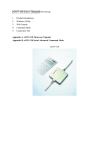
Aport-211 provides the easiest way to enable serial industrial device with
networking capability.
Product Specifications
Serial
Aport-211 converts the serial data to standard
TCP/IP protocol therefore the serial device can be accessed everywhere
RS-232/422/485: DB9 connector x1
via Internet or Ethernet. In addition, Aport-211 provides an embedded
RS-232 : RxD, TxD, RTS, CTS, DSR, DTR, DCD, GND
Web server which allows user to save the custom web page therefore user
RS-422: RX+, RX-, TX+, TX-, GND
can use a standard Web browser to remote manage the serial device.
RS-485: Data+, Data-, GND
Baud Rate: 300~38400 bps
Parity: None, Even, Odd
Package Check List
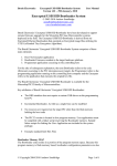
Aport-211 is shipped with following items:
Data Bits: 7, 8
1. Aport-211 Module
Stop Bits: 1, 2
2. Software CD and Electronic user manual
Flow Control: RTS/CTS, XON/XOFF
Protection: 15KV ESD
Digital Input/Output
General Purpose DIO x8
DIO0 to DIO5: Programmable Digital I/O (TTL)
DIO6 to DIO7: Programmable Digital I/O (CMOS)
Aport 211 User Manual
-3-
Aport 211 User Manual
-4-
Software
2
Protocol: TCP, UDP, IP, HTTP, ICMP, DHCP, Telnet
Getting Started
Utility: Java Configuration. Web Configuration, Serial Console,
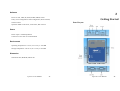
Panel Layout
Telnet Console
Operation Mode: TCP Server, TCP Client, Web Control
Power
Power input: 9~40VDC@100mA
Connector: Power Jack or Terminal Block
Environment
Operating Temperature: 0~55°C (32~131°F), 5~95% RH
Storage Temperature: -20~85°C (32~131°F), 5~95% RH
Dimension
108x78x25 mm (HxWxD) without ear
Aport 211 User Manual
-5-
Aport 211 User Manual
-6-
Connecting Power
Connecting 9~40VDC power line with the Aport 211 terminal
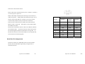
SW1 Setting:
block or the power jack. If the power is properly supplied, the
SW1 Key
Power LED will keep solid yellow color.
Connecting Ethernet Port
Connect a RJ45 Ethernet cable to the Ethernet port of Aport 211.
The Link/Activity light will keep solid yellow color if Ethernet
cable is corrected to the network and this light will keep flashing if
1
2
3
4
5
RS-232
ON
OFF
OFF
-
-
RS-422
OFF
OFF
OFF
-
-
RS-485
OFF
ON
ON
-
-
Normal
-
-
-
OFF
OFF
DHCP
OFF
ON
Default
ON
OFF
Console
ON
ON
there are data transmitted.
Normal: Aport is in Normal Operation Mode
Connecting Serial Port
DHCP: Network IP Address is assigned by DHCP Server
Use a null modem DB9 serial cable to connect a RS232 serial
device to Aport 211 serial port.
The null modem cable will cross
over the RxD to TxD connection between the serial device to
Aport 211.
Default: All the settings are reset to Factory Default.
Console: COM1 serial port is served as console port. User can
use ACSII command to configure Aport 211 via COM1 port.
Please refer to Appendix I for the ASCII command
All the settings will not be effective until system reboot
Switch SW1 Settings
by pressing RESET button
Set the SW1 setting to RS-232 mode and pin definition of Aport
211 serial port is as follow:
LED Status
The LED provides the Aport 211 operation information. The
Aport 211 User Manual
-7-
Aport 211 User Manual
-8-
LED status is described as follow:
Power LED: Power LED keeps ON if power (+9VDC to +40VDC)
is correctly input to Aport 211.
Ready LED: Ready LED keeps ON when Aport 211 firmware is
ready for operation.
Ready LED will be flash when Aport 211 in
Serial Console mode (SW1 key 4 and key 5 are ON) or Telnet
Pin
Number
Transmission Signals
RS-232
Console mode (Telnet Console port:5001 are connected)
4-wire
RS-485
RS485
Link/Act LED: Link and Activity LED will turn ON when the
1
DCD
TxD-
-
Ethernet cable is connected. When there is network data traffic,
2
RxD
TxD+
-
this LED will be flash.
3
TxD
RxD+
Data+
RX/TX LED: The RX/TX LED is a dual color LED that indicates
4
DTR
RxD-
Data-
the serial data traffic. In RS-232 mode, the Yellow LED stands
5
GND
GND
GND
for transmitting data and Green LED means receiving data.
In
6
DSR
-
-
RS-422/485 mode, the Yellow LED stands for receiving data and
7
RTS
-
-
Green LED means transmitting data.
8
CTS
-
-
9
-
-
-
Serial Port Pin Assignments
Serial Port COM1 uses a Male DB9 connector and it includes
RS-232, RS-422 and RS485 signal and pin assignments are
described as follow:
Aport 211 User Manual
-9-
Aport 211 User Manual
- 10 -
Digital I/O
Digital I/O uses DB9 connector and the pin assignments are described
Factory Default Settings
as follow:
If you forget your Aport 211 settings, you use SW1 to reset Aport
to factory default settings. The factory default settings are:
IP Address: 192.168.2.127
Data Port: 4000
Pin 5: DIO0
Telnet Port: 5001
Pin 4: DIO1
Web Port: 80
Pin 3: DIO2
Baud rate: 19200
Pin 2: DIO3
Data Format: N,8,1 ( Parity, Data bits, Stop bits)
Pin 1: DIO4
Flow Control: None
Pin 9: DIO5
Interface: RS-232
Pin 8: DIO6
Pin 7: DIO7
Pin 6: GND
DIO0 to DIO5 are TTL compatible Programmable DIO and DIO 6 to
DIO7 are CMOS compatible Programmable DIO. All the DIO
channel are internally pulled up to +5VDC with a 4.7K Ohm resistor.
Aport 211 User Manual
- 11 -
Aport 211 User Manual
- 12 -
3
Configure Aport 211
Java Configuration
Aport 211 provides four ways to configure the settings. They are:
1.
Java Configuration Utility
2.
Web Configuration Utility
3.
Serial Console
4.
Telnet Console
Install Java Configuration Utility
To install the Java Configuration Utility, you can simply copy
manager.jar to the desired folder. Double click on the icon will
To use the Java configuration utility software, you need to
start the manager.jar
install the Java 2 Platform, Standard Edition (J2SE) version
1.4.2 or later.
J2SE is free and available at
http://java.sun.com
Once this program started, it will perform a broadcast search to
find the Aport device in the network.
If you cannot find the
Aport module and you know the IP address of the module, you can
Aport 211 User Manual
- 13 -
click Search by IP item and specify the IP address to find the
Aport 211 User Manual
- 14 -
Aport 211.
The default IP address of Aport 211 is 192.168.2.127.
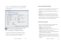
Serial and Data Packing Settings
Click on the row of the Aport setting, the configuration window
The group of setting is to configure the serial interface and data
will open as follow:
packing settings. Data Packing setting is are as follow:
Length: Pack the length of serial data before forwarding data to
Ethernet port
Timeout: the period of time to forward data to Ethernet Port
Delimiter: Wait for the Delimiter Character before forwarding
data to Ethernet port.
The Delimiters are maximum two bytes
Hex format ASCII code. If you use Carriage Return (CR) and Line
Feed (LF) as delimiters, you can specify 0D0A or 0d0a.
TCP/IP Network Settings
The group of TCP/IP Network settings are configuring the IP
Address, TCP port and operation mode as follow:
OpMode: TCP operation mode setting
When the SW1 is set to Console mode, Aport 211 cannot
TCP Port: TCP Port number of Aport 211
be discovered by the Configuration Utility and
Destination IP: The IP address of remote host which Aport 211
the configurations are controlled by serial console.
will actively connect to (TCP Client mode only)
Connect At: Startup means TCP connection is established when
When enter the configuration mode, the READY LED will be
system starts (TCP Client mode only)
flashing and TCP Data Port will be disabled and data transfer
Timeout: When this option is checked, TCP connection will be
between serial port and Ethernet port will be stopped.
disconnected if there is no serial data activity before timeout
IP Mode: Configure the IP Address to be Static IP or Dynamic IP
by DHCP
Aport 211 User Manual
- 15 -
Aport 211 User Manual
- 16 -
IP Address: Set the Static IP Address
Subnet Mask: Subnet Mask setting
Gateway: Gateway address setting
Device Name Settings
Click Edit Device Name button can edit the device name
Access Control Settings
Enable IP Filtering: When this option is checked, user can
Aport 211 provides IP address filtering method and password
specify the starting IP address and ended IP address which are
authentication for access control
allowed to access Aport 211 TCP port in order to prevent
unauthorized access.
Password Settings: Enter the new password will enable the
password authentication. Password is required to login Java
Configuration and Web configuration Pages in the next entry.
Aport 211 User Manual
- 17 -
Aport 211 User Manual
- 18 -
Save Configuration
The configuration is a text file and uses extension of txt. If you use
Text editor to open the configuration command, you will notice that
After the all the settings are configured, click to the Save to
the configuration file contains the ASCII command set of the
Module button to save the settings to the module. The new
configuration.
settings will be effective after the reboot of module by clicking the
editor to configure the settings and import it to the Aport 211 by
Reboot Module button. If the IP address had been modified,
using the Import button.
You can also edit these commands by the text
please do broadcast search or search by IP again to find the Aport
211 module.
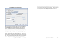
Save Configuration to File
You can also save current configuration to file by click the Save to
File button. A new window to specify the path of the file will pop
out as follow:
Aport 211 User Manual
- 19 -
Aport 211 User Manual
- 20 -
4
Web Configuration
Overview
Aport 211 can also be configured by Web Browser. The build-in
Web server and Web configuration pages makes Aport 211
configurable anywhere via a Web browser such as IE and Firefox.
To open the Web configuration pages, you can simply type the IP
address to the Web Address input such as 192.168.2.127. The
Login windows will ask you enter password if the password option
is enabled. After password confirmed, the web configuration
page will show up as follow:
The configuration is very similar to the Java configuration utility.
After completing the settings, click submit button then all the
settings will save to the module and the module will reboot
Aport 211 User Manual
- 21 -
automatically to use the new configuration.
Aport 211 User Manual
- 22 -
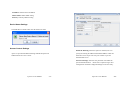
Before uploading the web page, please check if there is any anti virus
Customize Your Web Page
program which could prevent the tftp file transfer. Shut down the anti
virus program first to allow manager.jar upload the binary file.
After you complete your web page design, you can use the Manager
Utility (manager.jar) to upload the Web page to Aport 211 Web
server. The web files need to be converted to binary format first
before download to server. Place the web files in the source directory
and assign the output directory for the binary file. Pressing the
Convert button and you can find a binary file, fsdata.anf has been
created. Use this binary file to upload to Web server. You can see
the converted file is available in the Upload binary file to device dialog
box. Press Upload and the Web Page Binary files will be uploaded to
server.
Manager Utility uses tftp protocol to upload web page.
Aport 211 User Manual
- 23 -
Aport 211 User Manual
- 24 -
5
Serial/Telnet Command
Flow Control: None
Interface: RS-232
Now you can use serial terminal software to send the ASCII
command to Aport 211.
In Serial Console Mode, all the network functions will be
Overview
disabled
Aport 211 provides a set of ASCII command to configure Aport
Once the configuration is completed, remember to switch SW1
through a serial and Ethernet port.
back to Normal operation mode and reboot the module by Reset
User can use serial terminal or
Telnet command to configure Aport 211 when Web browser and
Command or push reset button.
Java utility are available. In addition, these functions provide
user the most convenient way to develop their own configuration
Telnet Console Mode
utility software simply to use the ASCII command.
Aport 211 uses Port number 5001 as telnet console port.
Serial Console Mode
Remember to turn on the LOCALECHO before opening the telnet
To enter the Serial console mode, you can switch SW1 (4~5) to
console port. You must login first before sending command to
ON position and then serial port will function as a console port.
Aport 211. If password is enabled, you need to use the password
The READY LED will keep flash that indicates Aport is in serial
to log in. The password is encrypted using Tiny Encryption
console mode. Please set the serial data setting of the Serial
Algorithm (TEA) and the keys are sixteen bytes with low case
Terminal software (such as Hyper Terminal) to be the same as the
character from “a” to “p”. The login command format is as
Aport 211 serial port. If you forgot the serial port setting, you
follow:
$LOG[16 bytes of TEA Encrypted Password]
can use SW1 to reset it to factory default setting as use following
or
setting:
$LOG
Baud rate: 19200
Data Format: N,8,1 ( Parity, Data bits, Stop bits)
Aport 211 User Manual
- 25 -
if there are no password settings
Aport 211 User Manual
- 26 -
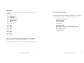
Forgot Password
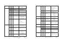
Command
If you forgot the Password, you can switch SW1 to Factory Default
setting mode and use default IP Address 192.168.2.127 and enter the
R
Category
Basic
Web console pages. Once the configuration is completed,
G
S
G
remember to switch SW1 back to Normal operation mode and
S
reboot the module by Reset Command or push reset button.
Password is not required for serial console mode.
W
Serial
G
Parameters
(2 bytes)
(command related)
BN: Device Name
Max. 14 bytes
BM: Model Name
Default
BP: Password
BV: Firmware ver...
G
Therefore you
Function
S
SB: Baud Rate
can also use serial console to reset the password.
Max. 8 bytes
Default
1200
2400
4800
9600
Command Syntax
19200
38400
The command syntax is
G
S
[Delimiter][Command][Carriage Return/CR][Line Feed/LF]
SD: Data Format
N72
(Parity,Data,Stop)
E71
Delimiter (one byte): The command begins with a delimiter of
O71
dollar sign $ and if Aport 211 receives the correct command it will
N81
response with an echo which begins with the delimiter of a
E72
percentage sign %.
O72
Command: The command are ASCII string which contains three
E81
elements: {Read/Write}{Function}{Parameter} as described as
O81
follow:
N82
G
S
SF: Flow Control
NONE
RTS/CTS
XON/XOFF
G
Aport 211 User Manual
- 27 -
S
SI: Interface
Aport 211 User Manual
RS-232
- 28 -
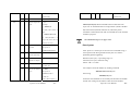
Network
RS-422
[1]: Timeout Option
RS-485
[2]: Length Option
G
S
LI: IP Address
e.g. $SLI192.168.2.127
}={1:Enable,0:Disable}
G
S
LN: Netmask
e.g.$SLN255.0.0.0
e.g. $SOD110
G
S
LG: Gateway
e.g. $SLG192.168.2.254
G
S
LC: IP Mode
G
S
OS: Delimiter
e.g. $SOS0D0A (CR/LF)
0: Static IP
G
1: DCHP
G
LM: MAC
Default
G
LS: LAN Status
Link fail
Max. two bytes characters
S
OT: Timeout
0~65535
(unit: ms)
e.g.$SOT500
G
Link OK,100M
S
OL: Data Length
0~1024
e.g.$SOL20
Link OK, 10M
G
S
LW: TCP windows
0:128, 1:256, 2:512,
size
3:1024
Access
G
S
OM:
Operation
Mode
G
S
OC: TCP connection
timeout option
G
S
S
OF:IP Filtering
1:Enable
G
S
OI: Authorized IP
168.2.180 (Starting IP:Ended
128 bytes
IP)
TS:TCP Server
TCP Server
G
S
VP: Listen Port
TCP Client
G
S
CI: Destination IP
e.g.$SCI192.168.1.211
TO: Disconnect if
G
S
CP: Destination Port
e.g.$SCP4001
timeout
G
S
CC: Connection
0: Reserved for PPPoE
Logic
1:Establish connection when
AC: always connect
OU: Timeout clock
OD: Data Packing
1~65535
e.g. $SVP4000
TC:TCP Client
0~65535
Serial Data in
e.g. $SOU500
S
e.g.$SOI192.168.2.127:192.
means TCP window size
(unit: ms)
G
0: Disable
Control
e.g. $SLW0
Operation
G
System
S
YC: System mode
R: Reboot system
Three parameters:{
F: Reset to default setting
[0]:Delimiter Option
and reboot
Aport 211 User Manual
- 29 -
Aport 211 User Manual
- 30 -
DIO
D: Set current setting as
e.g. $GDI:4
Default setting
Get DIO4 status
Remark: Italic font stands for Command String
S
EI: Exit console
S
DM: Set Digital I/O
I: Input
mode
O: Output
CR/LF (two bytes): Both command from host and echo from
e.g. $SDMI:0,4,5
Aport 211 are terminated with a Carriage Return (ACSII code Hex
set DIO0, DIO4, DIO5 as
0d) and Line Feed (ASCII code Hex 0a). Therefore please
input
remember to add CR/LF at the end of command line in the terminal
emulation program.
$SDMO:1:H,2:L,3:H
set
DIO1,DIO2,DIO3
as
output and initial state are
All command strings are in Upper Case
High (H) or Low (L)
DM:
G
Get
Digital
I/O mode
S
DOH:
Echo Syntax
e.g. $GDM
the response is
Set
DO
%GDM I,O,O,O,I,I,O,O
After Aport 211 console port received correct command string, it
e.g. $SDOH:1,3,7
will response Echo String and the Echo Syntax is as follow:
[Delimiter][Function][Status]
channel High Output
S
DOL:
Set
DO
Delimiter (One byte): A percentage sign “%”
e.g. $SDOL:2,6
Function (Two bytes): function string
channel Low Output
G
DO:X
Status: “OK” or “FAIL”
e.g. $GDO:2
get DIO2 status
G
DI: Get DI channel
e.g. $GDI
status
the response is
For example: Set the IP Address by sending command
$SLI192.168.2.125(CR)(LF)
%GDI 0=1,4=0,5=1
%SLIOK(CR)(LF)
It stands for
DIO0=1,DIO4=0,DIO5=1
Aport 211 User Manual
Echo string
- 31 -
means the new IP address is successfully transferred to the module
and the new setting will be effective after reboot the module.
Aport 211 User Manual
- 32 -
To get IP address setting, you can send a command as follow
$GLI
Appendix A
then the Echo string will be
%GLI192.168.2.125
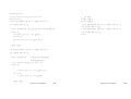
Tiny Encryption Algorithm
Always remember to reboot the module by send command
1.
Example of TEA.C
$SYCR to use the new configuration
/************************************************
The Tiny Encryption Algorithm (TEA) by David Wheeler and Roger Needham of the
Cambridge Computer Laboratory. Placed in the Public Domain by
David Wheeler and Roger Needham.
**** ANSI C VERSION (New Variant) ****
Notes:TEA is a Feistel cipher with XOR and addition as the non-linear mixing
functions.
Takes 64 bits of data in v[0] and v[1]. Returns 64 bits of data in w[0] and w[1].
Takes 128 bits of key in k[0] - k[3].
TEA can be operated in any of the modes of DES. Cipher Block Chaining is, for
example, simple to implement. n is the number of iterations. 32 is ample,
16 is sufficient, as few as eight may be OK. The algorithm achieves good
dispersion after six iterations. The iteration count can be made variable if
required.
Note this is optimised for 32-bit CPUs with fast shift capabilities. It can very
easily be ported to assembly language on most CPUs. delta is chosen to be the
real part of (the golden ratio Sqrt(5/4) - 1/2 ~ 0.618034 multiplied by 2^32).
This version has been amended to foil two weaknesses identified by David A.
Wagner ([email protected]): 1) effective key length of old-variant TEA was
126 not 128 bits 2) a related key attack was possible
Aport 211 User Manual
- 33 -
Aport 211 User Manual
- 34 -
although impractical.
}
************************************************/
2.
//#include "xtea.h"
#ifndef __XTEA_H__
void encipher(unsigned long *const v,unsigned long *const w,
#define __XTEA_H__
const unsigned long *const k)
void encipher(unsigned long *const v,unsigned long *const w,
{
const unsigned long *const k);
register unsigned long
y=v[0],z=v[1],sum=0,delta=0x9E3779B9,n=32;
while(n-->0)
The TEA.H
void decipher(unsigned long *const v,unsigned long *const w,
const unsigned long *const k);
{ y+= (z<<4 ^ z>>5) + z ^ sum + k[sum&3];
#endif
sum += delta;
z+= (y<<4 ^ y>>5) + y ^ sum + k[sum>>11 & 3];
}
w[0]=y; w[1]=z;
}
void decipher(unsigned long *const v,unsigned long *const w,
const unsigned long *const k)
{
register unsigned long
y=v[0],z=v[1],sum=0xC6EF3720,
delta=0x9E3779B9,n=32;
/* sum = delta<<5, in general sum = delta * n */
while(n-->0)
{
z-= (y<<4 ^ y>>5) + y ^ sum + k[sum>>11 & 3];
sum -= delta;
y-= (z<<4 ^ z>>5) + z ^ sum + k[sum&3];
}
w[0]=y; w[1]=z;
Aport 211 User Manual
- 35 -
Aport 211 User Manual
- 36 -