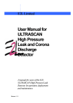
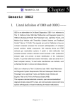
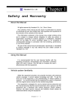
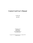
1
Hanatech Co., Ltd.
Chapter 4
ULTRASCAN P1 Functions
The functions you can choose when all the test vehicle details are selected
properly are explained in this chapter of the manual.
The actual list of
available functions may be different according to the vehicle you want to test.
I.
Diagnostic Trouble Code---------------------
A. DTC Read
1. Pulse signal type
a. Many of old Toyota, Honda, Mazda, Hyundai and Kia cars until early 90’s
support slow pulse signal output for the DTC reading function.
As shown below, ULTRASCAN P1 shows the pulse signal being received
through the DLC adapter in the top and the received DTC numbers.
b. Manual input
-
Even older cars such as Honda with 2-pin adapter have no signal
output terminal for DTC in the DLC adapter.
In this case,
ULTRASCAN P1 shows the following message as there is no signal
Chapter 4 - 1
USER MANUAL
For ULTRASCAN P1
input through the adapter.
-
You have to count the MIL flashing on the dashboard and manually
input the DTC number to ULTRASCAN P1 to view the details as
below:
-
Long flash signals count for tens and short signals for ones. Input
two digits for tens and ones in sequence using the numeric keypad.
A flash signal for a code is followed by another if there are multiple
trouble codes.
Blinking signals for all trouble codes flash in
sequence, and repeat after a pause.
Chapter 4 - 2
Hanatech Co., Ltd.
c.
Chapter 4
Others
-
Generally ULTRASCAN P1 reads DTC pulse signal from the
diagnostic adapter and shows the DTC number, title and details
automatically.
2. Serial Communication type
a. Most of the cars built in 1990’s or later support serial communication with
a scanner, and the DTC is read by bi-directional communication.
b. ULTRASCAN P1 sends a command to the control module to reply with
the DTC numbers stored in memory, and the control module replies
thereupon.
Chapter 4 - 3
USER MANUAL
For ULTRASCAN P1
B. DTC Erase (Clear fault code)
1. Pulse signal type
a. Pulse signal type does not support bi-directional serial communication,
therefore, a scanner is unable to send a command to the control module
to erase the DTC information from memory.
These old cars require you to remove battery terminal to clean up
diagnostic information from control module memory.
Removing the battery terminal will get rid of all information contained in
the car stereo and other electronic devices. And it may not effectively
erase the fault codes in some cars. Refer to the original repair manual
for further information.
Check if DTC information is properly removed by reading the trouble
code again after erasing the code.
2. Serial communication type
a. ULTRASCAN P1 sends a command to the control module to erase DTC
information stored in memory, and the control module replies thereupon.
b. Check if DTC information is properly removed by reading the trouble
code again after erasing the code
Chapter 4 - 4
Hanatech Co., Ltd.
Chapter 4
C. DTC Help tips
a. Help tips are provided when you press the [HELP] key after locating the
highlighted bar on one of the detected trouble code(s). This function is
available when ULTRASCAN P1 detects one or more trouble code(s)
b. Help tips including trouble code definition, conditions and check points
are provided for all Korean cars and Malaysian cars. Wiring diagrams
are also provided for Korean cars of 2000 model-year or older.
c.
Press the [ESC] key to return to DTC list.
Chapter 4 - 5
USER MANUAL
For ULTRASCAN P1
II. Current Data ----------------------------------(= Data Stream, Live Data, Service Data)
A. Pulse Signal Type
a.
Data stream is not generally supported for this type of old cars because the
speed of pulse signal communication is too slow to read the data stream
variables.
b.
Some of old Toyota cars using 17-pin rectangular adapter exceptionally
support data readings as the system supports relatively high speed pulse
signal communication.
B. Serial Communication Type
a.
Most of control systems with serial communication support data stream
function.
b.
Select [Current data] from the menu, then the data readings follow.
Some systems like SRS or ABS may be designed not to support data stream
intentionally by the car make while the other systems are supported.
A
scanner is a passive tool that reads information from the control system, and
it is unable to actively generate information that the system does not provide.
Chapter 4 - 6
Hanatech Co., Ltd.
Chapter 4
C. Data Freeze
The [Data Freeze] function places the selected data stream variable on top of
the LCD screen so that the user can check and compare desired sensor
values continually without having to scroll up and down.
This function is different from ‘Freeze Frame Data’ function of Generic OBD2.
1)
Step One
Select a desired sensor using the [◀][▶] and the [▲][▼] keys.
2)
Step Two
Press the [ENTER] key to freeze the selected sensor.
i.e., when O2 sensor and MAP sensor are selected and frozen, these
sensor values will be placed at the top of the display as below :
3)
Step Three
Up to five sensors may be frozen at a time.
For example, if the Injection
Time, which can be shown when scrolled down, is selected and frozen,
Injection Time value will be placed below the previously frozen O2 and MAP
sensor.
Chapter 4 - 7
USER MANUAL
For ULTRASCAN P1
D. Data Graph
ULTRASCAN P1 provides the [Data Graph] function for more efficient
data analysis.
a
When you press the [1] key after locating the highlight bar on the desired
sensor, the sensor data graph will be displayed as shown below.
b
You can display up to 3 graphs in a screen by choosing the sensors as
previously explained [Data Freeze] procedure - Press the [Enter] key
after locating the highlight bar on the desired sensor, and then press the
[1] key. When more than 4 sensors are selected, the graphs of upper
three sensors will be displayed.
Chapter 4 - 8
Hanatech Co., Ltd.
c
Chapter 4
For each sensor data graph, the name of the sensor and its current
value will be simultaneously displayed together.
d
To change the sensor, go back to the previous Service Data display by
pressing the [Esc] key, and then choose other sensors.
e
To halt the graph output, press the [ENTER] key.
you press the [ENTER] key again.
Chapter 4 - 9
It will resume when
USER MANUAL
For ULTRASCAN P1
E. Help tips
a
When you press the [HELP] key after locating the highlight bar on a
certain data stream variable, the help message will be displayed.
This
works the same for detected Trouble Codes in [Self Diagnosis] function.
b
Detailed information including conditional standard range on the selected
sensor will be displayed as shown below.
c
Press the [ESC] key to go back to the data stream display.
Chapter 4 - 10
Hanatech Co., Ltd.
Chapter 4
III. Actuation Test ---------------------------------
The actuation test is a very helpful function that temporarily activates
or stops a certain actuator such as an injector, a motor or a solenoid
by force, so that the user can evaluate the system's condition or the
part’s normal operation by observing its reaction
-
Signals from various sensors are input to a control unit, and the
actions are taken by controlling to actuators.
Sensors and
actuators are causes and effects in a control system.
-
While the data stream function is useful to observe if the sensors are
working properly and the control unit is collecting correct data from
the sensors without problem, the actuator test is helpful to examine if
the actuators are working in normal conditions and the control unit is
commanding proper control over the system.
-
Some of the cars such as Nissan or Toyota provide even more
advanced actuation tests by letting the user observe the reaction of
overall control system when manually adjusting the sensor input
values.
Chapter 4 - 11
USER MANUAL
For ULTRASCAN P1
A. Menu Selection
a
Choose [ACTUATION TEST] from the function Selection Menu
b
The name of the actuator to be tested, test method and the test condition
are shown in the display.
Available actuators, test methods and
conditions may differ in each vehicle.
B. Test Start
1. Selecting Test Item
a
Choose an actuator to test from the menu by using the [▲] and [▼] keys.
b
Check the test conditions and press the [ENTER] key when all the
conditions are met.
2. Testing
a
[TESTING...] message will be displayed during the actuation test
Test method means how the actuation test will be performed.
the actual reaction of the actuator
Chapter 4 - 12
Check
Hanatech Co., Ltd.
b
Chapter 4
In the example below, the injector will stop injecting fuel for 6 seconds
while engine is idling, and it will make engine stall or unstable.
c
Testing a fan or an injector is easy to check the proper reaction as it
generates distinctive changes in vehicle condition such as fan whining or
unstable idling.
However, valves or motors are generally tested while
engine is stopped and all you can hear may be a small and unclear
electric buzzing sound.
Test in a quite place and observe the test
results carefully.
d
When the test is completed, the [TEST COMPLETE] message will be
displayed. You can choose other actuators by using the [▲] and [▼]
keys. Press the [ESC] key to quit test mode.
Chapter 4 - 13
USER MANUAL
For ULTRASCAN P1
IV. Black Box -------------------------------------(= Record Replay)
Just like the 'Black Box' or a ‘flight recorder’ of an aircraft, ULTRASCAN
P1 can 'record' data stream during the vehicle drive test and the recorded
data can be 'retrieved' later for intensive analysis of vehicle's condition.
ULTRASCAN P1
has a menu, so called “Record Replay” same as Black
Box function and you can understand “Record Replay” as Black Box function.
A. Function selection
Choose [#. Black Box Data] from the [Function Selection Menu] after
selecting Origin, Car Manufacturer, Model name and system to test.
Chapter 4 - 14
Hanatech Co., Ltd.
Chapter 4
B. Capacity
a
During a normal test, the [Data Stream] frames pass by in rapid
succession, and cannot be recalled unless the data has been saved.
Thanks to its extensive internal memory, ULTRASCAN P1 can record up
to 2040 frames of Data Stream for multiple cars.
b
By loading the recorded data, you can diagnose sensor data frame to
frame without missing a single critical moment.
C. Memory Check
a. ULTRASCAN P1 checks its internal memory before it starts recording
Black Box data. If there is no sufficient free memory space available,
ULTRASCAN P1 will suggest deleting one or more of previous record(s).
b. Press the [ERASE] key to proceed, then a list of saved data will follow.
Locate the highlight bar on data to delete, and press the [ENTER] key.
A query for your confirmation will follow.
otherwise press the [NO] key.
Chapter 4 - 15
Press the [YES] key to erase
USER MANUAL
For ULTRASCAN P1
D. PID(Live data parameter) selection
a
You are required to select the parameters to record.
b
ULTRASCAN P1 will show you the whole live data parameters available
in the control system you selected.
Locate the highlight bar on the
desired parameter and press the [ENTER] key.
Selected parameter will be marked star(*).
You can also deselect the parameter by repeating the procedure.
c You can select up to 40 PIDs to record.
Press the [ESC] key when the
selection is completed, then ULTRASCAN P1 will start recording data.
Chapter 4 - 16
Hanatech Co., Ltd.
Chapter 4
E. Trigger Modes
There are three trigger modes in the black box function.
a
Continuous Record Mode (No trigger mode)
-
ULTRASCAN P1 will record live data of selected parameters up to
2040 frames or until you press the [ESC] key.
-
Percentile memory usage and sampling time(frequency) will appear
in the center of the screen while recording data, and the actual live
data values will remain unchanged.
-
Since no DTC trigger is applied in this mode, number of “Before
DTC” frames will remain 0, and the “After DTC” will keep increasing
as the more frames are recorded.
Chapter 4 - 17
USER MANUAL
b
For ULTRASCAN P1
Automatic Trigger Mode (Triggered by DTC)
-
ULTRASCAN P1 will keep recording live data of selected
parameters up to 128 frames.
-
Once a DTC is detected or the [ESC] key is pressed by the user, it
will proceed with recording remaining frames up to 2,040 or until you
abort.
-
This function will let you have a set of data stream before and after
the ECM’s DTC recognition when you perform the test drive.
-
Before DTC, you will see the Live Data of the selected parameters
keep refreshing, however, once triggered by DTC or [ESC] key
stroke, only the percentile process information and sampling
frequency will be displayed.
Chapter 4 - 18
Hanatech Co., Ltd.
c
Chapter 4
Manual Trigger Mode
-
ULTRASCAN P1 will keep recording live data of selected
parameters up to 128 frames, and once the [ESC] key is pressed by
the user, it will proceed with recording remaining frames up to 2040.
-
The screen display is the same as when selecting the Auto Trigger
Mode.
Chapter 4 - 19
USER MANUAL
For ULTRASCAN P1
F. Saving the recorded data
a
When the total frame number reaches 2040 or when you press the
[ESC] key to abort, a query asking you if you would like to save recorded
data or to discard it.
b
Press [YES] to save or [NO] to cancel.
When pressed [YES], a dialog box follows and asks you to input the test
date.
Enter the date and press the [ENTER] key to save the recorded
data to ULTRASCAN P1 memory.
Pressing the [ESC] key cancels saving data.
Date format is DD-MM-YYYY(D-day, M-month, Y-year), and only
numeric values are available.
c
Tested Vehicle model name and control system will be saved as well as
the date stamp for future retrieval.
Chapter 4 - 20
Hanatech Co., Ltd.
Chapter 4
G. Black Box Data Load
a
You can load saved data by choosing [BLACKBOX RECORD LOAD /
ERASE] from the [Car Manufacturer Selection] menu as shown below:
b
A list of recorded Black Box Data will follow for your selection
Up to 4 black box data can be stored in the memory per car
manufacturer, therefore, up to 4 saved black box data can be listed in
the menu.
c
The details of recorded data will be displayed for confirmation.
record is correct, press the [ENTER] key.
d
If the
Press the [ESC] key to abort.
If you want to erase any of these saved data, locate the highlight bar and
press the erase key.
Chapter 4 - 21
USER MANUAL
For ULTRASCAN P1
H. Loaded Blackbox data
Loaded black box data has basically the same format as the [Service
Data (Live Data Stream)].
See the illustration below.
1. Data format
In the lower part of the display, the total number of recorded frames, frame
number before and after the DTC(Diagnostic Trouble Code), and the number
of DTC detected is displayed.
In the example below, you can see that a
total of 458 frames were recorded, and data stream currently shown in the
main window is of the 336th frame from the beginning.
It also tells you that
the current frame is the 80th after 2 trouble codes were detected.
The live data values may not be realistic as the screen was
captured while the scan tool was linked to a simulator.
2. Data Replay
a. Press the [YES] key then the saved blackbox data will start
replaying. ULTRASCAN P1 preserves the refresh time intervals of
Black Box data.
Therefore, Black Box data is replayed at the same
speed as when it was originally recorded.
Chapter 4 - 22
Hanatech Co., Ltd.
Chapter 4
b. If you want to go forward or backward faster, press the [◀] or [▶]
key while replaying.
Replay speed will restore to the original speed
when the key is released.
c.
Pressing the [YES] key will pause the replay.
You can resume
replaying from the frame where it was paused by pressing the [YES]
key again.
d. Pressing the [NO] key will stop replaying. You can restart replay
by pressing the [YES] key again, but it will start from the first frame.
Chapter 4 - 23
USER MANUAL
For ULTRASCAN P1
3. Graph
a
As previously explained in section [3. Service Data], data from up to
three selected parameter data can be graphed.
b
Make sure that the Black Box data replay is stopped.
If it is being
replayed or paused, press the [NO] key to stop replaying completely.
c
Choose the parameter by locating the highlight bar and pressing the
[ENTER] key.
The selected parameter will be marked with a triangle as
shown below:
d
Then press the [1] key to view the data in graph format.
The line graphs are flat as it is not based on
data recorded from the active vehicle.
Chapter 4 - 24
Hanatech Co., Ltd.
e
Chapter 4
Up to 316 frames can be displayed on a single page.
If recorded data has more than 316 frames, you can shift to next or
previous page by using the [▲] and [▼] keys.
f
The dotted line indicates from which frame the live data parameter
values are being displayed.
You can move it left and right with the [◀]
and [▶] keys.
g
Elapsed time and frame number are indicated in the bottom.
-
Continuous Record (No trigger) Mode: Elapsed time and number of
frames from the first frame
-
Automatic / Manual Trigger (Triggered by DTC or user) Mode:
Elapsed time and number of frames from the trigger point (DTC
detection or [ESC] key stroke by the user).
Before the trigger point
will be marked in negative values.
h
To return to the Black Box Data Display, press the [ESC] key.
Chapter 4 - 25
USER MANUAL
For ULTRASCAN P1
4. DTC
a
You can check the DTC(s) found during recording Black Box Data.
b
Make sure that the Black Box data replay is stopped.
If it is being
replayed or paused, press the [NO] key to stop replaying completely.
c
Press the [2] key then the list of DTC(s) will appear as below:
d
Because Black Box Data is not live or active, you cannot erase DTC(s).
Chapter 4 - 26
Chapter 4
Hanatech Co., Ltd.
V. Connector Location --------------------------a
The vehicle side OBD2 adapter is easy to find as the location is quite
regular – under the dash, however, the old vehicle side DLC adapters of
OBD generation 1 are located quite randomly and sometimes it is very
difficult to find.
ULTRASCAN P1 has the vehicle side adapter location maps for some
car make to aid the user in locating the adapters. The locations
suggested in this function are purely from Hanatech’s experience,
therefore, it may contain incorrect information.
It is always highly
recommended to refer to the original repair manual published by the car
manufacturers for correct information and there are some makes which
does not have adapter location map for the reason of on going S/W
enhancement.
b
Select [CONNECTOR LOCATION] from the vehicle selection menu if the
adapter is not found in the place where it is supposed to be.
A drawing indicating the location of the vehicle side adapter follows.
In
the right bottom of the display, the total number of location maps for the
selected car make is indicated.
The example below is when Hyundai
motors is selected, and it tells there are total 5 maps.
Chapter 4 - 27
USER MANUAL
c
For ULTRASCAN P1
The maps are provided in the order of most frequently found location.
Press Up or Down key to view the next or previous map. Press the
[ESC] key to return to vehicle selection menu.
d
Location maps for Korean cars are based on Left Hand Drive vehicles,
and the others such as Japanese, Australian and Malaysian cars are
based on Right Hand Drive cars.
You may have to consider reversed
image according to your local practice.
Refer to each car make section in this manual for further information.
Chapter 4 - 28
Hanatech Co., Ltd.
Chapter 4
VI. Immobilizer -----------------------------------a. ULTRASCAN P1 provides diagnostic functions on Immobilizer systems.
The function includes Key Coding as well as DTC Read/Erase or Live
Data functions in some car makes such as Hyundai, Kia, Australian
Holden, Australian Ford and Mitsubishi, and such OEM level functionality
is expected to be extended to the other car makes as further
development is carried out..
b. Immobilizer system is case sensitive because it is directly related with
the security issues. Misuse or improper operation of the this key coding
or programming function may result in break down of the system and
immobilize the vehicle, which generates greater loss of money and time
for restoration.
Hanatech recommends this function to be used only by the trained and
authorized technicians with thorough understanding of the whole
procedure, for lawful repair purposes only.
The user is fully responsible for any loss, damage, immobilizer
systems failure or lock down caused by misuse or improper
operation due to lack of operator knowledge or instructional
material
c.
If you select any key copying,
coding, reset or programming
function from an immobilizer
system
function
menu,
a
disclaimer will appear on the
screen asking to read the
warning message as shown
below:
Chapter 4 - 29
USER MANUAL
For ULTRASCAN P1
Read the whole disclaimer by using the [up] / [down] arrow keys, and
type in the last 4 digits of the serial number in the bottom of the screen
and then press the [YES] key to proceed to the next step.
Pressing the [NO] key will abort the function.
The serial number is found in the back of the base unit behind the grip
belt.
You cannot type in the numbers unless you scroll the whole
disclaimer down to the last line.
Chapter 4 - 30