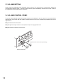
1
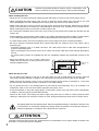
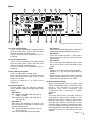
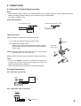
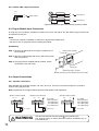
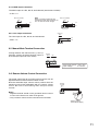
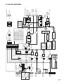
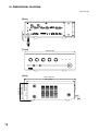
OPERATING INSTRUCTIONS
MIXER AMPLIFIERS
BG-2035
BG-2060
BG-2120
TABLE OF CONTENTS
1. IMPORTANT SAFETY INSTRUCTIONS .... 2
7.2. Automatic Mute .................................. 13
2. SAFETY PRECAUTIONS ........................... 3
8. MOH OUTPUT ASSIGNMENT ................. 13
3. GENERAL DESCRIPTION ......................... 5
9. 2-CHANNEL BROADCAST ...................... 14
4. FEATURES ................................................. 5
10. OPERATION ............................................. 15
5. NOMENCLATURE AND FUNCTIONS
Front ............................................................ 6
Rear ............................................................. 7
11. INSTALLATION PRECAUTIONS ............. 15
6. CONNECTIONS
6.1. Removable Terminal Plug
Connection ........................................... 9
6.2. Input Connections ................................ 9
6.3. Plug-In Module Input Connection ....... 10
6.4. Output Connections ............................ 10
6.5. Manual Mute Terminal Connection .... 11
6.6. Remote Volume Control Connection .. 11
12. RACK MOUNTING BRACKET
ATTACHMENT ......................................... 15
13. VOLUME SETTING .................................. 16
14. VOLUME CONTROL COVER .................. 16
15. BLOCK DIAGRAM ................................... 17
16. DIMENSIONAL DIAGRAM ....................... 18
17. SPECIFICATIONS .................................... 19
Accessories ............................................... 20
Optional Product ........................................ 20
7. MUTING FUNCTION
7.1. Manual Mute ....................................... 12
Thank you for purchasing TOA's Mixer Amplifier.
Please carefully follow the instructions in this manual to ensure long, trouble-free use of your equipment.
1. IMPORTANT SAFETY INSTRUCTIONS
• Read these instructions.
• Keep these instructions.
• Heed all warnings.
• Follow all instructions.
• Do not use this apparatus near water.
• Clean only with dry cloth.
• Do not block any ventilation openings. Install in accordance with the manufacturer's instructions.
• Do not install near any heat sources such as radiators, heat registers, stoves, or other apparatus (including
amplifiers) that produce heat.
• Do not defeat the safety purpose of the polarized or grounding-type plug. A polarized plug has two blades
with one wider than the other. A grounding type plug has two blades and a third grounding prong. The wide
blade or the third prong are provided for your safety. If the provided plug does not fit into your outlet, consult
an electrician for replacement of the obsolete outlet.
• Protect the power cord from being walked on or pinched particularly at plugs, convenience receptacles, and
the point where they exit from the apparatus.
• Only use attachments/accessories specified by the manufacturer.
• Use only with the cart, stand, tripod, bracket, or table specified by the manufacturer, or sold with the
apparatus. When a cart is used, use caution when moving the cart/apparatus combination to avoid injury
from tip-over.
• Unplug this apparatus during lightning storms or when unused for long periods of time.
• Refer all servicing to qualified service personnel. Servicing is required when the apparatus has been
damaged in any way, such as power-supply cord or plug is damaged, liquid has been spilled or objects have
fallen into the apparatus, the apparatus has been exposed to rain or moisture, does not operate normally, or
has been dropped.
2
2. SAFETY PRECAUTIONS
• Before installation or use, be sure to carefully read all the instructions in this section for correct and safe
operation.
• Be sure to follow all the precautionary instructions in this section, which contain important warnings and/or
cautions regarding safety.
• After reading, keep this manual handy for future reference.
Safety Symbol and Message Conventions
Safety symbols and messages described below are used in this manual to prevent bodily injury and property
damage which could result from mishandling. Before operating your product, read this manual first and
understand the safety symbols and messages so you are thoroughly aware of the potential safety hazards.
The exclamation point within an equilateral triangle is intended to alert the user to the presence of
important operation and maintenance (servicing) instruction in the literature accompanying the
appliance.
WARNING
Indicates a potentially hazardous situation which, if mishandled, could
result in death or serious personal injury.
When Installing the Unit
• Do not expose the unit to rain or an environment where it may be splashed by water or other liquids, as
doing so may result in fire or electric shock.
• Use the unit only with the voltage specified on the unit. Using a voltage higher than that which is specified
may result in fire or electric shock.
• Do not cut, kink, otherwise damage nor modify the power supply cord. In addition, avoid using the power
cord in close proximity to heaters, and never place heavy objects -- including the unit itself -- on the power
cord, as doing so may result in fire or electric shock.
• Avoid installing or mounting the unit in unstable locations, such as on a rickety table or a slanted surface.
Doing so may result in the unit falling down and causing personal injury and/or property damage.
• External wiring connected to the terminals marked with
requires installation by an instructed person.
• The apparatus shall be connected to a mains socket outlet with a protective earthing connection.
• The socket-outlet shall be installed near the equipment and the plug (disconnecting device) shall be easily
accessible.
• Use the optional Rack mounting bracket MB-1000 when mounting the unit(s) in an equipment rack. Remove
four M4 x 8 screws on both sides of the unit, and mount the bracket there using the M4 x 16 screws
(supplied with the bracket) instead.
When the Unit is in Use
• Should the following irregularity be found during use, immediately switch off the power, disconnect the power
supply plug from the AC outlet and contact your nearest TOA dealer. Make no further attempt to operate the
unit in this condition as this may cause fire or electric shock.
· If you detect smoke or a strange smell coming from the unit
· If water or any metallic object gets into the unit
· If the unit falls, or the unit case breaks
· If the power supply cord is damaged (exposure of the core, disconnection, etc.)
· If it is malfunctioning (no tone sounds.)
• To prevent a fire or electric shock, never open nor remove the unit case as there are high voltage
components inside the unit. Refer all servicing to your nearest TOA dealer.
• Do not place cups, bowls, or other containers of liquid or metallic objects on top of the unit. If they
accidentally spill into the unit, this may cause a fire or electric shock.
• Do not insert nor drop metallic objects or flammable materials in the ventilation slots of the unit's cover, as
this may result in fire or electric shock.
3
CAUTION
Indicates a potentially hazardous situation which, if mishandled, could
result in moderate or minor personal injury, and/or property damage.
When Installing the Unit
• Never plug in nor remove the power supply plug with wet hands, as doing so may cause electric shock.
• When unplugging the power supply cord, be sure to grasp the power supply plug; never pull on the cord
itself. Operating the unit with a damaged power supply cord may cause a fire or electric shock.
• When moving the unit, be sure to remove its power supply cord from the wall outlet. Moving the unit with the
power cord connected to the outlet may cause damage to the power cord, resulting in fire or electric shock.
When removing the power cord, be sure to hold its plug to pull.
• Do not block the ventilation slots in the unit's cover. Doing so may cause heat to build up inside the unit and
result in fire.
• Avoid installing the unit in humid or dusty locations, in locations exposed to the direct sunlight, near the heaters,
or in locations generating sooty smoke or steam as doing otherwise may result in fire or electric shock.
• To avoid electric shocks, be sure to unplug the unit's power supply cord when connecting speakers.
• Be sure to follow the instructions below when rack-mounting the unit. Failure to do so may cause a fire or
personal injury.
· Install the equipment rack on a stable, hard floor. Fix it with anchor bolts or take other arrangements to
prevent it from falling down.
· When connecting the unit's power cord to an AC outlet, use the AC outlet with current capacity allowable to
the unit.
· No rack-mounting screws are supplied with the unit. Separately prepare the appropriate screws for the
rack.
• Keep the amplifier over 10 cm (3.94") away from
objects that may obstruct air flow to prevent the unit's
internal temperature rise.
When the Unit is in Use
Over 10 cm
(3.94")
Over 10 cm (3.94")
Over 10 cm (3.94")
• Do not place heavy objects on the unit as this may cause it to fall or break which may result in personal
injury and/or property damage. In addition, the object itself may fall off and cause injury and/or damage.
• Make sure that the volume control is set to minimum position before power is switched on. Loud noise
produced at high volume when power is switched on can impair hearing.
• Do not operate the unit for an extended period of time with the sound distorting. This is an indication of a
malfunction, which in turn can cause heat to generate and result in a fire.
• If dust accumulates on the power supply plug or in the wall AC outlet, a fire may result. Clean it periodically.
In addition, insert the plug in the wall outlet securely.
• Switch off the power, and unplug the power supply plug from the AC outlet for safety purposes when
cleaning or leaving the unit unused for 10 days or more. Doing otherwise may cause a fire or electric shock.
The lighting flash with arrowhead symbol, within an equilateral triangle, is intended to alert the user
to the presence of uninsulated "dangerous voltage" within the product's enclosure that may be of
sufficient magnitude to constitute a risk of electric shock to persons.
ATTENTION
L'appareil ne doit pas être exposé aux éclaboussures ou écoulements et tous objets remplis de liquide, tels
que vases, ne doivent pas être sur l’appareil.
4
3. GENERAL DESCRIPTION
The BG-2035 (35 W), BG-2060 (60 W), and BG-2120 (120 W) are 5-input mixer amplifiers for background
music and general announcement. These units are suited for use in bars, retail stores, and banquet rooms,
and are equipped with the MOH output that permits 2-channel broadcast when used in conjunction with the
optional booster amplifier BA-235 (35 W) or BA-260 (60 W).
4. FEATURES
• Each input freely assignable to the MOH output.
• Automatic or manual mute function.
• Easy setting of each function with the rear-mounted DIP switches.
(Each input to MOH output assignment settings, Mute settings, LINE 1/TEL level settings, and Phantom
power ON/OFF setting)
• Supplied volume control covers prevent accidental operation of input knobs.
• Front operable bass and treble controls.
Also front panel recessed knobs help to prevent accidental operation.
• Removable input/output terminal blocks facilitate installation and maintenance.
Besides, RCA jacks provided for Lines 2 and 3.
• External remote volume control for speaker output level adjustment.
5
5. NOMENCLATURE AND FUNCTIONS
[Front]
3
10
4
5
11
6
7
8
9
2
1
This figure represents the BG-2120.
1. Power switch
Power is switched on and off with each
depression of this switch.
Note
This control is not active for the MOH output
terminal (26).
2. Power indicator
Lights blue when the Power switch (1) is switched
on.
7. Module input volume control
Adjusts gain of the Module input.
Turn the knob clockwise to increase the volume
and counterclockwise to decrease it.
Note
This control is not active for the MOH output
terminal (26).
3. Microphone input volume control
Adjusts gain of the microphone input.
Turn the knob clockwise to increase the volume
and counterclockwise to decrease it.
Note
This control is not active for the MOH output
terminal (26).
4. Line 1/TEL input volume control
Adjusts gain of the Line 1 or TEL input.
Turn the knob clockwise to increase the volume
and counterclockwise to decrease it.
Refer to the Function switch (24) on the next page
to switch between Line 1 or TEL.
Note
This control is not active for the MOH output
terminal (26).
5. Line 2 input volume control
Adjusts gain of the Line 2 input.
Turn the knob clockwise to increase the volume
and counterclockwise to decrease it.
Note
This control is not active for the MOH output
terminal (26).
6. Line 3 input volume control
Adjusts gain of the Line 3 input.
Turn the knob clockwise to increase the volume
and counterclockwise to decrease it.
6
8. Signal level indicator
Lights green when audio signals are output from
the speaker output terminal.
9. Peak indicator
Lights red if output signals approach clipping
level. If steady lit, turn down the corresponding
input volume control until the indicator flashes
intermittently.
10. Bass control
Turn the knob clockwise to increase bass level
and counterclockwise to decrease it.
The center position of the control provides flat
frequency response.
11. Treble control
Turn the knob clockwise to increase treble level
and counterclockwise to decrease it.
The center position of the control provides flat
frequency response.
[Rear]
12
20 21
22
13
23
14
24
15
25
16
17
18
26
27
28
19
This figure represents the BG-2120.
12. Line 3 input terminals
10 kΩ, –10 dB*, unbalanced, removable terminal
block and RCA jacks. (Upper and lower RCA
jacks are internally, passively mixed.)
Connect a sound source equipment such as a
CD player.
13. Line 2 input terminals
10 kΩ, –10 dB*, unbalanced, removable terminal
block and RCA jacks. (Upper and lower RCA
jacks are internally, passively mixed.)
Connect a sound source equipment such as a
CD player.
14.Line 1/TEL input terminal
10 kΩ, –10 dB* (LINE 1)/–20 dB* (TEL)
Electronically-balanced, removable terminal
block. Use the Function switch A (15) to select
either Line 1 or TEL.
Connect a telephone or a sound source
equipment.
15. Function switch A
Used for LINE 1/TEL gain switching, phantom
power ON/OFF settings, and Mute Send mode
settings.
• DIP switch 1
ON: Switches the LINE 1/TEL input gain to
LINE 1 (–10 dB).
OFF: Switches the LINE 1/TEL input gain to
TEL (–20 dB).
• DIP switch 2
Sets ON or OFF depending on whether or not
the microphone connected to the MIC input
requires phantom power.
ON: Supplies phantom power (24 V DC) to
the microphone.
OFF: Turns off the phantom power supply.
• DIP switch 3
Set to ON to place the MIC input in Mute Send
mode (audio signal-activated muting mode).
• DIP switch 4
Set to ON to place the LINE 1 or TEL input in
Mute Send mode (audio signal-activated
muting mode).
• DIP switch 5
Set to ON to place the MODULE input in Mute
Send mode (audio signal-activated muting
mode).
Notes
• Switche 1 is set to the ON position by default.
• Switches 2 – 5 are set to the OFF position by
default.
• Be sure to turn off the power before performing
above settings. Failure to do so may cause the
loud noise to be generated or unit failure.
16. Mute sensitivity control
Adjusts the threshold level for the MIC, LINE
1/TEL, and MODULE inputs to activate the mute
function. Turn clockwise to increase the
threshold level (lower sensitivity), and
counterclockwise to decrease it (higher
sensitivity).
Note
The audio signal level to activate muting is
independent of input volume settings. So, the
Mute Receive input is muted if a signal enters
the MIC, LINE 1/TEL, or MODULE input even
when the input volume is turned down. To avoid
unwanted muting caused by unintentional inputs
such as background noise and noise sound, it is
recommended to cut the audio signal at the input
equipment (such as a microphone with talk
switch).
* 0 dB = 1 V
7
17. Manual Mute terminals
Closing between (+) and (–) terminals mutes the
input signal set for Mute Receive by the Function
switch B (24).
Opening between (+) and (–) terminals returns
the previously muted signal gradually to its
original level.
Notes
• This function is active regardless of the
Automatic mute ON/OFF settings using the
Function switch A (15).
• This function is not active for the MOH output
terminal.
18. Microphone input terminal
600 Ω, –60 dB*, electronically-balanced,
removable terminal block.
Connect a microphone.
19. Module input port
Accepts one of 900 series plug-in modules.
For the selection of the most appropriate module,
refer to Plug-in Module instruction manual.
20. Breaker
Cuts off the AC power supply from the AC outlet
if the power current exceeds the allowable value.
Note
The yellow button in the breaker pops out to
indicate that the breaker has tripped. After
turning off the power and eliminating the cause
of the breaker trip, press the button to reset the
breaker.
21. Functional ground terminal
Hum noise may be generated when external
equipment is connected to the unit. Connecting
this terminal to the functional ground may reduce
the hum noise.
Note
This terminal is not for protective earth.
22. AC power cord
Connect this cord to an AC wall outlet.
23. Speaker output terminal
4 Ω, 25 V and 70 V outputs, removable terminal
block.
Connects to speakers. Refer to p.10
24. Function switches B
Used for MOH Assignment and Mute Receive
function settings.
• DIP switch 1
Set to ON to place the MIC input in MUTE
Receive mode.
• DIP switch 2
Set to ON to place the LINE 1/TEL input in
Mute Receive mode.
• DIP switch 3
Set to ON to place the LINE 2 input in Mute
Receive mode.
8
• DIP switch 4
Set to ON to place the LINE 3 input in Mute
Receive mode.
• DIP switch 5
Set to ON to place the MODULE input in Mute
Receive mode.
• DIP switch 6
Set to ON to output the MIC input to the MOH
output.
• DIP switch 7
Set to ON to output the LINE 1/TEL input to the
MOH output.
• DIP switch 8
Set to ON to output the LINE 2 input to the
MOH output.
• DIP switch 9
Set to ON to output the LINE 3 input to the
MOH output.
• DIP switch 10
Set to ON to output the MODULE input to the
MOH output.
Notes
• Switches 1 – 10 are set to the OFF position by
default.
• Be sure to turn off the power before performing
above settings. Failure to do so may cause the
loud noise to be generated or unit failure.
25. MOH volume control
Adjusts the gain of the MOH output level (26)
26. MOH output terminal
600 Ω, 0 dB*, transformer-isolated, removable
terminal block.
By connecting the input terminal of the BA-235 or
BA-260, 2-channel broadcast can be made.
Refer to p.11.
Note: Bass and treble controls are not active for
this output.
27. Line output terminal
600 Ω, 0 dB*, unbalanced, removable terminal
block.
Note: Bass and treble controls are not active for
this output.
28. Remote volume terminal
Removable terminal block.
Connecting a 10 kΩ linear taper volume control
across these terminals will allow remote control
of speaker output level.
* 0 dB = 1 V
6. CONNECTIONS
6.1. Removable Terminal Plug Connection
Notes
• Avoid soldering cable conductor, as contact resistance may increase when the cable is tightened and the
solder is crushed, possibly resulting in an excessive rise in joint temperatures.
• Use cables of AWG 12 – 24.
[Cable end treatment]
2-core shielded cable
Solid cable and stranded cable
7 mm
(0.28”)
7 mm
(0.28”)
20 mm
(0.79”)
[Wiring Procedure]
Step 1. Wiring the supplied removable terminal plug.
1-1. Loosen the terminal screws to insert the wire.
Tighten
1-2. Tighten the terminal screws.
Ensure that the wire does not break free when pulled. If
the wire does pull free, repeat the connection procedure
from the start.
Step 2. Insert the wired terminal plug into the corresponding
terminal block in the unit's rear panel.
Removable
terminal plug
2
1
Step 3. Tighten the fixing screws. (Speaker output terminals only)
Notes
• Do not reverse Steps 1 and 2. Poor contact may result if force
is applied to the unit's internal circuit board pins while the
terminal screws are being tightened.
• Use an appropriate type screwdriver for terminal plug wiring.
3
Tighten
6.2. Input Connections
6.2.1. MIC input connections
MANUAL
MUTE
+
−
MIC
H
C
H
C
E
E
MIC
6.2.2. LINE 1/TEL input connections
LINE 1/TEL
H
C E
E
C
H
Input source
9
6.2.3. LINE 2, LINE 3 input connections
LINE 3
H
E
H
H
E
Input source
Input source
E
H
Input source
E
Upper and lower RCA jacks are internally, passively mixed.
6.3. Plug-In Module Input Connection
A single port for TOA plug-in modules is located on the unit's rear panel. Any 900 Series plug-in module can
be inserted into this port.
Notes
• Consult your nearest TOA dealer for selection of appropriate module types.
• Be sure to turn off the power before installing the module.
[Installation]
Step 1. Remove the blank panel covering the module slot on
the rear panel.
Mixer power amplifier
Step 2. Align the module board with the top and bottom guide
rails, and press in.
Step 3. Using the screws supplied with the module, secure
the module to the rear panel.
Guide rail
900 Series plug-in module
Module mounting screw (supplied with the module)
6.4. Output Connections
6.4.1. Speaker connections
Each amplifier has 3 speaker outputs: 4 Ω, 25 V, and 70 V. Use only one of these outputs for connection.
Class 2 wiring may be used.
Note: Impedances in the figures below represent total speaker load impedance.
Speaker output terminal
Speaker output terminal
COM 4 Ω
COM
4 – 16 Ω
WARNING
10
25 V
Speaker output terminal
25 V LINE
Total impedance
18 Ω (BG-2035)
10 Ω (BG-2060)
5.2 Ω (BG-2120)
25 V Line
COM
70 V
70 V LINE
Total impedance
140 Ω (BG-2035)
83 Ω (BG-2060)
42 Ω (BG-2120)
70 V Line
The terminals marked with the symbol are hazardous live.
The external wiring to these terminals requires installation by an
instructed person.
6.4.2. MOH output connection
The MOH output is 0 dB*, 600 Ω, and balanced (transformer–isolated).
* 0 dB = 1 V
MOH OUT (ZONE2)
600Ω
H
C
E
H
C
E
Note
When connecting equpment with
unbalanced input, short-circuit the “C”
and “E” lines as shown at right.
MOH OUT (ZONE2)
600Ω
H
C
E
H
E
6.4.3. Line output connection
LINE OUT
600Ω
The Line output is 0 dB*, 600 Ω, and unbalanced.
H
E
H
* 0 dB = 1 V
E
6.5. Manual Mute Terminal Connection
Closing between the manual mute (+) and (–)
terminals causes the Mute Receive inputs to
be muted (the inputs set to be muted).
MANUAL
MUTE
+
−
MIC
H
C
E
Short-circuit current: 1 mA or less
Open voltage:
15 V or less
6.6. Remote Volume Control Connection
The mixed output level at post-input volume controls can be
adjusted with an external remote volume control.
Note that individual input volume control positions limit the
maximum output level adjustable with the remote volume
control. Be sure to avoid turning down all input volume
controls.
REMOTE
VOLUME
+ −
Notes
• Negative terminal should not be grounded. Never connect
it to the unit's chassis nor other circuit ground.
• Only a volume control can be connected to this terminal.
Volume control
10 kΩ (linear-taper)
11
7. MUTING FUNCTION
Manual mute and Automatic mute are available for the muting function.
Manual mute is a function to mute the MIC, LINE 1/TEL, LINE 2, LINE 3 and/or MODULE input placed in Mute
Receive mode when the manual mute terminal is short-circuited.
Automatic mute is an audio-signal activated muting function to automatically mute the MIC, LINE 1/TEL, LINE
2, LINE 3 and/or MODULE input placed in Mute Receive mode when audio signals enter the MIC, LINE
1/TEL, or MODULE input placed in Mute Send mode.
Neither manual mute nor Automatic mute works on the MOH output.
Function switch A
Function switch B
7.1. Manual Mute
Step 1. Set the inputs to be muted (Mute Receive inputs) with the Function switch B.
Shift the DIP switches 1 to 5 to ON position to place each corresponding input in Mute Receive
(muted) mode as follows.
• DIP switch 1: MIC input
• DIP switch 2: LINE 1/TEL input
• DIP switch 3: LINE 2 input
• DIP switch 4: LINE 3 input
• DIP switch 5: MODULE input
Note
Avoid assigning both Mute Receive and Mute Send functions to the same input.
Step 2. Close between the Manual mute (+) and (–) terminals.
The Inputs set for Mute Receive in Step 1 are muted.
Step 3. Open between these terminals.
The signal being muted returns gradually to its original level in about 1 to 5 seconds.
Note: This function is active regardless of the Automatic mute ON/OFF setting using the Function switch A.
12
7.2. Automatic Mute
Step 1. Set the inputs to mute (Mute Send inputs) with the Function switch A.
Shift the DIP switches 3 to 5 to ON position to place each corresponding input in Mute Send (muting)
mode as follows.
• DIP switch 3: MIC input
• DIP switch 4: LINE 1/TEL input
• DIP switch 5: MODULE input
Step 2. Set the inputs to be muted (Mute Receive inputs) with the Function switch B.
Shift the DIP switches 1 to 5 to ON position to place each corresponding input in Mute Receive
(muted) mode as follows.
• DIP switch 1: MIC input
• DIP switch 2: LINE 1/TEL input
• DIP switch 3: LINE 2 input
• DIP switch 4: LINE 3 input
• DIP switch 5: MODULE input
Note
Avoid assigning both Mute Send and Mute Receive functions to the same input.
Step 3. Adjust the threshold level with the Mute Sensitivity Control at which the input placed in Mute Send
mode in Step 1 will activate the muting function.
Note
The audio signal level to activate muting is independent of input volume settings. So, the Mute
Receive input is muted if a signal enters the input placed in Mute Send mode in Step 1 even when the
input volume is turned down. To avoid unwanted muting caused by unintentional inputs such as
background noise and noise sound, it is recommended to cut the audio signal at the input equipment
(such as a microphone with talk switch).
Step 4. The Mute Receive inputs (set in Step 2) are muted when audio signals enter the Mute Send inputs
(set in Step 1).
Step 5. When the input signals are not present, the signal being muted returns gradually to its original level in
about 1 to 5 seconds.
8. MOH OUTPUT ASSIGNMENT
Inputs selected by the Function switch B can be output to MOH output.
Use the rear-mounted MOH volume control "LEVEL" to adjust the output level.
Notes
Following are precautions on the MOH output.
• Each individual input level setting cannot be performed (the volume control does not work). Adjust the
volume level at the input equipment as needed.
• Bass and treble controls do not work.
• Mute control does not work.
• Remote volume control does not work.
[MOH Output Setting]
Set the input to be output to the MOH output using the Function switch B.
The DIP Switch numbers correspond to the inputs as follows.
1. MIC
2. LINE/TEL
DIP switch 6: MIC input
3. LINE 2
4. LINE 3
DIP switch 7: LINE/TEL input
5. MODULE
DIP switch 8: LINE 2 input
MUTE RECEIVE
DIP switch 9: LINE 3 input
DIP switch 10: MODULE input
6. MIC
7. LINE/TEL
8. LINE 2
9. LINE 3
10. MODULE
MOH ASSIGN
OFF
ON
1 2 3 4 5 6 7 8 9 10
13
9. 2-CHANNEL BROADCAST
Input signals set in Chapter 8 are output to the MOH output.
2-channel broadcast can be performed when the unit is used in conjunction with the optional BA-235 (35 W)
or BA-260 (60 W).
(Example)
When MIC, LINE 1/TEL, LINE 2, LINE 3, and MODULE input signals are output to the Zone 1, and LINE 2
input signals to the Zone 2.
(BG-2035, BG-2060, or BG-2120)
Sound source A
MIC
Sound source B
LINE 1/TEL
Sound source C
LINE 2
Sound source D
LINE 3
Sound source E
MODULE
(ZONE 1)
SPEAKER OUT
Sound source A
Sound source B
Sound source C
Sound source D
Sound source E
Effective
MOH OUT
• Mute control
• Remote volume control
• Bass and treble controls
• Each individual input level
setting
Invalid
MOH assignment
SPEAKER OUT
LINE IN
(BA-235, or BA-260)
14
(ZONE 2)
Sound source C
10. OPERATION
After completing all connections, turn on the power switch, and check to confirm that the power indicator
lights.
Note
When the heat sink temperature exceeds 105 °C (221 °F), the protection circuit begins to operate to
disconnect the output from the circuit. The disconnected output is automatically restored as soon as the
temperature returns to the normal operating range.
11. INSTALLATION PRECAUTIONS
CAUTION
Over 10 cm
(3.94")
Keep the amplifier over 10 cm (3.94") away from
objects that may obstruct air flow to prevent the
unit's internal temperature rise.
Over 10 cm (3.94")
Over 10 cm (3.94")
12. RACK MOUNTING BRACKET ATTACHMENT
To mount the amplifier in a standard 19" equipment rack, use the optional MB-1000 Rack Mounting Bracket.
Attach the MB-1000 to the amplifier using the 4 supplied screws. When using other screws, ensure that each
screw is shorter than 16 mm(0.63").
Step 1. Remove 4 screws on both sides of unit.
The removed screws are not used.
Machine screw M4 x 16
(supplied with the MB-1000)
BG-2035, BG-2060, BG-2120
Step 2. Attach the MB-1000 to the unit using 4 screws
supplied with the MB-1000.
MB-1000 (Optional)
Screws removed are not used any more.
Screw removed in Step 1 are not used.
Notes
• Remove 4 plastic feet on the bottom surface when mounting the unit in a rack.
• Rack mounting screws are not supplied with the unit.
Use the screws that are appropriate for the rack.
• When mounting the unit in an equipment rack, the inside
Amplifier
of the rack must be sufficiently ventilated.
Amplifier
To achieve sufficient ventilation, also mount the optional
PF-511 Perforated Panel (1U*):
Amplifier
(1) at the top and the bottom of the rack, and
(2) above and below the unit.
Perforated Panels
PF-511
(1-unit size)
* 1U size = 44.5 mm or 1.75" (reference size)
15
13. VOLUME SETTING
Output levels are adjustable with individual volume controls. For music play or announcement, adjust the
corresponding volume control so that the signal indicator lights intermittently. Note that the sound quality is
downgraded when the peak indicator remains lit.
14. VOLUME CONTROL COVER
To prevent the accidental change of the input volume control settings on the front panel, it is recommended to
replace each control knob with the supplied YA-920 Volume Control Cover. Follow the procedure below for its
replacement.
Step 1. Remove the control knob.
Step 2. Adjust the Input volume control (without knob) to an appropriate level.
Step 3. Attach the YA-920 onto the control.
2
3
1
Volume control knob
16
YA-920 Volume control cover (accessory)
MODULE
10 kΩ
LINE 3 H
10 kΩ E
LINE 2 H
10 kΩ E
LINE 1 H
C
/TEL
10 kΩ E
1.LINE 1/TEL
2.MIC
PHANTOM
AUTO MUTE
3.MIC
4.LINE 1/TEL
5.MODULE
H
MIC
C
600 Ω
E
MUTE
CTRL
ON
1
MODULE
LINE 3
LINE 2
LINE 1
/ TEL
MIC
FAN CONTROL
MUTE
MUTE
MUTE
MUTE
MUTE
ONLY MODEL BG-2060, BG-2120
FAN
5
ELECTRONICALLY
BALANCED
ON
MOH
POWER SUPPLY
FOR MODULE & FAN
REGULATOR
(+24 V)
REGULATOR
(+15 V/−15 V)
TONE CONTROL
VCA
−Vcc
+Vcc
POWER AMP
10: MOH ASSIGN (MODULE)
9: MOH ASSIGN (LINE 3)
8: MOH ASSIGN (LINE 2)
7: MOH ASSIGN (LINE 1/TEL)
6: MOH ASSIGN (MIC)
5: MUTE RECEIVE (MODULE)
4: MUTE RECEIVE (LINE 3)
3: MUTE RECEIVE (LINE 2)
2: MUTE RECEIVE (LINE 1/TEL)
1: MUTE RECEIVE (MIC)
MIX AMP
BASS TREBLE
POWER
SUPPLY
FOR
PRE AMP &
PROTECT CIRCUIT
POWER
SUPPLY
FOR
POWER AMP
MIX AMP
MUTE SENSE
1
10
PT
OT
120 V AC, 60 Hz
POWER
SWITCH
POWER
REMOTE
VOLUME
H LINE OUT
E 600 Ω
+
–
70 V LINE
25 V LINE
4Ω
COM
SPEAKER OUT (ZONE 1)
BREAKER
SIGNAL PEAK
RELAY
THERMOSTAT
(ON HEATSINK)
PROTECT
• DC OFFSET
• AC DETECT
• NOISE MUTE
OT
H
C 600 Ω
E
MOH OUT (ZONE 2)
15. BLOCK DIAGRAM
17
16. DIMENSIONAL DIAGRAM
Unit: mm (in)
1800 (70.87)
[Rear]
[Front]
[Side]
264 (10.39)
267.3 (10.52)
18
88.4 (3.48)
94.3 (3.71)
250 (9.84)
17. SPECIFICATIONS
Model No.
Power Source
Rated Output
Power Consumption
Rated Output
Based on cULus standards
Frequency Response
Total Harmonic Distortion
Input
Input Sensitivity/
BG-2035
35 W
BG-2060
120 V AC, 60 Hz
60 W
BG-2120
120 W
94 W
50 W
163 W
265 W
80 W
120 W
50 Hz – 20 kHz
0.5% or less, at 1 kHz, rated output
Microphone, Line 1/TEL (Selectable), Line 2, Line 3, Module
Microphone: –60 dB*, 600 Ω, electronically balanced, removable Impedance
terminal block
Line 1/TEL: –10 dB*/–20 dB*, 10 kΩ, electronically balanced, removable
terminal block
Line 2:
–10 dB*, 10 kΩ, unbalanced, removable terminal block and RCA
jacks
Line 3:
–10 dB*, 10 kΩ, unbalanced, removable terminal block and RCA
jacks
Module
Output Speaker Output 4 Ω, 25 V (18 Ω), 70 V (140 Ω) 4 Ω, 25 V (10 Ω), 70 V (83 Ω) 4 Ω, 25 V(5.2Ω), 70 V (42Ω)
Balanced, removable terminal block
MOH Output
0 dB*, 600 Ω, balanced, removable terminal block
Line Output
0 dB*, 600 Ω, unbalanced, removable terminal block
Output Regulation (1 kHz)
Under 2 dB, no load to full load
S/N Ratio
Microphone: Over 60 dB
Line 1/TEL: Over 75 dB
Line 2:
Over 75 dB
Line 3:
Over 75 dB
Module:
Over 75 dB
(Band Pass: 20 Hz – 20 kHz, Tone Controls: Centered)
Tone Control
Bass: ±10 dB at 100 Hz, Treble: ±10 dB at 10 kHz
Control
Microphone gain control, Line 1/TEL gain control,
Line 2 gain control, Line 3 gain control, Module gain control,
Bass tone control, Treble tone control
MOH out gain control
Mute control (Manual mute)
Remote volume control
Mute sensitivity control
Line 1/TEL selector switch
Phantom power switch (Microphone)
Automatic mute switch (Microphone, Line 1/TEL, Module)
Mute receive switch (Microphone, Line 1/TEL, Line 2, Line 3, Module)
MOH assign switch (Microphone, Line 1/TEL, Line 2, Line 3, Module)
Power ON/OFF switch
Indicator
Power LED, Signal level LED, Peak LED
Other Feature
Automatic electronic drive limiter
Operating Temperature
0 to 40 °C (32 to 104 ºF)
Operating Humidity
35% – 80% RH (no condensation)
Finish
Panel: ABS resin, black
Case: Steel plate, black, paint
Dimensions
264 (w) x 94.3 (h) x 267.3 (d) mm (10.39" x 3.71" x 10.52")
Weight
5.3 kg (11.68 lb)
5.3 kg (11.68 lb)
6.0 kg (13.23 lb)
* 0 dB = 1 V
Note: The design and specifications are subject to change without notice for improvement.
19
• Accessories
YA-920 Volume control cover .................... 5
Removable terminal plug (2P) .................... 4
Removable terminal plug (3P) .................... 2
Removable terminal plug (4P) .................... 1
Removable terminal plug (5P) .................... 1
• Optional Product
Rack mounting bracket: MB-1000
URL: http://www.toa.jp/
C33-12-025-10