1
MELSEC iQ-R Serial Communication Module
User's Manual (Startup)
-RJ71C24
-RJ71C24-R2
-RJ71C24-R4
SAFETY PRECAUTIONS
(Read these precautions before using this product.)
Before using this product, please read this manual and the relevant manuals carefully and pay full attention to safety to handle
the product correctly.
In this manual, the safety precautions are classified into two levels: "
WARNING" and "
CAUTION".
WARNING
Indicates that incorrect handling may cause hazardous conditions, resulting in
death or severe injury.
CAUTION
Indicates that incorrect handling may cause hazardous conditions, resulting in
minor or moderate injury or property damage.
Under some circumstances, failure to observe the precautions given under "
CAUTION" may lead to serious
consequences.
Observe the precautions of both levels because they are important for personal and system safety.
Make sure that the end users read this manual and then keep the manual in a safe place for future reference.
1
[Design Precautions]
WARNING
● Configure safety circuits external to the programmable controller to ensure that the entire system
operates safely even when a fault occurs in the external power supply or the programmable controller.
Failure to do so may result in an accident due to an incorrect output or malfunction.
(1) Configure external safety circuits, such as an emergency stop circuit, protection circuit, and
protective interlock circuit for forward/reverse operation or upper/lower limit positioning.
(2) The programmable controller stops its operation upon detection of the following status, and the
output status of the system will be as shown below.
• Turned off if the overcurrent or overvoltage protection of the power supply module is activated.
• Held or turned off according to the parameter setting if the self-diagnostic function of the CPU
module detects an error such as a watchdog timer error.
(3) Also, all outputs may be turned on if an error occurs in a part, such as an I/O control part, where
the CPU module cannot detect any error. To ensure safety operation in such a case, provide a
safety mechanism or a fail-safe circuit external to the programmable controller. For a fail-safe
circuit example, refer to "General Safety Requirements" in the MELSEC iQ-R Module
COnfiguration Manual.
(4) Outputs may remain on or off due to a failure of a component such as a relay and transistor in an
output circuit. Configure an external circuit for monitoring output signals that could cause a
serious accident.
● In an output circuit, when a load current exceeding the rated current or an overcurrent caused by a
load short-circuit flows for a long time, it may cause smoke and fire. To prevent this, configure an
external safety circuit, such as a fuse.
● Configure a circuit so that the programmable controller is turned on first and then the external power
supply. If the external power supply is turned on first, an accident may occur due to an incorrect output
or malfunction.
● For the operating status of each station after a communication failure, refer to manuals relevant to the
network. Incorrect output or malfunction due to a communication failure may result in an accident.
● When connecting an external device with a CPU module or intelligent function module to modify data
of a running programmable controller, configure an interlock circuit in the program to ensure that the
entire system will always operate safely. For other forms of control (such as program modification,
parameter change, forced output, or operating status change) of a running programmable controller,
read the relevant manuals carefully and ensure that the operation is safe before proceeding. Improper
operation may damage machines or cause accidents.
● Especially, when a remote programmable controller is controlled by an external device, immediate
action cannot be taken if a problem occurs in the programmable controller due to a communication
failure. To prevent this, configure an interlock circuit in the program, and determine corrective actions
to be taken between the external device and CPU module in case of a communication failure.
2
[Design Precautions]
WARNING
● Do not write any data to the "system area" and "write-protect area" of the buffer memory in the
module. Also, do not use any "use prohibited" signals as an output signal from the CPU module to
each module. Doing so may cause malfunction of the programmable controller system. For the
"system area", "write-protect area", and the "use prohibited" signals, refer to the user's manual for the
module used.
● If a communication cable is disconnected, the network may be unstable, resulting in a communication
failure of multiple stations. Configure an interlock circuit in the program to ensure that the entire
system will always operate safely even if communications fail. Failure to do so may result in an
accident due to an incorrect output or malfunction.
● To maintain the safety of the programmable controller system against unauthorized access from
external devices via the network, take appropriate measures. To maintain the safety against
unauthorized access via the Internet, take measures such as installing a firewall.
[Precautions for using digital-analog converter modules]
● Analog outputs may remain on due to a failure of the module. Configure an external interlock circuit
for output signals that could cause a serious accident.
[Precautions for using high-speed counter modules]
● Outputs may remain on or off due to a failure of a transistor for external output. Configure an external
circuit for monitoring output signals that could cause a serious accident.
[Precautions for using positioning modules and Simple Motion modules]
● Configure safety circuits external to the programmable controller to ensure that the entire system
operates safely even when a fault occurs in the external power supply or the programmable controller.
Failure to do so may result in an accident due to an incorrect output or malfunction.
(1) Machine OPR (Original Point Return) is controlled by two kinds of data: an OPR direction and an
OPR speed. Deceleration starts when the near-point dog signal turns on. If an incorrect OPR
direction is set, motion control may continue without deceleration. To prevent machine damage
caused by this, configure an interlock circuit external to the programmable controller.
(2) When the positioning module detects an error, the motion slows down and stops or the motion
suddenly stops, depending on the stop group setting in parameter. Set the parameter to meet the
specifications of a positioning control system. In addition, set the OPR parameter and positioning
data within the specified setting range.
(3) Outputs may remain on or off, or become undefined due to a failure of a component such as an
insulation element and transistor in an output circuit, where the positioning module cannot detect
any error. In a system that the incorrect output could cause a serious accident, configure an
external circuit for monitoring output signals.
● An absolute position restoration by the positioning modules may turn off the servo-on signal (servo off)
for approximately 60ms + scan time, and the motor may run unexpectedly. If this causes a problem,
provide an electromagnetic brake to lock the motor during absolute position restoration.
3
[Design Precautions]
WARNING
[Precautions for using Motion CPU modules and Simple Motion modules]
● If safety standards (ex., robot safety rules, etc.,) apply to the system using the module, servo amplifier
and servo motor, make sure that the safety standards are satisfied.
● Construct a safety circuit externally of the module or servo amplifier if the abnormal operation of the
module or servo amplifier differs from the safety directive operation in the system.
[Precautions for using CC-Link IE Controller Network (when optical fiber cables are used)]
● The optical transmitter and receiver of the CC-Link IE Controller Network module use laser diodes
(class 1 in accordance with IEC 60825-1). Do not look directly at a laser beam. Doing so may harm
your eyes.
[Precautions for using CC-Link system master/local modules]
● To set a refresh device in the module parameters, select the device Y for the remote output (RY)
refresh device. If a device other than Y, such as M and L, is selected, the CPU module holds the
device status even after its status is changed to STOP. For how to stop data link, refer to the MELSEC
iQ-R CC-Link System Master/Local Module User's Manual (Application).
4
[Design Precautions]
CAUTION
● Do not install the control lines or communication cables together with the main circuit lines or power
cables. Keep a distance of 100mm or more between them. Failure to do so may result in malfunction
due to noise.
● During control of an inductive load such as a lamp, heater, or solenoid valve, a large current
(approximately ten times greater than normal) may flow when the output is turned from off to on.
Therefore, use a module that has a sufficient current rating.
● After the CPU module is powered on or is reset, the time taken to enter the RUN status varies
depending on the system configuration, parameter settings, and/or program size. Design circuits so
that the entire system will always operate safely, regardless of the time.
● Do not power off the programmable controller or do not reset the CPU module during the setting
registration. Doing so will make the data in the flash ROM undefined. The data need to be set in the
buffer memory and to be written to the flash ROM again. Doing so may cause malfunction or failure of
the module.
● When changing the operating status of the CPU module from external devices (such as remote RUN/
STOP), select "Do Not Open by Program" for "Opening Method" in the module parameters. If "Open
by Program" is selected, an execution of remote STOP causes the communication line to close.
Consequently, the CPU module cannot reopen the communication line, and external devices cannot
execute the remote RUN.
[Precautions for using digital-analog converter modules]
● Power on or off the external power supply while the programmable controller is on. Failure to do so
may result in incorrect output or malfunction.
● At power-on, a voltage may be applied or a current may flow between output terminals for a moment.
In this case, start the control after analog outputs become stable.
[Precautions for using high-speed counter modules]
● Do not install the control lines or communication cables together with the main circuit lines or power
cables. Keep a distance of 150mm or more between them. Failure to do so may result in malfunction
due to noise.
5
[Installation Precautions]
WARNING
● Shut off the external power supply (all phases) used in the system before mounting or removing the
module. Failure to do so may result in electric shock or cause the module to fail or malfunction.
[Installation Precautions]
CAUTION
● Use the programmable controller in an environment that meets general specifications written in Safety
Guidelines included in the base unit. Failure to do so may result in electric shock, fire, malfunction, or
damage to or deterioration of the product.
● To mount a module, place the concave part(s) located at the bottom onto the guide(s) of the base unit,
and push in the module until the hook(s) located at the top snaps into place. Incorrect mounting may
cause malfunction, failure, or drop of the module.
● When using the programmable controller in an environment of frequent vibrations, fix the module with
a screw.
● Tighten the screws within the specified torque range. Undertightening can cause drop of the screw,
short circuit, or malfunction. Overtightening can damage the screw and/or module, resulting in drop,
short circuit, or malfunction.
● When using an extension cable, connect it to the extension cable connector of the base unit securely.
Check the connection for looseness. Poor contact may cause incorrect input or output.
● When using an SD memory card, fully insert it into the memory card slot. Check that it is inserted
completely. Poor contact may cause malfunction.
● Securely insert an extended SRAM cassette into the cassette connector of a CPU module. After
insertion, close the cassette cover and check that the cassette is inserted completely. Poor contact
may cause malfunction.
● Do not directly touch any conductive parts and electronic components of the module, SD memory
card, extended SRAM cassette, or connector. Doing so may cause malfunction or failure of the
module.
[Wiring Precautions]
WARNING
● Shut off the external power supply (all phases) used in the system before installation and wiring.
Failure to do so may result in electric shock or damage to the product.
● After installation and wiring, attach the included terminal cover to the module before turning it on for
operation. Failure to do so may result in electric shock.
6
[Wiring Precautions]
CAUTION
● Individually ground the FG and LG terminals of the programmable controller with a ground resistance
of 100 ohms or less. Failure to do so may result in electric shock or malfunction.
● Use applicable solderless terminals and tighten them within the specified torque range. If any spade
solderless terminal is used, it may be disconnected when the terminal screw comes loose, resulting in
failure.
● Check the rated voltage and signal layout before wiring to the module, and connect the cables
correctly. Connecting a power supply with a different voltage rating or incorrect wiring may cause fire
or failure.
● Connectors for external devices or coaxial cables must be crimped or pressed with the tool specified
by the manufacturer, or must be correctly soldered. Incomplete connections may cause short circuit,
fire, or malfunction.
● Securely connect the connector to the module. Poor contact may cause malfunction.
● Do not install the control lines or communication cables together with the main circuit lines or power
cables. Keep a distance of 100mm or more between them. Failure to do so may result in malfunction
due to noise.
● Place the cables in a duct or clamp them. If not, dangling cable may swing or inadvertently be pulled,
resulting in damage to the module or cables or malfunction due to poor contact. Do not clamp the
extension cables with the jacket stripped.
● Check the interface type and correctly connect the cable. Incorrect wiring (connecting the cable to an
incorrect interface) may cause failure of the module and external device.
● Tighten the terminal screws or connector screws within the specified torque range. Undertightening
can cause drop of the screw, short circuit, fire, or malfunction. Overtightening can damage the screw
and/or module, resulting in drop, short circuit, fire, or malfunction.
● When disconnecting the cable from the module, do not pull the cable by the cable part. For the cable
with connector, hold the connector part of the cable. For the cable connected to the terminal block,
loosen the terminal screw. Pulling the cable connected to the module may result in malfunction or
damage to the module or cable.
● Prevent foreign matter such as dust or wire chips from entering the module. Such foreign matter can
cause a fire, failure, or malfunction.
● A protective film is attached to the top of the module to prevent foreign matter, such as wire chips,
from entering the module during wiring. Do not remove the film during wiring. Remove it for heat
dissipation before system operation.
7
[Wiring Precautions]
CAUTION
● Mitsubishi programmable controllers must be installed in control panels. Connect the main power
supply to the power supply module in the control panel through a relay terminal block. Wiring and
replacement of a power supply module must be performed by qualified maintenance personnel with
knowledge of protection against electric shock. For wiring, refer to the MELSEC iQ-R Module
Configuration Manual.
● For Ethernet cables to be used in the system, select the ones that meet the specifications in the user's
manual for the module used. If not, normal data transmission is not guaranteed.
[Precautions for using high-speed counter modules]
● Do not install the control lines or communication cables together with the main circuit lines or power
cables. Keep a distance of 150mm or more between them. Failure to do so may result in malfunction
due to noise.
● Ground the shield cable on the encoder side (relay box) with a ground resistance of 100 or less.
Failure to do so may cause malfunction.
[Precautions for using CC-Link IE Controller Network (when optical fiber cables are used)]
● For optical fiber cables to be used in the system, select the ones that meet the specifications in the
MELSEC iQ-R Ethernet/CC-Link IE User's Manual (Startup). If not, normal data transmission is not
guaranteed.
[Precautions for using CC-Link system master/local modules]
● Use Ver.1.10-compatible CC-Link dedicated cables in a CC-Link system. If not, the performance of
the CC-Link system is not guaranteed. For the station-to-station cable length and the maximum
overall cable length, follow the specifications in the MELSEC iQ-R CC-Link System Master/Local
Module User's Manual (Startup). If not, normal data transmission is not guaranteed.
[Startup and Maintenance Precautions]
WARNING
● Do not touch any terminal while power is on. Doing so will cause electric shock or malfunction.
● Correctly connect the battery connector. Do not charge, disassemble, heat, short-circuit, solder, or
throw the battery into the fire. Also, do not expose it to liquid or strong shock. Doing so may cause the
battery to generate heat, explode, ignite, or leak, resulting in injury or fire.
● Shut off the external power supply (all phases) used in the system before cleaning the module or
retightening the terminal screws, connector screws, or module fixing screws. Failure to do so may
result in electric shock or cause the module to fail or malfunction.
8
[Startup and Maintenance Precautions]
CAUTION
● When connecting an external device with a CPU module or intelligent function module to modify data
of a running programmable controller, configure an interlock circuit in the program to ensure that the
entire system will always operate safely. For other forms of control (such as program modification,
parameter change, forced output, or operating status change) of a running programmable controller,
read the relevant manuals carefully and ensure that the operation is safe before proceeding. Improper
operation may damage machines or cause accidents.
● Especially, when a remote programmable controller is controlled by an external device, immediate
action cannot be taken if a problem occurs in the programmable controller due to a communication
failure. To prevent this, configure an interlock circuit in the program, and determine corrective actions
to be taken between the external device and CPU module in case of a communication failure.
● Do not disassemble or modify the modules. Doing so may cause failure, malfunction, injury, or a fire.
● Use any radio communication device such as a cellular phone or PHS (Personal Handy-phone
System) more than 25cm away in all directions from the programmable controller. Failure to do so
may cause malfunction.
● Shut off the external power supply (all phases) used in the system before mounting or removing the
module. Failure to do so may cause the module to fail or malfunction.
● Tighten the screws within the specified torque range. Undertightening can cause drop of the
component or wire, short circuit, or malfunction. Overtightening can damage the screw and/or module,
resulting in drop, short circuit, or malfunction.
● After the first use of the product, do not mount/remove the module to/from the base unit, and the
terminal block to/from the module, and do not insert/remove the extended SRAM cassette to/from the
CPU module more than 50 times (IEC 61131-2 compliant) respectively. Exceeding the limit of 50 times
may cause malfunction.
● After the first use of the product, do not insert/remove the SD memory card to/from the CPU module
more than 500 times. Exceeding the limit may cause malfunction.
● Do not touch the metal terminals on the back side of the SD memory card. Doing so may cause
malfunction or failure.
● Do not touch the integrated circuits on the circuit board of an extended SRAM cassette. Doing so may
cause malfunction or failure.
● Do not drop or apply shock to the battery to be installed in the module. Doing so may damage the
battery, causing the battery fluid to leak inside the battery. If the battery is dropped or any shock is
applied to it, dispose of it without using.
● Startup and maintenance of a control panel must be performed by qualified maintenance personnel
with knowledge of protection against electric shock. Lock the control panel so that only qualified
maintenance personnel can operate it.
9
[Startup and Maintenance Precautions]
CAUTION
● Before handling the module, touch a conducting object such as a grounded metal to discharge the
static electricity from the human body. Failure to do so may cause the module to fail or malfunction.
[Precautions for using positioning modules, Motion CPU modules, and Simple Motion
modules]
● Before testing the operation, set a low speed value for the speed limit parameter so that the operation
can be stopped immediately upon occurrence of a hazardous condition.
● Confirm and adjust the program and each parameter before operation. Unpredictable movements
may occur depending on the machine.
[Precautions for using Motion CPU modules and Simple Motion modules]
● When using the absolute position system function, on starting up, and when the module or absolute
value motor has been replaced, always perform a home position return.
● Before starting the operation, confirm the brake function.
● Do not perform a megger test (insulation resistance measurement) during inspection.
● After maintenance and inspections are completed, confirm that the position detection of the absolute
position detection function is correct.
● Lock the control panel and prevent access to those who are not certified to handle or install electric
equipment.
[Operating Precautions]
CAUTION
● When changing data and operating status, and modifying program of the running programmable
controller from an external device such as a personal computer connected to an intelligent function
module, read relevant manuals carefully and ensure the safety before operation. Incorrect change or
modification may cause system malfunction, damage to the machines, or accidents.
● Do not power off the programmable controller or reset the CPU module while the setting values in the
buffer memory are being written to the flash ROM in the module. Doing so will make the data in the
flash ROM undefined. The values need to be set in the buffer memory and written to the flash ROM
again. Doing so also can cause malfunction or failure of the module.
[Precautions for using positioning modules, Motion CPU modules, and Simple Motion
modules]
● Note that when the reference axis speed is specified for interpolation operation, the speed of the
partner axis (2nd, 3rd, or 4th axis) may exceed the speed limit value.
● Do not go near the machine during test operations or during operations such as teaching. Doing so
may lead to injuries.
10
[Disposal Precautions]
CAUTION
● When disposing of this product, treat it as industrial waste.
● When disposing of batteries, separate them from other wastes according to the local regulations. For
details on battery regulations in EU member states, refer to the MELSEC iQ-R Module Configuration
Manual.
[Transportation Precautions]
CAUTION
● When transporting lithium batteries, follow the transportation regulations. For details on the regulated
models, refer to the MELSEC iQ-R Module Configuration Manual.
● The halogens (such as fluorine, chlorine, bromine, and iodine), which are contained in a fumigant
used for disinfection and pest control of wood packaging materials, may cause failure of the product.
Prevent the entry of fumigant residues into the product or consider other methods (such as heat
treatment) instead of fumigation. The disinfection and pest control measures must be applied to
unprocessed raw wood.
11
CONDITIONS OF USE FOR THE PRODUCT
(1) Mitsubishi programmable controller ("the PRODUCT") shall be used in conditions;
i) where any problem, fault or failure occurring in the PRODUCT, if any, shall not lead to any major or serious accident;
and
ii) where the backup and fail-safe function are systematically or automatically provided outside of the PRODUCT for the
case of any problem, fault or failure occurring in the PRODUCT.
(2) The PRODUCT has been designed and manufactured for the purpose of being used in general industries.
MITSUBISHI SHALL HAVE NO RESPONSIBILITY OR LIABILITY (INCLUDING, BUT NOT LIMITED TO ANY AND ALL
RESPONSIBILITY OR LIABILITY BASED ON CONTRACT, WARRANTY, TORT, PRODUCT LIABILITY) FOR ANY
INJURY OR DEATH TO PERSONS OR LOSS OR DAMAGE TO PROPERTY CAUSED BY the PRODUCT THAT ARE
OPERATED OR USED IN APPLICATION NOT INTENDED OR EXCLUDED BY INSTRUCTIONS, PRECAUTIONS, OR
WARNING CONTAINED IN MITSUBISHI'S USER, INSTRUCTION AND/OR SAFETY MANUALS, TECHNICAL
BULLETINS AND GUIDELINES FOR the PRODUCT.
("Prohibited Application")
Prohibited Applications include, but not limited to, the use of the PRODUCT in;
• Nuclear Power Plants and any other power plants operated by Power companies, and/or any other cases in which the
public could be affected if any problem or fault occurs in the PRODUCT.
• Railway companies or Public service purposes, and/or any other cases in which establishment of a special quality
assurance system is required by the Purchaser or End User.
• Aircraft or Aerospace, Medical applications, Train equipment, transport equipment such as Elevator and Escalator,
Incineration and Fuel devices, Vehicles, Manned transportation, Equipment for Recreation and Amusement, and
Safety devices, handling of Nuclear or Hazardous Materials or Chemicals, Mining and Drilling, and/or other
applications where there is a significant risk of injury to the public or property.
Notwithstanding the above, restrictions Mitsubishi may in its sole discretion, authorize use of the PRODUCT in one or
more of the Prohibited Applications, provided that the usage of the PRODUCT is limited only for the specific
applications agreed to by Mitsubishi and provided further that no special quality assurance or fail-safe, redundant or
other safety features which exceed the general specifications of the PRODUCTs are required. For details, please
contact the Mitsubishi representative in your region.
12
INTRODUCTION
Thank you for purchasing the Mitsubishi MELSEC iQ-R series programmable controller.
This manual describes the performance specifications, procedures up to operation, wiring, and communication examples to
use the module listed below. Before using the product, thoroughly read this manual and related manuals to develop full
familiarity with the performance of MELSEC iQ-R series programmable controller to ensure correct use.
When applying the example programs introduced in this manual to an actual system, make sure to examine the applicability
and confirm that it will not cause system control problems.
Make sure that the end users read this manual and then keep the manual in a safe place for future reference.
Supported module
RJ71C24, RJ71C24-R2, RJ71C24-R4
COMPLIANCE WITH THE EMC AND LOW VOLTAGE
DIRECTIVES
Programmable controller system
When configure a system meeting the requirements of the EMC and Low Voltage Directives when incorporating the Mitsubishi
programmable controller (EMC and Low Voltage Directives compliant) into other machinery or equipment, refer to the
following manual.
• MELSEC iQ-R Module Configuration Manual
• Safety Guidelines (included in a base unit)
The CE mark, indicating compliance with the EMC and Low Voltage Directives, is printed on the rating plate of the
programmable controller.
Additional measures
No additional measures are necessary for the compliance of this product with EMC and Low Voltage Directives.
13
CONTENTS
SAFETY PRECAUTIONS . . . . . . . . . . . . . . . . . . . . . . . . . . . . . . . . . . . . . . . . . . . . . . . . . . . . . . . . . . . . . . . . . . . .1
CONDITIONS OF USE FOR THE PRODUCT . . . . . . . . . . . . . . . . . . . . . . . . . . . . . . . . . . . . . . . . . . . . . . . . . . .12
INTRODUCTION . . . . . . . . . . . . . . . . . . . . . . . . . . . . . . . . . . . . . . . . . . . . . . . . . . . . . . . . . . . . . . . . . . . . . . . . . .13
COMPLIANCE WITH THE EMC AND LOW VOLTAGE DIRECTIVES . . . . . . . . . . . . . . . . . . . . . . . . . . . . . . . . .13
RELATED MANUALS . . . . . . . . . . . . . . . . . . . . . . . . . . . . . . . . . . . . . . . . . . . . . . . . . . . . . . . . . . . . . . . . . . . . . .16
TERMS . . . . . . . . . . . . . . . . . . . . . . . . . . . . . . . . . . . . . . . . . . . . . . . . . . . . . . . . . . . . . . . . . . . . . . . . . . . . . . . . .17
CHAPTER 1
PART NAMES
18
CHAPTER 2
SPECIFICATIONS
20
2.1
Performance Specifications . . . . . . . . . . . . . . . . . . . . . . . . . . . . . . . . . . . . . . . . . . . . . . . . . . . . . . . . . . . . . . . 20
Transmission specification . . . . . . . . . . . . . . . . . . . . . . . . . . . . . . . . . . . . . . . . . . . . . . . . . . . . . . . . . . . . . . . . . 20
2.2
RS-232 Interface Specification . . . . . . . . . . . . . . . . . . . . . . . . . . . . . . . . . . . . . . . . . . . . . . . . . . . . . . . . . . . . . 22
RS-232 connector specifications . . . . . . . . . . . . . . . . . . . . . . . . . . . . . . . . . . . . . . . . . . . . . . . . . . . . . . . . . . . . . 22
RS-232 cable specification . . . . . . . . . . . . . . . . . . . . . . . . . . . . . . . . . . . . . . . . . . . . . . . . . . . . . . . . . . . . . . . . . 24
2.3
RS-422/485 Interface Specifications . . . . . . . . . . . . . . . . . . . . . . . . . . . . . . . . . . . . . . . . . . . . . . . . . . . . . . . . 25
RS-422/485 terminal block specifications . . . . . . . . . . . . . . . . . . . . . . . . . . . . . . . . . . . . . . . . . . . . . . . . . . . . . . 25
RS-422/485 cable specifications . . . . . . . . . . . . . . . . . . . . . . . . . . . . . . . . . . . . . . . . . . . . . . . . . . . . . . . . . . . . . 26
Considerations for data communication using RS-422/485 circuit . . . . . . . . . . . . . . . . . . . . . . . . . . . . . . . . . . . 27
2.4
Modem Specification. . . . . . . . . . . . . . . . . . . . . . . . . . . . . . . . . . . . . . . . . . . . . . . . . . . . . . . . . . . . . . . . . . . . . 30
Transmission specifications. . . . . . . . . . . . . . . . . . . . . . . . . . . . . . . . . . . . . . . . . . . . . . . . . . . . . . . . . . . . . . . . . 30
Specification of connectable modems/TAs (terminal adapters). . . . . . . . . . . . . . . . . . . . . . . . . . . . . . . . . . . . . . 31
CHAPTER 3
3.1
FUNCTION LIST
34
Function List . . . . . . . . . . . . . . . . . . . . . . . . . . . . . . . . . . . . . . . . . . . . . . . . . . . . . . . . . . . . . . . . . . . . . . . . . . . 34
Basic functions . . . . . . . . . . . . . . . . . . . . . . . . . . . . . . . . . . . . . . . . . . . . . . . . . . . . . . . . . . . . . . . . . . . . . . . . . . 34
Additional functions . . . . . . . . . . . . . . . . . . . . . . . . . . . . . . . . . . . . . . . . . . . . . . . . . . . . . . . . . . . . . . . . . . . . . . . 35
3.2
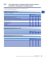
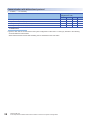
Correspondence between Data Communication Functions and System Configurations . . . . . . . . . . . . . 37
CHAPTER 4
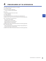
PROCEDURES UP TO OPERATION
39
CHAPTER 5
SYSTEM CONFIGURATION
41
5.1
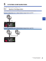
System Configuration . . . . . . . . . . . . . . . . . . . . . . . . . . . . . . . . . . . . . . . . . . . . . . . . . . . . . . . . . . . . . . . . . . . . 41
5.2
System Example that can be Constructed . . . . . . . . . . . . . . . . . . . . . . . . . . . . . . . . . . . . . . . . . . . . . . . . . . . 43
CHAPTER 6
6.1
WIRING
44
RS-232 Interface Connection Method (For Full-Duplex Communications) . . . . . . . . . . . . . . . . . . . . . . . . . 44
Considerations for connection . . . . . . . . . . . . . . . . . . . . . . . . . . . . . . . . . . . . . . . . . . . . . . . . . . . . . . . . . . . . . . . 44
Connection examples . . . . . . . . . . . . . . . . . . . . . . . . . . . . . . . . . . . . . . . . . . . . . . . . . . . . . . . . . . . . . . . . . . . . . 45
6.2
RS-422/485 Interface Connection Method. . . . . . . . . . . . . . . . . . . . . . . . . . . . . . . . . . . . . . . . . . . . . . . . . . . . 46
Considerations for connection . . . . . . . . . . . . . . . . . . . . . . . . . . . . . . . . . . . . . . . . . . . . . . . . . . . . . . . . . . . . . . . 46
Connection examples . . . . . . . . . . . . . . . . . . . . . . . . . . . . . . . . . . . . . . . . . . . . . . . . . . . . . . . . . . . . . . . . . . . . . 48
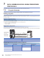
CHAPTER 7
7.1
DATA COMMUNICATION USING PREDEFINED PROTOCOLS
50
Program Example . . . . . . . . . . . . . . . . . . . . . . . . . . . . . . . . . . . . . . . . . . . . . . . . . . . . . . . . . . . . . . . . . . . . . . . 50
Setting programs . . . . . . . . . . . . . . . . . . . . . . . . . . . . . . . . . . . . . . . . . . . . . . . . . . . . . . . . . . . . . . . . . . . . . . . . . 50
14
APPENDIX
58
Appendix 1 External Dimensions . . . . . . . . . . . . . . . . . . . . . . . . . . . . . . . . . . . . . . . . . . . . . . . . . . . . . . . . . . . . . . . . 58
INDEX
60
REVISIONS. . . . . . . . . . . . . . . . . . . . . . . . . . . . . . . . . . . . . . . . . . . . . . . . . . . . . . . . . . . . . . . . . . . . . . . . . . . . . .62
WARRANTY . . . . . . . . . . . . . . . . . . . . . . . . . . . . . . . . . . . . . . . . . . . . . . . . . . . . . . . . . . . . . . . . . . . . . . . . . . . . .63
CONTENTS
TRADEMARKS . . . . . . . . . . . . . . . . . . . . . . . . . . . . . . . . . . . . . . . . . . . . . . . . . . . . . . . . . . . . . . . . . . . . . . . . . . .64
15
RELATED MANUALS
User's manuals for the module
Manual name [manual number]
Description
Available form
MELSEC iQ-R Serial Communication Module User's Manual
(Startup)
[SH-081250ENG] (this manual)
Specifications, list of functions, procedures prior to operation,
system configurations, wring, and data communication examples
of Serial communication module
Print book
e-Manual
EPUB
PDF
MELSEC iQ-R Serial Communication Module User's Manual
(Application)
[SH-081251ENG]
Functions, input/output signals, buffer memory, parameter setting,
and trouble shooting of Serial communication module
Print book
e-Manual
EPUB
PDF
MELSEC Communication Protocol Reference Manual
[SH-080008]
Specifications, accessible range, message protocols, and
functions of MELSEC Communication Protocol
Print book
e-Manual
EPUB
PDF
The following detailed information is not included in this manual.
• General specification
• Usable CPU module and the number of modules can be connected
• Installation
For more detail information, refer to the following manual.
MELSEC iQ-R Module Configuration Manual
e-Manual refers to the Mitsubishi FA electronic book manuals that can be browsed using a dedicated tool.
e-Manual has the following features:
• Required information can be cross-searched in multiple manuals.
• Other manuals can be accessed from the links in the manual.
• The hardware specifications of each part can be found from the product figures.
• Pages that users often browse can be bookmarked.
16
TERMS
Unless otherwise specified, this manual uses the following terms.
Term
Description
CPU module
A generic term for MELSEC iQ-R series CPU module
C24
Another term for MELSEC iQ-R series Serial Communication Module
Intelligent function module
A generic term for modules which has functions other than input and output, such as A/D converter module and D/A
converter module
Engineering tool
Another term for MELSEC programmable controller software packages
MC protocol
An abbreviation for MELSEC communication protocol, which is a name of communication method to access a CPU module
form a target device using the communication procedure for Serial communication modules or Ethernet communication
modules
3C frame
(Format 1 to Format 4)
4C frame
(Format 1 to Format 4)
A message format for C24 for data communications with ASCII code data using the MC protocol
This is the same message format as the communication frame using the dedicated protocol for the QnA series Serial
Communication Module.
• QnA compatible 3C frame (Format 1 to 4): QnA frame (Format 1 to 4)
• QnA compatible 4C frame (Format 1 to 4): QnA extension frame (Format 1 to 4)
4C frame
(Format 5)
A message format for C24 for data communication with binary code data using the MC protocol
This is the same message format as the communication frame using the dedicated protocol for the QnA series Serial
Communication Module.
• QnA compatible 4C frame (Format 5): QnA extension frame (Format 5)
Predefined protocol
A data communication function to send/receive data using a protocol of the target device for data communication between
C24 and the target device
This setting is configured with GX Works3 (the predefined protocol support function).
Predefined protocol support
function
A function available using GX Works3 (the predefined protocol support function)
The function includes the following:
• Setting the protocol appropriate to respective target devices
• Writing or reading the protocol setting data to/from CPU module or C24
• Debug support function
Nonprocedural protocol
A data communication function to communicate any data between a CPU module and the target device using user's
communication procedure
Bidirectional protocol
A data communication function to communicate any data between a CPU module and the target device using the
communication procedure for C24
Data communication function
A generic term for MC protocol, predefined protocol, nonprocedural protocol, and bidirectional protocol
Buffer memory
A memory of an Intelligent function module to store data (including setting value and monitored value) sent to/receive from
CPU module
Packet
A data string used for communication with a target device by predefined protocol
Multidrop connection
A name of connection when more than one target devices or other C24s are connected on a 1:n basis or an m:n basis using
the RS-422/485 interface of C24
User frame
A data name used to send/receive data by registering the fixed format part of messages to be sent/received between C24
and the target device to the module (The contents of a user frame data should conform to the specifications of the target
device.)
The data array of the head and tail sections in messages to be sent/received (transmission control code, C24 station
number, sum check, fixed data, etc.) are registered to C24 respectively before use.
This is used for the on-demand function of MC protocol and the data transmit/receive function by nonprocedural protocol.
Target device
A generic term for GOT, measuring instruments, ID modules, barcode readers, regulators, and other C24s connected to this
C24 for data communication
Independent operation
A mode of interface operation to communicate data with the target device with a function specified in each communication
protocol setting without interaction between two interfaces of C24
Interlink operation
A mode of interface operation to communicate data with the target device with the two interfaces linked one another when
two interfaces of C24 are connected to target devices respectively
The two interfaces communicate data with the same data communication function (MC protocol (identical format) or
nonprocedural protocol) and the same transmission specifications. (Linked operation of the predefined protocol and the
bidirectional protocol is not allowed.)
17
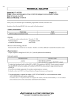
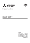
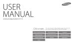
1
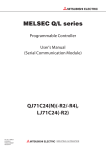
PART NAMES
This chapter explains the part names of C24.
RJ71C24
(1)
(1)
(1)
(2)
(2)
(4)
(3)
(2)
(4)
(5)
(5)
(5)
No.
Name
Description
1)
RUN LED
Displays the operation status.
ON: Normal
OFF: Critical error occurred
ERR LED*1
Displays the module error status.
ON: Error has occurred*2, *3
Flashing: Parameter error occurred
OFF: Normal
SD LED
Displays the data transmission status.
ON/Flashing: Data being transmitted
OFF: Data not transmitted
RD LED
Displays the data reception status.
ON/Flashing: Data being received
OFF: Data not received
C ERR LED
Displays the communication error status.
ON: Communication error has occurred
OFF: Normal
2)
RS-232 interface
RS232 interface for serial communication with target devices (D-Sub 9 pin female (mating screw M2.6))
3)
RS-422/485 interface
RS422/485 interface for serial communication with target devices (2-piece terminal block)
4)
RS-422/485 interface
RS422/485 interface for serial communication with target devices (2-piece plug-in socket block)
Production information display
Displays the production information (16 digits) of the module.
5)
*1
*2
*3
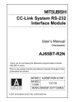
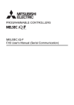
18
RJ71C24-R4
RJ71C24-R2
For the LED display during hardware test or self-loopback test, refer to the following sections.
MELSEC iQ-R Serial Communication Module User's Manual (Application)
This turns ON when an error occurs at C24 hardware or during data communication.
MELSEC iQ-R Serial Communication Module User's Manual (Application)
Turning 'Error initialization request' (YE) ON turns the LED OFF.
However, the LED turns ON again if the error state is not cleared when 'Error initialization request' (YE) is turned OFF.
1 PART NAMES
MEMO
1
1 PART NAMES
19
2
SPECIFICATIONS
This chapter explains performance specifications, RS-232 interface specifications, RS-422/485 interface specifications, and
modem specifications.
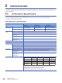
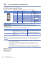
2.1
Performance Specifications
The following shows the C24 performance specifications.
For the transmission specifications when communicating via the modem function, refer to the following section.
Page 30 Transmission specifications
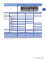
Transmission specification
Item
Interface
Communication
method
Specifications
RJ71C24
RJ71C24-R2
RJ71C24-R4
CH1
RS-232-compliance
(D-sub 9 pin female)
RS-232-compliance
(D-sub 9 pin female)
RS-422/485-compliance
(2-piece plug-in terminal block)
CH2
RS-422/485-compliance
(2-piece terminal block)
RS-232-compliance
(D-sub 9 pin female)
RS-422/485-compliance
(2-piece plug-in terminal block)
Line
Full-duplex/half-duplex communications
MC protocol communication
Half-duplex communications
Predefined protocol
communication
Full-duplex/half-duplex communications
Nonprocedural protocol
communication
Full-duplex/half-duplex communications
Bidirectional protocol
communication
Full-duplex/half-duplex communications
Synchronization method
Start-stop synchronization method
Transmission speed
1200/2400/4800/9600/14400/19200/28800/38400/57600/115200/230400(bps)
Data format
Access cycle
Start bits
1
Data bits
7/8
Parity bits
1 (vertical parity) or none
Stop bits
1/2
MC protocol communication
Processes one request during the END processing of the CPU module of the station with the C24.
Predefined protocol
communication
Sends or receives data when requested with the dedicated instruction (CPRTCL).
Nonprocedural protocol
communication
Bidirectional protocol
communication
Sends each time a send request is issued. Can receive at any time.
Error detection
MC protocol
communication
•
•
•
•
•
20
2 SPECIFICATIONS
2.1 Performance Specifications
Predefined protocol Nonprocedural protocol Bidirectional protocol
communication
communication
communication
Parity check
Enabled
Enabled
Enabled
Enabled
Sum check
Horizontal parity
16-bit CRC
(for MODBUS)
Enabled
Disabled
Enabled
Enabled
Enabled
Enabled
Enabled
Disabled
Disabled
Enabled
Disabled
Disabled
MC protocol communication: Select with parameters.
Predefined protocol communication: Select with the Predefined protocol support function.
Nonprocedural protocol communication: Set with user frames.
Bidirectional protocol communication: Select with parameters.
Parity check: Select odd/even of parity bit (vertical bit) with parameters.
Item
Specifications
RJ71C24
RJ71C24-R2
Transmission control
RJ71C24-R4
RS/CS control
RS-232
Enabled
Enabled
RS-422/485
Disabled
Disabled
CD(DCD) signal control
Enabled
Disabled
DC1/DC3 (Xon/Xoff) control
DC2/DC4 control
Enabled
Enabled
DTR/DSR control
2
• DTR/DSR signal control and DC code control are selected by the user.
Line configuration
for connection
(Target device
side: CPU module
side)*1
RS-232
1:1
1:1
RS-422/485
1:1, 1:n, n:1, m:n
1:1, 1:n, n:1, m:n
Line configuration
for data
communication
(Target device
side: CPU module
side)*1
RS
232
MC protocol
communication
1:1
1:1
Predefined protocol
communication
1:1
1:1
Nonprocedural protocol
communication
1:1
1:1
Bidirectional protocol
communication
1:1
1:1
MC protocol
communication
1:1, 1:n, m:n
Predefined protocol
communication
1:1, n:1
1:1, n:1
Nonprocedural protocol
communication
1:1, 1:n, n:1
1:1, 1:n, n:1
Bidirectional protocol
communication
1:1
1:1
RS
422
/
485
Transmission
distance
(Overall distance)
RS-232
Maximum 15 m
Maximum 15 m
RS-422/485
Maximum 1200 m (overall
distance)
Maximum 1200 m (overall
distance)
Number of occupied I/O points
32 points (I/O assignment: Intelli: 32 points)
Applicable connector for external wiring
D-sub 9 pin (male) screw type*2
5V DC internal current consumption
0.31 A
External dimensions
106(H) 27.8(W) 110(D)[mm]
Weight
0.16 kg
*1
*2
1:1, 1:n, m:n
0.20 A
0.42 A
0.14 kg
0.13 kg
The total number of 'n' or 'm+n' is up to 32.
For more information on recommended connectors, refer to the following section.
Page 23 Interface connector
2 SPECIFICATIONS
2.1 Performance Specifications
21
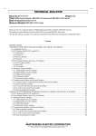
2.2
RS-232 Interface Specification
The following shows the RS-232 interface specifications.
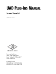
RS-232 connector specifications
The following table shows the specifications of the RS-232 connector that connects C24 to a target device.
Connector
1
2
3
4
5
6
7
8
9
Pin number
Signal number
Signal name
1
CD(DCD)
Data carrier detect
2
RD(RXD)
Receive data
3
SD(TXD)
Send data
4
ER(DTR)
Data terminal ready
5
SG
Signal ground
6
DR(DSR)
Data set ready
7
RS(RTS)
Request to send
8
CS(CTS)
Clear to send
9
CI(RI)
Ring indicator
Direction
C24 target device
Control signals
The following explains the control signals. (The pin numbers of the connector are enclosed in parentheses.)
■CD(DCD) signal (1)
• C24 operates according to the setting with the CD terminal check designation of C24.
CD terminal check is enabled
Full-duplex communication
• C24 performs the send and receive processing when
the CD(DCD) signal is ON.
• When the CD(DCD) signal is turned OFF during data
communication, C24 initializes the transmission
sequence.
Half-duplex communication
MELSEC iQ-R Serial Communication Module User's
Manual (Application)
CD terminal check is disabled
• C24 performs the send and receive processing
regardless of the ON/OFF status of the CD(DCD)
signal.
• Data communications is possible with a target device
that cannot turn the CD(DCD) signal ON/OFF.
Not applicable
Configure the setting of CD terminal check with the following setting items of Engineering tool.
Navigation window [Parameter] [Module Information] Module Name [Module Parameter] "Basic Settings"
"Various control specification" "Communication control specification" "CD terminal check designation"
When the CD terminal check is set to be enabled for full-duplex communications, set the CD signal of C24 in
the ON state during data transmission.
• When the CD signal is turned OFF while data is being transmitted to the target device using the
nonprocedural protocol, C24 stops the transmission, and turns ON the 'CH Transmission normal
completion' (X0/X7).
• If the CD signal is OFF when starting data transmission to the target device using the nonprocedural
protocol, C24 does not transmit data, and turns ON the 'CH Transmission normal completion' (X0/X7).
■RD(RXD) signal (2)
A signal to receive data
■SD(TXD) signal (3)
A signal to send data
22
2 SPECIFICATIONS
2.2 RS-232 Interface Specification
■ER(DTR) signal (4)
• When communicating data using the nonprocedural protocol, C24 turns ON or OFF (ON when data is receivable)
depending on the unused memory size in the OS area allocated for receive data storage, if DTR/DSR control is performed.
Read the receive data from the program, as the receive data is stored in the OS area when the ER(DTR) signal is OFF.
If DTR/DSR control is not performed, the ER(DTR) signal is always ON.
2
• When communicating data using the MC protocol or bidirectional protocol, C24 turns ON when communications is enabled.
■DR(DSR) signal (6)
• During DTR/DSR control, C24 does not send data to the target device when this signal is OFF.
Be sure that this signal is always turned ON when the target device is ready to receive.
• If DTR/DSR control is not performed, the DR(DSR) signal status is ignored.
■RS(RTS) signal (7)
C24 turns ON/OFF the RS(RTS) signal as shown below depending on the communication method.
• When the communication method is full-duplex communications, if the 'C24 READY' (X1E) is ON, C24 turns ON the
RS(RTS) signal.
• When the communication method is half-duplex communications, it turns ON the RS(RTS) signal when C24 sends data to
a target device.
• The RS(RTS) signal is not turned OFF even when the receive data cannot be stored in C24.
■CS(CTS) signal (8)
• C24 does not send data to a target device when this signal is OFF.
• Be sure that this signal is always turned ON when the target device is ready to receive.
■CI(RI) signal (9)
• The CI(RI) signal is used when the modem status is monitored on C24 side.
It should be connected as needed.
The CI(RI) signal is not needed to be connected when the modem is not connected.
ON and OFF states of signal
The ON and OFF states of each signal indicate the following conditions:
Output side
Input side
ON
5 VDC to 15 VCD
3 VDC to 15 VDC
OFF
-15 VDC to -5 VDC
-15 VDC to -3 VDC
Interface connector
The following connector model is used as RS-232 interface connector for C24.
• 9-pin D-sub (female) screw type (mating screw M2.6)
17L-10090-27 (D9AC) (-FA)
Manufactured by DDK Ltd.
The suitable connector shell for the RS-232 connector is as shown below.
Type
Model
Connector shell
17JE-23090-02(D8A)(-CG)*1
*1
Manufactured by DDK Ltd.
Tightening torque
For details on the tightening torque for the RS-232 interface connector, refer to the following section.
Page 44 Considerations for connection
2 SPECIFICATIONS
2.2 RS-232 Interface Specification
23
Remarks
■Confirmation of RS-232 control signal status
During data communication, the status of each control signal of ER(DTR), DR(DSR), RS(RTS), and CD(DCD) can be
confirmed with 'RS-232 control signal status' (Un\G596/612).
Bit position
Buffer memory address
CH1 side
CH2 side
Un\G596
Un\G612
b0
RS(RTS)
b1
DR(DSR)
b2
ER(DTR)
b3
CD(DCD)
b4
CS(CTS)*1
b5
CI(RI)
b6 to b15
*1
System area for RJ71C24 (-R2)
■RS and DTR signal status designation
Normally, C24 turns ON/OFF the RS(RTS) signal or ER(DTR) signal.
The ON/OFF status of the RS(RTS) or ER(DTR) signal can be specified by turning ON/OFF the corresponding bit in the 'RS
and DTR signal status designation' (Un\G146/306). *1,*2,*3,*4
b15
b3 b2 b1 b0
Buffer memory address Un\G146/306
1/0
1/0
For system
*1
*2
*3
*4
(Default 0005H)
RS(RTS)
ER(DTR)
1: ON
0: OFF
The RS(RTS) signal is controlled by C24 in the following cases. (The setting contents are ignored.)
When data is communicated with half-duplex communication
When RS/CS control is performed during communication with the modem function
The ER(DTR) signal is controlled by C24 in the following cases. (The setting contents are ignored.)
When the DTR/DSR signals are controlled
When data is communicated with the modem function
After writing in the buffer memory, a lag of 0 to 20 ms occurs until it is reflected in the signal.
When RS and DTR signal status designation (protocol No.: 204 to 207) for a functional protocol is performed with the CPRTCL
instruction, the corresponding bit in the 'RS and DTR signal status designation' (Un\G146/306) turns ON or OFF.
For details on functional protocol, refer to the following manual.
MELSEC iQ-R Programming Manual (Instructions, Standard Functions/Function Blocks)
Be sure to control the RS(RTS) and ER(DTR) signals with the C24 system.
Control of the RS(RTS) and ER(DTR) signals by a user may cause data communication errors.
RS-232 cable specification
Use a cable of 15 m (49.21ft) or shorter, which conforms to the RS-232 standard as the RS-232 cable.
Diameter
Type
Material
Temperature rating
AWG28 to 24
Stranded
Copper
60 or more
• Reference
Oki Electric Cable Co., Ltd.
7/0.127 P HRV-SV
: Specify the number of pairs. (For 13 pairs 7/0.127 13P HRV-SV)
24
2 SPECIFICATIONS
2.2 RS-232 Interface Specification
2.3
RS-422/485 Interface Specifications
The following explains the RS-422/485 interface specifications.
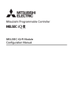
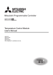
RS-422/485 terminal block specifications
2
The following table shows the specifications of the RS-422/485 terminal block that connects to a target device.
Terminal block
Terminal block
(RJ71C24)
SG
SLD
(FG)
SDA
SDB
RDA
RDB
Plug-in terminal block
(RJ71C24-R4)
SDA
SDB
RDA
RDB
SG
SLD
(FG)
Abbreviation
Signal name
SDA
Transmitted data (+)
SDB
Transmitted data (-)
RDA
Received data (+)
RDB
Received data (-)
SG
Signal ground
SLD
*1
FG*1
*1
Direction
C24 Target device
Shield wire of cable
Frame ground
The SLD and FG are connected inside the module.
Control signals
The following explains the control signals.
■SDA, SDB signals
Signals to send data from C24 to the target device.
■RDA, RDB signals
Signals for C24 to receive data from the target device.
Terminating resistor
For more information of terminating resistor connection, refer to the following section.
Page 46 Considerations for connection
Terminal
■Terminal block (RJ71C24)
Use 1.25-3 for the solderless terminal to be attached on the terminal block.
Use the UL certified solderless terminal. For crimping the terminal, use the tools recommended by solderless terminal
manufacturers. Solderless terminals with insulation sleeves cannot be used.
■Plug-in terminal block (RJ71C24-R4)
Remove the shielded part of the cable and directly connect the cable to the plug-in socket block.
Use the plate terminal (supplied with the product) to connect the braided shield wire to the FG terminal on the plug-in terminal
block.
Tightening torque
For details on the tightening torque for the RS-422/485 terminal block, refer to the following section.
Page 46 Considerations for connection
2 SPECIFICATIONS
2.3 RS-422/485 Interface Specifications
25
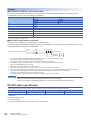
RS-422/485 cable specifications
The following table shows the RS-422/485 cable specifications.
• Use a cable of 1200 m (3937 ft.) or shorter, which satisfies the following specifications for the RS-422/485 cable (cable
connected to the terminal block on C24).
Item
Description
Cable type
Shielded cable
Number of pairs
3P
Conductor resistance (20)
88.0/km or less
Insulation resistance
10000M-km or more
Dielectric strength
500 VDC, 1 minute
Electrostatic capacitance (1 kHz)
60nF/km or less on average
Characteristic impedance (100 kHz)
11010
Recommended conductor size
0.2 to 0.75
Diameter
AWG22 to AWG16
Type
Stranded
Material
Copper
Temperature rating
60 or more
• Recommended cable
Cable model
Manufacturer
HRZEV-ME(20276)AWG223P
DYDEN CORPORATION
SPEV(SB)-MPC-0.23P
MITSUBISHI CABLE INDUSTRIES, Ltd.
SPEV(SB)-0.23P
MITSUBISHI CABLE INDUSTRIES, Ltd.
SPEV(SB)-0.33P
MITSUBISHI CABLE INDUSTRIES, Ltd.
The recommended cables shown above have the same electrical characteristics, but external diameter and internal wire
colors are slightly different.
• Make the total distance within 1200 m (3937 ft.) when more than one device is connected on a 1:n, n:1, or m:n basis.
26
2 SPECIFICATIONS
2.3 RS-422/485 Interface Specifications
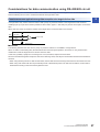
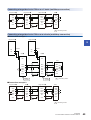
Considerations for data communication using RS-422/485 circuit
Take the following into consideration for data communication with a target device through the C24 RS-422/485 interface.
Take the following into account to send/receive data at the target device side.
2
Countermeasures against wrong data reception at a target device side
If a target device may receive erroneous data, install a pull-up or pull-down resistor to the target device side as follows.
Installing a pull-up or pull-down resistor (resistance value criteria: approx. 4.7k1/4W) can prevent the reception of erroneous
data.
When there is a pull-up or pull-down resistor on the target device, erroneous data is not received.
RDA
4.7kΩ 1/4W
RDB
Terminating
resistor
4.7k 1/4W
+
-
Received data
Target device
■Remarks
The following describes the case when a pull-up or pull-down resistor is not installed to a target device.
When no station is transmitting data, the transmission line becomes high impedance, and noise, etc. may make the line
unstable and cause the target device to receive erroneous data.
In this case, probably a parity error or framing error occurs, therefore, skip the erroneous data.
Since the first data during data reception is fixed in the following cases, also skip the receive data until the fixed head data is
received.
• When using the MC protocol for data communication, the first data is fixed according to the frame and format the user uses.
• When using user frames with the nonprocedural protocol or bidirectional protocol for data communication, the first data is
determined according to the user frame registered to C24.
2 SPECIFICATIONS
2.3 RS-422/485 Interface Specifications
27
RS-422/485 interface operation
■RS-422-485 interface structure
The following diagram shows the structure of the C24 RS-422/485 interface driver (send)/receiver (receive).
SDA
Driver
Sent data
SDB
RDA
Output control input (*1)
Receiver
Received data
RDB
*1
'Output control input' (also called send gate) of the driver (send) section of the illustration above determines whether or not data from
SDA/SDB is output to the outside.
■RS-422/485 interface operation
When the 'Output control input' in the illustration above is ON, the interface enters the low impedance state (state in which
data can be sent).
To the contrary, when the 'Output control input' is OFF, the interface enters the high impedance state (state in which data is not
sent).
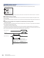
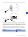
■Timing to start sending and to complete the transmission processing of C24
• Timing to start sending
During data transmission, C24 outputs the actual data after sending a mark of 2 characters or longer after the high impedance
by the operations described above is reset.
• Transmission processing completion timing
The following time is required as hardware gate OFF time from the completion of data transmission to the completion of
transmission processing (the state changes to the high impedance state). (This applies to the transmission speed set in C24.)
When the transmission speed is 1200 bps or higher: Data transfer time of less than 1 bit
(Output control input)
Data
Target device
Data
C24
(Output control input)
Outputs a mark of 2 characters or longer
Data send time range
H/W gate OFF time
(Refer to explanation above)
"Output control input" ON
time range
(Low impedance state)
C24 is in the datasendable/receivable state
28
2 SPECIFICATIONS
2.3 RS-422/485 Interface Specifications
"Output control input" OFF
time range
(High impedance state)
C24 is in the
data-receivable state
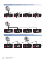
Precautions
• For multidrop connection
When the send signal of each device is connected as shown below, if the 'Output control input' is turned ON at two or more
devices, the relevant devices output (send) data at the same time.
2
The target device side must turn ON the 'Output control input' only when sending data or must turn OFF the 'Output control
input' when not sending data for the normal data communication.
The C24 side automatically controls the output control input.
Target device or converter
Sent data
SDA
SDB
Output control input
Received
data
RDA
RDB
SDA
Sent data
SDB
Output control input
RDA
RDB
C24
Received
data
SDA
Sent data
SDB
Output control input
RDA
RDB
C24
Received
data
• When two interfaces are in the interlink operation in C24, the transmission time for one character becomes equal to the
hardware gate OFF time of C24. (C24 turns OFF the gate after the transmission time for one character following the data
transmission.)
2 SPECIFICATIONS
2.3 RS-422/485 Interface Specifications
29
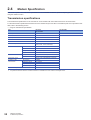
2.4
Modem Specification
This section explains the transmission specifications and connectable modem/TA (terminal adapter) specifications when
using the modem function.
Transmission specifications
The transmission specifications on the C24 side for communication with the modem function are as shown below.
For the transmission specifications between C24 and a modem/TA (the C24 side on host station) that are not provided in this
table, refer to the following section.
Page 20 Transmission specification
Item
RJ71C24
RJ71C24-R2
RJ71C24-R4
Availability of modem function
Available
Not available
Interface that can use the modem function
RS-232
Interlink operation between CH1 and CH2 of C24
Not available
Communication method
Full duplex communication
Synchronization method
Asynchronous method
Transmission speed
1200, 2400, 4800, 9600, 14400, 19200, 28800,
38400, 57600, 115200, 230400(bps)
Data format
Error detection
Start bit
1
Data bit
7/8
Parity bit
1 (Exist)/0 (None)
Stop bit
1/2
Parity check
Yes (odd/even selectable)/None
Sum check code
Transmission control
Availability of data
communication
MC protocol*1
Available
Predefined protocol
Not available
Nonprocedural protocol
Available
Bidirectional protocol
Available
Line connection (C24: modem)
*1
30
Yes/None
RS/CS control enabled/disabled (selectable)
1:1
Only data transmission with the on-demand function is available from CPU module to the target device.
2 SPECIFICATIONS
2.4 Modem Specification
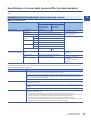
Specification of connectable modems/TAs (terminal adapters)
The table below shows the specifications of modems/TAs that can be connected to the C24 side when the modem function is
used.
2
Specifications of and considerations for the connectable modems
■Modem specification
Item
Specification
When using the
public line/office
telephone system
Modem-to-modem
communication specifications
*1
When using a
manual line
connection
Connection line
Analog 2-line
Initialization
Hayes AT command compatible
Telephone line
A line equivalent to NTT communication protocol
MELSEC iQ-R Serial
Communication Module User's
Manual (Application)
Communication
standard
C24-to-modem
communication specifications
Remarks
ITU-T
V.34/V.32bis/V.32/V.22bis/V.22/V.21/V.fc
Bell
212A/103
Error correction
MNP
Class 4 and 10 compliant
ITU-T
V.42 compliant
Data compression
MNP
Class 5 compliant
ITU-T
V.42bis compliant
ANS-ORG mode switch
C24 side connector (RS232)
D-sub 9 pin (female)
Page 20 Transmission
specification
DR signal control*1
Capable of turning ON the DR(DSR) signal only
Other
Compatible with C24 specification
Page 20 Transmission
specification
Page 30 Transmission
specifications
Capable of switching
mode
Modems which turn ON the CD(DCD) signal simultaneously cannot be used.
The following are the functions of the modem itself that become available by issuing the AT commands to the modem. For
details, refer to the modem's instruction.
Item
Description
Error correction
When a noise occurs on the line, data corruption may occur due to interrupted communication data.
The error correction function is intended to suppress effects from such noises.
If an error such as data corruption is detected by the error correction function, the modem retries the transmission.
When the number of retries has exceeded the modem's limit, the modem determines that it's under the environment
where communication cannot be established.
Both modems must support the MNP4 or V.42 protocol.
Data compression
This function compresses data to be sent prior to transmission, and decompress the compressed data upon reception,
then forwards to the terminal.
The data compression is effective for the execution speed at a maximum of 200 % for the MNP5 and 300 % for the
V.42bis.
Both modems must support the MNP5 or V.42bis protocol.
Flow control (RS/CS control)
When communication between a modem and terminal is faster than between two modems, the flow control is
performed in the following order:
• The modem transmits data to the target by storing the data from the terminal in the modem buffer.
• When the buffer in the modem becomes almost full, the modem outputs a data transmission temporary stop request
(CS(CTS) signal = OFF) to the terminal. The terminal pauses data transmission by the request.
Even while the terminal pauses data transmission, the modem continues to send data to the partner.
• When the buffer has free space, the modem outputs a data transmission resuming request (CS(CTS) signal = ON)
to the terminal. The terminal resumes data transmission to the modem by the request.
2 SPECIFICATIONS
2.4 Modem Specification
31
■Considerations for selecting a modem
• Modem setting
Configure the setting as shown below for a modem to be connected to the C24 side
Setting item
Setting range
Communication rate
Depends on the modem in use*1
Modem command
Hayes AT command
SI/SO control
None
Communication method
Nonprocedural
Data format
Match with C24*2, *3
Data bit
Stop bit
Parity bit
*1
*2
*3
When using different modems, the slower communication rate will be in effect.
Some modems may transmit one character as 10 bits.
Check the modem specifications when setting C24 transmission specifications.
Some modems may switch the communication rate following the start of data communication.
Since C24 cannot switch the communication rate, set the modem side so that its communication rate does not switch.
When using a modem whose DR terminal (signal) is set by a switch, set the DR terminal (modem output) switch level to High.
When using a modem requiring DR terminal setting with software, write the command that turns ON the DR (DSR) signal into
the data for initialization. Set the "DR signal valid/invalid designation for modem initialization" to "Invalid" in "modem function
setting" with Engineering tool.
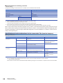
Specifications of and considerations for the connectable TAs (terminal adapters)
■TA specification
Item
TA-to-TA communication
specifications
C24-to-TA communication
specifications
*1
32
Specification
Remarks
Connection line
ISDN (INS net 64) equivalent, High-speed digital
dedicated line
DSU and TA are required
Initialization
Hayes AT command compatible
MELSEC iQ-R Serial
Communication Module User's
Manual (Application)
Communication standard
B-channel line exchange (V.110)
D-channel packet exchange
Electrical condition
V.28 compliant
Circuit definition
V.24 compliant
C24-side connector (RS-232)
D-sub 9 pin (female)
Page 20 Transmission
specification
DR signal control*1
Capable of turning ON the DR(DSR) signal only
Other
Compatible with C24 specification
Page 20 Transmission
specification
Page 30 Transmission
specifications
TAs that turn ON the CD (DCD) signal simultaneously cannot be used.
Use a TA capable of flow control as described below also for the communication between the TA and terminal.
Page 31 Modem specification
Flow control is a function of the TA itself that becomes available by issuing the AT commands to TA. Refer to the TA manual for details.
2 SPECIFICATIONS
2.4 Modem Specification
■Considerations for selecting a TA
• Configure the setting as shown below for a TA to be connected to the C24 side.
Setting item
Setting range
Communication rate
Depends on the TA in use
Modem command
Hayes AT command
SI/SO control
None
Communication method
Nonprocedural
Data format
Data bit
2
Match with C24*1, *2
Stop bit
Parity bit
*1
*2
Some TAs may transmit one character as 10 bits.
Check the TA specifications when setting C24 transmission specifications.
Some TAs may switch the communication rate following the start of data communication.
Since C24 cannot switch the communication rate, set the TA side so that its communication rate does not switch.
• When using a TA whose DR terminal (signal) is set by a switch, set the DR terminal (TA output) switch level to High.
When using a TA requiring DR terminal setting with software, write the command that turns ON the DR (DSR) signal into
the data for initialization. Set the "Modem initialization DR (DSR) signal enable/disable designation" to "DR signal enabled"
in the modem function setting with Engineering tool.
2 SPECIFICATIONS
2.4 Modem Specification
33
3
3.1
FUNCTION LIST
Function List
This section lists the functions of C24. For more details on the functions, refer to the following manual.
MELSEC iQ-R Serial Communication Module User's Manual (Application)
Basic functions
The following shows the basic functions of C24.
Function
Communication with MC protocol
Description
Reading/writing from/to device memory of
CPU module
Performs batch read/write in bit/word units.
Performs monitoring of device memory.
Performs batch read/write of multiple blocks.
Performs read/write by extension designation.
Accesses other stations via network system.
34
Reading/writing from/to the buffer memory
of C24
Performs reading/writing from/to the buffer memory of C24.
Reading/writing from/to the buffer memory
of Intelligent function modules
Performs reading from/writing to the buffer memory of intelligent
function modules.
Reading/writing from/to program files and
parameter files
Performs reading/writing from/to program files and parameter files
stored in the CPU module.
Controlling the status of the CPU module
(such as remote RUN/STOP)
Performs status control of the CPU module.
Performs remote RUN/STOP/PAUSE/latch clear/reset operations
from target devices.
Communication with predefined protocol
Transmitting/receiving data
Performs data transmission/reception with the appropriate protocol
for each target device.
The protocol of the target device can be easily selected, or
created/edited using the predefined protocol library of Engineering
tool.
Communication with nonprocedural
protocol
Transmitting/receiving data in any format
Data communication can be performed in any message format
according to specifications of target devices (measuring devices,
personal computers etc.).
Communication with bidirectional protocol
Transmitting/receiving data in any format
Any data transmission/reception can be performed with the
message format and transmission control procedures for the
bidirectional protocol.
Debug support function
Circuit trace
Traces transmitted/received data and communication control
signal between C24 and target devices.
Protocol execution log storage function
Checks the detailed execution status and results of the predefined
protocol for each channel.
3 FUNCTION LIST
3.1 Function List
Additional functions
The following shows the additional functions of C24.
The abbreviations used in the following list are as follows:
MC: MC protocol
Non: Nonprocedural protocol
Bi: Bidirectional protocol
Pd: Predefined protocol
Function
Description
3
Protocol
MC
Non
Bi
Pd
Performs data communications with 2C/3C/4C frame.
Performs data communications with 1C frame.
Communication with binary code
Performs data communication with 4C frame.
Monitoring CPU modules
(Programmable controller CPU monitoring
function)
Monitors the operating status of CPU modules and the data in the
device memory.
The CPU module status and the device memory data can be
transmitted to a target device at the fixed intervals, when an error
occurs in the machine equipment, or when certain conditions are
satisfied.
Turning ON/OFF input signals for C24 from a
target device (global function)
Turns ON/OFF input signals for C24 from a target device.
Transmitting data from a CPU module to a target
device (on-demand function)
Transmits data from a CPU module to a target device in each frame
format of the MC protocol.
Transmitting/receiving data with a user frame
Registers the fixed format portion of messages to be transmitted and
received between C24 and a target device in the module, which can be
used for data transmission/reception.
Receiving data by interrupt programs
Reads the received data from a target device with interrupt programs
so that the CPU module can receive data faster.
Transmitting/receiving ASCII data with ASCIIbinary conversion
Performs data communication with a target device with ASCII code
data with ASCII-binary conversion by C24.
Transmitting/receiving data by specifying
transparent code
Transmits/receives one-byte data for transmission control of the target
device side as a user data in data communications with a target
device.
Communication via public network, etc.
(Modem function)
Performs data communication via public line with a remotely-located
target device.
Data communications using the MC protocol, nonprocedural protocol,
and bidirectional protocol are available.
Transmission
control
DC code control
(including Xon/Xoff control)
Notifies the availability of data reception on the host station and the
effective range of transmitted/received data to target devices, using
data for transmission control of C24.
DTR/DSR control
Notifies the availability of data reception on the host station to target
devices, using ER(DTR)/DR(DSR) signal of the RS-232 interface
Independent operation of each interface
Performs data communications with a target device without
interconnecting the two interfaces of C24.
Interlink operation of each interface
Transmits all data received from either one of the two interfaces to the
other interface.
Parameter registration to CPU module
Configures the settings on the parameter setting screen of Engineering
tool, writes the settings to the CPU module, and reflects the settings by
restarting the CPU module.
Remote password check function
Checks the password with C24 when a remote user accesses to a
CPU module using the modem function. This function prevents
unauthorized accesses to the CPU module.
Enabling or disabling echo back of the RS-422/
485 interface
When data is transmitted through RS-485 (2 wire type) from the RS422/485 interface, transmitted data is sent back to RDA or RDB on the
host station. Whether to receive the returned data or not (discard) can
be designated with this function.
Preventing erroneous noise signal reception
Prevents noise signal generated when turning ON the power of a
target device or connecting a cable from being received in error by
corresponding to the settings of data communication start/stop.
Automatically removing NULL characters in
transmitted data
By removing automatically the NULL characters included in the data to
be transmitted, man-hours for design can be reduced.
Communication with ASCII code
3 FUNCTION LIST
3.1 Function List
35
Function
Dedicated instructions
36
3 FUNCTION LIST
3.1 Function List
Description
A instruction to use the functions of the module.
Protocol
MC
Non
Bi
Pd
3.2
Correspondence between Data Communication
Functions and System Configurations
The following shows the system configurations that can use the data communication functions of C24.
For the system configuration that can be configured, refer to the following section.
Page 41 SYSTEM CONFIGURATION
3
Communication with MC protocol
(: Available, : Not available)
Function
System configuration
(Target device: C24)
1:1
n:1
1:n
m:n
Reading/writing from/to device memory of CPU module
Reading/writing from/to the buffer memory of C24
Reading/writing from/to the buffer memory of Intelligent function modules
Reading/writing programs and parameters
Controlling the status of the CPU module
(Remote RUN, STOP, etc.)
Communication with ASCII code
Communication with binary code
On-demand function
Global function
Programmable controller CPU monitoring function
Communication with predefined protocol
(: Available, : Not available)
Function
System configuration
(Target device: C24)
Transmitting/receiving data
1:1
n:1
1:n
m:n
Communication with nonprocedural protocol
(: Available, : Not available)
Function
System configuration
(Target device: C24)
1:1
n:1
1:n
m:n
Transmitting/receiving data in any format
Transmitting/receiving data with a user frame
Programmable controller CPU monitoring function
Reading received data by interrupt programs
Transmitting/receiving ASCII data with ASCII-binary conversion
Transmitting/receiving data by specifying transparent code
3 FUNCTION LIST
3.2 Correspondence between Data Communication Functions and System Configurations
37
Communication with bidirectional protocol
(: Available, : Not available)
Function
System configuration
(Target device: C24)
1:1
n:1
1:n
m:n
Transmitting/receiving data in any format
Reading received data by interrupt programs
Transmitting/receiving ASCII data with ASCII-binary conversion
Transmitting/receiving data by specifying transparent code
Precautions
In general, when data is communicated in the system configuration of other than 1:1 basis, pay attention to the following.
• Avoid simultaneous transmission.
• Read and discard the received data excluding the one addressed to the host station.
38
3 FUNCTION LIST
3.2 Correspondence between Data Communication Functions and System Configurations
4
PROCEDURES UP TO OPERATION
This chapter explains the procedures up to operation.
1.
Mounting a module.
Mount C24 with desired configuration.
Page 41 SYSTEM CONFIGURATION
2.
Wiring
Connect C24 and target devices with a cable.
Page 44 WIRING
3.
4
Setting parameters
Set the C24 parameter with the basic settings using Engineering tool.
MELSEC iQ-R Serial Communication Module User's Manual (Application)
4.
Communication using each protocol
• MC protocol communication
• Predefined protocol communication
• Nonprocedural protocol communication
• Bidirectional protocol communication
MELSEC iQ-R Serial Communication Module User's Manual (Application)
5.
Using special function
• Set the C24 parameter with the application settings using Engineering tool.
• Communicate using the special functions.
MELSEC iQ-R Serial Communication Module User's Manual (Application)
4 PROCEDURES UP TO OPERATION
39
MEMO
40
4 PROCEDURES UP TO OPERATION
5
SYSTEM CONFIGURATION
This chapter explains the system configuration of C24.
5.1
System Configuration
System configurations (combinations of C24 and target devices) for data communication are shown below.
System configuration on a 1:1 basis between target device and C24
5
RS-232/422
System configuration on a n:1 basis between target device and C24
RS-485
5 SYSTEM CONFIGURATION
5.1 System Configuration
41
System configuration on a 1:n basis between target device and C24
RS-485
RS-232
RS-485
System configuration on a m:n basis between target device and C24
RS-485
42
5 SYSTEM CONFIGURATION
5.1 System Configuration
RS-232
RS-485
5.2
System Example that can be Constructed
The following shows examples of system configuration for C24.
Connecting two target devices to C24
Connect target devices such as GOT and barcode reader to a single C24.
Data can be sent and received between GOT and barcode reader via C24.
GOT
Barcode reader
5
RS-485
RS-232
Connecting a target device and more than one C24
Connect more than one C24 to a personal computer as the multidrop connection.
Data can be read from/written to the CPU module from a personal computer via C24.
For the combination of target devices and C24, refer to the following section.
Page 41 System Configuration
RS-232
RS-485
RS-485
5 SYSTEM CONFIGURATION
5.2 System Example that can be Constructed
43
6
WIRING
This chapter explains the wiring methods in the system using C24.
6.1
RS-232 Interface Connection Method (For FullDuplex Communications)
This section shows considerations for connection and connection examples for full-duplex communications using C24 RS-232
interface.
Considerations for connection
• Do not bundle control line and communication cable with the main circuit and the power cables, and do not install them
close to each other.
Keep a distance of 100 mm (3.94 in.) or more between them. Failure to do so may result in malfunction due to noise.
• Prior to connection to the target device side, check the specifications of the target device.
• Be sure the shield is single-point grounded.
• For more information for the following, refer to the relevant sections. (MELSEC iQ-R Serial Communication Module
User's Manual (Application))
Controlling communication on the C24 side at the target device side by using the CD(DCD) signal on RS-232 interface.
Performing half-duplex communications with the specifications of the target device side.
Using the modem function.
• Connect the FG signal of the connection cable and the shield as follows:
Connection cable
Connection on the C24 side
Remarks
FG signal of connection cable
Connect to C24 connector housing
Shield of connection cable
Connect to the FG terminal of the target device or the C24
connector housing
Do not short-circuit the FG and SG signals of the
connection cable.
When the FG and SG signals are connected inside the
target device, do not connect the FG signal to the C24
side.
• When normal data communication is not obtained due to external noise, perform the wiring as follows:
Connect the FG terminal on the target device to the C24 side using the shield of the connection cable.
Connect the signals other than SG to the SG signal with twisted pair cables.
C24
(Target device side)
Shield
To
Connector
housing
FG
SD(TXD)
RD(RXD)
RD(RXD)
SD(TXD)
DR(DSR)
ER(DTR)
ER(DTR)
DR(DSR)
SG
SG
• Tighten the connector screws within the following torque ranges.
44
Location of screw
Tightening torque
range
Remarks
RS-232 cable connector screw (M2.6 screw)
0.20 to 0.39Nm
Depth of hole: L = 3.2 mm (0.13 in.) or less (Internal length
from the surface)
6 WIRING
6.1 RS-232 Interface Connection Method (For Full-Duplex Communications)
Connection examples
With target device capable of turning ON/OFF the CD(DCD) signal (Pin No.1)
Target device
C24
Signal name
Pin No.
Signal name
CD(DCD)
1
CD(DCD)
RD(RXD)
2
RD(RXD)
SD(TXD)
3
ER(DTR)
4
SD(TXD)
ER(DTR)
SG
DR(DSR)
5
RS(RTS)
7
RS(RTS)
CS(CTS)
CI(RI)
8
CS(CTS)
6
SG
DR(DSR)
9
• Configure the CD terminal check designation according to the specification of the target device.
DTR/DSR control or DC code control is available with the wiring shown above.
With target device not capable of turning ON/OFF the CD(DCD) signal (Pin No.1)
6
■Connection example 1
C24
Target device
Signal name
Pin No.
Signal name
CD(DCD)
1
CD(DCD)
RD(RXD)
2
RD(RXD)
SD(TXD)
3
SD(TXD)
ER(DTR)
SG
4
ER(DTR)
5
SG
DR(DSR)
6
DR(DSR)
RS(RTS)
7
RS(RTS)
CS(CTS)
CI(RI)
8
CS(CTS)
9
• With the wiring shown above, DTR/DSR control or DC code control is available.
■Connection example 2
Target device
C24
Signal name
Pin No.
Signal name
CD(DCD)
1
CD(DCD)
RD(RXD)
2
RD(RXD)
SD(TXD)
3
ER(DTR)
SG
4
SD(TXD)
ER(DTR)
DR(DSR)
6
RS(RTS)
7
RS(RTS)
CS(CTS)
CI(RI)
8
CS(CTS)
5
SG
DR(DSR)
9
• With the wiring shown above, DC code control is available.
If the CPU module and the target device cannot be communicated at all, try to perform data communication
with the wiring connection shown in the connection example 2 as a connection test.
When data can be communicated with the wiring connection shown in the connection example 2, rewire after
checking the interface specifications of the target device side.
6 WIRING
6.1 RS-232 Interface Connection Method (For Full-Duplex Communications)
45
6.2
RS-422/485 Interface Connection Method
This section shows considerations for connection and connection examples when using C24 RS-422/485 interface.
Considerations for connection
• Do not bundle control line and communication cable with the main circuit and the power cables, and do not install them
close to each other.
Keep a distance of 100 mm (3.94 in.) or more between them. Failure to do so may result in malfunction due to noise.
• M3 screws are used for the terminal screw on RS-422/485 terminal block. Use 1.25-3 as the applicable solderless terminal.
Solderless terminals with insulation sleeves cannot be used for the terminal block.
Covering the wire connection parts of the solderless terminals with mark tubes or insulation tubes is recommended.
• When connecting the C24 SG and FG signals to the target device, connect them according to the specifications of the
target device.
• Be sure the shield is single-point grounded.
• If data is not communicated normally due to external noise even if the shield of the connection cable is wired, perform
wiring as follows:
Connect the FG of both station with the shield of the connection cable. However, connect to the target device side
according to the instruction manual of the target device. Use the plate terminal (supplied with the product) to connect the
braided shield wire of connection cable to RJ71C24-R4. Connect (FG) of the C24 side to the FG terminal on the power
module with the C24 or the FG terminal on the control panel to which the programmable controller with the C24 is installed.
Connect each nnA and each nnB with a twisted pair cable.
The 'nn' will be SD or RD, and combine as described below according to the configuration.
Connection configuration
Combination for connection
Connect a target device to C24 on a 1:n basis
Connect SDA and RDA, and SDB and RDB of each signal on the connection cable respectively.
Connect a target device to C24 on a n:1 basis
Connect SDA and SDA, and RDB and RDB of each signal on the connection cable respectively.
C24
SDA
Target device
SDA
RDA
SDB
RDB
SDB
RDA
SDA
SDB
RDA
RDB
SG
(SLD)
SLD
SG
SLD
FG
RDB
SG
(FG)
Shield
Correspondence of the RS-422/485 terminal block and signal position
• Terminating resistors must be set (or connected) for both terminal stations on the line. On the C24 side, connect the
terminating resistor (supplied with C24) according to the specifications of the target device.
On the target device side, connect or set a terminating resistor according to the instruction manual of the target device.
Connect the terminating resistor*1 connected to the C24 side as follows:
Connect a '3301/4W' terminating resistor for RS-422 communication. Connect a '1101/2W' terminating resistor for RS485 communication.
*1
How to differentiate between terminating resistors
330 Ω
46
Orange Orange Brown Gold
110 Ω
6 WIRING
6.2 RS-422/485 Interface Connection Method
Brown Brown Brown Gold
• When connecting a terminating resistor of the RJ71C24-R4 to the RS-422/485 plug-in terminal block, insert the terminating
resistor in the direction shown below.
Correct insertion
Inserted vertically.
6
Incorrect insertion
Inserted horizontally.
• If data cannot be communicated with the target device at all, check the polarity of the target device. If the polarities of C24
and the target device do not match, reverse the polarity of each signal on either device side and connect the devices with
the cable so that the data may be communicated.
• In the description for setting/connection of terminating resistor in this section, when using an RS-232 to RS-422 converter
on the device sides, which are both terminal stations on the line, Setting/connection of terminating resistors is required at
the converter side.
• When using an RS-232 to RS-422 converter to connect the target device and C24, use a converter that supports the
system configuration between the target device and the CPU module (1:1, 1:n, m:n).
• Unify the devices to be connected to C24 RS-422/485 interface (including connections on a 1:n, n:1, and m:n basis) to
either RS-422 or RS-485
• Tighten the screws such as terminal block screws within the following torque ranges.
Location of screw
Tightening torque range
Terminal screw for RS-422/485 terminal block (M3 screw)
0.42 to 0.58Nm
RS-422/485 terminal block mounting screws (M3.5 screw)*1
0.66 to 0.89Nm
RS-422/485 plug-in terminal block terminal screw (M2 screw) for RJ71C24-R4.
0.20 to 0.25Nm
*1
RS-422/485 terminal block mounting screw for QJ71C24, Q series C24 can be used.
However, RS-422/485 terminal block mounting screw for RJ71C24 cannot be used for Q series C24.
6 WIRING
6.2 RS-422/485 Interface Connection Method
47
Connection examples
Connecting a target device to C24 on a 1:1 basis
Terminating
resistor
R
C24
Target device
Signal name
Signal name
SDA
RDA
SDB
RDB
RDA
SDA
RDB
SG
SDB
RSA
SLD
RSB
FG
Terminating
resistor
R
CSA
CSB
SG
SLD
Connecting a target device to C24 on a 1:n basis (multidrop connection)
■Connection example 1
Target device
C24
SDA
SDA
SDA
SDB
SDB
SDB
RDA
RDA
RDA
SD(TXD)
RDB
SG
RDB
SG
RDB
SG
RD(RXD)
SLD
R
R
SD(TXD)
RS-232
RD(RXD)
C24n
C24
R
SLD
SLD
RS-422/485
cable
R
RS-422/485
cable
Linked
operation
R
Terminating resistor
■Connection example 2
Target device
R
R
C24
C24n
C24
SDA
SDA
SDA
SDA
SDB
SDB
SDB
SDB
RDA
RDA
RDA
RDA
RDB
SG
RDB
SG
RDB
SG
RDB
SG
SLD
SLD
RS-422/485
cable
RS-422/485
cable
R
48
6 WIRING
6.2 RS-422/485 Interface Connection Method
R
SLD
SLD
RS-422/485
cable
R
Terminating resistor
Connecting a target device to C24 on a n:1 basis (multidrop connection)
Target device
Target device
R
Target device
C24
SDA
SDA
SDA
SDA
SDB
RDA
SDB
SDB
SDB
RDA
RDA
RDB
RDB
RDB
SG
SG
SG
SG
SLD
SLD
SLD
SLD
RS-422/485
cable
RS-422/485
cable
RDA
R
RDB
RS-422/485
cable
R
Terminating resistor
Connecting a target device to C24 on a m:n basis (multidrop connection)
■Connection example 1
Target device
Target device
6
RS-232
SD
SD
RS-232
RD
RD
C24
C24
SD
SD
RD
RD
C24n
R
SDA
SDA
SDA
SDB
SDB
SDB
RDA
RDA
RDB
SG
RDB
SG
SLD
R
RDA
RDB
SG
SLD
SLD
RS-422/485
cable
RS-422/485
cable
Linked
operation
Linked
operation
R
Terminating resistor
■Connection example 2
C24n
Target device
Target device
C24
SDA
SDA
SDA
SDA
SDB
SDB
SDB
SDB
RDA
RDA
RDA
RDB
RDB
RDB
SG
SG
SG
SG
SLD
SLD
SLD
SLD
R
RS-422/485
cable
RS-422/485
cable
R
RDA
RDB
RS-422/485
cable
R
Terminating resistor
6 WIRING
6.2 RS-422/485 Interface Connection Method
49
7
DATA COMMUNICATION USING PREDEFINED
PROTOCOLS
This chapter explains the example of data communication using communication protocol.
7.1
Program Example
The following shows the program example and setting examples of the Predefined protocol function.
Setting programs
The predefined protocol support functions of an Engineering tool is used for the settings.
Mitsubishi inverter FREQROL-A800 (described as inverter or A800 hereafter) is used for a connection target device of C24 in
this setting example.
System configuration/wiring
The C24 to be used in the following example is mounted on the slot 0 on the base unit, and connected to the external device
on a 1:1 basis via RS-422/485 line using CH2.
For details on the system configuration/wiring, refer to the following manual.
Page 41 SYSTEM CONFIGURATION
Page 44 WIRING
Target device and protocol
Connect the C24 and the inverter, and read the operation mode values of the inverter.
Set the inverter station number to CPU device (D300) and send it, and store the operation mode value in CPU device (D201).
FREQROL-A800
Set the inverter station
number in the CPU
device (D300)
Store the operation
mode value in the
CPU device (D201)
D300
Terminator
Check code
Inverter station
Header
number
D201
Header
Operation
mode value
Manufacturer
Check code
Terminator
Mitsubishi Electric
Device name
FREQROL-A800
Protocol name
H7B:RD Operation Mode
Storage target devices and buffer memory assignment
Specify the CPU device and buffer memory in the data storage areas, and transmit/receive data.
Packet name
Element Name
Data storage area
specification
H7B:RD Operation Mode
Inverter Station Number
Send packet
D300
NOR:RD Data (4 Digits Data)
Inverter Station Number
Receive packet
D200
Read Data
ERR:NAK Response
50
Packet Type
D201
Inverter Station Number
D202
Error Code
D203
7 DATA COMMUNICATION USING PREDEFINED PROTOCOLS
7.1 Program Example
Communication settings (Engineering tool)
This section explains the settings required for performing the predefined protocol communication on Engineering tool.
■Adding new modules
Add an Intelligent function module to the project and set the details.
Operating procedure
1.
2.
Select [Parameter] on Navigation window [Module Information], and right click[Add New Module].
Select "Information Module" in "Module Type", and select "RJ71C24" in "Module Name" on the "Add New Module"
screen.
7
3.
Click the [Yes] button on the screen shown below, and add the module label for C24.
7 DATA COMMUNICATION USING PREDEFINED PROTOCOLS
7.1 Program Example
51
■Setting module parameter
Set [Various control specification] of module parameter as follows:
For details on the parameters, refer to the following section.
MELSEC iQ-R Serial Communication Module User's Manual (Application)
Window
Navigation window [Parameter] [Module Information] Module Name [Module Parameter] "Basic Settings"
"Various control specification"
Setting data
Item
Description
Test mode setting
0: No specification
Communication protocol setting
Predefined protocol
Communication speed setting
Transmission setting
Signal setting
52
9600bps
Operation setting
Independent
Data bit
8
Parity bit
Yes
Odd/even parity
Even
Stop bit
2
Sum check code
None
Online Change
Enable
Setting change
Enable
RTS (RS) signal status designation
ON
DTR (ER) signal status designation
ON
7 DATA COMMUNICATION USING PREDEFINED PROTOCOLS
7.1 Program Example
■Setting Predefined protocol support function
For details for setting the Predefined protocol support functions, refer to the following section.
MELSEC iQ-R Serial Communication Module User's Manual (Application)
Operating procedure
1.
2.
Select [Tool][Predefined Protocol Support Function] from an Engineering tool.
3.
Select [File] [New] on the "Predefined Protocol Support Function" screen.
Select "Serial Communication Module" in "Module Type" on the "Predefined Protocol Support Function" screen.
7
4.
5.
Select [Edit][Add Protocol] on the "Protocol Setting" screen.
Select "Predefined Protocol Library" in "Type" on the "Add Protocol" screen, and select the protocol to be used in
"Protocol to Add".
6.
Click the "Variable Unset" cell of "Packet Setting" screen on the "Protocol Setting" screen.
7 DATA COMMUNICATION USING PREDEFINED PROTOCOLS
7.1 Program Example
53
7.
Click the "Variable unset error" cell on the "Packet Setting" screen
8.
Enter 'D300' to "Send Data Storage Area" on the "Element Setting" screen.
9.
Set the packet settings in the "Variable Unset" cell of "Packet Setting" on the "Protocol Setting" screen with the same
procedure (from step 5 to step 8).
Set the following values for the data storage area.
Packet name
NOR:RD Data(4 Digits Data)
ERR:NAK Response
54
Element number
Element name
Data storage area
specification
2
Inverter Station Number
Set 'D200'
3
Read Data
Set 'D201'
2
Inverter Station Number
Set 'D202'
3
Error Code
Set 'D203'
7 DATA COMMUNICATION USING PREDEFINED PROTOCOLS
7.1 Program Example
Writing data to module
Write the packet after confirming if the CPU module is in 'STOP' status.
Operating procedure
1.
2.
Select [Online] [Write to Module] from Engineering tool.
Select "CPU Built-in Memory" in "Target Memory" on the "Write to Module" screen, and click the [Execute] button.
Executing protocols
Operating procedure
1.
2.
7
Create a program using a CPRTCL instruction with an Engineering tool
Switch the CPU to "RUN", and execute the registered protocol with CPRTCL instruction.
Program in which the CPRTCL instruction is used
Receive data is stored to the receive data storage area that is set to the receive packet.
For details on the CPRTCL instruction, refer to the dedicated instruction. (MELSEC iQ-R Programming Manual
(Instructions, Standard Functions/Function Blocks)))
Classification
Label name
Description
Device
Module label
C24_1
Target module
C24_1.bSts_CommunicationProtocolPreparationCompletion
Predefined protocol ready
X1D
Label to be defined
Define the global label as shown below.
For information on the module FB to be used, refer to the following manual.
MELSEC iQ-R Serial Communication Module Function Block Reference
7 DATA COMMUNICATION USING PREDEFINED PROTOCOLS
7.1 Program Example
55
(0)
56
Store the setting value to the transmission data storage area.
Set the channel number.
Set the protocol number 1.
Direct the protocol execution.
(127)
Turn the normal flag ON.
(138)
Turn the abnormal flag ON.
7 DATA COMMUNICATION USING PREDEFINED PROTOCOLS
7.1 Program Example
Checking protocol execution result
■Check on the "Protocol Execution Log" screen.
[Debugging Support Function] on the "Protocol Setting" screen [Protocol Execution Log]
7
The logs displayed in the "Protocol Execution Log" screen can be selected from the following according to the
log registration condition.
• Display only the failed protocols.
• Display all execution statuses and execution logs.
For details of the selecting method of the log registration condition, refer to the following section.
MELSEC iQ-R Serial Communication Module User's Manual (Application)
7 DATA COMMUNICATION USING PREDEFINED PROTOCOLS
7.1 Program Example
57
APPENDIX
Appendix 1
RJ71C24
RJ71C24-R2
RJ71C24-R4
58
APPENDICES APPENDIX
Appendix 1 External Dimensions
External Dimensions
MEMO
A
APPENDICES APPENDIX
Appendix 1 External Dimensions
59
INDEX
C
CD terminal check designation .
CI(RI) signal . . . . . . . . . . . . . .
Communication method . . . . . .
CS(CTS) signal . . . . . . . . . . . .
.............
.............
.............
.............
22
23
20
23
D
Data communication function . . . . . . . . . . . . . . . 37
Data format . . . . . . . . . . . . . . . . . . . . . . . . . . . 20
DR(DSR) signal . . . . . . . . . . . . . . . . . . . . . . . . 23
E
ER(DTR) signal . . . . . . . . . . . . . . . . . . . . . . . . 23
External dimensions . . . . . . . . . . . . . . . . . . . . . 58
H
Hardware gate OFF time . . . . . . . . . . . . . . . . . . 28
M
Modem specification . . . . . . . . . . . . . . . . . . . . . 30
Multidrop connection . . . . . . . . . . . . . . . . . . . . . 43
P
Part name . . . . . . . . . . . . . . . . . . . . . . . . . . . . 18
Procedures up to operation . . . . . . . . . . . . . . . . 39
R
RD(RXD) signal . . . . . . . . . . . . . . . . . . .
RS(RTS) signal . . . . . . . . . . . . . . . . . . . .
RS-232 interface connection method . . . . .
RS-232 interface specification . . . . . . . . .
RS-422/485 interface connection method .
RS-422/485 interface specification . . . . . .
.....
.....
.....
.....
.....
.....
22
23
44
22
46
25
S
SD(TXD) signal . . . . . . . . . . . . . . . . . . . . . . . . . 22
Solderless terminal . . . . . . . . . . . . . . . . . . . . . . 25
System configuration . . . . . . . . . . . . . . . . . . . . . 41
T
Terminal resistor . . . . . . . . . . . . . . . . . . . . . . . . 46
Transmission specification . . . . . . . . . . . . . . . . . 20
60
MEMO
I
61
REVISIONS
*The manual number is given on the bottom left of the back cover.
Revision date
*Manual number
Description
Jun. 2014
SH(NA)-081250ENG-A
First edition
Japanese Manual Version SH-081248-A
This manual confers no industrial property rights or any rights of any other kind, nor does it confer any patent licenses. Mitsubishi Electric Corporation cannot
be held responsible for any problems involving industrial property rights which may occur as a result of using the contents noted in this manual.
2014 MITSUBISHI ELECTRIC CORPORATION
62
WARRANTY
Please confirm the following product warranty details before using this product.
1. Gratis Warranty Term and Gratis Warranty Range
If any faults or defects (hereinafter "Failure") found to be the responsibility of Mitsubishi occurs during use of the product
within the gratis warranty term, the product shall be repaired at no cost via the sales representative or Mitsubishi Service
Company.
However, if repairs are required onsite at domestic or overseas location, expenses to send an engineer will be solely at
the customer's discretion. Mitsubishi shall not be held responsible for any re-commissioning, maintenance, or testing
on-site that involves replacement of the failed module.
[Gratis Warranty Term]
The gratis warranty term of the product shall be for one year after the date of purchase or delivery to a designated place.
Note that after manufacture and shipment from Mitsubishi, the maximum distribution period shall be six (6) months, and
the longest gratis warranty term after manufacturing shall be eighteen (18) months. The gratis warranty term of repair
parts shall not exceed the gratis warranty term before repairs.
[Gratis Warranty Range]
(1) The range shall be limited to normal use within the usage state, usage methods and usage environment, etc., which
follow the conditions and precautions, etc., given in the instruction manual, user's manual and caution labels on the
product.
(2) Even within the gratis warranty term, repairs shall be charged for in the following cases.
1. Failure occurring from inappropriate storage or handling, carelessness or negligence by the user. Failure caused
by the user's hardware or software design.
2. Failure caused by unapproved modifications, etc., to the product by the user.
3. When the Mitsubishi product is assembled into a user's device, Failure that could have been avoided if functions
or structures, judged as necessary in the legal safety measures the user's device is subject to or as necessary by
industry standards, had been provided.
4. Failure that could have been avoided if consumable parts (battery, backlight, fuse, etc.) designated in the
instruction manual had been correctly serviced or replaced.
5. Failure caused by external irresistible forces such as fires or abnormal voltages, and Failure caused by force
majeure such as earthquakes, lightning, wind and water damage.
6. Failure caused by reasons unpredictable by scientific technology standards at time of shipment from Mitsubishi.
7. Any other failure found not to be the responsibility of Mitsubishi or that admitted not to be so by the user.
2. Onerous repair term after discontinuation of production
(1) Mitsubishi shall accept onerous product repairs for seven (7) years after production of the product is discontinued.
Discontinuation of production shall be notified with Mitsubishi Technical Bulletins, etc.
(2) Product supply (including repair parts) is not available after production is discontinued.
3. Overseas service
Overseas, repairs shall be accepted by Mitsubishi's local overseas FA Center. Note that the repair conditions at each FA
Center may differ.
4. Exclusion of loss in opportunity and secondary loss from warranty liability
Regardless of the gratis warranty term, Mitsubishi shall not be liable for compensation of damages caused by any cause
found not to be the responsibility of Mitsubishi, loss in opportunity, lost profits incurred to the user by Failures of
Mitsubishi products, special damages and secondary damages whether foreseeable or not, compensation for accidents,
and compensation for damages to products other than Mitsubishi products, replacement by the user, maintenance of
on-site equipment, start-up test run and other tasks.
5. Changes in product specifications
The specifications given in the catalogs, manuals or technical documents are subject to change without prior notice.
63
TRADEMARKS
Microsoft, Windows, Windows Vista, Windows NT, Windows XP, Windows Server, Visio, Excel, PowerPoint, Visual Basic,
Visual C++, and Access are either registered trademarks or trademarks of Microsoft Corporation in the United States, Japan,
and other countries.
Intel, Pentium, Celeron are either registered trademarks or trademarks of Intel Corporation in the United States and other
countries.
Ethernet is a registered trademark of Xerox Corp.
The SD and SDHC logos are either registered trademarks or trademarks of SD-3C, LLC.
All other company names and product names used in this manual are either trademarks or registered trademarks of their
respective companies.
This Product uses the Source Code of T-Kernel under T-License granted by the T-Engine Forum (www.t-engine.org).
64
SH(NA)-081250ENG-A(1406)KWIX
MODEL:
R-C24-U-IN-E
MODEL CODE: 13JX08
HEAD OFFICE : TOKYO BUILDING, 2-7-3 MARUNOUCHI, CHIYODA-KU, TOKYO 100-8310, JAPAN
NAGOYA WORKS : 1-14 , YADA-MINAMI 5-CHOME , HIGASHI-KU, NAGOYA , JAPAN
When exported from Japan, this manual does not require application to the
Ministry of Economy, Trade and Industry for service transaction permission.
Specifications subject to change without notice.