1
MELSEC iQ-R Module
Configuration Manual
SAFETY PRECAUTIONS
(Read these precautions before using this product.)
Before using MELSEC iQ-R series programmable controllers, please read the manuals for the product and the relevant
manuals introduced in those manuals carefully, and pay full attention to safety to handle the product correctly.
In this manual, the safety precautions are classified into two levels: "
WARNING" and "
CAUTION".
WARNING
Indicates that incorrect handling may cause hazardous conditions, resulting in
death or severe injury.
CAUTION
Indicates that incorrect handling may cause hazardous conditions, resulting in
minor or moderate injury or property damage.
Under some circumstances, failure to observe the precautions given under "
CAUTION" may lead to serious
consequences.
Observe the precautions of both levels because they are important for personal and system safety.
Make sure that the end users read this manual and then keep the manual in a safe place for future reference.
1
[Design Precautions]
WARNING
● Configure safety circuits external to the programmable controller to ensure that the entire system
operates safely even when a fault occurs in the external power supply or the programmable controller.
Failure to do so may result in an accident due to an incorrect output or malfunction.
(1) Emergency stop circuits, protection circuits, and protective interlock circuits for conflicting
operations (such as forward/reverse rotations or upper/lower limit positioning) must be configured
external to the programmable controller.
(2) When the programmable controller detects an abnormal condition, it stops the operation and all
outputs are:
• Turned off if the overcurrent or overvoltage protection of the power supply module is activated.
• Held or turned off according to the parameter setting if the self-diagnostic function of the CPU
module detects an error such as a watchdog timer error.
(3) All outputs may be turned on if an error occurs in a part, such as an I/O control part, where the
CPU module cannot detect any error. To ensure safety operation in such a case, provide a safety
mechanism or a fail-safe circuit external to the programmable controller. For a fail-safe circuit
example, refer to Page 126 General Safety Requirements in this manual.
(4) Outputs may remain on or off due to a failure of a component such as a relay and transistor in an
output circuit. Configure an external circuit for monitoring output signals that could cause a
serious accident.
● In an output circuit, when a load current exceeding the rated current or an overcurrent caused by a
load short-circuit flows for a long time, it may cause smoke and fire. To prevent this, configure an
external safety circuit, such as a fuse.
● Configure a circuit so that the programmable controller is turned on first and then the external power
supply. If the external power supply is turned on first, an accident may occur due to an incorrect output
or malfunction.
● For the operating status of each station after a communication failure, refer to manuals relevant to the
network. Incorrect output or malfunction due to a communication failure may result in an accident.
● When connecting an external device with a CPU module or intelligent function module to modify data
of a running programmable controller, configure an interlock circuit in the program to ensure that the
entire system will always operate safely. For other forms of control (such as program modification,
parameter change, forced output, or operating status change) of a running programmable controller,
read the relevant manuals carefully and ensure that the operation is safe before proceeding. Improper
operation may damage machines or cause accidents.
● Especially, when a remote programmable controller is controlled by an external device, immediate
action cannot be taken if a problem occurs in the programmable controller due to a communication
failure. To prevent this, configure an interlock circuit in the program, and determine corrective actions
to be taken between the external device and CPU module in case of a communication failure.
● Do not write any data to the "system area" and "write-protect area" of the buffer memory in the
module. Also, do not use any "use prohibited" signals as an output signal from the CPU module to
each module. Doing so may cause malfunction of the programmable controller system. For the
"system area", "write-protect area", and the "use prohibited" signals, refer to the user's manual for the
module used.
2
[Design Precautions]
WARNING
● If a communication cable is disconnected, the network may be unstable, resulting in a communication
failure of multiple stations. Configure an interlock circuit in the program to ensure that the entire
system will always operate safely even if communications fail. Incorrect output or malfunction due to a
communication failure may result in an accident.
● To maintain the safety of the programmable controller system against unauthorized access from
external devices via the network, take appropriate measures. To maintain the safety against
unauthorized access via the Internet, take measures such as installing a firewall.
[Precautions for using digital-analog converter modules]
● Analog outputs may remain on due to a failure of the module. Configure an external interlock circuit
for output signals that could cause a serious accident.
[Precautions for using high-speed counter modules]
● Outputs may remain on or off due to a failure of a transistor for external output. Configure an external
circuit for monitoring output signals that could cause a serious accident.
[Precautions for using positioning modules and Simple Motion modules]
● Configure safety circuits external to the programmable controller to ensure that the entire system
operates safely even when a fault occurs in the external power supply or the programmable controller.
Failure to do so may result in an accident due to an incorrect output or malfunction.
(1) Machine OPR (Original Point Return) is controlled by two kinds of data: an OPR direction and an
OPR speed. Deceleration starts when the near-point dog signal turns on. If an incorrect OPR
direction is set, motion control may continue without deceleration. To prevent machine damage
caused by this, configure an interlock circuit external to the programmable controller.
(2) When the positioning module detects an error, the motion slows down and stops or the motion
suddenly stops, depending on the stop group setting in parameter. Set the parameters to meet the
specifications of the positioning control system used. In addition, set the OPR parameters and
positioning data within the specified setting range.
(3) Outputs may remain on or off, or become undefined due to a failure of a component such as an
insulation element and transistor in an output circuit, where the positioning module cannot detect
any error. In a system where the incorrect outputs could cause a serious accident, configure an
external circuit for monitoring output signals.
● An absolute position restoration by the positioning module may turn off the servo-on signal (servo off)
for approximately 60ms + scan time, and the motor may run unexpectedly. If this causes a problem,
provide an electromagnetic brake to lock the motor during absolute position restoration.
[Precautions for using Motion CPU modules and Simple Motion modules]
● If safety standards (ex., robot safety rules, etc.,) apply to the system using the module, servo amplifier
and servo motor, make sure that the safety standards are satisfied.
● Construct a safety circuit externally of the module or servo amplifier if the abnormal operation of the
module or servo amplifier differs from the safety directive operation in the system.
[Precautions for using CC-Link IE Controller Network (when optical fiber cables are used)]
● The optical transmitter and receiver of the CC-Link IE Controller Network module use laser diodes
(class 1 in accordance with IEC 60825-1). Do not look directly at a laser beam. Doing so may harm
your eyes.
3
[Design Precautions]
WARNING
[Precautions for using CC-Link system master/local modules]
● To set a refresh device in the module parameters, select the device Y for the remote output (RY)
refresh device. If a device other than Y, such as M and L, is selected, the CPU module holds the
device status even after its status is changed to STOP. For how to stop data link, refer to the MELSEC
iQ-R CC-Link System Master/Local Module User's Manual (Application).
[Precautions for using C Controller modules]
● In the settings of refresh parameters, link output (LY) refresh devices and remote output (RY) refresh
devices do not allow the specification of "Y". Thus, the CPU module holds the device status even after
its status is changed to STOP.
[Design Precautions]
CAUTION
● Do not install the control lines or communication cables together with the main circuit lines or power
cables. Keep a distance of 100mm or more between them. Failure to do so may result in malfunction
due to noise.
● During control of an inductive load such as a lamp, heater, or solenoid valve, a large current
(approximately ten times greater than normal) may flow when the output is turned from off to on.
Therefore, use a module that has a sufficient current rating.
● After the CPU module is powered on or is reset, the time taken to enter the RUN status varies
depending on the system configuration, parameter settings, and/or program size. Design circuits so
that the entire system will always operate safely, regardless of the time.
● Do not power off the programmable controller or reset the CPU module while the settings are being
written. Doing so will make the data in the flash ROM undefined. The values need to be set in the
buffer memory and written to the flash ROM again. Doing so also may cause malfunction or failure of
the module.
● When changing the operating status of the CPU module from external devices (such as the remote
RUN/STOP functions), select "Do Not OPEN in Program" for "Open Method Setting" in the module
parameters. If "OPEN in Program" is selected, an execution of the remote STOP function causes the
communication line to close. Consequently, the CPU module cannot reopen the line, and external
devices cannot execute the remote RUN function.
[Precautions for using digital-analog converter modules]
● Power on or off the external power supply while the programmable controller is on. Failure to do so
may result in incorrect output or malfunction.
● At on/off of the power or external power supply, or at the output range switching, a voltage may occur
or a current may flow between output terminals for a moment. In this case, start the control after
analog outputs become stable.
[Precautions for using high-speed counter modules]
● Do not install the control lines or communication cables together with the main circuit lines or power
cables. Keep a distance of 150mm or more between them. Failure to do so may result in malfunction
due to noise.
4
[Installation Precautions]
WARNING
● Shut off the external power supply (all phases) used in the system before mounting or removing the
module. Failure to do so may result in electric shock or cause the module to fail or malfunction.
[Precautions for using C Controller modules]
● Do not mount a C Controller module on the right end of the base unit. When no module is mounted at
the right side of a C Controller module, be sure to attach a blank cover module (RG60) to prevent
entrance of foreign material such as dust.
[Installation Precautions]
CAUTION
● Use the programmable controller in an environment that meets Page 48 General Specifications in this
manual. Failure to do so may result in electric shock, fire, malfunction, or damage to or deterioration of
the product.
● To mount a module, place the concave part(s) located at the bottom onto the guide(s) of the base unit,
and push in the module until the hook(s) located at the top snaps into place. Incorrect interconnection
may cause malfunction, failure, or drop of the module.
● When using the programmable controller in an environment of frequent vibrations, fix the module with
a screw.
● Tighten the screws within the specified torque range. Undertightening can cause drop of the screw,
short circuit, or malfunction. Overtightening can damage the screw and/or module, resulting in drop,
short circuit, or malfunction.
● When using an extension cable, connect it to the extension cable connector of the base unit securely.
Check the connection for looseness. Poor contact may cause malfunction.
● When using an SD memory card, fully insert it into the SD memory card slot. Check that it is inserted
completely. Poor contact may cause malfunction.
● Securely insert an extended SRAM cassette into the cassette connector of the CPU module. After
insertion, close the cassette cover and check that the cassette is inserted completely. Poor contact
may cause malfunction.
● Do not directly touch any conductive parts and electronic components of the module, SD memory
card, extended SRAM cassette, or connector. Doing so can cause malfunction or failure of the
module.
[Wiring Precautions]
WARNING
● Shut off the external power supply (all phases) used in the system before installation and wiring.
Failure to do so may result in electric shock or cause the module to fail or malfunction.
● After installation and wiring, attach the included terminal cover to the module before turning it on for
operation. Failure to do so may result in electric shock.
5
[Wiring Precautions]
CAUTION
● Individually ground the FG and LG terminals of the programmable controller with a ground resistance
of 100 ohms or less. Failure to do so may result in electric shock or malfunction.
● Use applicable solderless terminals and tighten them within the specified torque range. If any spade
solderless terminal is used, it may be disconnected when the terminal screw comes loose, resulting in
failure.
● Check the rated voltage and signal layout before wiring to the module, and connect the cables
correctly. Connecting a power supply with a different voltage rating or incorrect wiring may cause fire
or failure.
● Connectors for external devices must be crimped or pressed with the tool specified by the
manufacturer, or must be correctly soldered. Incomplete connections may cause short circuit, fire, or
malfunction.
● Securely connect the connector to the module. Poor contact may cause malfunction.
● Do not install the control lines or communication cables together with the main circuit lines or power
cables. Keep a distance of 100mm or more between them. Failure to do so may result in malfunction
due to noise.
● Place the cables in a duct or clamp them. If not, dangling cable may swing or inadvertently be pulled,
resulting in damage to the module or cables or malfunction due to poor contact. Do not clamp the
extension cables with the jacket stripped.
● Check the interface type and correctly connect the cable. Incorrect wiring (connecting the cable to an
incorrect interface) may cause failure of the module and external device.
● Tighten the terminal screws or connector screws within the specified torque range. Undertightening
can cause drop of the screw, short circuit, fire, or malfunction. Overtightening can damage the screw
and/or module, resulting in drop, short circuit, fire, or malfunction.
● When disconnecting the cable from the module, do not pull the cable by the cable part. For the cable
with connector, hold the connector part of the cable. For the cable connected to the terminal block,
loosen the terminal screw. Pulling the cable connected to the module may result in malfunction or
damage to the module or cable.
● Prevent foreign matter such as dust or wire chips from entering the module. Such foreign matter can
cause a fire, failure, or malfunction.
● A protective film is attached to the top of the module to prevent foreign matter, such as wire chips,
from entering the module during wiring. Do not remove the film during wiring. Remove it for heat
dissipation before system operation.
● Programmable controllers must be installed in control panels. Connect the main power supply to the
power supply module in the control panel through a relay terminal block. Wiring and replacement of a
power supply module must be performed by qualified maintenance personnel with knowledge of
protection against electric shock. For wiring, refer to Page 80 Wiring in this manual.
● For Ethernet cables to be used in the system, select the ones that meet the specifications in the user's
manual for the module used. If not, normal data transmission is not guaranteed.
6
[Wiring Precautions]
CAUTION
[Precautions for using channel isolated analog-digital converter modules, channel isolated
digital-analog converter modules, and channel isolated RTD input modules]
● Individually ground the shielded cables of the programmable controller with a ground resistance of
100 ohms or less. Failure to do so may result in electric shock or malfunction.
[Precautions for using channel isolated thermocouple input modules]
● Individually ground the shielded cables of the programmable controller with a ground resistance of
100 ohms or less. Failure to do so may result in electric shock or malfunction.
● Do not place the module near a device that generates magnetic noise.
[Precautions for using high-speed counter modules]
● Do not install the control lines or communication cables together with the main circuit lines or power
cables. Keep a distance of 150mm or more between them. Failure to do so may result in malfunction
due to noise.
● Ground the shield cable on the encoder side (relay box) with a ground resistance of 100 ohm or less.
Failure to do so may cause malfunction.
[Precautions for using CC-Link IE Controller Network (when optical fiber cables are used)]
● For optical fiber cables to be used in the system, select the ones that meet the specifications in the
MELSEC iQ-R Ethernet/CC-Link IE User's Manual (Startup). If not, normal data transmission is not
guaranteed.
[Precautions for using CC-Link system master/local modules]
● Use Ver.1.10-compatible CC-Link dedicated cables in a CC-Link system. If not, the performance of
the CC-Link system is not guaranteed. For the station-to-station cable length and the maximum
overall cable length, follow the specifications in the MELSEC iQ-R CC-Link System Master/Local
Module User's Manual (Startup). If not, normal data transmission is not guaranteed.
[Startup and Maintenance Precautions]
WARNING
● Do not touch any terminal while power is on. Doing so will cause electric shock or malfunction.
● Correctly connect the battery connector. Do not charge, disassemble, heat, short-circuit, solder, or
throw the battery into the fire. Also, do not expose it to liquid or strong shock. Doing so will cause the
battery to produce heat, explode, ignite, or leak, resulting in injury and fire.
● Shut off the external power supply (all phases) used in the system before cleaning the module or
retightening the terminal screws, connector screws, or module fixing screws. Failure to do so may
result in electric shock.
7
[Startup and Maintenance Precautions]
CAUTION
● When connecting an external device with a CPU module or intelligent function module to modify data
of a running programmable controller, configure an interlock circuit in the program to ensure that the
entire system will always operate safely. For other forms of control (such as program modification,
parameter change, forced output, or operating status change) of a running programmable controller,
read the relevant manuals carefully and ensure that the operation is safe before proceeding. Improper
operation may damage machines or cause accidents.
● Especially, when a remote programmable controller is controlled by an external device, immediate
action cannot be taken if a problem occurs in the programmable controller due to a communication
failure. To prevent this, configure an interlock circuit in the program, and determine corrective actions
to be taken between the external device and CPU module in case of a communication failure.
● Do not disassemble or modify the modules. Doing so may cause failure, malfunction, injury, or a fire.
● Use any radio communication device such as a cellular phone or PHS (Personal Handy-phone
System) more than 25cm away in all directions from the programmable controller. Failure to do so
may cause malfunction.
● Shut off the external power supply (all phases) used in the system before mounting or removing the
module. Failure to do so may cause the module to fail or malfunction.
● Tighten the screws within the specified torque range. Undertightening can cause drop of the
component or wire, short circuit, or malfunction. Overtightening can damage the screw and/or module,
resulting in drop, short circuit, or malfunction.
● After the first use of the product, do not mount/remove the module to/from the base unit, and the
terminal block to/from the module, and do not insert/remove the extended SRAM cassette to/from the
CPU module more than 50 times (IEC 61131-2 compliant) respectively. Exceeding the limit may cause
malfunction.
● After the first use of the product, do not insert/remove the SD memory card to/from the CPU module
more than 500 times. Exceeding the limit may cause malfunction.
● Do not touch the metal terminals on the back side of the SD memory card. Doing so may cause
malfunction or failure of the module.
● Do not touch the integrated circuits on the circuit board of an extended SRAM cassette. Doing so may
cause malfunction or failure of the module.
● Do not drop or apply shock to the battery to be installed in the module. Doing so may damage the
battery, causing the battery fluid to leak inside the battery. If the battery is dropped or any shock is
applied to it, dispose of it without using.
● Startup and maintenance of a control panel must be performed by qualified maintenance personnel
with knowledge of protection against electric shock. Lock the control panel so that only qualified
maintenance personnel can operate it.
● Before handling the module, touch a conducting object such as a grounded metal to discharge the
static electricity from the human body. Failure to do so may cause the module to fail or malfunction.
8
[Startup and Maintenance Precautions]
CAUTION
[Precautions for using positioning modules, Motion CPU modules, and Simple Motion
modules]
● Before testing the operation, set a low speed value for the speed limit parameter so that the operation
can be stopped immediately upon occurrence of a hazardous condition.
● Confirm and adjust the program and each parameter before operation. Unpredictable movements
may occur depending on the machine.
[Precautions for using Motion CPU modules and Simple Motion modules]
● When using the absolute position system function, on starting up, and when the module or absolute
value motor has been replaced, always perform a home position return.
● Before starting the operation, confirm the brake function.
● Do not perform a megger test (insulation resistance measurement) during inspection.
● After maintenance and inspections are completed, confirm that the position detection of the absolute
position detection function is correct.
● Lock the control panel and prevent access to those who are not certified to handle or install electric
equipment.
[Operating Precautions]
CAUTION
● When changing data and operating status, and modifying program of the running programmable
controller from an external device such as a personal computer connected to an intelligent function
module, read relevant manuals carefully and ensure the safety before operation. Incorrect change or
modification may cause system malfunction, damage to the machines, or accidents.
● Do not power off the programmable controller or reset the CPU module while the setting values in the
buffer memory are being written to the flash ROM in the module. Doing so will make the data in the
flash ROM undefined. The values need to be set in the buffer memory and written to the flash ROM
again. Doing so can cause malfunction or failure of the module.
[Precautions for using positioning modules, Motion CPU modules, and Simple Motion
modules]
● Note that when the reference axis speed is specified for interpolation operation, the speed of the
partner axis (2nd, 3rd, or 4th axis) may exceed the speed limit value.
● Do not go near the machine during test operations or during operations such as teaching. Doing so
may lead to injuries.
9
[Disposal Precautions]
CAUTION
● When disposing of this product, treat it as industrial waste.
● When disposing of batteries, separate them from other wastes according to the local regulations. For
details on battery regulations in EU member states, refer to Page 136 Disposal precautions in this
manual.
[Transportation Precautions]
CAUTION
● When transporting lithium batteries, follow the transportation regulations. For details on the regulated
models, refer to Page 135 Transport guidelines in this manual.
● The halogens (such as fluorine, chlorine, bromine, and iodine), which are contained in a fumigant
used for disinfection and pest control of wood packaging materials, may cause failure of the product.
Prevent the entry of fumigant residues into the product or consider other methods (such as heat
treatment) instead of fumigation. The disinfection and pest control measures must be applied to
unprocessed raw wood.
10
CONDITIONS OF USE FOR THE PRODUCT
(1) Mitsubishi programmable controller ("the PRODUCT") shall be used in conditions;
i) where any problem, fault or failure occurring in the PRODUCT, if any, shall not lead to any major or serious accident;
and
ii) where the backup and fail-safe function are systematically or automatically provided outside of the PRODUCT for the
case of any problem, fault or failure occurring in the PRODUCT.
(2) The PRODUCT has been designed and manufactured for the purpose of being used in general industries.
MITSUBISHI SHALL HAVE NO RESPONSIBILITY OR LIABILITY (INCLUDING, BUT NOT LIMITED TO ANY AND ALL
RESPONSIBILITY OR LIABILITY BASED ON CONTRACT, WARRANTY, TORT, PRODUCT LIABILITY) FOR ANY
INJURY OR DEATH TO PERSONS OR LOSS OR DAMAGE TO PROPERTY CAUSED BY the PRODUCT THAT ARE
OPERATED OR USED IN APPLICATION NOT INTENDED OR EXCLUDED BY INSTRUCTIONS, PRECAUTIONS, OR
WARNING CONTAINED IN MITSUBISHI'S USER, INSTRUCTION AND/OR SAFETY MANUALS, TECHNICAL
BULLETINS AND GUIDELINES FOR the PRODUCT.
("Prohibited Application")
Prohibited Applications include, but not limited to, the use of the PRODUCT in;
• Nuclear Power Plants and any other power plants operated by Power companies, and/or any other cases in which the
public could be affected if any problem or fault occurs in the PRODUCT.
• Railway companies or Public service purposes, and/or any other cases in which establishment of a special quality
assurance system is required by the Purchaser or End User.
• Aircraft or Aerospace, Medical applications, Train equipment, transport equipment such as Elevator and Escalator,
Incineration and Fuel devices, Vehicles, Manned transportation, Equipment for Recreation and Amusement, and
Safety devices, handling of Nuclear or Hazardous Materials or Chemicals, Mining and Drilling, and/or other
applications where there is a significant risk of injury to the public or property.
Notwithstanding the above, restrictions Mitsubishi may in its sole discretion, authorize use of the PRODUCT in one or
more of the Prohibited Applications, provided that the usage of the PRODUCT is limited only for the specific
applications agreed to by Mitsubishi and provided further that no special quality assurance or fail-safe, redundant or
other safety features which exceed the general specifications of the PRODUCTs are required. For details, please
contact the Mitsubishi representative in your region.
INTRODUCTION
Thank you for purchasing the Mitsubishi MELSEC iQ-R series programmable controllers.
This manual describes the system configuration, specifications, installation, wiring, maintenance, and inspection of MELSEC
iQ-R series programmable controllers.
Before using this product, please read this manual and the relevant manuals carefully and develop familiarity with the
functions and performance of the MELSEC iQ-R series programmable controller to handle the product correctly.
When applying the program and circuit examples provided in this manual to an actual system, ensure the applicability and
confirm that it will not cause system control problems.
Please make sure that the end users read this manual.
When using the C Controller module, reading this manual and relevant manuals requires the replacement of
the following terms:
• "Programmable controller" and "Programmable controller CPU" "C Controller module"
• "Programmable controller system" "C Controller system"
Where a reference to the GX Works3 Operating Manual or the MELSEC iQ-R CPU Module User's Manual
(Startup or Application) is given, the reference should be made to the following instead:
CW Configurator Operating Manual
MELSEC iQ-R C Controller Module User's Manual (Startup)
MELSEC iQ-R C Controller Module User's Manual (Application)
11
CONTENTS
SAFETY PRECAUTIONS . . . . . . . . . . . . . . . . . . . . . . . . . . . . . . . . . . . . . . . . . . . . . . . . . . . . . . . . . . . . . . . . . . . .1
CONDITIONS OF USE FOR THE PRODUCT . . . . . . . . . . . . . . . . . . . . . . . . . . . . . . . . . . . . . . . . . . . . . . . . . . . 11
INTRODUCTION . . . . . . . . . . . . . . . . . . . . . . . . . . . . . . . . . . . . . . . . . . . . . . . . . . . . . . . . . . . . . . . . . . . . . . . . . . 11
TERMS . . . . . . . . . . . . . . . . . . . . . . . . . . . . . . . . . . . . . . . . . . . . . . . . . . . . . . . . . . . . . . . . . . . . . . . . . . . . . . . . .15
CHAPTER 1
1.1
SYSTEM CONFIGURATION
16
Overall Configuration . . . . . . . . . . . . . . . . . . . . . . . . . . . . . . . . . . . . . . . . . . . . . . . . . . . . . . . . . . . . . . . . . . . . 16
System configuration specifications, configuration devices, and software . . . . . . . . . . . . . . . . . . . . . . . . . . . . . 20
Communications between systems . . . . . . . . . . . . . . . . . . . . . . . . . . . . . . . . . . . . . . . . . . . . . . . . . . . . . . . . . . . 25
1.2
Precautions for System Configuration . . . . . . . . . . . . . . . . . . . . . . . . . . . . . . . . . . . . . . . . . . . . . . . . . . . . . . 26
Modules having the restriction of the number of mountable modules . . . . . . . . . . . . . . . . . . . . . . . . . . . . . . . . . 26
Consideration for internal current consumption. . . . . . . . . . . . . . . . . . . . . . . . . . . . . . . . . . . . . . . . . . . . . . . . . . 27
Combinations of CPU modules on the multiple CPU system . . . . . . . . . . . . . . . . . . . . . . . . . . . . . . . . . . . . . . . 27
CHAPTER 2
ASSIGNMENT FOR MODULES
28
2.1
Slot Numbers on a Base Unit . . . . . . . . . . . . . . . . . . . . . . . . . . . . . . . . . . . . . . . . . . . . . . . . . . . . . . . . . . . . . . 29
2.2
I/O Numbers of Modules . . . . . . . . . . . . . . . . . . . . . . . . . . . . . . . . . . . . . . . . . . . . . . . . . . . . . . . . . . . . . . . . . . 32
2.3
CPU Numbers . . . . . . . . . . . . . . . . . . . . . . . . . . . . . . . . . . . . . . . . . . . . . . . . . . . . . . . . . . . . . . . . . . . . . . . . . . 40
2.4
Control CPU . . . . . . . . . . . . . . . . . . . . . . . . . . . . . . . . . . . . . . . . . . . . . . . . . . . . . . . . . . . . . . . . . . . . . . . . . . . . 42
CHAPTER 3
PART NAMES
43
3.1
Power Supply Module . . . . . . . . . . . . . . . . . . . . . . . . . . . . . . . . . . . . . . . . . . . . . . . . . . . . . . . . . . . . . . . . . . . . 43
3.2
Base Unit . . . . . . . . . . . . . . . . . . . . . . . . . . . . . . . . . . . . . . . . . . . . . . . . . . . . . . . . . . . . . . . . . . . . . . . . . . . . . . 44
Main base unit . . . . . . . . . . . . . . . . . . . . . . . . . . . . . . . . . . . . . . . . . . . . . . . . . . . . . . . . . . . . . . . . . . . . . . . . . . . 44
Extension base unit . . . . . . . . . . . . . . . . . . . . . . . . . . . . . . . . . . . . . . . . . . . . . . . . . . . . . . . . . . . . . . . . . . . . . . . 45
RQ extension base unit (for MELSEC-Q series modules). . . . . . . . . . . . . . . . . . . . . . . . . . . . . . . . . . . . . . . . . . 46
3.3
SD Memory Card . . . . . . . . . . . . . . . . . . . . . . . . . . . . . . . . . . . . . . . . . . . . . . . . . . . . . . . . . . . . . . . . . . . . . . . . 47
CHAPTER 4
SPECIFICATIONS
48
4.1
General Specifications . . . . . . . . . . . . . . . . . . . . . . . . . . . . . . . . . . . . . . . . . . . . . . . . . . . . . . . . . . . . . . . . . . . 48
4.2
Performance Specifications of Power Supply Module . . . . . . . . . . . . . . . . . . . . . . . . . . . . . . . . . . . . . . . . . 49
4.3
Performance Specifications of Base Unit . . . . . . . . . . . . . . . . . . . . . . . . . . . . . . . . . . . . . . . . . . . . . . . . . . . . 52
Main base unit . . . . . . . . . . . . . . . . . . . . . . . . . . . . . . . . . . . . . . . . . . . . . . . . . . . . . . . . . . . . . . . . . . . . . . . . . . . 52
Extension base unit . . . . . . . . . . . . . . . . . . . . . . . . . . . . . . . . . . . . . . . . . . . . . . . . . . . . . . . . . . . . . . . . . . . . . . . 52
RQ extension base unit (for MELSEC-Q series modules). . . . . . . . . . . . . . . . . . . . . . . . . . . . . . . . . . . . . . . . . . 52
4.4
Performance Specifications of SD Memory Card. . . . . . . . . . . . . . . . . . . . . . . . . . . . . . . . . . . . . . . . . . . . . . 53
4.5
Performance Specifications of Battery . . . . . . . . . . . . . . . . . . . . . . . . . . . . . . . . . . . . . . . . . . . . . . . . . . . . . . 54
Battery life . . . . . . . . . . . . . . . . . . . . . . . . . . . . . . . . . . . . . . . . . . . . . . . . . . . . . . . . . . . . . . . . . . . . . . . . . . . . . . 54
Precautions . . . . . . . . . . . . . . . . . . . . . . . . . . . . . . . . . . . . . . . . . . . . . . . . . . . . . . . . . . . . . . . . . . . . . . . . . . . . . 57
CHAPTER 5
INSTALLATION AND WIRING
58
5.1
Installation Environment. . . . . . . . . . . . . . . . . . . . . . . . . . . . . . . . . . . . . . . . . . . . . . . . . . . . . . . . . . . . . . . . . . 58
5.2
Installation Position . . . . . . . . . . . . . . . . . . . . . . . . . . . . . . . . . . . . . . . . . . . . . . . . . . . . . . . . . . . . . . . . . . . . . 59
5.3
Installing Base Unit to Control Panel . . . . . . . . . . . . . . . . . . . . . . . . . . . . . . . . . . . . . . . . . . . . . . . . . . . . . . . 61
Installation method . . . . . . . . . . . . . . . . . . . . . . . . . . . . . . . . . . . . . . . . . . . . . . . . . . . . . . . . . . . . . . . . . . . . . . . 61
5.4
Mounting Base Unit on the DIN Rail . . . . . . . . . . . . . . . . . . . . . . . . . . . . . . . . . . . . . . . . . . . . . . . . . . . . . . . . 63
Mounting the base unit on the DIN rail . . . . . . . . . . . . . . . . . . . . . . . . . . . . . . . . . . . . . . . . . . . . . . . . . . . . . . . . 63
12
5.5
Connection Method for the Extension Base Unit . . . . . . . . . . . . . . . . . . . . . . . . . . . . . . . . . . . . . . . . . . . . . . 71
When MELSEC-Q series modules are used . . . . . . . . . . . . . . . . . . . . . . . . . . . . . . . . . . . . . . . . . . . . . . . . . . . . 71
5.6
Connection/Disconnection of Extension Cable . . . . . . . . . . . . . . . . . . . . . . . . . . . . . . . . . . . . . . . . . . . . . . . 77
MELSEC iQ-R series extension cable. . . . . . . . . . . . . . . . . . . . . . . . . . . . . . . . . . . . . . . . . . . . . . . . . . . . . . . . . 77
MELSEC-Q series extension cable . . . . . . . . . . . . . . . . . . . . . . . . . . . . . . . . . . . . . . . . . . . . . . . . . . . . . . . . . . . 78
Handling precautions. . . . . . . . . . . . . . . . . . . . . . . . . . . . . . . . . . . . . . . . . . . . . . . . . . . . . . . . . . . . . . . . . . . . . . 79
5.7
Wiring . . . . . . . . . . . . . . . . . . . . . . . . . . . . . . . . . . . . . . . . . . . . . . . . . . . . . . . . . . . . . . . . . . . . . . . . . . . . . . . . . 80
Wiring to the power supply module . . . . . . . . . . . . . . . . . . . . . . . . . . . . . . . . . . . . . . . . . . . . . . . . . . . . . . . . . . . 80
Wiring to a spring clamp terminal block. . . . . . . . . . . . . . . . . . . . . . . . . . . . . . . . . . . . . . . . . . . . . . . . . . . . . . . . 84
Wiring a connector. . . . . . . . . . . . . . . . . . . . . . . . . . . . . . . . . . . . . . . . . . . . . . . . . . . . . . . . . . . . . . . . . . . . . . . . 85
Grounding . . . . . . . . . . . . . . . . . . . . . . . . . . . . . . . . . . . . . . . . . . . . . . . . . . . . . . . . . . . . . . . . . . . . . . . . . . . . . . 88
5.8
Mounting/Removing a Module or Terminal Block . . . . . . . . . . . . . . . . . . . . . . . . . . . . . . . . . . . . . . . . . . . . . 89
Mounting/removing a module . . . . . . . . . . . . . . . . . . . . . . . . . . . . . . . . . . . . . . . . . . . . . . . . . . . . . . . . . . . . . . . 89
Installing/removing a terminal block . . . . . . . . . . . . . . . . . . . . . . . . . . . . . . . . . . . . . . . . . . . . . . . . . . . . . . . . . . 92
Handling precautions. . . . . . . . . . . . . . . . . . . . . . . . . . . . . . . . . . . . . . . . . . . . . . . . . . . . . . . . . . . . . . . . . . . . . . 94
CHAPTER 6
MAINTENANCE AND INSPECTION
CONTENTS
Wiring to a screw terminal block . . . . . . . . . . . . . . . . . . . . . . . . . . . . . . . . . . . . . . . . . . . . . . . . . . . . . . . . . . . . . 82
95
6.1
Daily Inspection . . . . . . . . . . . . . . . . . . . . . . . . . . . . . . . . . . . . . . . . . . . . . . . . . . . . . . . . . . . . . . . . . . . . . . . . . 95
6.2
Periodic Inspection . . . . . . . . . . . . . . . . . . . . . . . . . . . . . . . . . . . . . . . . . . . . . . . . . . . . . . . . . . . . . . . . . . . . . . 96
Battery replacement procedure . . . . . . . . . . . . . . . . . . . . . . . . . . . . . . . . . . . . . . . . . . . . . . . . . . . . . . . . . . . . . . 97
APPENDICES
99
Appendix 1 Checking Production Information and Firmware Version . . . . . . . . . . . . . . . . . . . . . . . . . . . . . . . . . . 99
Appendix 2 Differences Between MELSEC iQ-R Series and MELSEC-Q Series . . . . . . . . . . . . . . . . . . . . . . . . . 101
Appendix 3 How to Use MELSEC-Q Series Modules . . . . . . . . . . . . . . . . . . . . . . . . . . . . . . . . . . . . . . . . . . . . . . . 102
Window change between GX Works2 and GX Works3. . . . . . . . . . . . . . . . . . . . . . . . . . . . . . . . . . . . . . . . . . . 102
Setting procedure . . . . . . . . . . . . . . . . . . . . . . . . . . . . . . . . . . . . . . . . . . . . . . . . . . . . . . . . . . . . . . . . . . . . . . . 106
Refresh processing time . . . . . . . . . . . . . . . . . . . . . . . . . . . . . . . . . . . . . . . . . . . . . . . . . . . . . . . . . . . . . . . . . . 108
Precautions . . . . . . . . . . . . . . . . . . . . . . . . . . . . . . . . . . . . . . . . . . . . . . . . . . . . . . . . . . . . . . . . . . . . . . . . . . . . 110
Appendix 4 EMC and Low Voltage Directives . . . . . . . . . . . . . . . . . . . . . . . . . . . . . . . . . . . . . . . . . . . . . . . . . . . . . 113
Measures to comply with the EMC Directive . . . . . . . . . . . . . . . . . . . . . . . . . . . . . . . . . . . . . . . . . . . . . . . . . . . 113
Measures to comply with the Low Voltage Directive . . . . . . . . . . . . . . . . . . . . . . . . . . . . . . . . . . . . . . . . . . . . . 124
Appendix 5 General Safety Requirements. . . . . . . . . . . . . . . . . . . . . . . . . . . . . . . . . . . . . . . . . . . . . . . . . . . . . . . . 126
System design circuit examples . . . . . . . . . . . . . . . . . . . . . . . . . . . . . . . . . . . . . . . . . . . . . . . . . . . . . . . . . . . . 127
Fail-safe measures for CPU module failure. . . . . . . . . . . . . . . . . . . . . . . . . . . . . . . . . . . . . . . . . . . . . . . . . . . . 131
Appendix 6 Calculating Heating Value of Programmable Controller . . . . . . . . . . . . . . . . . . . . . . . . . . . . . . . . . . 132
Calculation formula for the average power consumption . . . . . . . . . . . . . . . . . . . . . . . . . . . . . . . . . . . . . . . . . 132
Calculation examples for the average power consumption . . . . . . . . . . . . . . . . . . . . . . . . . . . . . . . . . . . . . . . . 134
Appendix 7 Precautions for Battery Transportation . . . . . . . . . . . . . . . . . . . . . . . . . . . . . . . . . . . . . . . . . . . . . . . . 135
Regulated models . . . . . . . . . . . . . . . . . . . . . . . . . . . . . . . . . . . . . . . . . . . . . . . . . . . . . . . . . . . . . . . . . . . . . . . 135
Transport guidelines . . . . . . . . . . . . . . . . . . . . . . . . . . . . . . . . . . . . . . . . . . . . . . . . . . . . . . . . . . . . . . . . . . . . . 135
Appendix 8 Handling of Batteries and Devices with Built-In Batteries in EU Member States . . . . . . . . . . . . . . 136
Disposal precautions . . . . . . . . . . . . . . . . . . . . . . . . . . . . . . . . . . . . . . . . . . . . . . . . . . . . . . . . . . . . . . . . . . . . . 136
Exportation precautions. . . . . . . . . . . . . . . . . . . . . . . . . . . . . . . . . . . . . . . . . . . . . . . . . . . . . . . . . . . . . . . . . . . 136
Appendix 9 External Dimensions . . . . . . . . . . . . . . . . . . . . . . . . . . . . . . . . . . . . . . . . . . . . . . . . . . . . . . . . . . . . . . . 137
Power supply module . . . . . . . . . . . . . . . . . . . . . . . . . . . . . . . . . . . . . . . . . . . . . . . . . . . . . . . . . . . . . . . . . . . . 137
Base unit . . . . . . . . . . . . . . . . . . . . . . . . . . . . . . . . . . . . . . . . . . . . . . . . . . . . . . . . . . . . . . . . . . . . . . . . . . . . . . 138
13
INDEX
141
REVISIONS. . . . . . . . . . . . . . . . . . . . . . . . . . . . . . . . . . . . . . . . . . . . . . . . . . . . . . . . . . . . . . . . . . . . . . . . . . . . .142
WARRANTY . . . . . . . . . . . . . . . . . . . . . . . . . . . . . . . . . . . . . . . . . . . . . . . . . . . . . . . . . . . . . . . . . . . . . . . . . . . .143
TRADEMARKS . . . . . . . . . . . . . . . . . . . . . . . . . . . . . . . . . . . . . . . . . . . . . . . . . . . . . . . . . . . . . . . . . . . . . . . . . .144
14
TERMS
Unless otherwise specified, this manual uses the following terms.
Term
Description
Base unit
A generic term for a main base unit, extension base unit, and RQ extension base unit
C Controller module
A generic term for the MELSEC iQ-R series C Controller module
CC-Link IE
A generic term for CC-Link IE Controller Network and CC-Link IE Field Network
CC-Link IE Controller Network-equipped module
A generic term for the RJ71GP21-SX CC-Link IE Controller Network module and RJ71EN71
(when the CC-Link IE Controller Network function is used)
CC-Link IE Field Network-equipped master/local modules
A generic term for the RJ71GF11-T2 CC-Link IE Field Network master/local module and the
RJ71EN71 (when the CC-Link IE Field Network function is used)
Control CPU
A CPU module that controls connected I/O modules and intelligent function modules.
In a multiple CPU system, there are multiple CPU modules and each connected module can be
controlled by a different CPU module.
CPU module
A generic term for the MELSEC iQ-R series CPU module
Dedicated instruction
An instruction that simplifies programming for using functions of modules
Engineering tool
The product name of the software package for the MELSEC programmable controllers
Ethernet interface module with built-in CC-Link IE
Another term for the RJ71EN71
Extension base unit
The abbreviation for the MELSEC iQ-R series extension base unit
Extension cable
The abbreviation for the MELSEC iQ-R series extension cables
I/O module
A generic term for an input module, output module, I/O combined module, and interrupt module
Intelligent function module
A module that has functions other than input and output, such as an A/D converter module and D/
A converter module
Main base unit
The abbreviation for the MELSEC iQ-R series main base unit
Multiple CPU system
A system where multiple CPU modules (2 to 4 modules) control I/O modules or intelligent function
modules that are assigned to each CPU module
Network module
A generic term for the following modules:
• Ethernet interface module
• CC-Link IE Controller Network module
• A module on CC-Link IE Field Network
• MELSECNET/H module
• MELSECNET/10 module
Power supply module
The abbreviation for the MELSEC iQ-R series power supply module
Process CPU
A generic term for the R08PCPU, R16PCPU, R32PCPU, and R120PCPU
Programmable controller CPU
A generic term for the R04CPU, R08CPU, R16CPU, R32CPU, and R120CPU
Q5B
The abbreviation for the MELSEC-Q series extension base unit that does not require a power
supply module
Q6B
The abbreviation for the MELSEC-Q series extension base unit that requires a power supply
module
Relay station
A station that includes two or more network modules. Data are passed through this station to
stations on other networks
RQ extension base unit
The abbreviation for the MELSEC iQ-R series extension base unit
Single CPU system
A system where one CPU module controls an I/O module or intelligent function module
Slave station
A generic term for a local station, remote I/O station, remote device station, and intelligent device
station on CC-Link IE Field Network
15
1
SYSTEM CONFIGURATION
This chapter describes the MELSEC iQ-R series system configuration.
1.1
Overall Configuration
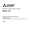
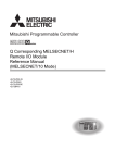
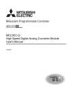
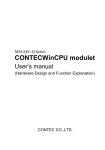
The MELSEC iQ-R series system is configured by mounting a module on a base unit.
A power supply module is mounted on the power supply slot at the left end of a main base unit and a CPU module is mounted
on the CPU slot at the right of the power supply slot. Modules other than the power supply module are mounted on the slots at
the right from the CPU slot.
(1) Main base unit
(2) Extension cable
(3) Extension base unit
(1)
(2)
(3)
(3)
(3)
16
1 SYSTEM CONFIGURATION
1.1 Overall Configuration
Maximum of seven
extension base units
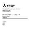
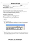
A MELSEC-Q series module and base unit can be used by connecting the RQ extension base unit in the
1
MELSEC iQ-R series system. ( Page 71 Connection Method for the Extension Base Unit)
MELSEC-Q series power supply modules, I/O modules, and intelligent function modules can be mounted on
the RQ extension base unit. ( Page 46 RQ extension base unit (for MELSEC-Q series modules))
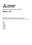
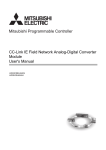
Using the RQ extension base unit makes it possible to reuse the existing Q series system as shown below.
MELSEC-Q series system
MELSEC iQ-R series system
MELSEC-Q series main base unit
MELSEC iQ-R series main base unit
OUT
5V
SG
POWER
CPU
I/O0
I/O1
I/O2
I/O3
I/O4
FG
MELSEC-Q series extension base unit
RQ extension base unit
MELSEC-Q series extension base unit
1 SYSTEM CONFIGURATION
1.1 Overall Configuration
17
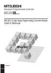
The network provides a seamless data communication across various levels, from the production control of all automation
down to a device such as a sensor.
Ethernet
CC-Link IE Controller Network
CC-Link IE Field
Network
SSCNET
CC-Link
• Without being aware of layers and boundaries of the network, access to the production control system, programmable
controllers, and other devices is possible in a seamless and identical manner. Device monitoring and data collection are
easy to perform from anywhere.
• CC-Link IE is the network with a large capacity and a high speed of 1 Gbps. The 1 Gbps broad bandwidth which is divided
into two parts, one for control communications and the other for information communications, ensures the time reliability of
control communications and achieves a real-time data collection, which is not allowed via TCP/IP.
• CC-Link is a globally standardized open field network. Flexible support for a multi-vendor environment allows a rich variety
of more than 1000 partner products to be connected to the MELSEC iQ-R series.
• SSCNET is a synchronous motion network that supports optical network and offers high speed and high reliability.
18
1 SYSTEM CONFIGURATION
1.1 Overall Configuration
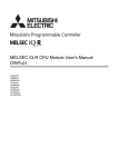
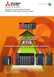
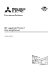
The system is classified into the following by the number of mounted CPU modules.
Single CPU system
1
This system controls an I/O module and intelligent function module using a CPU module mounted on a main base unit.
CPU module
Multiple CPU system
This system requires multiple CPU modules, and each module controls an I/O module and intelligent function module. (
Page 42 Control CPU)
Configure the multiple CPU system in the following cases.
• To execute the high-accuracy motion control by using a Motion CPU in a system
• To shorten the scan time of the entire system by distributing the control of an I/O module and intelligent function module
with multiple CPU modules
The CPU module is mounted on a main base unit only, and maximum of four CPU modules can be mounted. ( Page 27
Combinations of CPU modules on the multiple CPU system, Page 40 CPU Numbers)
For details on the multiple CPU system function, refer to the following.
MELSEC iQ-R CPU Module User's Manual (Application)
CPU module
1
2
3
4
1
1
2
3
4
1 SYSTEM CONFIGURATION
1.1 Overall Configuration
19
System configuration specifications, configuration devices, and
software
This chapter describes the overview of the MELSEC iQ-R series system configuration.
When using the C Controller module, refer to the following.
( MELSEC iQ-R C Controller Module User's Manual (Startup))
System configuration specifications
Item
Description
Mounting position of a module
Slot number 0 to 63
Maximum number of mountable
modules
Single CPU system
64*1*3
Multiple CPU system
57 to 63*1*2*3
Maximum number of extension base units
7*4
Overall extension cable distance
20m*5
*1
*2
*3
*4
*5
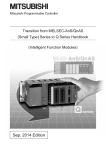
Mount modules within the range of the number of I/O points for the CPU module used. ( MELSEC iQ-R CPU Module User's Manual
(Startup))
The number of I/O points can be checked on the engineering tool. ( GX Works3 Operating Manual)
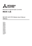
Modules can be mounted up to slot number 63 starting from the next slot where is mounted the CPU module at the right end. For
example, when four CPU modules are mounted on the CPU slot and slot number 0 to 2, the maximum number of mountable modules is
61.
The number of mountable modules includes the empty slots. Even if the number of I/O points is set zero point for an empty slot, the slot
is counted as one module.
This number is total of the extension base units, RQ extension base units, and MELSEC-Q series extension base units.
When a MELSEC-Q series module is used in the system, the overall cable distance is 13.2m.
CPU
0
1
2
3
4
5
6
7
8
9
10 11
12
13
14
15
16
17
18
19
20
21
22
23
Overall cable distance:
20m
Maximum of seven
extension base units
60
61
62
63
× × × × × × × ×
• Shaded areas show the power supply modules.
• CPU and the numbers in the above figure show the CPU slot and slot numbers.
• Modules cannot be mounted on .
20
1 SYSTEM CONFIGURATION
1.1 Overall Configuration
Lists of configuration devices
1
The following table lists configuration devices in the MELSEC iQ-R series system.
■MELSEC iQ-R series
Module
Base unit
Model
Main base unit
R35B, R38B, R312B
Extension base unit
R65B, R68B, R612B
RQ extension base unit
Extension cable
Power supply module
CPU module
Memory extension
R61P, R62P, R63P, R64P
Programmable controller CPU
R04CPU, R08CPU, R16CPU, R32CPU, R120CPU
Process CPU
R08PCPU, R16PCPU, R32PCPU, R120PCPU
Motion CPU
R16MTCPU, R32MTCPU
C Controller module
R12CCPU-V
SD memory card
NZ1MEM-2GBSD, NZ1MEM-4GBSD, NZ1MEM-8GBSD, NZ1MEM-16GBSD,
L1MEM-2GBSD, L1MEM-4GBSD
Extended SRAM Cassette
NZ2MC-1MBS, NZ2MC-2MBS, NZ2MC-4MBS, NZ2MC-8MBS, NZ2MC-8MBSE
Battery
I/O module
Intelligent function module
Blank cover module
*1
*2
RQ65B, RQ68B, RQ612B
RC06B, RC12B, RC30B, RC50B
Q6BAT, Q7BAT(-SET)
AC input module
RX10
DC input module
RX40C7, RX41C4, RX42C4
Contact output module
RY10R2
Transistor output module
RY40NT5P, RY41NT2P, RY42NT2P, RY40PT5P, RY41PT1P, RY42PT1P
I/O combined module
RH42C4NT2P
Analog-digital converter module
R60AD4, R60ADI8, R60ADV8
Channel isolated analog-digital
converter module
R60AD8-G, R60AD16-G*2
Digital-analog converter module
R60DA4, R60DAI8, R60DAV8
Channel isolated digital-analog
converter module
R60DA8-G, R60DA16-G*2
Simple motion module
RD77MS2, RD77MS4, RD77MS8, RD77MS16
Channel isolated RTD input module
R60RD8-G
Channel isolated thermocouple input
module
R60TD8-G
High-speed counter module
RD62P2, RD62D2, RD62P2E
Positioning module
RD75P2, RD75P4, RD75D2, RD75D4
Ethernet
RJ71EN71
CC-Link IE Field Network
RJ71GF11-T2, RJ71EN71
CC-Link IE Controller Network
RJ71GP21-SX, RJ71EN71*1
CC-Link
RJ61BT11
Serial communication
RJ71C24, RJ71C24-R2, RJ71C24-R4
RG60
When the CC-Link IE Controller Network function is used with the RJ71EN71, there are restrictions on the firmware version of the
programmable controller CPU and the RJ71EN71 ( Manual for each module). Note that the function cannot be used with the
Process CPU.
These modules take up two slots. When used with the programmable controller CPU, there are restrictions on the firmware version of
the programmable controller CPU ( MELSEC iQ-R CPU Module User's Manual (Application)).
1 SYSTEM CONFIGURATION
1.1 Overall Configuration
21
■MELSEC-Q series
The following table lists the MELSEC-Q series modules and extension cables which can be used in the MELSEC iQ-R series
system.
When a MELSEC-Q series module is used, refer to the following.
Page 102 How to Use MELSEC-Q Series Modules
Module
Base unit
Extension base unit
Q52B, Q55B, Q63B, Q65B, Q68B, Q612B
Q series large type extension base unit
Q55BL, Q65BL, Q68BL
Q series large type extension base unit (AnS series size)
Q55BLS, Q65BLS, Q68BLS, Q55BLS-D, Q65BLS-D, Q68BLS-D
Extension cable
QC05B, QC06B, QC12B, QC30B, QC50B, QC100B
Power supply module
Q61P, Q61P-A1, Q61P-A2, Q62P, Q63P, Q64P, Q64PN, Q61P-D
I/O module
22
Model
AC input module
QX10, QX10-TS, QX28
DC input module
QX40, QX40-TS, QX40-S1, QX41, QX41-S1, QX41-S2, QX42, QX42S1, QX70, QX71, QX72, QX80, QX80-TS, QX81, QX81-S2, QX82,
QX82-S1
DC high-speed input module
QX40H, QX70H, QX80H, QX90H
AC/DC input module
QX50
Contact output module
QY10, QY10-TS, QY18A
Triac output module
QY22
Transistor output module
QY40P, QY40P-TS, QY41P, QY42P, QY50, QY68A, QY70, QY71,
QY80, QY80-TS, QY81P, QY82P
Transistor high-speed output module
QY41H
I/O combined module
QH42P, QX48Y57, QX41Y41P
Interrupt module
QI60
Large type AC input module
QX11L, QX21L
Large type contact output module
QY11AL, QY13L
Large type triac output module
QY23L
Large type transistor output module
QY51PL
1 SYSTEM CONFIGURATION
1.1 Overall Configuration
Module
Intelligent function
module
Model
Analog-digital converter module
Q64AD, Q68ADV, Q68ADI
Channel isolated high resolution analog-digital converter
module
Q64AD-GH
channel isolated high resolution analog-digital converter
module (with signal conditioning function)
Q62AD-DGH
Channel isolated analog-digital converter module
Q68AD-G
Channel isolated analog-digital converter module (with
signal conditioning function)
Q66AD-DG
High speed analog-digital converter module
Q64ADH
Digital-analog converter module
Q62DA, Q62DAN, Q64DA, Q64DAN, Q68DAV, Q68DAVN, Q68DAI,
Q68DAIN
Channel isolated digital-analog converter module
Q62DA-FG, Q66DA-G
High speed digital-analog converter module
Q64DAH
Analog input/output module
Q64AD2DA
Load cell input module
Q61LD
Current transformer input module
Q68CT
RTD input module
Q64RD
Channel isolated RTD input module
Q64RD-G, Q68RD3-G
Thermocouple input module
Q64TD
Channel isolated thermocouple/micro voltage input
module
Q64TDV-GH
Channel isolated thermocouple input module
Q68TD-G-H01, Q68TD-G-H02
Temperature control module
Q64TCTTN, Q64TCRTN, Q64TCTTBWN, Q64TCRTBWN
Loop control module
Q62HLC
Multichannel high-speed counter module
QD63P6
4Mpps capable high-speed counter module
QD64D2
Channel isolated pulse input module
QD60P8-G
Multi function counter/timer module
QD65PD2
Positioning module
QD70P4, QD70P8, QD70D4, QD70D8, QD73A1
Positioning module with built-in counter function
QD72P3C3
MES interface module
QJ71MES96
Web server module
QJ71WS96
CC-Link/LT master module
QJ61CL12
AnyWire DB A20 master module
QJ51AW12D2
MODBUS/TCP interface module
QJ71MT91
Blank cover module
1
MODBUS interface module
QJ71MB91
FL-net (OPCN-2) interface module
QJ71FL71, QJ71FL71-T, QJ71FL71-B2, QJ71FL71-B5, QJ71FL71F01, QJ71FL71-T-F01, QJ71FL71-B2-F01, QJ71FL71-B5-F01
AS-i master module
QJ71AS92
Intelligent communication module
QD51, QD51-R24
DeviceNet master-slave module
QJ71DN91
AnyWireASLINK master module
QJ51AW12AL
Energy measuring module
QE81WH, QE84WH, QE81WH4W, QE83WH4W
Insulation monitoring module
QE82LG
Blank cover
QG60
Large type blank cover
QG69L
Q series large type blank cover (AnS series size)
QG69LS
1 SYSTEM CONFIGURATION
1.1 Overall Configuration
23
Software
The following software can be used for the MELSEC iQ-R series system. (Manual for each software used)
24
Software
Function and application
iQ Works Version 2
A package software integrated the various software such as a programmable controller, motion controller, and
GOT
GX Works3
A software for a system design, programming, debug, and maintenance of a programmable controller
1 SYSTEM CONFIGURATION
1.1 Overall Configuration
Communications between systems
1
The system that a programmable controller system communicates with other systems seamlessly can be configured by using
the network such as Ethernet and CC-Link IE.
Other series network can be connected by setting relay stations with multiple modules of difference network.
Ex.
Ethernet
CC-Link IE Controller Network
CC-Link IE Field Network
CC-Link
For the network module which can be used in the MELSEC iQ-R series system, refer to the following.
Page 21 Lists of configuration devices
1 SYSTEM CONFIGURATION
1.1 Overall Configuration
25
1.2
Precautions for System Configuration
This section describes precautions for configuring a system.
When using the C Controller module, refer to the following.
( MELSEC iQ-R C Controller Module User's Manual (Startup))
Modules having the restriction of the number of mountable
modules
This section describes modules having the restriction of the number of mountable modules.
MELSEC iQ-R series modules
Module
Model
Maximum number of mountable modules
Single CPU system
Multiple CPU system
CC-Link IE Controller Network-equipped
module
• RJ71GP21-SX
• RJ71EN71*4
8
32 (One CPU module can control eight
modules.)
CC-Link IE Field Network-equipped
master/local module*1
• RJ71GF11-T2
• RJ71EN71*3
8
32 (One CPU module can control eight
modules.)
CC-Link module*1*2
• RJ61BT11
8
32 (One CPU module can control eight
modules.)
*1
*2
*3
*4
There is no restriction when parameters are set using the dedicated instruction after "Program" in "System Parameter" is selected.
Use three network modules (RJ71GP21-SX, RJ71GF11-T2, and RJ71EN71 (when the CC-Link IE Field Network function is used)) or
less per CPU module at the automatic CC-Link startup.
There are the restrictions when the CC-Link IE Field Network function is used.
There are the restrictions when the CC-Link IE Controller Network function is used.
MELSEC-Q series modules
Module
Interrupt
Model
module*1
Input module*1*2
*1
*2
26
Maximum number of mountable modules
Single CPU system
Multiple CPU system
• QI60
1
4 (One CPU module can control one
module.)
•
•
•
•
1
4 (One CPU module can control one
module.)
QX40H
QX70H
QX80H
QX90H
There are the restrictions when parameters are not set in "I/O Assignment Setting" of "System Parameter". There is no restriction when
parameters are set in "I/O Assignment Setting".
There are the restrictions when the input module is shifted to an interrupt module by turning off the function selection switch (SW2).
1 SYSTEM CONFIGURATION
1.2 Precautions for System Configuration
Consideration for internal current consumption
1
Consider the system to be used so that the internal current consumption of the entire system is less than the rated output
current of the power supply module.
The total can be checked by using the engineering tool as follows.
The following window shows the check result.
Combinations of CPU modules on the multiple CPU system
Depending on what type of CPU module is set as CPU No.1, the CPU modules that can constitute the multiple CPU system
vary.
The following table shows the possible combination of CPU modules and the number of mountable modules in configuring the
multiple CPU system.
CPU module of CPU No.1
Programmable controller CPU
Number of mountable CPU modules of CPU No.2 or later
Programmable
controller CPU
Process CPU
Motion CPU
C Controller module
0 to 3
0 to 3*1
0 to 3
0 to 3
3*1
3*1
Process CPU
0 to
0 to 3
0 to
Motion CPU
Not supported
Not supported
Not supported
Not supported
C Controller module
0 to 3
Not supported
0 to 3
0 to 3
*1
Not supported
Under the multiple CPU system configuration, online module change is not permitted.
1 SYSTEM CONFIGURATION
1.2 Precautions for System Configuration
27
2
ASSIGNMENT FOR MODULES
This chapter describes a slot number, I/O number, CPU number, and assignment for a control CPU.
The assignment can be set by mounting modules on "Module Configuration" in the engineering tool.
Reading out system parameters and the system configuration also can set the assignment. ( GX Works3 Operating
Manual)
The following table lists the setting availability on "Module Configuration" or "System Parameter" for each setting item.
Item
Module Configuration
System Parameter
Base unit model
Power supply module model
Extension cable model
Module model
Module order
Module I/O number (Page 32 I/O Numbers of Modules)
Module status setting (Page 38 Module status setting)
Number of empty slots (Page 37 I/O number of an empty slot)
Control CPU (Page 42 Control CPU)
Number of slots of a base unit (Page 30 Setting for any slot numbers)
Number of points of a module
Use "Module Configuration" or "System Parameter" depending on the following application.
• Module Configuration: when the unique information of the module such as occupied points is used without
change
• System Parameter: when the number of slot for the base unit or the number of occupied points is changed
28
2 ASSIGNMENT FOR MODULES
2.1
Slot Numbers on a Base Unit
Slot numbers are assigned in serial number starting from the slot at the right of the CPU slot.
When a base unit is extended, a main base unit is assigned at the first level and extension base units are assigned at second
to seventh level.
2
The MELSEC-Q series extension base unit is required the extension level setting with the connector pin for the extension
level setting. ( Page 72 Setting method with connector pin for extension level setting)
CPU
0
5
1
6
2
7
3
8
4
9
Slot number
10
11
12
The module which occupied two slots is mounted, slot numbers for two modules are assigned.
2 ASSIGNMENT FOR MODULES
2.1 Slot Numbers on a Base Unit
29
Setting for any slot numbers
The number of slots for each base unit can be set the range of 1 to 12. Set the number of slots in the following cases.
• To secure slots to change into the base unit having the different number of slots for the future
• To not change the number of slots even if the base unit used in the existing system is changed
Navigation Window [System Parameter] [I/O Assignment Setting] [Base/Power/Extension Cable Setting]
■When the number of set slots is more than the number of actual slots
Slots corresponding to the set number are occupied, where the rest slots after a set of actually mounted slots are empty slots.
Ex.
Assuming that five slots are used in the base unit and eight slots are set as the number of slots, the remained three slots are
empty slots.
CPU
0
1
2
3
4
5
6
7
Empty slots
8
9
10
11
12
13
14
15
The number of empty slots can be changed in "Module Configuration", or "Setting of Points Occupied by
Empty Slot" in the system parameters. (Page 37 I/O number of an empty slot)
30
2 ASSIGNMENT FOR MODULES
2.1 Slot Numbers on a Base Unit
■When the number of set slots is less than the number of actual slots
Slots corresponding to the set number are occupied, where slots that are out of the set range are prohibited from mounting a
module, and the slot number is not assigned.
Ex.
Assuming that eight slots are used in the base unit and five slots are set as the number of slots, the excluded three slots are
2
prohibited from use.
CPU
0
1
2
3
4
Mounting prohibited
5
6
7
8
9
10
11
12
2 ASSIGNMENT FOR MODULES
2.1 Slot Numbers on a Base Unit
31
2.2
I/O Numbers of Modules
An I/O number is a hexadecimal assigned number for data communication with the CPU module through I/O modules and
intelligent function modules. Input and output are used for exchanging ON/OFF data. The head of an I/O number is "X" for
input, and "Y" for output.
(1)
(2)
(1) Input modules
(2) Output modules
(3)Intelligent function module
(3)
X
X
Y
Y
X/Y
16
16
16
16
32
Number of
points
00
to
0F
10
to
1F
20
to
2F
30
to
3F
40
to
5F
I/O number
I/O numbers starting from 0H, which is given to the module just right to the CPU module, are automatically assigned in
consecutive order.
In the extension base unit, assigned numbers start from the next number of the last I/O number in the main base unit.
Each slot in the base unit occupies I/O numbers corresponding to the points of a module mounted.
CPU
0
1
2
3
4
16
16
16
16
16
Number of points
00
to
0F
10
to
1F
20
to
2F
30
to
3F
40
to
4F
I/O number
5
6
7
8
9
10
11
12
16
16
16
16
32
32
16
16
50
to
5F
60
to
6F
70
to
7F
80
to
8F
90
to
AF
B0
to
CF
D0
to
DF
E0
to
EF
On placing a module in "Module Configuration" in the engineering tool, the I/O numbers are automatically assigned according
to the number of occupied points of the module.
Changing the module placement does not change the module I/O numbers once assigned.
32
2 ASSIGNMENT FOR MODULES
2.2 I/O Numbers of Modules
Open "System Monitor" in the engineering tool to check the mounted modules and their I/O numbers. ( GX
Works3 Operating Manual)
2
2 ASSIGNMENT FOR MODULES
2.2 I/O Numbers of Modules
33
Setting any desired I/O numbers
On placing a module in "Module Configuration", the I/O numbers are automatically assigned according to the number of
occupied points of the module. In the following cases, however, change the I/O numbers on a module-by-module basis:
• Even if the module is changed to a module that has a different number of occupied points, it seems desirable to eliminate
the need of the assignment modifications due to duplicated I/O numbers.
• When applying an already-existing program, I/O numbers are assigned to modules in just the same way in the program to
reduce the program modifications.
I/O numbers can be freely assigned beyond a boundary between the MELSEC iQ-R series and the MELSECQ series, being free from the restriction of assignment orders.
34
2 ASSIGNMENT FOR MODULES
2.2 I/O Numbers of Modules
32
16
16
16
16
Number of points
00
to
1F
40
to
4F
30
to
3F
80
to
8F
C0
to
CF
I/O number
16
16
16
16
16
16
16
16
50
to
5F
60
to
6F
70
to
7F
20
to
2F
90
to
9F
A0
to
AF
B0
to
BF
D0
to
DF
■Precautions
• The model name of a module needs to be set to the same model name of the mounted module.
• The CPU module that is not set as actually mounted denies access.
• For the module that permits changing the number of I/O points, set it in "I/O Assignment Setting" of "System Parameter".
• If the set number of I/O points differs from an actual mounting state, the modules operate as shown below:
Setting
Operation
Remarks
When the set number of points is less than
the number of I/O points of mounted
modules
The available number of points for the mounted I/O modules is
reduced to the set number of points.
Intelligent function modules does not
permit the setting of a fewer number of
points.
When the set number of points is more than
the number of I/O points of mounted
modules
The extra number of points over the actual number of points is not
used in the mounted I/O modules and intelligent function modules.
2
• Set "Module Configuration" as in the same system configuration actually used. Because the settings of the engineering tool
control the module operation, a setting that is different from the actual configuration may result in unintended operation.
• For an arbitrary setting of I/O numbers, setting the I/O numbers to all the modules is recommended. I/O numbers of a
module that is not set in the engineering tool are assigned following the I/O numbers of the module already set, which can
cause duplication of I/O numbers.
Ex.
Duplication of I/O numbers as a result of setting the I/O numbers arbitrarily up to No.4 slot
• Engineering tool
For the start I/O number, set 40 to a module of slot
No.3 and set 30 to a module of slot No.4.
2 ASSIGNMENT FOR MODULES
2.2 I/O Numbers of Modules
35
• Mounting state
CPU
I/O numbers in slot No.5, which is not set in the
engineering tool, are assigned following the I/O
numbers in slot No.4, which result in duplication of I/
O numbers.
0
1
2
3
4
16
16
16
16
16
Number of points
00
to
0F
10
to
1F
20
to
2F
40
to
4F
30
to
3F
I/O number
5
6
7
8
9
10
11
12
16
40
to
4F
Set the I/O numbers in slot No.5 to non-duplicated
numbers by using the engineering tool.
• To set the module reserved for future use, or when an already set module is not to be mounted, perform the module status
setting. (Page 38 Module status setting)
36
2 ASSIGNMENT FOR MODULES
2.2 I/O Numbers of Modules
I/O number of an empty slot
An empty slot is a slot where a module is not mounted, and occupies 16 points by default.
Although this slot is empty, it allows setting up the I/O number and the number of points, both of which are reserved for future
use.
2
The number of points can be changed for all empty slots at once by selecting the CPU module in "Module Configuration" as
shown below.
2 ASSIGNMENT FOR MODULES
2.2 I/O Numbers of Modules
37
Module status setting
The module status setting makes it possible to set the module status such as reserved status and disabled status, interpreting
a configured module in the engineering tool as an empty slot.
The following table shows the application of the module status setting.
Status
Application
Reserved status
• To operate the module that is included in the module configuration of the engineering tool, but without actually
mounting the module.
• To allocate the I/O numbers of a module reserved for future use
Disabled status
• To make an actually mounted module stop the operation
The change of the parameter settings is not reflected in the module where the module status setting has been performed.
In addition, the following operations have no effect on the module where the module status setting has been performed:
• Setting a remote password
• Executing a program that accesses the module itself
Perform the module status setting as shown below. ( GX Works3 Operating Manual)
Ex.
To operate the module that is included in the module configuration of the engineering tool, but without actually mounting the
module
• Module configuration
On performing the module status setting, the module becomes a light color,
interpreted as an empty slot.
• Mounting state
Writing the module configuration to the programmable controllers allows
operation even without mounting modules actually.
Empty
38
2 ASSIGNMENT FOR MODULES
2.2 I/O Numbers of Modules
Assigning I/O numbers in the slave station
Network systems such as CC-Link IE Field Network can be controlled by assigning input "X" and output "Y", which are in the
device of the CPU module, to the I/O modules and intelligent function modules in the slave station.
Ex.
2
Controlling a module mounted on the head module part on CC-Link IE Field Network
(1) Master station
(2) Slave station
(3) Head module
(1)
16
16
16
16
20
to
2F
30
to
3F
40
to
4F
50
to
5F
CC-Link IE Field Network
(2)
16
(3)
16
1000 1010
to
to
100F 101F
■Available I/O numbers
In the slave station, assign the I/O numbers following the I/O numbers assigned to the modules in the master station.
■Precautions
• Avoid duplication of I/O numbers between the refresh destination (device on the CPU module side) on CC-Link IE Field
Network and the CC-Link remote station.
• If there is a possibility of adding I/O modules and intelligent function modules to the CPU module side, set the reserved I/O
numbers to be added.
Input/output (X/Y)
X/Y0
I/O numbers used for an I/O module or
intelligent function module
·
X/Y3FF
X/Y400
·
For the future extension
X/YFFF
X/Y1000
For a CC-Link IE Field
Network slave station
Empty
·
For a CC-Link
remote station
I/O numbers that can be used for a slave station
X/Y2FFF
2 ASSIGNMENT FOR MODULES
2.2 I/O Numbers of Modules
39
2.3
CPU Numbers
CPU numbers refer to the numbers for identifying the CPU modules on the multiple CPU system.
The CPU module mounted on the CPU slot in the base unit is CPU No.1. CPU No.2, CPU No.3, and CPU No.4 are
sequentially assigned to the CPU modules on the right side of CPU No.1.
CPU
0
1
2
1
2
3
4
3
4
Slot number
CPU number
The multiple CPU system configuration requires the specification of mounted CPU modules, so that the I/O numbers are
assigned to the CPU modules as well. Assigned I/O numbers are fixed by each CPU number as shown below:
CPU number
Start I/O number of the CPU module
CPU No.1
3E00H
CPU No.2
3E10H
CPU No.3
3E20H
CPU No.4
3E30H
Reservation setting of the CPU module
The reservation setting of the CPU modules excluding CPU No.1 is possible to reserve CPU numbers for the CPU modules to
be mounted in the future. (Page 38 Module status setting)
However, if an actually mounted CPU module is set to the disabled status, the module is not to be interpreted as an empty
slot.
• Module configuration
Perform the module reservation setting on the CPU module at slot number 1.
• Mounting state
A reserved CPU number of the CPU module is assigned even without actually
mounting the CPU module.
1
40
2
3
4
2 ASSIGNMENT FOR MODULES
2.3 CPU Numbers
The CPU module can be mounted on the CPU slot and the slot number 0 to 6, where the opening slot between CPU modules
can be reserved as an empty slot. I/O modules and intelligent function modules, however, cannot be mounted on the opening
slot between CPU modules.
2
1
2
3
1
4
CPU number
2 ASSIGNMENT FOR MODULES
2.3 CPU Numbers
41
2.4
Control CPU
The control CPU refers to the CPU module that controls I/O modules and intelligent function modules.
The multiple CPU system configuration requires setting of the control CPU that controls modules. If the control CPU is not set,
CPU No.1 controls all the modules.
CPU module
1
2
3
4
1
1
2
3
4
Set the control CPU for each module in "Module Configuration".
42
2 ASSIGNMENT FOR MODULES
2.4 Control CPU
3
PART NAMES
3.1
Power Supply Module
This section describes the part names of the power supply module. (The R62P is used as an example.)
3
(1)
(2)
(8)
(3)
(6)
(4)
(5)
(7)
No.
Name
Description
(1)
POWER LED
Indicates the operating status of the power supply module.
On: Normal operation
Off: Power-off, power failure, or hardware failure ( MELSEC iQ-R CPU Module User's Manual
(Application))
(2)
ERR contact
Turns on when the entire system operates normally. (M4 screw)
This contact turns off (opens) when the power is not supplied, a stop error (including reset) occurs in the
CPU module, or the fuse is blown.
In a multiple CPU system, the contact turns off when a stop error occurs in any of the CPU modules.
The contact is off at all times when the module is mounted on an extension base unit.
(3)
FG terminal*1
A functional ground terminal connected to the shield pattern of the printed circuit board (M4 screw)
(4)
LG
terminal*1
(5)
Power input terminal
(6)
Terminal cover
A protective cover for the terminal block
(7)
Production information marking
Shows the production information (16 digits) of the module.
(8)*2
+24V and 24G terminals
Used for a device that requires a supply of 24VDC (M3.5 screw).
The power is supplied to a device through the external wiring.
*1
*2
A functional ground terminal for the power supply input filter. For AC input, the terminal has one-half the
potential of the input voltage. (M4 screw)
A power input terminal for the power supply module. The input power supply differs depending on a power
supply module. (M4 screw) ( Page 49 Performance Specifications of Power Supply Module)
Individually ground the FG and LG terminals with a ground resistance of 100 ohms or less.
The R62P only has these terminals.
3 PART NAMES
3.1 Power Supply Module
43
3.2
Base Unit
Main base unit
This section describes the part names of the main base unit. (The R312B is used as an example.)
(1) (2)
(5)
(4)
(8)
(3)
(7)
(6)
44
No.
Name
Description
(1)
Extension cable connector (OUT)
A connector for connecting to an extension base unit. A MELSEC iQ-R series extension cable is connected
here.
When no cable is connected, attach the supplied extension connector cover to prevent entry of foreign
matter such as dust.
(2)
Extension connector cover
A protective cover for the extension cable connector
(3)
Module connector
A connector for mounting MELSEC iQ-R series modules.
Attach the supplied connector cover or the blank cover module (RG60) to the connector(s) where no module
is mounted to prevent entry of foreign matter such as dust.
(4)
Module fixing hole
A screw hole to fix a module to the base unit (M312 screw)
(5)
Base unit installation hole
A hole to install the base unit to a control panel (M4 screw)
(6)
DIN rail adapter mounting hole
A hole to mount a DIN rail adapter
(7)
Guide
A guide to mount a module to the base unit
(8)
Production information marking
Shows the production information (16 digits) of the base unit.
3 PART NAMES
3.2 Base Unit
Extension base unit
This section describes the part names of the extension base unit. (The R612B is used as an example.)
(1) (3)
(6)
(2)
(5)
3
(9)
(4)
(8)
(7)
No.
Name
Description
(1)
Extension cable connector (IN)
A connector for connecting to a base unit (upper level). A MELSEC iQ-R series extension cable is
connected here.
(2)
Extension cable connector (OUT)
A connector for connecting to a base unit (lower level). A MELSEC iQ-R series extension cable is connected
here.
When no cable is connected, attach the supplied extension connector cover to prevent entry of foreign
matter such as dust.
(3)
Extension connector cover
A protective cover for the extension cable connector
(4)
Module connector
A connector for mounting MELSEC iQ-R series modules. The CPU module cannot be mounted on an
extension base unit.
Attach the supplied connector cover or the blank cover module (RG60) to the connector(s) where no module
is mounted to prevent entry of foreign matter such as dust.
(5)
Module fixing hole
A screw hole to fix a module to the base unit (M312 screw)
(6)
Base unit installation hole
A hole to install the base unit to a control panel (M4 screw)
(7)
DIN rail adapter mounting hole
A hole to mount a DIN rail adapter
(8)
Guide
A guide to mount a module to the base unit
(9)
Production information marking
Shows the production information (16 digits) of the base unit.
3 PART NAMES
3.2 Base Unit
45
RQ extension base unit (for MELSEC-Q series modules)
This section describes the part names of the extension base unit. (The RQ612B is used as an example.)
(1) (3)
(6)
(2)
(5)
(8)
(4)
(7)
46
No.
Name
Description
(1)
Extension cable connector (IN)
A connector for connecting to a MELSEC iQ-R series base unit (upper level). A MELSEC iQ-R series
extension cable is connected here.
(2)
Extension cable connector (OUT)
A connector for connecting to a MELSEC Q series base unit (lower level). A MELSEC Q series extension
cable is connected here.
When no cable is connected, attach the supplied extension connector cover to prevent entry of foreign
matter such as dust.
(3)
Extension connector cover
A protective cover for the extension cable connector
(4)
Module connector
A connector for mounting MELSEC-Q series modules. The CPU module cannot be mounted on an
extension base unit.
Attach the supplied connector cover or the blank cover module (QG60) to the connector(s) where no module
is mounted to prevent entry of foreign matter such as dust.
(5)
Module fixing hole
A screw hole to fix a module to the base unit (M312 screw)
(6)
Base unit installation hole
A hole to install the base unit to a control panel (M4 screw)
(7)
DIN rail adapter mounting hole
A hole to mount a DIN rail adapter
(8)
Production information marking
Shows the production information (16 digits) of the base unit.
3 PART NAMES
3.2 Base Unit
3.3
SD Memory Card
This section describes the part names of the SD memory card. (The NZ1MEM-16GBSD is used as an example.)
(1)
3
No.
Name
Description
(1)
Write protect switch
Prevents the data in the card from being erased or modified by setting this switch to the LOCK position.
3 PART NAMES
3.3 SD Memory Card
47
4
SPECIFICATIONS
4.1
General Specifications
This chapter describes the general specifications of the modules used.
Item
Specifications
Operating ambient temperature
0 to 55
Storage ambient temperature
-25 to 75
Operating ambient humidity
5 to 95%RH, non-condensing
Storage ambient humidity
5 to 95%RH, non-condensing
Vibration resistance
Compliant with
JIS B 3502 and
IEC 61131-2
Frequency
Constant
acceleration
Half amplitude
Sweep count
Under
intermittent
vibration
5 to 8.4Hz
3.5mm
8.4 to 150Hz
9.8m/
10 times each in
X, Y, and Z
directions
Under
continuous
vibration
Shock resistance
*1
Overvoltage category
Inside a control panel
*2
or less
2 or less
Equipment class
Class 1
*3
*4
*5
48
No corrosive gases*4, flammable gases, less conductive dust
Pollution degree*3
*2
1.75mm
0 to 2000m*5
Installation location
*1
4.9m/
Compliant with JIS B 3502 and IEC 61131-2 (147m/, 3 times each in X, Y, and Z bidirections)
Operating atmosphere
Operating altitude
5 to 8.4Hz
8.4 to 150Hz
Do not use or store the programmable controller under pressure higher than the atmospheric pressure of altitude 0m. Doing so may
cause malfunction. When using the programmable controller under pressure, please consult your local Mitsubishi representative.
This indicates the section of the power supply to which the equipment is assumed to be connected between the public electrical power
distribution network and the machinery within premises. Category applies to equipment for which electrical power is supplied from
fixed facilities. The surge voltage withstand level for up to the rated voltage of 300V is 2500V.
This index indicates the degree to which conductive material is generated in terms of the environment in which the equipment is used.
Pollution degree 2 is when only non-conductive pollution occurs. A temporary conductivity caused by condensing must be expected
occasionally.
Use the special coated products which comply with the IEC 60721-3-3 3C2 in the environment with the corrosive gases. For details on
the special coated products, please consult your local representative.
When the programmable controller is used at altitude above 2000m, the withstand voltage performance and the upper limit of the
operating ambient temperature decrease. Please consult your local Mitsubishi representative.
4 SPECIFICATIONS
4.1 General Specifications
4.2
Performance Specifications of Power Supply
Module
This section describes the performance specifications of the power supply module.
Item
AC input power supply module
R61P
Input power supply voltage
R62P
DC input power
supply module
R64P
R63P
100 to 240VAC
(85 to 264VAC)
24VDC
(15.6 to 31.2VDC)
Input frequency
50/60Hz5%
Input voltage distortion factor
Within 5%
Maximum input apparent power
130VA
Maximum input power
50W
Inrush current
20A, 8ms or less
100A, 1ms or less
Rated output current
Overcurrent protection
Overvoltage protection
120VA
160VA
5VDC
6.5A
3.5A
9A
6.5A
24VDC
0.6A
5VDC
7.1A or higher
3.8A or higher
10.0A or higher
7.1A or higher
24VDC
0.66A or higher
5VDC
5.5 to 6.5V
Efficiency
76% or more
70% or more
Allowable momentary power failure time
Within 20ms
Within 10ms
Withstand voltage
2300VACrms per minute (altitude 0 to 2000m),
between all input & LG terminals and all output & FG terminals
510VAC per minute
(altitude 0 to 2000m),
between primary
terminal and 5VDC
terminal
Insulation resistance
10M or higher between all input & LG terminals and all output & FG terminals, between all input
terminals and LG terminal, between all output terminals and FG terminal (500VDC insulation
resistance tester)
Noise immunity
• Noise voltage 1500Vp-p, noise width 1s, noise frequency 25 to 60Hz (noise simulator condition)
• Noise immunity test IEC 61000-4-4: 2kV
Fuse
Contact output section
Built-in (user-unchangeable)
Application
ERR contact
Rated switching
voltage/current
24VDC, 0.5A
Minimum switching
load
5VDC, 1mA
Response time
Offon: 10ms or less
Onoff: 12ms or less
Life
Mechanical: 20 million times or more
Electrical: Rated switching voltage/current, 100 thousand times or more
Surge suppressor
None
Fuse
None
Terminal screw size
M4 (M3.5 for +24V and 24G terminals of the R62P)
Applicable wire size
0.75 to 2
Applicable solderless terminal
RAV1.25-4, RAV2-4, thickness of 0.8mm or less, up to two solderless terminal connections per
terminal
(for the +24V and 24G terminals of the R62P: RAV1.25-3.5, RAV2-3.5, thickness of 0.8mm or less,
up to two solderless terminal connections per terminal)
Applicable tightening torque
M4 screw: 1.02 to 1.38Nm
M3.5 screw: 0.66 to 0.89Nm
External dimensions
Weight
4
Height
106mm (Base unit mounting side: 98mm)
Width
54.6mm
Depth
110mm
0.41kg
0.45kg
0.46kg
0.41kg
4 SPECIFICATIONS
4.2 Performance Specifications of Power Supply Module
49
Detailed explanation of items
■Input power supply voltage
Input power supply voltage is a voltage required for the power supply module to operate normally. If the voltage is out of the
specified range, an error is detected and the system may stop.
■Inrush current
Inrush current is the maximum, instantaneous input current drawn into the circuits immediately after power-on.
If power is supplied to the system immediately after shut-off, an inrush current of more than the specified value may flow.
Wait for five seconds or more after shut-off, and supply power to the system again.
When selecting a fuse or breaker for the external circuit, consider blowouts, sensing property, and specified value of inrush
current.
■Overcurrent protection
The function of this protection is to shut off the circuit to stop the system if a current exceeding the specification value flows
into a 5VDC or 24VDC circuit.
With overcurrent protection activated, the LED of the power supply module turns off or lights dim green due to a voltage drop.
To restart the system, shut off the power and eliminate the cause of the problem, such as insufficient current or short-circuit.
After the cause is eliminated, wait for a few minutes, and supply power to the system again. When the output current is back
to normal, the system starts initially.
■Overvoltage protection
The function of this protection is to shut off the circuit to stop the system if an overvoltage exceeding the specified value is
applied to a 5VDC circuit.
With overvoltage protection activated, the POWER LED of the power supply module turns off.
To restart the system, shut off the power, wait for a few minutes, and supply power to the system again. Then, the system
starts initially.
If the system does not restart and the POWER LED remains off, replace the power supply module.
■Allowable momentary power failure time
The system detects an input voltage down and stops its operation when a momentary power failure occurs. Allowable
momentary power failure time is a period of time that the system can continue its operation even after the power failure.
If power fails exceeding this period of time, the system can either continue its operation or start initially, depending on the load
of the power supply module. When the system continues its operation, the operation will be the same as that of the system
returned within the allowable momentary power failure time.
50
4 SPECIFICATIONS
4.2 Performance Specifications of Power Supply Module
Selecting the power supply module
The power supply module should be selected in accordance with the total current consumption of the power supply target
base unit, CPU module(s), I/O module(s), and intelligent function module(s).
Select the power supply module so that the current consumption of the base unit does not exceed the rated output current of
the power supply module mounted on the base unit.
For the internal current consumption (5VDC) of the base unit and CPU module, refer to the following.
• Base unit ( Page 52 Performance Specifications of Base Unit)
• CPU module ( MELSEC iQ-R CPU Module User's Manual (Startup))
For the internal current consumption (5VDC) of each module, refer to the manual for the module used.
For devices obtained by a user, such as an external power supply (24VDC) and breaker, refer to the manual for the device
4
used.
■When MELSEC-Q series modules are connected
Select the power supply module so that the current consumption of each extension base unit does not exceed the rated
output current of the power supply module mounted on each extension base unit.
When the extension base unit (type requiring no power supply module) (Q5B) is used, power is supplied from the power
supply module mounted on the RQ extension base unit. Select the power supply module so that the total current consumption
of the modules on the RQ extension base unit and the Q5B does not exceed the rated output current of the power supply
module mounted on the RQ extension base unit. (Page 27 Consideration for internal current consumption)
The current consumption can be checked using the engineering tool (Power Supply Capacity and I/O Points).
4 SPECIFICATIONS
4.2 Performance Specifications of Power Supply Module
51
4.3
Performance Specifications of Base Unit
This section describes the performance specifications of the base unit.
Main base unit
Item
R35B
R38B
R312B
Number of mountable I/O
modules
5
8
12
DIN rail adapter model
R6DIN1
Internal current consumption
(5VDC)
0.58A
0.71A
0.88A
M4 screw hole or 4.5 hole (for M4 screw)
Mounting hole size
External dimensions
Height
101mm
Width
245mm
Depth
32.5mm
Weight
0.41kg
328mm
439mm
0.55kg
0.72kg
Extension base unit
Item
R65B
R68B
R612B
Number of mountable I/O
modules
5
8
12
DIN rail adapter model
R6DIN1
Internal current consumption
(5VDC)
0.70A
0.81A
0.92A
Mounting hole size
M4 screw hole or 4.5 hole (for M4 screw)
External dimensions
Height
101mm
Width
245mm
Depth
32.5mm
Weight
0.41kg
328mm
439mm
0.55kg
0.73kg
Extension cable
Item
RC06B
RC12B
RC30B
RC50B
Length
0.6m
1.2m
3.0m
5.0m
Weight
0.15kg
0.21kg
0.40kg
0.60kg
RQ extension base unit (for MELSEC-Q series modules)
Item
RQ65B
RQ68B
RQ612B
Number of mountable I/O
modules
5
8
12
DIN rail adapter model
Q6DIN2
Q6DIN1
Internal current consumption
(5VDC)
0.28A
0.31A
M4 screw hole or 4.5 hole (for M4 screw)
Mounting hole size
External dimensions
Weight
Height
98mm
Width
245mm
Depth
44.1mm
0.32kg
328mm
439mm
0.41kg
0.55kg
For the specifications of MELSEC-Q series extension cables, refer to the following.
QCPU User's Manual (Hardware Design, Maintenance and Inspection)
52
0.32A
4 SPECIFICATIONS
4.3 Performance Specifications of Base Unit
4.4
Performance Specifications of SD Memory Card
This section describes the performance specifications of the SD memory card.
Item
NZ1MEM-2GBSD
NZ1MEM-4GBSD
Type
SD
SDHC
Capacity
2G bytes
4G bytes
Number of writings
60000 times
100000 times
External dimensions
Height
32mm
Width
24mm
Depth
2.1mm
Weight
NZ1MEM-8GBSD
NZ1MEM16GBSD
8G bytes
16G bytes
4
2g
For details on the performance specifications of the L1MEM-2GBSD and L1MEM-4GBSD, refer to the following.
QCPU User's Manual (Hardware Design, Maintenance and Inspection)
Handling precautions
• The operation of the SD memory cards manufactured by Mitsubishi (NZ1MEM-GBSD) has been tested on the MELSEC
iQ-R series modules. An SD memory card manufactured by others*1 may cause corruption of data in the SD memory card,
a shutdown of the system, or other malfunctions.
• When inserted into a compatible module, the SD memory card manufactured by Mitsubishi already conforms to IEC 611312.
• An SD memory card of the card type SDHC can be used only with products that bear the SDHC logo on the surface or in
the user’s manual. Be aware that this type of card cannot be used with products that support only the card type SD.
• All SD memory cards to be used in the CPU module need to be formatted. When purchased, an SD memory card is
unformatted; thus, before use, insert the SD memory card into the CPU module to format it using the engineering tool. Do
not attempt to format an SD memory card on a personal computer. ( GX Works3 Operating Manual)
• While access to an SD memory card is in progress, performing a power-off or reset, or ejecting the SD memory card may
cause corruption of data in the SD memory card. If the CARD ACCESS LED is on, be sure to deactivate the access to the
SD memory card with the SD memory card access control switch, and then perform a power-off or reset, or eject the SD
memory card. The use of the SD memory card can be disabled by SM606 (SD memory card forced disable instruction) and
the disabled status can be checked by SM607 (SD memory card forced disable status flag).
• The recommended way to protect precious data is to make a backup regularly on other media such as CDs and DVDs.
*1
For the SD memory cards that are commercially available and connectable, refer to the following. Before use, properly verify that the
control performance on the system is free from a problem.
TECHNICAL BULLETIN No.FA-A-0078
Precautions
If the CPU module is powered off or reset, or the SD memory card is removed while the card is being accessed as below, data
on the SD memory card may corrupt.
• During saving data in the buffer memory to an SD memory card by using the data logging function
• During the folder delete by "User Data Operation" in the engineering tool
In the above case, the SD memory card diagnostics such as the file system check and restoration) is performed at powering
off the system or the reset clear.
Note that the data may be not restored because of the file system status.
Diagnosing the SD memory card takes the following times (assuming that 10000 files (100K bytes) are stored in the SD
memory card).*1*2
• NZ1MEM-2GBSD: approximately 7 seconds NZ1MEM-4GBSD: approximately 8 seconds NZ1MEM-8GBSD:
approximately 9 seconds NZ1MEM-16GBSD: approximately 10 seconds
*1
*2
The more the number of files in the SD memory card, the longer the diagnosis time.
When the CPU module is in connection with an external device, running the CPU module and the external device simultaneously can
cause communication time-out on the external devise side.
4 SPECIFICATIONS
4.4 Performance Specifications of SD Memory Card
53
4.5
Performance Specifications of Battery
This section describes the performance specifications of the battery used for the CPU module.
Q7BAT*1
Item
Q6BAT
Type
Manganese dioxide lithium primary battery
Initial voltage
3.0V
Nominal current
1800mAh
Battery life when not used
Approximately 5 years (room temperature)
5000mAh
Lithium content
0.52g
Application
To hold backup data and clock data
*1
1.55g
The Q7BAT-SET includes a battery holder.
Battery life
For the programmable controller CPU
There are two types of values for describing a battery life: actual service value and guaranteed value.
■Actual service value (reference value)
The actual service value (reference value) refers to the battery life estimated based on our actual measurement value under a
storage ambient temperature of 40. This value is intended for reference only because it varies depending on the
characteristics of the components.
• Actual service value of the Q6BAT and Q7BAT: 43800 hours (5.00 years)
■Guaranteed value
The guaranteed value refers to the battery life at 70 where we can give a guarantee, the value of which is estimated based
on the characteristics of the memory device, provided by the components manufacturer, under a storage ambient temperature
of -25 to 75 (an operating ambient temperature of 0 to 55).
Here are the guaranteed values of the Q6BAT and Q7BAT.
Whether to use an
extended SRAM
cassette
Power-on time
ratio*1
Guaranteed value with the R04CPU used
Guaranteed value with the R08CPU,
R16CPU, R32CPU, or R120CPU used
Not used
0%
Q6BAT
Q7BAT
Q6BAT
Q7BAT
31700 hours (3.61
years)
43800 hours (5.00
years)
30600 hours (3.49
years)
43800 hours (5.00
years)
30%
43800 hours (5.00
years)
50 to 100%
Used
(1MB type)
43800 hours (5.00
years)
0%
22000 hours (2.51
years)
21500 hours (2.45
years)
30%
31400 hours (3.58
years)
30700 hours (3.50
years)
50%
43800 hours (5.00
years)
43000 hours (4.90
years)
70 to 100%
Used
(2MB type)
54
43700 hours (4.98
years)
43800 hours (5.00
years)
0%
19600 hours (2.23
years)
19100 hours (2.18
years)
43100 hours (4.92
years)
30%
28000 hours (3.19
years)
27200 hours (3.10
years)
43800 hours (5.00
years)
50%
39200 hours (4.47
years)
38200 hours (4.36
years)
70 to 100%
43800 hours (5.00
years)
43800 hours (5.00
years)
4 SPECIFICATIONS
4.5 Performance Specifications of Battery
Whether to use an
extended SRAM
cassette
Power-on time
ratio*1
Guaranteed value with the R04CPU used
Q6BAT
Q7BAT
Q6BAT
Q7BAT
Used
(4MB type)
0%
15300 hours (1.74
years)
39600 hours (4.52
years)
15000 hours (1.71
years)
36200 hours (4.13
years)
30%
21800 hours (2.48
years)
43800 hours (5.00
years)
21400 hours (2.44
years)
43800 hours (5.00
years)
50%
30600 hours (3.49
years)
30000 hours (3.42
years)
70 to 100%
43800 hours (5.00
years)
43800 hours (5.00
years)
0%
10100 hours (1.15
years)
26900 hours (3.07
years)
10000 hours (1.14
years)
24800 hours (2.83
years)
30%
14400 hours (1.64
years)
38400 hours (4.38
years)
14200 hours (1.62
years)
35400 hours (4.04
years)
50%
20200 hours (2.30
years)
43800 hours (5.00
years)
20000 hours (2.28
years)
43800 hours (5.00
years)
70%
33600 hours (3.83
years)
33300 hours (3.80
years)
100%
43800 hours (5.00
years)
43800 hours (5.00
years)
Used
(8MB type)
*1
Guaranteed value with the R08CPU,
R16CPU, R32CPU, or R120CPU used
4
The power-on time ratio indicates the ratio of the programmable controller power-on time to 24 hours. (If the total power-on time is 12
hours, the ratio will be 50%. If the total power-on time is 6 hours, the ratio will be 25%.)
4 SPECIFICATIONS
4.5 Performance Specifications of Battery
55
For the Process CPU
There are two types of values for describing a battery life: actual service value and guaranteed value.
■Actual service value (reference value)
The actual service value (reference value) refers to the battery life estimated based on our actual measurement value under a
storage ambient temperature of 40. This value varies depending on the characteristics and variation of the components,
and should be referred to as a reference value.
Whether to use an
extended SRAM
cassette
Power-on time
ratio*1
Not used,
Used (1MB type),
Used (2MB type)
0 to 100%
Used
(4MB type)
0%
42200 hours (4.81
years)
30 to 100%
43800 hours (5.00
years)
Used
(8MB type)
Used
(ECC-capable 8MB
type)
Actual service value with the R08PCPU or
R16PCPU used
Actual service value with the R32PCPU or
R120PCPU used
Q6BAT
Q7BAT
Q6BAT
Q7BAT
43800 hours (5.00
years)
43800 hours (5.00
years)
43800 hours (5.00
years)
43800 hours (5.00
years)
0%
33700 hours (3.84
years)
31700 hours (3.61
years)
30 to 100%
43800 hours (5.00
years)
43800 hours (5.00
years)
0%
24000 hours (2.73
years)
23000 hours (2.62
years)
30%
34200 hours (3.90
years)
32800 hours (3.74
years)
50 to 100%
43800 hours (5.00
years)
43800 hours (5.00
years)
■Guaranteed value
The guaranteed value refers to the battery life at 70 where we can give a guarantee, the value of which is estimated based
on the characteristics of the memory device, provided by the components manufacturer, under a storage ambient temperature
of -25 to 75 (an operating ambient temperature of 0 to 55).
Here are the guaranteed values of the Q6BAT and Q7BAT.
Whether to use an
extended SRAM
cassette
Power-on time
ratio*1
Guaranteed value with the R08PCPU or
R16PCPU used
Guaranteed value with the R32PCPU or
R120PCPU used
Q6BAT
Q7BAT
Q6BAT
Q7BAT
Not used
0%
24400 hours (2.78
years)
43800 hours (5.00
years)
17300 hours (1.97
years)
39900 hours (4.55
years)
30%
34800 hours (3.97
years)
24700 hours (2.81
years)
43800 hours (5.00
years)
50%
43800 hours (5.00
years)
34600 hours (3.94
years)
70 to 100%
Used
(1MB type)
56
43800 hours (5.00
years)
0%
18100 hours (2.06
years)
41500 hours (4.73
years)
13900 hours (1.58
years)
34200 hours (3.900
years)
30%
25800 hours (2.94
years)
43800 hours (5.00
years)
19800 hours (2.26
years)
43800 hours (5.00
years)
50%
36200 hours (4.13
years)
27800 hours (3.17
years)
70 to 100%
43800 hours (5.00
years)
43800 hours (5.00
years)
4 SPECIFICATIONS
4.5 Performance Specifications of Battery
Whether to use an
extended SRAM
cassette
Power-on time
ratio*1
Guaranteed value with the R08PCPU or
R16PCPU used
Q6BAT
Q7BAT
Q6BAT
Q7BAT
Used
(2MB type)
0%
16400 hours (1.87
years)
38500 hours (4.39
years)
12900 hours (1.47
years)
32000 hours (3.65
years)
30%
23400 hours (2.67
years)
43800 hours (5.00
years)
18400 hours (2.10
years)
43800 hours (5.00
years)
50%
32800 hours (3.74
years)
15800 hours (2.94
years)
70%
43800 hours (5.00
years)
43000 hours (4.90
years)
100%
Used
(4MB type)
43800 hours (5.00
years)
0%
13300 hours (1.51
years)
33300 hours (3.80
years)
10900 hours (1.24
years)
27000 hours (3.08
years)
30%
19000 hours (2.16
years)
43800 hours (5.00
years)
15500 hours (1.76
years)
38500 hours (4.39
years)
50%
26600 hours (3.03
years)
21800 hours (2.48
years)
43800 hours (5.00
years)
70%
43800 hours (5.00
years)
36300 hours (4.14
years)
100%
Used
(8MB type)
Used
(ECC-capable 8MB
type)
*1
Guaranteed value with the R32PCPU or
R120PCPU used
4
43800 hours (5.00
years)
0%
9200 hours (1.05 years)
22900 hours (2.61
years)
8000 hours (0.91 years)
19800 hours (2.26
years)
30%
13100 hours (1.49
years)
32700 hours (3.73
years)
11400 hours (1.30
years)
28200 hours (3.21
years)
50%
18400 hours (2.10
years)
43800 hours (5.00
years)
16000 hours (1.82
years)
39600 hours (4.52
years)
70%
30600 hours (3.49
years)
26600 hours (3.03
years)
43800 hours (5.00
years)
100%
43800 hours (5.00
years)
43800 hours (5.00
years)
0%
6100 hours (0.69 years)
15100 hours (1.72
years)
5500 hours (0.62 years)
13700 hours (1.56
years)
30%
8700 hours (0.99 years)
21500 hours (2.45
years)
7800 hours (0.89 years)
19500 hours (2.22
years)
50%
12200 hours (1.39
years)
30200 hours (3.44
years)
11000 hours (1.25
years)
27400 hours (3.12
years)
70%
20300 hours (2.31
years)
43800 hours (5.00
years)
18300 hours (2.08
years)
43800 hours (5.00
years)
100%
43800 hours (5.00
years)
43800 hours (5.00
years)
The power-on time ratio indicates the ratio of the programmable controller power-on time to 24 hours. (If the total power-on time is 12
hours, the ratio will be 50%. If the total power-on time is 6 hours, the ratio will be 25%.)
Precautions
Note the following precautions regarding battery life.
• Use the battery within the guaranteed period of life time. If the battery is used exceeding the guaranteed period, back up
the data on the device/label memory.
• When SM52 (Battery low) turns on, replace the battery immediately. (Page 97 Battery replacement procedure)
4 SPECIFICATIONS
4.5 Performance Specifications of Battery
57
5
5.1
INSTALLATION AND WIRING
Installation Environment
Install a programmable controller according to the installation environment shown in the general specifications. (Page 48
General Specifications)
Do not install the programmable controller to the following place.
• Ambient temperature is outside the range of 0 to 55.
• Ambient humidity is outside the range of 5 to 95%RH.
• Condensation occurs because of rapid temperature change.
• Corrosive gas or combustible gas exists.
• Conductive powder such as dust and iron powder, oil mist, salinity, or organic solvent is filled.
• Programmable controller is exposed to direct sunlight.
• Strong electric field or strong magnetic field is generated.
• Programmable controller is subject to vibration and shock.
58
5 INSTALLATION AND WIRING
5.1 Installation Environment
5.2
Installation Position
When installing a programmable controller in a control panel, fully consider its operability, maintainability, and environmental
resistance.
Installation position for programmable controller
To improve the airflow and change a module easily, provide clearance between the module top/bottom and structures/parts as
shown below.
30mm or more*1
5
*3
*4
*4
5mm or more*2
5mm or more
A shaded area shows the ceiling of a control panel, wiring duct, or parts.
*1
*2
*3
*4
Provide clearance of 30mm or more when the height of a wiring duct is 50mm or less. In other cases, provide clearance of 40mm or
more.
Provide clearance of 20mm or more when an extension cable is connected/removed without removing a power supply module.
Provide clearance of 20mm or more for a power supply module, and 80mm or more for a module using a connector for external devices.
Provide clearance of 45mm or more when the Q7BAT is installed.
Installation direction for programmable controller
• To improve the airflow for heat dispassion, install a programmable controller in the following direction.
• Do not install the programmable controller in the following direction.
5 INSTALLATION AND WIRING
5.2 Installation Position
59
Installation surface
Install a base unit on a flat surface.
If the installation surface is uneven, excessive force is applied to the printed-circuit board, which may cause malfunction.
Installation of programmable controller with other devices
To avoid the close installation of a programmable controller and vibration sources such as an electromagnetic contactor and
no fuse breaker, install them in a different control panel or at a distance.
Clearance between a programmable controller and other devices
Provide the following clearance between the programmable controller and other devices such as a contactor and relay to
avoid influence from the radiated noise and heat.
(2)
(2)
(1)
(1) A device in front of a programmable controller: 100mm or more
(2) A device on the right and left of a programmable controller: 50mm or more
60
5 INSTALLATION AND WIRING
5.2 Installation Position
5.3
Installing Base Unit to Control Panel
This section describes the installation method for a base unit to a control panel.
Installation method
1.
Fix two mounting screws for the upper side of the base unit to
the control panel.
Main base unit, extension base unit
2.
Place the notch on the right side of the base unit to a screw
5
on the right side of the control panel.
When the RQ extension base unit is used, place the bell-shaped
hole on the right side of the base unit to the screw on the right side
of the control panel.
RQ extension base unit
3.
Place the bell-shaped hole on the left side of the base unit to
a screw on the left side of the control panel.
4.
Fix the mounting screws into the holes at the bottom of the
base unit, and retighten all the mounting screws.
5 INSTALLATION AND WIRING
5.3 Installing Base Unit to Control Panel
61
When the base unit mounted modules is installed on the control panel, install the base unit, without a module
on the right end slot, on the control panel. The removal method is the same.
Installing the main base unit, without the power supply module on the left end slot, on the control panel is
recommended. The mounting screws can be tightened by inserting a screwdriver acock. The removal method
is the same.
62
5 INSTALLATION AND WIRING
5.3 Installing Base Unit to Control Panel
5.4
Mounting Base Unit on the DIN Rail
Mounting the base unit on the DIN rail
This section describes the installation method for a base unit to a DIN rail.
A DIN rail adapter (sold separately) is required to install the base unit to the DIN rail.
For the MELSEC-Q series extension base unit, refer to the following.
QCPU User's Manual (Hardware Design, Maintenance and Inspection)
Applicable DIN rail adapter model
■Main base unit, extension base unit
• For R3B, R6B: R6DIN1
Model
R6DIN1
Pieces
Hook A
Hook B-C (with two
mounting screws)
Stopper
Square washer
Mounting screw
(M510)
2
2
2
3
3
Square washer
Mounting screw
(M510)
5
■RQ extension base unit
Use the MELSEC-Q series DIN rail adapter for the RQ extension base unit.
• For RQ68B, RQ612B: Q6DIN1
• For RQ65B: Q6DIN2
Model
Pieces
Adapter (larger)
Adapter (smaller)
Stopper
Q6DIN1
2
4
2
3
3
Q6DIN2
2
3
2
2
2
Applicable DIN rail model (IEC 60715)
• TH35-7.5Fe
• TH35-7.5Al
• TH35-15Fe
5 INSTALLATION AND WIRING
5.4 Mounting Base Unit on the DIN Rail
63
Interval between DIN rail mounting screws
When a DIN rail is used, tighten DIN rail mounting screws in interval of 200mm or less to ensure the sufficient strength of the
rail.
Tighten the DIN rail by using the mounting screws and square washers included with the DIN rail adapter. When the TH3515Fe is used, the square washers are not required.
• When the base unit which has eight slots or more is used, screw three spots as below.
B*3
A*2
B*3
(1)
(2)
35mm
(3)
P
(3)
P
P
P
P = 200mm or less
(1) Mounting screws (included with the DIN rail adapter)*1
(2) Mounting screws (sold separately)
(3) Stoppers
• When the base unit which has five slots or less is used, screw two spots as below.
B*3
A*2
B*3
(1)
(2)
35mm
(3)
P
(3)
P
P
P = 200mm or less
(1) Mounting screws (included with the DIN rail adapter)*1
(2) Mounting screws (sold separately)
(3) Stoppers
*1
The following shows the installation position of the square washer.
(1)
(1) DIN rail
(2) Square washer
(3) Mounting screw (M510)
(4) Mounting side such as a control panel
(2)
Side view A
(3)
• A arrow view
(1)
(2)
(3)
(4)
*2
*3
64
For the A position, tighten the DIN rail on the control panel by using the mounting screws and square washers included with the DIN rail
adapter.
For the B position where the base unit is not mounted, the mounting screws and square washers included with the DIN rail adapter are
not required. Tighten the DIN rail with the mounting screws (sold separately).
5 INSTALLATION AND WIRING
5.4 Mounting Base Unit on the DIN Rail
■Precautions
• Use the DIN rail which M5 size screws can be used.
• Use only one square washer for each mounting screw. Use only the square washers included with the DIN rail adapter. If
two or more square washers are used together for one mounting screw, the screw may interfere with the base unit.
• Align the square washer parallel to the DIN rail.
5
5 INSTALLATION AND WIRING
5.4 Mounting Base Unit on the DIN Rail
65
Installing the DIN rail adapter
When the base unit is mounted on the DIN rail, install the DIN rail adapter on the base unit.
■Main base unit, extension base unit
Use the hook As, hook B-Cs, and stoppers included with the MELSEC iQ-R series DIN rail adapter for the main base unit and
extension base unit.
1.
Insert the hook A (1) to the lower square hole
of two square holes at the upper part of the
base unit and push the upper part of the hook
until it clicks. (two spots)
(1)
2.
(2)
Project the hook B (3) of the hook B-C (2) on
the downside shown the left figure.
(3)
3.
Push the tab of the hook B-C into two square
holes at the lower part of the base unit until it
clicks. (two spots)
(2)
4.
Tighten the mounting screws (M310) of the
hook B-C with a screwdriver and fix the hook
B-C. (total four spots (two mounting screws per
one hook B-C), tightening torque: 0.37 to
0.48Nm)
66
5 INSTALLATION AND WIRING
5.4 Mounting Base Unit on the DIN Rail
5.
Project the tab (4) of the hook B-C on the
upside by pushing up the hook B (3).
(4)
(3)
6.
Hitch the upper part of the base unit to the DIN
rail and push the lower part of the base unit
until it clicks.
7.
Fix the stopper of the DIN rail. (Page 69
Fixing of the stopper)
5
■RQ extension base unit
Use the adapters (larger), adapters (smaller), and stoppers included with the MELSEC-Q series DIN rail adapter for the RQ
extension base unit.
(1)
(1) Spot for the hook of the adapter (smaller)
(2) Spot for the hook of the adapter (larger)
(2)
1.
Insert the hook of the adapter (smaller) into the
lower square hole of two square holes at the
upper part of the base unit and push the upper
part of the adapter until it clicks.
5 INSTALLATION AND WIRING
5.4 Mounting Base Unit on the DIN Rail
67
2.
Insert the adapter (larger) into the groove of
the base unit from below. As the adapter is
inserted into the groove, push the lower part of
the adapter (larger) into two square holes at
the lower part of the base unit until it clocks.
3.
Mount the base unit installed the DIN rail
adapter on the DIN rail.
4.
Fix the stopper of the DIN rail. (Page 69
Fixing of the stopper)
68
5 INSTALLATION AND WIRING
5.4 Mounting Base Unit on the DIN Rail
Fixing of the stopper
Fix the stopper to the DIN rail after the base unit installed the DIN rail adapter is mounted on the DIN rail.
1. Loosen the screw at the upper part of the
stopper (1).
2.
(1)
(2)
For the stopper fixed to the left side of the base
unit, turn up the arrow mark printed on the
stopper and hitch the tab (2) at the lower part of
the stopper to the DIN rail (3).
3.
Hitch the tab at the upper part of the stopper to
the upper part of the DIN rail.
(3)
4.
5
Fix the stopper on the right side of the base
unit upside down for the stopper of the left side.
5.
6.
Slide the stopper to the end of the base unit.
Tighten the screw of the stopper with a
screwdriver. The tightening torque is 1.00 to
1.35Nm.
7.
Check that both stoppers are fixed on the DIN
rail securely.
When the base unit is mounted on the DIN rail, select the DIN rail in the light of the following dimensions of the
stopper.
For the dimensions (W) of the base unit, refer to the following.
Page 52 Performance Specifications of Base Unit
Base unit
Stopper
98
49
35
49
Stopper
DIN rail
W
W+18
Unit: mm
The method for fixing the DIN rail stopper is an example. Fix the module in accordance with the manual for the
DIN rail stopper used.
5 INSTALLATION AND WIRING
5.4 Mounting Base Unit on the DIN Rail
69
Lateral dimensions of the base unit with the DIN rail
This section describes the lateral dimensions when the base unit is mounted on the DIN rail.
DIN rail depth (D)
TH35-7.5Fe: 7.5
TH35-7.5AL: 7.5
TH35-15Fe: 15
(3)
(1)
(2)
5.7
Base unit
Power supply module
106
98
35
DIN rail
adapter
DIN rail
adapter
Internal surface of
a control panel
The following table lists the dimensions (1), (2), and, (3) in the figure when (2) is the power supply module. (1) differs
depending on a base unit. (2) and (3) differ depending on the module used.
No.
70
MELSEC iQ-R series main base unit and extension base unit
RQ extension base unit and MELSEC-Q series extension
base unit
(1)
8.9mm
7.5mm
(2)
110.0mm
115.0mm
(3)
118.9mm
122.5mm
5 INSTALLATION AND WIRING
5.4 Mounting Base Unit on the DIN Rail
5.5
Connection Method for the Extension Base Unit
Up to seven base units can be extended including the extension base unit, RQ extension base unit, and MELSEC-Q series
extension base unit.
Use an extension cable for the connection with the extension base unit.
Connect the extension cable to the connector of the base unit in order of OUTIN. Do not connect the extension cable to the
connector in order of ININ, OUTOUT, or INOUT.
OUT
Main base unit
IN
OUT
Extension base unit
IN
OUT
5
Extension base unit
The extension level setting for the extension base unit and RQ extension base unit is not required, because the extension
level is set automatically in order near from the main base unit. The setting cannot be changed arbitrarily.
When MELSEC-Q series modules are used
This section describes the connection between the RQ extension base unit and MELSEC-Q series extension base unit.
The RQ extension base unit is connected to the lower level of the main base unit or MELSEC iQ-R series extension base unit
with a MELSEC iQ-R series extension cable.
• When the RQ extension base unit is connected to the lower level of the main
base unit
• When the RQ extension base unit is connected to the lower level of the
extension base unit
Main base unit
Main base unit
RQ extension base unit
Extension base unit
RQ extension base unit
When additional MELSEC-Q series modules are mounted, the MELSEC-Q series extension base unit is connected to the
lower level of the RQ extension base unit with a MELSEC-Q series extension cable.
• When the RQ extension base unit is connected to the lower level of the main
base unit
• When the RQ extension base unit is connected to the lower level of the
extension base unit
Main base unit
Main base unit
RQ extension base unit
Extension base unit
Extension base unit
for MELSEC-Q series
RQ extension base unit
Extension base unit
for MELSEC-Q series
The dot lines show the MELSEC-Q series extension cables.
5 INSTALLATION AND WIRING
5.5 Connection Method for the Extension Base Unit
71
The MELSEC-Q series extension base unit is required the extension level setting with the connector pin for the extension
level setting. (Page 72 Setting method with connector pin for extension level setting)
Extension Setting
level
necessity
Main base unit
—
—
Extension base unit
1
×
RQ extension base unit
2
×
Extension base unit
for MELSEC-Q series
3
Extension base unit
for MELSEC-Q series
4
Setting method with connector pin for extension level setting
This section describes the extension level setting method for the MELSEC-Q series extension base unit.
Set the extension level surely, because the level is set 1 by the factory default.
1. The extension level setting connector of the
(1)
MELSEC-Q series extension base unit is
located within the IN side extension connector
cover. Loosen the fixing screws (1) of the IN
side extension connector cover and remove
the extension connector cover (2).
(2)
2.
(3)
Insert the connector pin for the extension level
setting (3) into the connector (PIN1) between
the IN and OUT sides extension cable
connector.
Extension level
2
3
4
5
6
7
Insert position
of a connector
pin for extension
level setting
72
5 INSTALLATION AND WIRING
5.5 Connection Method for the Extension Base Unit
3.
Set the extension level using the connector pin
for the extension level setting in accordance
with the left figure.
4.
Install the IN side extension connector cover
on the MELSEC-Q series extension base unit
and tighten the screws of the extension
connector cover. (tightening torque: 0.36 to
0.48Nm)
Set the extension level in order of connection, starting from the extension base unit connected to the main
base unit.
Set the correct extension level for the extension level setting connector. The incorrect settings as below may
cause the incorrect input or incorrect output. When any extension level is skipped, slots cannot be reserved
because no slots will be allocated to a skipped extension base unit.
5
• Any extension level is skipped.
• The same extension level is set to two or more extension base units.
• Two or more connector pins for the extension level setting are inserted, or no connector pins are not
inserted.
For details on the extension level setting, refer to the following.
QCPU User's Manual (Hardware Design, Maintenance and Inspection)
5 INSTALLATION AND WIRING
5.5 Connection Method for the Extension Base Unit
73
Voltage drop when a MELSEC-Q series extension base unit is used
When the Q5B is used, the Q5B is supplied with 5VDC from the power supply module on the RQ extension base unit, a
voltage drop occurs at extension cables. Incorrect input or output may occur if the specified voltage (4.75VDC or higher) is not
supplied to the IN connector of the Q5B.
When the Q5B is used, check that the IN connector of the Q5B set as the last level is supplied with 4.75VDC or higher.
Connecting the extension base unit to the lower level of the RQ extension base unit with the shortest extension cable is
recommended to reduce the influence of the voltage drop.
The following table lists the conductor resistance value for each extension cable.
Model
Conductor resistance value for extension cable
QC05B
0.044
QC06B
0.051
QC12B
0.082
QC30B
0.172
QC50B
0.273
QC100B
0.530
The voltage drop can be checked on the engineering tool.
The following window shows the check result.
74
5 INSTALLATION AND WIRING
5.5 Connection Method for the Extension Base Unit
■When only the Q5B is connected to the lower level of the RQ extension base unit
The 5VDC output voltage of the power supply module on the RQ extension base unit is set to 4.90VDC (minimum value).
Therefore, the Q5B can be used when the voltage drop at the extension cable is 0.15VDC or lower (4.90VDC - 4.75VDC =
0.15VDC).
Main base unit
RQ extension base
unit
Extension level 1
V1
R1
I6
Q5B
Extension level 2
∙∙∙
Q5B
∙∙∙
I1
V6
R6
5
Extension level 7
Diagonal lines show the power supply modules.
Symbol
Description
V1
Voltage drop at the extension cable between the RQ extension base unit and the Q5B
Vn
Voltage drop at the extension cable between the Q5B set as the extension level n and the extension level n+1
R1
Resistance value for the cable between the RQ extension base unit and the Q5B
Rn
Resistance value for the extension cable between the Q5B set as the extension level n and the extension level n+1
I1 to I6
Current consumption value (5VDC) at the extension level 2 to 7*1
*1
Sum total (I1 to I6) of the current consumption by the Q5B and current consumption by I/O modules and intelligent function modules
mounted on the Q5B differs depending on modules mounted on the Q5B. For detail, refer to the following.
User's manual for the module used
Mounting
position of
the Q5B
Voltage drop for the extension cable at each extension level
V1
V2
V3
V4
V5
V6
Sum total (V) of
voltage drops to IN
connector of the
Q5B
Extension
level 2
R1I1
V=V1
Extension
level 3
R1(I1+I2)
R2I2
V=V1+V2
Extension
level 4
R1(I1+I2+I3)
R2(I2+I3)
R3I3
V=V1+V2+V3
Extension
level 5
R1(I1+I2+I3+I4)
R2(I2+I3+I4)
R3(I3+I4)
R4I4
V=V1+V2+V3+V4
Extension
level 6
R1(I1+I2+I3+I4+
I5)
R2(I2+I3+I4+I5)
R3(I3+I4+I5)
R4(I4+I5)
R5I5
V=V1+V2+V3+V4+V5
Extension
level 7
R1(I1+I2+I3+I4+
I5+I6)
R2(I2+I3+I4+I5+
I6)
R3(I3+I4+I5+I6)
R4(I4+I5+I6)
R5(I5+I6)
R6I6
V=V1+V2+V3+V4+V5+V6
5 INSTALLATION AND WIRING
5.5 Connection Method for the Extension Base Unit
75
■When the Q6B is connected between the RQ extension base unit and the Q5B
The 5VDC output voltage of the power supply module on the Q6B is set to 4.90VDC (minimum value).
Therefore, the Q5B can be used when the voltage drop at the extension cable is 0.15VDC or lower (4.90VDC - 4.75VDC =
0.15VDC).
Main base unit
RQ extension base
unit
Q6B
Extension level n
Q6B
Extension level n+1
Q5B
Extension level n+2
V
Rn
Rn+1
In
Diagonal lines show the power supply modules.
Symbol
Description
V
Voltage drop at the extension cable between the RQ extension base unit and the Q5B
In
Current consumption (5VDC) when the Q5B is used as the extension level n+2 (n = 1 to 5), n: Extension level for the Q6B
(Sum total of the current consumption by the Q5B and current consumption by I/O modules and intelligent function modules
mounted on the Q5B)
Rn
Resistance value for the extension cable between the RQ extension base unit and the Q6B or the Q6B and the Q6B
Rn+1
Resistance value for the extension cable between the Q6B and the Q5B
Mounting position
76
Sum total (V) of the voltage drop at the extension cable from the main
base unit to the IN connector of the Q5B
Q6B
Q5B
Extension level 2
Extension level 3
V=(R1+R2)I1
Extension level 2 to 3
Extension level 4
V=(R1+R2+R3)I2
Extension level 3 to 4
Extension level 5
V=(R1+R2+R3+R4)I3
Extension level 4 to 5
Extension level 6
V=(R1+R2+R3+R4+R5)I4
Extension level 5 to 6
Extension level 7
V=(R1+R2+R3+R4+R5+R6)I5
5 INSTALLATION AND WIRING
5.5 Connection Method for the Extension Base Unit
5.6
Connection/Disconnection of Extension Cable
This section describes the connection/disconnection procedure of an extension cable.
MELSEC iQ-R series extension cable
Connection procedure
1.
(1)
Remove the extension connector protective
cover (2) from the extension connector cover
(1) before the extension cable is connected to
the base unit.
5
(2)
2.
Insert the connector (3) of the extension cable
with the triangle mark at the left side to the
connector of the base unit. Lock the connector
securely until it clicks.
(3)
Removal procedure
To disconnect the extension cable, hold the connector part with pushing two lock buttons on the connector.
5 INSTALLATION AND WIRING
5.6 Connection/Disconnection of Extension Cable
77
MELSEC-Q series extension cable
Connection procedure
1.
RQ extension base unit
Remove the extension connector protective
cover (2) from the extension connector cover
(1)
(1) of the RQ extension base unit before the
extension cable is connected to the base unit.
For the MELSEC-Q series extension base unit,
peel the seal (3) on the extension connector
cover (1).
(2)
MELSEC-Q series extension base unit
(1)
(3)
2.
Connect the extension cable connector to the
connector of the base unit holding the
connector part (4) of the extension cable
correctly.
(4)
3.
After connection, tightening the connector
fixing screws (5) on the extension cable
connector securely. (tightening torque:
0.20Nm)
(5)
Removal procedure
Remove the connector part of the extension cable after loosing the fixing screws and checking that the screws are coming off
completely.
78
5 INSTALLATION AND WIRING
5.6 Connection/Disconnection of Extension Cable
Handling precautions
• Connect an extension cable to the base unit with the extension connector cover.
• When an extension cable is connected, keep 55mm or more as the minimum bending radius for the cable. Failure to do so
may result in malfunction because of the characteristic deterioration or disconnection.
• Keep the overall cable distance within 20m in total length of extension cables. When MELSEC-Q series extension cables
are used, keep the overall cable distance within 13.2m in total length of a MELSEC iQ-R series extension cables and the
MELSEC-Q series extension cables.
• Do not install extension cables together with the main circuit lines (high voltage and large current).
• For an extension cable, hold the connector part of the cable. Holding a ferrite core installed at both ends of the extension
cable may cause the cable disconnection inside the connector.
• Do not displace the ferrite core when the extension cable is used. Doing so may change the characteristics.
5
5 INSTALLATION AND WIRING
5.6 Connection/Disconnection of Extension Cable
79
5.7
Wiring
Wiring to the power supply module
This section describes the wiring to the power supply module.
The terminal block of the power supply module has a screw size of M4. Wire cables to the terminal block with the applicable
solderless terminal RAV1.25-4 or RAV2-4.
Note, however, that the +24V and 24G terminals of the R62P have a screw size of M3.5. Wire cables to the terminal block with
the applicable solderless terminal RAV1.25-3.5 or RAV2-3.5.
Wiring example
The following figures show wiring examples of the power cables connected to a main base unit and extension base unit and
the ground cables.
For wiring examples for each power supply module, refer to the manual included with the power supply module. ( Before
Using the Product)
AC power supply
DC power supply
100/200VAC
R61P
Fuse
AC
DC
24VDC
Connect to 24VDC
terminals of I/O
module that requires
24VDC internally.
CPU module
AC
24VDC
AC
DC
AC
R63P
ERR
ERR
FG
LG
INPUT
100-240VAC
FG
LG
INPUT
+24V
24G
R63P
R61P
ERR
ERR
100/200VAC
Ground wire
CPU module
FG
LG
INPUT
100-240VAC
Grounding
24VDC
Ground wire
FG
LG
INPUT
+24V
24G
Grounding
• 100VAC, 200VAC and 24VDC wires must be twisted starting from the terminal connected, and connect
modules at the shortest distance. Also, use the thickest wire (maximum 2) to reduce the voltage drop.
• For the wiring to a terminal block, use a solderless terminal.
• To prevent the short-circuit because of loosening screws, use the solderless terminal with an insulation
sleeve of 0.8 mm or less. Note that up to two solderless terminals can be connected per terminal block.
Solderless terminal
with an insulation
sleeve
Terminal block
• Ground the LG and FG terminals after short-circuiting them. Failure to do so may be susceptible to the
noise. The LG terminal has a half potential of the input voltage.
80
5 INSTALLATION AND WIRING
5.7 Wiring
Precautions
• Wire cables of the programmable controller power supply, I/O power supply, and motor power supply separately as shown
below.
Programmable Isolation
controller power transformer
supply
Main
power supply
100VAC
200VAC
Relay
terminal
block
Programmable
controller
T1
I/O power supply
I/O equipment
Motor power supply
Motor
equipment
• Use an isolation transformer to reduce the noise such as the lightning surge. (Page 116 Isolation transformer)
5
• Considering the rated current and inrush current of the power supply module, connect a breaker having the appropriate
sensing property or an external fuse causing proper blowout. When a single programmable controller is used, connecting a
breaker around 10A or an external fuse is recommended.
• Avoid connecting the 24VDC output of two or more power supply modules in parallel to supply power to one I/O module.
This parallel connection causes a breakdown of the power supply modules.
Power supply module
I/O module
Power supply module
I/O module
24VDC
24VDC
External
power supply
24VDC
• Do not install 100VAC or 24VDC wires together with the main circuit lines (high voltage and large current) or I/O signal
wires (including common lines). Keep a distance of 100mm or more between them.
• A momentary power failure may be detected or the CPU module may be reset because of the lightning surge noise. As a
measure against the lightning surge noise, connect a surge absorber for lightening as shown below. Using the surge
absorber for lightening can reduce the influence from the lightening.
Programmable
controller
AC
I/O equipment
E2
E1
Surge absorber for lightening
• Separate the ground of the surge absorber for lightening (E1) from that of a programmable controller (E2).
• Select a surge absorber for lightening which the power supply voltage does not exceed the maximum
allowable circuit voltage even when line voltage is maximum.
5 INSTALLATION AND WIRING
5.7 Wiring
81
Wiring to a screw terminal block
This section describes the wiring to an 18-point screw terminal block.
Wiring method
1.
Strip the insulating coating of a cable.
2.
Connect a solderless terminal to the stripped part of the
cable. For applicable solderless terminals, refer to the
specifications of each module.
3.
Wire the solderless terminal to an 18-point screw
terminal block. For the terminal layout, refer to the
specifications of each module.
Wired cables can be fixed to the 18-point screw terminal block by using a fixing band (width: 3mm, thickness:
1mm or less).
Fix the cables by passing the fixing band (1) to the hole for fixing band (2) as shown below.
(1)
(2)
82
5 INSTALLATION AND WIRING
5.7 Wiring
Precautions
• Use UL listed solderless terminals if necessary for UL compliance, and for processing, use a tool recommended by their
manufacturer. Note that a solderless terminal with an insulation sleeve cannot be used.
• The wires used for connection to the terminal block must be 0.3 to 0.75 in core and 2.8mm or less in outside diameter.
• Wire the input and output lines away from each other.
• When the lines cannot be wire away from the main circuit and power lines, use a batch-shielded cable and ground it on the
programmable controller side. In some cases, ground it in the opposite side.
Programmable
controller
Shielded cable
Input
RA
Jacket for the
shielded cable
Output
DC
5
• Ground the piping securely where wiring runs through the piping.
• Install a 24VDC input line away from the 100VAC and 200VAC lines.
• Wiring of 200m or longer will occur the current leakage because of the line capacity, resulting in a fault.
• As a measure against the lightning surge, separate the AC wiring and DC wiring and connect a surge absorber for lightning.
(Page 87 Precautions)
• Failure to do so may cause the failure of an I/O device because of the lightning.
5 INSTALLATION AND WIRING
5.7 Wiring
83
Wiring to a spring clamp terminal block
This section describes the wiring to a spring clamp terminal block.
Wiring method
■Connecting a cable
1.
(1)
Securely insert a spring clamp terminal block tool (2) to
the Q6TE-18SN tool insertion opening (square hole) (1)
(3)
deeply and straight.
(2)
2.
Insert a cable or bar solderless terminal to the wire
insertion opening (round hole) (3) and pull out the spring
clamp terminal block tool.
3.
Pull the cable or bar solderless terminal lightly, check
that it is clamped securely.
■Disconnecting a cable
Securely insert the spring clamp terminal block tool to the Q6TE-18SN tool insertion opening (square hole) deeply and
straight, and pull out the bar solderless terminal or cable.
Wiring precautions
• Insert only one wire into the circular shaped hole of the spring clamp terminal block. Inserting two or more wires may result
in a poor contact to the terminal part.
• For the wire strip length, satisfy the specifications in this manual. Failure to do so may result in electric shock or short circuit
between adjacent terminals because the conductive part. If the wire strip length is too short, it may result in the poor contact
to the spring clamp terminal part.
• Do not use the wire soldered the head. Poor contact or insertion-extraction failure to the spring clamp terminal block may
occur because of the difference of the solder processing result.
Precautions for using a spring clamp terminal block tool
Observe the following precautions for using a spring clamp terminal block tool. Failure to do so may result in the damage to
the spring clamp terminal part or resin part of the terminal block.
• Use the dedicated spring clamp terminal block tool.
• Do not insert a bar solderless terminal or cable before inserting the spring clamp terminal block tool to the tool insertion
opening.
• Insert the spring clamp terminal block tool to the tool insertion opening straight.
84
5 INSTALLATION AND WIRING
5.7 Wiring
Wiring a connector
This section describes how to wire connectors for external devices.
Applicable connectors
The following reference products are the connector types and crimping tool for a module.
■40-pin connectors
Type
Model
Applicable wire size
Soldering type connector (straight type)
A6CON1
0.088 to 0.3 (28 to 22 AWG) (stranded wire)
Crimping type connector (straight type)
A6CON2
0.088 to 0.24 (28 to 24 AWG) (stranded wire)
Soldering type connector (dual purpose (straight/oblique) type)
A6CON4
0.088 to 0.3 (28 to 22 AWG) (stranded wire)
■40-pin connector crimping tool
Manufacturer
Type
Model
Contact
FUJITSU COMPONENT LIMITED
Crimping tool
FCN-363T-T005/H
www.fcl.fujitsu.com/en
5
For how to wire the connector and how to use the crimping tool, contact the manufacturer.
Wiring method
■A6CON1, A6CON4
1.
Loosen the four fixing screws on the connector and
remove the screws. Open the connector cover from the
connector side.
(1)
2.
Solder the wires and coat them with heat shrinkable
tubes (1).
3.
Check the terminal layout and wire them to the
connector. When the connector is plugged into an I/O
module, an FG wire needs not to be installed.
5 INSTALLATION AND WIRING
5.7 Wiring
85
4.
Place the connector on one side of the connector cover
and put the fixing screws through the screw holes.
Cover another connector cover onto the connector.
5.
Tighten the four screws.
■A6CON2
The following table shows the specifications of the FCN-363T-T005/H used for the A6CON2.
Applicable wire size
Cross-section area of
wire
Crimp height
Sheath outside
diameter of wire
Length of stripped wire
part
AWG24
0.20 to 0.24
1.25 to 1.30
1.2 or less
3.0 to 4.0
AWG26
0.13 to 0.16
1.20 to 1.25
1.2 or less
3.0 to 4.0
AWG28
0.088 to 0.096
1.15 to 1.20
1.2 or less
3.0 to 4.0
Wiring of the A6CON2 requires the special tool.
For how to use and adjust the tool, contact the manufacturer.
Arrangement for a flat cable is in the order of A1 B1 A2
(The following figure shows a connector viewed from the plug-in side.)
B20 B19 B18 B17 B16 B15 B14 B13 B12 B11 B10 B09 B08 B07 B06 B05 B04 B03 B02 B01
A20 A19 A18 A17 A16 A15 A14 A13 A12 A11 A10 A09 A08 A07 A06 A05 A04 A03 A02 A01
86
5 INSTALLATION AND WIRING
5.7 Wiring
Plugging a connector
■Installation procedure
1.
Plug the connector into the slot on the module.
5
2.
Tighten the two connector screws (M2.6) (1).
(1)
(1)
■Removal procedure
Loosen the two connector screws and pull out the connector from the module straight.
Precautions
• Crimp or solder the connector for an external device (A6CON) correctly.
• Connect the A6CON to the module securely and tighten the two connector screws.
• Tighten the connector screws within the specified torque range.
Screw
Tightening torque range
Connector screw (M2.6)
0.20 to 0.29Nm
• Place the cables in a duct or clamp them. If not, dangling cable may swing or inadvertently be pulled, resulting in damage to
the module or cables or malfunction due to poor contact.
• Use copper wire with a temperature rating of 75 or higher for the connector.
• Use UL listed connectors if necessary for UL compliance.
To ensure that the connector used maintains EMC and Low Voltage Directives, please refer to the following.
Page 113 EMC and Low Voltage Directives
Even when compliance with the EMC Directive and Low Voltage Directives is not required, configuring the
system that complies with the EMC Directive may reduce external noise.
5 INSTALLATION AND WIRING
5.7 Wiring
87
Grounding
Observe the following:
• Provide independent grounding when possible. Ground the FG and LG terminals to the protective ground conductor
dedicated to the programmable controller (ground resistance: 100 ohms or less).
• If independent grounding cannot be provided, employ (2) Shared grounding shown below.
(1)
(2)
Programmable
controller
Equipment
Ground
resistance of
100Ω or less
(3)
Programmable
controller
Equipment
Programmable
controller
Equipment
Ground
resistance of
100Ω or less
(1) Independent grounding: Recommended
(2) Shared grounding: Allowed
(3) Common grounding: Not allowed
• Use the thickest cable (maximum of 2). Bring the grounding point close to the programmable controller as much as
possible so that the ground cable can be shortened.
88
5 INSTALLATION AND WIRING
5.7 Wiring
5.8
Mounting/Removing a Module or Terminal Block
Mounting/removing a module
This section describes the procedure of mounting/removing a module on/from a base unit.
Turn off a system when mounting/removing the module.
To the connector where no module is mounted, fit the blank cover module (RG60) securely to prevent dust from entering.
Main base unit, extension base unit
■Mounting procedure
1.
Place the concave part (1) of a module onto
the guide (2) of the base unit.
(1)
5
(2)
2.
Push in the module until the module fixing hook
(3) snaps into place.
3.
Check that the module fixing hook (3) hangs
the base unit and the module is mounted on
the base unit securely.
(3)
When using the programmable controller in an environment of frequent vibration or impact, secure the module
to the base unit using screws.
• Module fixing screw: M312 (sold separately)
5 INSTALLATION AND WIRING
5.8 Mounting/Removing a Module or Terminal Block
89
■Removal procedure
1.
Support the module with both hands and
securely press the module fixing hook (1) with
your finger.
(1)
2.
Pull the module straight supporting it at its
bottom while pressing the module fixing hook
(1).
3.
While lifting the module, remove the concave
part (2) from the guide (3) of the base unit.
(2)
(3)
• When module fixing screws are used, remove the screws first and module from the base unit. Failure to do
so may damage the module.
• The module surface temperature may be high immediately after power-off. When the module is removed,
pay attention to the burn injury.
90
5 INSTALLATION AND WIRING
5.8 Mounting/Removing a Module or Terminal Block
RQ extension base unit
■Mounting procedure
(1)
1.
Insert the module fixing projection (1) into the module
fixing hole (2).
(2)
2.
Push in the module until the module fixing hook (3)
snaps into place.
5
3.
Check that the module fixing hook (3) hangs the base
unit and the module is mounted on the base unit
(3)
securely.
When using the programmable controller in an environment of frequent vibration or impact, secure the module
to the base unit using screws.
• Module fixing screw: M312 (sold separately)
■Removal procedure
1.
Support the module with both hands and securely press
the module fixing hook (1) with your finger.
(1)
2.
Pull the module straight supporting it at its bottom while
pressing the module fixing hook (1).
3.
While lifting the module, remove the module fixing
projection part from the module fixing hole (2).
(2)
• When module fixing screws are used, remove the screws first and module from the base unit. Failure to do
so may damage the module.
• The module surface temperature may be high immediately after power-off. When the module is removed,
pay attention to the burn injury.
5 INSTALLATION AND WIRING
5.8 Mounting/Removing a Module or Terminal Block
91
Installing/removing a terminal block
This section describes the removal and installation procedure of the terminal block of a module.
Removal procedure
1.
Open the terminal cover and loosen two
terminal block mounting screws (1).
(1)
2.
92
5 INSTALLATION AND WIRING
5.8 Mounting/Removing a Module or Terminal Block
Remove the terminal block.
Installation procedure
■Installing an 18-point screw terminal block
After installing the terminal block, tighten two terminal block mounting screws.
■Installing a spring clamp terminal block
1.
Remove the protective cap from the Q6TE-18SN.
2.
Install the Q6TE-18SN to the module and tighten the
5
terminal block mounting screws within the specified
torque range.
(1)
5 INSTALLATION AND WIRING
5.8 Mounting/Removing a Module or Terminal Block
93
Handling precautions
This section describes precautions for the handling of a module.
• Do not drop or apply strong shock to the module, SD memory card, extended SRAM cassette, terminal block connector,
and pin connector.
• Do not disassemble or modify the modules and extended SRAM cassettes. Doing so may cause failure of the module.
• Tighten each screw within the following torque range.
Screw
Tightening torque range
Module fixing screw (M312)
0.36 to 0.48Nm
Terminal block screw (M3)
0.42 to 0.58Nm
Terminal block mounting screw (M3.5)
0.66 to 0.89Nm
Connector screw (M2.6)
0.20 to 0.29Nm
Terminal screw (M4) of a power supply module
1.02 to 1.38Nm
Terminal screw (M3.5) of a power supply module
0.66 to 0.89Nm
• Mount a power supply module on the slot for the module (except the base unit which is not required the power supply
module). Failure to do so cannot guarantee the operation because of the unstable voltage even if the module which is
mounted on the base unit operates.
• Do not install extension cables together with the main circuit lines (high voltage and large current). Keep a distance of
100mm or more between them.
• Malfunction of the module may occur if the foreign matter such as the conductive dust contacts with the module surface
other than front during the operation. Protect the module by attaching the blank cover module (RG60) for the connector
which is not mounted a module.
94
5 INSTALLATION AND WIRING
5.8 Mounting/Removing a Module or Terminal Block
6
MAINTENANCE AND INSPECTION
This chapter describes items that must be maintained or inspected daily or periodically to properly use a programmable
controller in optimal condition at all times.
When using the C Controller module, refer to the following.
MELSEC iQ-R C Controller Module User's Manual (Startup)
6.1
Daily Inspection
This section describes items that must be inspected daily.
Item
Inspection Item
1
Mounting of the
base unit
2
3
4
Inspection method
Judgment criteria
Corrective action
Loose
Check that mounting screws
are not loose and the cover is
not dislocated.
The screws and cover must be
fixed.
Retighten the screws.
Mounting of the
module
Loose
Check that the module is
mounted and the module fixing
hook is fixed securely.
The module must be mounted
and the module fixing hook
must be fixed.
Fix the module fixing hook
securely.
Connection status
Terminal screw
loosening
Check for the terminal screw
loosening.
The terminal screws must not
be loose.
Retighten the terminal screws.
Clearance between the
solderless terminals
Check for the clearance
between the solderless
terminals.
The proper clearance must be
provided between solderless
terminals.
Provide the proper clearance.
Connector loosening
Check for the cable connector
loosening.
The cable connector must not
be loose.
Connect the connector with no
loosening securely.
POWER LED (power
supply module)
Check that the LED is on.
The LED must be on.
READY LED and RUN
LED
Check that the LED is on.
The LED must be on.
ERROR LED, ERR LED,
P ERR LED, and L ERR
LED
Check that the LED is off.
The LED must be off.
When the judgment criteria is
not satisfied, refer to the
following and take the
corrective action.
User's Manual
(Application) for the module
used
BATTERY LED (CPU
module)
Check that the LED is off.
The LED must be off.
USER LED (CPU
module)
Check that the LED is off.
The LED must be off.
I/O indicator LED (I/O
module)
Check that the LED is on or off.
The LED turns on when I/O
signals are on. The LED turns
off when I/O signals are off.
LED status
6 MAINTENANCE AND INSPECTION
6.1 Daily Inspection
6
95
6.2
Periodic Inspection
This section describes items that must be inspected one or two times every six months to one year.
When the equipment has been relocated or modified, or wiring layout has been changed, inspect the items.
Item
Inspection Item
1
Environment
2
3
4
5
Judgment criteria
Corrective action
Measure the temperature by
using a thermometer.
0 to 55
Create the environment that
satisfies the judgment criteria
Ambient humidity
Measure the humidity by using
a hygrometer.
5 to 95%RH
Atmosphere
Measure corrosive gases.
No corrosive gases
Measure a voltage between the
terminals of 100/200VAC and
24VDC.
85 to 264VAC
Looseness and rattling
Touch the module to check for
the looseness and rattling.
The module must be mounted
securely.
Retighten the screws.
If the module is loose, fix the
module with screws.
Attachment of dirt and
foreign matter
Check visually.
Dirt and foreign matter must
not be attached.
Remove them. Clean the
programmable controller.
Terminal screw
loosening
Check for the terminal screw
loosening.
The terminal screws must not
be loose.
Retighten the screws.
Clearance between the
solderless terminals
Check visually.
The proper clearance must be
provided between solderless
terminals.
Provide the proper clearance.
Connector loosening
Check visually.
The cable connector must not
be loose.
Connect the connector with no
loosening securely.
Check the BATTERY LED on
the CPU module.
The LED must be off.
Replace the battery when the
LED is on.
Check the length of term after
purchasing the battery.
The battery must not be used
more than five years.
Replace the battery if it has
been used more than 5 years.
Check that SM51 or SM52 is
turned off using a engineering
tool.
SM51 or SM52 must be off.
Replace the battery when
SM51 or SM52 is on.
Power supply voltage check
Installation
Connection status
Battery
Change the supply power.
15.6 to 31.2VDC
6
Module diagnostics
Check an event history using
the module diagnostics.
An event history must not be
updated.
GX Works3 Operating
Manual
7
Maximum scan time
Check the values of SD526
and SD527 using a
engineering tool.
Maximum scan time must be
within the allowable range
given in the specification of the
system.
Specify causes that increase
the scan time.
Check the operation status of
the trigger signal that passes
through a loop if loop positions
exist in the sequence program.
*1
96
Inspection method
Ambient temperature*1
The temperature in the control panel installed a programmable controller is called the ambient temperature.
6 MAINTENANCE AND INSPECTION
6.2 Periodic Inspection
Battery replacement procedure
When the life of the battery comes to an end, replace the battery, following the procedure below.
Power on the programmable controller for ten minutes or longer before removing the battery from the CPU module. Power off
the programmable controller, and then replace the battery.
The CPU module holds the data on the device/label memory for three minutes (backup power time) by the capacitor even
after the battery is removed. Note that the data on the device/label memory may be erased if the backup power time is
exceeded. Replace the battery within three minutes.
Replacement procedure for the Q6BAT
1.
2.
3.
4.
5.
Back up the program and data.
Power off the programmable controller.
Remove the CPU module from the base unit.
Open the battery cover located on the bottom of the CPU
module.
Disconnect the connector plug of the Q6BAT from the jack of the
CPU module. When disconnecting the connector, hold the
6.
7.
8.
6
connector part so that the cables are not damaged.
Remove the Q6BAT from the battery cover.
Set a new Q6BAT to the cover in the right direction (with the
positive terminal of the battery facing the connector holder).
Securely insert the connector plug of the Q6BAT to the jack of the
CPU module. Set the connector (1) to the connector holder (2) on
the cover.
(1)
(3)
(2)
9. Close the battery cover (3).
10. Mount the CPU module back on the base unit.
11. Power on the programmable controller.
12. Using the engineering tool, check that SM51 (Battery low latch) is
off.
If SM51 is off, the battery has been replaced successfully.
If SM51 is on, the battery may not be installed properly. Repeat the
procedure from step 2. If SM51 remains on, the possible cause is a
hardware failure of the battery. Perform the procedure with a different
battery.
6 MAINTENANCE AND INSPECTION
6.2 Periodic Inspection
97
Replacement procedure from the Q6BAT to the Q7BAT-SET
Replace it by the following procedure.
(1)
(2)
1.
2.
3.
4.
Back up the program and data.
Power off the programmable controller.
Remove the CPU module from the base unit.
Open the battery cover located on the bottom of the CPU
module.
5.
Disconnect the connector plug of the Q6BAT from the jack of the
CPU module.
6.
(3)
Securely insert the connector plug of the Q7BAT-SET to the jack
of the CPU module.
7.
Set the connector (1) into the connector holder (2) of the battery
holder.
8.
Attach the Q7BAT-SET (3) to the CPU module.
Replacement procedure for the Q7BAT
1.
2.
3.
4.
5.
Back up the program and data.
Power off the programmable controller.
Remove the CPU module from the base unit.
Remove the battery holder.
Disconnect the connector plug of the Q7BAT from the jack of the
CPU module. When disconnecting the connector, hold the
6.
(3)
connector part so that the cables are not damaged.
Separate the holder (2) into two pieces by disengaging the
latches (1) on both sides of the holder, and remove the Q7BAT
7.
(3).
Set the new Q7BAT to the holder in the right direction, checking
the positive/negative terminal markings. Connect the holder back
(1)
into one piece, placing the battery cable into the hole at the
(2)
8.
connection part. (Press the holder pieces until they click.)
Securely insert the connector plug (4) of the Q7BAT to the jack of
the CPU module. Set the connector to the connector holder (5)
(4)
on the cover.
(5)
9. Attach the battery holder (6) to the CPU module.
10. Mount the CPU module back on the base unit.
11. Power on the programmable controller.
12. Using the engineering tool, check that SM51 (Battery low latch) is
off.
If SM51 is off, the battery has been replaced successfully.
(6)
If SM51 is on, the battery may not be installed properly. Repeat the
procedure from step 2. If SM51 remains on, the possible cause is a
hardware failure of the battery. Perform the procedure with a different
battery.
98
6 MAINTENANCE AND INSPECTION
6.2 Periodic Inspection
APPENDICES
Appendix 1
A
Checking Production Information and
Firmware Version
This section describes how to check the production information of the module or firmware version.
Checking on the module
■Rating plate
The rating plate is located on the side of the module.
The production information (16 digits) of the module is shown on the SERIAL field.
(1) Production information (16 digits)
(2) Relevant regulation standards
(3) QR code
123456789ABCDEF
(1)
(2)
(3)
■Production information marking
The production information (16 digits) of the module is shown on the marking in front of the module.
1234567890ABCDEF
APPENDICES
Appendix 1 Checking Production Information and Firmware Version
99
Checking on the engineering tool
The production information (16 digits) of the module or firmware version can be checked on the engineering tool.
[Diagnostics] [System Monitor] [Product Information List] button
100
APPENDICES
Appendix 1 Checking Production Information and Firmware Version
Appendix 2
Differences Between MELSEC iQ-R
Series and MELSEC-Q Series
A
This section describes differences between the MELSEC iQ-R series and MELSEC-Q series.
Hardware configuration
Item
Main base unit
Extension base unit
Extension cable
Power supply module
MELSEC iQ-R series
MELSEC-Q series
Number of slots
5, 8, 12
2, 3, 5, 8, 12
Slim type base unit
None
Available
Redundant power supply system
None
Available
Number of slots
5, 8, 12
2, 3, 5, 8, 12
Base unit (not required power
supply module)
None
Available
Redundant power supply system
None
Available
Overall cable distance
20m
13.2m
Shortest cable
0.6m (RC06B)
0.45m (QC05B)
Longest cable
5.0m (RC50B)
10m (QC100B)
Redundant power supply system
None
Available
Life detection power supply
module
None
Available
Battery for CPU module
Q6BAT, Q7BAT
Q6BAT, Q7BAT, Q8BAT
GOT connection*1
Bus connection not available
Bus connection available
MELSEC-AnS/MELSEC-A series
Not available
Available
*1
The GOT that can be used and connection method differ between those series. ( Connection Manual (Mitsubishi Product) for GOT
used)
Function
Item
Application function (standard
function)
MUX(_E)
MELSEC iQ-R series
MELSEC-Q series
Input value of (n): 0 to 27
Input value of (n): 1 to 28
APPENDICES
Appendix 2 Differences Between MELSEC iQ-R Series and MELSEC-Q Series
101
Appendix 3
How to Use MELSEC-Q Series Modules
This section describes how to use MELSEC-Q series modules. For the modules which can be used, refer to the following.
Page 22 MELSEC-Q series
When using the C Controller module, refer to the following.
MELSEC iQ-R C Controller Module User's Manual (Startup)
Window change between GX Works2 and GX Works3
Windows in GX Works2 for the MELSEC-Q series changes the following windows in GX Works3.
Parameter items
This section describes the window change of parameters. For parameter setting method on GX Works3, refer to the following.
MELSEC iQ-R CPU Module User's Manual (Application)
• "Points", "Start XY", and "PLC Operation Mode at H/W Error" in "I/O Assignment" of GX Works2 change the following
window in GX Works3.
GX Works2
102
GX Works3
Project window [Parameter] [PLC Parameter]
Navigation window [Parameter] [System
[I/O Assignment]
Parameter] [I/O Assignment Setting]
APPENDICES
Appendix 3 How to Use MELSEC-Q Series Modules
• "Switch Setting", "Error Time Output Mode", and "Intelligent Function Module Parameter" in "I/O Assignment" of GX Works2
change the following window in GX Works3.
GX Works2
A
GX Works3
Project window [Intelligent Function Module]
Navigation window [Parameter] [Module
Module model name
Information] Module model name [Module
Parameter]
APPENDICES
Appendix 3 How to Use MELSEC-Q Series Modules
103
■Interrupt pointer setting
"Interrupt Pointer Setting" of GX Works2 changes the following window in GX Works3.
GX Works2
GX Works3
Project window [Parameter] [PLC Parameter]
Navigation window [Parameter] [Module
[PLC System] [Interrupt Pointer Setting]
Information] Module model name [Module
Parameter]
The interrupt pointer setting method differs as below between GX Works2 and GX Works3.
• The SI No. setting of the interrupt module is not required on GX Works3.
• "Interrupt pointer" of the interrupt module must be the serial number on GX Works3. (Set I51 on No.2 and I52 on No.3 when
No.1 is set I50.)
104
APPENDICES
Appendix 3 How to Use MELSEC-Q Series Modules
Intelligent function module tool
A
"Intelligent Function Module Tool" of GX Works2 changes the following window in GX Works3.
GX Works2
GX Works3
[Tool] [Intelligent Function Module Tool] Each
[Tool] [Module Tool List] [Q Series] Each
module tool
module tool
APPENDICES
Appendix 3 How to Use MELSEC-Q Series Modules
105
Setting procedure
This section describes the setting procedure for the MELSEC-Q series module in GX Works3.
1. Create the module configuration in accordance with the
actual configuration by dragging and dropping each
MELSEC-Q series module from "Element Selection"
window of "Module Configuration" in GX Works3. Then,
select [Edit] [Parameter] [Fix].*1*2
2.
Set the module parameters of each module.
Navigation window [Parameter] [Module
Information] Module model name [Module
Parameter]
*1
*2
106
When the CPU module used can be connected to GX Works3, the actual system configuration can be read out by selecting [Online]
[Read Module Configuration from PLC] in the menu. For the modules which cannot be read out, create the module configuration by
dragging and dropping each module from "Element Selection" window.
When "Points", "Start XY", or "CPU Module Operation Setting at Error Detection" are changed, set the parameters in "System
Parameter". (Page 102 Parameter items)
APPENDICES
Appendix 3 How to Use MELSEC-Q Series Modules
Product classification in "Module Configuration"
A
The models are classified into the following.
Model
Product classification in
"Module Configuration"
Remarks
Q52B, Q55B, Q63B, Q65B, Q68B, Q612B, Q55BL*1, Q65BL*1,
Q68BL*1, Q55BLS*2, Q65BLS*2, Q68BLS*2, Q55BLS-D*2,
Q65BLS-D*2, Q68BLS-D*2
Extension Base
-
QC05B, QC06B, QC12B, QC30B, QC50B, QC100B
Bus Cable*3
-
Q61P, Q61P-A1, Q61P-A2, Q62P, Q63P, Q64P, Q64PN, Q61P-D
Power Supply
-
QX10, QX10-TS, QX28, QX40, QX40-TS, QX40-S1, QX41, QX41S1, QX41-S2, QX42, QX42-S1, QX70, QX71, QX72, QX80, QX80TS, QX81, QX81-S2, QX82, QX82-S1, QX40H, QX70H, QX80H,
QX90H, QX50, QX11L*4, QX21L*4
Input
-
QY10, QY10-TS, QY18A, QY22, QY40P, QY40P-TS, QY41P,
QY42P, QY50, QY68A, QY70, QY71, QY80, QY80-TS, QY81P,
QY82P, QY41H, QY11AL*5, QY13L*5, QY23L*5, QY51PL*5
Output
-
QH42P, QX48Y57, QX41Y41P
I/O
-
QI60
Interrupt Input
-
Q61LD, Q62AD-DGH, Q64AD, Q68ADV, Q68ADI, Q64AD-GH,
Q64ADH, Q66AD-DG, Q68AD-G, Q68CT
Analog Input
Analog-digital converter modules and current
transformer input modules are classified into this
category.
Q62DA, Q62DAN, Q64DA, Q64DAN, Q68DAV, Q68DAVN,
Q68DAI, Q68DAIN, Q62DA-FG, Q66DA-G, Q64DAH
Analog Output
Digital-analog converter modules are classified
into into this category.
Q64AD2DA
Analog I/O
-
Q64RD, Q64RD-G, Q68RD3-G, Q64TD, Q64TDV-GH, Q68TD-GH01, Q68TD-G-H02
Temperature Input
-
Q64TCTTN, Q64TCRTN, Q64TCTTBWN, Q64TCRTBWN
Temperature Control Module
-
Q62HLC
Loop Control
-
QD70P4, QD70P8, QD70D4, QD70D8, QD73A1, QD64D2,
QD65PD2, QD72P3C3, QD63P6, QD60P8-G
Pulse I/O/Positioning
Positioning modules, high-speed counter
modules, and pulse input modules are classified
into into this category.
QE81WH, QE84WH, QE81WH4W, QE83WH4W, QE82LG
Energy Measuring Module
-
QD51, QD51-R24, QJ71MES96, QJ71WS96
Information Module
MES interface modules and Web server modules
are classified into into this category.
QJ51AW12AL, QJ61CL12, QJ71AS92, QJ71FL71, QJ71FL71-T,
QJ71FL71-B2, QJ71FL71-B5, QJ71FL71-F01, QJ71FL71-T-F01,
QJ71FL71-B2-F01, QJ71FL71-B5-F01, QJ71MB91, QJ71MT91
Network module
CC-Link/LT master modules and FL-net(OPCN-2)
interface modules are classified into this category.
QG60
Blank cover
-
*1
*2
*3
*4
*5
Q series large type extension base unit
Q series large type extension base unit (AnS series size)
A model is not displayed on "Element Selection" window of "Module Configuration".
Large type input module
Large type output module
APPENDICES
Appendix 3 How to Use MELSEC-Q Series Modules
107
Refresh processing time
The refresh processing time [s] is a constituent of the scan time of the CPU module. For details on the scan time, refer to the
following.
MELSEC iQ-R CPU Module User's Manual (Application)
The refresh processing time [s], which is taken for refresh, is given by:
• Refresh processing time [s] = Refresh read time (time for transferring refresh data to the CPU module) + Refresh write
time (time for transferring refresh data to the intelligent function module)
The refresh read time and refresh write time vary depending on the settings of "Target".
When "Target" is a refresh data register (RD)
The following table shows the refresh read time and refresh write time with a MELSEC iQ-R series CPU module used.
Module
Model
RQ extension base unit
Q extension base unit
Analog-digital converter module
Q64AD
Read time
Write time
Read time
Write time
32.93s
0s
47.69s
0s
Q68ADV, Q68ADI
35.97s
0s
54.97s
0s
Channel isolated high resolution analog-digital
converter module
Q64AD-GH
45.80s
0s
77.91s
0s
channel isolated high resolution analog-digital
converter module (with signal conditioning
function)
Q62AD-DGH
41.24s
0s
66.99s
0s
Channel isolated analog-digital converter module
Q68AD-G
40.76s
0s
64.64s
0s
Channel isolated analog-digital converter module
(with signal conditioning function)
Q66AD-DG
38.48s
0s
59.18s
0s
High speed analog-digital converter module
Q64ADH
58.32s
39.08s
103.09s
65.02s
Digital-analog converter module
Channel isolated digital-analog converter module
Q62DA, Q62DAN
26.09s
22.89s
31.31s
29.94s
Q64DA, Q64DAN
26.09s
23.75s
31.31s
26.76s
Q68DAV, Q68DAVN, Q68DAI,
Q68DAIN
26.09s
25.47s
31.31s
30.40s
Q62DA-FG
35.92s
22.89s
54.25s
24.94s
Q66DA-G
27.94s
24.61s
35.14s
28.58s
High speed digital-analog converter module
Q64DAH
29.79s
23.75s
38.97s
26.76s
Analog input/output module
Q64AD2DA
239.35s
43.35s
538.41s
75.22s
Load cell input module
Q61LD
59.10s
0s
109.76s
0s
Current transformer input module
Q68CT
153.34s
58.12s
335.44s
100.66s
RTD input module
Q64RD
33.64s
0s
48.79s
0s
Channel isolated RTD input module
Q64RD-G
34.02s
0s
49.70s
0s
Q68RD3-G
40.91s
0s
19.71s
0s
Thermocouple input module
Q64TD
39.39s
0s
63.16s
0s
Channel isolated thermocouple/micro voltage
input module
Q64TDV-GH
30.60s
0s
41.51s
0s
Channel isolated thermocouple input module
Q68TD-G-H01, Q68TD-G-H02
33.26s
0s
47.88s
0s
Temperature control module
Q64TCTTN, Q64TCRTN
323.58s
50.91s
743.12s
98.20s
Q64TCTTBWN, Q64TCRTBWN
323.58s
52.63s
743.12s
101.84s
Loop control module
Q62HLC
49.02s
32.26s
83.22s
48.26s
Multichannel high-speed counter module
QD63P6
61.13s
0s
111.62s
0s
4Mpps capable high-speed counter module
QD64D2
37.62s
0s
55.92s
0s
Channel isolated pulse input module
QD60P8-G
108.96s
0s
225.56s
0s
Multi function counter/timer module
QD65PD2
159.83s
0s
346.78s
0s
Positioning modules
QD70P4, QD70D4
54.24s
0s
94.52s
0s
QD70P8, QD70D8
87.28s
0s
168.84s
0s
QD73A1
28.75s
0s
37.68s
0s
Positioning module with built-in counter function
QD72P3C3
35.87s
0s
53.53s
0s
AS-i master module
QJ71AS92
164.82s
174.32s
359.33s
369.23s
108
APPENDICES
Appendix 3 How to Use MELSEC-Q Series Modules
Module
Model
RQ extension base unit
Q extension base unit
Read time
Write time
Read time
Write time
AnyWireASLINK master module
QJ51AW12AL
28.75s
23.51s
37.68s
31.72s
Energy measuring module
QE81WH
83.93s
0s
166.22s
0s
QE84WH
326.44s
0s
729.56s
0s
QE81WH4W
91.48s
0s
183.70s
0s
QE83WH4W
286.36s
0s
635.98s
0s
QE82LG
139.66s
0s
302.68s
0s
Insulation monitoring module
A
When "Target" is a specified device
Calculate the refresh read time and refresh write time according to the number of items and the number of their transfer data
(word) that are set to be refreshed. For the calculation method, refer to the following.
MELSEC iQ-R CPU Module User's Manual (Application)
In addition, substitute the following values in the calculation formula to calculate the refresh read time.
Condition
RQ extension base unit
Q extension base unit
*1
Item
Description
Number of refresh settings
The number of items that are set to be refreshed
Refresh time (A) of each of the first to nth set items
0.38s per one word of each of the first to nth set items*1
Refresh time (B) of each of the first to nth set items
0.43s per one word of each of the first to nth set items*1
Number of refresh settings
The number of items that are set to be refreshed
Refresh time (A) of each of the first to nth set items
0.91s per one word of each of the first to nth set items*1
Refresh time (B) of each of the first to nth set items
0.97s per one word of each of the first to nth set items*1
This value is the time with a MELSEC iQ-R series CPU module used.
Ex.
If all the 5 items (5 words in total) are set in the refresh read settings of the Q64DAN mounted on the RQ extension base unit.
5 1.47 + 0.38 5 + 21.2 = 30.45s
The refresh read time, therefore, is 30.45s.
Ex.
If all the 4 items (4 words in total) are set in the refresh write settings of the Q64DAN mounted on the RQ extension base unit.
4 0.83 + 0.43 4 +15.8 = 20.84s
The refresh write time, therefore, is 20.84s.
APPENDICES
Appendix 3 How to Use MELSEC-Q Series Modules
109
Precautions
This section describes precautions for using the following modules.
For details, refer to the manual for the module used.
I/O modules
■High-speed input modules
• When a high-speed input module is used as a high-speed input module, select the following model in "Module
Configuration" in accordance with on or off of a noise filter. (The module operates with the default setting (input response
time: 0.2ms) when on or off of the noise filter does not correspond to on or off of the model on "Module Configuration".)
Model
Model displayed on GX Works3
When the noise filter is turned on
When the noise filter is turned off
QX40H
QX40H(NoiseF_ON)
QX40H(NoiseF_OFF)
QX70H
QX70H(NoiseF_ON)
QX70H(NoiseF_OFF)
QX80H
QX80H(NoiseF_ON)
QX80H(NoiseF_OFF)
QX90H
QX90H(NoiseF_ON)
QX90H(NoiseF_OFF)
• When a high-speed input module is used as an interrupt module, select "QI60" in "Module Configuration". (The module
operates with the default setting (input response time: 0.2ms) when the noise filter is used at off.)
• When high-speed input modules are used as interrupt modules, set the number of modules to be used in "I/O Assignment
Setting" of "System Parameter".
■Interrupt modules
• When multiple interrupt modules are used, set the number of modules to be used in "I/O Assignment Setting" of "System
Parameter".
High-speed counter modules and pulse input modules
Check the latest error code with the system monitor because error codes for the QD63P6 and QD60P8-G cannot be checked
in the module diagnostics. When multiple errors occur, refer to the buffer memory and check the error.
Positioning modules
• Set parameters in a program because the positioning data parameter cannot be written to the module. The positioning data
parameter is discarded when the GX Works2 project is read out.
• Check the latest error code with the system monitor because error codes for the QD70P4, QD70P8, QD70D4, and
QD70D8 cannot be checked in the module diagnostics. When multiple errors occur, refer to the buffer memory (error codes
for each axis) and check the error.
Loop control module
Check the latest error code with the system monitor because error codes for the Q62HLC cannot be checked in the module
diagnostics. When multiple errors occur, refer to the buffer memory and check the error.
110
APPENDICES
Appendix 3 How to Use MELSEC-Q Series Modules
FL-net(OPCN-2) interface module
A
• Select the following model displayed on "Module Configuration". The model is also displayed on the diagnostic window.
Model
Model displayed on GX Works3
QJ71FL71
QJ71FL71(-T -B5)(-F01)
QJ71FL71-F01
QJ71FL71-B5
QJ71FL71-B5-F01
QJ71FL71-T
QJ71FL71-T-F01
QJ71FL71-B2
QJ71FL71-B2(-F01)
QJ71FL71-B2-F01
• Select "Online" in "Operation Mode Setting" of "Switch Setting".
• Set parameters in a program because the auto refresh used in GX Works2 cannot be set in GX Works3.
• In GX Works2, the size of region 1 of cyclic data is set in units of bits, while in GX Works3, it is set in units of words.
MODBUS interface module and MODBUS/TCP interface module
• When "Start MODBUS device number" of "MODBUS device assignment parameter" is set, check the setting range in the
manual in advance.
• For "Basic parameter starting method" and "MODBUS device assignment parameter starting method" of "Switch setting"
in "Basic setting", only "Start by user setting parameter" can be selected. Write a program to set the automatic
communication parameters as well as module parameters set only "Switch Setting" when the default assignment parameter
is used as the staring method.
• GX Works3 does not support "Setting for GX Works2 Connection" of GX Works2.
• The Z(P).MBRW and Z(P).MBREQ instructions cannot be used. Instead of these instructions, use the automatic
communication function.
• Set parameters in a program because the auto refresh used in GX Works2 cannot be set in GX Works3.
AnyWireASLINK master module and AnyWire DB A20 master module
• Set a slave module by using the address writer because GX Works3 does not support "AnyWireASLINK Configuration" of
GX Works2.
• The auto-generation of a global label (CSV file output from the device assignment window) cannot be use.
• When the AnyWire DB A20 master module is used, select the following model displayed on "Module Configuration". The
model is also displayed on the diagnostic window.
Model
Model displayed on GX Works3
QJ51AW12D2
MELSEC_Partner
MES interface module and Web server module
Use the module corresponding to the MELSEC iQ-R series. For the availability, check the serial number of a module.
APPENDICES
Appendix 3 How to Use MELSEC-Q Series Modules
111
Intelligent communication module
• The SW1VD-AD51HP software package can be used as well as the MELSEC-Q series.
• When the PCRD instruction of the BASIC program is used, there are restrictions on the following processing codes. The
codes other than the following can be used as well as when using the MELSEC-Q series CPU module.
Processing code
Restriction
513 (&H201)
Not available
515 (&H203)
The device range of a MELSEC-Q series CPU module only can be used.
516 (&H204)
533 (&H215)
The buffer memory of a MELSEC iQ-R series module cannot be read out.
• When the PCWT instruction of the BASIC program is used, there are restrictions on the following processing codes. The
codes other than the following can be used as well as when using the MELSEC-Q series CPU module.
Processing code
Restriction
515 (&H203)
The device range of a MELSEC-Q series CPU module only can be used.
516 (&H204)
533 (&H215)
Data cannot be written to the buffer memory of a MELSEC iQ-R series module.
Q series large type extension base unit (AnS series size)
Select the module which can be used to each extension base unit on "Module Configuration". When the Q series large type
blank cover is used, select the module with the Q series large type blank cover.
112
APPENDICES
Appendix 3 How to Use MELSEC-Q Series Modules
Appendix 4
EMC and Low Voltage Directives
A
Compliance with the EMC Directive, which is one of the EU directives, has been mandatory for products sold within EU
member states since 1996 as well as compliance with the Low Voltage Directive since 1997.
For products compliant to the EMC and Low Voltage Directives, their manufacturers are required to declare compliance and
affix the CE marking.
The sales representative in EU member states is:
Company: Mitsubishi Electric Europe BV
Address: Gothaer Strasse 8, 40880 Ratingen, Germany
Measures to comply with the EMC Directive
The EMC Directive sets requirements for emission (conducted and radiated electromagnetic interference emitted by a
product) and immunity (the ability of a product not to be influenced by externally generated electromagnetic interference).
This section describes the precautions for machinery constructed with the MELSEC iQ-R series modules to comply with the
EMC Directive.
These precautions are based on the requirements of the EMC Directive and the harmonized standards. However, they do not
guarantee that the entire machinery constructed according to the descriptions complies with the EMC Directive.
The manufacturer of the machinery must determine the testing method for compliance and declare conformity to the EMC
Directive.
APPENDICES
Appendix 4 EMC and Low Voltage Directives
113
EMC Directive related standards
■Emission requirements
Standard: EN61131-2:2007
Test item
Test description
CISPR16-2-3
Radiated emission*2
The electromagnetic wave emitted by
the product to the external space is
measured.
• 30 to 230MHzQP: 40dBV/m (measured at 10m distance)*1
• 230 to 1000MHzQP: 47dBV/m (measured at 10m distance)
CISPR16-2-1, CISPR16-1-2
Conducted emission*2
The noise level which the product
emits to the power line is measured.
• 0.15 to 0.5MHzQP: 79dB, Mean: 66dB*1
• 0.5 to 30MHzQP: 73dB, Mean: 60dB
*1
*2
Value specified in standard
QP: Quasi-Peak value, Mean: Average value
Programmable controller is an open-type device intended to be placed in a conductive control panel or similar type of enclosure. The
tests were conducted with the programmable controller installed in a control panel, applying the maximum rated input voltage of the
power supply module.
■Immunity requirements
Standard: EN61131-2:2007
Test item
Test description
EN61000-4-2
Electrostatic discharge immunity*1
An electrostatic discharge is applied
to the enclosure of the equipment.
EN61000-4-3
Radiated, radio-frequency,
electromagnetic field immunity*1
An electric field is radiated to the
product.
EN61000-4-4
Fast transient burst immunity*1
Burst noise is applied to power lines
and signal lines.
• AC/DC power, I/O power, and AC I/O (unshielded) lines: 2kV
• DC I/O, analog, and communication lines: 1kV
EN61000-4-5
Surge immunity*1
Lightning surge is applied to power
lines and signal lines.
• AC power, AC I/O power, and AC I/O (unshielded) lines: 2kV CM, 1kV DM
• DC power and DC I/O power lines: 0.5kV CM, 0.5kV DM
• DC I/O, AC I/O (shielded), analog*2, and communication lines: 1kV CM
EN61000-4-6
Conducted RF immunity*1
High-frequency noise is applied to
power lines and signal lines.
0.15 to 80MHz,
80% AM modulation @1kHz, 10Vrms
EN61000-4-8
Power-frequency magnetic field
immunity*1
The product is immersed in the
magnetic field of an induction coil.
50/60Hz, 30A/m
EN61000-4-11
Voltage dips and interruption
immunity*1
Power voltage is momentarily
interrupted.
*1
*2
114
Value specified in standard
• 8kV: Air discharge
• 4kV: Contact discharge
80% AM modulation @1kHz
• 80 to 1000MHz: 10Vm
• 1.4 to 2.0GHz: 3Vm
• 2.0 to 2.7GHz: 1Vm
•
•
•
•
0%, 0.5 period, starting at zerocrossing
0%, 250/300 period (50/60Hz)
40%, 10/12 period (50/60Hz)
70%, 25/30 period (50/60Hz)
Programmable controller is an open-type device intended to be placed in a conductive control panel or similar type of enclosure. The
tests were conducted with the programmable controller installed in a control panel.
The accuracy of an analog-digital converter module may temporarily vary within ±10%.
APPENDICES
Appendix 4 EMC and Low Voltage Directives
Installation in a control panel
A
Programmable controller is an open-type device intended to be placed in a conductive control panel or similar type of
enclosure.
Remote modules on each network must be also installed inside the control panel. Waterproof type remote modules can be
installed outside the control panel.
This ensures safety as well as effective shielding of electromagnetic noise emitted from the programmable controller.
■Control panel
• Use a conductive control panel.
• Mask off an area used for grounding in advance.
• To ensure electrical contact between inner plates and the control panel, mask off the bolt installation areas of each inner
plate so that conductivity can be ensured in the largest area.
• Ground the control panel with a thick ground cable so that low impedance can be ensured even at high frequencies.
• Keep the diameter of the holes on the control panel to 10cm or less. If the diameter is larger than 10cm, electromagnetic
wave may leak. In addition, because electromagnetic wave leaks through a clearance between the control panel and its
door, reduce the clearance as much as possible. Use of EMI gaskets (sealing the clearance) can suppress undesired
radiated emissions.
The tests were conducted by Mitsubishi Electric Corporation using a control panel having damping characteristics of 37dB
(maximum) and 30dB (average) (measured at 3m distance, 30 to 300MHz).
■Power cable and ground cable
• Provide a ground point to the control panel near the power supply module. Ground the LG and FG terminals of the power
supply module to the ground point with the thickest and shortest ground cable possible (2 or less, a length of 30cm or
shorter).
• Twist the ground cable extended from the ground point with the power cable so that larger amount of noise generated from
the power cable is absorbed to the ground. Note that if a noise filter is attached to the power cable, twisting may not be
required.
■DIN rails
Aluminum DIN rails may have insulation films. If an electrical contact cannot be secured between a DIN rail and a
programmable controller, take measures to obtain conductivity.
• Screw the programmable controller to the control panel directly, without using a DIN rail.
• Use iron DIN rails, such as TH35-7.5Fe and TH35-15Fe.
APPENDICES
Appendix 4 EMC and Low Voltage Directives
115
■Noise filter (power supply line filter)
A noise filter is effective for reducing conducted noise in the 10MHz or less frequency band. (Use of a noise filter can
suppress noise.)
The following are the installation precautions.
• Do not bundle the cables on the input side and output side of the noise filter. If bundled, the noise on the output side is
induced into the filtered cable on the input side.
• Problematic example
Noise is induced when the input and output cables are bundled.
Input side
(power supply side)
Induction
Filter
Output side
(device side)
• Modification example
Install the input and output cables separately.
Input side
(power supply side)
Filter
Output side
(device side)
• Ground the ground terminal of the noise filter to the ground point of the control panel with the shortest cable possible
(approximately 10cm).
■Isolation transformer
An Isolation transformer is effective for reducing conducted noise (especially, lightning surge). Lightning surge may cause
malfunction of the programmable controller. As measures against lightning surge, connect an isolation transformer as shown
below. Use of an isolation transformer can reduce a lightning effect.
Main
power supply
100VAC
200VAC
Relay
terminal
block
Programmable Isolation
controller power transformer
supply
Programmable
controller
T1
I/O power supply
I/O equipment
Motor power supply
Motor
equipment
116
APPENDICES
Appendix 4 EMC and Low Voltage Directives
Cables extended out of the control panel
A
Use a shielded cable for a cable extended out of the control panel such as an I/O signal line (including a common line) and
cable for communications.
If a shielded cable is not used or not grounded properly, the noise immunity will not meet the requirement.
■Grounding a shielded cable
• Ground the shield of a shielded cable as close to the module as possible so that the grounded cable will not be affected by
electromagnetic induction from ungrounded cables.
• Ground the exposed shield to a large area on the control panel. A clamp can be used as shown below. In this case, mask
off the inner wall surface of the control panel, which comes in contact with the clamp.
(1) Paint mask
(2) Clamp
(1)
(2)
Do not use the tip of a PVC wire soldered onto a shield of the shielded cable for grounding. Doing so will raise
the high-frequency impedance, resulting in loss of the shielding effect.
Shielded
cable
PVC wire
Solderless terminal
■Grounding cables with a cable clamp
Use shielded cables for external wiring and ground the shields of the shielded cables to the control panel with an AD75CK
cable clamp (manufactured by Mitsubishi). Ground the shields within 20 to 30cm from the module.
20 to 30cm
AD75CK
For details on the AD75CK, refer to the following.
AD75CK-type Cable Clamping Instruction Manual
APPENDICES
Appendix 4 EMC and Low Voltage Directives
117
■Ferrite core
A ferrite core is effective for reducing radiated noise in the 30MHz to 100MHz frequency band.
It is recommended to install a ferrite core if a shield cable extended out of the control panel does not provide sufficient
shielding effects.
Install a ferrite core to the cable in the position just before the cable is extended out of the control panel. If the installation
position is not appropriate, the ferrite core will not produce any effect.
Install a ferrite core to each power cable as shown below.
• (Ferrite core used for the tests conducted by Mitsubishi: ESD-SR-250 manufactured by NEC TOKIN Corporation)
Ex.
Connectors for external devices
When a module that requires a connector for external devices is used, take the following noise reduction measures.
• When shielded cables are connected
The following figure shows an example of wiring against noise when a connector (A6CON1) is used.
(1)
A6CON1
(2)
(3)
(1) The length between the connector and the shielded cables should be the shortest possible.
(2) Ground the FG wire of 2 or more as short as possible. Ground it to the control panel on the module side.
(3) Shielded cable
• When shielded cables are processed
(1), (3)
(2)
(5)
(4)
(1) Strip the jacket of each shield of the cables.
(2) Solder the shield of any shielded cable to the FG wire.
(3) Bundle the shields with conductive tape.
(4)To protect the wires, cover the connector pins with heat shrinkable insulating tubes. Exposed wires may cause malfunction of the module due to static
electricity.
(5) Cover the conductive part with insulating tape.
118
APPENDICES
Appendix 4 EMC and Low Voltage Directives
• When a duct is used (problematic example and modification example)
Relay
Drive
unit
• Problematic example
The drive units are placed near the noise source. The
connection cables between the programmable controller
and drive units are too long.
Relay
Drive
unit
A
Relay
Programmable
controller
Noise generating
device
(e.g. power system)
Relay
• Modification example
The programmable controller and drive units are placed
closely. The connected cables between them are placed
separately from the power line and the shortest. (In this
example, the cables are connected without using the
duct.)
Relay
Relay
Noise generating
device
(e.g. power system)
Programmable
controller
Drive
unit
Drive
unit
Shaded part: Wiring duct
External power supply
Use a reinforced or double insulated CE-marked external power supply, and ground the FG terminal. Ground the FG
terminals.
• External power supply used for the tests conducted by Mitsubishi: PS5R-SF24 manufactured by IDEC Corporation
APPENDICES
Appendix 4 EMC and Low Voltage Directives
119
Each module
■Power supply modules
• Ground the LG and FG terminals after short-circuiting them.
• Use a power cable of 30m or shorter when connecting it to the module power supply terminal.
■CPU module
When inserted into a compatible module, the SD memory card (NZ1MEM-GBSD) manufactured by Mitsubishi already
conforms to IEC 61131-2.
■I/O modules
• Install a DC power supply and an I/O module inside the same control panel.
• Keep each DC power cable length to 30m or less.
• Take a surge protective measure, such as installing a surge suppressor, if the relay switches five times or more per minute.
■Channel isolated analog-digital converter modules, channel isolated digital-analog converter
modules, channel isolated thermocouple input modules, and channel isolated RTD input
modules
Making a relevant module comply with the EMC and Low Voltage Directives requires the wiring as shown below:
(1)
(2)
(3)
(5)
(1) Relevant module
(2) Connector for
external devices
(3) Inside a control panel
(4) Relay terminal block
(5) AD75CK
(6) Strip off the jacket.
(4)
(6)
20 to 30cm
• The AD75CK cable clamp (manufactured by Mitsubishi) allows up to four cables to be grounded together if the outside
diameter is approximately 7mm.
• For the wiring between the connector for external devices and the relay terminal block, use a shielded cable and ground it
to the control panel. In addition, the wire length should be 3m or less.
■High-speed counter modules
• Install a DC power supply and a high-speed counter module inside the same control panel.
• Keep each DC power cable length to 30m or less.
• Keep the length of cables connected to external devices to 30m or less.
■Positioning modules
• Install a DC power supply and a Simple Motion module inside the same control panel.
• Keep the length of a cable between the RD75 and a drive unit as follows.
• RD75P: 2m or less
• RD75D: 10m or less
• Keep the length of cables connected to external devices to 30m or less except the pulse output.
• Keep each DC power cable length to 30m or less.
120
APPENDICES
Appendix 4 EMC and Low Voltage Directives
■Simple Motion modules
• Install a DC power supply and a Simple Motion module inside the same control panel.
A
• Keep the length of cables connected to external devices to 30m or less (10m or less for open collector output type).
• In wiring inside the panel, the power line connected to the power or servo amplifier and the communication cable such as
an expansion cable or a network cable must not be mixed. In the duct, leave 10cm (3.94inch) or more between the power
line and the communication cable, and separate using a separator (made of metal), etc. It is required in the same control
panel as well.
• Mixing the power line and communication cable may cause increase of noise or malfunction due to noise influence.
■Ethernet-equipped modules
• Use a shielded twisted pair cable for connection to the 10BASE-T, 100BASE-TX, or 1000BASE-T connector. Strip a part of
the jacket of the shielded twisted pair cable as shown below and ground the exposed shield to the largest area.
(1)
(1) Shield
(2) Clamp
(2)
■CC-Link IE Field Network-equipped master/local modules and Ethernet interface modules
with built-in CC-Link IE (when the CC-Link IE function is used)
• Use an Ethernet cable recommended by CC-Link Partner Association.
• Ethernet cable is a shielded cable. Strip a part of the jacket as shown below and ground the exposed shield to the largest
area.
(1)
(1) Shield
(2) Clamp
(2)
APPENDICES
Appendix 4 EMC and Low Voltage Directives
121
■CC-Link modules
• Ground the shield of a cable connected to the CC-Link module or any of the CC-Link stations which is the farthest from the
input power inside the control panel within 30cm from the module or station.
• Ver.1.10-compatible CC-Link dedicated cable is a shielded cable Strip a part of the jacket of the cable as shown below and
ground the exposed shield to the largest area.
(1) Shield
(2) Clamp
(1)
(2)
• Use the specified Ver.1.10-compatible CC-Link dedicated cable.
• Use the FG terminals of the CC-Link module and CC-Link stations as shown below to connect to the FG line inside the
control panel.
Terminating
resistor
DA
DB
DG
SLD
(Blue)
(Blue)
(White)
(White)
(Yellow)
(Yellow)
Ver.1.10-compatible
CC-Link dedicated cable
FG
DA
DB
DG
(Blue)
(Blue)
(White)
(White)
(Yellow)
(Yellow)
SLD
Ver.1.10-compatible
CC-Link dedicated cable
FG
DA
DB
Terminating
resistor
DG
SLD
FG
• Use a CE-marked power supply to which the module power supply or external power supply is connected. Ground the FG
terminals.
• Keep each power cable connected to the external power supply terminal or module power supply terminal to 30m or less.
• Connect a noise filter to the external power supply Use a noise filter with the damping characteristic, MA1206
(manufactured by TDK-Lambda Corporation) or equivalent. Note that a noise filter is not required if the module is used in
Zone A defined in EN61131-2.
Manufacturer
Contact
TDK-Lambda Corporation
www.tdk-lambda.com
• Keep the length of signal cables connected to the analog input terminals of the AJ65BT-64RD3, AJ65BT-64RD4, and
AJ65BT-68TD to 30m or less. Wire cables connected to the external power supply and module power supply terminal in the
control panel where the module is installed.
• For the cable connected to the power supply terminal or the AJ65SBT-RPS, AJ65SBT-RPG, or AJ65BT-68TD, install a
ferrite core with the damping characteristics, ZCAT3035-1330 (manufactured by TDK Corporation) or equivalent. Wrap the
cable around the ferrite core by one as shown below.
Manufacturer
Contact
TDK Corporation
www.global.tdk.com
122
APPENDICES
Appendix 4 EMC and Low Voltage Directives
• To supply the module power supply terminal of the AJ65BTB2-16R/16DR, or AJ65SBTB2N-8A/8R/8S/16A/16R/16S with
power using the AC/DC power supply, follow as shown below.
• Install the AC/DC power supply in the control panel where the module is installed.
• Use a reinforced or double insulated CE-marked AC/DC power supply, and ground the FG terminal. (AC/DC power supply used for the tests conducted by
Mitsubishi: DLP-120-24-1 (manufactured by TDK-Lambda Corporation))
• For the cable connected to the AC input terminal and DC output terminals of the AC/DC power supply, attach a ferrite core. Wrap the cable around the ferrite
core by one as shown below. (Ferrite core used for the tests conducted by Mitsubishi: ESD-SR-250 (manufactured by NEC TOKIN Corporation))
APPENDICES
Appendix 4 EMC and Low Voltage Directives
123
A
Measures to comply with the Low Voltage Directive
The Low Voltage Directive requires electrical equipment that is designed or adapted for use between 50 to 1000VAC or 75 to
1500VDC to satisfy the safety requirements.
This section describes the precautions for use of the MELSEC iQ-R series modules to comply with the Low Voltage Directive.
These precautions are based on the requirements of the Low Voltage Directive and the harmonized standards. However, they
do not guarantee that the entire machinery constructed according to the descriptions complies with the Low Voltage Directive.
The manufacturer of the machinery must determine the testing method for compliance and declare conformity to the Low
Voltage Directive.
Standard applied to MELSEC iQ-R series modules
• EN61131-2 "Safety requirements for electrical equipment for measurement, control and laboratory use"
The MELSEC iQ-R series modules that operate at 50VAC/75VDC or higher rated input voltage have also been developed in
accordance with EN61131-2.
However, the modules which operate at less than 50VAC/75VDC rated input voltage are not targeted for the Low Voltage
Directive compliance.
MELSEC iQ-R series products to comply with the Low Voltage Directive
■Power supply modules
Power supply modules for the AC power supply which operate at 100VAC or 200VAC rated input voltage have hazardous
voltage (peak voltage higher than or equal to 42.4V) internally. Therefore, insulation between the primary and secondary
circuits is reinforced for CE-marked power supply modules.
■I/O modules
I/O modules which operate at 100VAC or 200VAC rated input voltage have hazardous voltage (peak voltage higher than or
equal to 42.4V) internally. Therefore, insulation between the primary and secondary circuits is reinforced for CE-marked I/O
modules.
I/O modules which operate at 24VDC or less rated input voltage are not targeted for the Low Voltage Directive compliance.
■CPU modules, SD memory cards, base units, intelligent function modules, and extended
SRAM cassettes
These products are not targeted for the Low Voltage Directive compliance because the circuits in the products operate at the
24VDC or less rated voltage.
Power supply
Power supply modules are designed to meet the overvoltage category . Confirm that the power supply to a programmable
controller meets the overvoltage category .
Control panel
■Protection against electric shock
Handle the control panel as follows to protect a person who does not have adequate knowledge of electrical installation from
an electric shock.
• Lock the control panel so that only a person who is trained and has acquired enough knowledge of electrical installation can
open the panel.
• Design the control panel so that the power supply is automatically shut off when the panel is opened.
• Use a control panel with a protection degree of IP20 or higher.
■Protection from dust and water
The control panel needs to be dustproof and waterproof.
Insufficient dustproof and waterproof lower the dielectric withstand of the control panel, possibly causing dielectric breakdown.
The insulation of Mitsubishi programmable controllers is designed to be used in an environment of pollution degree 2. Use
them in an environment of pollution degree 2 or below. The environment of pollution degree 2 can be achieved when the
programmable controller is installed inside the control panel with a protection degree of IP54 or equivalent.
124
APPENDICES
Appendix 4 EMC and Low Voltage Directives
External Wiring
■24VDC external power supply
For 24VDC I/O modules or intelligent function modules requiring an external power supply, connect an external power supply
of which insulation between the 24VDC circuit section and the hazardous voltage circuit section is reinforced.
■External devices
For external devices connected to a programmable controller, use the one of which insulation between the interface circuit
section to the programmable controller and the hazardous voltage circuit section is reinforced (if the device internally has a
hazardous voltage circuit section).
■Reinforced insulation
Reinforced insulation means an insulation having the following withstand voltage.
Rated voltage of hazardous voltage
Surge withstand voltage (1.2/50s)
150VAC or less
2500V
300VAC or less
4000V
(Overvoltage category , source: IEC 664)
APPENDICES
Appendix 4 EMC and Low Voltage Directives
125
A
Appendix 5
General Safety Requirements
When a programmable controller is powered on or off, the control module may not output signals correctly for a moment due
to differences in the delay and startup times between the power supply for the programmable controller and the external
power supply (especially, DC power) for the control module.
Signals also may not be output correctly when the external power supply or the programmable controller fails.
In terms of fail-safe and to prevent any incorrect output signals from leading to the entire system failure, configure safety
circuits (such as emergency stop circuits, protection circuits, and interlock circuits) external to the programmable controller for
the parts where the incorrect output may cause damage to the machines or accidents.
This section shows system design circuit examples, considering the points described above.
When using the C Controller module, refer to the following.
MELSEC iQ-R C Controller Module User's Manual (Application)
126
APPENDICES
Appendix 5 General Safety Requirements
System design circuit examples
A
When the ERR contact of the power supply module is not used
AC power
AC and DC power
Power supply
Power supply
Transformer
A signal is input when the
DC power connection is
established.
Transformer
Fuse
Transformer
Fuse
Fuse
CPU module
CPU module
SM52
Ym
Ym
SM403
SM403
Yn
DC
power
(-) (+)
SM52
Start/Stop
Yn
circuit*2
Fuse
Set a TM value.*1
XM
TM
Program
Start
switch
MC
TM
RA1
Stop
switch
MC1
NO
NO M10
M10
MC
Start
switch
Input module
Program
RA1
MC
MC
Output module
Low battery alarm
(Lamp or buzzer)
Ym
L
Yn
RA1
Stop
switch
RA2
RA2
XM
Low battery alarm
(Lamp or buzzer)
Output module
Output module
MC
Ym
Power supplied to the output
devices is shut off when the
stop switch is pressed.*3
MC
Use of a voltage relay is
recommended.
This relay turns on when the
CPU module starts running
by SM403.
This relay turns on when the
CPU module starts running
by SM403.
L
Yn
RA1
MC2
MC1
Output module
MC
MC
MC1
MC2
Interlock circuits*4
Power supplied to the output
devices is shut off when the
stop switch is pressed.*3
MC2
MC1
MC1
MC2
*1
*2
*3
*4
Set a time required for DC power supply to be established.
The programmable controller starts when RA1 (run monitor relay) turns on.
The stop switch means an emergency stop switch or a limit switch.
Configure external interlock circuits for conflicting operations such as forward/reverse rotations and the parts where the incorrect output
may cause damage to the machines or accidents.
APPENDICES
Appendix 5 General Safety Requirements
127
The power-on procedure is described below.
■For AC power
1.
2.
3.
4.
Power on the programmable controller.
Run the CPU module.
Turn on the start switch.
The output devices will be activated by the program when the relay, MC, turns on.
■For AC and DC power
1.
2.
3.
4.
Power on the programmable controller.
Run the CPU module.
The relay, RA2, turns on when AC power is converted to DC power.
The timer, TM, turns on when the DC power connection is fully established.
(The TM value shall be the time required from when RA2 turns on to when the DC power connection is fully established. Set
this value to 0.5 seconds.)
5.
6.
Turn on the start switch.
The output devices will be activated by the program when the relay, MC, turns on.
(If a voltage relay is used for RA2, the timer, TM, is not required.)
128
APPENDICES
Appendix 5 General Safety Requirements
When the ERR contact of the power supply module is used
A
AC and DC power
Power supply
Transformer
Transformer
Fuse
Fuse
CPU module
DC
power
SM52
A signal is
input when
the DC power
connection is
established.
Ym
(-) (+)
SM403
Yn
Fuse
XM
Set a TM value.*1
TM
TM
MC1
NO M10
NO
M10
MC
Start/Stop circuit*2
Program
Start
switch
RA1 RA3
MC
Stop
switch
RA2
RA2
Use of a voltage relay is recommended.
XM
Low battery alarm (Lamp or buzzer)
Output module
Ym
This relay turns on when the CPU
module starts running by SM403.
L
Yn
RA1
This relay turns off when the ERR
contact turns off (a stop error occurs).
Power
supply
module
ERR
RA3
Output module
MC
MC
Power supplied to the output devices is
shut off when the stop switch is pressed.*3
MC2
MC1
MC1
MC2
Interlock circuits*4
*1
*2
*3
*4
Set a time required for DC power supply to be established.
The programmable controller starts when RA1 (run monitor relay) turns on.
The stop switch means an emergency stop switch or a limit switch.
Configure external interlock circuits for conflicting operations such as forward/reverse rotations and the parts where the incorrect output
may cause damage to the machines or accidents.
APPENDICES
Appendix 5 General Safety Requirements
129
The power-on procedure is described below.
■For AC and DC power
1.
2.
3.
4.
Power on the programmable controller.
Run the CPU module.
The relay, RA2, turns on when AC power is converted to DC power.
The timer, TM, turns on when the DC power connection is fully established.
(The TM value shall be the time required from when RA2 turns on to when the DC power connection is fully established. Set
this value to 0.5 seconds.)
5.
6.
Turn on the start switch.
The output devices will be activated by the program when the relay, MC, turns on.
(If a voltage relay is used for RA2, the timer, TM, is not required.)
130
APPENDICES
Appendix 5 General Safety Requirements
Fail-safe measures for CPU module failure
A
A CPU module can detect hardware failures of the CPU module itself and of its memory by the self-diagnostic function.
However, failures which occur in a part, such as an I/O control part, may not be detected.
In this case, depending on the failure, all input or output points may turn on or off, or normal operation and safety of the
control-target device may not be ensured.
Even though Mitsubishi programmable controllers are manufactured under strict quality control, they may fail due to some
reasons. Provide fail-safe circuits external to the programmable controller so that no machine is damaged and no accident
occurs.
Empty
Y80 to Y8F
Y70 to Y7F
Y60 to Y6F
Y50 to Y5F
Power supply
module
Y40 to Y4F
X30 to X3F
X20 to X2F
X10 to X1F
X00 to X0F
CPU module
Power supply
module
A system example and its fail-safe circuit example are shown below.
*1
*1
Mount an output module for fail-safe purpose in the last slot of the system. In the example above, Y80 to Y8F are assigned to the output
module.
Y80
T1
1s
SM412
Y80
T2
1s
MC
Y80
Y8F
Load
…
…
Y81
Load
24V
0.5s
0.5s
0V
CPU module
Output module*2
24VDC
T1
T2
MC
*2
Since Y80 turns on and off at 0.5 second intervals, use a contactless output module. (In the example above, a transistor output module
is used.)
APPENDICES
Appendix 5 General Safety Requirements
131
Appendix 6
Calculating Heating Value of
Programmable Controller
The ambient temperature inside the control panel where a programmable controller is installed must be 55 or less.
It is necessary to know the average power consumption (heating value) of the equipment and devices installed inside the
control panel when designing a heat release structure of the panel.
Calculate a rise in ambient temperature inside the control panel according to the following calculation formula.
The calculation formula for a rise in ambient temperature inside the control panel is as follows.
T=
W
(˚C)
UA
W: Average power consumption of the entire programmable controller system ( Page 132 Calculation formula for the
average power consumption)
A: Surface area inside the control panel ()
U: 6 when the ambient temperature inside the control panel is uniformed using a fan or 4 when the air inside the control panel
is not circulated
If the temperature inside the control panel is expected to exceed the specified range, it is recommended to
install a heat exchanger to the panel to lower the temperature.
If a general-purpose fan is used, dust will be sucked into the control panel with the external air. This may affect
the performance of the programmable controller.
Calculation formula for the average power consumption
The power power consumption of the programmable controller are roughly classified into six blocks: WPW, W5V, W24V, WOUT,
WIN, WS The total of the power consumption calculated for each block is the power consumption of the entire programmable
controller system.
W = WPW + W5V + W24V + WOUT + WIN + WS(W)
Calculate a heating value and a rise in ambient temperature inside the control panel according to the calculated power
consumption (W).
For the calculation formula for each block, refer to the following.
• WPW ( Page 133 Power consumption of a power supply module)
• W5V ( Page 133 Total of the internal current consumption 5VDC of each module)
• W24V ( Page 133 Total average power consumption 24VDC of output modules)
• WOUT ( Page 133 Average power consumption due to a voltage drop of output modules)
• WIN ( Page 133 Average power consumption at the input sections of input modules)
• WS ( Page 133 Power consumption of the external power supply used for each module)
The total current consumption of each module can be checked by the engineering tool.
132
APPENDICES
Appendix 6 Calculating Heating Value of Programmable Controller
Power consumption of a power supply module
A
The power conversion efficiency of a power supply module is approximately 70% and the remaining 30% is dissipated as
heat, so that 3/7 of the output power will be the power consumption. Therefore, the power consumption of a power supply
module, WPW, is given by the following formula:
WPW =
3
× { (I5v × 5) + (I24v × 24) } (W)
7
I5V: Internal current consumption 5VDC of each module
I24V: Average current consumption (current consumption for the number of simultaneous on points) of 24VDC power supply
for the output module internal consumption
This does not apply to a case where a power supply module that does not have the 24VDC output is used and 24VDC is
supplied from the outside.
Total of the internal current consumption 5VDC of each module
The power consumption of the 5VDC output in a power supply module is equal to the total power consumption of each
module including the base unit and the CPU module.*1
The total of the internal current consumption 5VDC of each module, or W5V, is given by the following formula:
W5V = I5V 5(W)
*1
For the power consumption of the Motion CPU, refer to the following.
Manual for the module used
Total average power consumption 24VDC of output modules
The average power consumption (power consumption for the number of simultaneous on points) of the 24VDC power supply
for the output module internal consumption is equal to the total power consumption of each output module.
The total average power consumption 24VDC of output modules, or W24V, is given by the following formula:
W24V = I24V 24 Simultaneous on ratio (W)
Average power consumption due to a voltage drop of output modules
The average power consumption (power consumption for the number of simultaneous on points) due to a voltage drop at the
output sections of output modules, or WOUT, is given by the following formula:
WOUT = IOUT Vdrop Number of output points Simultaneous on ratio (W)
IOUT: Output current (current in actual use) (A)
Vdrop: Voltage drop of each output module (V)
Average power consumption at the input sections of input modules
The average power consumption (power consumption for the number of simultaneous on points) at the input sections of input
modules, or WIN, is given by the following formula:
WIN = IIN E Number of input points Simultaneous on ratio (W)
IIN: Input current (effective value for AC) (A)
E: Input voltage (voltage in actual use) (V)
Power consumption of the external power supply used for each module
The power consumption of the external power supply section of each intelligent function module, or WS, is given by the
following formula:
WS = I24V 24(W)
APPENDICES
Appendix 6 Calculating Heating Value of Programmable Controller
133
Calculation examples for the average power consumption
System configuration
(1)
(2)
(3)
(4)
(5)
(6)
(7)
■5VDC/24VDC current consumption of each module
No.
Module
5VDC
24VDC
(1)
Power supply module
(2)
CPU module
0.69A
(3)
Input module
0.04A
(4)
Output module
0.052A
0.01A
(5)
Network module
0.6A
(6)
Intelligent function module
0.272A
0.192A
(7)
Base unit
0.22A
Power consumption of each block
■Power consumption of power supply module
WPW = 3/7 (0.69 + 0.04 + 0.04 + 0.052 + 0.6 + 0.272 + 0.22) 5 = 4.10(W)
■Total power consumption for 5VDC logic circuits of all module
W5V = (0.69 + 0.04 + 0.04 + 0.052 + 0.6 + 0.272 + 0.22) 5 = 9.57(W)
■Total of the 24VDC average power consumption of the output module
W24V = 0.01 24 1 = 0.24(W)
■Average power consumption when the voltage drop of the output module occurs
WOUT = 0.1 0.2 16 1 = 0.32(W)
■Average power consumption at the input section of the input module
WIN = 0.004 24 32 1 = 3.07(W)
■Power consumption of the external power supply used for each module
WS = 0.192 24 = 4.61(W)
Power consumption of the overall system
W = 4.10 + 9.57 + 0.24 + 0.32 + 3.07 + 4.61 = 21.91(W)
134
APPENDICES
Appendix 6 Calculating Heating Value of Programmable Controller
Appendix 7
Precautions for Battery Transportation
A
When transporting lithium batteries, follow the transportation regulations.
Regulated models
The batteries for the CPU module are classified as shown below.
Model
Supply status
Classification for transportation
Q7BAT
Lithium battery
Dangerous goods
Q6BAT
Lithium battery
Non-dangerous goods
Transport guidelines
Products are packed in compliance with the transportation regulations prior to shipment. When repacking any of the unpacked
products for transportation, make sure to observe the IATA Dangerous Goods Regulations, IMDG (International Maritime
Dangerous Goods) Code, and other local transportation regulations.
For details, please consult the shipping carrier used.
APPENDICES
Appendix 7 Precautions for Battery Transportation
135
Appendix 8
Handling of Batteries and Devices with
Built-In Batteries in EU Member States
This section describes the precautions for disposing of waste batteries in EU member states and exporting batteries and/or
devices with built-in batteries to EU member states.
Disposal precautions
In EU member states, there is a separate collection system for waste batteries. Dispose of batteries properly at the local
community waste collection/recycling center.
The following symbol mark is printed on the batteries and packaging of devices with built-in batteries. The symbol mark
indicates that batteries need to be disposed of separately from other wastes.
This symbol mark is for EU member states only.
The symbol mark is specified in the new EU Battery Directive (2006/66/EC) Article 20 "Information for end-users" and Annex
.
Exportation precautions
The new EU Battery Directive (2006/66/EC) requires the following when marketing or exporting batteries and/or devices with
built-in batteries to EU member states.
• To print the symbol mark on batteries, devices, or their packaging
• To explain the symbol mark in the manuals of the products
Labeling
To market or export batteries and/or devices with built-in batteries, which have no symbol mark, to EU member states, print
the symbol mark describes in the following on the batteries, devices, or their packaging.
Page 136 Disposal precautions
Explaining the symbol in the manuals
To export devices incorporating Mitsubishi programmable controller to EU member states, provide the latest manuals that
include the explanation of the symbol mark.
If manuals are not provided, separately attach an explanatory note regarding the symbol mark to each manual of the devices.
The requirements apply to batteries and/or devices with built-in batteries manufactured before the
enforcement date of the new EU Battery Directive (2006/66/EC).
136
APPENDICES
Appendix 8 Handling of Batteries and Devices with Built-In Batteries in EU Member States
Appendix 9
External Dimensions
A
Power supply module
98
106
4
• R61P, R62P, R63P, R64P
110
54.6
19.5
182
(Unit: mm)
APPENDICES
Appendix 9 External Dimensions
137
Base unit
Main base unit
• R35B
(1) 4 mounting
screws
(M414)
7
80 ± 0.3
10
98
101
(1)
15.5
222.5 ± 0.3
(224.5)
32.5
245
(Unit: mm)
• R38B
(2) 5 mounting
screws
(M414)
80 ± 0.3
10
7
98
101
(2)
15.5
190 ± 0.3
116 ± 0.3
(170)
32.5
(138)
328
(Unit: mm)
• R312B
80 ± 0.3
10
7
98
101
(2)
15.5
190 ± 0.3
227 ± 0.3
(170)
32.5
(Unit: mm)
138
APPENDICES
Appendix 9 External Dimensions
(249)
439
Extension base unit
A
• R65B
(1) 4 mounting
screws
(M414)
7
80 ± 0.3
10
98
101
(1)
15.5
222.5 ± 0.3
(224.5)
32.5
245
(Unit: mm)
• R68B
(2) 5 mounting
screws
(M414)
80 ± 0.3
10
7
98
101
(2)
15.5
190 ± 0.3
116 ± 0.3
(170)
(138)
32.5
328
(Unit: mm)
• R612B
80 ± 0.3
10
7
98
101
(2)
15.5
32.5
190 ± 0.3
227 ± 0.3
(170)
(249)
439
(Unit: mm)
APPENDICES
Appendix 9 External Dimensions
139
RQ extension base unit
• RQ65B
(1) 4 mounting
screws
(M414)
7
98
80 ± 0.3
(1)
7.5
15.5
222.5 ± 0.3
44.1
245
(Unit: mm)
• RQ68B
(2) 5 mounting
screws
(M414)
80 ± 0.3
7
98
(2)
7.5
15.5
190 ± 0.3
44.1
116 ± 0.3
328
(Unit: mm)
• RQ612B
80 ± 0.3
7
98
(2)
7.5
15.5
44.1
(Unit: mm)
140
APPENDICES
Appendix 9 External Dimensions
190 ± 0.3
227 ± 0.3
439
INDEX
B
P
Base unit . . . . . . . . . . . . . . . . . . . . . . . . . . . . . 15
Battery life . . . . . . . . . . . . . . . . . . . . . . . . . . . . 54
Battery replacement procedure . . . . . . . . . . . . . . 97
Periodic inspection . . . . . . . . .
Power supply module . . . . . . .
Process CPU . . . . . . . . . . . . .
Production information . . . . . .
Programmable controller CPU .
C
Calculating the heating value . . . . . . . . . . . . . . 132
Connector pin for extension level setting . . . . . . . 72
Consideration for internal current consumption . . . 27
Control CPU . . . . . . . . . . . . . . . . . . . . . . . . . . . 42
CPU module . . . . . . . . . . . . . . . . . . . . . . . . . . . 15
CPU numbers . . . . . . . . . . . . . . . . . . . . . . . . . . 40
D
Daily inspection . . . . . . . . . . . . . . . . . . . . . . . . 95
DIN rail . . . . . . . . . . . . . . . . . . . . . . . . . . . . . . 63
E
. . . . . . . . . . . . . .96
. . . . . . . . . . . . . .15
. . . . . . . . . . . . . .15
. . . . . . . . . . . . . .99
. . . . . . . . . . . . . .15
I
R
RQ extension base unit . . . . . . . . . . . . . . . . . . . .15
S
Single CPU system . . . . . . . . . . . .
Slot numbers on a base unit . . . . .
Software . . . . . . . . . . . . . . . . . . .
System configuration specifications
System parameter . . . . . . . . . . . .
. . . . . . . . . . .19
. . . . . . . . . . .29
. . . . . . . . . . .24
. . . . . . . . . . .20
. . . . . . . . . . .28
W
EMC Directive . . . .
Extension base unit .
Extension cable . . .
External dimensions
. . . . . . . . . . . . . . . . . . . . 113
. . . . . . . . . . . . . . . . . . . . . 15
. . . . . . . . . . . . . . . . . . . 15,52
. . . . . . . . . . . . . . . . . . . . 137
Wiring a connector . . . . . . . . . . . . . . .
Wiring to a screw terminal block . . . . . .
Wiring to a spring clamp terminal block .
Wiring to the power supply module . . . .
. . . . . . . .85
. . . . . . . .82
. . . . . . . .84
. . . . . . . .80
F
Fail-safe circuit . . . . . . . . . . . . . . . . . . . . . . . . 126
Ferrite core. . . . . . . . . . . . . . . . . . . . . . . . . . . 118
G
General specifications . . . . . . . . . . . . . . . . . . . . 48
I
I/O module . . . . . . . . . . . . . . . . . . . . . . . . . . . . 15
I/O numbers . . . . . . . . . . . . . . . . . . . . . . . . . . . 32
Intelligent function module . . . . . . . . . . . . . . . . . 15
L
Lateral dimensions . . . . . . . . . . . . . . . . . . . . . . 70
Lists of configuration devices . . . . . . . . . . . . . . . 21
Low Voltage Directive . . . . . . . . . . . . . . . . . . . 124
M
Main base unit . . . . . . . . . . . . . . . . . . . . . . .
Module configuration . . . . . . . . . . . . . . . . . . .
Module status setting. . . . . . . . . . . . . . . . . . .
Modules having the restriction of the number of
mountable modules . . . . . . . . . . . . . . . . . . . .
Multiple CPU system . . . . . . . . . . . . . . . . . . .
. . 15
. . 28
. . 38
. . 26
. . 19
N
Network module . . . . . . . . . . . . . . . . . . . . . . . . 15
Noise filter . . . . . . . . . . . . . . . . . . . . . . . . . . . 116
141
REVISIONS
*The manual number is given on the bottom left of the back cover.
Revision date
*Manual number
Revision
June 2014
SH(NA)-081262ENG-A
First edition
November 2014
SH(NA)-081262ENG-B
■Added or modified parts
TERMS, Section 1.1, 1.2, Appendix 1, 3, 4
January 2015
SH(NA)-081262ENG-C
■Added models
R62P, R64P
■Added or modified parts
SAFETY PRECAUTIONS, INTRODUCTION, TERMS, Section 1.1, 1.2, 3.1, 3.3, 4.2, 4.4, 4.5, 5.7, 5.8,
Chapter 6, Appendix 3, 4, 5, 6, 9
Japanese manual number: SH-081222-C
This manual confers no industrial property rights of any other kind, nor does it confer any patent licenses. Mitsubishi Electric Corporation cannot be held
responsible for any problems involving industrial property rights which may occur as a result of using the contents noted in this manual.
2014 MITSUBISHI ELECTRIC CORPORATION
142
WARRANTY
Please confirm the following product warranty details before using this product.
1. Gratis Warranty Term and Gratis Warranty Range
If any faults or defects (hereinafter "Failure") found to be the responsibility of Mitsubishi occurs during use of the product
within the gratis warranty term, the product shall be repaired at no cost via the sales representative or Mitsubishi Service
Company.
However, if repairs are required onsite at domestic or overseas location, expenses to send an engineer will be solely at
the customer's discretion. Mitsubishi shall not be held responsible for any re-commissioning, maintenance, or testing
on-site that involves replacement of the failed module.
[Gratis Warranty Term]
The gratis warranty term of the product shall be for one year after the date of purchase or delivery to a designated place.
Note that after manufacture and shipment from Mitsubishi, the maximum distribution period shall be six (6) months, and
the longest gratis warranty term after manufacturing shall be eighteen (18) months. The gratis warranty term of repair
parts shall not exceed the gratis warranty term before repairs.
[Gratis Warranty Range]
(1) The range shall be limited to normal use within the usage state, usage methods and usage environment, etc., which
follow the conditions and precautions, etc., given in the instruction manual, user's manual and caution labels on the
product.
(2) Even within the gratis warranty term, repairs shall be charged for in the following cases.
1. Failure occurring from inappropriate storage or handling, carelessness or negligence by the user. Failure caused
by the user's hardware or software design.
2. Failure caused by unapproved modifications, etc., to the product by the user.
3. When the Mitsubishi product is assembled into a user's device, Failure that could have been avoided if functions
or structures, judged as necessary in the legal safety measures the user's device is subject to or as necessary by
industry standards, had been provided.
4. Failure that could have been avoided if consumable parts (battery, backlight, fuse, etc.) designated in the
instruction manual had been correctly serviced or replaced.
5. Failure caused by external irresistible forces such as fires or abnormal voltages, and Failure caused by force
majeure such as earthquakes, lightning, wind and water damage.
6. Failure caused by reasons unpredictable by scientific technology standards at time of shipment from Mitsubishi.
7. Any other failure found not to be the responsibility of Mitsubishi or that admitted not to be so by the user.
2. Onerous repair term after discontinuation of production
(1) Mitsubishi shall accept onerous product repairs for seven (7) years after production of the product is discontinued.
Discontinuation of production shall be notified with Mitsubishi Technical Bulletins, etc.
(2) Product supply (including repair parts) is not available after production is discontinued.
3. Overseas service
Overseas, repairs shall be accepted by Mitsubishi's local overseas FA Center. Note that the repair conditions at each FA
Center may differ.
4. Exclusion of loss in opportunity and secondary loss from warranty liability
Regardless of the gratis warranty term, Mitsubishi shall not be liable for compensation of damages caused by any cause
found not to be the responsibility of Mitsubishi, loss in opportunity, lost profits incurred to the user by Failures of
Mitsubishi products, special damages and secondary damages whether foreseeable or not, compensation for accidents,
and compensation for damages to products other than Mitsubishi products, replacement by the user, maintenance of
on-site equipment, start-up test run and other tasks.
5. Changes in product specifications
The specifications given in the catalogs, manuals or technical documents are subject to change without prior notice.
143
TRADEMARKS
Microsoft, Windows, Windows Vista, Windows NT, Windows XP, Windows Server, Visio, Excel, PowerPoint, Visual Basic,
Visual C++, and Access are either registered trademarks or trademarks of Microsoft Corporation in the United States, Japan,
and other countries.
Intel, Pentium, and Celeron are either registered trademarks or trademarks of Intel Corporation in the United States and other
countries.
Ethernet is a trademark of Xerox Corp.
The SD and SDHC logos are either registered trademarks or trademarks of SD-3C, LLC.
QR Code is a registered trademark of DENSO WAVE INCORPORATED.
All other company names and product names used in this manual are either trademarks or registered trademarks of their
respective companies.
144
SH(NA)-081262ENG-C
SH(NA)-081262ENG-C(1501)MEE
MODEL:
R-MK-E
MODEL CODE: 13JX01
HEAD OFFICE : TOKYO BUILDING, 2-7-3 MARUNOUCHI, CHIYODA-KU, TOKYO 100-8310, JAPAN
NAGOYA WORKS : 1-14 , YADA-MINAMI 5-CHOME , HIGASHI-KU, NAGOYA , JAPAN
When exported from Japan, this manual does not require application to the
Ministry of Economy, Trade and Industry for service transaction permission.
Specifications subject to change without notice.