1
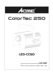
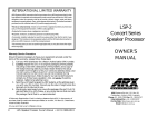
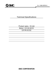
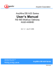
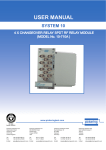
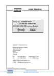
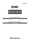
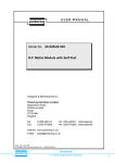
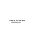
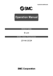
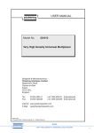
USER MANUAL
pickering
Model No. 20-210
20-410
Breadboard & Digital Input/Output
Modules
Note: 20-210 has been upgraded to 20-210A with ZIF front
panel connectors replacing Elco types.
All other functionality is the same.
Please contact Pickering for new pin-out information
Designed & Manufactured by:Pickering Interfaces Limited.
Stephenson Road
Clacton-on-Sea
Essex
CO15 4NL
England
Tel:
Fax:
+44 1255-428141
+44 1255-475058
01255-428141 (UK)
01255-475058 (UK)
Internet: www.pickeringswitch.com
E Mail: [email protected]
Issue 1.00 Mar 1999
© Copyright (1999) Pickering Interfaces Ltd. All Rights Reserved
pickering
20-210/410
BREADBOARD & DIGITAL INPUT/OUTPUT MODULES
1
HELP!!!
If you need assistance with your Pickering Interfaces Switching
System: Switching problems, Programming or Integration within your Test
System. – Please ring Pickering Interfaces and ask for “Technical
Support”.
Alternatively you may fax, email or connect to our Internet Web Site.
A full set of operating manuals, application notes and software drivers is
available on CD ROM.
pickering
2
20-210/410
BREADBOARD & DIGITAL INPUT/OUTPUT MODULES
Contents
Section 1
Breadboard & Digital Input/Output Modules .............................................................. 5
Section 2
Programming ............................................................................................................. 9
Section 3
Self Test .................................................................................................................... 11
Section 4
Front Panels and Connector Pin-Out Diagrams ...................................................... 13
Section 5
PCB Layouts ............................................................................................................ 19
Section 6
Electrical, Environmental, Mechanical & Firmware Specifications ......................... 25
pickering
20-210/410
BREADBOARD & DIGITAL INPUT/OUTPUT MODULES
3
20-410 Digital I/O Module
pickering
4
20-210/410
BREADBOARD & DIGITAL INPUT/OUTPUT MODULES
Section 1
Breadboard & Digital Input/Output Modules
1.1 Features
• Breadboard and Digital I/O Modules Share The Same Architecture
• Choice of 32 or 64 Bits of Digital Input/Output, Programmable by Bit, Byte or Word.
• T.T.L. Output Suitable for Driving External Logic.
• Transistor Outputs Suitable for Driving External Relay Coils.
• Breadboard Has Large Area For Construction Of User Circuits
• Digital I/O Circuitry Mounted on Daughter Boards For Easy Upgrading and Maintenance
1.2 Breadboard Module Overview
The 20-210 Breadboard module has a choice of 64 or 128 digital pins.
20-210 Breadboard Modules:
20-210-021
20-210-022
20-210-023
20-210-041
20-210-042
20-210-043
Options: -O
Breadboard Module with 2 x 16 Bit Input/Output
2 x 75 Way Elco
Breadboard Module with 2 x 32 Bit Output
2 x 75 Way Elco
Breadboard Module with 2 x 32 Bit Input
2 x 75 Way Elco
Breadboard Module with 4 x 16 Bit Input/Output
2 x 75 Way Elco
Breadboard Module with 4 x 32 Bit Output
2 x 75 Way Elco
Breadboard Module with 4 x 32 Bit Input
2 x 75 Way Elco
Open collector transistor output. Alternative Connectors are available to order.
20-120 modules have
been upgraded to
20-120A.
75-way Elco connectors
have been replaced by
96-way ZIF connectors.
Please consult factory
for details.
1.3 Digital I/O Module Overview
The 20-410 Digital I/O module has a choice of 64 or 128 digital pins. Operation is the same as the 20-210 Breadboard
Module.
20-410 Digital I/O Modules
20-410-021
20-410-022
20-410-023
20-410-041
20-410-042
20-410-043
Options: -O
High Density Digital Module with 32 Bit Input/Output
High Density Digital Module with 64 Bit Output
High Density Digital Module with 64 Bit Input
High Density Digital Module with 64 Bit Input/Output
High Density Digital Module with 128 Bit Output
High Density Digital Module with 128 Bit Input
Open collector transistor output.
pickering
2 x DIN 41612
2 x DIN 41612
2 x DIN 41612
2 x DIN 41612
2 x DIN 41612
2 x DIN 41612
20-210/410
BREADBOARD & DIGITAL INPUT/OUTPUT MODULES
5
1.4 T.T.L. Output Driver
Driver I.C. fitted as standard
Xilinx 3030 gate array.
Maximum drive capability
15 TTL inputs.
Current drive
Sink: 10mA max, Source 0.4mA max.
Max Voltage
Operate/Release Time
7V
< 3mS after internal bus DAV true.
1.5 Open Collector Transistor
CO M
(V
r)
O utput
Driver I.C. fitted as standard
ULS2803, sink driver
Maximum Standoff Voltage
Max Power per O/P
Max Power per byte
Max Current Drive
Operate/Release Time
50V
1.0W
1.6W
500mA.
< 3mS after internal bus DAV true.
Ground
Fig 1.2 Open Collector Output
1.6 Digital Input (all models)
Driver I.C. fitted as standard
Xilinx 3030 gate array.
Maximum Standoff Voltage
7V
Input Current
Iih = 20µA, Iil = -0.4mA
Pull up resistor
Pull up to 5V via 10kOhm resistor
Nominal True voltage
> 2.0V
Nominal false voltage
< 0.8V
Data is strobed in when READ? operation is executed.
1.7 Width and Dimensions
All models conform to the 6U height (233mm) Eurocard standard and are housed in a 160mm deep screened plug-in
card . Panel width is:
20-210 2.4 Inches for standard versions.
20-410 2.4 Inches
1.8 Precautions
Note: Care must be taken when interfacing the 20-210/410 module with external circuits which may produce high voltage
spikes or RF interference. Addition noise protection may be required, please contact Pickering if you wish to discuss your
requirement.
OUT1
OUT1
IN1
OUT2
OUT2
IN2
OUT128
IN128
OUT64
IN1
IN2
IN64
Fig 1.1 128 Bit of Digital I/O
pickering
6
20-210/410
BREADBOARD & DIGITAL INPUT/OUTPUT MODULES
20-210 Breadboard Module
Note: The 20-210 has been upgraded to 20-210A.
75-way Elco connectors have been replaced by 96-pin ZIF types,
please contact Pickering for new pin-out information
pickering
20-210/410
BREADBOARD & DIGITAL INPUT/OUTPUT MODULES
7
pickering
8
20-210/410
BREADBOARD & DIGITAL INPUT/OUTPUT MODULES
Section 2
Programming
2.1 Select Module Address
The module internal address is factory pre-set, please refer to case schematic diagram at front of manual. To change the
internal address please refer to separate manual for Reconfiguring Driver Card to Your Application.
2.2 Programming Using the Intelligent GPIB/RS-232 Interface
The 20-210/410 module is simple to program either by single bit or by word.
ARESET a
Clear all outputs on module a
CLOSE a,b
Set bit number b on module a
DELAY t
Force a minimum delay of t milliseconds between two instructions
OPEN a,b
Clear bit number b on module a
RESET
Clear all bits/switches on all modules
READ? a,c
Read word from module a block position c (word size is a set with the SIZE command)
READ? a,c,b Read bit b from module a block position c
This is used to specify the word size: s = 1 for byte, s = 2 for 16 bit word and s = 3 for 32 bit word (16 bit
is usually the factory default).
VIEW? a[,b] View status of module a, can be viewed at any time either as a word or by bit b as a logical value (1 or 0)
WRITE a,c,w Send word w to module a block position c (word size is a set with the SIZE command)
SIZE s
The module is programmed as an 8 bit output port using either single bit, byte (8 bits), 16 bit word or 32 bit word:To set bit number 55 on module 11.
CLOSE 11,55
Or to close first 16 bits on module 9.
SIZE 2 (this selects byte length words)
WRITE 8,1,65535
For more details on programming see the programming manual for the IEEE-488.2/RS-232 interface module.
2.3 Operating Speed
Module operating speed, i.e. the time taken to open or close a bit, is approximately 7mS using the 10-921 IEEE-488.2/
RS-232 interface module.
pickering
20-210/410
BREADBOARD & DIGITAL INPUT/OUTPUT MODULES
9
pickering
10
20-210/410
BREADBOARD & DIGITAL INPUT/OUTPUT MODULES
n
b
examples:
ARESET 8 (clear module 8)
ARESET 8,3 (clear module 8
bank 3)
(send word to
module 5)
c,
READ? a
READ? a,n
w
CHAN a,c
CHAN a,b,c
CHAN a,b,c,e
e
b,
a,
CHAN
Multiplexer
n
a,
READ?
Digital Input
b,
a,
WRITE
WRITE a,w
WRITE a,b,w
example:
WRITE 5,65264
n
a,
OPEN
CLOSE a,n
example:
CLOSE 5,9 (close relay 9
on module 5)
a,
a,
ARESET a
ARESET a,b
CLOSE
Switch/Digital Output
ARESET
Clear
y
x,
b,
a,
MOPEN a,x,y
MOPEN a,b,x,y
y
x,
b,
a,
MCLOSE MOPEN
Matrix
t
DELAY
Time
n
b,
b
TYPE?
Status
a
DIAGNOSTIC?
Errors
November 1995
Section 3
Self Test
3.1 Self-Test Function
Self-Test is invoked at power on and may also be operated under software (*TST?). Self-Test pass is indicated on a front
panel LED with a full pass/fail description available using the DIAGNOSTIC? command.
Self-Test comprises 1 levels, see diagram below:1.
Logic Test: Checks all logic including on-board microprocessor, relay drivers etc.
3.2 Self-Test Operation
If self test is run under software control it will firstly clear the whole module.
When the selftest has finished the module will be returned to an all clear state (i.e. the previous state will not be
remembered!).
3.3 Detailed Self Test Reporting using the DIAGNOSTIC? Query
The DIAGNOSTIC? query will give an ASCII string detailing any self test failures. These will include:Logic: µP, RAM, EPROM, Relay Drivers, Invalid Link Settings etc.
This string is not intended to be processed by the user’s software, it is suitable for copying directly onto the screen of your
control computer. This information will then indicate the maintenance required (please contact Pickering for further help).
SELF TEST INITIATED BY:
• POWER ON
• *TST? QUERY
• MANUAL BUTTON
CLEAR MODULE
LOGIC TEST:
• µP BOARD
• RELAY BOARD
LOGIC
TEST FAIL
Self-Test: Basic Flow
Diagram
YES
NO
RELAY COIL TEST
COIL
TEST FAIL
YES
NO
SELF TEST PASS
pickering
SELF TEST FAIL:
• ERROR LED ON
• USE DIAGNOSTIC?
COMMAND TO GET
ERROR MESSAGE
20-210/410
BREADBOARD & DIGITAL INPUT/OUTPUT MODULES
11
pickering
12
20-210/410
BREADBOARD & DIGITAL INPUT/OUTPUT MODULES
Section 4
Front Panels and Connector Pin-Out Diagrams
LED (red) Module
powered on
POW
LED (green) Indicates if
any switch is operated
ACT
TEST
ERR
LED (yellow) Self-Test
Currently Running
Fig 4.1 20-210 Front Panel
Many Breadboard Modules Are Shipped
With Special Front Panels Which May
Look Different to This
LED (red) error found
4
5
2
3
2
6
1
3
during self-test
4
5
6
7
A
B
C
D
E
F
J
K
L
M
N
6
3
4
pickering
2
Note: The 20-210 has been upgraded to 20-210A.
75-way Elco connectors have been replaced by
96-pin ZIF types, please contact Pickering for new
pin-out information
5
P
Fig 4.2 Elco Connector Pin Out
20-210/410
BREADBOARD & DIGITAL INPUT/OUTPUT MODULES
13
A1
A2
A3
A4
A5
A6
A7
__________
__________
__________
__________
__________
__________
__________
B1
B2
B3
B4
B5
B6
B7
__________
__________
__________
__________
__________
__________
__________
C1
C2
C3
C4
C5
C6
C7
__________
__________
__________
__________
__________
__________
__________
D2
D3
D4
D5
D6
D7
__________
__________
__________
__________
__________
__________
E1 __________
E2 __________
E3 __________
E5 __________
E6 __________
E7 __________
F1
F2
F6
F7
__________
__________
__________
__________
H1 __________
J1
J2
J6
J7
__________
__________
__________
__________
K1
K2
K3
K5
K6
K7
__________
__________
__________
__________
__________
__________
L2
L3
L4
L5
L6
L7
__________
__________
__________
__________
__________
__________
M7 __________
N1
N2
N3
N4
N5
N6
N7
__________
__________
__________
__________
__________
__________
__________
P1
P2
P3
P4
P5
P6
P7
__________
__________
__________
__________
__________
__________
__________
SHIELD
M1 __________
M2 __________
M3 __________
M4 __________
M5 __________
M6 __________
Table 4.1 Documentation Table for 75 Way Connector (Suitable for Photocopying)
Note: The 20-210 has been upgraded to 20-210A.
75-way Elco connectors have been replaced by 96-pin ZIF types,
please contact Pickering for new pin-out information
14
pickering
20-210/410
BREADBOARD & DIGITAL INPUT/OUTPUT MODULES
LED (red) Module
powered on
A
a
c 32
POW
LED (green) Indicates if
any switch is operated
ACT
TEST
LED (yellow) Self-Test
Currently Running
ERR
LED (red) error found
during self-test
a
c
1
B
a
c 32
a
c
1
Fig 4.3 20-410 Front Panel
pickering
20-210/410
BREADBOARD & DIGITAL INPUT/OUTPUT MODULES
15
32
31
30
29
28
27
26
25
24
23
22
21
20
19
18
17
16
15
14
13
12
11
10
9
8
7
6
5
4
3
2
1
A
Out 1
Out 4
Out 7
Out 10
Out 13
Out 16
Out 19
Out 22
Out 25
Out 28
Out 31
COM1
GND
GND
GND
Out 35
Out 38
Out 41
Out 44
Out 47
Out 50
Out 53
Out 56
Out 59
Out 62
B
Out 2
Out 5
Out 8
Out 11
Out 14
Out 17
Out 20
Out 23
Out 26
Out 29
Out 32
COM1
GND
GND
COM2
Out 33
Out 36
Out 39
Out 42
Out 45
Out 48
Out 51
Out 54
Out 57
Out 60
Out 63
C
Out 3
Out 6
Out 9
Out 12
Out 15
Out 18
Out 21
Out 24
Out 27
Out 30
GND
GND
GND
COM2
Out 34
Out 37
Out 40
Out 43
Out 46
Out 49
Out 52
Out 55
Out 58
Out 61
Out 64
32
31
30
29
28
27
26
25
24
23
22
21
20
19
18
17
16
15
14
13
12
11
10
9
8
7
6
5
4
3
2
1
A
Out 65
Out 68
Out 71
Out 74
Out 77
Out 80
Out 83
Out 86
Out 89
Out 92
Out 95
COM3
GND
GND
GND
Out 99
Out 102
Out 105
Out 108
Out 111
Out 114
Out 117
Out 120
Out 123
Out 126
Connector A
B
Out 66
Out 69
Out 72
Out 75
Out 78
Out 81
Out 84
Out 87
Out 90
Out 93
Out 96
COM3
GND
GND
COM4
Out 97
Out 100
Out 103
Out 106
Out 109
Out 112
Out 115
Out 118
Out 121
Out 124
Out 127
C
Out 67
Out 70
Out 73
Out 76
Out 79
Out 82
Out 85
Out 88
Out 91
Out 94
GND
GND
GND
COM4
Out 98
Out 101
Out 104
Out 107
Out 110
Out 113
Out 116
Out 119
Out 122
Out 125
Out 128
Connector B
Table 4.2 Pin Out Table For 20-410 - 128 Bit Output Configuration
32
31
30
29
28
27
26
25
24
23
22
21
20
19
18
17
16
15
14
13
12
11
10
9
8
7
6
5
4
3
2
1
A
In 1
In 4
In 7
In 10
In 13
In 16
In 19
In 22
In 25
In 28
In 31
COM1
GND
GND
GND
In 35
In 38
In 41
In 44
In 47
In 50
In 53
In 56
In 59
In 62
B
In 2
In 5
In 8
In 11
In 14
In 17
In 20
In 23
In 26
In 29
In 32
COM1
GND
GND
COM2
In 33
In 36
In 39
In 42
In 45
In 48
In 51
In 54
In 57
In 60
In 63
C
In 3
In 6
In 9
In 12
In 15
In 18
In 21
In 24
In 27
In 30
GND
GND
GND
COM2
In 34
In 37
In 40
In 43
In 46
In 49
In 52
In 55
In 58
In 61
In 64
32
31
30
29
28
27
26
25
24
23
22
21
20
19
18
17
16
15
14
13
12
11
10
9
8
7
6
5
4
3
2
1
A
In 65
In 68
In 71
In 74
In 77
In 80
In 83
In 86
In 89
In 92
In 95
COM3
GND
GND
GND
In 99
In 102
In 105
In 108
In 111
In 114
In 117
In 120
In 123
In 126
Connector A
B
In 66
In 69
In 72
In 75
In 78
In 81
In 84
In 87
In 90
In 93
In 96
COM3
GND
GND
COM4
In 97
In 100
In 103
In 106
In 109
In 112
In 115
In 118
In 121
In 124
In 127
C
67
70
73
76
79
82
85
88
91
94
GND
GND
GND
COM4
In 98
In 101
In 104
In 107
In 110
In 113
In 116
In 119
In 122
In 125
In 128
In
In
In
In
In
In
In
In
In
In
Connector B
Table 4.3 Pin Out Table For 20-410 - 128 Bit Input Configuration
pickering
16
20-210/410
BREADBOARD & DIGITAL INPUT/OUTPUT MODULES
32
31
30
29
28
27
26
25
24
23
22
21
20
19
18
17
16
15
14
13
12
11
10
9
8
7
6
5
4
3
2
1
A
Out 1
Out 4
Out 7
Out 10
Out 13
Out 16
In 19
In 22
In 25
In 28
In 31
COM1
GND
GND
GND
Out 35
Out 38
Out 41
Out 44
Out 47
In 50
In 53
In 56
In 59
In 62
B
Out 2
Out 5
Out 8
Out 11
Out 14
In 17
In 20
In 23
In 26
In 29
In 32
COM1
GND
GND
COM2
Out 33
Out 36
Out 39
Out 42
Out 45
Out 48
In 51
In 54
In 57
In 60
In 63
C
Out 3
Out 6
Out 9
Out 12
Out 15
In 18
In 21
In 24
In 27
In 30
GND
GND
GND
COM2
Out 34
Out 37
Out 40
Out 43
Out 46
In 49
In 52
In 55
In 58
In 61
In 64
32
31
30
29
28
27
26
25
24
23
22
21
20
19
18
17
16
15
14
13
12
11
10
9
8
7
6
5
4
3
2
1
A
Out 65
Out 68
Out 71
Out 74
Out 77
Out 80
In 83
In 86
In 89
In 92
In 95
COM3
GND
GND
GND
Out 99
Out 102
Out 105
Out 108
Out 111
In 114
In 117
In 120
In 123
In 126
Connector A
B
Out 66
Out 69
Out 72
Out 75
Out 78
In 81
In 84
In 87
In 90
In 93
In 96
COM3
GND
GND
COM4
Out 97
Out 100
Out 103
Out 106
Out 109
Out 112
In 115
In 118
In 121
In 124
In 127
C
Out 67
Out 70
Out 73
Out 76
Out 79
In 82
In 85
In 88
In 91
In 94
GND
GND
GND
COM4
Out 98
Out 101
Out 104
Out 107
Out 110
In 113
In 116
In 119
In 122
In 125
In 128
Connector B
Table 4.4 Pin Out Table For 20-410 - 64 Bit Input/Output Configuration
pickering
20-210/410
BREADBOARD & DIGITAL INPUT/OUTPUT MODULES
17
PIN
FUNCTION
1
2
3
4
5
6
7
8
9
10
11
12
13
14
15
16
17
18
19
20
21
22
23
24
25
26
27
28
29
30
31
32
33
34
35
36
37
38
39
40
41
42
43
44
45
46
47
48
49
50
51
52
53
54
55
56
57
58
59
60
61
62
63
64
65
66
67
68
69
70
71
72
COM
COM
GND
GND
I/O BIT 1
I/O BIT 2
I/O BIT 3
I/O BIT 4
I/O BIT 5
I/O BIT 6
I/O BIT 7
I/O BIT 8
I/O BIT 9
I/O BIT 10
I/O BIT 11
I/O BIT 12
I/O BIT 13
I/O BIT 14
I/O BIT 15
I/O BIT 16
I/O BIT 17
I/O BIT 18
I/O BIT 19
I/O BIT 20
I/O BIT 21
I/O BIT 22
I/O BIT 23
I/O BIT 24
I/O BIT 25
I/O BIT 26
I/O BIT 27
I/O BIT 28
I/O BIT 29
I/O BIT 30
I/O BIT 31
I/O BIT 32
5V
5V
COM
COM
GND
GND
D0
D1
D2
D3
D4
D5
D6
D7
CS6
WR
A0
A1
A2
BA1
BA2
LCLK
LDATA
RDATA1
RESET OUT
SEN1
CS5
CS (5832)
5V
5V
GND
GND
GND
GND
Table 4.5 Pin Out For Digital I/O SIM Card
pickering
18
20-210/410
BREADBOARD & DIGITAL INPUT/OUTPUT MODULES
Section 5
20-210/410 PCB Layouts
System 20
Screened
24 Pole
Backplane
Digital
I/O
SIM
Slot#1
Digital
I/O
SIM
Slot#2
Digital
I/O
SIM
Slot#3
DIP
Construction
Area With
Bussed 0V
and 5V
Rails
Wiring Point For Bits 97 to 128
Digital I/O SIM Card #4 (Bits 97 to 128)
Wiring Point For Bits 65 to 96
Digital I/O SIM Card #3 (Bits 65 to 96)
Wiring Point For Bits 33 to 64
Digital I/O SIM Card #2 (Bits 33 to 64)
Wiring Point For Bits 1 to 32
Digital I/O SIM Card #1 (Bits 1 to 32)
Controller SIM Card
System 10
Screened
10 Pole
Backplane
DIP
Construction
Area With
Bussed 0V
and 5V
Rails
Square Pad
Breadboard
Area
Square Pad
Breadboard
Area
Digital
I/O
SIM
Slot#4
Fig 5.1. 20-210 Breadboard PCB - Main Functional Blocks Shown
pickering
20-210/410
BREADBOARD & DIGITAL INPUT/OUTPUT MODULES
19
Fig 5.2 Top Side Of Main PCB For 20-210/410 Module (see Fig 5.1 for description)
pickering
20
20-210/410
BREADBOARD & DIGITAL INPUT/OUTPUT MODULES
Fig 5.3 Bottom Side Of Main PCB For 20-210/410 Module
pickering
20-210/410
BREADBOARD & DIGITAL INPUT/OUTPUT MODULES
21
Bit 32
Bit 31
Bit 30
Bit 29
Bit 28
Bit 27
Bit 26
Bit 25
Bit 24
Bit 23
Bit 22
Bit 21
Bit 20
Bit 19
Bit 18
Bit 17
Bit 16
Bit 15
Bit 14
Bit 13
Bit 12
Bit 11
Bit 10
Bit 9
Bit 8
Bit 7
Bit 6
Bit 5
Bit 4
Bit 3
Bit 2
Bit 1
Com
Bit 63
Bit 61
Bit 59
Bit 57
Bit 55
Bit 53
Bit 51
Bit 49
Bit 47
Bit 45
Bit 43
Bit 41
Bit 39
Bit 37
Bit 35
Bit 33
Com
Bit 64
Bit 62
Bit 60
Bit 58
Bit 56
Bit 54
Bit 52
Bit 50
Bit 48
Bit 46
Bit 44
Bit 42
Bit 40
Bit 38
Bit 36
Bit 34
Bit 96
Bit 95
Bit 93
Bit 91
Bit 89
Bit 87
Bit 85
Bit 83
Bit 81
Bit 79
Bit 77
Bit 75
Bit 73
Bit 71
Bit 69
Bit 67
Bit 65
Bit 94
Bit 92
Bit 90
Bit 88
Bit 86
Bit 84
Bit 82
Bit 80
Bit 78
Bit 76
Bit 74
Bit 72
Bit 70
Bit 68
Bit 66
Bit 128
Bit 127
Bit 126
Bit 125
Bit 124
Bit 123
Bit 122
Bit 121
Bit 120
Bit 119
Bit 118
Bit 117
Bit 116
Bit 115
Bit 114
Bit 113
Bit 112
Bit 111
Bit 110
Bit 109
Bit 108
Bit 107
Bit 106
Bit 105
Bit 104
Bit 103
Bit 102
Bit 101
Bit 100
Bit 99
Bit 98
Bit 97
Com
Com
Fig 5.4 Digital I/O Connection Points For 20-210 Module
pickering
22
20-210/410
BREADBOARD & DIGITAL INPUT/OUTPUT MODULES
Fig 5.5 Digital I/O SIM Card Top and Bottom Layout
pickering
20-210/410
BREADBOARD & DIGITAL INPUT/OUTPUT MODULES
23
pickering
24
20-210/410
BREADBOARD & DIGITAL INPUT/OUTPUT MODULES
Section 6
Electrical, Environmental, Mechanical & Firmware Specifications
Environmental
Operating Temperature 0°C to 50°C.
Storage Temperature -20°C to 75°C.
Humidity 95% non condensing.
Weight Dimensions and Power Requirements
Approx. Weight/g
1100
Dimensions/mm †
Front Panel Width
60.
Height
268
Overall Length
189
Power /Current
Consumption
Maximum 5V
/mA
12V
250
0
Minimum
150
0
5V
12V
† Approx. dimensions. Standard 160mm, 6U, Eurocard, as specified in DIN 41494.
Voltage Supplies
Logic Supply 5Vdc ±5%.
pickering
20-210/410
BREADBOARD & DIGITAL INPUT/OUTPUT MODULES
25
pickering
26
20-210/410
BREADBOARD & DIGITAL INPUT/OUTPUT MODULES