Transcript
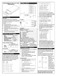
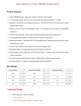
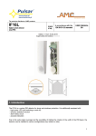
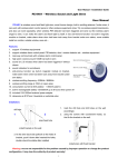
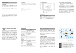
V1.5 2009-11-06 BOM 31011980 IRM-S04DI Intelligent Digital Input Sensor With Phoenix Ports User Manual "0" means no alarm Sensor address "1" means alarm exists 1.1.6 Alarm Indicator 1 Overview IRM-S02TH intelligent digital input sensor with phoenix ports (sensor for short) is used to measure 4 routes digital input (such as infrared, smoke, door status and water). It supports MODBUS protocol through RJ45 port in RS-485 mode to configure and collect data. It is applicable for indoor sites which need digital signal control such as communication rooms and IT data centers. 1.1 Note: "-" means no equipment connected Measured data Product Introduction Technical Specification Operating voltage: 9Vdc ~ 28Vdc; Power consumption: 0.2W 2 Installation Environment Requirement 1. Operating environment should be free of conductive dust and metal-corrosive & insulation-breaking gases. The sensor’s appearance and ports are shown in the following figure. 2. Avoid using the sensor in watery or foggy places. Fixed Group Num OFF: ON: User 12345678 RJ45 port D1 V+ GND D2 V+(12/24V) GND Door1/DI 1 Door2/DI 2 Alarm indicator D3 V+ GND D4 V+(12/24V) GND Water/DI 3 Smoke/DI 4 LCD display panel ALARM Phoenix port 1 Digital Input Sensor IRM-S04DI 1 2 3 4 Phoenix port 2 RJ45 port 1.2 2.1 1.1.1 Appearance and Ports Left view When measured digital level is the same as configured digital level correspondingly, the alarm indicator flashes; or the indicaor extinguishes. Front view 3. Keep a clearance of more than 20mm around the sensor’s airway to ensure ventilation inside and outside of the sensor. 4. Operating temperature: -10°C ~ +50°C; Storage temperature: -30°C ~ +70°C; Humidity: 5% ~ 95%RH (non-condensing). DIP switch 2.2 Phoenix port 4 Phoenix port 3 2.3 Right view Size (height × width × depth): 97mm × 44mm × 22mm Weight: about 100g 1.1.2 RJ45 Port Pin1 and Pin2 Pin3 and Pin6 Pin4 and Pin5 Pin7 Pin8 Definition +12V/24V NC GND D+ D- Mechanical Installation Three modes are available for the sensor’s mechanical installation. The installation accessories and modes are shown in the following figure. Two RJ45 ports are used in the electric connection of the sensor for power supply, communication and equipment connection in series. The definition of RJ45 ports is shown in the following table. Pin Unpacking Inspection Unpack the sensor and visually inspect the sensor’s appearance. If any damage is found, please contact the carrier immediately. Check against the consignment list to make sure the sensor and accessories are complete and correct. Back installation hole Magnet pothook Sensor L pothook 1.1.3 Phoenix Port Pin1 Pin 2 Pin 3 Pin 4 Definition GND Equipment detection Signal +12V/24V 1.1.4 DIP Switch The DIP switch is used to set sensor address and connected equipment type to communicate with upper equipment through MODBUS protocol. The sensor address is composed of group number and serial number within the group. The DIP1 ~ DIP4 are used to set the group number; The DIP5 are used to set the serial number within the group; The DIP6 is used to set the type of connected equipment. For example, the sensor address of 70 is set as shown in the following figure, among which 0111 means group number 7; 0 means serial number 0 within the group and 1 means that the type of connected equipment is user customized equipment. 0 1 1 1 0 1 1 2 3 4 5 6 DIP ON Group Num Note: 1. DIP switch in the ON position means 1, or it means 0; 2. The sensor address cannot be set as 00, which is the broadcast address. OFF: Fixed T pothook Mode one: Insert the magnet pothook into the sensor’s back installation hole, and the sensor can absorb on iron surface. Mode two: Insert the L pothook into the sensor’s back installation hole, and hang the pothook in the square hole of rack’s column with care. Mode three: Insert the T pothook into the sensor’s back installation hole, insert the bulge of the T pothook into the installation slot of the rack’s basic frame, and rotate the sensor 90 degree clockwise with care. Note The sensor can not only be installed through the three kinds of accessories above, but also can hang on fixed screws directly through the installation hole. 2.4 Cable Connection 1. Insert one end of the standard straight network cable into the sensor’s RJ45 port, and insert the other end into the sensor appropriative port of upper equipment or sensor in series. 2. Refer to 1.1.3 Phoenix Port for port definition, and connect cables as shown in the following figure. GND Door Equipment detect status, DI signal input water, DI signal input smoke ON: User The settings of DIP1 ~ DIP4 are listed in the following table. DIP1 ~ DIP4 0000 0001 0010 0011 Group 0 1 2 3 DIP1 ~ DIP4 0100 0101 0110 0111 Group 4 5 6 7 DIP1 ~ DIP4 1000 1001 1010 1011 Group 8 9 A b DIP1 ~ DIP4 1100 1101 1110 1111 Group C d E F The settings of DIP5, DIP6 are listed in the following table. DIP5 0 1 Num 0 1 DIP6 0 1 Connected equipment type Fixed equipment User customized equipment 1.1.5 LCD Display Panel The LCD display panel (as shown in the following figure) can display sensor address and measured data in real time. The four numbers from left to right in the data area means the status of input digital 1, 2, 3 and 4 respectively. GND Equipment detect Infrared DI signal input DI signal input +12V/24V Phoenix port Pin Back installation hole Phoenix port Four phoenix ports are used to connect 4 routes digital equipment. The sensor can measure and display whether any equipment is connected and its status. The phoenix ports also supply +12V/24V power supply, which is the same as the input power supply of the sensor, to the connected equipment. The pin definition of the phoenix ports is shown in the following table. 3 Maintenance 1. To clean the sensor, you should cut off the power and use a piece of soft cloth to wipe it. 2. Do not disassemble the sensor, or the inside subtle parts may be damaged.