Transcript
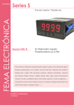
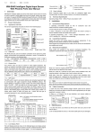
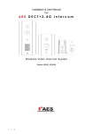
PROGRAMMABLE RELAY I/O CARD
USER MANUAL
R4
+---------------------------+
|
Customize Output Relay |
+---------------------------+
Relay
Selected Event
[1].Relay1: Summary Alarm
[2].Relay2: Power Fail
[3].Relay3: Battery Low
[4].Relay4: On Bypass
[5].Relay5: Overload
[6] Relay6: Over Temperature
[0].Back To Previous Menu
R5
Please Enter Your Choice =>
INTERNAL CIRCUIT
Common
R1
R2
R3
+5V
Once the configuration is complete SW2
MUST be switched to the ON position to apply
the new settings, switch SW2 back to the OFF
position to reset to the default settings.
3. Press ‘2’ to configure the Input signal.
R6
CPU Pin
GND-R
Input
PRESENTATION
FEATURES
This relay I/O card is an UPS management
product with 6 relay output contacts for monitoring
the status and 1 input contact as a shutdown UPS
or a battery test command.
Features:
z Monitor UPS events.
z 6 programmable relay output contacts.
z Configurable normal open or normal close for
each relay contact.
z Configurable UPS shutdown delay time.
z Configurable input signal as shutdown UPS or
battery test.
z Has the ability to protect up to 6 computers
unattended shutdown gracefully.
TECHNICAL SPECIFICATION
TECHNICAL SPECIFICATION
Size
130 x 60 mm
Weight
200 g
Operating Temperature 0 ~ 40° C
Operating Humidity
10 ~ 80 %
Power Input
8 ~ 20V DC
Power Consumption
1.2 Watts
OUTPUT CONTACT RATING
Maximum
DC Voltage DC Current
Relay
24 V
1A
R1~R6
INPUT RATING
Maximum
DC Voltage DC Current
24 V
10 mA
Input
APPLICATION EXAMPLE
In this case we’ll use the default settings, please
set SW1 and SW2 to the OFF position. Apply
12VDC to Common contact and connect the
lamps to R1~R6 terminals. Install a push button
from the Common contact to the input terminal.
Press the button for at least 3 seconds to
shutdown the UPS remotely.
Common
+12V
GND-R
R1
Summary Alarm
R2
Power Fail
R3
Battery Low
R4
On Bypass
R5
Overload
R6
Over Temperature
Input
Shutdown UPS
OUTLINE
GND-R
Common
R1
R2
R3
R4
R5
R6
Input
Tx
Rx
GND-C
SW1
SW2
I/O PINOUT
GND-R: Ground for relays
Common: 12~24VDC
Default Alarm Event
R1
Summary Alarm
R2
Power Fail
R3
Battery Low
R4
On Bypass
R5
Overload
R6
Over Temperature
Input: Remote shutdown or battery test
Tx: Transmit to PC, connect to sub9-pin2
Rx: Receive from PC, connect to sub9-pin3
GND-C: Ground for configuration Tx and Rx pins
OFF (Default)
ON
SW1 Normal open
Normal close
for default settings for default settings
SW2 Default settings
Customized settings
PROGRAMMABLE CONTACTS
COMMUNICATION SETUP
1. Connect Tx to pin2, Rx to pin3 and GND-C to
pin5 of PC RS232 port.
2. In the Windows environment, launch the
Hyper- Terminal program then open the
specified COM port.
3. Set the following properties:
Baud rate: 2400, Data Bits: 8, Parity: None
Stop Bit: 1, Flow Control: None
CONFIGURATION
1. Press <Enter> to get the main menu of the
programmable relay card.
+---------------------------+
|
UPS Relay Card
|
+---------------------------+
Firmware Version: Relay Card V1.4
[1].Customize Output Relay
[2].Configure Input Signal
[3] Customize Normal Open or Normal Close
[0].Quit
Please Enter Your Choice =>
2. Press ‘1’ to configure the alarm event for
R1~R6.
Contacts R1~R6 can be configured for
different power events.
+---------------------------+
| Configure Input Signal |
+---------------------------+
[1].Act as Shutdown or Test: Shutdown
[2].Input Signal Confirm: 3 Seconds
[3].Delay Before Shutdown: 30 Seconds
[0].Back To Previous Menu
Please Enter Your Choice =>
In this menu, the input signal can be redefined
as shutdown UPS or battery test signal.
Meanwhile, the UPS shutdown delay time is
also adjustable to a maximum of 9999
seconds.
4. Press ‘3’ to configure the normal open or
normal close for each relay.
+---------------------------+
| Customize Output Relay |
+---------------------------+
Relay Selected Event
[1].Relay1: Normal Close
[2].Relay2: Normal Open
[3].Relay3: Normal Close
[4].Relay4: Normal Open
[5].Relay5: Normal Close
[6].Relay6: Normal Open
[0].Back To Previous Menu
Please Enter Your Choice =>
Once the configuration is complete SW2
MUST be switched to the ON position to apply
the new settings. Switch SW2 back to the
OFF position to reset to the default settings.
5. Press ‘0’ to quit this configuration session.
The system would prompt you to save or not.
Press ‘Y’ to save your settings, ‘N’ to ignore.
POWER OPTION IN WIN 2000/XP
This relay card has the ability to provide UPS
signals for Windows NT4/2000/XP/2003. First
connect the RS232 port on the PC to the relay
card as shown:
Then open the power option from control panel
and click on the UPS tab to setup the signals
polarity, select Positive for Power Fail, Low
Battery and UPS
Common
Shutdown.
RTS pin7
GND-R
Since the R1~R6
GND pin5
contacts are
R1
programmable,
R2
Power Fail
the output
CTS pin8
R3
Battery Low
contacts can be
DCD pin1
configured for 3
R4
computers with 2
R5
signals (power fail
and low battery) or
R6
6 computers with
Shutdown UPS Input
DTR pin4
one signal (power
fail or low battery).
Note: All of the computers must have the same
earth ground potential. Connect all of the
computers input power to the same UPS.