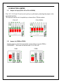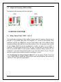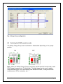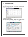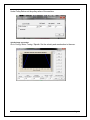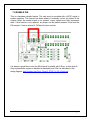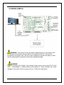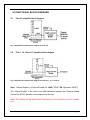
1
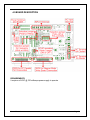
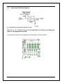
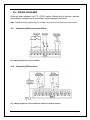
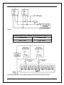
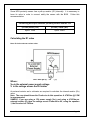
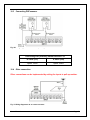
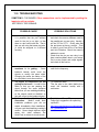
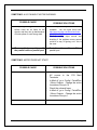
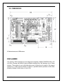
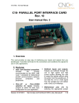
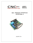
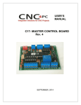
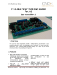
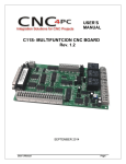
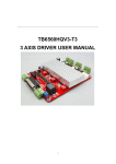
USER’S MANUAL C33 - MULTIFUNCTION ROUTER BOARD BOARD Rev 2.4 FEBRUARY, 2015 User’s Manual Page i USER'S MANUAL TABLE OF CONTENTS Page # Contents 1.0 OVERVIEW .......................................................................................................... 1 2.0 FEATURES .......................................................................................................... 1 3.0 SPECIFICATIONS ............................................................................................... 2 4.0 BOARD DESCRIPTION ....................................................................................... 3 5.0 SELECTION JUMPER ......................................................................................... 4 5.1 Jumper for Input (PULL-UP or PULL-DOWN) ................................................. 4 5.2 Jumper for (PWM or FREQ) ............................................................................. 4 5.3 Jumper for Frequency (50Hz or 60Hz) ............................................................ 5 6.0 SPECIAL FUNCTIONS ........................................................................................ 5 6.1 Safety Charge Pump “SCHP”. (Pin 17) .......................................................... 5 6.2 Selecting the SCHP operation mode ............................................................... 6 6.3 Configuring the Control Software: .................................................................. 7 7.0 ENABLE PIN ........................................................................................................ 9 8.0 WIRING SAMPLE .............................................................................................. 10 9.0 FUNCTIONAL BLOCK DIAGRAMS .................................................................. 11 9.1 Pins 2-9 simplified block diagram ............................................................... 11 9.2 Pins 1, 14, 16 and 17 simplified block diagram .......................................... 11 9.3 Inputs simplified block diagram .................................................................. 12 10.0 WIRING DIAGRAMS .......................................................................................... 13 10.1 Connecting Switches or push button.......................................................... 13 10.2 Connecting NPN sensors. ............................................................................ 13 10.3 Connecting PNP sensors. ............................................................................ 16 10.4 Other connection. ......................................................................................... 16 11.0 TROUBLESHOOTING ....................................................................................... 17 12.0 DIMENSIONS ..................................................................................................... 20 User’s Manual Page ii 1.0 OVERVIEW This card provides an easy way of interfacing your router based spindle with your steeper motor driver board. This board includes a speed controller for routers. Additionally provides terminals for inputs to be used as are required by the user. 2.0 FEATURES IEEE 1284 Standard compatible. Includes the circuitry recommended by the IEEE 1284 Level 1 standards for bidirectional parallel communications between personal computers and peripherals. DB25 connector to connect the stepper motor driver board. These connectors manage only pins 2 – 9. Microcontroller based SCHP. This board comes with a microcontroller that allows the implementation of a complex algorithm for sampling and analyzing the SCHP signal. Terminals to control the router speed. Additional Terminals for controlling a coolant pump or vacuum. Speed Control Signal Can Be PWM or 0-25HZ Pulse Stream. Works with 110 or 220VAC at 60 or 50 HZ. For 2.5HP or 1800 Watt Routers. LEDs Show The Operation Mode. Buffered inputs and outputs. Outputs are buffered through the use of high speed and high current buffers allowing the card to output the signals without using the power from the parallel port. It can take the +3.3 or +5vdc signal from the parallel port and deliver solid +5vdc at 24 milliamps. Input and output pins with close by ground or +5vdc connections External Enable Pin (EN). The board has a pin that allows you to enable/disable all the outputs at once. The board requires +5vdc in the EN pin. If it is not present, it will send all the outputs to ground. You can use this to enable or User’s Manual Page 1 disable the system manually, or you can install an external Safety Charge Pump or other external safety monitoring device. Works directly with popular CNC hardware and software. Such as Geckodrive G540, xylotex, HobbyCNC, Rockcliff, or Rutex, and parallel port control software, such as mach2, Linux EMC, TurboCNC, CNCPlayer, CNCZeus and others. (Not all tested). All TTL 5VDC signals. Interface directly with parallel port interface products and other CNC4PC cards. 5VDC (TTL) cards are very common among automation devices. Screw-On connections for all terminals. You only have to screw-on the wires to make all your connections. 3.0 SPECIFICATIONS DIGITAL INPUT SPECIFICATIONS On-state voltage range 2 to 5V DC Maximum off-state voltage 0.8V Maximum operation frequency 4 MHz Typical signal delay 10nS DIGITAL OUTPUT SPECIFICATIONS Maximum output voltage (5V power supply voltage) + 0.5V Typical output current 24mA Maximum off-state voltage 0.44 V Maximum operation frequency 4 MHz Typical signal delay 10 nS Time of transition to high impedance state 120 mS* *Time passed since a low in the ENABLE input is detected and the outputs are disabled. User’s Manual Page 2 4.0 BOARD DESCRIPTION REQUIREMENTS It requires a 5VDC @ 700 milliamps power supply to operate. User’s Manual Page 3 5.0 SELECTION JUMPER 5.1 Jumper for Input (PULL-UP or PULL-DOWN) Pins 10,11,12,13 and 15 can be set to pull-up or pull-down by selecting the jumper in the appropriate position. The input pins can be set to be pulled up or down with a 4.7Kohm resistor. PULL-UP 5.2 PULL-DOWN Jumper for (PWM or FREQ) Set the jumper to select the appropriate control method, it can be PWM or FREQUENCY. The board can be used with 110 or 220 VAC PWM User’s Manual FREQ Page 4 5.3 Jumper for Frequency (50Hz or 60Hz) Set jumper to the frequency with that it will work 50Hz 60Hz 6.0 SPECIAL FUNCTIONS 6.1 Safety Charge Pump “SCHP”. (Pin 17) This board takes advantage of Mach ability to send a specific frequency through one of the pins of the parallel port when the program is in control of the system. CNC machinery can be very dangerous, and you could have a risk of the machine doing something different that what you intend the machine to do if the program loses control of your system. Mach be can be programmed in a way, so when it is “in control”, it delivers a 12.5 KHz signal through one of the pins. This card lets you use this signal to work as an On/Off switch for your system, enabling a powerful safety system for your equipment. If you ever had windows crash on you, then this card is for you. The port can also do weird things while the system is coming up, or down. For Configuring the Charge Pump in Mach X: Use the dialog Config / Ports and pins / Output Signals. Enable the Charge Pump output and configures it as is shown in the Fig. 8 Next, press the apply button. User’s Manual Page 5 Fig. 4 Charge Pump configuration 6.2 Selecting the SCHP operation mode The Safety Charge Pump can be activated or deactivated depending on the jumper position ON OFF Note: When the Safety Charge Pump is activated, the EN terminal is active and a valid SCHP signal is present, pin 17 will go high. This high signal can be used to enable other external devices, such as enabling other Breakout Boards, or relays that would enable servos, VFDs, contactors, etc…. User’s Manual Page 6 6.3 Configuring the Control Software: For configuring Mach X follow these steps: Go to Config / Ports&Pins / Motor Outputs. Enable the spindle and select the port and pins you wired for step and direction. Ports&Pins configuration screenshot Go to Config / Ports&Pins / Spindle Setup. In the motor control box, check Use Spindle Motor Output and PWM Control with a frequency of 300Hz. If using an external motion controller, like the Smooth Stepper, this needs to be configured in the plugin too. User’s Manual Page 7 Under Pulley Ratios set the pulley ratios of the machine. Spindle Setup screenshot Go to Config / Motor Tuning / Spindle. Set the velocity and acceleration to the max. User’s Manual Page 8 7.0 ENABLE PIN This is a hardware disable feature. The card must be provided with a 5VDC signal to enable operation. This feature has been added to externally control the status of the outputs. When the enable signal is not present, output signals sent high impedance state. If this function is not required, an jumper can be placed between +5vdc and the EN terminal. It has an internal 4.7kOhm pull-down resistor. It is always a good idea to wire the EN terminal in parallel with E-Stop, so that when EStop is pressed the system is disabled at hardware level, like it is described in this wiring diagram: http://cnc4pc.com/Tech_Docs/E_STOP_N_EN_Wiring.pdf User’s Manual Page 9 8.0 WIRING SAMPLE WARNING: This card must have the power supplied while it is connected to the PC. If power is removed to the card while it is connected to the PC, noise can be introduced to the output lines. This can create a dangerous situation as relays or other devices that might be connected to this card could get activated. WARNING Check the polarity and voltage of the external power source and connect the 5V and GND. Overvoltage or reverse-polarity power applied to these terminals can cause damage to the board, and/or the power source. Follow the steps bellow. User’s Manual Page 10 9.0 FUNCTIONAL BLOCK DIAGRAMS 9.1 Pins 2-9 simplified block diagram Fig. 1 Simplified functional block diagram for pins 2-9. 9.2 Pins 1, 14, 16 and 17 simplified block diagram Fig. 2 Simplified functional block diagram for outputs 1, 14, 17 and 16. Note: “Internal Enable” = “External Enable Pin” AND (“SCHP” OR “Bypassed SCHP”) The “Internal Enable” is the result of an AND Operation between the “External Enable Pin”and the SCHP operation mode selected by the user. Note: The outputs will be deactivated if the board is not connected to the PC parallel port. User’s Manual Page 11 9.3 Inputs simplified block diagram Fig. 3 Simplified functional block diagram for input. Pins 10, 11, 12, 13 and 15 can be set to pull-down or pull-up by selecting the jumper in the appropriate position. The input pins can be set to be pulled up or down with a 4.7Kohm resistor. User’s Manual Page 12 10.0 WIRING DIAGRAMS While this board supports only TTL +5VDC signals, different kind of sensors, switches using different voltages can be connected using the diagrams that follow: Note: The below wiring diagrams are an example, any input can be used for the connections. 10.1 Connecting Switches or push button. Fig. 6 Wiring diagram to connect switches. 10.2 Connecting NPN sensors. Fig. 7 Wiring diagram to connect NPN open collector proximity sensors. User’s Manual Page 13 Fig. 8 Wiring diagram to connect in parallel NPN open collector proximity sensors. Connecting NPN open collector proximity sensor with the C33 R1 Value (12V) R1 Value (24V) Aprox. 10KΩ Aprox. 25KΩ Fig. 9 Wiring diagram to connect NPN proximity sensors with internal pull up resistor. User’s Manual Page 14 Some NPN proximity sensor has a pull-up resistor (R1) internally. It is necessary to know its value in order to connect safely the sensor with the BOB. Follow this recommendation: Connecting NPN open collector proximity sensor with the C33 (R1+R2) Value (12V) (R1+R2) Value (24V) Aprox. 10KΩ Aprox. 25KΩ Calculating the R1 value Note: Rx is the unknown resistor value. RX = VEX.(R/V) - R (1) Where: VEX is the external power supply voltage V is the voltage across the R resistor An external resistor and a voltmeter are required to calculate the internal resistor (Rx) value. Note. The user should know the R value to do this operation. A 4.7KOhm @ 1/2W is recommended. SAMPLE: if you are using a 12V power supply (VEX), and using a 4.7KOhm as external resistor (R), then the voltage across R should be 6V, using the equation 1, the Rx value is 4.7KOhm. User’s Manual Page 15 10.3 Connecting PNP sensors. Fig. 10 Wiring diagram to connect PNP proximity sensors Connecting PNP proximity sensor with the C33 10.4 R Value (12V) R Value (24V) Aprox. 10KΩ Aprox. 25KΩ Other connection. Other connections can be implemented by setting the inputs to pull-up resistor. Fig. 11 Wiring diagram to do an “Auto Tool Zero” User’s Manual Page 16 11.0 TROUBLESHOOTING SYMPTOM 1: THE BOARD. Other connections can be implemented by setting the inputs to pull-up resistor. NOT RELAY THE SIGNALS. POSSIBLE CAUSE - Pin conflict or mach3 configuration. It is possible that the port address used for the pin is not right, or that there is a pin conflict with the. That is that you are using that same pin twice. (It could be assigned to a different function). POSSIBLE SOLUTIONS - - - - - The board does not like the waveform it is getting. Some breakout boards could invert the signals or modify the pulse width. Changing the active low status of the pin used also inverts the waveform. The signal or frequencies are not getting to the board. It could be the cable or that you are passing the signal through the same breakout board that you are enabling/disabling, so the outputs could be disabled, so they will not get to the breakout board. Problems with Mach3 Pulse Generation. Mach3 could have installation problems (you did not restart immediately after installation), or there could be something creating a conflict. Some dongle devices might cause this, other software, like QuickTime or drivers for touch screen. User’s Manual Go to the device manager in windows, and check the memory address used for the parallel port you are using. Usually it will be 378 for LPT1. Check also that the port does not have a conflict. Then in mach3, go to Ports & Pins / Port Setup and Axis Selection. Check the memory address is correct. Check that the pin you are using is not been used anywhere else in your setup. Got to motor output and output signals, and check all the entries. - Play with the active low status of the pin used for the frequency. - Try a different cable. Test the pins in the cable (before they reach the breakout board) with a multimeter. - Test this in a different PC. Follow Art’s suggestions for optimizing up WinXP: http://www.machsupport.com/downloads /XP_Optimization.txt. Page 17 SYMPTOM 2: THE OUTPUTS DO NOT GET ENABLED / NO SIGNALS ARE COMING OUT. POSSIBLE CAUSE - - The EN terminal (Enable Outputs) is not enabled. The board requires to be externally enabled. The parallel cable is not well connected to the PC parallel port. POSSIBLE SOLUTIONS - - Make sure you are providing +5vdc to the EN terminal. This +5vdc can be taken from the terminal next to it. Check if the parallel port is well connected to the PC. SYMPTOM 3: THERE IS NOISE IN THE SYSTEM, OR THE MOTORS DO NOT MOVE SMOOTHLY. POSSIBLE CAUSE POSSIBLE SOLUTIONS - The board could be underpowered. - Make sure you are using a +5vdc 500mA power supply. - There could be a short that could be draining the power to the board. - Check that there are no hot spots in the board or it’s connections. Measure the board’s power consumption, it should be less than 400mA (depending on the features used). Blown chips could create an internal short and end up drawing power that can affect how other chips work. - - - There could be an external noise source that could be introducing noise into the system. User’s Manual - Try using shielded cables. - Try to isolate VFDs or AC servos, etc. - Try using 103. 0.1mF caps between the I/O terminal and a ground of the board. Page 18 SYMPTOM 5: A I/O PIN MIGHT NOT BE WORKING. POSSIBLE CAUSE - A chip may have gone bad. These buffers could act as fuses for the signals, and they can go bad because of noise spikes or even strong static. POSSIBLE SOLUTIONS - - - There could be a problem with the parallel cable or parallel port. - These chips are inexpensive and readily available. You can order them here: http://www.cnc4pc.com/Store/osc/index. php?cPath=38_43. Carefully moving chips around and checking if the problem moves around could be a way of figuring out if this is the case. Test this with a different PC or parallel port. SYMPTOM 5: MOTOR DOES NOT START. POSSIBLE CAUSE - Router does not start. POSSIBLE SOLUTIONS - - - - User’s Manual Make sure you are connecting the AC source to the C33 Main Terminals. In Mach X, go to Config / Ports&Pins / Motor Outputs. Change the active low status of the pin 14 Check the onboard fuses. In Mach X, go to Config / Ports&Pins / Motor Outputs. Change the active low status of the pin 1. - Page 19 12.0 DIMENSIONS All dimensions are in Millimeters. DISCLAIMER Use caution. CNC machines can be dangerous machines. Neither DUNCAN USA, LLC nor Arturo Duncan are liable for any accidents resulting from the improper use of these devices. This product is not a fail-safe device and it should not be used in life support systems or in other devices where its failure or possible erratic operation could cause property damage, bodily injury or loss of life. User’s Manual Page 20