1
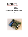
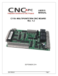
USER’S MANUAL C1- MULTIFUNCTION CNC BOARD Rev. 10.1 June, 2012 USER'S MANUAL TABLE OF CONTENTS Page # Contents 1.0 FEATURES ..................................................................................................................1-1 2.0 SPECIFICATIONS .......................................................................................................2-3 3.0 Board description .......................................................................................................3-4 Outputs 2-9 simplified functional block diagram .............................................................3-4 Outputs 1, 14, 16 and 17 simplified functional block diagram ........................................3-4 Input simplified functional block diagram ........................................................................3-5 Using the COM configuration jumper. ..............................................................................3-5 1-2: COM= 5V ....................................................................................................................3-5 2-3: COM= GND ................................................................................................................3-5 External Enable Pin. ...........................................................................................................3-6 4.0 Wiring ..........................................................................................................................4-7 Connecting Switches or push button. ..............................................................................4-7 Connecting NPN sensors. .................................................................................................4-7 Calculating the R1 value. ...................................................................................................4-9 Connecting PNP sensors. .................................................................................................4-9 Other connection. ............................................................................................................4-10 Using the COM configuration jumper. ............................................................................4-11 5.0 DimensionS...............................................................................................................5-12 6.0 DISCLAIMER: ............................................................................................................6-12 User’s Manual Page i 1.0 FEATURES IEEE 1284 Standard compatible. Includes the circuitry recommended by the IEEE 1284 Level 1 standards for bidirectional parallel communications between personal computers and peripherals PULL-UP or PULL-DOWN selection for inputs. Includes jumpers to select the best input configuration for your application. Fully optosiolated The card isolates connections to protect your computer from short-circuit. An opto-isolator is an integrated circuit that transmits the signal through an encapsulated LED and phototransistor. When the signal is on, the LED lights up, the phototransistor captures it and relays the signal. The signals are transmitted through light and not through physical connections. In this way, a power surge has no way of reaching your computer. That is the reason why this card has two power connections. One power connection is power powering the circuit that interacts with the PC, the other connection is for powering the circuit that interacts with your CNC system. Extra precautions have been taken when designing this circuit, by taking into consideration the extremely high voltages that stepper drivers can achieve and lack of experience that some users could have in wiring circuits of this kind. This board keeps the grounds of the PC isolated from the grounds of the rest of your CNC circuit. Easy installation of an On/Off switch. You can control the card externally. An On/Off or a Safety Charge Pump can easily be installed to enable or disable the card. CNC machines could be dangerous and, remember, safety comes first. This card is provided with an extra pin (EN) that allows you to control the card externally by enabling or disabling outputs. The card must have +5vdc supplied to the EN terminal to enable outputs. Support for up to 1MHz optoisolation on step and direction signals. New on this revision is that the optoisolation circuit has been optimized and now supports full optoisolation at speeds up to 1MHz. Status LEDs on all inputs and output connections. User’s Manual Page 1-1 No more guessing. You can SEE all your signals. Save valuable time and brainpower for CNCing. To avoid remaining current to the main load (driver or other device), all the indicator LEDs are driven by independent buffers of the ones that drive de output. Built-in Passive Low Pass Filters for the all signal. This board includes low pass filters to reduce the effect of the noise from the drivers or other devices over the signals. Has an extra DB25 female connection for output. You can use this card to optoisolate any existing setup just by connecting this card between your computer and your current setup. That way, you can also see and access all your signals. This makes this card ideal for use with the Xylotex, HobbyCNC or other non-optoisolated boards. You only have to add this board to a DB25 male connection to a male cable. All TTL 5VDC signals. Interface directly with parallel port interface products and other CNC4PC cards. 5VDC (TTL) cards are very common among automation devices. Buffered outputs. All outputs are buffered through the use of high speed and high current buffers, with the result that your devices receive all the power they need. Input and output pins with close by ground connections. Forget about grounding problems. Easily connect your pin by using your close by ground connection. No need to be an electronics expert to ground all your stuff. The terminals next to pins 2-9 can be set to have +5VDC or GND according to your needs. There is a jumpers that allows you to select +5VDC or GND for the COM pins. Works directly with popular CNC hardware and software. That goes for Smooth Stepper Geckdrive, Leadshine, Viper and parallel port control software such as Mach3, Linux EMC, TurboCNC and other/ (Not all have been tested). User’s Manual Page 1-2 2.0 Screw-On connections for all terminals. You only have to screw-on the wires to make all your connections SPECIFICATIONS DIGITAL INPUT SPECIFICATIONS Numbers of inputs 5 On-state voltage range 2 to 5V DC Maximum off-state voltaje 0.8V Typical signal delay 2.8uS DIGITAL OUTPUT SPECIFICATIONS Number of outputs 12 (5V power supply voltage) + Maximum output voltage 0.5V Typical output current 24mA Maximum off-state voltaje 0.44 V 1M (pins 2-9), 150KHz (other Maximum supported frequency pins) Typical signal delay 3uS Time of transition to high impedance state 120mS* Time passed since a fault in the SCHP signal is detected and the outputs are disabled. User’s Manual Page 2-3 3.0 BOARD DESCRIPTION Outputs 2-9 simplified functional block diagram Fig. 1 Simplified functional block diagram for the outputs 2-9. Parallel Port coupling is done following IEEE 1284 standard recommendation. An RC Low Pass filter followed by a Schmitt Trigger gate is used to help reduce the effect of the noise from drivers or other devices. LEDs are driven by a different buffer to avoid residual currents affecting the signal. Outputs 1, 14, 16 and 17 simplified functional block diagram Fig. 2 Simplified functional block diagram for the outputs 1, 14, 16 and 17. Note: The outputs will be deactivated if the board is not connected to the PC parallel port. User’s Manual Page 3-4 Input simplified functional block diagram Fig. 3 Simplified functional block diagram for the inputs. Pins 10, 11, 12, 13 and 15 can be set to pull-down or pull-up by selecting the jumper in the appropriate position. 1-2: PULL-UP 2-3: PULL- DOWN Using the COM configuration jumper. There is a jumper (X7) that allows you to select +5VDC or GND for the COM pins. 1-2: COM= 5V 2-3: COM= GND User’s Manual Page 3-5 External Enable Pin. The card must be provided with a 5VDC signal to enable operation. This feature has been added to externally control the status of the outputs. An external switch or a Safety Charge Pump can be added to provide the enabling signal. When the enable signal is not present, output signals sent high impedance state. If this function is not required, an jumper can be placed between +5vdc and the EN terminal. It has an internal 4.7kOhm pull-down resistor. WARNING: This card must have the power supplied while it is connected to the PC. If power is removed to the card while it is connected to the PC, noise can be introduced to the output lines. This can create a dangerous situation as relays or other devices that might be connected to this card could get activated. User’s Manual Page 3-6 4.0 WIRING While this board supports only TTL +5VDC signals, different kind of sensors, switches using different voltages can be connected using the diagrams that follow: Note: The bellow wiring diagrams are examples. Any input can be used for the connections. Note. The bellow wiring diagrams require setting the inputs to use pull-down resistor. Connecting Switches or push button. Fig. 7 Wiring diagram to connect switches. Connecting NPN sensors. Fig. 8 Wiring diagram to connect NPN open collector proximity sensors. User’s Manual Page 4-7 Fig. 9 Wiring diagram to connect in parallel NPN open collector proximity sensors. Connecting NPN open collector proximity sensor with the C1 R1 Value (12V) R1 Value (24V) Aprox. 10KΩ Aprox. 25KΩ Fig. 10 Wiring diagram to connect NPN proximity sensors with internal pull up resistor. Some NPN proximity sensor has a pull-up resistor (R1) internally. It is necessary to know its value in order to connect safely the sensor with the BOB. Follow this recommendation: User’s Manual Page 4-8 Connecting NPN open collector proximity sensor with the C1 (R1+R2) Value (12V) (R1+R2) Value (24V) Aprox. 10KΩ Aprox. 25KΩ Calculating the R1 value. Note: Rx is the unknown resistor value. Where: VEX is the external power supply voltage V is the voltage across the R resistor An external resistor and a voltmeter are required to calculate the internal resistor (Rx) value. Note. The user should know the R value to do this operation. A 4.7KOhm @ 1/2W is recommended. SAMPLE: if you are using a 12V power supply (VEX), and using a 4.7KOhm as external resistor (R), then the voltage across R should be 6V, using the equation 1, the Rx value is 4.7KOhm. Connecting PNP sensors. User’s Manual Page 4-9 Fig. 11 Wiring diagram to connect PNP proximity sensors Connecting PNP proximity sensor with the C1 R Value (12V) R Value (24V) Aprox. 10KΩ Aprox. 25KΩ Other connection. Other connections can be implemented by setting the inputs to pull-up resistor. Fig. 12 Wiring diagram to do an “Auto Tool Zero” http://cnc4pc.com/Tech_Docs/E_STOP_N_EN_Wiring.pdf http://cnc4pc.com/Tech_Docs/E_STOP_N_SCHP.pdf User’s Manual Page 4-10 Using the COM configuration jumper. This is for selecting the value to get at the COM terminals found next to step and direction terminals (Pin 2-9). Some drivers expect a ground, and others expect +5vdc. There is a jumper that allows you to select +5VDC or GND for the COM pins. 1-2: COM= +5V 2-3: COM= GND User’s Manual Page 4-11 5.0 DIMENSIONS All dimension are in Millimeters 6.0 DISCLAIMER: Use caution. CNC machines could be dangerous machines. DUNCAN USA, LLC or Arturo Duncan are not liable for any accidents resulting from the improper use of these devices. This product is not fail-safe device, and it should not be used in life support systems or in other devices where its failure or possible erratic operation could cause property damage, bodily injury or loss of life. User’s Manual Page 6-12