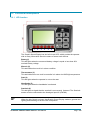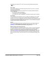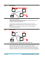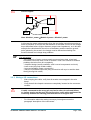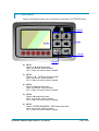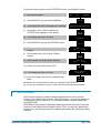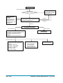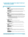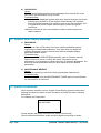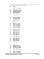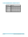
1
ELECTRONIC • OLEODYNAMIC • INDUSTRIAL
EQUIPMENTS CONSTRUCTION
Via Parma, 59 – 42028 – POVIGLIO (RE) – ITALY
Tel +39 0522 960050 (r.a.) – Fax +39 0522 960259
e-mail: [email protected] – web: www.zapispa.it
EN
User Manual
GRAPHIC
SMART
DISPLAY
Copyright © 1975-2009 Zapi S.p.A.
All rights reserved
The contents of this publication is a ZAPI S.p.A. property; all related authorizations are covered
by Copyright. Any partial or total reproduction is prohibited.
Under no circumstances will Zapi S.p.A. be held responsible to third parties for damage caused
by the improper use of the present publication and of the device/devices described in it.
Zapi spa reserves the right to make changes or improvements to its products at any time and
without notice.
The present publication reflects the characteristics of the product described at the moment of
distribution. The publication therefore does not reflect any changes in the characteristics of the
product as a result of updating.
is a registered trademark property of Zapi S.p.A.
NOTES LEGEND
4
U
Page - 2/43
The symbol aboard is used inside this publication to indicate an annotation or a
suggestion you should pay attention.
The symbol aboard is used inside this publication to indicate an action or a
characteristic very important as for security. Pay special attention to the
annotations pointed out with this symbol.
AF4ZP0AB - GRAPHIC SMART DISPLAY - User Manual
Contents
1
2
3
4
5
6
7
8
9
INTRODUCTION ...................................................................................................................5
GENERAL CHARACTERISTICS ..........................................................................................6
2.1
Technical specifications..............................................................................................6
2.1.1
Dashboard ....................................................................................................6
2.1.2
Alphanumeric LCD (Liquid Crystal Display)..................................................6
2.2
Functional descriptions ...............................................................................................7
2.2.1
LED function .................................................................................................7
2.2.2
Display function.............................................................................................8
INSTALLATION HINTS.......................................................................................................10
3.1
Material overview......................................................................................................10
3.1.1
Connection cables ......................................................................................10
3.1.2
Fuses ..........................................................................................................10
3.2
Installation of the hardware.......................................................................................10
3.2.1
Dashboard heating......................................................................................11
3.2.2
Wirings: CAN connections and possible interferences ...............................11
3.2.3
Wirings: I/O connections .............................................................................13
3.2.4
Insulation of truck frame..............................................................................14
3.3
Protection and safety features ..................................................................................14
3.3.1
Protection features......................................................................................14
3.3.2
Safety Features...........................................................................................14
3.4
EMC..........................................................................................................................15
DIAGNOSIS.........................................................................................................................17
DESCRIPTION OF CONNECTORS....................................................................................18
5.1
CNA connector: Molex Minifit 6 pins .........................................................................18
5.2
CNB connector: Molex Minifit 4 pins .........................................................................18
5.3
CNC connector: Molex Minifit 12 pins.......................................................................18
DRAWINGS .........................................................................................................................20
6.1
Mechanical drawing ..................................................................................................20
6.2
Connection drawing ..................................................................................................21
PROGRAMMING AND ADJUSTMENTS USING ZAPI HANDSET ....................................22
7.1
Adjustment via console.............................................................................................22
7.2
Description of standard console menu .....................................................................23
7.3
Description of programmable functions ....................................................................24
7.4
Special Adjustment menu .........................................................................................26
7.5
Hardware Setting .....................................................................................................26
7.6
Tester menu..............................................................................................................27
7.7
Description of console using.....................................................................................29
7.8
Other functions .........................................................................................................31
7.9
Description of Alarm menu .......................................................................................32
STRUCTURE OF DISPLAY MENU.....................................................................................33
8.1
Performance rolling...................................................................................................35
8.2
Using of Password menu..........................................................................................35
8.3
Using dashboard like a console................................................................................36
8.4
Set Date/Hour menu .................................................................................................36
ANALYSIS OF GRAPHIC SMART DISPLAY RELATED ALARMS ..................................37
9.1
Graphic Smart Display alarms ..................................................................................37
9.2
Graphic Smart Display warnings ..............................................................................38
AF4ZP0AB - GRAPHIC SMART DISPLAY - User Manual
Page - 3/43
9.3
Alarms visualisation.................................................................................................. 38
10 RECOMMENDED SPARE PARTS ..................................................................................... 42
11 PERIODIC MAINTENANCE TO BE REPEATED AT TIMES INDICATED......................... 43
APPROVAL SIGNS
COMPANY FUNCTION
INIZIALS
PROJECT MANAGER
FG
TECHNICAL ELECTRONIC
MANAGER VISA
PP
SALES MANAGER VISA
MC
SIGN
Publication N°: AF4ZP0AB
Edition: May 2009
Page - 4/43
AF4ZP0AB - GRAPHIC SMART DISPLAY - User Manual
1 INTRODUCTION
Graphic Smart Display is an intelligent dashboard connected to the truck system
by CAN-BUS line.
This dashboard provides the diagnostic and set-up of the whole truck system:
Graphic Smart Display itself, Traction controller, Pump controller, Valves
controller.
It has an alphanumeric liquid crystal display (LCD) and a built-in backlight.
Access to Graphic Smart Display menu structure is provided by six operator
buttons integrated in a membrane keyboard.
Furthermore this dashboard has six built-in red LED, which provide the operator
with a easy information about the status of some truck devices.
AF4ZP0AB - GRAPHIC SMART DISPLAY - User Manual
Page - 5/43
2 GENERAL CHARACTERISTICS
2.1 Technical specifications
2.1.1 Dashboard
Voltage:..............................................................................................24/36/48/80 V
Can interface [n°]: .................................................................................................. 1
Keyboard buttons [n°]: ........................................................................................... 6
LED [n°]: ................................................................................................................ 6
Protection:…………………………………………………IP65 (Front); IP55 (Bottom)
External temperature range: standard version ........................................-10÷50 °C
External temperature range: frozen cell version ......................................-30÷50 °C
2.1.2 Alphanumeric LCD (Liquid Crystal Display)
Viewing area (WxH).......................................................................... 67.0x46.0 mm
Number of pixels [n°] ................................................................................. 240x160
Pixel size........................................................................................... 0.28x0.28 mm
Yellow-green backlight: number of LED .............................................................. 12
Page - 6/43
AF4ZP0AB - GRAPHIC SMART DISPLAY - User Manual
2.2 Functional descriptions
2.2.1 LED function
1
2
3
4
5
6
The Graphic Smart Display has six built-in red LED, which provide the operator
with an easy information about the status of some truck devices.
Battery(1)
This led lights when the measured battery voltage is equal or less than 40%
nominal battery voltage.
Wrench (2)
This led blinks when truck is in alarm condition.
Thermometer (3)
This led blinks when one truck’s controller is in alarm due IMS high temperature.
Seat (4)
This led lights when the operator is not on the seat.
Handbrake (5)
This led lights when the handbrake is activated.
Seat belt (6)
This led lights to signal that the seat belt is not correctly fastened. The Seat belt
sensor must be connected to the Analogue Input #2 (CNC#8).
4
When the Key Switch is closed, the Graphic Smart Display makes a general test
lighting and switching off all the LED in sequence.
AF4ZP0AB - GRAPHIC SMART DISPLAY - User Manual
Page - 7/43
2.2.2 Display function
2
6
1
7
8
3
4
5
9
Battery’s state of charge
The battery's state of charge indication (number 1 in figure) is displayed on the
left side of the unit; it is shown by ten notches. Each notch represents the 10% of
the battery charge. As the battery becomes discharged, the notches turn off
progressively, one after the other, in proportion to the value of the residual
battery charge. When the residual battery charge is ≤ 40 % the notches displayed
start to blink. When Battery Low alarm appears on the traction controller, the
battery symbol wich is near the notches also blinks.
Performance
The letter which appears in the rectangle displayed in the top right side of the unit
(number 2 in figure) shows the performance mode which is being used in the
controller.
Performances can be scrolled pressing button ESC . When one performance is
selected, the related information will be sent via can-bus to traction and pump
controllers that will manage this data. The standard functioning reduces truck
performance passing from the high to economic performance.
The real meaning, in terms of parameters level of these performances, depends
on software present on pump and traction controllers:
- “H” corresponds to highest performance;
- “N” corresponds to normal performance;
- “E” corresponds to low-economic performance;
Turtle
The turtle symbol (number 3 in figure) is normally off; when it appears (fixed) it
shows activation of the “soft” mode of the truck, in which maximum speed and
Page - 8/43
AF4ZP0AB - GRAPHIC SMART DISPLAY - User Manual
acceleration are reduced. The “soft” mode can be activated pressing button
(↓).
Hour meter
The number displayed on the bottom right side of the unit (number 4 in figure)
shows the Hours Worked.
The letter present near the hour meter(number 5 in figure) shows which hour
meter is displayed:
- K: the key hour meter is displayed;
- T: the traction hour meter is displayed;
- P: the pump hour meter is displayed; it increases if pump control is working.
Accelerator
The accelerator level indication (number 6 in figure) is displayed on the central
top side of the unit; it is shown by ten notches. When the accelerator level is
minimum only a notch is displayed, when the accelerator level is maximum all the
ten notches are displayed. Each notch represents 1/10 of the difference between
maximum and minimum accelerator level.
Speed
The number displayed under the accelerator notches on the center of the unit
(number 7 in figure) shows the truck speed. The unit can be km/h or mph
depending on the SPEED UNIT parameter setting (see 7.4).
Wheel position and running direction
The notch displayed on the left of the hour meter (number 8 in figure) represents
the wheel (only one of the nine notches is displayed) and shows the steering
angle (it corresponds to the relative truck direction if the truck is running).
The arrow (number 9 in figure) shows the set truck running direction. The arrow
point is up when the truck is forward running; the arrow point is down when the
truck is reverse running. If the truck doesn’t run a dot is displayed instead of the
arrow.
AF4ZP0AB - GRAPHIC SMART DISPLAY - User Manual
Page - 9/43
3 INSTALLATION HINTS
In the description of these installation suggestions you will find some boxes of
different colours, they mean:
4
U
These are information useful for anyone is working on the installation, or a
deeper examination of the content
These are Warning boxes, they describe:
- operations that can lead to a failure of the electronic device or can be
dangerous or harmful for the operator;
- items which are important to guarantee system performance and safety
3.1 Material overview
Before starting it is necessary to have the required material for a correct
installation. Otherwise a wrong choice of cables or other parts could lead to
failures/ misbehaviour/ bad performances.
3.1.1 Connection cables
For the auxiliary connections, use cables of 0.5-1.0 mm² section.
3.1.2 Fuses
-
Use a 10A Fuse for protection of the card.
For Safety reasons, we recommend the use of protected fuses in order to
prevent the spread of fused particles in case the fuse blow.
3.2 Installation of the hardware
U
Before doing any operation, ensure that the battery is disconnected and
when all the installation is completed start the machine with the drive
wheels raised from the floor to ensure that any installation error do not
compromise safety.
Do not connect the module to a battery with a nominal voltage different
than the value indicated on the label. A higher battery voltage may cause a
logic failure. A lower voltage may prevent the logic from operating.
Page - 10/43
AF4ZP0AB - GRAPHIC SMART DISPLAY - User Manual
3.2.1 Dashboard heating
Graphic Smart Display does not need any means of heat dissipation. The frozencell version, provided with a built-in heater, is strongly recommended for frozencell applications.
3.2.2 Wirings: CAN connections and possible interferences
4
CAN stands for Controller Area Network. It is a communication protocol for real
time control applications. CAN operates at data rate of up to 1 Megabits per
second.
It was invented by the German company Bosch to be used in the car industry to
permit communication among the various electronic modules of a vehicle,
connected as illustrated in this image:
-
-
The best cable for can connections is the twisted pair; if it is necessary to
increase the immunity of the system to disturbances, a good choice would be
to use a cable with a shield connected to the frame of the truck. Sometimes it
is sufficient a simple double wire cable or a duplex cable not shielded.
In a system like an industrial truck, where power cables carry hundreds of
Ampere, there are voltage drops due to the impedance of the cables, and
that could cause errors on the data transmitted through the can wires. In the
following figures there is an overview of wrong and right layouts of the cables
routing.
AF4ZP0AB - GRAPHIC SMART DISPLAY - User Manual
Page - 11/43
U
Wrong Layout:
R
Can Bus
Power cables
Module
1
Module
2
Module
3
R
The red lines are can wires.
The black boxes are different modules, for example traction controller, pump
controller and display connected by canbus.
The black lines are the power cables.
This is apparently a good layout, but can bring to errors in the can line.
The best solution depends on the type of nodes (modules) connected in the
network.
If the modules are very different in terms of power, then the preferable
connection is the daisy chain.
U
Correct Layout:
R
Can Bus
Power cables
Module
1
Module
2
Module
3
R
Note: Module 1 power > Module 2 power > Module 3 power
The chain starts from the –BATT post of the controller that works with the highest
current, and the others are connected in a decreasing order of power.
Otherwise, if two controllers are similar in power (for example a traction and a
pump motor controller) and a third module works with less current, the best way
to deal this configuration is to create a common ground point (star configuration).
Page - 12/43
AF4ZP0AB - GRAPHIC SMART DISPLAY - User Manual
U
Correct Layout:
R
Can Bus
Power cables
Module
1
Module
2
Center of the Ground connection
Module
3
R
Note: Module 1 power ≈ Module 2 power > Module 3 power
In this case the power cables starting from the two similar controllers must be as
short as possible. Of course also the diameter of the cable concurs in the voltage
drops described before (higher diameter means lower impedance), so in this last
example the cable between the minus of the Battery and the common ground
point (pointed by the arrow in the image) must be dimensioned taking into
account thermal and voltage drop problems.
4
Can advantages
The complexity of today systems needs more and more data, signal and
information must flow from a node to another. CAN is the solution to different
problems that arise from this complexity
- simplified design (readily available, multi sourced components and tools)
- lower costs (less and smaller cables)
- improved reliability (fewer connections)
- analysis of problems improved (easy connection with a pc to read the data
flowing through the cable).
3.2.3 Wirings: I/O connections
-
U
After crimping the cable, verify that all strands are entrapped in the wire
barrel.
Verify that all the crimped contacts are completely inserted on the connector
cavities.
A cable connected to the wrong pin can lead to short circuits and failure;
so, before turning on the truck for the first time, verify with a multimeter the
continuity between the starting point and the end of a signal wire.
-
For information about the mating connector pin assignment see the
paragraph “description of the connectors”.
AF4ZP0AB - GRAPHIC SMART DISPLAY - User Manual
Page - 13/43
3.2.4 Insulation of truck frame
U
As stated by EN-1175 “Safety of machinery – Industrial truck”, chapter 5.7,
“there shall be no electrical connection to the truck frame”. So the truck
frame has to be isolated from any electrical potential of the truck power
line.
3.3 Protection and safety features
3.3.1 Protection features
-
Connection Errors:
All inputs are protected against connection errors.
External agents:
The dashboard is protected against dust and the spray of liquid to a degree
of protection meeting IP55.
3.3.2 Safety Features
U
ZAPI devices are designed according to the prEN954-1 specifications for
safety related parts of control system and to UNI EN1175-1 norm.
The safety of the machine is strongly related to installation; length, layout
and screening of electrical connections have to be carefully designed.
ZAPI is always available to cooperate with the customer in order to evaluate
installation and connection solutions. Furthermore, ZAPI is available to
develop new SW or HW solutions to improve the safety of the machine,
according to customer requirements.
Machine manufacturer holds the responsibility for the truck safety features
and related approval.
Page - 14/43
AF4ZP0AB - GRAPHIC SMART DISPLAY - User Manual
3.4 EMC
U
EMC and ESD performances of an electronic system are strongly
influenced by the installation. Special attention must be given to the
lengths and the paths of the electric connections and the shields. This
situation is beyond ZAPI's control. Zapi can offer assistance and
suggestions, based on its years experience, on EMC related items.
However, ZAPI declines any responsibility for non-compliance,
malfunctions and failures, if correct testing is not made. The machine
manufacturer holds the responsibility to carry out machine validation,
based on existing norms (EN12895 for industrial truck; EN50081-2 for other
applications).
EMC stands for Electromagnetic Compatibility, and it represents the studies and
the tests on the electromagnetic energy generated or received by an electrical
device.
So the analysis works in two directions:
1) The study of the emission problems, the disturbances generated by the
device and the possible countermeasure to prevent the propagation of that
energy; we talk about “conduction” issues when guiding structures such as
wires and cables are involved, “radiated emissions” issues when it is studied
the propagation of electromagnetic energy through the open space. In our
case the origin of the disturbances can be found inside the controller with the
switching of the mosfets which are working at high frequency and generate
RF energy, but wires and cables have the key role to propagate the
disturbs because they works as antennas, so a good layout of the cables
and their shielding can solve the majority of the emission problems.
2) The study of the immunity can be divided in two main branches: protection
from electromagnetic fields and from electrostatic discharge.
The electromagnetic immunity concern the susceptibility of the controller
with regard to electromagnetic fields and their influence on the correct work
made by the electronic device.
There are well defined tests which the machine has to be exposed to.
These tests are carried out at determined levels of electromagnetic fields, to
simulate external undesired disturbances and verify the electronic devices
response.
3) The second type of immunity, ESD, concerns the prevention of the effects of
electric current due to excessive electric charge stored in an object. In fact,
when a charge is created on a material and it remains there, it becomes an
“electrostatic charge”; ESD happens when there is a rapid transfer from a
charged object to another. This rapid transfer has, in turn, two important
effects:
this rapid charge transfer can determine, by induction, disturbs on the
signal wiring and thus create malfunctions; this effect is particularly
critical in modern machines, with serial communications (canbus)
which are spread everywhere on the truck and which carry critical
information.
in the worst case and when the amount of charge is very high, the
AF4ZP0AB - GRAPHIC SMART DISPLAY - User Manual
Page - 15/43
discharge process can determine failures in the electronic devices; the
type of failure can vary from an intermittently malfunction to a completely
failure of the electronic device.
U
IMPORTANT NOTE: it is always much easier and cheaper to avoid ESD
from being generated, than to increase the level of immunity of the
electronic devices.
There are different solutions for EMC issues, depending on level of
emissions/ immunity required, the type of controller, materials and position
of the wires and electronic components.
4) EMISSIONS. Three ways can be followed to reduce the emissions:
SOURCE OF EMISSIONS: finding the main source of disturb and work
on it.
SHIELDING: enclosing contactor and controller in a shielded box; using
shielded cables;
LAYOUT: a good layout of the cables can minimize the antenna effect;
cables running nearby the truck frame or in iron channels connected to
truck frames is generally a suggested not expensive solution to reduce
the emission level.
5) ELECTROMAGNETIC IMMUNITY. The considerations made for emissions
are valid also for immunity. Additionally, further protection can be achieved
with ferrite beads and bypass capacitors.
6) ELECTROSTATIC IMMUNITY. Three ways can be followed to prevent
damages from ESD:
PREVENTION: when handling ESD-sensitive electronic parts, ensure the
operator is grounded; test grounding devices on a daily basis for correct
functioning; this precaution is particularly important during controller
handling in the storing and installation phase.
ISOLATION: use anti-static containers when transferring ESD-sensitive
material.
GROUNDING: when a complete isolation cannot be achieved, a good
grounding can divert the discharge current through a “safe” path; the
frame of a truck can works like a “local earth ground”, absorbing excess
charge. So it is strongly suggested to connect to truck frame all the
parts of the truck which can be touched by the operator, who is
most of the time the source of ESD.
Page - 16/43
AF4ZP0AB - GRAPHIC SMART DISPLAY - User Manual
4 DIAGNOSIS
Graphic Smart Display microcontroller continuously monitors the output stages
and carries out a diagnostic procedure on the main functions.
Main fault diagnostic function concern: parameter and password memory, canbus
interface, output drivers.
AF4ZP0AB - GRAPHIC SMART DISPLAY - User Manual
Page - 17/43
5 DESCRIPTION OF CONNECTORS
5.1 CNA connector: Molex Minifit 6 pins
A1
-BATT
Power supply negative reference
A2
-BATT
Power supply negative reference
A3
CAN H
Can signal high
A4
CAN L
Can signal low
A5
HEATER+
Heater positive power supply. This input must be
connected to +BATT before the key switch.
A6
KEY
Key input
5.2 CNB connector: Molex Minifit 4 pins
B1
NAUX
Auxiliary load output. The external load is driven to –
Batt.
B2
PAUX
Auxiliary load positive supply. This output is internally
connected to the key through a diode (cathode
connected to CNB#2)
B3
CANT
Internally connected to CNA#4 through a Can-Bus 120
Ohm termination resistance. Connecting CNB#3 to
CNA#3 the termination resistance is inserted between
CAN L and CAN H.
B4
+BATT
Power supply positive reference. This input must be
connected to +BATT before the key switch. CNB#4
supplies Graphic Smart Display also after the Key is
switched OFF for a programmable service time.
5.3 CNC connector: Molex Minifit 12 pins
Page - 18/43
C1
FLASH BOOT
This input is used for the software download through
the microcontroller Asynchronous Serial Interface. To
connect the input to CNC#6 during this operation
otherwise leave it open.
C2
NCLRXD
Serial reception negative
C3
PCLTXD
Serial transmission positive
C4
NCLTXD
Serial transmission negative
C5
GND
Console negative power supply
C6
+12
Console positive power supply
C7
AN/DI 1
Analogue/digital input #1
C8
AN/DI 2
Analogue/digital input #2
C9
AN/DI 3
Analogue/digital input #3
AF4ZP0AB - GRAPHIC SMART DISPLAY - User Manual
C10
AN/DI 4
Analogue/digital input #4
C11
NPOT
Power supply negative reference. It is used as
potentiometer negative.
C12
PAN-IN
Potentiometer positive: 12 V / 5 V output;
keep load > 1kW / 0,5 KW
AF4ZP0AB - GRAPHIC SMART DISPLAY - User Manual
Page - 19/43
6 DRAWINGS
6.1 Mechanical drawing
Page - 20/43
AF4ZP0AB - GRAPHIC SMART DISPLAY - User Manual
6.2 Connection drawing
AF4ZP0AB - GRAPHIC SMART DISPLAY - User Manual
Page - 21/43
7 PROGRAMMING AND ADJUSTMENTS
USING ZAPI HANDSET
7.1 Adjustment via console
Adjustment of Parameters and changes to the display configuration are made
using the Digital Console.
Description of console and connection
Page - 22/43
AF4ZP0AB - GRAPHIC SMART DISPLAY - User Manual
7.2 Description of standard console menu
AF4ZP0AB - GRAPHIC SMART DISPLAY - User Manual
Page - 23/43
7.3 Description of programmable functions
MENU SET MODEL
1) CONNECT TO
Using CANBUS link, every module connected to can net can act as the
“access node” to the canbus net for the external world.
For example the ZAPI hand console (or the PC-Win console) can be
physically connected to one module and, by the canbus, virtually
connected to any other module of the net.
This parameter is used to select the module to which the user wishes to
be connected.
Following the numbers associated to each module in Zapi canbus system
are showed.
Number associated in canbus net
MODULE
01
SICOS
02
TRACTION
03
TRACTION MASTER
04
TRACTION SLAVE
05
PUMP
06
EPS-AC
09
MHYRIO/HVC
16
GRAPHIC SMART DISPLAY
MENU SET OPTIONS
1) PERFORM. ENABLE
It can enable or disable operator changing the truck performances using
button 5
- ON: Enabled operator
- OFF: Not enabled operator
2) PERFORMANCE TYPE
It sets the truck performances.
LEVEL 0 : E (Economic performance)
LEVEL 1 : N (Normal performance)
LEVEL 2 : H (High performance)
3) USER PWD
It sets using of the starting password to main page access.
- ON: Starting password requeste
- OFF: Starting password not requested
4) CONSOLE ENABLE
It can active or disable using of console function
- ON: Console function active
Page - 24/43
AF4ZP0AB - GRAPHIC SMART DISPLAY - User Manual
- OFF: Console function disable
5) SPEED UNIT
It sets the speed unit:
OPTION #1: the speed unit is km/h
OPTION #2: the speed unit is mph
6) HOUR COUNTER
It sets the hour counter displayed.
OPTION #1: the traction hours are displayed
OPTION #2: the displayed hours represent the machine hour counter
managed by the display
7) BRAKE ACT CLS
It sets active logic level of handbrake input (C7)
- ON: Active high input
- OFF: Active low input
8) SEATBELT ACT CLS
It sets active logic level of seat input (C8)
- ON: Active high input
- OFF: Active low input
9) AUX OUTPUT#1
The options are:
PRESENT: An external load is connected between PAUX and
NAUX. The related diagnosis are enabled.
ABSENT: No external load is connected between PAUX and NAUX.
The related diagnosis are disabled.
10) ODOMETER
It shows the distance traveled instead of hourmeter. It's possible to
switch between totale distance and partial distance (trip meter) by
pressing key 4. Keep pressed key 4 to reset trip meter.
MENU ADJUSTMENTS
1) DELAY DISPLAY OFF
This parameter sets the display ON “Service time”. If the CNB#4 is
connected to +Batt after Key-Off the display is still supplied for a
programmable time, follow the table below to choose your temporization:
DELAY DISPLAY
OFF LEVEL
SERVICE TIME
[Sec]
0
1
2
3
4
5
6
7
8
9
1
3
5
7
9
11
13
15
17
20
2) SPEED FACTOR
It adjusts speed coefficient to have the correct truck speed value shown on
the display. This coefficient has to be regulated depending on truck mechanic
characteristics. It is the result of following formula:
Speed Factor = (88 * rr * p) / Ø
Where:
rr = total gearbox reduction ratio
p = number of pair pole of the motor
AF4ZP0AB - GRAPHIC SMART DISPLAY - User Manual
Page - 25/43
Ø = traction wheel diameter expressed in centimeters (cm)
3) AUX VOLTAGE#1
It specifies the percentage of battery voltage supplied to AUX coil to close
the AUXILIARY electro valve. This parameter can be changed in the
range 0% to 100%.
4) CHECK UP TYPE
It defines the truck behaviour when a maintenance is required.
LEVEL 0: the “SERVICE REQUIRED” alarm doesn’t appear
LEVEL 1: the “SERVICE REQUIRED” alarm appears after a time equal to
the hours set in the CHECK UP HOURS parameter
LEVEL 2: the “SERVICE REQUIRED” alarm appears after a time equal to
the hours set in the CHECK UP HOURS parameter and after 50
additional hours the truck speed is reduced
5) CHECK UP HOURS
It defines the hours after which a maintenance is required. It can be adjusted
in the 100 to 1000 hours. The resolution is 100 hours (it can be adjusted in
steps of 100 hours).
6) CHECK UP DONE
It can be ON/OFF. This parameter is normally off. Setting this parameter on
at next key-on, the last maintenance hour-counter resets. This operation
erases the “SERVICE REQUIRED” warnig if it is present and disable
possible reductions.
7.4 Special Adjustment menu
To enter this Zapi hidden menu a special procedure is required. Ask this
procedure directly to a Zapi technician.
Following parameter can be configured in this menu:
1) RESET HOURMETER
It can be ON/OFF. If it is ON it is possible to reset the machine hour-counter.
2) RESET ODOMETER
Normally OFF. Set this parameter ON to reset the total distance at next key
on.
7.5 Hardware Setting
To enter this Zapi hidden menu a special procedure is required. Ask this
procedure directly to a Zapi technician.
Following parameter can be configured in this menu:
1) DISPLAY CONTRAST
It is used to better the display contrast.
Page - 26/43
AF4ZP0AB - GRAPHIC SMART DISPLAY - User Manual
7.6 Tester menu
Status of keyboard buttons can be monitored in real time in the TESTER menu.
Key #1
Key #2
Key #4
Key #3
Key #6
Key #5
2) KEY 1
Status of S keyboard button:
ON = Input active, button pushed
OFF = Input not active, button released
3) KEY 2
Status of T - TURTLE keyboard button:
ON = Input active, button pushed
OFF = Input not active, button released
4) KEY 3
Status of W keyboard button:
ON = Input active, button pushed
OFF = Input not active, button released
5) KEY 4
Status of X keyboard button:
ON = Input active, button pushed
OFF = Input not active, button released
6) KEY 5
Status of PERFORMANCE - ESC keyboard button:
ON = Input active, button pushed
OFF = Input not active, button released
AF4ZP0AB - GRAPHIC SMART DISPLAY - User Manual
Page - 27/43
7) KEY 6
Status of (Enter) keyboard button:
ON = Input active, button pushed
OFF = Input not active, button release
8) ANALOGUE INPUT#1
It display the voltage, in the range [0V, 5V], read on AN1 (CNC#7)
9) ANALOGUE INPUT#2
It display the voltage, in the range [0V, 5V], read on AN2 (CNC#8)
10) ANALOGUE INPUT#3
It display the voltage, in the range [0V, 5V], read on AN3 (CNC#9)
11) ANALOGUE INPUT#4
It display the voltage, in the range [0V, 5V], read on AN4 (CNC#10)
Page - 28/43
AF4ZP0AB - GRAPHIC SMART DISPLAY - User Manual
7.7 Description of console using
Access to SET MODEL menu.
The only parameter present in SET MODEL function is CONNECTED TO.
By setting this parameter, operator can connect ZAPI Console to every ZAPI
product connected to CAN-BUS line. This functionality allows completely control
of every ZAPI product without changing the position of the Console connector.
DISP GRPH
0V
0A
ZP0.00
00000
1)
Opening Zapi Menu
2)
Press ROLL UP & SET UP Buttons to enter
CONFIG MENU
3)
The Display will show: SET MODEL. If another
menu is displayed, press ROLL UP or ROLL
DOWN until SET MODEL appears
4)
Press ENTER to go into the SET MODEL
' % '
' ' '
5)
The display will shows the first option, only
CONNECTED TO option is present in this
menu
CONNECTED TO
16
6)
Press SET UP or SET DOWN buttons in order
to select the desired value for selected option
7)
New desired value appears
CONNECTED TO
9
8)
Press OUT to exit the menu
' ' '
' % '
9)
The Display will ask “ARE YOU SURE?”
10) Press ENTER for YES, or OUT if you do not
accept the changes
11) SET MODEL menu appears
12) Press OUT again. Console now disconnects
and reconnects
13) Display now shows the Opening Zapi Menu of
the ZAPI product corresponding to option
selected at point 7)
AF4ZP0AB - GRAPHIC SMART DISPLAY - User Manual
% ' %
' ' '
CONFIG MENU
SET MODEL
' ' %
' ' %
ARE YOU SURE?
YES=ENTER NO=OUT
' % '
' ' '
' ' '
' % '
CONFIG MENU
SET MODEL
' ' '
' % '
MHYRIO CB ZP 0.00
48V 0A 00000
Page - 29/43
Flow chart showing how to make changes to Option Menu:
DISP GRPH
0V
0A
1)
Opening Zapi Menu
2)
Press ROLL UP & SET UP Buttons to enter
CONFIG MENU
3)
The Display will show: SET MODEL
4)
Press ROLL UP or ROLL DOWN until SET
OPTIONS appears
5) SET OPTIONS menu appears
6)
Press ENTER to go into the SET OPTIONS
menu
7)
The Display will show the first option
8)
Press ROLL UP or ROLL DOWN buttons until
desired option appears
9)
Desired option appears
% ' %
' ' '
CONFIG MENU
SET MODEL
% ' '
% ' '
CONFIG MENU
SET OPTIONS
' % '
' ' '
POWER
SELECTOR
1
% ' '
% ' '
USER PASSWORD
ON
10) Press SET UP or SET DOWN buttons in order
to modify the value for selected option
11) New value for selected option appears
' ' %
' ' %
USER PASSWORD
OFF
' ' '
' % '
12) Press OUT to exit the menu
13) Confirmation request appears
ARE YOU SURE?
YES=ENTER NO=OUT
14) Press ENTER to accept the changes, or press
OUT if you do not accept the changes
' % '
' ' '
15) SET OPTIONS menu appears
16) Press OUT again. Display now shows the
Opening Zapi Menu
Page - 30/43
ZP0.00
00000
' ' '
' % '
CONFIG MENU
SET OPTIONS
' ' '
' % '
AF4ZP0AB - GRAPHIC SMART DISPLAY - User Manual
Flow chart showing how to use the TESTER function of the Digital Console:
DISP GRPH
0V
0A
ZP0.00
00000
1)
Opening Zapi Menu
2)
Press ENTER to go into the MAIN MENU
3)
The Display will show: PARAMETER CHANGE
4)
Press ROLL UP or ROLL DOWN until
TESTER menu appears on the display
5)
The Display will show: TESTER
6)
Press ENTER to go into the TESTER function
' % '
' ' '
7)
The first variable to be tested is shown on the
display
KEY 1
OFF
GND
8)
Press either ROLL UP or ROLL DOWN
buttons
% ' '
% ' '
9)
Next variable for measurement appears
KEY 2
OFF
GND
10) When you have finished press OUT
11) The Display will show: TESTER
12) Press OUT again and return to Opening Zapi
Menu
' % '
' ' '
MAIN MENU
PARAMETER CHANGE
% ' '
% ' '
MAIN MENU
TESTER
' ' '
' % '
MAIN MENU
TESTER
' ' '
' % '
Remember it is not possible to make any changes using TESTER.
All you can do is measure as if you were using a pre-connected multimeter.
7.8 Other functions
SAVE function allows to transfer dashboard parameters to the Pc console
memory (using Zapi PcWin console). With this function, a copy of the display set
of parameters can be retained in a Pc and downloaded to another dashboard
(see RESTORE).
RESTORE function allows to download display parameters from the Pc console
memory to the Graphic Smart Display Eeprom. Thus, a copy of the parameters
stored in a Pc can be downloaded in a dashboard avoiding the parameter setting
operation.
AF4ZP0AB - GRAPHIC SMART DISPLAY - User Manual
Page - 31/43
7.9 Description of Alarm menu
The microprocessor in the controller records the last five Alarms that have
occurred. Items remembered relative to each Alarm are: the code of the alarm,
the number of times the particular Alarm occurred and the Hour Meter count. This
function permits deeper diagnosis of problems as the recent history can now be
accessed.
Flow Chart showing how to use the ALARMS function via the Digital Console:
DISP GRPH
0V
0A
Opening Zapi Menu
2)
Press ENTER to go into the MAIN MENU
3)
The Display will show:
4)
Press ROLL UP or ROLL DOWN until
ALARMS menu appears on the display
5)
The Display will show:
6)
Press ENTER to go into the ALARMS menu
' % '
' ' '
7)
The display will show the most recent alarm
CODE
00005h #02 20°C
8)
Each press of ROLL UP button brings up
following alarms. Pressing ROLL DOWN
returns to the most recent
9)
If an alarm has not occurred, the display will
show: NONE
' % '
' ' '
MAIN MENU
PARAMETER CHANGE
% ' '
% ' '
MAIN MENU
ALARMS
10) When you have finished looking at the alarms,
press OUT to exit the ALARMS menu
11) The Display will ask: “CLEAR LOGBOOK?”
Press ENTER for Yes, or OUT for No
12) Press OUT again and return to Opening Zapi
Menu
Page - 32/43
ZP0.00
00000
1)
% ' '
% ' '
NONE
00000h #00
0°C
' ' '
' % '
CLEAR LOGBOOK?
YES=ENTER NO=OUT
' ' '
' % '
AF4ZP0AB - GRAPHIC SMART DISPLAY - User Manual
8 STRUCTURE OF DISPLAY MENU
Graphic Smart Display present a software structure made by menus and
submenus. It is possible to have access to Graphic Smart Display menu structure
by the six operator buttons integrated in a membrane keyboard.
At turn on the display asks the starting password to have access to the main
page (if “USER PASSWORD” option is ON), otherwise it shows directly the main
page (if “USER PASSWORD” option is OFF).
The main page, if there aren’t alarms, shows battery charge, truck speed (in
Km/h or mph, it depends on “SPEED UNIT” parameter) and key/traction/pump
hour meter (see “HOUR COUNTER” option); if alarms are present it will show
alarm code and node number in which alarm has occurred.
From the main page it is possible to have access to the ALARM page (if alarms
occur) and to MENUS page, that may be USER or SERVICE MENU, it depends
on which password is used.
To enter a password is necessary to push the fourth button (M) of membrane
keyboard when the main page is showed; this will show a entering password
page.
By using user password it’s possible to enter USER MENU which will be
customized depending on customer requests.
By using service password it’s possible to enter SERVICE MENU which presents
three items: “password”, “zapi console” and “date/hour”.
The “password” submenu allows to manage passwords of Graphic Smart Display
software structure. It’s possible to edit, add and delete passwords.
All passwords are optional (ON/OFF option).
The “zapi console” submenu can be accessible only if CONSOLE ENABLE
option is ON. This menu allow user to use dashboard as a real Zapi digital
console connected to one module of canbus net.
The “date/hour” submenu allows to modify and watch the display hour and the
calendar (used for future customized functions).
It follows flow chart diagram of software structure.
AF4ZP0AB - GRAPHIC SMART DISPLAY - User Manual
Page - 33/43
START
Starting Password (if option on)
ALARMS PAGE
If alarms occur
PERFORMANCE
CHOICE
The display send the
chosen performance to
traaction and pump
controllers via can; they
will manage this
information
MAIN PAGE
Button 5
It shows battery charge, hourmeter, trac
speed and active performance.
It shows alarm code and
node number in which
alarm has occurred
Button 6
Button 5
Button 6
PASSWORD REQUEST
User password
Service password
SERVICE MENU
USER MENU
It is possibile to scroll items of service menu by
using buttons 1 and 2. these submenus
PASSWORD, DATE/HOUR and ZAPI
CONSOLE.
Push button 6 to enter the desired menu
(to be customized)
(If Console Enable = ON)
ZAPI CONSOLE
The display will act like a Zapi digital
console.
BUTTON 1 = ROLL UP
BUTTON 2 = ROLL DOWN
BUTTON 3 = SET DOWN
BUTTON 4 = SET UP
BUTTON 5 = OUT
BUTTON 6 = ENTER
Page - 34/43
PASSWORD
DATE/HOUR
(for future applications)
-
USER PASSWORD
ADD PASSWORD
EDIT PASSWORD
DELETE PASSWORD
AF4ZP0AB - GRAPHIC SMART DISPLAY - User Manual
8.1 Performance rolling
From MAIN PAGE using membrane keyboard numbers, it is possible to select
the performance mode which must be used in traction and pump controllers.
Performance can be chosen with button 4, and it is displayed in the top right side
of the unit.
When one performance is selected, the related information will be sent via
canbus to traction and pump controllers that will manage this data. The standard
functioning reduces truck performance passing from high performance mode (H)
to economy performance mode (E).
This is possible only if “PERFORM. ENABLE” option is ON.
The real meaning, in terms of parameters level of these performances, depends
on software present on pump and traction controllers.
Button 4
selects in sequence the truck performance (H → N → E).
8.2 Using of Password menu
By entering the service password from MAIN PAGE it’s possible to have access
to SERVICE MENU. Here with roll buttons (button 1 and 2 of membrane
keyboard) it’s possible to scroll the submenu items.
With ENTER button (button 6 of membrane keyboard) it is possible to enter
PASSWORD submenu where the operator can manage Graphic Smart Display
passwords. In particular it could enable/disable password entering, enter, edit
and remove passwords.
Inside the PASSWORD menu, use buttons ENTER (6) and OUT (5) to enter or
exit submenus and to confirm or cancel operations.
When new password is added, insert:
- the 5 digits password in place of “11111” that appear on the left side of
screen;
- the alphanumeric user id in place of “--------“;
- the performance type 0/1/2 (M) related to the password.
- password type (U): S-service / O-user.
To edit or add passwords use these buttons:
Button 1 / Button 2
Button 3
Button 4
Button 5
Button 6
change the digit marked by cursor
shifts cursor on previous digit
shifts cursor on following digit
cancels all changing
saves all changing
When there isn’t service password in eeprom, it can be used default password
“55555” that is deactivated when at least one service password is saved, and it is
reactivated when all service passwords are deleted, then it is not possible save
the default password.
AF4ZP0AB - GRAPHIC SMART DISPLAY - User Manual
Page - 35/43
8.3 Using dashboard like a console
By entering the service password, from MAIN PAGE it’s possible to have access
to SERVICE MENU. Here with roll buttons (button 1 and 2 of membrane
keyboard) it’s possible to scroll the submenu items.
If option CONSOLE ENABLE is ON, with ENTER button, it is possible to enter
ZAPI CONSOLE submenu, which allows user to use dashboard as a real Zapi
digital console connected to one module of canbus net.
Here with roll buttons (button 1 and 2 of membrane keyboard) and enter button
(button 6), it is possible to choose which module of canbus net has to be
connected to the display.
When the display has been connected, it works exactly like a Zapi digital console.
Buttons of membrane keyboard do the same functions of Zapi console keys.
Button 1
Button 2
Button 3
Button 4
Button 5
Button 6
performs function of the ROLL UP console key
performs function of the ROLL DOWN console key
performs function of the SET DOWN console key
performs function of the SET UP console key
performs function of the OUT console key
performs function of the ENTER console key
8.4 Set Date/Hour menu
By entering the service password from MAIN PAGE it’s possible to have access
to SERVICE MENU. Here with roll buttons (button 1 and 2 of membrane
keyboard) it’s possible to scroll the submenu items.
With ENTER button (button 6 of membrane keyboard) is possible to enter
DATE/HOUR submenu where the operator can watch and modify the date and
the calendar.
Inside the DATE/HOUR menu use buttons ENTER (6) and OUT (5) to enter or
exit submenus and to confirm or cancel operations.
To modify hour and date use these buttons:
Button 1 / Button 2
Button 3
Button 4
Button 5
Button 6
Page - 36/43
change the digit marked by cursor
shifts cursor on previous digit
shifts cursor on following digit
cancels all changing
saves all changing
AF4ZP0AB - GRAPHIC SMART DISPLAY - User Manual
9 ANALYSIS OF GRAPHIC SMART DISPLAY
RELATED ALARMS
9.1 Graphic Smart Display alarms
1) WATCHDOG
Cause:
At start-up the watch dog signal is already active before the software has
generated it. At standby or running condition the watch dog signal is not
active (in alarm status).
Troubleshooting:
The WD hardware circuit or microcontroller output port are damaged. In both
cases no external component are involved. Replace the logic board.
2) COIL SHORTED
Cause:
This alarm occurs when there is a short circuit of the AUXILIARY coil
connected to CNB#1 output. After the overload condition has been removed,
the alarm exits automatically by releasing and then enabling a travel demand.
Troubleshooting:
The typical root cause for this error code to be displayed is in the harness or
in the load coil. So the very first check to carry out concerns connections
between dashboard outputs and loads.
In case no failures/problems have been found externally, the problem is in
the logic card, which has to be replaced.
3) DRIVER SHORTED
Cause:
The driver of the auxiliary electro valve coil is shorted.
Troubleshooting:
Check if there is a short or a low impedance pull-down between NAUX
(CNB#1) and –BATT.
The driver circuit is damaged in the logic board, which has to be replaced.
4) AUX DRIVER OPEN
Cause:
The AUX coil driver is not able to drive the load. The device itself or its
driving circuit is damaged.
Troubleshooting:
This type of fault is not related to external components; replace the logic
board.
5) HARDWARE FAULT
Cause:
At Key-on the dashboard checks if the AUX driver is turned off by a not
active (alarm status) Watch-dog signal. If it is not turned off then the alarm is
generated.
Troubleshooting:
The problem is inside the logic, no external component are involved, replace
the logic board.
AF4ZP0AB - GRAPHIC SMART DISPLAY - User Manual
Page - 37/43
6) CAN BUS KO
Cause:
Graphic Smart Display doesn’t receive messages from canbus line or the
hour meter synchronization at Key-on fails.
Troubleshooting:
If this fault code is displayed together with other alarm messages, the fault is
probably to be looked for in the Graphic Smart Display can interface,
since the Display seems to be unable to receive any can message. So it
is suggested to check Graphic Smart Display canbus wiring and
connection.
Otherwise, the fault is in the can interface of other modules present on
canbus network.
9.2 Graphic Smart Display warnings
1) EEPROM KO
Cause:
It’s due to an HW or SW defect of the non-volatile embedded memory
supporting the dashboard parameters. This alarm does not inhibit the
machine operations, but the truck will work with the Graphic Display
parameters default values.
Troubleshooting:
Try to execute a CLEAR EEPROM operation (refer to Console manual).
Switch the key off and on to check the result. If the alarm occurs
permanently, it is necessary to replace the logic. If the alarm disappears, the
previously stored parameters will have been replaced by the default
parameters.
2) MAINTENANCE NEEDED
Cause:
This is just a warning to call for the time programmed maintenance.
Troubleshooting:
It is just enough to turn the MAINTENANCE DONE option to level ON after
the maintenance is executed.
9.3 Alarms visualisation
When an alarm condition occurs, Graphic Smart Display gives the information
showing the initial of module in which the alarm occurred, the alarm code and
description.
For example, the information:
245 ON PUMP
means that the alarm 245 occurred in the pump controller (M).
Here the table with the alarm codes and the respective meaning is shown.
Page - 38/43
AF4ZP0AB - GRAPHIC SMART DISPLAY - User Manual
The meaning of alarms with a code higher than 99 can change depending on the
purpose of the application (see following tables).
00
NONE
01
CHOPPER RUNNING
02
NO COMMUNICATION
03
UNKNOWN CHOPPER
04
CONSOLE EEPROM
05
SERIAL ERROR #2
06
SERIAL ERROR #1
07
CHOPPER NOT CONF
08
WATCHDOG
09
FIELD FF FAILURE
10
EEPROM DATA KO
11
EEPROM PAR. KO
12
EEPROM CONF. KO
13
EEPROM KO
14
EEPROM OFFLINE
15
LOGIC FAILURE #5
16
LOGIC FAILURE #4
17
LOGIC FAILURE #3
18
LOGIC FAILURE #2
19
LOGIC FAILURE #1
20
FORW VMN LOW
21
FORW VMN HIGH
22
BACK VMN LOW
23
BACK VMN HIGH
24
LEFT VMN LOW
25
LEFT VMN HIGH
26
RIGHT VMN LOW
27
RIGHT VMN HIGH
28
PUMP VMN LOW
29
PUMP VMN HIGH
30
VMN LOW
31
VMN HIGH
32
VMN NOT OK
33
NO FULL COND.
34
RGT NO FULL COND
35
LFT NO FULL COND
36
PU NO FULL COND
37
CONTACTOR CLOSED
38
CONTACTOR OPEN
39
BRAKE CON CLOSED
AF4ZP0AB - GRAPHIC SMART DISPLAY - User Manual
Page - 39/43
Page - 40/43
40
BRAKE CONT. OPEN
41
DIR CONT. CLOSED
42
DIR CONT. OPEN
43
RIGHT CON CLOSED
44
RIGHT CONT. OPEN
45
LEFT CONT CLOSED
46
LEFT CONT. OPEN
47
MAIN CONT CLOSED
48
MAIN CONT. OPEN
49
I=0 EVER
50
LEFT I=0 EVER
51
RIGHT I=0 EVER
52
PUMP I=0 EVER
53
STBY I HIGH
54
LEFT STBY I HIGH
55
RGT STBY I HIGH
56
PUMP STBY I HIGH
57
HIGH FIELD CUR.
58
NO FIELD CUR.
59
HIGH BRAKING I
60
CAPACITOR CHARGE
61
HIGH TEMPERATURE
62
TH. PROTECTION
63
THERMIC LEVEL #2
64
PUMP TEMPERATURE
65
MOTOR TEMPERAT.
66
BATTERY LOW
67
BATTERY LEVEL #2
68
BATTERY LEVEL #1
69
CURRENT SENS. KO
70
HIGH CURRENT
71
POWER FAILURE #3
72
POWER FAILURE #2
73
POWER FAILURE #1
74
DRIVER SHORTED
75
CONTACTOR DRIVER
76
COIL SHORTED
77
COIL INTERRUPTED
78
VACC NOT OK
79
INCORRECT START
80
FORW + BACK
81
BAD STEER 0-SET
AF4ZP0AB - GRAPHIC SMART DISPLAY - User Manual
82
ENCODER ERROR
83
BAD ENCODER SIGN
84
STEER SENSOR KO
85
STEER HAZARD
86
PEDAL WIRE KO
87
PEDAL FAILURE
88
TRACTION BRUSHES
89
PUMP BRUSHES
90
DRIVER 1 KO
91
DRIVER 2 KO
92
DRIVER 1 SIC. KO
93
DRIVER 2 SIC. KO
94
INPUT ERROR #6
95
INPUT ERROR #5
96
INVERTION
97
POSITION HANDLE
98
INPUT ERROR #2
99
INPUT ERROR #1
AF4ZP0AB - GRAPHIC SMART DISPLAY - User Manual
Page - 41/43
10 RECOMMENDED SPARE PARTS
Page - 42/43
Part number
Description
C12359
Molex Minifit Connector 6 pins Female
C12358
Molex Minifit Connector 4 pins Female
C12407
Molex Minifit Connector 12 pins Female
C12777
Female Molex Minifit pin harness side
AF4ZP0AB - GRAPHIC SMART DISPLAY - User Manual
11 PERIODIC MAINTENANCE TO BE
REPEATED AT TIMES INDICATED
Checks should be carried out by qualified personnel only and any replacement
parts used should be original. Beware of NON ORIGINAL PARTS.
The installation of this electronic dashboard should be made according to the
diagrams included in this Manual. Any variations or special requirements should
be made after consulting a Zapi Agent.
The supplier is not responsible for any problem that arises from wiring methods
that differ from information included in this Manual. During periodic checks, if a
technician finds any situation that could cause damage or compromise safety, the
matter should be bought to the attention of a Zapi Agent immediately.
The Agent will then take the decision regarding operational safety of the
machine. Remember that Battery Powered Machines feel no pain.
NEVER USE A VEHICLE WITH A FAULTY ELECTRONIC CONTROLLER
U
IMPORTANT NOTE ABOUT WASTE MANAGEMENT:
This controller has both mechanical parts and high-density electronic parts
(printed circuit boards and integrated circuits). If not properly handled
during waste processing, this material may become a relevant source of
pollution. The disposal and recycling of this controller has to follow the
local laws for these types of waste materials.
Zapi commits itself to update its technology in order to reduce the
presence of polluting substances in its product.
AF4ZP0AB - GRAPHIC SMART DISPLAY - User Manual
Page - 43/43