1
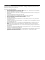
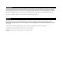
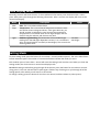
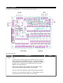
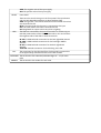
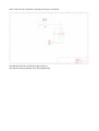
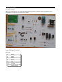
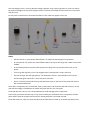
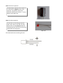
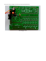
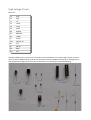
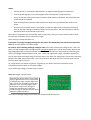
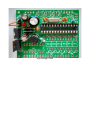
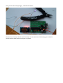
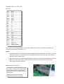
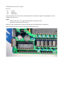
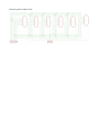
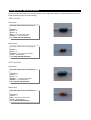
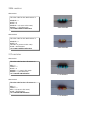
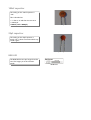
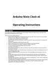
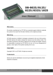
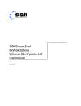
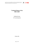
Arduino Nixie Clock v8
Operating Instructions
&
Construction Manual
Document V0008c
Contact Information
If you want to get in contact with me, please email to:
[email protected]
I'll usually get back to you right away.
I can help you with kits or construction.
There are several option packs, complete kits or parts. Just drop us an email.
Direct Purchasing
If you buy through Ebay, I have to pay Ebay commission on top, which is around 10%! The prices here are if
you purchase direct:
•
•
•
•
•
Full Kit of parts with 6 x IN-1 tubes: $79
Full Kit of parts without tubes: $39
Board with “special” components (Atmega 328 pro-programmed and 74141/K155): $20
6 x IN-1 tubes to go with kit: $29
Board only: $9
Postage will be on top. Board and kits without tubes: $3, anything with tubes in it $10. To purchase, contact
me at
[email protected]
or simply make the payment of the amount to my PayPal account:
[email protected]
Description
The Arduino Nixie Clock is a beautiful mix of old and new, resulting in a high accuracy, low power clock
which will be a talking point in your home.
The clock has the following features:
• Battery backed, temperature compensated, high accuracy clock. The accuracy is Accuracy ±2ppm
from 0°C to +40°C. (Maximum 1 minute per year).
• The battery life should be 3 years in normal use.
• Retains the date and time even when turned off (not just for a few minutes, but for as long as the
battery lasts)
• Leap Year Compensation Valid Up to the year 2100
• Based on the Arduino micro-controller: Easy to program an well documented.
• Open source hardware and software. Nothing is hidden in this clock.
• You may modify and load the software with a normal PC
• Low power consumption.
• Anti Cathode Poisoning (ACP) makes sure that the tubes will stay healthy for many years with no
intervention from you.
• All settings are stored in non-volatile memory. Once they are set, they are remembered forever, or
until you change them again.
• RGB back lighting allows you to set the the color of the back lighting to practically any color you
desire.
• Ambient light sensing, with automatic tube dimming, which sets the tube and LED brightness
according to the light conditions. The tubes could be disturbing during the night if they are left at
full brightness.
• Absolutely silent operation. Some Nixie clocks emit an irritating “buzz” or “hiss” which is especially
annoying if you keep the clock in a bedroom.
• Long tube life: The multiplexed display and automatic dimming used in this design extends the life
of the tubes indefinitely. Other designs run the tubes too “hard”, and this causes a rapid
degradation in the useful life of the tube.
General
The clock has different modes of operation, which you select using the pushbutton. When you start the
clock up th very first time, it will start in “Time Display Mode”. We set it up to be the right time for where
the clock is being shipped to, so in the best case you will not even need to set the clock the first time!
The other modes of operation are described in the following sections.
Safety
The voltages produced in the High Voltage circuit can reach peaks of 400V! Take precautions not to
electrocute yourself! If you are not sure what this means, please do not use this clock and return it for a
full refund.
A shock from the clock high voltage circuit is at least a nasty bite. At worst it can kill you.
We decline any responsibility in the case of injury or death.
REPEAT: If you are not sure, please do not use the clock.
Time Display Mode
Normally, the clock will show the time. To show additional information press the button with a “short”
press. Each press cycles through the following information. After 5 seconds, the display will revert to the
normal time display.
Mode
Description
Values
Date
Date. The current date will be shown.
Temp
Temperature. The current internal temperature inside the clock
case will be shown in degrees Celsius. If this goes above 40, you
should consider ventilating the case, because the temperature
compensation is not able to work at such high voltages, and the
clock life may be reduced, and the time may drift.
Light
Ambient Light Reading. This shows the current ambient light
100: dark
reading from the LDR (light dependent resistor). It is a normalized
999: bright
value, and goes between 100 (dark) to 999 (bright). This controls the
dimming of the tubes.
Setting Mode
To enter setting mode, press the button for more than 1 second (“medium press”). The “tick” LED will start
to flash instead of pulse. The number of consecutive flashes indicates the mode you are in.
Each medium press of more than 1 second will move the setting mode onto the next. When you finish the
setting modes, the clock returns to normal time display mode.
To exit the setting mode before going through all the options, press the button for more than 2 seconds
(“long press”). The “tick” LED will start to pulse again. Another way of exiting is to cycle through all of the
setting options, after which you will return to time mode.
To change a setting, press the button for less than one second, and then release it (“short press”).
Mode
Description
Values
Time mode. This is the normal mode and displays the time. It is the
normal start up mode of the clock. If you do nothing. The clock is in
this mode.
In this mode a short press cycles through the values given in “Time
Display Mode”, but always returns to the standard time display after
5 seconds.
Time and Date Settings
Set minutes. Each short press will advance the minute. The
minutes roll over back to 0 ffter reaching 59 minutes. Each time you
set the minute, the seconds is reset to 0.
Set Hours. Each short press will advance the hour. The hours roll
over back to zero after reaching 12 or 24 (depending on the 12/24
hours mode).
Set Day. Each short press will advance the day. The day roll over
back to one after reaching the maximum number of days in the
month.
Set Month. Each short press will advance the month. The month
roll over back to zero after reaching 12.
Set Year. Each short press will advance the year. The year roll over
back to 2015 after reaching 2099.
Basic Settings
“00”
flashing
12 or 24 hour time. The hours are displayed in 12 or 24 hour
mode.
“1” = 12 hour
“0” = 24 hour
“01”
flashing
Blank leading “0”. Blank out the leading “0” from single digit hours. “1” = blank
“0” = don't blank
“02”
flashing
Scroll back. Use the scroll back (rapid count down) effect when
changing from “9” to “0”.
“1” = enable
“0” = disable
“03”
flashing
Date format. Set the format that the date is displayed in.
“0” = YY.MM.DD
“1” = MM.DD.YY
“2” = DD.MM.YY
default: 2
“04”
flashing
Display blanking. To preserve the tubes, you can set the display to
be blanked.
“0” = Don't blank
“1” = Weekends
“2” = Week days
“3” = Always
default: 0
Special Effects Settings
“05”
flashing
Fade Speed Slower. Each short press will make the fade speed
between digits slower.
Default: 50
Max: 200
Min: 20
“06”
flashing
Fade Speed Faster. Each short press will make the fade speed
between digits faster.
Default: 50
Max: 200
Min: 20
“07”
flashing
Scroll-back Speed Slower. Each short press will make the “scrollback” speed slower.
Default: 4
Max: 40
Min: 1
“08”
flashing
Scroll-back Speed Faster. Each short press will make the “scrollback” speed faster.
Default: 4
Max: 40
Min: 1
Back Light Settings
“09”
flashing
Back Light Mode. This sets the mode of the back light.
“Fixed” mode will show the back light color according to the Red,
Green and Blue channel intensities.
“0” = Fixed
“1” = Pulse
“2” = Cycle
default: 0
“Pulse” will make the intensity of the back light “pulse”, brightening
for a second and then darkening for a second, but always
respecting the relative intensities set by the Red, Green and Blue
channel intensities.
“Cycle” fades the back lighting randomly, and does not use the Red,
Green and Blue channel intensities.
“10”
flashing
Red Channel Intensity. Sets the maximum intensity of the red
channel back light. This will be dimmed according to the display
dimming.
Default: 15
Max: 15
Min: 0
“11”
flashing
Green Channel Intensity. Sets the maximum intensity of the green Default: 15
channel back light. This will be dimmed according to the display
Max: 15
dimming.
Min: 0
“12”
flashing
Blue Channel Intensity. Sets the maximum intensity of the blue
channel back light. This will be dimmed according to the display
dimming.
Default: 15
Max: 15
Min: 0
HV Generation Settings (See “HV Settings” note)
“13”
flashing
HV Target Voltage Higher. Each press sets the HV target voltage
higher by 5V.
Default: 180
Max: 200
Min: 150
“14”
flashing
HV Target Voltage Lower. Each press sets the HV target voltage
lower by 5V.
Default: 180
Max: 200
Min: 150
“15”
flashing
PWM On Time Longer. This setting controls how long the PWM On
pulse is. Normally you should not have to change this, but you can
try changing this is the HV generation is noisy or you have unusual
tubes.
Default: 200
Max: 50
Min: 500
“16”
flashing
PWM On Time Shorter. This setting controls how long the PWM On Default: 200
pulse is. Normally you should not have to change this, but you can Max: 50
try changing this is the HV generation is noisy or you have unusual Min: 500
tubes.
Information Settings
“17”
flashing
Current case temperature. Show the current temperature inside
the case (used as part of the temperature compensation for the
clock crystal).
“18”
flashing
Clock version. Show the clock software version. In this version, will
show “0007”.
Digit Test. Will roll through all digits on all locations to check that
the display is healthy.
Note “HV Settings”: Before leaving the clock for long periods with a new “HV Generation” setting, check
that neither the IRF740 MOSFET nor the 7805 voltage regulator is running too hot. If either of these
components gets too hot, either adjust the high voltage settings or add a heat sink.
Display Blanking Mode
During display blanking mode the tubes will be off depending on the display blanking settings, but the
“tick” LED will continue to pulse as usual, telling you that the clock is still running.
You can configure the display to blank at weekends, during week days, always or never (the default).
In order to display the time during blanking, just press the button, and the time will be displayed for the
rest of the minute.
Tube Healing Mode
After a long period of time, tube filaments which are not often used (e.g. the “9” on the tens of hours or
minutes) can get dim, despite the ACP that is regularly done.
If you make a “super-long” press of the button (more than 8 seconds), the clock will enter filament healing
mode. All the power will be placed through a single filament of a single digit to clean it. A short press will
change the selected filament.
Another super-long press or cycling through all the filaments will return the clock to normal.
Caution! Don't leave a single filament in this state for an extended period of time. It is a harsh process,
and may damage the tube if you leave it in this mode for too long. Normally a few minutes will restore the
cathode digit.
Factory Reset
To reset the clock back to initial settings, hold down the button while powering on. The “tick” LED will flash
10 times to signal that the reset has been done.
Everything will be reset back to the factory default state.
External power supply
The perfect voltage for the external power supply is 7.5V or 9V DC. You can use 12V DC.
If you use more than 12V be aware that you might have to provide a heat sink for the power components
and adjust the HV voltage generation. It is not advised to use more than 12V.
The absolute maximum permissible is 24V DC. Higher voltages than this will surely damage the clock.
Board layout
For reference, the board layout is as shown (viewed from the top):
The connections are:
Connector
POWER
Description
Power.
External power should be applied to the board with this connector.
Any DC input source is possible, from 7.5V – 12V. Higher voltages
may be possible, but could cause the digits to flicker is the voltage is
too high, and you might have to provide a heat sink for the the
MOSFET and voltage regulator.
The absolute maximum input voltage is 24V. Any higher voltage
than this will damage the board within a few seconds!
The input is protected against the input being connected reversed.
The input current ranges from 300mA to 1A depending on the size
of the tubes and the number of LEDs you are driving.
Values
GND: The negative side of the input supply
VIN: The positive side of the input supply
FRONT
Front Panel.
These are the controls that go on the front panel: The input button
and the Light Dependent Resistor to detect ambient light.
GND: The “ground”. One lead of the button and one lead of the LDR
are connected to this.
BTN1: The other lead of the button is connected to this input
DLS: The other lead of the LDR is connected to this
VCC: Regulated 5V output to drive any LEDs or lighting.
LEDs
The LEDs are connected to these sink terminals. To connect up you
take the positive sides of the LEDs to either VIN or VCC and connect
the negative sides of the LEDs to these termionals.
BL RED *: PWM cathode connection for the back light RED channel.
BL GRN *: PWM cathode connection for the back light GREEN
channel.
BL BLU *: PWM cathode connection for the back light BLUE
channel.
TICK LED: Cathode connection for the blinking “tick” LED.
RTC
The connection for the RTC (Real Time Clock) module. Connect this
to the approriately marked terminals on the RTC module.
CATHODES The terminals to the cathodes (individual digits “0” - “9”) for each
tube.
ANODES
The terminals to the anodes for each tube.
Schematic
Below is the schematic for the clock.
And for the external components, showing how they are connected.
The LDR and switch are connected to ground (pin 1).
The LEDs are driven preferably from VCC (regulated 5V).
Construction
Kit Contents:
When you unpack the kit, you should find the following contents (note that the exact selection of the
component in the kit can vary from time to time):
Low Voltage Circuit:
Parts List:
D1
IN4001
C2
100nF
IC1
7805TV
C9
220uF
R8
2.7k
LED1
LED3MM
SV1
CONN_POWER
The Low Voltage circuit is a very traditional voltage regulator using a linear regulator. It's job is to reduce
the external voltage from the power adapter down to a known and stable 5V to drive the micro-controller
and the 74141.
Put the parts on the board in the marked locations in the order they appear on the list.
Notes:
•
See the section on “Component Identification” for help with identifying the components.
•
D1 and D2 look very similar, but have different jobs to do. Be careful to get the 1N4001 and not the
UF4004.
•
D1 should be placed so that the white stripe on the body lines up with the white stripe on the
board.
•
C9 must go the right way round. The negative side is marked with a stripe. (See hint)
•
The LED must go with the right polarity. The side with a flat on it, (the cathode, which has the
shorter lead) goes nearest the “170V” test point. (See hint)
•
Put IC1 so that the metal tab lines up with the white stripe on the board. The metal side faces to
the outside of the board.
Once all the components are on the board, hook up the power, and check that the LED comes on. Check
also that the voltage is 5V between the “GND” test point and the “VCC” test point.
If the LED does not come on, turn off immediately to avoid damage to the components.
If all is well, proceed to the next step. If not, check carefully the orientation of the components and the
power leads. Diode D1 protects the board from having the power connected inverted.
If the LED comes on, check for a few seconds that the 7805 does not heat up. It should stay almost cold.
Hint: The 220 uF capacitor
The electrolytic capacitor has a stripe on
it to denote the negative side of the
capacitor. The positive side of the
capacitor (which goes into the “+” on the
board) is the other one!
220uF capacitor “stripe”
Hint: The LED orientation
The LED has one lead longer than the
other, and a flat on one side. The side
with the flat, and the shorter lead (the
cathode) goes into the hole on the board
nearest the 170V test point.
The LED
The LED should look something like this:
At the end of the low voltage circuit build, your board should look like this:
Low Voltage Circuit
High Voltage Circuit:
Parts List:
C5
22pF
C6
22pF
C1
1uF
C7
100nF
C8
100nF
C4
220uF
D2
UF4004
IC2
MEGA8-P
Q2
16MHz
L1
100uH
S24
SOCKET 28
R7
2.7k
Q1
IRF740
R9
390k
R10
4.7k
The high voltage circuit uses the micro-controller to drive the boost circuit with a high frequency square
wave, and has a feedback loop in which the controller reads the voltage produced via an analogue input,
and regulates the brightness of the tubes so that there is no flickering or unwanted dimming.
Notes:
•
See the section on “Component Identification” for help with identifying the components.
•
C4 must go the right way round. The negative side is marked with a stripe (see hint).
•
Put Q1 so that the metal portion lines up with the white stripe on the board. The metal side faces
to the outside of the board.
•
D2 should be placed so that the white stripe on the body lines up with the white stripe on the
board.
•
Put the micro-controller socket in first. Make sure that the depression on the end of the socket
lines up with the marking on the board. When you put the chip in, the chip should go in with the
depression faces to the outside of the board.
Once all the components are on the board, hook up the power. Give your work a careful check to make
sure that the orientation of the components is right.
Then, hold your breath and switch on.
If you hear any angry sounding buzzing turn the power off immediately and check the orientation
of C1! The circuit should run almost silently.
Be careful, we are dealing with high voltages now! If all is well, measure the voltage at the “170V” test
point. It is high voltage and the voltage may be significantly higher than 170V at the moment, because the
high voltage generator is powerful and the output is not loaded. Once you add a load, (by connecting the
tubes), the voltage should oscillate around 170V – 190V, and might have a slight “sawtooth” appearance.
You can also check the voltage using an old neon lamp if you have one. Temporarily connect the neon lamp
between the “GND” test point and the “170V” test point (turn the power off first). Turn the power on and
the neon lamp should come on.
Q1 can get warm, but should not get hot. If it gets hot, you need to check the orientation of the
components and that there are no solder bridges.
If you read a high voltage, proceed to the next step.
Hint: Mounting the 28 pin socket
Mounting the 28 pin socket can be a little
tricky. A good trick is to fix it in place with
a small piece of tape, and the solder one
leg in place. You can hold the socket firm
while you “wet” the solder again, which
will hold the socket firmly enough to
solder the remaining pins. One leg is
usually enough to hold the socket in place
while you solder the others.
Mounting 28 pin socket
At the end of the high voltage circuit build, your board should look like this:
High Voltage Circuit
“TICK LED” Circuit:
Parts List:
RTC
RTC
SV4
CONN_RTC
R19
1k
Q6
2N7000
TICK LED
LED 5mm
SV6
CONN_LED
SV2
CONN_FRONT
This step will check that the Micro-controller can talk to the RTC module, and that the time counting is
working properly. The flashing rhythm of the “tick” LED comes from the RTC module.
Notes:
•
Q6 should be orientated with the flat side as shown on the board. Some FETs come with the leds in
a row rather than in a triange. If this is the case, bend the middle lead slightly so that it fits the
holes in the board (see hint).
•
The RTC module has two sets of contacts on it. You can use either the side with the pins on it or
wire up the other side with flying wires. If you use the side with pins, you should carefully remove
the two unused pins (see hint).
•
The LED must go with the right polarity. The + side has a flat on it, and has the shorter lead (see
hint).
The LED should be wired up with the longer lead to pin 4 of the CONN_FRONT (SV2) connector and the
shorter lead to pin 4 of the CONN_LED (SV3) connector.
Once you have populated the components, power on. The LED on the RTC module should come on, and the
“TICK” LED should flash on and off slowly (on for one second, off for one second).
Hint: Trimming the extra pins on the RTC module
ONLY if you want to mount the RTC
module directly onto the main board (you
can also do it via flying leads), trim off the
pins “32K” and “SQW” using a pair of
precision side cutters.
If you want to mount using flying leads,
you can skip this step and use the four
holes on the other side of the board.
RTC Module with pins removed
Hint: 2N7000 mounting
To mount the 2N7000 FET, bend the
middle lead back slightly. It will then fit in
the PCB without problems.
2N7000
After you have wired everything up, it should look like this:
Note that here I have put the RTC module directly onto the main board. The battery goes in the RTC
module with the back (with the writing on it) upwards.
Anode Control Circuit:
Parts List:
OK1
EL817
OK2
EL817
OK3
EL817
OK4
EL817
OK5
EL817
OK6
EL817
R1
1k
R2
1k
R3
1k
R12
1k
R13
1k
R14
1k
R4
2.7k
R5
2.7k
R6
2.7k
R15
2.7k
R16
2.7k
R17
2.7k
S24
SOCKET 24
SV3
CONN_ANODE
This circuit controls passing the HV to the anodes of the tubes. The micro-controller multiplexes the
anodes by turning each of them on it turn.
Notes:
•
The Opto-Isolators fit into the 24 pin socket snugly. Be careful to put them in the right way round.
The dot denotes pin 1 and should be on the side closest to the micro-controller. All 6 should fit
perfectly into the 24 pin socket.
•
The Opto-Isolators are socketed because they are sensitive to heat and are easily destroyed if you
apply too much heat to them. Putting them in a socket means that we don't run the risk of
destroying them while soldering.
Hint: Putting the resistors in
A trick that can speed assembly up is to
use a piece of normal sticky tape to hold
things in place while you solder them.
This makes is easier to solder and gives a
better result.
Place the components, and then
temporarily tape them into place.
Using tape to hold resistors in place
After you have installed the Anode controls, that part of the board should look this:
Cathode Control Circuit:
Parts List:
IC3
S16
SV5
74141N
SOCKET 16
CONN_DIGIT
This part of the circuit controls which cathode will be lit. Each time the digit to be displayed, the correct
cathodes have to be set.
Notes:
• Instead of the 74141, you might have the Russian equivalent “K155”.
• Be careful to orient the 74141 correctly
Place the 16 pin socket and the connector, and then put the cathode driver on the board.
After you have done this, that part of the board should look like this:
LEDs and front panel
Parts List:
R20
1k (*)
R21
1k (*)
R22
1k (*)
Q3
2N7000
Q4
2N7000
Q5
2N7000
R11
10k
LDR
LDR
S1
SWITCH
LED RGB LED RGB Common anode
These are the final parts of the clock apart from the tubes, and are intended as the elements which the
user sees and touches.
This is the last step of the main board build.
Notes:
• The FETs should be orientated with the flat side as shown on the board. Some FETs come with the
leds in a row rather than in a triange. If this is the case, bend the middle lead slightly so that it fits
the holes in the board (see hint).
•
If you want to run more than one back light LED from the board, see the note below.
(*) You can run more than one back light LED for each R,G or B channel. If you want to do this, replace this
resistor with a simple PCB link, and put a 1k resistor in series with each LED cathode instead. You can run
between 4 and 6 LEDs off the driver depending on the type and the supply (you can choose the regulated
5V or the unregulated VIN). The total current for each channel should not exceed 200mA.
To calculate the current drawn, you can measure the forward drop V FWD across the LED when it is on, and
use the following formula to calculate the current:
ILED = VCC - VFWD / 1k
For example, with a VFWD of 2.2V, the current is:
ILED = 5 – 2.2 / 1k = 2.8mA
In this case, you can safely run 6 LEDs off the channel.
When all the components are installed, you are finished with the board.
The switch connects to ground when closed. It uses the internal pull-up resistor provided by the Atmega on
the input pin to pull the input to VCC when the switch is not closed.
The switch is de-bounced in software, so practically any switch you want to use is suitable. A simple switch
is provided in the kit, but you might want to substitute this switch with one that suits you case.
Connecting the tubes
When all the components are installed, you are now ready to install the tubes. Either you can wire then by
hand or you have a board to put them on. I prefer hand wiring, because I think it has a more “retro” feel.
The anodes are arranged like this:
Anode “1”
Anode “2”
Anode “3”
Anode “4”
Anode “5”
Anode “6”
Hours 10s
Hours
Minutes 10s
Minutes
Seconds 10s
Seconds
Anode “1” is the one next to the tiny “o” on the board connector.
The cathodes are arranged like this:
Cathode “0”
Cathode “1”
Cathode “2”
Cathode “3”
Cathode “4”
Cathode “5”
Cathode “6”
Cathode “7”
Cathode “8”
Cathode “9”
Digit 0
Digit 1
Digit 2
Digit 3
Digit 4
Digit 5
Digit 6
Digit 7
Digit 8
Digit 9
Cathode “0” is next to the tiny “o” on the board connector.
Side note: There are some tricks in the software to make the wiring and the PCB easy and logical. We use a
translation table in the software, and cross some of the standard channels to make the PCB more logical.
You can also see this on the “digit control” section of the schematic. This means that we are not using the
74141 “0” output to drive digit “0”, but instead we are using digit “2” of the 74141 to drive digit “0”.
In the code (available on GitHub), we see this:
// Used for special mappings of the 74141 -> digit (wiring aid)
// allows the board wiring to be much simpler<
int decodeDigit[16] = {2,3,7,6,4,5,1,0,9,8,10,10,10,10,10,10};
When we come in with a “0”, we decode this to “2” (the 0 th element of the array), and in fact, it is the “2”
output that is activated, but the wiring brings the “2” output to the “0” connection.
The cathodes to the tubes (the digits for each tube) need to be wired in parallel, “daisy chaining” them, so
that the run to the same digit of each tube.
The anodes run exactly one tube each.
The wiring for the tubes is this:
Component Identification
We can't always guarantee to get exactly the the same components. Where we have alternatives, they are
listed separately under the same heading.
10k resistor
Alternative 1
The color code for the 10k resistor is:
BROWN = 1
BLACK = 0
BLACK = 0
RED = 2 (2 zeros in this case)
BROWN = 1 (1% Tolerance)
= 1 0 0 0 0 with 1% tolerance
10k resistor
Alternative 2
The color code for the 10k resistor is:
BROWN = 1
BLACK = 0
ORANGE = 3 (3 zeros in this case)
GOLD = 5% Tolerance
= 1 0 0 0 0 with 5% tolerance
10k resistor
4.7k resistor
Alternative 1
The color code for the 4.7k resistor is:
YELLOW = 4
VIOLET = 7
BLACK = 0
BROWN = 1 (1 zero in this case)
BROWN = 1 (1% Tolerance)
= 4 7 0 0 with 1% tolerance
4.7k resistor
Alternative 2
The color code for the 4.7k resistor is:
YELLOW = 4
VIOLET = 7
RED = 2 (2 zeros in this case)
GOLD = 5% Tolerance
= 4 7 0 0 with 5% tolerance
4.7k resistor
390k resistor
Alternative 1
The color code for the 390k resistor is:
ORANGE = 3
WHITE = 9
BLACK = 0
ORANGE = 3 (3 zeros in this case)
BROWN = 1 (1% Tolerance)
= 3 9 0 0 0 0 with 1% tolerance
390k resistor
Alternative 2
The color code for the 390k resistor is:
ORANGE = 3
WHITE = 9
YELLOW = 4 (4 zeros in this case)
GOLD = 5% Tolerance
= 3 9 0 0 0 0 with 5% tolerance
390k resistor
2.7k resistor
Alternative 1
The color code for the 2.7k resistor is:
RED = 2
VIOLET = 7
BLACK = 0
BROWN = 1 (1 zero in this case)
BROWN = 1 (1% Tolerance)
= 2 7 0 0 with 1% tolerance
2.7k resistor
Alternative 2
The color code for the 2.7k resistor is:
RED = 2
VIOLET = 7
RED = 2 (2 zeros in this case)
GOLD = 5% Tolerance
= 2 7 0 0 with 5% tolerance
2.7k resistor
100nF capacitor
The coding on the 100nF capactor is
“104”.
This is decoded as:
= “1” then a “0” and then 4 more zeros
= 100000 pF
= 100 nF (1 nF = 1000 pF)
100nF capacitor
22pF capacitor
The coding on the 22pF capactor is
simply “22”. It does not matter which way
round it goes.
22pF capacitor
RGB LED
The RGB LED has one pin longer than the
rest. This longer pin is the common
anode.
RGB LED
Revisions:
V0007a: 20May2015: Change C4 and C9 to 220uF
V0008a: 06Jun2015: Add HV target voltage setting.
V0008b: 09Jun2015: Clarify input voltage requirements.
V0008c: 17Jun2015: Correct LED orientation.