1
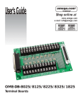
DB-8025/8125/ 8225/8325/1825 User Manual Version 1.5 August 2011 Warranty All products manufactured by ICP DAS are warranted against defective materials for a period of one year from the date of delivery to the original purchaser. Warning ICP DAS assumes no liability for damages consequent to the use of this product. ICP DAS reserves the right to change this manual at any time without notice. The information furnished by ICP DAS is believed to be accurate and reliable. However, no responsibility is assumed by ICP DAS for its use, nor for any infringements of patents or other rights of third parties resulting from its use. Copyright Copyright © 2011 by ICP DAS. All rights are reserved. Trademark Names are used for identification only and may be registered trademarks of their respective companies. DB-8025/8125/8225/8325/1825 Terminal Board User Manual (Ver.1.5, Aug. 2011) 1 Tables of Contents DB-8025 FOR 20-PIN CONNECTOR A/D CARD ........................................................................4 1. ACCESSORIES ............................................................................................................................4 1.1. DB-8025 LAYOUT ..................................................................................................................4 1.2. PIN ASSIGNMENT....................................................................................................................5 1.3. WRING DIAGRAM ...................................................................................................................6 1.4. CAPACITOR FILTER, VOLTAGE DIVIDER AND CURRENT INPUT ................................................6 1.4.1 Input R/C Filtering.................................................................................................................6 1.4.2 Voltage Divider ......................................................................................................................7 1.4.3 Current Input..........................................................................................................................7 DB-8125 FOR 20-PIN OR 37-PIN D-SUB CONNECTOR A/D CARD ........................................8 2. ACCESSORIES ............................................................................................................................8 2.1. DB-8125 LAYOUT ..................................................................................................................8 2.2. PIN ASSIGNMENT....................................................................................................................9 2.3. WRING DIAGRAM .................................................................................................................10 2.4. CAPACITOR FILTER, VOLTAGE DIVIDER AND CURRENT INPUT ..............................................10 2.4.1 Input R/C Filtering...............................................................................................................10 2.4.2 Voltage Divider .................................................................................................................... 11 2.4.3 Current Input........................................................................................................................ 11 DB-8225 FOR A-82X SERIES CARD ..........................................................................................12 3. ACCESSORIES ..........................................................................................................................12 3.1. DB-8225 LAYOUT ................................................................................................................12 3.2. CJC JUMPER SETTING ..........................................................................................................13 3.2.1 Single-End Mode..................................................................................................................13 3.2.1 Differential Mode .................................................................................................................13 3.3. WIRING DIAGRAM ................................................................................................................14 3.3.1 Single-End Connection ........................................................................................................14 3.3.2 Differential Connection........................................................................................................14 3.4. CJC OUTPUT ........................................................................................................................15 3.5. OPEN DETECT AND INPUT FILTERING ...................................................................................16 DB-8025/8125/8225/8325/1825 Terminal Board User Manual (Ver.1.5, Aug. 2011) 2 3.6. VOLTAGE DIVIDER AND CURRENT INPUT .............................................................................17 3.6.1 Voltage Divider ....................................................................................................................17 3.6.2 Current Input........................................................................................................................17 3.7. CN3 TIMER COUNTER AND D/A OUTPUT CONNECTOR ........................................................18 DB-8325 FOR ISO-813 AND PISO-813 ISOLATED A/D CARD ...............................................19 4. ACCESSORIES ..........................................................................................................................19 4.1. DB-8325 LAYOUT ................................................................................................................19 4.2. WRING DIAGRAM .................................................................................................................20 4.3. CAPACITOR FILTER, VOLTAGE DIVIDER AND CURRENT INPUT ..............................................20 4.3.1 Input R/C Filtering...............................................................................................................20 4.3.2 Voltage Divider ....................................................................................................................21 4.3.3 Current Input........................................................................................................................21 DB-1825 TERMINAL BOARD .....................................................................................................22 PCB LAYOUT FOR CONNECTING TO ISO-AD32...................................................................................22 PCB LAYOUT FOR CONNECTING TO PCI-1202/1602/1802/822/826 ....................................................23 CONNECTION TO ISO-AD32...............................................................................................................24 CONNECTION TO PCI-1202/1602/1802/822/826.................................................................................24 CONNECTION TO PCI-1202/1602/1802/822/826 AND MULTIPLE DB-889D (16 CHANNELS DIFFERENTIAL) ...................................................................................................................................24 DB-8025/8125/8225/8325/1825 Terminal Board User Manual (Ver.1.5, Aug. 2011) 3 DB-8025 for 20-pin connector A/D card 1. Accessories The DB-8025 is the cost-effective universal screw terminal board for 20-pin connector A/D card. 1.1. DB-8025 Layout 2 1 2 1 CNA 20-Pin connector for A1~A20 CNB 20-Pin connector for B1~B20 DB-8025/8125/8225/8325/1825 Terminal Board User Manual (Ver.1.5, Aug. 2011) 4 DB-8025 1.2. Pin Assignment Pin Description Pin Description 1 A1 1 B1 2 A2 2 B2 3 A3 3 B3 4 A4 4 B4 5 A5 5 B5 6 A6 6 B6 7 A7 7 B7 8 A8 8 B8 9 A9 9 B9 10 A10 10 B10 11 A11 11 B11 12 A12 12 B12 13 A13 13 B13 14 A14 14 B14 15 A15 15 B15 16 A16 16 B16 17 A17 17 B17 18 A18 18 B18 19 A19 19 B19 20 A20 20 B20 DB-8025/8125/8225/8325/1825 Terminal Board User Manual (Ver.1.5, Aug. 2011) 5 DB-8025 1.3. Wring Diagram 1.4. Capacitor Filter, Voltage Divider and Current Input 1.4.1 Input R/C Filtering Input Filtering are provided on the DB-8025 by install a resistor and a capacitor on the desired input channel. For example: 1.6 KHz Low pass filter Equation: f3db = 1/(2π.R.C) The steps are shown below Step1: Change R1A (0 Ω) resistor to 10 KΩ Step2: Install 0.01 uF Capacitor on C1. DB-8025/8125/8225/8325/1825 Terminal Board User Manual (Ver.1.5, Aug. 2011) 6 DB-8025 1.4.2 Voltage Divider If the input voltage signals level is over the A/D card input range. The DB-8025 provided 2 resistors on the input channel to divide input voltage signal. The steps are shown below: Step1. Change R1A (0 Ω) resistor to 10 KΩ. (0.1%) Step2. Install 10 KΩ (0.1%) on R1B. (Voltage Signal /2) V/n : n = R1A/(R1A+R1B) 1.4.3 Current Input If you want to measure current input signal, you have to install 250 Ω resistor to R1B. The steps are shown as below: Current signal range: 0 ~ 20 mA R1B change to 250 Ω Voltage = 20 mA x 250 Ω = 5V ; Range = 0 ~ 5V Formula: Input voltage signal = input current signal x 250 Ω DB-8025/8125/8225/8325/1825 Terminal Board User Manual (Ver.1.5, Aug. 2011) 7 DB-8125 for 20-pin or 37-pin D-Sub connector A/D card 2. Accessories The DB-8125 is the cost-effective universal screw terminal board for 20-pin connector or 37-pin D-Sub connector A/D card. 2.1. DB-8125 Layout 1 1 2 3 2 3 CN5 37-Pin D-Sub connector for A1~A20 and B1~B25 CN1 20-Pin connector for A1~A20 CN2 20-Pin connector for B1~B20 DB-8025/8125/8225/8325/1825 Terminal Board User Manual (Ver.1.5, Aug. 2011) 8 DB-8125 2.2. Pin Assignment 37-pin D-Sub connector pin assignment 20-Pin connector pin assignment DB-8025/8125/8225/8325/1825 Terminal Board User Manual (Ver.1.5, Aug. 2011) 9 DB-8125 2.3. Wring Diagram 2.4. Capacitor Filter, Voltage Divider and Current Input 2.4.1 Input R/C Filtering Input Filtering are provided on the DB-8125 by install a resistor and a capacitor on the desired input channel. For example: 1.6 KHz Low pass filter Equation: f3db = 1/(2π.R.C) The steps are shown below Step1. Change R1A (0Ω) resistor to 10 KΩ Step2. Install 0.01 uF Capacitor on C1. DB-8025/8125/8225/8325/1825 Terminal Board User Manual (Ver.1.5, Aug. 2011) 10 DB-8125 2.4.2 Voltage Divider If the input voltage signals level is over the A/D card input range. The DB-8125 provided 2 resistors on the input channel to divide input voltage signal. The steps are shown below Step1. Change R1A (0 Ω) resistor to 10 KΩ. (0.1%) Step2. Install 10 KΩ (0.1%) on R1B. (Voltage Signal /2) V/n : n = R1A/(R1A+R1B) 2.4.3 Current Input If you want to measure current input signal, you have to change R1B (0Ω) resistor to 250 Ω. The steps are shown as below: Current signal range: 0 ~ 20 mA R1B change to 250 Ω Voltage = 20 mA x 250 Ω = 5 V ; Range = 0 ~ 5 V Formula: Input voltage signal = input current signal x 250 Ω DB-8025/8125/8225/8325/1825 Terminal Board User Manual (Ver.1.5, Aug. 2011) 11 DB-8225 for A-82x series card 3. Accessories The DB-8225 terminal board is designed for A-82x series card for convenient wiring. 3.1. DB-8225 Layout DB-8025/8125/8225/8325/1825 Terminal Board User Manual (Ver.1.5, Aug. 2011) 12 DB-8225 3.2. CJC Jumper Setting The CJC just for A/D channel 0. 3.2.1 Single-End Mode To single-end mode A/D channel 0 3.2.1 Differential Mode To differential mode A/D channel 0 User Manual for Digital I/O Daughter Boards (Ver.2.9, May 2011) 13 DB-8225 3.3. Wiring Diagram The A-82x series provides Single-Ended and Differential connections. 3.3.1 Single-End Connection 3.3.2 Differential Connection User Manual for Digital I/O Daughter Boards (Ver.2.9, May 2011) 14 DB-8225 3.4. CJC Output Built -in CJC Circuitry is provided producing 10 mV per Deg C with 0.0 Volts @ -273 Deg C. The A-822 should be protected from draughts and direct sunlight in order to accurately reflect room temperature. CJC Calibration: (1) (2) (3) (4) (5) (6) Connect the A-82X series to DB-8225 CN1 Set A-822HG/DG to Single-End Mode Set JP1 to 1-2 and JP2 to 2-3 (Single-End mode) Read the temperature from a Digital thermometer placed near D1/D2 (See DB-8225 Layout). Read A-82x AI0 (Single-End Channel 0) Adjust VR1 until a stable reading of 10 mV per deg C is attained. For example, when the environment temperature is 24 deg C. the reading value of CJC will be 2.97 V (273 deg c +24 deg c ) X 10 mV/deg c = 2.97 V You should need an A/D Channel for CJC calibration. AI0 is reserved for CJC calibration use in single ended mode and CH0-HI and CH0-LO is reserved for differential mode. User Manual for Digital I/O Daughter Boards (Ver.2.9, May 2011) 15 DB-8225 3.5. Open Detect and Input Filtering Open thermocouple detection and input filtering are provided on the DB-8225 by installing 3 resistors and a capacitor on the desired input channel. For example channel 0 is desired channel, RA0and RA8 must be removed and RD1 must be installed. These biasing resistors will slowly pull an open input channel to 0 Vdc. This 0Vdc condition can be sensed and flagged in software. Channel 0Ω replaced by 10KΩ Install 100MΩ Install 1uF 0 1 2 3 4 5 6 7 RA0, RA8 RA1, RA9 RA2, RA10 RA3, RA11 RA4, RA12 RA5, RA13 RA6, RA14 RA7, RA15 RD0 RD1 RD2 RD3 RD4 RD5 RD6 RD7 CD0 CD1 CD2 CD3 CD4 CD5 CD6 CD7 In Singled-End mode, RA_n should be replaced by 10 KΩ. RB_n should be added 100 MΩ resistor on it and C_n should be added 1uF.capactor on it also Note!! n : Channel 0~15 DB-8025/8125/8225/8325/1825 Terminal Board User Manual (Ver.1.5, Aug. 2011) 16 DB-8225 3.6. Voltage Divider and Current Input 3.6.1 Voltage Divider If the input voltage signals level is over the A-82x input range .The DB-8225 provided 2 resistors on the input channel to divide input voltage signal. The steps are shown below: Step (1) Change RA0 (0 Ω) resistor to 10 KΩ (0.1%) Step (2) Install 10 KΩ (0.1%) on RB0 (Voltage Signal / 2) V/n : n = RB0 / (RA0+RB0) 3.6.2 Current Input If you want to measure current input signal, you should have to change RA0 (0 Ω) resistor to 250 Ω. The steps are show below: Current Signal range: 0~20 mA RA0 change to 250 Ω Voltage =20 mA X 250 Ω = 5 V; Range 0~ 5V Formula : Input voltage signal = input current signal x 250 Ω DB-8025/8125/8225/8325/1825 Terminal Board User Manual (Ver.1.5, Aug. 2011) 17 DB-8225 3.7. CN3 Timer Counter and D/A Output Connector Pin Name Connector +5 V From PC +5 V D.GND Digital Ground EXTCLK External Clock for A-822HG/DG INTCLK No Function DRDY No Function EXTTRG External Trigger of A/D converter COUT1 8254 Counter 1 output (Internal trigger used) GATE 8254 Counter 1 Gate (Internal trigger used) COUT0 8254 Counter 0 Output (Reserved for user) GATE0 8254 Counter 0 Gate (Reserved for user) AGND Analog Ground EXTVREF2 External reference voltage input of D/A channel 2 DAOUT2 Output of D/A Channel 2 EXTVREF1 External reference Voltage input of D/A Channel 1 DAOUT1 Output of D/A Channel 1 VREF Output of D/A Internal reference Voltage DB-8025/8125/8225/8325/1825 Terminal Board User Manual (Ver.1.5, Aug. 2011) 18 DB-8325 for ISO-813 and PISO-813 isolated A/D card 4. Accessories The DB-8325 is screw terminal board for ISO-813 and PISO-813 isolated A/D card. 4.1. 1 2 DB-8325 Layout A0~A31 for ISO-813 and PISO-813 analog input channel 0~31 A.GND for ISO-813 and PISO-813 analog ground DB-8025/8125/8225/8325/1825 Terminal Board User Manual (Ver.1.5, Aug. 2011) 19 DB-8325 4.2. Wring Diagram ISO-813 PISO-813 4.3. Capacitor Filter, Voltage Divider and Current Input 4.3.1 Input R/C Filtering Input Filtering are provided on the DB-8325 by install a resistor and a capacitor on the desired input channel. For example: 1.6 KHz Low pass filter Equation: f3db = 1/(2π.R.C) The steps are shown below: Step1. Change RD1 (0 Ω) resistor to 10 KΩ Step2. Install 0.01 uF Capacitor on CD1. DB-8025/8125/8225/8325/1825 Terminal Board User Manual (Ver.1.5, Aug. 2011) 20 DB-8325 4.3.2 Voltage Divider If the input voltage signals level is over the A/D card input range. The DB-8325 provided 2 resistors on the input channel to divide input voltage signal. The steps are shown as below: Step1. Change RD1 (0 Ω) resistor to 10 KΩ (0.1%) Step2. Install 10 KΩ (0.1%) on RD2. (Voltage Signal /2) V/n : n = RD1/(RD1+RD2) 4.3.3 Current Input If you want to measure current input signal, you have to change RD2 (0 Ω) resistor to 250 Ω. The steps are shown as below: Current signal range: 0 ~ 20 mA RD2 change to 250Ω Voltage = 20 mA x 250 Ω = 5 V; Range = 0 ~ 5V Formula: Input voltage signal = input current signal x 250 Ω DB-8025/8125/8225/8325/1825 Terminal Board User Manual (Ver.1.5, Aug. 2011) 21 DB-1825 Terminal board PCB layout for connecting to ISO-AD32 for differential input (R=0 ohm) for single-ended input (R=0 ohm) Pin assignment of D1 same as CN1 of ISO-AD32. Pin assignment of D2 same as CN1 of DB-889D. DB-8025/8125/8225/8325/1825 Terminal Board User Manual (Ver.1.5, Aug. 2011) 22 DB-1825 PCB layout for connecting to PCI-1202/1602/1802/822/826 for differential input (R=0 ohm) for single-ended input (R=0 ohm) Pin assignment of D1 same as CON3 of PCI-1202/1602/1802/822/826 Pin assignment of D2 same as CN1 of DB-889D DB-8025/8125/8225/8325/1825 Terminal Board User Manual (Ver.1.5, Aug. 2011) 23 DB-1825 Connection to ISO-AD32 Connection to PCI-1202/1602/1802/822/826 Connection to PCI-1202/1602/1802/822/826 and multiple DB-889D (16 channels differential) DB-8025/8125/8225/8325/1825 Terminal Board User Manual (Ver.1.5, Aug. 2011) 24