1
US 8,131,960 B2
10
to the at least two switching systems 18, which simply physi
cally pass the operation to the source storage system 28 which
then performs the desired operation. The entire switching
system 18 pass-through may be completely transparent to the
activation), con?gure the at least one host system 12 between
a power-on state and a power-off state according to the
backup schedule, control and instruct the switching system 18
as to which connections to make, identify which of the at least
one destination storage systems are available to be overwrit
at least one host system 12. During the backup process, the at
least one host system 12 may obtain its instructions from the
at least one controller system 14 and cease normal processing
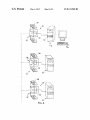
and become idle. As illustrated inn FIG. 3, the at least one
controller system 14 may instruct the ?rst switch 32 to move
from a connection with the ?rst leg 24 of the channel connec
ten via the associated chronological identi?ers, control acti
vation/deactivation of the at least one duplicator 3 6, and allow
the at least one host system 12 to freeZe a desired con?gura
tion until instructed not to do so. The freeZing of a desired
con?guration allows a user to copy the desired con?guration
tor 22 to a connection with the at least one duplicator 36.
from the host processing source storage system to any number
Similarly, the at least one controller system 14 may instruct
of available destination storage systems, thereafter allowing
the second switch 34 to move from a disconnected position to
a connection with the at least one duplicator 36. Once the
for duplication of the desired con?guration onto at least one
of the at least two storage systems. Such a process effectively
switching is complete, the at least one controller system 14
forces the at least one host system 12 to utiliZe an authoriZed
may instruct the at least one duplicator 36 to activate, at which
time the at least one duplicator 36 backs up a portion of or the
entire information contents of the source storage system 28 to
the at least one destination storage system 30. During this
process the communication path is one way, wherein the at
least one duplicator 36 reads from the source storage system
28 and writes to the at least one destination storage system 30.
desired con?guration located on a froZen backup destination
storage system regardless of any changes that take place
during the time it is being processed by the at least one host
system 12.
20
is a limited function read and write device. Accordingly, as
these systems are limited in function, their programming and
Once the backup process from the source storage system
28 to the at least one destination storage system 30 is com
plete, the at least one duplicator 36 may update and advise the
at least one controller system 14. As depicted in FIG. 4, the at
25
least one controller system 14 may then move the ?rst switch
32 to its ?rst position wherein the initial source storage sys
tem 28 is physically disconnected from the at least one dupli
cator 36 and is also physically disconnected from the ?rst leg
24 of the channel connector 22 and thus the at least one host
system 12. The initial source storage system 28 may then
assume the role of a destination storage system. The at least
30
35
channel connector 22 and thus to the at least one host system
12. The destination storage system 30 may then assume the
role of a host processing source storage system.
Thereafter, the at least one controller system 14 may return
the at least one host system 12 to its normal processing mode
and relinquish control of the ABR system 10. The at least one
host system 12 is now operating in normal fashion and may
now be processing from the initial destination storage system
30, which has now become the host processing source storage
system. The purpose for now running the at least one host
system 12 from the initial destination storage system 30 is to
assure that a proper backup process occurred from the initial
source storage system 28 to the initial destination storage
system 30. The initial source storage system 28 is now avail
able as a destination storage system should a negative event
befall the initial destination storage system 30 (now acting as
the source storage system) prior to the next backup process, at
whichpoint the at least one host system 12 may rapidly switch
back to processing from initial source storage system 28.
40
storage system is not thereby passed onto any of the at least
ner, either the at least one host system 12 is connected to and
may be processing from a source storage system or the ABR
system 10 is connected to and may be duplicating the source
storage system, but both the at least one host system 12 and
the ABR system 10 may not be simultaneously connected to
the same source storage system. The storage system may also
be con?gured in a state of disconnect from both the at least
one host system 12 and the ABR system 10.
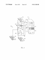
As depicted in another embodiment in FIG. 5, at least two
destination storage systems may be used within the ABR
system 10 of the present invention. In such con?gurations,
each additional destination storage system may have its own
switch which is capable of switching its respective storage
45
system to one of three positions: (1) a position of disconnect,
(2) a connection with an additional leg of the channel con
nector 22, or (3) a connection with the at least one duplicator
36. The at least one host system 12 may initially process from
50
55
During the next backup period, the backup process may be
the initial source storage system 28 (or any available storage
means) in the usual fashion, and as discussed above.
As further depicted in FIG. 5, the second switch 34 for the
?rst of at least two destination storage systems 30 may be in
a position of disconnect from both the second leg 26 of the
channel connector 22 and the at least one duplicator 36.
During a backup process, the at least one controller system 14
may instruct the at least two switching systems 18 to move a
third switch 35 to create a connection between the second of
at least two destination storage systems 31 and the at least one
reversed with the information contents of the initial destina
tion storage system 30, now communicating with the at least
one host system 12, being backed up onto the initial source
storage system 28. Once this backup process has completed,
control is also limited and can be isolated so that any malady
that affects the at least one host system 12 is not imparted onto
any of these systems. Additionally, when a destination stor
age system is physically disconnected from the at least one
host system 12, any corruption that is occasioned on the at
least one host system 12 and/or the host processing source
one disconnected destination storage systems. In such a man
one controller system 14 may also move the second switch 34
to its second position wherein the initial destination storage
system 30 is physically connected to the second leg 26 of the
As such, the at least two switching systems 18 are limited
function switching systems and the at least one duplicator 36
60
duplicator 36. The at least one controller system 14 may
additionally instruct the at least two switching systems 18 to
the initial source storage system 28 may once again be used as
move the ?rst switch 32 to create a connection between the
the host processing source storage system with the initial
destination storage system 30 again assuming the role of a
initial source storage system 28 and the at least one duplicator
backup destination storage system.
The at least one controller system 14 may manage time,
manage backup time intervals (e.g. automatically by the sys
tem 10, at regularly scheduled intervals, or upon user manual
65
36 (and thus inherently disconnecting the initial source stor
age system 28 from the at least one host system 12). The ?rst
of at least two destination storage systems 30 may remain in
a position of disconnect. In this manner, both the initial source
storage system 28 and the second of at least two destination