1
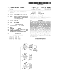
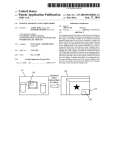
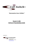
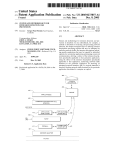
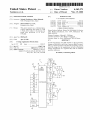
US006163271A
Ulllted States Patent [19]
[11] Patent Number:
Yoshizawa et al.
[45]
[54]
KEY-LESS ENTRY SYSTEM
[75]
Inventors: Takashi Yoshizawa; Akira Shimada,
Date of Patent:
[56]
References Cited
4,035,661
Assignee: Nissan Motor Co., Ltd.,
Kanagawwken, Japan
7/1977 Carlson ................................. .. 307/141
4,887,064 12/1989 Drori et a1
5,146,215 9/1992 Drori ..... ..
340/825.31
340/825.31
5,473,318
340/825.31
12/1995 Martel ....... ..
5,495,722
[*]
Notice:
*Dec. 19, 2000
U'S' PATENT DOCUMENTS
both of KanagaWa-ken, Japan
[73]
6,163,271
This patent issued on a continued prost'
l' t'
?l d
d 37 CFR
3213162131 25% 11221511336“ i0 $1: genty year
3/1996
Manson et a1. ......................... .. 236/51
OTHER PUBLICATIONS
Nissan Product Bulletin: Nissan 240 SX Model S14 Series;
patent term provisions of 35 USC'
1995 Model Introductron; Feb. 1994, Pubhcatlon No.
154(21)(2)_
PB5E—0S14U0.
Primary Examiner—HoWard L. Williams
[21] APPL NO; 09/056,615
[22] Filed:
[30]
Assistant Examiner—Jean Bruner Jeanglaude
Attorney, Agent, or Firm—McDermott, Will & Emery
[5 7]
ABSTRACT
An ID setup/change unit (61) adapted for ID registration,
Apr. 8, 1998
Forelgn Apphcatlon Prmnty Data
Apr. 8, 1997
[JP]
Japan .................................. .. 9-089672
7
change and deletion to and from a memory (46) is connect
able to a vehicle-mounted controller (3), permitting a facili
[51]
Int. Cl.
...................................................... .. G06F 7/04
52
U S C]
340 825 31_ 340 825 34
tated ID storage for the registration, as Well as faclhtated
240/825’ 31 gzs '34
change and deletion of a registered ID, With an enhanced
%58} F: I'd
1e
"""
0
earc
....................... ..
.
,
.
,
340/825.72, 825.69, 825.32; 307/101, 10.2,
10.3, 10.7, 10.9, 141, 364/150
CONTROLLER
TEST
61
.
.
Operation ef?ciency~
20 Claims, 13 Drawing Sheets
. .
U.S. Patent
Dec. 19,2000
Sheet 1 0f 13
6,163,271
FIG. 1
23
2
i7 21
/
BAT
1a\
1b
‘
\/
CONTROLLER
22
/
EEPROM
U.S. Patent
Dec. 19,2000
Sheet 2 0f 13
6,163,271
FIG. 3
3
/3
T
I>——O
O—0
m1 .50-,
I3.
0
l
BAT
4;
‘3130
CONTROLLER
32
i151?II!Mg‘
EEPROM
TEST
V
U.S. Patent
Dec. 19,2000
Sheet 3 0f 13
6,163,271
FIG. 4
S1
A SYSTEM SELECTION
\A
III
FOR DIAGNOSIS
|
T
ENGINE
AT
|
I
l
SMART ENTRANCE
|
A PART SELECTION
S20
FOR DIAGNOSIS
I
I
L_
U
DOOR LOCK
KEY-LESS ENTRY
|
l
ALARM FOR KEY
LEFT INSERTED
REMOTE CONTROL
ID SETTING
I
A REMOTE CONTROL ID
S3 \A
SETUP/CHANGE SELECTION
REMOTE CONTROL ID
MEMORY CHECK
REMOTE CONTROL ID
REGISTRATION
REMOTE CONTROL ID
DELETION
5
U.S. Patent
Dec. 19, 2000
Sheet 4 0f 13
6,163,271
FIG. 5
s4“
REMOTE CONTROL ID
MEMORY CHECK
S5
V
O REMOTE CONTROL ID CHECK.
PUSH BUTTON ON
REMOTE CONTROLLER,
CHECKING NUMBER OF MEMORY
WITH REGISTERED ID-
MEMORY-l
MEMORY‘Z
MEMORY-3
MEMORY-4
BACK
MEMORY NUMBER IS HIGHLIGHTED
FOR 156C, WHEN ID OUTPUT
FROM REMOTE CONTROLLER
IS IN ACCORD WITH ID IN RECEIVER.
NO RESPONSE TO OCCUR, EVEN IF
MEMORY NUMBER IS PRESSED.
U.S. Patent
Dec. 19,2000
Sheet 5 0f 13
6,163,271
FIG. 6
S6
[REMOTE CONTROL ID REGISTRATIONI
IN OTHER CASE
S7
[FOR SINGLE REGISTERED 111
‘5
A '
0 REMOTE CONTROL ID 0
HIGHLIGHTED OF
REMOTE
CONTROL ID
CAN BE REGISTERED.
REOISTESIED
(IFS
WHEN
E P
SELECT NUMBER OP
MEMORY FOR DESIRED
REGISTRATION.
MEMORY-1 TO
MEMORY-4 IS
OPERATED AS A KEY
I
FOR SELECTION.
,
AUTOMATICALLY
IE SELECTED
NUMBER IS
OF MEMORY
RERgg ID
_
C
NUMBERS ARE
ELSE FLOW
MEMORY 1
I MEMORY-3
[ MEMORY-4 | GOES AS SHOWN‘
WHEN SELECTED NUMBER IS OF
38“
MEMORY WITH REGISTERED ID
0
0
THIS MEMORY HAS
REGISTERED ID
WILL YOU CHANGE '2
YES
NO
>4
I
r\
\
B
.
59\,\
I
NUMBER IS HIGHLIGHTED
0 REMOTE CONTROL ID 0
OF MEMORY
WITH REGISTERED ID.
REGISTRATION
REMOTE CONTROL ID
CAN BE REGISTERED.
SELECT NUMBER OF MEMORY
THE FLOW GOES As SHOWN.
Fgghlzgglég‘?lgq'
NO RESPONSE WILL OCCUR,
NOT REGISTER
"NH/H,
Q,P/M9B¥'1%
MEMORYQ
.
MEMORY-3
FOR SELECTION,
WHEN SELECTED
'
/
WHEN ONE OF MEMORY-1
TO MEMORY-4
IS OPERATED AS A KEY
NUMBER IS OF MEMORY
WITH REGISTERED ID.
X DENOTES
NUMBER OF MEMORY
MEMORY-4
WITH REGISTERED ID.
WHEN NUMBER IS SELECTED OF
NON—REGISTERED MEMORY
U.S. Patent
Dec. 19, 2000
Sheet 6 0f 13
6,163,271
FIG. 7
310“
Q REMOTE CONTROL ID .
REGISTRATION
PRESS BUI ION ON REMOTE
CONTROLLER.
ID WILL BE REGISTERED.
I
0 REMOTE CONTROL ID 0
REGISTRATION
NO RESPONSE TO OCCUR,
EVEN IF MEMORY NUMBER
IS PRESSED.
REGISTERED.
/
///////////
@WMQBbM/A
//////////
END
END
/
MEMORY-4
NEXT
REGISTRATION
NEXT
REGISTRATION
U.S. Patent
Dec. 19, 2000
Sheet 7 0f 13
6,163,271
FIG.
S12\,\ REMOTE CONTROL ID
DELETION
(
Sl3\,\
,
Q REMOTE CONTROL ID Q
NO RESPONSE TO OCCUR,
UPON SELECTION OF
NON-REGISTERED
MEMORY NUMBER.
NUMBER IS HIGHLIGHTED OF
DELETION
SELECT NUMBER OF MEMORY
FOR DESIRED DELHI‘ ION.
/
//////////
%MEM9BY~1%
MEMORY-2
MEMORY-3
MEMORY-4
MEMORY WITH REGISTERED ID.
ALL MEMORY
DELETION
FOR SELECTION OF
HIGHLIGHTED MEMORY
NUMBER OR ALL MEMORY
DELETION
S14\N
,
0 REMOTE CONTROL ID 6
DELETION
NUMBER IS NORMALLY
DISPLAYED OF MEMORY
WITH DELETED ID.
DELETED.
MEMORY-1
MEMORY-2
MEMORY-3
MEMORY-4
NEXT
DELETION
END
END
NO RESPONSE TO OCCUR,
EvEN IF MEMORY NUMBER
IS PRESSED.
NEXT
DELETION
U.S. Patent
Dec. 19,2000
Sheet 8 0f 13
6,163,271
FIG. 9
S1
A SYSTEM SELECTION
m
II]
FOR DIAGNOSIS
ENGINE
AT
SMART ENTRANCE
A PART SELECTION
82$
FOR DIAGNOSIS
l
|
DOOR LOCK
KEY-LESS ENTRY
ALARM FOR KEY
LEFT INSERTED
REMOTE CONTROL
ID SETTING
V
A REMOTE CONTROL ID
S30
SETUP/CHANGE SELECTION
REMOTE CONTROL ID
MEMORY CHECK
REMOTE CONTROL ID
REGISTRATION
REMOTE CONTROL ID
DELETION
El
|
I
6,163,271
1
2
KEY-LESS ENTRY SYSTEM
for executing trouble diagnoses of diverse vehicle-mounted
control systems.
BACKGROUND OF THE INVENTION
According to a third aspect of the invention, the ID setup
and change unit displays an address in the memory Where an
ID of the remote controller is stored.
According to a fourth aspect of the invention, the ID setup
and change unit is adaptive for storing an ID of the remote
controller at an arbitrary address in the memory.
According to a fourth aspect of the invention, the ID setup
and change unit is adaptive for deleting an ID stored at an
1. Field of the Invention
The present invention relates to a key-less entry system
for remote-control operations, such as vehicle door lock/
unlock operations to be performed by ID (identi?cation
number) collation Without employing an ignition key, and
particularly, it relates to a key-less entry system improved of
ID registration.
10
arbitrary address in the memory.
Further, to achieve the object described, a siXth aspect of
the invention provides a key-less entry system for vehicles,
2. Description of Relevant Art
There are key-less entry systems put to practical use. They
are of a type in Which an ID is collated to effect remote
comprising a ?rst controller ?Xed to a vehicle, the ?rst
control of a door to be locked or unlocked, as Well as of a 15 controller being operative for collating an input ID thereto
trunk lid to be opened, Without inserting a key into a key
With one or more registered ID’s stored therein and respon
cylinder and operating the inserted key to be rotated.
sive to a match therebetWeen to alloW key-less entry into the
vehicle, a second controller operative at a remote distance
from the vehicle to transmit a preset ID to be received by the
Such systems have a key-less remote controller
(hereinbeloW “remote controller”) provided With a door lock
?rst controller, as the input ID thereto, and a third controller
connectable to the ?rst controller and operative in a selective
one of a ?rst mode for processing the input ID to store the
input ID as a registered ID in the ?rst controller and a second
sWitch, a door unlock sWitch and a trunk opener sWitch.
When any sWitch is operated, its operation data are trans
mitted from the remote controller together With an oWn ID
of the remote controller. The transmitted data and ID are
received by a key-less entry controller at a vehicle end
(hereinbeloW “vehicle-mounted controller”), Where the
mode for processing to delete at least one of the one or more
25
transmitted ID is collated With a registered ID and, if they
registered ID’s.
match, the transmitted data are processed to eXecute a
According to a seventh aspect of the invention, the ?rst
controller has a plurality of memory locations including one
process corresponding to the operated sWitch, i.e., a door
or more memory locations for storing therein the one or
locking or unlocking process or a trunk opening process.
more registered ID’s in a one-to-one corresponding manner,
and the third controller is operative in the ?rst mode for
The vehicle-mounted controller is adapted for registration
of a predetermined number of ID’s, by the provision of
sWitches connected thereto, Which sWitches are operable in
changing one of the one or more registered ID’s stored in
one of the one or more memory locations, to the registered
an instructed manner to enter an ID registration mode. In
ID.
conventional key-less entry systems, the registration of a
neW ID is permitted (1) after deletion of all ID’s that have
been registered or (2) after deletion of one of registered ID’s
that is earliest of registration.
According to an eighth aspect of the invention, the third
35
controller is operative for indicating an address of a respec
tive one of the one or more memory locations.
According to a ninth aspect of the invention, the third
The case (1) needs all the registered ID’s to be once
deleted before a reneWed registration of ID’s to be
controller prevents the input ID from being processed to be
registered, With registration of the neW ID inclusive, and is
locations.
According to a tenth aspect of the invention, the third
controller is operative in the second mode to enter a selective
stored as the registered ID in one of the one or more memory
unfavorable in efficiency of operation.
The case (2) also has unfavorable operation ef?ciency in
the event of a missing remote controller needing all regis
tered ID’s to be once deleted by repeating registration of a
respective one of neW ID’s as many times as their number.
one of a third mode for deleting a selective one of the one
45
SUMMARY OF THE INVENTION
panel display operative for entering a coded data.
Therefore, according to the ?rst aspect, there is permitted
a facilitated ID storage, change and deletion simply by
The present invention has been achieved With such points
in vieW.
It therefore is an object of the present invention to provide
a key-less entry system facilitated in neW registration,
change and deletion of ID’s.
To achieve the object, a ?rst aspect of the invention
provides a key-less entry system comprising a remote con
troller for transmitting an ID When an operation element is
operated, and a vehicle-mounted controller for receiving the
ID transmitted from the remote controller, collating the ID
With an ID stored as a registered ID in a memory, and
responding to a match therebetWeen for execution of a
corresponding process to the operation element, Wherein at
ID setup and change unit for performing a storage of an ID
or more registered ID’s and a fourth mode for deleting all of
the one or more registered ID’s by a single operation.
According to an eleventh aspect of the invention, the third
controller comprises a data processor provided With a touch
55
connection of an ID setup and change unit to a vehicle
mounted controller.
According to the second aspect, a trouble diagnostic
device is commonly employed as an ID setup and change
unit that otherWise might have been provided for a dedicated
purpose.
According to the third aspect, a possible checkup of ID
registration facilitates ?nding a troubling point, as Well as a
memory address check before ID deletion.
According to the fourth aspect, re-registration of an
eXisting ID is unnecessary When registering an additional
ID.
According to the ?fth aspect, a missing remote controller
to be registered and a change and a deletion of a registered
ID relative to the memory is connectable to the vehicle
mounted controller.
65 Will not require deleting other ID’s than its ID.
According to the siXth aspect, an operator can select one
According to a second aspect of the invention, the ID
of ?rst and second modes in a voluntary manner.
setup and change unit comprises a trouble diagnostic device
6,163,271
4
3
According to the seventh aspect, possible registration of
The remote controller 2 is constituted With a controller 21
as a principal component including a microcomputer. The
a neW ID ensures an enhanced operation efficiency.
controller 21 is connected to or interfaced With a non
According to the eighth aspect, a prompt visible con?r
mation is possible to check for an unused memory location.
volatile memory 22, such as an EEPROM (electrically
According to the ninth aspect, there is effected a potential
prevention of a mistaken or unlaWful ID change.
According to the tenth aspect, possible deletion of an
individual ID alloWs an intentional deletion, and that of
ID stored therein for the individual key, the door lock sWitch
1a, the door unlock sWitch 1b, an antenna 23, and a battery
erasable programmable read only memory), With the proper
BAT.
The vehicle-mounted controller 3 is constituted With a
controller 31 as a principal component, as in FIG. 3. The
Whole ID’s assures a saved time.
According to the eleventh aspect, there can be achieved a
controller 31 comprises a microcomputer With peripheral
compact and inexpensive controller.
BRIEF DESCRIPTION OF THE
ACCOMPANYING DRAWINGS
15
The above and further objects and novel features of the
present invention Will more fully appear from the folloWing
detailed description When the same is read in conjunction
devices and a tuner 31a, and is adapted for lock/unlock
control of respective doors aside a driver’s seat, an assis
tant’s seat and left and right rear passenger’s seat of the
automobile, Which doors have their door lock actuators 32 to
35. The tuner 31a reproduces the transmitted data from the
remote controller 2. The door lock actuators 32 to 35 are
each respectively controllable to drive an unshoWn door lock
mechanism of a corresponding door into one of its lock and
With the accompanying draWings, in Which:
FIG. 1 is a perspective vieW of an ignition key including
unlock positions.
a remote controller of a key-less entry system according to
an embodiment of the invention;
FIG. 2 is a circuit diagram of the remote controller of FIG.
One door provided at the driver’s seat is associated With
the door lock actuator 32, Which is controlled by a combi
nation of a lock relay 36 and an unlock relay 38. The lock
relay 36 is drivable With a transistor 37 for supplying electric
1;
FIG. 3 is a circuit diagram of a vehicle-mounted controller 25 poWer from a battery BAT to a terminal of the door lock
actuator 32 to drive the door lock mechanism of the door at
FIGS. 4 to 8 are ?oWcharts of actions of the key-less entry
the driver’s seat into its lock position. An output line from
system, respectively; and
the lock relay 36 to the door lock actuator 32 is connected
to the controller 31, for monitoring a locking output thereon.
FIGS. 9 to 14 are ?oWcharts of actions of a key-less entry
The unlock relay 38 is drivable With a transistor 39 for
system according to another embodiment of the invention,
supplying electric poWer from the battery BAT to an oppo
respectively.
site terminal of the door lock actuator 32 to drive the door
DETAILED DESCRIPTION OF THE
lock mechanism of the door at the driver’s seat into its
PREFERRED EMBODIMENTS
unlock position. An output line from the unlock relay 38 to
35
the door lock actuator 32 is also connected to the controller
There Will be detailed beloW the preferred embodiments
of the key-less entry system;
31, for monitoring an unlocking output thereon.
of the present invention With reference to the accompanying
draWings. Like members are designated by like reference
characters.
FIG. 1 illustrates an appearance of an ignition key having
an incorporated key-less remote controller (hereafter some
times “remote controller”) of a key-less entry system
The remaining doors provided at the assistant’s seat and
the left and right rear passenger’s seats are associated With
the door lock actuators 33—35, Which are commonly con
trolled by a combination of a lock relay 41 and an unlock
relay 43. The lock relay 41 is drivable With a transistor 42
for supplying electric poWer from the battery BAT to ter
according to a ?rst embodiment of the invention, as it is
applied to an unshoWn automobile of Which an engine starter
and respective doors and trunk lids are operable by the
ignition key, and FIGS. 2 and 3 shoW circuit diagrams of the
45
minals of the door lock actuators 33—35 to drive the respec
tive door lock mechanisms of the doors at the assistant’s and
the automobile (hereafter sometimes “vehicle-mounted
left and right rear passenger’s seats into their lock positions.
A common output line from the lock relay 36 to the door
lock actuators 33—35 is connected to the controller 31, for
controller”) of the system, respectively.
monitoring a locking output thereon. The unlock relay 43 is
In the ?gures, designated by reference numeral 1 is the
ignition key, 2 is an entirety of the remote controller and 3
is that of the vehicle-mounted controller. The key-less entry
system according to the present embodiment comprises the
drivable With a transistor 44 for supplying electric poWer
from the battery BAT to opposite terminals of the door lock
remote controller and a key-less entry controller installed in
remote controller 2 (FIG. 2) incorporated in the key 1 (FIG.
1), and the vehicle-mounted controller 3 (FIG. 3). The
incorporated remote controller 2 in the key 1 may be
separated therefrom as an individual unit.
The remote controller 2 of FIG. 2 is buried or housed in
the key 1. As illustrated in FIG. 1, the key 1 has a grip as a
head, Where it has a door lock sWitch 1a and a door unlock
sWitch 1b eXposed outside as operable elements at the
remote controller end. The remote controller 2 responds to
an operation of the door lock sWitch 1a to transmit a set of
data on locking information and a preset proper ID
(identi?cation number) of the key 1, and to an operation of
55
actuators 33—35 to drive the door lock mechanisms of the
doors at the assistant’s and left and right rear passenger’s
seats into their unlock positions. Acommon output line from
the unlock relay 43 to the door lock actuators 33—35 is also
connected to the controller 31, for monitoring an unlocking
output thereon.
The controller 31 is further connected to or interfaced
With an antenna 45, and a non-volatile memory 46 such as
an EEPROM. The antenna 45 is arranged in a rear Wind
shield of the automobile, for receiving electromagnetic
Waves transmitted from the remote controller 2 in a Wireless
manner.
A storage region of the memory 46 has four numbered
65 memory locations addressed as address-1 to address-4
the door unlock sWitch 1b to transmit a set of data on
(hereafter sometimes “memory-1” to “memory-4” in terms
unlocking information and the ID of the key 1.
of memory location number) and secured for storing at most
6,163,271
5
6
four ID’s of the remote controller 2. The non-volatile
memory 46 may be other than EEPROM. The number of
memory locations or addresses secured for ID storage may
be a voluntary, other than four.
The controller 31 is further connected to various indicator
ing ID is highlighted for an interval of one second.
Thereafter, the How again goes to the step S3 of FIG. 4,
displaying the remote control ID setup/change selection
screen.
The remote control ID setup/change selection screen
further has a “remote control ID registration” mode. If this
mode is selected, the How goes to a step S6 shoWn in FIG.
sWitches including a driver’s seat door key cylinder lock
sWitch 47 to be close When a key cylinder of the door at the
6. The remote control ID registration mode is for processing
driver’s seat is in its lock position, an assistant’s seat door
key cylinder lock sWitch 48 to be close When a key cylinder
of the door at the assistant’s seat is in its lock position, four
door sWitches 49—52 to be each individually close When a
corresponding one of the doors at the driver’s seat, the
assistant’s seat and the left and right rear passenger’s seat is
detected to be open, a key sWitch 53 to be close When the
10
ignition key 1 is inserted into a key cylinder therefor, and an
accessory sWitch 54 to be close When the ignition key 1 is
15
a transmitted ID from the remote, controller 2 to register it
at a selective one of the four memory addresses, i.e., to store
it at a corresponding memory location in the memory 46,
Whereas for the memory location selection a corresponding
address key is to be operated by pressing. At the step S6, if
the memory 46 has a single ID stored therein, then the How
goes to a step S9. In other cases, i.e., When the memory 46
has tWo or more ID’s or no ID stored therein, the How goes
to a step S7, Where it displays a remote control ID registra
set to an ACC (accessory) position.
For the vehicle-mounted controller 3 is provided a trouble
tion screen, highlighting respective address keys of memory
diagnostic device 61 of a portable type for diagnosing
locations in Which certain ID’s are stored. In exemplary
illustration of the step S7 in FIG. 6, tWo ID’s are already
failures, faults, malfunctions and other troubles such as of an
engine control system, an automatic transmission device and
stored at a memory-1 and a memory-2 in a one-to-one
the key-less entry system. The diagnostic device 61 is
are highlighted. When an address key is operated at the step
S7, if an ID is registered at a corresponding memory address,
then the How goes to a step S8, giving a message for
corresponding manner, and tWo corresponding address keys
adapted for connection to the controller 31 to effect a neW
registration, change and deletion of ID’s relative to the
key-less entry system. To this point, the diagnostic device 61
has a display With touch key sWitches operable for data entry
con?rmation as to Whether or not the registered ID should be
changed. When a response thereto is made by operating a
“YES” key, the How goes (via a node B) to a step S10 shoWn
and display. The trouble diagnostic device 61 may be a
separate type composed of a stationary unit dedicated for
trouble diagnoses of vehicle-mounted objects such as the
engine control system and the automatic transmission
device, and a portable unit dedicated for setup and change of
in FIG. 7 for changing the registered ID to a neW ID. If a
“NO” key is operated, the How again goes to the step S7. If
a memory location corresponding to the address key oper
ated at the step S7 has no ID stored therein, the How directly
ID’s.
There Will be described actions of the key-less entry
system according to the present embodiment, With reference
to FIGS. 4 to 8.
The trouble diagnostic device 61 is noW connected to a
dedicated port of the vehicle-mounted controller 3, and an
unshoWn main sWitch is turned on, alloWing for a trouble
diagnostic process to start. First, at a step S1 of FIG. 4, the
display of the diagnostic device 61 displays a screen of a
trouble diagnosis menu for selection of a target system to be
diagnosed. A smart entrance system is noW selected, as it is
a nomenclature of the key-less entry system in concern.
Then, a programmed control How of the process goes to a
step S2, Where it displays a screen for selection of items to
be diagnosed in the entrance system. A “remote control ID
goes to the step S10 to register a neW ID in the unused
memory location.
35
In the case a single ID is registered at the step S6, the How
goes to the step S9 to display a screen for having one of the
four memory addresses selected for registration of a neW ID.
The single ID is stored by using a certain memory location
and a corresponding address key may be operated for the
selection, Which select operation hoWever is ineffective and
Will not be accepted, i.e., the How stays at the step S9. When
an address key of an unused memory location is operated,
the How goes to the step S10.
At the step S10, there are displayed messages instructing
45
a necessary operation to register a neW ID. With this
operation performed, an ID is received as the neW ID from
the remote controller 2 and stored in a memory location
setup/change” is noW eXemplarily selected, and the control
designated by an operation at the step S7 or S9. Then, a
How goes to a subsequent step S3, Where it displays a screen
With a header of remote control ID setup/change selection.
The remote control ID setup/change selection screen has
a “remote control ID memory check” mode. If this mode is
selected, the How goes to a step S4 shoWn in FIG. 5. The
remote control ID memory check mode is for a check
subsequent step S11 displays a message of completion of
remote control ID registration, highlighting address keys of
memory locations having registered ID’s. An “END” key is
operable to go to the step S3, Where the remote control ID
setup/change selection screen Will be displayed. If a “next
registration” key is operated, the How again goes to the step
Whether or not a transmitted ID from the remote controller 55 S7, permitting another neW ID to be registered in the
2 is registered, i.e., if a matching ID is stored in the memory
46. According, at a step S5, there is displayed a remote
described manner. The ID registration may be effected at the
step S10 in an overWriting manner, Without deletion of an
control ID check screen With a message instructing an
eXisting ID, e.g., by bypassing the step S8 or steps S7 to S9.
operation of the remote controller 2. Upon this operation, an
The remote control ID setup/change selection screen has
a key for a “remote control ID deletion” mode. When this
ID is transmitted from the remote controller 2 and received
at the vehicle-mounted controller 3, Where it is collated With
one or more ID’s read from the memory 46. When the
received ID matches a read ID, i.e., if a matching ID is stored
at one of the four addressed memory locations in the
memory 46, then one of four address keys (displayed With
indications of “memory-1” to “memory-4” on the screen)
that corresponds to an address of the location of the match
65
key is operated, the How goes to a step S12 shoWn in FIG.
8. The remote control ID deletion mode permits ID’s reg
istered at all memory addresses of the storage region of the
memory 46 to be Wholly deleted, as Well as an ID registered
at any memory address to be deleted. To this point, a step
S13 displays a screen including an “all memory deletion”
key and four address keys. The four address keys are each
6,163,271
7
8
operative to select a memory address of an ID to be deleted.
highlighted and have ID’s registered at their addresses.
Any address key having a registered ID at a corresponding
memory address is highlighted. An address key of an unused
memory location may be operated for selection, Which
operation hoWever is ineffective and Will not be accepted.
When an address key of an unused memory location or of an
address having no registered ID is operated, i.e., When a
non-highlighted address key is pressed, the How goes to a
step S27. If the address key of any address that has a
Upon operation to the “all memory deletion” key or to an
registered ID is operated, i.e., if any highlighted address key
address key of any memory address having a registered ID,
is pressed, the How goes to a step S28.
In the case the address key having no ID registered at its
the How goes to a step S14, Where in the latter case the
registered ID is deleted from the address of the selected
address key. In the former case, i.e., in the case the “all
memory deletion” key is operated, all ID’s stored at the
memory address is selected, there is displayed at the step
10
S27 a screen indicating the selected address or memory
15
message for operation of the remote controller 2. When a
transmitted ID from the remote controller 2 is stored in a
selected memory location, the How goes (via a node E) to a
step S29 shoWn in FIG. 12, Where it gives a message of
location number (eg “memory-2”), With an instruction
addresses-1 to -4 are Wholly deleted. In either case, the
address key of each memory address having deleted ID is
normally displayed, i.e., not highlighted yet. An “END” key
is operable to go to the step S3, Where the remote control ID
setup/change selection screen Will be displayed. If a “next
completion of ID registration, highlighting a respective
deletion” key is operated, the How again goes to the step
S13, permitting another registered ID to be deleted from an
address key that has an ID registered at its address. If a time
interval exceeding 30 seconds has elapsed With no ID
associated memory address in the described manner.
transmitted from the remote controller 2 or When a received
There Will be described beloW a key-less entry system
according to a second embodiment of the invention that has
an analogous constitution to the key-less entry system
according to the ?rst embodiment shoWn in FIGS. 1 to 3.
The description Will thus be made of actions in the second
embodiment, With reference to FIGS. 9 to 14.
At steps S1 to S3 shoWn in FIG. 9, programmed actions
ID is unsuccessfully registered or unable to be registered for
a reason the ID is to be blamed, the How goes to a step S30,
Where it indicates a registration error message. When the
vehicle-mounted controller 3 has failed to achieve a suc
cessful ID registration for a reason it has the responsibility,
25 such as for a functional error in registration, the How goes
to a step S31 to give a message Warning an abnormal
registration function as a probable cause.
in the second embodiment are similar to those in the ?rst
embodiment shoWn in FIG. 4.
In a remote control ID setup/change selection screen of
FIG. 9, if a “remote control ID memory check” mode is
selected, a program How goes to a step S21 shoWn in FIG.
10. The remote control ID memory check mode is for a
check Whether or not a transmitted ID from a remote
controller 2 is registered. At a step S22, there is displayed a
35
If the address key operated at the step S26 has an ID
registered at its address, the How goes to the step S28, as
described, and indicates a Warning message of presence of
a registered ID at the selected address, suggesting a deletion
of the registered ID to be executed before a desired regis
tration. If an “END” key is then operated, the How again
goes to the step 3 to display the remote control ID setup/
change selection screen. The ID registration in the second
remote control ID check screen With a message instructing
embodiment may be effected at the step S27 in an overWrit
an operation of the remote controller 2. Upon this operation,
ing manner, Without deletion of an existing ID, e.g., by
an ID is transmitted from the remote controller 2 and is
received at a vehicle-mounted controller 3, Where it is
collated With registered ID’s, as they are read from a
memory 46. When the received ID matches a registered ID,
i.e., if a matching ID is stored in an addressed memory
location of the memory 46, then at a step S23 an address key
that corresponds to an address of the memory location of the
matching ID is highlighted. If a number of ID’s read from
a number of memory locations are matching With the
omitting the step S28.
The remote control ID setup/change selection screen of
FIG. 9 also has a key for a “remote control ID deletion”
mode. When this key is operated, the How goes to a step S32
shoWn in FIG. 13. The remote control ID deletion mode
permits ID’s registered at all memory addresses of the
storage region of the memory 46 to be Wholly deleted, as
45
deleted. The step S32 displays a screen including an “all
received ID, i.e., if they are each respectively identical to the
received ID, there are highlighted a corresponding number
of address keys. Thereafter, the How again goes to the step
S3 of FIG. 9, displaying the remote control ID setup/change
memory deletion” key and four address keys, With an
instruction message for address key operation. The four
address keys are each operative to select a memory address
of a registered ID to be deleted. Each address key having a
registered ID at a corresponding address is highlighted. The
“all memory deletion” key is operative to delete Whole ID’s
selection screen. If the received ID is not registered at any
address at the step S22, the How goes therefrom to a step S24
for displaying a message “non-registered”.
The remote control ID setup/change selection screen of
FIG. 9 further has a “remote control ID registration” mode.
If this mode is selected, the How goes to a step S25 shoWn
in FIG. 11. The remote control ID registration mode is for
processing a transmitted ID from the remote controller 2 to
register it at a selective one of four memory addresses, so
that it is stored in a corresponding addressed memory
location of a storage region of the memory 46. At a step S26,
there is displayed a remote control ID registration screen,
Which is highlighted at an address key of each memory
address having a registered ID and Which gives a message
instructing an operation of an address key of any address for
a desired ID registration. In exemplary illustration in FIG.
11, address keys of a memory-1 and a memory-3 are
Well as an ID registered at any memory address to be
stored in all memory locations. Upon key operation to any
of those keys, the How goes to a subsequent step S33, Where
55 it indicates a message demanding an instruction for a
decision as to Whether or not the registered ID(s) at the
selected (or all) address(es) should be deleted. If a “NO” key
is then operated, the How again goes to the step S32 to
display a remote control ID deletion screen.
When a “YES” key is operated to consent to the decision
for ID deletion at the step S33, the How goes (via a node F)
to a step S34 shoWn in FIG. 14, Where it deletes (a)
registered ID(s) at the selected (or all) address(es), display
ing the ID(s) to be deleted. Upon completion of the ID
65
deletion, the How goes to a step S35 to display a screen With
a message of complete deletion and four address keys. For
any memory address Where a registered ID has been deleted,
6,163,271
9
10
a corresponding address key is not highlighted yet. When the
a second controller ?xed to the vehicle, the second
vehicle-mounted controller 3 has failed to achieve a suc
cessful ID deletion at the step S34 for a reason it has the
responsibility, such as for a functional error in deletion, the
How goes to a step S36 to give a message Warning an
abnormal deletion function as a probable cause.
controller having a plurality of memory locations for
individually storing a plurality of registered IDs, the
second controller receiving the ID transmitted from the
?rst controller as an input ID, the second controller
being operative for collating the input ID With a reg
istered ID in any of the plurality of memory locations
In the embodiments described, key-less remote controller
2, the memory 46, the vehicle-mounted key-less entry
and responsive to a match therebetWeen to disarm
controller 3 and the trouble diagnostic device 61 may
individually comprise a remote controller as an ignition key,
key-less entry into the vehicle;
10
and
a third controller selectively connectable to the second
controller and operative for visual identi?cation and
manual selection of any of the plurality of memory
15
of a ?rst mode for registering the input ID in a manually
a memory of an incorporated disc or external connection
type, a vehicle-mounted controller of a stationary or partially
mobile arrangement, and an ID setup/change unit comprised
of a data processor provided With a touch panel type display
operative for entry of various data such as coded data.
Respective touch keys such as address keys displayed on
locations and to indicate to prompt a user to select one
an associated screen may be individually provided as opera
selected one of the plurality of memory locations and a
second mode for deleting a registered ID from a
tional key sWitches on a housing of the display.
While preferred embodiments of the present invention
manually selected one of the plurality of memory
locations.
have been described using speci?c terms, such description is
7. The key-less entry system for vehicles according to
claim 6, Wherein the third controller is operative for indi
cating an occupied condition of the manually selected one of
the plurality of memory locations.
8. The key-less entry system for vehicles according to
claim 6, Wherein the third controller prevents the input ID
from being stored in an occupied one of the plurality of
for illustrative purposes, and it is to be understood that
changes and variations may be made Without departing from
the spirit or scope of the folloWing claims.
What is claimed is:
1. A key-less entry system comprising:
25
a memory having a plurality of memory locations for
memory locations.
individually storing a plurality of registered IDs;
9. The key-less entry system for vehicles according to
claim 6, Wherein the third controller is operative in the
second mode to effect selecting one of deleting a single
a remote controller for transmitting an ID When an
operation element is operated;
a vehicle-mounted controller for receiving the ID trans
registered ID and deleting all registered ID’s by a single
mitted from the remote controller, collating the ID With
a registered ID in any of the plurality of memory
operation.
10. The key-less entry system for vehicles according to
locations and responding to a match therebetWeen for
executing a corresponding process to the operation
35
element; and
visually identi?able keys operative for said manual selec
an ID setup and change unit operative for visual identi
?cation and manual selection of any of the plurality of
tion.
11. The key-less entry system for vehicle according to
memory locations and to prompt a user as to a manual
claim 6, Wherein the third controller includes a touch panel
operation of the ID setup and change unit for registra
display to prompt a user to select either one of the ?rst and
tion of the received ID in a manually selected one of the
plurality of memory locations and for deletion of a
registered ID from a manually selected one of the
plurality of memory locations and responsive to said
manual operation to select one of said registration and
second modes.
12. The key-less entry system for vehicles according to
claim 6, Wherein the third controller is portable, and the
45
said deletion.
Wherein the third controller is further operative, response to
Wherein the ID setup and change unit comprises a trouble
diagnostic device separate from the vehicle-mounted con
troller and manually connectable thereto for executing
trouble diagnoses of diverse vehicle-mounted control sys
the user’s manual operation thereto, to perform diagnosis on
an engine and an automatic transmission system.
14. A key-less entry system for vehicles in Which an
originated ID is authenticated relative to a registered ID to
tems.
disarm key-less entry to a vehicle, the system comprising:
a plurality of registration locations to be individually
3. The key-less entry system according to claim 1,
Wherein the ID setup and change unit displays a matching
condition betWeen the received ID and a registered ID in a 55
manually selected one of the plurality of memory locations.
4. The key-less entry system according to claim 1,
Wherein the ID setup and change unit displays an occupied
5. The key-less entry system according to claim 1,
Wherein the ID setup and change unit displays a vacant
condition of a manually selected one of the plurality of
memory locations.
vehicle to transmit a present ID;
occupied With an ID to be registered;
an ID originator for originating an ID;
an ID authenticator for receiving the originated ID and for
authenticating the received ID relative to a registered
ID; and
a controller for controlling occupation of the plurality of
registration locations to be visualiZed in an individually
identi?able manner, the controller being responsive to
condition of a manually selected one of the plurality of
memory locations.
6. A key-less entry system for vehicles, comprising:
second controller has a dedicated part for connection to the
third controller.
13. The key-less entry system according to claim 6,
2. The key-less entry system according to claim 1,
a ?rst controller operative at a remote distance from a
claim 6, Wherein the third controller includes a touch panel
display for displaying the plurality of memory locations as
a manual operation thereto for a random access to an
65
arbitrary registration location to change an occupied
state of the arbitrary registration location.
15. The key-less entry system for vehicles according to
claim 14, Wherein the controller is responsive to the manual
6,163,271
11
12
operation to register the received ID in the arbitrary regis
a third controller selectively connectable to the ?rst
tration location.
controller and operative to prompt a user to select one
16. The key-less entry system for vehicles according to
claim 14, Wherein the controller is responsive to the manual
operation to delete a registered ID from the arbitrary regis
controller as another registered ID and a second mode
of a ?rst mode for registering the input ID in the ?rst
for arbitrarily selecting at least one of all registered
ID’s in the ?rst controller and deleting the selected at
least one of all registered ID’s, Wherein
the ?rst controller has a plurality of memory locations
tration location.
17. The key-less entry system for vehicles according to
claim 14, Wherein the controller includes a touch panel
display for displaying the plurality of registration locations
as visually identi?able keys each respectively operative by
the manual operation.
18. A key-less entry system for vehicles in Which an
originated ID is authenticated relative to a registered ID to
disarm key-less entry to a vehicle, the system comprising:
a plurality of registration locations to be individually
occupied With an ID to be registered;
originating means for originating an ID;
each respectively storing one of all the registered
10
the third controller is operative in the ?rst mode to
select an arbitrary one of the plurality of memory
15
locations for storing the other registered ID, and
the third controller prevents the input ID from being
stored as the other registered ID in an occupied one
of the plurality of memory locations.
20. A key-less entry system for vehicles, comprising:
receiving means for receiving the originated ID;
a ?rst controller ?Xed to a vehicle, the ?rst controller
authenticating means for authenticating the received ID
relative to a registered ID;
being operative for collating an input ID input thereto
With at least one registered ID therein, and responsive
to a match therebetWeen for authoriZing key-less entry
into the vehicle;
controlling means for controlling occupation of the plu
rality of registration locations to be visualiZed in an
individually identi?able manner; and
controlling means for responding to a manual operation
ID’s,
a second controller operative at a remote distance from
25
thereto for a random access to an arbitrary registration
the vehicle to transmit a preset ID to be received by the
?rst controlleras the input ID; and
location to change an occupied state of the arbitrary
a third controller selectively connectable to the ?rst
registration location.
19. A key-less entry system for vehicles, comprising:
controller and operative to prompt a user to select one
of a ?rst mode for registering the input ID in the ?rst
a ?rst controller ?Xed to a vehicle, the ?rst controller
controller as another registered ID and a second mode
being operative for collating an input ID input thereto
for arbitrarily selecting at least one of all registered
ID’s in the ?rst controller and deleting the selected at
least one of all registered ID’s, Wherein the third
controller comprises a data processor provided With a
With at least one registered ID therein, and responsive
to a match therebetWeen for authoriZing entry into the
vehicle;
a second controller operative at a remote distance from
the vehicle to transmit a preset ID to be received by the
?rst controller as the input ID; and
35
touch panel display operative for entering a data.
*
*
*
*
*