1
US006912671B2
(12) United States Patent
(10) Patent N0.:
(45) Date of Patent:
Christensen et al.
(54) WIRING FAULT DETECTION, DIAGNOSIS
As '
: B' h
(*)
Notice:
-R
slgnee Alusstif Tggi?ggm
t S
t
Homer, “Bus Interface Unit for use With Interbus—S and GE
Fanuc Field Control”, User Manual for HE670IBU100, May
7, 2002, 4 Pages
Siemens, “Quadlog The Safety PLC”, Critical Discrete
Module (CDM), pp, 1—5.
UK. Search Report issued in GB 02103539 dated Nov. 11,
(75) Inventors: Daniel D Christensen, Austin, TX
(US); Steven D- BOIIWEII, Austin, TX
(US); Michael L. Marshall,
Georgetown’ TX (US)
73
Jun. 28, 2005
OTHER PUBLICATIONS
AND REPORTING FOR PROCESS CONTROL
SYSTEMS
( )
US 6,912,671 B2
2002.
I
ys ems’ nc’
Examination Report under Section 18(3) issued in GB
’
Subject to any disclaimer, the term of this
patent is extended or adjusted under 35
02103539 application by the United Kingdom Patent Office
on May 20> 2004'
“Fieldbus Supplement to Installing Your DeltaV Scalable
U_S,C, 154(b) by 436 days,
Process System,” Fisher—Rosemount Systems, Inc., Jul.
1999.
(21) Appl. No.: 09/850,300
_
Primary Examiner—Nadeem Iqbal
(22) Flledi
May 7, 2001
(74) Attorney, Agent, or Firm—Marshall, Gerstein & Borun
(65)
Prior Publication Data
LLP
US 2002/0194547 A1 Dec. 19, 2002
(57)
ABSTRACT
(51)
Int. C1.7 ........................ .. G06F 11/00; G01R 31/28
AWiring fault detection, cliagnostiC and reporting technique
(52)
US. Cl. .................................. .. 714/25' 714/721
enables linking devices Within a process Control System to
(58)
Field of Search
714/2’5 26 27
714
742’ 33’ 44?
’
’ 3’24/5’13 ’539_ ’702/i09 ’ 122’
’
(56)
’
’
measure the electrical characteristics of a segment protocol
bus and the electrical characteristics of the signals transmit
ted via the protocol bus. The technique connects a signal line
of a segment protocol bus to one of a plurality of measure
References Cited
ment blocks Within a Wiring fault detection unit. The one of
the plurality of measurement blocks measures an electrical
U.S. PATENT DOCUMENTS
6 107 807 A
6’115’831 A
’
8/2000 Fluhrer
90000 Hanf ct
’
characteristic associated With the segment protocol bus and
324/533
""""""""" " 714/43
'
""""""""" "
FOREIGN PATENT DOCUMENTS
DE
198 13 964 A1
8/1999
DE
101 04 908 A1
8/2002
EP
556 991 A1
8/1993
sends the measured electrical characteristic to a Wiring fault
diagnostic manager. The Wiring fault diagnostic manager
analyZes the measured electrical characteristic to determine
a type of the Wiring fault and reports the type of the Wiring
fault via a user interface.
28 Claims, 7 Drawing Sheets
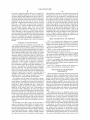
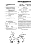
20
w
26
/
126
DATABASE
MGR,
AUTO-SENSE
\11s
MGR.
E
124/
%
FUNCTION
2
BLOCK DATA
MGR.
WIRING
FAULT
DIAGNOSTIC
MGR.
/ A
126
COMMUNICATIONS
\112
CONNECTION
115
FIELD DEVICE \
MGR.
1"
WIRING FAULT /128
DETSSIZIII'ION
‘
MGR.
DIAGNOSTIC
MGR,
LIVE LIST
\110
122 /
COMMUNICATION \108
MONITOR
/
4
‘20
y
COMMUNICATION
v
STACK
\104
[100
MGR.
LINK ACTIVE
SCHEDULE
MGR
PROCESSOR
102
U.S. Patent
Jun. 28,2005
Sheet 1 0f 7
US 6,912,671 B2
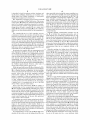
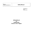
10
usER
USER
DATA
INTERFACE
INTERFACE
STORAGE
\
\
\
12
14
16
7
20
CONTROLLER \18
LINKING
DEvICE
\
28
SMART FIELD
DEVICE
\22
30 \
SMART FIELD _\
DEVICE
24
SMART FIELD
DEVICE
FIG. 1
\26
U.S. Patent
Jun. 28,2005
Sheet 3 0f 7
US 6,912,671 B2
—
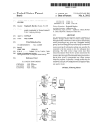
12a
/
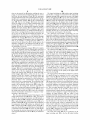
LED DRIVE _/ 154
CIRCUIT
158
160
162
/
/
/
OHMMETER
VOLTMETER
SIGNAL
(peak'w'peak)
GENERATOR
“r152
(DC)
154
166
168
/
j
/
NO'SE
METER
GROUND
FAULT
DETECTOR
CAPACITANCE
METER
SIGNAL {150
SWITCHING
UNIT
I
\3‘“
I
TO WIRING FAULT
To COMMUNICATION
DIAGNOSTIC MGR.
STACK
FIG. 3
U.S. Patent
Jun. 28,2005
Sheet 4 0f 7
US 6,912,671 B2
DISCONNECT BUS LINES
FROM COMMUNICATION /2°°
CIRCUITRY
204
/
202
REPORTWIRING FAULT
TO USER AT SYSTEM
NO
R BETWEEN SIGNAL
LINES (+ a. -) > 50K
LEVEL - POSSIBLE
SHORT + T0 -
OHMS?
YES
208
/
206
REPORT WIRING FAULT TO
R BETWEEN EACH SIGNAL LINE
(+ 8. -) AND SHIELD AND EACH
SIGNAL LINE AND GROUND
NO
USER AT SYSTEM LEVEL -
POSSIBLE SHORT, CHECK
LINES —
> 20 M OHMS?
YES
212
/
210
REPORT WIRING FAULT
c BETWEEN SIGNAL
TO USER AT SYSTEM
N0
LEVEL - POSSIBLE
LINES (+ a -) .8” F TO
MISSING OR EXTRA
TERMINATOR
YES
216
214
C BETWEEN EACH SIGNAL
LINE AND SHIELD AND EACH
SIGNAL LINE AND GROUND
/
REPORT WIRING FAULT TO USER
NO
YES
218
NO
ANY
REPORTED
FAULTS?
YES
FIG. 4A
AT SYSTEM LEVEL - POSSIBLE
POOR SHIELD CONNECTION,
CHECK LINES
U.S. Patent
Jun. 28,2005
Sheet 5 0f 7
US 6,912,671 B2
220
/
CONNECT BUS LINES TO
LINKING DEVICE
COMMUNICATION
CIRCUITRY
224
/
REPORT WIRING FAULT TO
DO VOLTAGE BETWEEN
USER AT SYSTEM
SIGNAL LINES (+ a -) 18.6
LEVEL-SUPPLY VOLTAGE
TO 19.4 v00?
OUT OF RANGE
228
/
REPORT WIRING FAULT TO
USER AT SYSTEM
' EAK-TO-PEAK SIGNAL
VOLTAGE (+ & -) 500 mV
LEVEL-INSUFFICIENT
SIGNAL STRENGTH
FIG. 4B
U.S. Patent
Jun. 28,2005
Sheet 6 6f 7
US 6,912,671 B2
302
/
REPORT FATAL
COMMUNICATION
FAULT TO USER
AT SYSTEM
LEVEL
YES
FATAL
COMMUNICATION
FAULT?
3
304
38
/
INVOKE
COMMUNICATION
REPORT
EXCESSIVE NOISE
FAULT PROCEDURE
T0 USER AT
SYSTEM LEVEL
1
SIGNAL LEVEL
OUT OF RANGE?
312
/
REPORT SIGNAL LEVEL
OUT OF RANGE TO USER
AT SYSTEM LEVEL
FIG. 5
U.S. Patent
Jun. 28,2005
Sheet 7 0f 7
US 6,912,671 B2
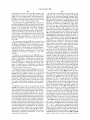
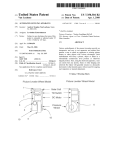
400
/
126
j
WIRING
D'SPLAY \406
402
/
MEMORY
DIAGNOSTIC
MANAGER
404
/
KEYPAD
408
PROCESSOR
30
WIRING FAULT
DETECTION
UNIT
POWER
SOURCE
\
12s
\ 3o
(Iv
rm’
FIG. 6
US 6,912,671 B2
1
2
WIRING FAULT DETECTION, DIAGNOSIS
to provide responsive signals via an analog output block to
AND REPORTING FOR PROCESS CONTROL
SYSTEMS
an actuator that modulates the position of a valve plug. Thus,
these function blocks may be communicatively linked to one
another to form a PID-based control loop that controls the
How of a ?uid through a valve.
Smart ?eld devices typically communicate using an open
FIELD OF THE INVENTION
protocol that is different from the protocol used by the
The present invention relates generally to process control
controllers Within a process control system. As a result, an
interface device such as an input/output (I/O) device or
systems and, more speci?cally, to automatically detecting,
diagnosing and reporting Wiring faults Within communica
tion segments of a process control system.
10
DESCRIPTION OF THE RELATED ART
devices enable the smart ?eld devices Within a segment to
Modern process control systems are typically
microprocessor-based distributed control systems (DCSs). A
traditional DCS con?guration includes one or more user
linking device is typically used to provide a communication
gateWay betWeen each segment (i.e., each interconnected
group of smart ?eld devices) and a controller. These linking
interoperate via a protocol data bus (e.g., a Fieldbus databus)
15
With the function blocks of a controller and With smart ?eld
devices connected to other segments of the process control
interface devices, such as Workstations, connected by a
system. Thus, these linking devices enable a seamless inte
databus (e.g., Ethernet) to one or more controllers. The
controllers are generally located physically close to a con
gration of smart ?eld devices Within a distributed process
control system because they enable the linking of ?eld
trolled process and are connected to numerous electronic
device information, such as function block information
monitoring devices and ?eld devices such as electronic
sensors, transmitters, current-to-pressure transducers, valve
resident in one or more of the ?eld devices, With function
block information resident in the controller or other ?eld
positioners, etc. that are located throughout the process.
In a traditional DCS, control tasks are distributed by
providing a control algorithm Within each of the controllers.
devices and controllers distributed throughout the process
control system.
While the protocol bus Wiring for the multitude of seg
The controllers independently execute the control algo
25
ments that are typically used Within a distributed process
control system is being installed, one or more bus Wires may
rithms to control the ?eld devices coupled to the controllers.
This decentraliZation of control tasks provides greater over
all system ?exibility. For example, if a user desires to add a
neW process or part of a process to the DCS, the user can add
be inadvertently connected to the Wrong terminal (i.e., the
Wrong signal port, poWer supply voltage, etc.), one or more
bus Wires may be left unconnected (i.e., an open-circuit
an additional controller (having an appropriate control
condition), and/or one or more bus Wires may be improperly
algorithm) connected to appropriate sensors, actuators, etc.
terminated. Additionally, even if all protocol bus Wiring is
Alternatively, if the user desires to modify an existing
process, neW control parameters or control algorithms may,
initially installed properly, one or more of the bus Wires may
become severed or shorted to another Wire or potential (e.g.,
for example, be doWnloaded from a user interface to an 35
a voltage source, ground line, etc.) during subsequent opera
appropriate controller via the databus.
tion of the process control system.
To provide for improved modularity and inter
Detecting, diagnosing and reporting a Wiring fault Within
manufacturer compatibility, process controls manufacturers
a segment is typically very dif?cult because current linking
have more recently moved toWard even further decentrali
devices cannot measure or analyZe the electrical character
Zation of control Within a process. These more recent 40 istics such as the resistance, capacitance, etc. of the segment
approaches are based on smart ?eld devices that communi
protocol bus or the amplitude, frequency, noise level, etc. of
cate using an open protocol such as the HART®,
the signals being transmitted via the segment protocol bus.
PROFIBUS®, WORLDFIP®, Device-Net®, CAN, and
As a result, users at the system level (e.g., at an operator’s
Fieldbus protocols. These smart ?eld devices are essentially
microprocessor-based devices such as sensors, actuators,
terminal having a graphical user interface) cannot easily
45
identify a Wiring fault on a particular segment and are
etc. that, in some cases, such as With Fieldbus devices, also
typically only informed by the system that the overall
perform some control loop functions traditionally executed
process is not operating properly and/or that a communica
by a DCS controller. Because some smart ?eld devices
tion error has occurred. For example, in the case Where tWo
or more protocol bus Wires Within a segment become shorted
to one another (or to another common potential), the con
troller may report to the user via a user interface that the
smart ?eld devices on that segment are not responding.
provide control capability and communicate using an open
protocol, ?eld devices from a variety of manufacturers can
communicate With one another on a common digital databus
and can interoperate to execute a control loop Without the
intervention of a traditional DCS controller.
As is Well knoWn, smart ?eld devices such as, for
example, Fieldbus devices, may include one or more logical
function blocks that perform control functions or portions of
a control function. These function blocks may, for example,
HoWever, the controller typically does not provide the user
With any additional information that could be used to
55
determine Why the devices failed to respond. In fact, neither
the controller nor the linking device can measure the resis
tance of the bus Wires to detect the shorted condition,
perform analog input functions, analog output functions,
thereby preventing the detection and reporting of such a
proportional-integral-derivative (PID) control functions, or
Wiring fault.
any other desired control functions. As discussed in greater
detail beloW, the function blocks Within a smart ?eld device
segment protocol bus Wiring fault is typically accomplished
With existing process control systems, the diagnosis of a
by dispatching a ?eld technician to visually inspect each
suspect segment. Additionally, the ?eld technician typically
may be communicatively linked With other function blocks
Within that smart ?eld device or With function blocks Within
other smart ?eld devices to carry out any desired control
function. For example, an analog input block may be used to
uses a variety of test equipment such as an ohmmeter, a
65
voltmeter, an oscilloscope, a signal generator, a capacitance
monitor a ?uid ?oW via a How sensor and a PID block may
meter, etc., to measure and compare the electrical charac
process a ?uid ?oW value provided by the analog input block
teristics of the segment protocol bus to expected ranges or
US 6,912,671 B2
3
4
levels and to assess the qualities such as, for example, the
and adapted to be executed by the processor that causes the
Wiring fault detection unit to connect a signal line of the
protocol bus to one of the plurality of measurement blocks.
noise level, amplitude, frequency, etc. of the communication
and poWer supply signals transmitted via the bus Wires. The
measured electrical characteristics of the segment protocol
bus and the measured electrical characteristics of the signals
The system may further include a second routine stored on
the computer readable medium and adapted to be executed
by the processor that causes the Wiring fault detection unit
transmitted via the bus Wires may be used by the ?eld
technician to diagnose the speci?c nature or type of a Wiring
fault (e.g., a short circuit, an open circuit, an improper
termination, etc.), thereby enabling the ?eld technician to
take appropriate corrective action. Thus, With existing
to measure an electrical characteristic associated With the
10
systems, a ?eld technician typically does not have any
information, other than that a communication problem
exists, indicating on Which segment the Wiring fault has
occurred or What type of Wiring fault is likely to have caused
the communication problem. As a result, the ?eld technician
must carry a relatively large amount of equipment to the
15
protocol bus using the one of the plurality of measurement
blocks. Still further, the system may include a third routine
stored on the computer readable medium and adapted to be
executed by the processor that determines a type of the
Wiring fault based on the measured electrical characteristic.
Additionally, the system may include a fourth routine stored
on the computer readable medium and adapted to be
executed by the processor that automatically reports the type
of the Wiring fault to the user interface.
location of each suspect (or possibly every) segment bus to
BRIEF DESCRIPTION OF THE DRAWINGS
guarantee that a proper diagnosis can be made at the segment
location.
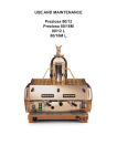
FIG. 1 is a schematic block diagram of an exemplary
SUMMARY OF THE INVENTION
process control system having a linking device that detects,
A Wiring fault detection, diagnostic and reporting tech
nique enables linking devices (i.e., the interfaces betWeen
diagnoses and reports segment protocol bus Wiring faults;
smart ?eld devices and controllers) Within a process control
system to measure the electrical characteristics of a segment
linking device shoWn in FIG. 1;
FIG. 2 is a more detailed exemplary block diagram of the
25
protocol bus and the signals transmitted via the protocol bus.
The technique described herein also enables the linking
devices to analyZe the measured electrical characteristics to
determine Whether a Wiring fault exists on a protocol bus
one manner in Which the linking device shoWn in FIGS. 1
and 2 may be used to detect, diagnose and report segment
connected to that linking device. Additionally, the technique
protocol bus Wiring faults;
described herein enables the linking devices to report the
Wiring fault information such as electrical characteristic
FIG. 5 is an exemplary ?oW diagram depicting another
manner in Which the linking device shoWn in FIGS. 1 and 2
information, signal quality information, diagnostic
information, etc. to respective controllers Which, in turn,
may automatically report this Wiring fault information to a
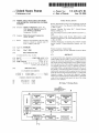
FIG. 3 is a more detailed exemplary block diagram of the
Wiring fault detection unit shoWn in FIG. 2;
FIGS. 4A and 4B are exemplary ?oW diagrams depicting
may be used to detect, diagnose and report segment protocol
bus Wiring faults; and
35
user via a user interface. In this manner, the Wiring fault
FIG. 6 is an exemplary schematic block diagram of a
portable Wiring fault detection and diagnosis device.
detection, diagnostic and reporting technique described
herein enables a user to perform commissioning activities
such as, for example, Wiring check outs, in an ef?cient and
convenient manner from an operator’s terminal, thereby
reducing or eliminating the need for a ?eld technician to
DESCRIPTION OF THE PREFERRED
EMBODIMENTS
40
While a technique for detecting, diagnosing and reporting
physically inspect every segment throughout the process
control system, as is required With current systems.
In accordance With one aspect of the invention, a system
and method for use Within a process control system having
Wiring faults Within a distributed process control system is
described in detail in conjunction With a process control
45
system that implements process control functions using
Fieldbus devices, the Wiring fault detection, diagnosis and
diagnostic manager. The system and method may connect a
signal line of the protocol bus to one of the plurality of
measurement blocks. Additionally, the system and method
reporting technique described herein may be used With
process control systems that perform control functions using
other types of ?eld devices and communication protocols,
including protocols that rely on other than tWo-Wire buses
and protocols that support only analog or both analog and
digital communications, such as those mentioned previ
may measure an electrical characteristic associated With the
ously.
protocol bus using the one of the plurality of measurement
blocks and may send the measured electrical characteristic
to the Wiring fault diagnostic manager. Still further, the
system and method may determine a type of the Wiring fault
The Fieldbus protocol is an all-digital, serial, tWo-Way
communication protocol that provides a standardiZed physi
a user interface, a controller, and a protocol bus, includes a
Wiring fault detection unit having a plurality of measurement
blocks and a signal sWitching unit, and a Wiring fault
55
cal interface to a tWo-Wire loop or bus interconnecting ?eld
equipment such as sensors, actuators, controllers, valves,
based on the measured electrical characteristic and may
etc. located in an instrumentation or process control envi
automatically report the type of the Wiring fault to the user
interface.
In accordance With another aspect of the invention, a
ronment of, for example, a factory or a plant. The Fieldbus
protocol provides, in effect, a local area netWork for ?eld
devices Within a process, Which enables these ?eld devices
to interoperate to perform control functions at locations
distributed throughout a process and to communicate With
one another before and after the performance of these
control functions to implement an overall control strategy.
system for detecting a Wiring fault for use Within a process
control system having a user interface, a controller, a pro
tocol bus, and a processor, includes a Wiring fault detection
unit. The Wiring fault detection unit may include a plurality
of measurement blocks and a signal sWitching unit. The
system may further include a computer readable medium
and a ?rst routine stored on the computer readable medium
65
Although the Fieldbus protocol is a relatively neW all-digital
communication protocol developed for use in process con
trol systems, the Fieldbus protocol is knoWn in the art and
US 6,912,671 B2
5
6
is described in detail in numerous articles, brochures and
other smart ?eld device having link master capability (e.g.,
speci?cations published, distributed, and available from,
one of the ?eld devices 22—26), must actively schedule and
control communications on the protocol bus 30. The LAS
stores and updates a communication schedule (i.e., a link
among others, the Fieldbus Foundation, a not-for-pro?t
organization headquartered in Austin, Tex.
FIG. 1 illustrates an exemplary process control system 10
that uses, for example, Fieldbus ?eld devices. The process
control system 10 includes user interfaces 12 and 14, Which
may be, for example, Workstations connected in a commu
active schedule) containing the times that each function
block of each device is scheduled to start periodic (i.e.,
synchronous) communication activity on the bus 30 and the
length of time for Which this communication activity is to
nication netWork to a number of other devices such as a data
device on the bus 30, other smart ?eld devices having link
master device capability (such as the device 22) may serve
as backup LASs and become active When, for example, the
storage device 16 and a controller 18 via a system level
databus 20. The system level databus 20 may be an Ethernet
databus or any other databus suitable for the transmission of
data.
The controller 18 may be a DCS controller and may
communicate With the user interfaces 12 and 14 using a
occur. While there may be one and only one active LAS
10
current LAS fails.
15
proprietary communication protocol, or in any other suitable
manner, via the system level databus 20. For example, the
controller 18 may send alarm, status and diagnostic infor
mation to the user interfaces 12 and 14 and may additionally
and one or more asynchronous communications for one or
more of the function blocks or devices active on the bus 30.
To conserve bandWidth on the bus 30, communications
receive user commands/requests from the user interfaces 12
betWeen tWo function blocks Within a single device need not
and 14 via the system level databus 20. The controller 18
may further include control algorithms for use in controlling
be published on the bus 30 and may be accomplished using
communication links that are completely internal to the
device.
?eld devices that are connected to the controller 18 in any
conventional or any other desired manner.
In particular, the controller 18 is in communication With
smart ?eld devices 22—26 via a linking device 28. The ?eld
25
devices 22—26 are connected in a communication netWork
non-proprietary protocol. More speci?cally, the linking
With one another and the linking device 28 to execute one or
device 28 monitors all the communications on the smart
more process control loops either in conjunction With or
independently from the controller 18. The smart ?eld
devices and protocols could be used as Well.
While the smart ?eld devices 22—26 are illustrated in FIG.
?eld device protocol bus 30 and processes the monitored
communications so that function block information sub
scribed to by the controller 18 may be conveyed to the
35
devices are connected to the same pair of Wires, the Fieldbus
ated With the ?eld device protocol bus 30 can be generated
by detecting a deviation betWeen the actual communications
40
nected to a controller or a host via a separate tWo-Wire pair
(similar to typical 4—20 mA analog DCS systems), and tree
45
a junction box or a termination area in one of the ?eld
devices Within a process control system.
Each of the smart ?eld devices 22—26 is capable of
communicating over the non-proprietary protocol databus
30 and is capable of independently performing one or more
process control functions using data acquired by the ?eld
device from the process or from a different ?eld device via
communication signals on the bus 30. In particular, Fieldbus
devices are capable of directly implementing portions of an
overall control strategy that, in the past, Were performed
entirely Within a DCS controller.
on the bus 30 and the scheduled communications in accor
dance With a link active schedule that is stored in the linking
device 28.
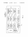
FIG. 2 is a more detailed exemplary block diagram of the
point-to-point connections, in Which each device is con
or “spur” connections in Which each device is connected to
a common point in a tWo-Wire bus that may be, for example,
controller 18 as needed, identi?cation information (e.g.,
addresses, tags, etc.) associated With a ?eld device may be
conveyed to a user terminal, and communication diagnostic
information (such as timing and linking problems) associ
1 as being connected to the non-proprietary protocol databus
30 in a standard bus-type con?guration, in Which multiple
protocol alloWs other device/Wire topologies including
Generally speaking, the linking device 28 provides a
communication gateWay or bridge betWeen the smart ?eld
devices 22—26 that communicate using a non-proprietary
protocol and a controller 18 that may not be using the
via a non-proprietary protocol databus 30 and communicate
devices 22—26 may be, for example, Fieldbus devices, in
Which case the non-proprietary protocol databus 30 employs
the Fieldbus signal protocol. HoWever, other types of
Generally speaking, communication activities over the
bus 30 are divided into repeating macrocycles, each of
Which includes one synchronous communication for each
function block (having external links) active on the bus 30
linking device 28 shoWn in FIG. 1. The linking device 28
alloWs an integration of the ?eld devices 22—26 (FIG. 1)
With the process control system 10 (FIG. 1). For instance, in
addition to providing conventional communication links
betWeen the function block parameters of the smart ?eld
devices 22—26 on the non-proprietary protocol bus 30, the
linking device 28 also enables communication links betWeen
function blocks of the ?eld devices 22—26 and function
blocks that reside Within the controller 18. Thus, the linking
device 28 alloWs a user to de?ne control loops using
combinations of function blocks that reside in the controller
55 18 and in one or more of the ?eld devices 22—26.
As noted above, the linking device 28 provides diagnostic
capabilities for facilitating the troubleshooting of commu
To implement any control strategy using function blocks
nication problems on the ?eld device protocol bus 30. The
distributed throughout a process control system, the execu
linking device 28 monitors and analyZes substantially all of
tion of the function blocks must be precisely scheduled With
respect to the execution of other function blocks in a
the communications on the protocol bus 30 and uses the link
active schedule as a communication template to identify
communication and linking problems, such as Where a ?eld
device fails to provide fresh data at the correct time to the
correct recipient, or fails to provide any data. Because the
particular control loop. Likewise, communication betWeen
different function blocks must be precisely scheduled on the
bus 30 so that the proper data is provided to each function
block before that block executes.
For communication to occur on the bus 30, the link active
scheduler (LAS), Which can be the linking device 28 or any
65
linking device 28 can communicate freely With the control
ler 18, the diagnostic information can be easily conveyed to
the user at the system level (i.e., a user interface), Which
US 6,912,671 B2
7
8
eliminates the need for the user to locally monitor and
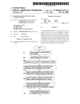
108, a connection manager 110, an auto-sense manager 112,
a ?eld device manager 114, a function block data manager
116, a database manager 118, a link active schedule manager
120, a live list manager 122, a communications diagnostic
manually determine ?eld device communication problems.
The linking device 28 automatically subscribes to all
communications on the protocol bus 30 using, for example,
the link active schedule. Because the link active schedule
contains a communication template for the protocol bus 30,
the linking device 28 can determine the precise times at
manager 124, and a Wiring fault diagnostic manager 126.
The linking device 28 also includes a Wiring fault detection
unit 128 Which, as described in greater detail beloW, includes
Which particular ?eld devices are scheduled to communicate
functional blocks that can measure the electrical character
on the bus 30. Thus, by comparing the link active schedule
to the actual communications on the bus 30, deviations from
the link active schedule can be identi?ed as possible com
10
the Wiring fault detection unit 128 is communicatively
coupled to the Wiring fault diagnostic manager 126 and
provides electrical characteristic information to the Wiring
fault diagnostic manager 126 for further processing and
munication problems With particular ?eld devices. These
deviations from the link active schedule can be used by the
linking device 28 to generate communication diagnostic
information associated With the smart ?eld devices 22—26
that may be useful in troubleshooting and/or con?guring the
istics of the bus 30 and the electrical characteristics of the
signals being transmitted on the bus 30. As shoWn in FIG. 2,
15
reporting to a user at the system level.
A general outline of the operations of the above-noted
functional blocks 100 Will be provided beloW and Will be
process control system 10 (FIG. 1). For example, the diag
nostic information may include linking problems such as a
failure of a device to transmit data properly to a subscribing
folloWed With a more detailed discussion of hoW the various
device and/or may include timing problems that may be
identi?ed using statistical information such as, for example,
functional blocks cooperate to provide communication
the number of times a device has failed to provide fresh data
to a subscribing device. Of course, a Wide variety of other
communication-related diagnostic information can be gen
remotely troubleshoot a segment protocol bus from, for
troubleshooting capabilities that enable a system user to
example, a user interface.
The communication stack 104 is a conventional Fieldbus
erated by making appropriate comparisons and analyses of
the actual and scheduled communication activities.
25
The linking device 28 also provides Wiring fault
detection, diagnostic and reporting capabilities. As Will be
communication stack, Which alloWs the functional blocks
100 to communicate (i.e., receive and send) information
along the protocol bus 30 to the ?eld devices 22—26 (FIG. 1).
The communication monitor 108 monitors all communica
described in greater detail beloW, the linking device 28 can
tions on the bus 30 and routes the information to one or more
measure the electrical characteristics such as, for example,
of the other functional blocks 110-124 for further process
the resistance, capacitance, etc. of the protocol bus 30 and
ing.
can also measure the electrical characteristics of the signals
being transmitted via the bus 30, such as, for example, the
amplitude, frequency, noise level, etc. of the signals. The
linking device 28 may further process or analyZe these
measured electrical characteristics to determine Whether a 35
Wiring fault exists on the bus 30 and may diagnose the
speci?c nature of a Wiring fault. For example, the linking
The connection manager 110 uses the communication
stack 104 to coordinate communications on the protocol bus
30. For instance, the connection manager 110 may use the
link active schedule, a copy of Which is stored in the memory
106, to send/receive information from the ?eld devices
22—26 during either asynchronous or synchronous commu
device 28 may measure one or more resistances associated
nication intervals of a macrocycle on the bus 30. Some of the
With one or more bus Wires or signal lines of the bus 30 and,
based on a comparison of the measured resistances to
information transmitted synchronously may include func
tion block information needed by or sent by function blocks
40
predetermined resistance values or ranges of resistance
values, determine that a Wiring fault exists on one or more
of the bus Wires (e.g., a short circuit, an open circuit, an
improper termination, etc.). The linking device 28 may then
convey or report the detected Wiring fault information,
Which may include Wiring fault diagnostic information, to
the controller 18 Which, in turn, may report this information
45
Within the controller 18. In this manner, the connection
manager 110 alloWs the linking device 28 to emulate the
synchronous communication characteristics of a ?eld
device.
The ?eld device manager 114 controls the doWnloading of
con?guration information to the Fieldbus devices 22—26.
For example, virtual communication relationships (VCRs),
to the user via one or more of the user interfaces 12 and 14.
addresses, tags, etc. may be sent by a user via the user
As shoWn in FIG. 2, the linking device 28 includes a
plurality of functional blocks 100 Which are controlled by a
processor 102 to publish and subscribe to communications
on the protocol bus 30 via a communications stack 104 and
interfaces 12 and 14, the controller 18, and the linking
to enable detection, diagnosis and automatic system-level
reporting of Wiring faults on the protocol bus 30. The
functional blocks 100 may be implemented using any
desired combination of hardWare and softWare. Generally,
the functional blocks 100 may be ef?ciently implemented
device 28 to one or more of the ?eld devices 22—26.
55
The link active schedule manager 120 controls the loading
of the link active schedule in any other link active schedulers
that may be present on the protocol bus 30. The database
manager 118 stores Fieldbus information for reporting to the
controller 18. The Fieldbus information stored in the data
base manager 118 may include vieW list information, data
using the processor 102 to execute a number of softWare
subscribed to by the controller 18 (i.e., function block
information), statistical information relating to the commu
code segments or modules that are retrieved from a local
nications on the bus 30, etc. The communications diagnostic
computer readable memory 106. HoWever, other combina
manager 124 detects communication problems (e.g., timing
tions of hardWare and softWare using, for example, algo
rithm speci?c integrated circuits (i.e., ASICs) or other types
problems) on the protocol bus 30 and reports the problems
of hardWare may be used to accomplish the same functions
controller 18 and the system level netWork 20.
The auto-sense manager 112, the live list manager 122
and the communications diagnostic manager 124 Work
to the user via one of the user interfaces 12 and 14, the
Without departing from the scope and the spirit of the
invention.
The functional blocks 100 Within the linking device 28
include, but are not limited to, a communication monitor
65
together to automatically analyZe/detect and report to the
user communication problems associated With communica
US 6,912,671 B2
9
10
The signal sWitching unit 150 includes signal sWitching
tions on the protocol bus 30, thereby enabling the user to
engage in communication troubleshooting from the system
level (e.g., the user interface 12 and 14). The auto-sense
circuitry that, in response to commands from the Wiring fault
diagnostic manager 126, connects one or more of the signal
manager 112 uses the link active schedule and the live list to
lines or Wires of the bus 30 to one or more of the measure
identify and to communicate With the ?eld devices 22—26,
via the connection manager 110 and the communication
stack 108. The live list manager 122 detects When ?eld
ment blocks 158—168. Additionally, the signal sWitching unit
150 may connect the signal lines of the bus 30 to commu
nication circuitry (i.e., the physical layer of the communi
cation stack 104) Within the linking device 28. The signal
sWitching unit 150 may be implemented using electrome
devices are added to or are no longer communicating on the
protocol bus 30 and reports changes to the auto-sense
manager 112 and the communications diagnostic manager
124. The auto-sense manager 112 may collect and produce
identi?cation information such as addresses, tags, serial
numbers, functional roles (e.g., Whether the ?eld device is a
10
analog multiplexers, etc. Of course, any other suitable signal
sWitching devices may be used instead Without departing
from the scope and the spirit of the invention.
The ohmmeter block 158 is preferably, but not
basic device or a bridge device), etc. that are associated With
one or more of the ?eld devices 22—26 and compare the
identi?cation information to commissioning (i.e.,
chanical devices such as relays, reed sWitches, etc. and/or
may use solid state devices such as discrete transistors,
15
con?guration) information stored in the database manager
118 and/or the memory 106. Based on the comparison, the
necessarily, con?gured to measure resistances betWeen Zero
ohms and at least tWenty megaohms by sending a relatively
small direct current (DC) through a selected pair of signal
lines of the bus 30 and measuring a resultant voltage drop.
HoWever, due to the relatively small DC current used by this
auto-sense manager 112 determines if there is a discrepancy,
such as, for example, if a device has been added to or
removed from the protocol bus 30. To further improve the
diagnostic capabilities of the linking device 28, the auto
resistance measurement technique, the ohmmeter block 158
sense manager 112 may be adapted to automatically report
requires the signal sWitching unit 150 to disconnect the
signal lines of the bus 30 from the communication circuitry
any discrepancy to the user.
Within the linking device 28 While the ohmmeter block 158
The Wiring fault diagnostic manager 126 receives signals
indicative of measured electrical characteristics associated
With the signal lines or Wires of the bus 30 from the Wiring
fault detection unit 128 and further processes these signals
carries out the resistance measurement.
25
to determine Whether there are any Wiring faults on the bus
The voltmeter block 160, on the other hand, is con?gured
to measure peak-to-peak alternating current (AC) voltage,
DC voltage, AC root mean squared (RMS) voltage, etc.
While the signal lines of the bus 30 are connected to the
30. In particular, the Wiring fault diagnostic manager 126
communication circuitry of the linking device 28 and While
may determine that a Wiring fault exists on a particular
Fieldbus communications are active on the bus 30. Con
segment protocol bus Within the system 10 (such as the bus
30) and may further identify the speci?c nature or type of the
Wiring fault. For example, the Wiring fault diagnostic man
necting the voltmeter block 160 to the signal lines of the bus
30 in this manner does not have any practical effect on active
communications because the voltmeter block 160 has a high
ager 126 may determine that a particular one of the signal
lines of the bus 30 is shorted, is an open circuit, is improp
erly terminated, is excessively noisy, etc. Any such Wiring
fault information generated by the Wiring fault diagnostic
input impedance (e.g., greater than one megaohm). In
35
any DC supply voltage on the bus 30, the signal amplitude
or strength (using, for example, a peak-to-peak voltage
manager 126 may be communicated to the controller 18
Which, in turn, may report the Wiring fault information to the
user via one of the user interfaces 12 and 14. Thus, the
Wiring fault detection unit 128 and the Wiring fault diag
operation, the voltmeter block 160 may be used to measure
40
measurement function) on the bus 30, or any other voltage
that may be indicative of the quality of the signals trans
mitted via the bus 30.
nostic manager 126 enable a system user at one of the
The signal generator block 162 is con?gured to generate
interfaces 12 and 14 to identify a Wiring fault Within any
AC signals that may be transmitted via one or more signal
segment protocol bus of the process control system 10,
thereby eliminating the requirement for a ?eld technician to
voltmeter block 160 to determine the transmission charac
physically inspect every communication segment during
lines of the bus 30 and measured by, for example, the
45
system check out or commissioning. The Wiring fault diag
nostic manager 126 also sends control signals and com
mands to the Wiring fault detection unit 128 to control the
Waveforms, impulses, step function Waveforms, frequency
modulated Waveforms, amplitude modulated Waveforms,
operations of the Wiring fault detection unit 128. For
example, the Wiring fault diagnostic manager 126 may send
etc. Thus, the signal generator block 162 may be used to
commands to the Wiring fault detection unit 128 that cause
the Wiring fault detection unit 128 to carry out a particular
measure the response of the bus 30 to various types of
communications or signals, thereby enabling these measure
ments to be used to diagnose a variety of Wiring faults. For
example, the signal generator 162 may output a ?xed
electrical characteristic measurement or sequence of mea
surements at particular times.
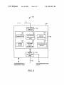
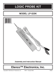
FIG. 3 is a more detailed exemplary block diagram of the
Wiring fault detection unit 128 shoWn in FIG. 2. As shoWn
in FIG. 3, the Wiring fault detection unit 128 includes a
teristics of the bus signal lines. The signal generator block
162 may provide any variety of Waveforms desired, such as,
for example, square Waves, saWtooth Waveforms, sinusoidal
55 amplitude sinusoidal current Waveform on one or more of
the signal lines of the bus 30 and the resulting peak-to-peak
voltage may be measured by the voltmeter block 160. The
signal sWitching unit 150, a plurality of measurement blocks
152, a light-emitting diode (LED) drive circuit 154 and a
peak-to-peak voltage measured by the voltmeter block 160
plurality of LEDs 156. By Way of example only, the plurality
Where the peak-to-peak voltage is substantially near Zero
may be indicative of the load on the bus 30 and, in a case
of measurement blocks 152 includes an ohmmeter block
volts, it may be indicative of a short circuit on one or more
158, a voltmeter block 160, a signal generator block 162, a
noise meter block 164, a ground fault detector block 166 and
a capacitance meter block 168. Of course, any other blocks
for measuring the electrical characteristics of the bus 30 or
of the signals transmitted via the bus 30 may be included if
desired.
bus lines. In general, use of the signal generator block 162
to transmit signals on the bus 30 requires the signal sWitch
ing unit 150 to disconnect the communication circuitry of
the linking device 28 from the bus 30.
65
The noise meter block 164 may be connected via the
signal sWitching unit 150 to the bus 30 While Fieldbus
US 6,912,671 B2
11
12
The LED drive circuit 154 may receive signals or com
communications are active on the bus 30 to measure noise
levels present on one or more signal lines of the bus 30
Within one or more frequency bands. The noise meter block
mands from one or more of the measurement blocks 152
164 may use any conventional or any other suitable ?ltering
illuminate one or more of the LEDs 156. Each of the LEDs
techniques to selectively measure peak noise poWer, average
156 may uniquely correspond to a particular type of Wiring
fault and/or may correspond to a particular signal line of the
bus 30. For example, one of the LEDs 156 maybe illumi
and/or from the Wiring fault diagnostic manager 126 to
noise poWer, etc. Within a desired frequency band.
The ground fault detector block 166 may be connected via
the signal sWitching unit 150 to the bus 30 When the signal
lines of the bus 30 are disconnected from the communication
circuitry of the communication stack 104 to determine
Whether the ground signal line or Wire of the bus 30 is
10
fault diagnostic manager 126 determines (using, for
example, the capacitor meter block 168) that the “+” signal
improperly connected to another potential. The ground fault
detector block 166 detects an unusually loW resistance (e.g.,
a short) betWeen a bus signal line and system ground such
as, for example, the unusually loW resistance that Would
result from the ground signal line or Wire of the bus 30
line is improperly terminated, still another one of the LEDs
156 may be illuminated When the Wiring fault diagnostic
15
the bus 30.
The capacitance meter block 168 may be connected via
desired to provide a local (i.e., at the segment location)
the signal sWitching unit 150 (When the signal lines of the
visual indication that particular Wiring faults exist, thereby
bus 30 are disconnected from the communication circuitry
of the linking device 28) to measure a capacitance betWeen
a pair of bus lines. The capacitance meter block 168 may be
techniques that measure a charging rate (i.e., a time-based
enabling a ?eld technician to quickly identify the location
and nature of a segment protocol bus Wiring fault.
FIGS. 4A and 4B are exemplary ?oW diagrams depicting
25
protocol bus Wiring faults. Preferably, but not necessarily,
technique.
the blocks shoWn in FIGS. 4A and 4B are carried out by the
In general, the measurement blocks 158—168 may be
diagnostic manager 126 Working in conjunction With the
implemented using any suitable technique for measuring the
Wiring fault detection unit 128. Alternatively, some of the
blocks shoWn in FIGS. 4A and 4B may be carried out by the
electrical characteristics of signal lines and signals trans
mitted via signal lines. For example, the measurement
controller 18 and/or one or both of the user interfaces 12 and
14. Furthermore, While the Wiring fault diagnostic manager
126 is depicted as residing entirely With the linking device
35
scope and the spirit of the invention.
Although the measurement blocks 158—168 are shoWn by
40
for example, digital ?ltering techniques, spectral analysis
any other device Within the process control system 10.
As shoWn in FIG. 4A, block 200 disconnects the signal
lines of the segment protocol bus 30 from the communica
tion circuitry (i.e., the physical layer of the communication
implemented using a digital oscilloscope block that converts
bus signals to digital values and processes these digital
values to measure voltages and/or to measure noise using,
28, some or all of the functions of the Wiring fault diagnostic
manager 126 may instead reside Within the controller 18,
Within one or both of the user interfaces 12 and 14, or Within
Way of example as separate functional blocks, one or more
of the measurement functions carried out by the blocks
158—168 may be combined if desired. For example, the
voltmeter block 160 and the noise meter block 164 may be
one manner in Which the linking device 28 shoWn in FIGS.
1 and 2 may be used to detect, diagnose and report segment
technique) or that measure an impedance, or any other
blocks 158—168 may be implemented using digital signal
processing techniques or analog signal processing tech
niques or, alternatively, any combination of analog and
digital processing techniques Without departing from the
manager 126 determines (using, for example, the voltmeter
block 160) that the signal strength measured betWeen the “+”
and “—” signal lines is beloW a minimum predetermined
threshold, etc. Of course, the LED drive circuit 154 and the
LEDS 156 may be con?gured to illuminate in any manner
shorting to a shield line or to any other signal line or Wire of
implemented using any conventional technique such as
nated When the ohmmeter block 158 detects a short circuit
betWeen the “+” and “—” signal lines of the bus 30, another
one of the LEDs 156 may be illuminated When the Wiring
45
techniques (e.g., fast Fourier transform based techniques),
etc.
Additionally, While some of the measurement blocks
158—168 are described as being connected to the bus 30
stack 104) of the linking device 28. Block 202 uses the
ohmmeter block 158 (FIG. 3) to measure the resistance
betWeen the “+” and “—” signals lines of the bus 30 and
determines Whether the measured resistance is greater than
50 kilohms (kohms). If the measured resistance is greater
than 50 kohms, control passes to block 206. On the other
hand, if the measured resistance is less than or equal to 50
kohms, control passes to block 204. Block 204 reports a
Wiring fault to the user at a system level and indicates that
ing asynchronous Fieldbus communication intervals, Which
the “+” and “—” signals lines of a particular segment (e.g.,
the segment associated With the bus 30) may be shorted to
each other and then passes control to block 206. To report
the Wiring fault to the user at the system level, the diagnostic
manager 126 may convey the Wiring fault information to the
controller 18 Which, in turn, may convey the Wiring fault
enables the Fieldbus devices on the bus 30 to communicate
information to one or both of the user interfaces 12 and 14.
in an unimpaired manner during scheduled synchronous
intervals. Alternatively, these measurement blocks may be
While communications are inactive, thereby preventing these
measurement blocks from interfering With communications,
other methods of preventing interference may be used
instead. For example, measurement blocks that could inter
fere With Fieldbus communications may be connected dur
55
scheduled to perform measurement activities during particu
Block 206 measures the resistances betWeen the each of
the “+” and “—” signal lines and the shield line of the bus 30.
Additionally, block 206 measures the resistances betWeen
lar synchronous intervals in a manner that does not interfere
With other synchronous communications on the bus 30. In
the “+” and “—” signal lines and system ground potential
(e.g., a system grounding bar). Block 206 then determines
any event, it should be recogniZed that it is not necessarily
Whether any of the measured resistances is greater than 20
required that the Wires or lines of the bus 30 are discon
nected from the communication stack 104 While resistance
measurements, capacitance measurements, or any other
measurements are being made.
megaohms (Mohms) and, if any of the resistances measured
65
by block 206 is greater than 20 Mohms, control passes to
block 210, otherWise, control passes to block 208. Block 208
reports a Wiring fault to the user at the system level and
US 6,912,671 B2
14
13
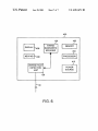
FIG. 5 is an exemplary ?oW diagram depicting another
indicates that a short circuit may exist between particular
signals lines of a particular segment. If multiple faults, such
manner in Which the linking device 28 shoWn in FIGS. 1 and
as multiple shorts, are found, then block 208 reports all of
2 may be used to detect, diagnose and report segment
protocol bus Wiring faults. Block 300 determines if a fatal
the faults to the user at the system level. Block 208 then
passes control to block 210.
Block 210 measures the capacitance betWeen the “+” and
communication fault has occurred on the bus 30. Fatal
communication faults include those faults Which preclude
the ?eld devices on a segment protocol bus from interoper
ating properly. Fatal communication faults may be detected
“—” signal lines and compares the measured capacitance
value to a predetermined range of capacitance values such
as, for example, 0.8 microfarads
to 1.2 pF. If the
capacitance measured by block 210 falls outside of the
predetermined range of capacitance values, control passes to
block 212, otherWise, control passes directly to block 214.
by comparing the actual communications (and the timing of
10
Block 212 reports a Wiring fault to the user at the system
level and indicates that a particular segment may not be
properly terminated. Typically, a measured capacitance
value of less than 0.5 pF indicates that there is no terminator
coupled to the segment, Whereas a measured capacitance
value of 2 pF indicates that tWo terminators (i.e., an extra
terminator) are coupled to the segment. Block 212 then
passes control to block 214.
Block 214 measures the capacitance value betWeen the
“+” and “—” signal lines and the shield line and betWeen the
“+” and “—” signal lines and system ground. If any of the
measured capacitance values are less than 300 nanofarads
15
the communications) to scheduled communications stored
Within the link active schedule. For example, if a device
failed to communicate at a scheduled time according to the
link active schedule, block 300 may determine that a fatal
communication fault has occurred. If a fatal communication
fault has occurred, control passes to block 302. Block 302
reports the fatal communication error to the user at the
system level and block 302 then passes control to block 304.
Block 304 invokes a communication fault diagnosis proce
dure. For example, block 304 may invoke the procedure
20
depicted in FIGS. 4A and 4B, thereby enabling the system
user to determine if the communication fault is a result of a
Wiring related problem.
If block 300 does not detect a fatal communication error,
control passes to block 306. Block 306 measures the noise
(nF), block 214 passes control to block 218, otherWise, block 25 level on the bus 30 and compares the measured noise level
to a predetermined threshold value. If the measured noise
214 passes control to block 216. Block 216 reports a Wiring
level is greater than the predetermined threshold level,
fault to the user at the system level and indicates that a poor
control passes to block 308, otherWise, control passes to
shield connection may be present on those lines (Within a
block 310. Block 308 reports to the user at the system level
particular segment) having excessive capacitances (i.e.,
greater than 300 nF). After block 216 reports Wiring faults, 30 that excessive noise is present on the bus 30 and then passes
control to block 310.
the procedure terminates.
Block 218 determines if any of blocks 204—212 have
reported a Wiring fault, if a fault has been reported, the
procedure terminates, otherWise, if no faults have been
reported, then control passes to block 220. Block 220
Block 310 measures the signal level (e.g., the peak-to
35
reconnects the lines of the bus 30 to the communication
circuitry (i.e., the physical layer Within the communication
stack 104) of the linking device 28. As a result of this
connection, poWer is supplied to the ?eld devices 22—26 and
Fieldbus communications betWeen the ?eld devices 22—26
40
returns control to block 300.
The Wiring fault detection, diagnosis and reporting tech
nique described above by Way of example in connection
With FIGS. 4A and 4B may be used during commissioning
and the controller 18 may resume. Block 220 then passes
control to block 222.
Block 222 measures the DC voltage betWeen the “+” and
“—” signal lines of the bus 30 and, if the measured DC
voltage falls betWeen 18.6 volts DC and 19.4 volts DC,
control passes to block 226, otherWise, control passes to
peak voltage) across the “+” an
signal lines of the bus
30 and compares the measured signal level to a predeter
mined range of values. If the measured signal level falls
outside of the predetermined range of values, control passes
to block 312, otherWise, control returns to block 300. Block
312 reports that the measured signal level is outside of the
predetermined range to the user at the system level and then
of the system 10 (FIG. 1), thereby eliminating the require
45
block 224. Block 224 reports a Wiring fault to the user at the
ment for a ?eld technician to physically inspect the Wiring
of the bus 30 or the Wiring of any other segment protocol bus
Within the system 10. In other Words, the system 10 may be
commissioned in an economical manner by a user stationed
system level and indicates that the poWer supplied on the bus
30 is out of range. Block 224 then passes control to block
226.
at one of the user interfaces 12 and 14. Further, the technique
may be invoked periodically during operation of the system
10 either automatically and/or in response to a request by the
Block 226 measures the peak-to-peak voltage betWeen the
“+” and “—” signal lines and, if the measured peak-to-peak
voltage is betWeen 500 millivolts (mV) and 900 mV, the
procedure terminates. OtherWise, block 226 passes control
system operator to perform system Wiring integrity checks.
Still further, the Wiring fault detection, diagnosis and report
ing technique described herein may be carried out automati
to block 228. Block 228 reports a Wiring fault to the user at 55 cally in response to a detected communication fault, as
shoWn by Way of example in FIG. 5.
If implemented in softWare, the functional blocks and
the system level and indicates that the signal strength on the
bus 30 is insufficient. As is knoWn, an insuf?cient signal
strength on a segment protocol bus may result from exces
process control routines discussed herein may be stored in
any computer readable memory such as on a magnetic disk,
sive bus length (i.e., Wire lengths), too many devices being
connected on the segment and/or one or more ?eld devices 60 a laser disk, or other storage medium, in a RAM or ROM of
having insuf?cient signal drive. Of course, an excessive
a computer, controller, ?eld device, etc. LikeWise, this
number of terminators on a segment may also cause the
softWare may be delivered to a user or a device via any
signal strength to fall beloW 500 mV. HoWever, the capaci
knoWn or desired delivery method including, for example,
over a communication channel such as a telephone line, the
tance test described in connection With block 210 may be
used to speci?cally identify an improperly terminated seg
ment bus. After block 228 reports any Wiring faults, the
procedure terminates.
65
Internet, etc.
Although the Wiring fault detection, diagnosis and report
ing technique is described herein as being integrated Within
US 6,912,671 B2
15
16
one or more linking devices of a distributed process control
a memory;
system, the technique may be alternatively embodied Within
a processor communicatively coupled to the memory;
a display communicatively coupled to the processor that
a portable device. Such a portable device may be imple
mented by incorporating the features and functions of the
is adapted to display Wiring fault information;
Wiring fault diagnostic manager 126 and the Wiring fault
detection unit 128 into a portable unit that may be carried by
a ?eld technician, for example, and locally connected to a
segment protocol bus to thereby determine Whether a Wiring
fault exists on that segment protocol bus.
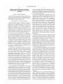
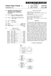
FIG. 6 is an exemplary schematic block diagram of a
portable Wiring fault detection and diagnosis device 400. As
shoWn in FIG. 6, the portable Wiring fault detection and
diagnosis device 400 includes the Wiring fault diagnostic
manager 126 and the Wiring fault detection unit 128, Which
are described in detail above in connection With FIGS. 2 and
3. The device 400 further includes a memory 402, a pro
cessor 404 that is communicatively coupled to the memory
404, a display 406, a keypad 408 and a poWer source 410.
a keypad communicatively coupled to the processor; and
a poWer source that supplies poWer to the portable unit.
10
of measurement blocks.
15
6. The system of claim 5, Wherein the signal sWitching
unit is further adapted to disconnect the signal line of the
protocol bus from a communication circuit.
7. The system of claim 4, Wherein the signal sWitching
unit is responsive to signals sent by the Wiring fault diag
The Wiring diagnostic manager 126 and the Wiring fault
nostic manager.
detection unit 128 function generally as described above
except that Wiring faults are not necessarily reported to a
user interface at the system level. Instead, Wiring fault
information is displayed as graphic and/or textual informa
tion Within the display 406. A user may request particular
4. The system of claim 1, Wherein the Wiring fault
detection unit includes a signal sWitching unit and a plurality
of measurement blocks coupled to the signal sWitching unit.
5. The system of claim 4, Wherein the signal sWitching
unit is adapted to be coupled to the protocol bus and to
couple a signal line of the protocol bus to one of the plurality
8. The system of claim 4, Wherein the plurality of mea
surement blocks includes one of an ohmmeter block, a
25
voltmeter block, a signal generator block, a noise meter
block, a ground fault detector block, and a capacitance meter
block.
9. The system of claim 1, Wherein the type of the Wiring
test sequences, may retrieve information stored in the
memory 404, or may enter or change test parameters, etc.
using the keypad 408. Preferably, but not necessarily, the
fault is one of a short circuit, an open circuit, a ground fault,
an improper termination, an insuf?cient signal strength, a
poWer source 410 includes a battery so that the bus 30 may
be tested Without requiring a local poWer source near each
voltage.
segment that is to be tested. In operation, a ?eld technician
may connect the device 400 to a segment suspected of
having a Wiring fault, or any segment Which needs to be
commissioned, and invokes a desired test sequence.
While the invention has been described With reference to
poor quality ground connection and an improper supply
10. A method of detecting a Wiring fault for use Within a
process control system having a user interface, a protocol
bus, a linking device that enables a controller to communi
35
fault detection unit residing therein, the Wiring fault detec
speci?c examples, Which are intended to be illustrative only
and not to be limiting of the invention, it Will be apparent to
those of ordinary skill in the art that changes, additions or
tion unit including a plurality of measurement blocks and a
signal sWitching unit, the method comprising:
deletions may be made to the disclosed embodiments With
out departing from the spirit and scope of the invention.
What is claimed is:
40
substantially active;
plurality of measurement blocks;
process control system having a plurality of smart ?eld
devices communicatively coupled to a protocol bus, the
45
active;
With the plurality of smart ?eld devices, the linking
device being further operable to automatically detect a
communications problem associated With the protocol
bus While the protocol bus is substantially active, and
Wherein the linking device has a Wiring fault detection
unit and a Wiring fault detection unit residing therein;
the Wiring fault detection unit being adapted to be coupled
sending the measured electrical characteristic to the Wir
ing fault diagnostic manager;
determining a type of the Wiring fault based on the
measured electrical characteristic; and
automatically reporting the type of the Wiring fault to the
user interface.
55
istic associated With the protocol bus While the protocol
bus is substantially active; and
the Wiring fault diagnostic manager being communica
tively coupled to the Wiring fault detection unit and
using the measured electrical characteristic to deter
mine a type of the Wiring fault.
2. The system of claim 1, Wherein the Wiring fault
detection unit and the Wiring fault diagnostic manager reside
Within a portable unit that is adapted to be locally coupled
to the protocol bus.
3. The system of claim 2, Wherein the portable unit
includes:
measuring an electrical characteristic associated With the
protocol bus using the one of the plurality of measure
ment blocks While the protocol bus is substantially
a linking device that enables a controller to communicate
to the protocol bus to measure an electrical character
automatically detecting a communications problem asso
ciated With the protocol bus While the protocol bus is
connecting a signal line of the protocol bus to one of the
1. A system that detects a Wiring fault for use Within a
system comprising:
cate With the plurality of smart ?eld devices, and Wherein the
linking device has a Wiring fault detection unit and a Wiring
65
11. The method of claim 10, Wherein the step of connect
ing the signal line of the protocol bus to the one of the
plurality of measurement blocks includes the step of con
necting the signal line to one of an ohmmeter block, a
voltmeter block, a signal generator block, a noise meter
block, a ground fault detector block, and a capacitance meter
block.
12. The method of claim 10, Wherein the step of connect
ing the signal line of the protocol bus to the one of the
plurality of measurement blocks includes the step of con
necting the signal line to the one of the plurality of mea
surement blocks in response to a signal from the Wiring fault
diagnostic manager.
US 6,912,671 B2
17
18
matically detects a communications problem associated
With the protocol bus While the protocol bus is sub
13. The method of claim 10, wherein the step of measur
ing the electrical characteristic associated With the protocol
bus using the one of the plurality of measurement blocks
stantially active.
includes the step of disconnecting the signal line of the
19. The system of claim 18, Wherein the second routine is
further adapted to cause the Wiring fault detection unit to
disconnect the signal line of the protocol bus from a com
munication circuit.
20. The system of claim 18, Wherein the second routine is
protocol bus from a communication circuit.
14. The method of claim 10, Wherein the step of measur
ing the electrical characteristic associated With the protocol
bus includes the step of measuring one of a resistance, a
capacitance, a signal amplitude, a noise level and a poWer
supply voltage.
further adapted to measure one of a resistance, a
10
15. The method of claim 10, Wherein the step of deter
mining the type of the Wiring fault based on the measured
electrical characteristic includes the step of comparing the
supply voltage.
measured electrical characteristic to a predetermined value
associated With the Wiring fault.
capacitance, a signal amplitude, a noise level and a poWer
15
16. The method of claim 15, Wherein the step of com
paring the measured electrical characteristic to the prede
termined value includes the step of using a predetermined
21. The system of claim 18, Wherein the third routine is
further adapted to compare the measured electrical charac
teristic to a predetermined value associated With the Wiring
fault.
22. The system of claim 21, Wherein the third routine is
further adapted to use a predetermined value associated With
value associated With one of a short circuit, an open circuit,
one of a short circuit, an open circuit, a ground fault, an
a ground fault, an improper termination, an insuf?cient
improper termination, an insuf?cient signal strength, a poor
signal strength, a poor quality ground connection and an
quality ground connection and an improper supply voltage.
improper supply voltage.
23. A system that detects a Wiring fault for use Within a
17. The method of claim 10, Wherein the step of auto
matically reporting the type of the Wiring fault to the user
interface includes the step of sending Wiring fault informa
process control system having a controller and a protocol
bus, the system comprising:
25
tion to the user interface via a controller.
18. A system for detecting a Wiring fault for use Within a
process control system having a user interface, a controller,
a protocol bus, a processor, and a linking device that enables
a controller to communicate With the plurality of smart ?eld
a plurality of measurement blocks communicatively
coupled to the controller and adapted to be coupled to
the protocol bus, Wherein the controller is programmed
to connect one of the plurality of measurement blocks
to the protocol bus to detect the Wiring fault and
Wherein the measurement blocks reside Within a linking
devices, the linking device having a Wiring fault detection
unit and a Wiring fault diagnostic manager therein, the
device, Wherein the linking device enables the control
Wiring fault detection unit including a plurality of measure
ment blocks and a signal sWitching unit, the system com
devices, the linking device being operable to automati
prising:
ler to communicate With a plurality of smart ?eld
cally detect a communications problem associated With
35
the protocol bus While the protocol bus is substantially
active.
a computer readable medium;
a ?rst routine stored on the computer readable medium
24. The system of claim 23, Wherein the plurality of
and adapted to be executed by the processor that causes
the Wiring fault detection unit to connect a signal line
of the protocol bus to one of the plurality of measure
ment blocks;
voltmeter block, a signal generator block, a noise meter
block, a ground fault detector block, and a capacitance meter
block.
measurement blocks includes one of an ohmmeter block, a
40
a second routine stored on the computer readable medium
25. The system of claim 23, Wherein the Wiring fault is
and adapted to be executed by the processor that causes
one of a short circuit, an open circuit, a ground fault, an
the Wiring fault detection unit to measure an electrical 45 improper termination, an insuf?cient signal strength, a poor
quality ground connection and an improper supply voltage.
characteristic associated With the protocol bus using the
26. The system of claim 1, Wherein the automatic detec
one of the plurality of measurement blocks While the
tion of the communications problem occurs during an asyn
chronous communication interval.
protocol bus is substantially active;
a third routine stored on the computer readable medium
27. The method of claim 10, Wherein automatically
detecting the communications problem associated With the
and adapted to be executed by the processor that
determines a type of the Wiring fault based on the
measured electrical characteristic;
a fourth routine stored on the computer readable medium
and adapted to be executed by the processor that
automatically reports the type of the Wiring fault to the
user interface; and
a ?fth routine stored on the computer readable medium
and adapted to be executed by the process that auto
55
protocol bus occurs during an asynchronous communication
interval.
28. The system of claim 18, Wherein the ?fth routine
automatically detects a communications problem associated
With the protocol bus during an asynchronous communica
tion interval.
UNITED STATES PATENT AND TRADEMARK OFFICE
CERTIFICATE OF CORRECTION
Page 1 of l
PATENT NO. : 6,912,671 B2
DATED
: June 28, 2005
INVENTOR(S) : Daniel D. Christensen et a1.
It is certified that error appears in the above-identi?ed patent and that said Letters Patent is
hereby corrected as shown below:
Title page,
Item [73], Assignee, delete “Bisher” and insert -- Fisher --.
Item [56], References Cited, U.S. PATENT DOCUMENTS, insert the following:
-- 5,066,919
6,230,109
6,046,594
5,848,238
4,792,950
5,168,237
5,539,306
3,701,848
5,521,903
6,037,779
ll-l 991
05-2001
04-2000
12-1998
12-1988
12-1992
07-1996
10-1972
05-1996
03-2000
Klassen et a1.
Miskimins et a1.
Mavretic, Anton
Shimomura et a1.
Volk et a1.
Fieau et a1.
Riggio, Jr. Salvatore R.
Joseph W. Dehn
English et a1.
DeWeerdt et a1. --.
Column 12
Line 7, delete “maybe” and insert -- may be --.
Signed and Sealed this
Thirtieth Day of May, 2006
,. Wgaw
JON W. DUDAS
Director ofthe United States Patent and Trademark O?ice
UNITED STATES PATENT AND TRADEMARK OFFICE
CERTIFICATE OF CORRECTION
PATENT NO.
: 6,912,671 B2
Page 1 of 1
APPLICATION NO. : 09/850300
DATED
: June 28, 2005
INVENTOR(S)
: Daniel D. Christensen et al.
It is certified that error appears in the above-identi?ed patent and that said Letters Patent is
hereby corrected as shown below:
In the Claims:
At Column 15, lines 52-53, “a Wiring fault detection unit and a Wiring fault
detection unit” should be -- a Wiring fault detection unit and a diagnostic manager --.
At Column 16, lines 35-36, “a Wiring fault detection unit and a Wiring fault
detection unit” should be -- a Wiring fault detection unit and a diagnostic manager --.
Signed and Sealed this
Twenty-third Day of September, 2008
Mir/git
JON W. DUDAS
Director ofthe United States Patent and Trademark O?ice