1
E5@C/E5@C-T
Error Displays (Troubleshooting)
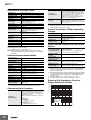
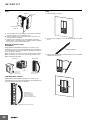
When an error occurs, the No. 1 display or No. 2 display shows the error code.
Take necessary measure according to the error code, referring the following table.
Display
Name
Meaning
The input value exceeded the control
range.*
The input type is not set correctly.
The sensor is disconnected or shortcircuited.
The sensor is not wired correctly.
The sensor is not wired.
s.err
Input error
[[[[
Display
range
exceeded
]]]]
* Control Range
Temperature resistance
thermometer or thermocouple input:
SP Lower Limit - 20°C to SP Upper
Limit + 20°C
(SP Lower Limit - 40°F to SP Upper
Limit + 40°F)
ESIB input:
Same as specified input range.
Analog input:
Scaling range -5% to 105%
This is not an error. It
is displayed when the
Below -1,999 control range is wider
than the display
range and the PV
exceeds the display
range. The PV is
displayed for the
range that is given on
Above 9,999 the left (the number
without the decimal
point).
e333
A/D
converter
error
There is an error in the internal
circuits.
e111
Memory
error
There is an error in the internal
memory operation.
Action
Operation
After the error occurs and it is
Check the wiring for input to be sure displayed, the alarm output will
it is wired correctly, not broken, and operate as if the upper limit was
not shorted. Also check the input
exceeded.
type.
It will also operate as if transfer
If there are no problems in the wiring output exceeded the upper limit.
or input type settings, cycle the
If an input error is assigned to a
power supply.
control output or auxiliary output, the
If the display remains the same,
output will turn ON when the input
replace the Digital Temperature
error occurs.
Controller.
The error message will appear in the
If the display is restored to normal, display for the PV.
then the probable cause is external
noise affecting the control system.
Note: 1. The heating and cooling
Check for external noise.
control outputs will turn
OFF.
Note: For a temperature resistance
2. When the manual MV, MV
thermometer, the input is
at stop, MV at reset, or MV
considered disconnected if
at error is set, the control
the A, B, or B’ line is broken.
output is determined by the
set value.
-
First, cycle the power supply.
If the display remains the same, the
controller must be repaired.
If the display is restored to normal,
then a probable cause can be
external noise affecting the control
system. Check for external noise.
First, cycle the power supply.
If the display remains the same, the
controller must be repaired.
If the display is restored to normal,
then a probable cause can be
external noise affecting the control
system. Check for external noise.
ffff
Overcurrent
This error is displayed when the peak
current exceeds 55.0 A.
-
ct1
ct2
lcr1
lcr2
HB or HS
alarm
If there is a HB or HS alarm, the No.
1 display will flash in the relevant
setting level.
-
----
"----" will be displayed for the Valve
Opening Monitor parameter if any of
the following error occurs.
• Motor calibration has not been
Potentiometer
performed.
Input Error
•
The wiring of the potentiometer is
(Positionincorrect or broken.
proportional
Models Only) • The potentiometer input value is
incorrect (e.g., the input is out of
range or the potentiometer has
failed).
Check for the above errors.
Control continues and operation is
normal.
The value will appear in the display
for the PV.
Refer to the E5@C Digital
Temperature Controllers User’s
Manual (Cat. No. H174) or the
E5@C-T Digital Temperature
Controllers Programmable Type
User’s Manual (Cat. No. H185) for
information on the
controllable range.
The control outputs, auxiliary
outputs, and transfer outputs turn
OFF. (A current output will be approx.
0 mA and a linear voltage output will
be approx. 0V.)
The control outputs, auxiliary
outputs, and transfer outputs turn
OFF. (A current output will be approx.
0 mA and a linear voltage output will
be approx. 0V.)
Control continues and operation is
normal.
The error message will appear for the
following displays.
Heater Current Value 1 Monitor
Heater Current Value 2 Monitor
Leakage Current Value 1 Monitor
Leakage Current Value 2 Monitor
The No. 1 display for the following
parameter flashes in Operation Level
or Adjustment Level.
Heater Current Value 1 Monitor
Heater Current Value 2 Monitor
Leakage Current Value 1 Monitor
Leakage Current Value 2 Monitor
However, control continues and
operation is normal.
Close control: The control output is
OFF or the value that is set for the
MV at PV Error parameter is output.
Floating control: Operation will be
normal.
21