1
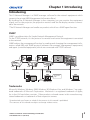
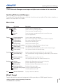
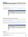
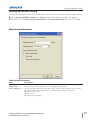
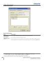
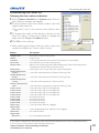
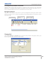
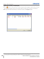
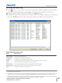
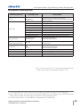
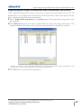
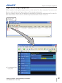
LW555
USER MANUAL-PJ Network Manager
020-000250-01
PJ Network Manager for Windows
020-000250-01
This is the manual for the PJ Network Manager software.
This software is Windows-compliant, but non-Mac-compliant.
Read this manual thoroughly to operate the PJ Network Manager software.
First, read the user's manual of the projector to understand the basic operation of the
projector and the safety instructions.
The safety instructions in the user's manuals should be followed strictly.
-8User Manual
SNMP Manager Software
Contents
Contents ..................................................................................2
Chapter 1 Introducing ..........................................................3
Introducing ......................................................................................................................................................3
SNMP ...................................................................................................................................................................3
Trademarks.......................................................................................................................................................3
Operating Environment ...........................................................................................................................4
Chapter 2 Set up ....................................................................5
PJ Network Manager installation........................................................................................................6
PJ Network Manager un-installation ................................................................................................6
Chapter 3 Basic Operation ...................................................7
Launching and quitting PJ Network Manager...........................................................................8
Name of status window...........................................................................................................................8
Quitting PJ Network Manager..............................................................................................................9
Menu tree .........................................................................................................................................................9
What's Target ..................................................................................................................................................9
Name of the button on the tool bar .............................................................................................10
Icon display for the target....................................................................................................................10
Addition of the target ............................................................................................................................11
Editing the target ......................................................................................................................................11
Deletion of the target.............................................................................................................................11
Setting up the warning value ...........................................................................................................12
Starting target monitoring..................................................................................................................12
When happens the alert on the target .......................................................................................13
When happens the trap event on the target ..........................................................................13
What's Trap....................................................................................................................................................13
Stopping monitoring the target......................................................................................................14
Displaying all the status information of the target ..............................................................14
Setting the target group ......................................................................................................................14
Setting up the password of Telnet .................................................................................................15
Setting commands batch processing for multiple targets .............................................15
Setting timer for targets........................................................................................................................16
Setting up default setting....................................................................................................................17
Customizing the status list ..................................................................................................................19
Viewing the alert information ...........................................................................................................22
Viewing the event log............................................................................................................................23
Description of Event, Type, Warning column, Warning value ......................................24
About event treatment .........................................................................................................................26
Viewing the command history.........................................................................................................27
Storing the management file ............................................................................................................28
Information saved to the registry ..................................................................................................28
Registering the target information from the defined file at once ..............................29
Format of the defined file ....................................................................................................................30
Example of the defined file .................................................................................................................30
Login to the target equipment ........................................................................................................31
2
-86TFS.BOVBMPJ Network Manager for Windows
020-000250-01 Rev.1 (05-2010)
Chapter 1 Introducing
Introducing
This PJ Network Manager is a SNMP manager software for the network equipment which
supports the private MIB (Management Information Base).
By installing the PJ Network Manager to the computer, you can monitor the equipment
simply such as the projector, the projection monitor and the flat display monitor connected to the network.
* The PJ Network Manager can handle our products which has a SNMP agent function.
SNMP
SNMP is an abbreviation for Simple Network Management Protocol.
On the TCP/IP network, it is the protocol to monitor and control the equipment connected
to the network.
SNMP realizes the management function by reading and changing the management information called MIB with SNMP protocol between the manager (management equipment)
and agent (controlled equipment) which are connected with TCP/IP network.
PJ1
PJ4
PJ3
PJ2
Trap
PC6
PC5
PC4
You received
a trap.
Trap
SNMP Manager
Trademarks
Microsoft, Windows, Windows 2000, Windows XP, Windows Vista, and Windows 7 are registered trademarks of Microsoft Corporation. Macintosh is a registered trademark of Apple,
Inc. in the USA and other countries. Other products or brand names in this manual are registered trademarks or trademarks of their respective owners.
* Unauthorized use of a part or whole of the contents in this manual is prohibited.
* The contents of this manual are subject to change without notice.
-86TFS.BOVBMPJ Network Manager for Windows
020-000250-01 Rev.1 (05-2010)
3
Chapter 1 Introducing
Operating Environment
Item
Minimum
Recommended
CPU
Pentium III 400MHz or higher
Pentium 4 2.0GHz or higher for Windows XP
Pentium 4 3.0GHz or higher for Windows Vista
and Windows 7
Memory
128MB or higher
256MB or higher for Windows XP
1GB or higher for Windows Vista and Windows 7
HDD
More than 20MB of free disk space
Screen
resolution
SVGA (16 colors or more)
XGA True color or more
LAN
10Mbps or more
100Mbps or more
OS
Windows 2000
Windows XP
Windows 7
Windows XP Professional
Windows Vista (32bit version)
Windows 7 (32bit version)
Limited condition
The number of agents monitored is up to 200.
Expression/Abbreviation
The OS of the computer and the Web browser described in this manual is Windows XP
Professional and Internet Explorer 6.0. In case of another OS or Web browser, some instruction procedures may differ from the actual operation depending on your computer environment.
Use of this manual
This manual does not provide the description of basic operation and functions for computer, web browser, projector and network. For instructions about each piece of equipment or
application software, please refer to the respective manual.
4
-86TFS.BOVBMPJ Network Manager for Windows
020-000250-01
Rev.1 (05-2010)
2
Chapter 2
Set up
-86TFS.BOVBMPJ
PJ
Network Manager for Network
WindowsManager for Windows
020-000250-01 Rev.1 (05-2010)
5
Chapter 2 Set up
PJ Network Manager installation
1 Set the supplied CD-ROM into the CD-ROM
drive of your computer. Double click SetupTool.
exe icon in the "PJ Network Manager" folder in
the CD-ROM.
2 Select "[English [United States]" from the pull-
down menu on the "Choose Setup Language"
window and click OK button to start installing
and then follow the installation wizards.
As the "Software License Agreement" will
appear, read contents carefully and click Yes
button if you agree with the license agreement to proceed with installing.
Note:
To install the software into the computer with Windows 2000, Windows XP, Windows
Vista, or Windows 7 you should logon as administrator. Before installation, make sure
that the other applications are closed, otherwise proper installation cannot be made.
PJ Network Manager un-installation
To remove the PJ Network Manager software from your computer, perform it with "Add
& Remove Programs" on the control panel. (In case of Windows Vista or Windows 7, use
"Programs and Features" from the control panel.)
6
-86TFS.BOVBMPJ Network Manager for Windows
020-000250-01 Rev.1 (05-2010)
3
Chapter 3
Basic Operation
-86TFS.BOVBMPJ
PJ
Network Manager for Network
WindowsManager for Windows
020-000250-01 Rev.1 (05-2010)
7
Chapter 3 Basic Operation
Launching and quitting PJ Network Manager
To launch PJ Network Manager, take one of the following.
- Select "PJ Network Manager" from the menu "Start" - "All programs".
- Double click a management file*1.
Name of status window
Tool bar
Menu
Status column
Target
Polling times indication
Status bar
Event indication
Status list
* With double clicking the target name, the web browser is launching and
displays login window of the target.(p.31)
Items
Description
Menu..................................... Executes a command with menu selection
Tool bar ............................... Executes a command assigned to a button.
Target ................................... Network equipment for monitoring.
Status bar........................... Indicates the status of PJ Network Manager and explaining the command selected
with cursor.
Status list............................ Indicates the status of targets monitoring.
When some errors are detected, the target name, icon and error items are indicated
with red.
Status column ................ Column of status list.
Polling times indication ......... Indicates the times of polling during the monitoring.
Event indication ............ Indicates the event (ALERT, TRAP, SYSERR) when the event happened.
*1 The file in which the Monitor target information and event log information are stored. Refer to item
"Storing the management file" (p.28) for further details.
8
-86TFS.BOVBMPJ Network Manager for Windows
020-000250-01 Rev.1 (05-2010)
Quitting PJ Network Manager
[Note]
* The PJ Network Manager cannot open multiple status windows at the same time.
Quitting PJ Network Manager
To quit the PJ Network Manager, click the close box on top right of the status window, or
select "Exit" from the "File" menu
Menu tree
Menu
Sub menu
Operation
File
New
Open
Save
Save As
Exit
Creates a new management file.
Opens an existing management file.
Saves the active management file.
Saves the active management file with a new file name.
Quits the application.
Target
Target monitoring
Target addition
Target editing
Target deletion
Group setting
Warning value setting
Telnet setting
Commands batch processing
Timer setting
Starts or stops target monitoring.
Adds a new target. Target information window will appear.
Edits selected target information.
Deletes the selected target.
Groups the selected targets.
Sets up the warning value of the selected target.
Sets up the password of telnet.
Sets commands batch processing for multiple selected targets.
Sets up the timer for the selected target.
System
Target batch registration
System default setting
Column selection
Font setting
Imports target information defined with the external file.
Sets up the default setting (monitoring information, e-mail information).
Selects display items on the status list.
Sets up display font type and size on the status list.
Display
Update
Target display
Alert display
Event log display
Command history display
Tool bar
Updates the information on the status list display.
Displays selected target information.
Displays all of alert information on the status list.
Displays all the event logs.
Displays all of command history.
Switches tool bar on or off.
Help
Version information
Displays version of software.
What's Target
Target indicates the network equipment which provides an SNMP agent function .
-86TFS.BOVBMPJ Network Manager for Windows
020-000250-01 Rev.1 (05-2010)
9
Chapter 3 Basic Operation
Name of the button on the tool bar
The following commands are assigned to the buttons on the tool bar.
New
Save
Open
Button
Target display
Target monitoring
Start/Stop
Event log display
Alert display
Command history display
Operation
New.................................................. Creates a new management file.
Open ............................................... Opens an existing management file.
Save ................................................. Saves the active management file.
Target monitoring ................. Starts or stops target monitoring.
Target display ........................... Displays selected target information.
Alert display ............................... Displays all of alert information on the status list.
Event log display .................... Displays all the event logs.
Command history display .. Displays all of the command history.
To switch the tool bar display on or off, select "Tool bar" from "Display" menu.
Icon display for the target
Displays icon according to the target condition.
Icon
Condition
Flat display type Projector type
Normal
Abnormal condition (One of the abnormalities, Alert, Trap or System
error is happening on the target.)
Connection error (Target has been disconnected from the network)
Acquisition error (Target has been disconnected from the network, or
does not provide SNMP function.)
Unknown (Target monitoring is not operating)
10
-86TFS.BOVBMPJ Network Manager for Windows
020-000250-01 Rev.1 (05-2010)
Addition of the target
Addition of the target
1 Select Target Addition from Target menu. The target
information registering window appears.
Items
Description
Name ......................... Enter a management name of the target
equipment.
IP address ............... Enter IP address of the target equipment.
Community ........... Enter a community name in the network.
Default name is "public".
System information ..... Displays information set on the network
equipment
2 Enter target setup information and click Update button.
The information set on the target equipment are displayed on the system information items.
When the target equipment is not operating, or it is not the
monitoring equipment, the error dialog "Cannot obtain information" will appear.
3 Click OK to close the window. Repeat the above steps to register for other equipment
which is to be managed.
Editing the target
1 Select a target name to edit on the status list with right click.
2 Select Target editing on the popup menu. The target information window will appear
and edit the contents, then click OK button.
The system information cannot be edited.
Target editing can be executed by selecting Target editing from Target menu.
Deletion of the target
1 Select a target name to delete on the status list with right click.
2 Select Target deletion on the popup menu. The confirmation dialog will appear and
click Yes button to execute deleting.
Target deletion can be executed by selecting Target deletion from Target menu.
It cannot perform the target addition, editing and deletion during the target monitoring.
Up to 200 targets can be registered.
Up to 255 characters can be used for target name and community.
-86TFS.BOVBMPJ Network Manager for Windows
020-000250-01 Rev.1 (05-2010)
11
Chapter 3 Basic Operation
Setting up the warning value
PJ Network Manager provides a function to
display the alert when the use time of the setting item reaches a specified setting time. The
available setting items (use time) are depending on the target equipment.
1 Select a target on the status list with right click.
When setting multiple targets together, select
targets with pressing "Shift" or "Control" key.
2 Select Warning value setting on the popup
menu. The setting window will appear as
the right figure.
3 Check Warning time check box. The setting
items are activated. Select a setting item and click
Edit button. Another setting window appears.
4 Enter the threshold value of selected item and
then click OK button. The setting window will disappear.
5 Set up warning value for remaining items if available and then click OK button. The setting window will disappear.
(Example of the set up window)
To disable the warning value, clear Warning time check box.
When selecting multiple targets, the value set to the lowest target on the status list is displayed as
the current setting time. Up to 99,999 hours can be set for the use time. The warning value is stored
in the management file.
Starting target monitoring
1 Click button on the tool bar to start monitoring the target.
2 PJ Network Manager starts polling the target in a sequential from the top of the status
list and displays the results on the status list.
12
-86TFS.BOVBMPJ Network Manager for Windows
020-000250-01 Rev.1 (05-2010)
When happens the alert on the target
When happens the alert on the target
If the abnormality or connection error happens on the target, PJ Network Manager indicates target name, icon and status column item with red color to let you know the abnormality.
When PJ Network Manager cannot acquire the MIB information of the target equipment, it indicates as Connection Error.
The interval of target monitoring is according to the setting of Monitoring interval on System
default setting from System menu. (p.17)
When happens the trap event on the target
During the target monitoring, if the predefined event (trap) happens on the target equipment, the target sends the trap information to PJ Network Manager. This trap information is
displayed on the status list immediately.
The notification of the trap information is set up in the SNMP setting items of the target
equipment. Projector has items such as "When PJ lamp is off", "When the life span of lamp
is reached", "When internal PJ power circuit is failed" etc. For further trap information, refer
to SNMP trap information in the separated network owner's manual.
What's Trap
Trap is the event predefined by the SNMP agent. If the predefined event ( "When PJ lamp is
off", "When internal PJ power circuit is failed" etc. ) happens, target sends trap information
to the SNMP manager.
-86TFS.BOVBMPJ Network Manager for Windows
020-000250-01 Rev.1 (05-2010)
13
Chapter 3 Basic Operation
Stopping monitoring the target
To stop monitoring the target, click
button again on the tool bar.
Displaying all the status information of the target
button on the tool bar. The following status window appears
Select a target and click
and displays all the available status information of the target.
The target name and item which have an
abnormality or connection error happening are indicated with red.
When PJ Network Manager cannot
acquire the value of column information,
"---" is displayed.
The above procedure can perform by selecting Target display from Display menu.
Setting the target group
The target group can be set up by the procedure below. When you set a command in the
same group, you set it.
1 Select targets which you want to set from the status list. Select Group setting from
Target menu, the dialog box will appear as the below figure.
2 Select a group, and then click OK button.
"---" will not set the group.
The projectors setting different network passwords cannot be set to the same group. It is
necessary for the projectors in the same group to set to the same password.
14
-86TFS.BOVBMPJ Network Manager for Windows
020-000250-01 Rev.1 (05-2010)
Setting up the password of Telnet
Setting up the password of Telnet
The password of telnet can be set up by the procedure below. It is necessary to make a
password, same as the network password.
1 Select a target which you want to set up the password of telnet from the status list. You
can select multiple targets.
2 Select Telnet setting from Target menu, Telnet setting dialog box will appear as the
below figure. Set a password and click OK button. When multiple targets are selected, all
the selected targets are set as the same password.
The initial setting is "0000".
Setting commands batch processing for multiple targets
The commands batch processing for multiple targets can be set up by the procedure
below.
1 Select a target belonging to the batch processing group which you want to set, and
select Commands batch processing from Target menu. Commands batch processing
dialog box will appear as the below figure.
2 Select a command which you want to set, click Edit button. Parameter editing dialog box will appear. Select a parameter, and then click OK button. The check box of
Commands batch processing dialog box will be checked.
3 Click OK button. The commands are carried out to all the targets of the same group.
The commands also work for the target which is not set to a group.
-86TFS.BOVBMPJ Network Manager for Windows
020-000250-01 Rev.1 (05-2010)
15
Chapter 3 Basic Operation
Commands batch processing : Available Command
Items
Description
Power ON/OFF .........................Sets up the Power ON or Power OFF.
Input,Source .............................. Sets up the Input and Source. Selects Input and Source.
Screen .......................................Sets up the screen size. Resizes the picture screen.
Background ............................... Sets up the background. Selects the background screen for when no input signal is
detected.
Display ........................................ Sets up the Display. Decides whether to display On-Screen Displays or not.
Shutter(No show) .................... Sets up the Shutter (No show). Sets black out the image.
Lamp control ............................. Sets up the Lamp control. Changes brightness of the screen.
Fan control ................................. Sets up the Fan control. Chooses the running speed of cooling fans.
Setting timer for targets
The timer information for targets can be set up by the procedure below.
1 Choose a target which you want to set the timer.
2 Select Timer setting from Target menu. Timer selection dialog box will appear as the
below figure. Check in a check box of an event to carry out.
3 When you want to add events, click Add button. Input timer informations in Timer setting dialog box, and click OK button.
4 Click OK button of Timer selection dialog box, timers are set to the selected target.
When selecting multiple targets, timers are set to all the selected targets.
Timer
Items
Description
Execution date .........................Sets up the Timer execution date. (everyday or a day)
Execution time.......................... Sets up the Timer execution time. (hh:mm:ss)
Action .......................................Sets up the events.
16
-86TFS.BOVBMPJ Network Manager for Windows
020-000250-01 Rev.1 (05-2010)
Setting up default setting
Setting up default setting
The monitoring information and e-mail information can be set up by the procedure below.
1 Select System default setting from System menu. The setting window will appear.
2 Switch by clicking Monitoring information or E-mail information tab for each setting.
Monitoring information
Monitoring information
Items
Description
Monitoring interval ................Sets up the interval of the polling in minute unit. (1 to 99 minutes can be set)
Temperature unit ..................... Sets up the display temperature unit Centigrade or Fahrenheit.
Event reception process..........Sets up the treatment when the event (ALERT, TRAP, SYSERR) happens on the target.
For further information, refer to the item "About event treatment" (p.26).
P Sound warning alarm
P Send e-mail
P Display warning dialog
-86TFS.BOVBMPJ Network Manager for Windows
020-000250-01 Rev.1 (05-2010)
17
Chapter 3 Basic Operation
E-mail information
E-mail information
Items
Description
SMTP server .....................Sets up the IP address of SMTP mail server or server host name.
Administrator's
mail address...................... Sets up the e-mail address of administrator
Destination mail
address ................................Sets up the destination mail address when the event (ALERT, TRAP, SYSERR) happens
on the target. The mail address entering window appears when clicking Add button.
If Send e-mail check box of Event reception process on Monitoring information is un-checked,
the alert e-mail will not be sent even if you set up the e-mail address.
Up to 10 addresses can be set up for the destination mail address.
18
For the contents of the mail, refer to item "About event treatment" (p.26).
-86TFS.BOVBMPJ Network Manager for Windows
020-000250-01 Rev.1 (05-2010)
Customizing the status list
Customizing the status list
Changing the status column indication
1 Select Column selection from System menu. The column selection window will appear.
2 On the window, check the column name to be indicated on the status list.
The mark [*] next to the column name indicates alert
item.
3 To change the order of the display column on the
status list, select a column you intend to change the
order and click To up or To down button.
4 Click OK to close setting.
Specifies column width
When specifying the column width by numeric value, enter
number (0 to 9999) onto "Column width" text box.
Column
Description
*Target name ............................Name of the network equipment
*Group ...........................................Group name
*Connect ......................................Status of connection to the network (Connected, Un-connected)
*Drive time .................................Accumulated use time of the equipment
*Power status............................Power status of the equipment (Normal(Power-on), Normal(Standby), Power
Management, Power failure, lamp failure, etc.)
*Input status..............................Input signal status (Signal, No signal, Signal interrupted)
*Inside Temperature
A status ....................................Status of inside temperature A (Normal, Warning, Error)
*Inside Temperature
B status ....................................Status of inside temperature B (Normal, Warning, Error)
*Inside Temperature
C status ....................................Status of inside temperature C (Normal, Error)
*External Temperature
status.........................................Status of external temperature (Normal, Warning, Error)
*Lamp1 status ..........................Status of Lamp1 (Off, On, Error, Replace)
*Lamp2 status ..........................Status of Lamp2 (Off, On, Error, Replace)
*Lamp3 status ..........................Status of Lamp3 (Off, On, Error, Replace)
*Lamp4 status ..........................Status of Lamp4 (Off, On, Error, Replace)
*Lamp1 time..............................Used time of Lamp1
*Lamp2 time..............................Used time of Lamp2
*Lamp3 time..............................Used time of Lamp3
*Lamp4 time..............................Used time of Lamp4
*Filter status...............................Status of airfilter (Normal, Clogged)
*Option Box
filter status ............................Status of option box filter (Normal, Error, Clogged)
*Filter time ..................................Use time of airfilter
*Option Box
filter time................................Use time of option box filter
The values in parentheses are typical value and they differ depending on the connected equipment.
The [*] next to the column name indicates alert items.
-86TFS.BOVBMPJ Network Manager for Windows
020-000250-01 Rev.1 (05-2010)
19
Chapter 3 Basic Operation
Column
Description
*Error info. ...................................Error information (Not available for the projector)
IP address ....................................IP address of the network equipment
Community ................................Community name of the network equipment (public)
Introduction date*1...............Date of the network equipment installed
Timer ...............................................Timer information
Product info. ..............................Name of the network equipment
System name ............................System name of the network equipment (Proj_05)
Contact ..........................................Contact information of the network equipment
Location ........................................Installed location of the network equipment
Input signal ................................Information of the input mode (Input1, Input2, etc.)
Input select ................................Information of the input source (RGB, VIDEO, S-VIDEO, NETWORK, etc.)
Network status.........................Condition of the network mode (Off line, Network Viewer, Network Capture)
Audio system ............................Displays audio system mode (NORMAL, PERSONAL, MUSIC, TALK)
Volume ..........................................Sound Volume of the network equipment
Treble ..............................................Sound treble of the network equipment
Bass ..................................................Sound bass of the network equipment
Balance ..........................................Sound balance of the network equipment
Mute ................................................Sound mute status of the network equipment (ON, OFF)
Power management ............Power management status of the network equipment (OFF, READY, SHUTDOWN)
Monitor out ................................Monitor out status of the network equipment (ON, OFF)
Shutter ...........................................Shutter status of the network equipment (OFF, High-Contrast, Normal)
Shutter management .........Shutter management status of the network equipment (Shutdown)
Fan control ..................................Fan control status of the network equipment (Normal, Maximum, OFF, On1, etc. )
Inside Temperature A ..........Displays inside temperature A of the equipment (in Centigrade or Fahrenheit)
Inside Temperature B ..........Displays inside temperature B of the equipment (in Centigrade or Fahrenheit)
Inside Temperature C ..........Displays inside temperature C of the equipment (in Centigrade or Fahrenheit)
External Temperature .........Displays external temperature of the equipment (in Centigrade or Fahrenheit)
Lamp mode................................Displays lamp mode (1: 1-lamp mode, 2: 2-lamp mode, 4: 4-lamp mode, etc.)
Lamp control.............................Displays lamp control mode (Auto, Normal, Eco, etc.)
Model name ..............................Model name of the network equipment
*1 Set up the installed date when the PJ Network Manager is newly introduced.
There are some un-available columns depending on the products. The value of un-available column is displayed in blank or with "---".
20
-86TFS.BOVBMPJ Network Manager for Windows
020-000250-01 Rev.1 (05-2010)
Customizing the status list
To change order or width of the column
Drag the status column name you want to change the order and move it on a new place
and drop it. To change column width, set a mouse cursor onto the right edge of the column to change, drag the mouse on it and adjust the column width.
Sorting the status list
The order of the targets on the status list can be changed by clicking the column name
which you want to sort. It switches ascending or descending order by clicking the column
name each time.
Sort by clicking
Drag to move
column
Drag to change
column width
Changing font
Select Font setting from System menu. The font setup window will appear. Select your
desired type face, style and size on the window.
Customized font property is applied to all the windows of the setting.
-86TFS.BOVBMPJ Network Manager for Windows
020-000250-01 Rev.1 (05-2010)
21
Chapter 3 Basic Operation
Viewing the alert information
1 Click
button on the tool bar. The alert display window appears and the alert information of all the targets which are having an alert is listed on this window as the below.
2 To export the alert information as text file (CSV file), click Export button.
Column width can be changed with dragging the right edge of the column. The column order can
be changed with drag and drop the column. Column can not be deleted.
22
-86TFS.BOVBMPJ Network Manager for Windows
020-000250-01 Rev.1 (05-2010)
Viewing the event log
Viewing the event log
1 Click
button on the tool bar. The event log display window appears and the events
which have been happened on the targets are listed on this window as the below.
2 To export these events as text file (CSV file), click Export button.
3 To delete the event log, select the accrual date item you intend to delete by clicking and
then click Delete button. On the confirmation dialog, click Yes to execute deletion.
Event log information items
Items
Description
Accrual date ......... Accrual date of the event
Target name ......... Name of the network equipment
IP address............... IP address of the network equipment
Event ......................... Type of the Event (ALERT, TRAP, SYSERR ) (See table on the next page)
Type ........................... Type of the Event (See table on the next page)
Warning column.......... Warning column of the Event (See table on the next page)
Warning value .... Warning value of the Event (See table on the next page)
Unit............................. Displays unit of the warning value.
The listed items are fixed.
The order of the event log list can be changed temporarily by clicking the column name which you
want to sort. It switches ascending or descending order by clicking the column name each time.
Column width can be changed by dragging the right edge of the column. The column order can
be changed with drag and drop the column. Column cannot be deleted.
-86TFS.BOVBMPJ Network Manager for Windows
020-000250-01 Rev.1 (05-2010)
23
Chapter 3 Basic Operation
Description of Event, Type, Warning column, Warning value
Event
ALERT
Type
ON : Abnormality has
happened
OFF : Abnormality has been
cleared
Warning Column
Warning Value
Connect
Un-connected
Connected
Acquisition error
Power status
PowerFailure
TemperatureError
Normal (AfterTempError)
RS232CFailure
Power management
Shutter management
LampFailure
Input status
SignalsInterrupted
SignalsInputted
Description
Inside Temperature status (A to
C)
Abnormal
External Temperature status
Failure
Lamp status (1 to 4)
Replace
Lamp time (1 to 4)
(setting time)
Filter status
Clogged
Filter time
(setting time)
LampFailure
Failure
* Refer to the
next page
Lamp status (1 to 4)
TRAP
LampReplace
Replace
PowerOFF
PowreFailure
PowerManagement
ShutterManagement
Power status
Normal(Standby)
Normal(OnCoolingDown)
PowerFailure
Power management
ShutterManagement
ShutterManagement(OnCoolingDown)
TemperatureError
Inside Temperature status (A to
C)
Abnormal
External Temperature status
SignalIsInterrupted
Input status
LampReplacementTime
Lamp time (1-4)
(lamp time)
FilterReplacementTime
Filter time
(filter time)
CloggedFilterWarning
Filter status
Clogged
AutoPlayError
n/a
Error
n/a *1
n/a *1
Transfer
SYSERR *Mail
*MemoryError
24
SignalIsInterrupted
*1 When PJ Network Manager could not send mail or acquire the memory, no message is displayed in
"Warning column" and "Warning value".
For further details of each warning column and value, refer to the next page.
-86TFS.BOVBMPJ Network Manager for Windows
020-000250-01 Rev.1 (05-2010)
Description of Event, Type, Warning column, Warning value
Description of warning value
Warning Column
Warning Value
Description
Connect
Un-connected
Connected *
Acquisition error
Power status
Power failure
TemperatureError
Normal (AfterTempError)
RS232CFailure
Power management
Shutter management
LampFailure
Normal(Standby) *
Normal(OnCoolingDown) *
Projector has been disconnected from the network
Projector has been connected to the network
PJ Network Manager could not acquire the MIB information
from the equipment
Projector turned off due to the power failure of the projector
The projector turned off due to temperature error occurred
Normal after temperature error occurred
The RS-232C communication error occurred
The power management function turned projector lamp off
The shutter management function turned projector lamp off
The lamp failure occurred
Projector turned into standby normally
On cooling down normally due to projector turned off
Input signal status
SignalsInterrupted
SignalsInputted *
The signal was interrupted
The signal was inputted again
Inside Temperature status (A to
C)
Abnormal
External Temperature status
Lamp status
ON *
Failure
Replace
Lamp time
Filter status
Filter time
(Auto play error)
(lamp time)
Clogged
(filter time)
Error
The projector turned off when the temperature was
abnormally high
When the lamp is on
When the lamp failed to ignite.
It reached lamp replacing time.
It reached user setting lamp replacing time
Filter has been clogged
It reached user setting filter time
The error occurred during the auto image display
The warning value with "*" in the above table shows the
event when the alert has cleared, alert type is "OFF".
The column order and width of the event log window are saved to the registry of the computer.
Up to 1000 of events can be stored. If it exceeds 1000 events, the oldest event is deleted and the
latest event is added. The event log can be saved to the management file.
This Warning column is not available for some projector's model types.
-86TFS.BOVBMPJ Network Manager for Windows
020-000250-01 Rev.1 (05-2010)
25
Chapter 3 Basic Operation
About event treatment
If the PJ Network Manager receives an event, it executes following event treatment items
which are selected in the system default setting.
P Sound warning alarm
P Send e-mail
P Display warning dialog
Sound warning alarm
If the PJ Network Manager receives an event, the computer beeps an alarm sound. The
alarm sound is depending on your computer sound setting.
The alarm sound is not made when your computer does not provide any speaker or the sound volume is muted.
Send e-mail
Following example message is sent to the e-mail address you set up as the destination
mail address.
From: Test1<[email protected]> (management
file name)
Date : 2004/10/29 21:30
To : [email protected]
Subject : Alert message
---------------------------------------------------------Alert has occurred
* Accrual date : 2004/10/29 21:13:42
* Target name : Proj_10
* IP address : 192.168.1.101
* Event : ALERT
* Type : ON
* Warning column : Power status
* Warning value : Power failure
For the further information of event, type, warning column and warning value, see the item
"Viewing the event log" (p.23).
The setting of event treatment, refer to item "Setting up default setting" (p.17).
Notes on using Windows XP Service Pack 2 (SP2) / Windows Vista / Windows 7
Windows Firewall is turned on by default in Windows XP SP2, Windows Vista, and Windows 7. Due
to this Windows Firewall, the send e-mail function is not available. When using this mail function, you need to cancel the block for PJ Network Manager application. For the further details of
Windows Firewall, see Windows help on your computer.
26
-86TFS.BOVBMPJ Network Manager for Windows
020-000250-01 Rev.1 (05-2010)
About event treatment
Display warning dialog
Following dialog window appears on the screen if event occurs.
Viewing the command history
1 Click
button on the tool bar. Command history window appears and the command
history is listed on the window as shown below.
2 To export the command history as text file (CSV file), click Export button.
3 To delete the command history, select the item of Executed date/time which you want
to delete, and then click Delete button. On the confirmation dialog box, click Yes button
to execute deletion.
Command history
Items
Description
Executed date/time .... Executed date and time of the command
Target name ......... Name of the network equipment
IP address............... IP address of the network equipment
Command.............. Type of the Command
Detailed data ....... Contents of the Command
Result ........................ Results of the Command
The listed items are fixed.
Column width can be changed by dragging the right edge of the column. The column order can
be changed with drag and drop the column. Column cannot be deleted.
Up to 1000 of events can be stored. If it exceeds 1000 events, the oldest event is deleted and the
latest event is added.
-86TFS.BOVBMPJ Network Manager for Windows
020-000250-01 Rev.1 (05-2010)
27
Chapter 3 Basic Operation
Storing the management file
When you monitor the network equipment with the PJ Network Manager, you can save
the registered target information, system setting and event log information into the management file with a free file name. It is useful if you manage multiple equipment in the network.
Click
button on the tool bar and save it with free file name. The extension is ".pnm".
The management file contains following information.
Items
Description
Header .................................................Management file section, file version
System default setting .............Default value of the system setting
- Monitoring interval
- Event reception process
- Temperature unit
- E-mail information
Target information .....................Information of the registered target
- Target information (target name, IP address, Community, Introduction date)
- target MIB information
- Warning value set up
Event log information...............Event log information (ALERT, TRAP, SYSERR)
The maximum volume of a management file is required about 1MB. (Number of registrable targets
is 200, number of events is 1000)
Information saved to the registry
Following application setting information is saved to the registry of your computer. So the
setting condition is memorized even after quitting the application.
Items
Description
Status window information ................. Display position and size of the status list window
Status list information ............ Display status column, column width and column order
Event log list information ..... Column width and order of the event log list
Font set up ...................................... Font setting value (Type face, size and style)
28
-86TFS.BOVBMPJ Network Manager for Windows
020-000250-01 Rev.1 (05-2010)
Registering the target information from the defined file at once
Registering the target information from the defined file at once
The PJ Network Manager provides a function to import the target information from the
defined file at once. Prepare the defined file (CSV data format) in which the target information is written along the format shown below.
1 Select Target batch registration from System menu. The target batch registration window appears.
2 Click Reference button and select a defined file to import the target information. The
imported target information will be listed on the target batch registration window.
* If there is an error in the imported defined file, the error information will be indicated on the
Result column. Retry importing after correcting the defined file.
3 Click OK button to execute the registration.
Target batch registration is not available during Target monitoring.
-86TFS.BOVBMPJ Network Manager for Windows
020-000250-01 Rev.1 (05-2010)
29
Chapter 3 Basic Operation
Format of the defined file
The defined file is a CSV data file created by the spreadsheet application and is defined as
follows;
Column
Description (example)
Target name.......... Name of target equipment (Proj_01, Proj_03, PDP_01, etc.)
IP address ............... IP address (192.168.0.1, etc.)
Community ........... Name of SNMP community. Default value of our network products is "public"
Example of the defined file
The table below shows the example of the defined file provided with the target information. Save this file as the CSV file.
Target name
30
IP address
Community
Proj_01
192.168.0.1
public
Proj_02
192.168.0.2
public
Proj_03
192.168.0.3
public
Proj_04
192.168.0.6
public
Proj_05
192.168.0.7
public
PDP_01
192.168.0.8
public
FPD_10
192.168.0.9
public
-86TFS.BOVBMPJ Network Manager for Windows
020-000250-01 Rev.1 (05-2010)
Login to the target equipment
Login to the target equipment
After double clicking the target name on the status list, the computer launches web
browser and displays the login window of the target equipment.
You can control and set up the projector remotely by using the web browser. For the further information of instruction, see the separated network owner's manual.
Login by double clicking
An example of the
login page.
-86TFS.BOVBMPJ Network Manager for Windows
020-000250-01 Rev.1 (05-2010)
31
Americas
USA
Christie Digital Systems USA, Inc.
10550 Camden Drive
Cypress CA 90630
PH: 714-236-8610
FX: 714-503-3375
Customer Service: 1-866-880-4462
[email protected]
Canada
Christie Digital Systems Canada, Inc.
809 Wellington St. N.
Kitchener, Ontario N2G 4Y7
PH: 519-744-8005
FX: 519-749-3321
Customer Service: 1-800-265-2171
[email protected]
Chile
Representative Office
Christie Digital Systems USA, Inc.
Av. Pedro Fontova 7619 of 60
Santiago
PH: 56-2-721 11 75
Mobile: 5699 436 6555
United Kingdom
Branch Office
Christie Digital Systems Canada, Inc.
ViewPoint
200 Ashville Way
Wokingham
Berkshire, U.K.
RG41 2PL
PH: +44 (0) 118 977 8000
FX: +44 (0) 118 977 8100
[email protected]
France
Representative Office
Christie Digital Systems Canada, Inc.
Bâtiment D-Hall 4
Parc Louis Roche
96/114 Avenue Louis Roche
F-92230 Gennevilliers
France
PH: +33 (0)1 41 21 44 04
FX: +33 (0)1 41 21 00 36
[email protected]
Germany
Representative Office
Christie Digital Systems Canada, Inc.
Willicher Damm 129
D-41066
Mönchengladbach
PH: +49 2161 664540
FX: +49 2161 664546
[email protected]
Eastern Europe
Representative Office
Christie Digital Systems Canada, Inc.
Regus Bank Centre
Szabadsag ter 7.
H-1054 Budapest
Hungary
PH: +36 (0)1 47 48 100
FX: +36 (0)1 47 48 452
[email protected]
Middle East
Representative Office
Christie Digital Systems Canada, Inc.
C/O Emirates Group Security
Building,
C Block, Room 207, 208, 209
Airport Free Zone
PO Box 293762
Dubai, UAE
PH: +971 (0) 4 299 7575
FX: +971 (0) 4 299 8077
Spain
Christie Authorized Reseller
Antonio Abad
Polígono Industrial Ventorro Del
Cano
Esquina C/ Aldea del Fresno, 3
3ª Puerta. Izqda
28925 Alcorcón, Madrid
PH: + 34 91 633 9990
FX: + 34 91 633 9991
Italy
Christie Authorized Reseller
Angelo Tacca
Via Garibaldi, 88
20024 Garbagnate Milanese (MI)
PH: +39 02 9902 1161
FX: +39 02 9902 2641
Africa
Representative Office
Christie Digital Systems Canada, Inc.
4 Patricia Road
Gillitts
KwaZulu Natal
3610
Republic of South Africa
PH: +27 (0) 317 671 347
FX: +27 (0) 317 671 347
MB: +27 (0) 823 045 442
Singapore
Branch Office
Christie Digital Systems USA, Inc.
627A Aljunied Road
# 05-02 Biz Tech Centre
Singapore, 389842
PH: +65 6877-8737
FX: +65 6877-8747
[email protected]
China - Beijing
Representative Office
Christie Digital Systems USA, Inc.
7B15, Hanwei Plaza
Guanghua Road
Chaoyang District,
Beijing, 100004
PH: +86 10 6561 0240
FX: +86 10 6561 0546
[email protected]
China - Shanghai
Representative Office
Christie Digital Systems USA, Inc.
Room 1109--1116 Shartex Plaza
No. 88 Zun Yi South Road
Shanghai 200336
PH: +86 21 6278 7708
FX: +86 21 6278 5816
[email protected]
Japan
Representative Office
Christie Digital Systems USA, Inc.
A-bldg., 2nd Floor
Ariake Frontier Building
3-1-25, Ariake, Koto-ku
Tokyo, 135-0063
PH: 81-3-3599-7481
FX: 81-3-3599-7482
[email protected]
South Korea
Representative Office
Christie Digital Systems USA, Inc.
6F, ILSIN Building, 15-15
Yeouido-dong,
Yeongdeungpo-gu, Seoul,
150-872 South Korea
PH:+82 2 702 1601
FX: +82 2 702 1602
India
Representative Office
Christie Digital Systems USA, Inc.
Unit No. 03, Navigator Building
International Technology Park
Whitefield Road
Bangalore 560 066
India
PH: (080) 41468941 – 48
FX: (080) 41468949
Europe, Middle East & Africa
Asia Pacific
PJ Network Manager for Windows
PM-KK8K


![CCM-LX [103-115108-01] QUICK SETUP GUIDE](http://vs1.manualzilla.com/store/data/005977333_1-ac67f3228bf0f13da08c247c088ce509-150x150.png)


![Network Set-up and Operation [LX505/LX605]](http://vs1.manualzilla.com/store/data/005961160_1-7c70f8cf6199dbe368f392203d85e61b-150x150.png)