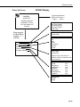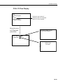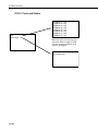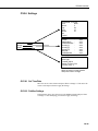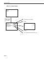
1
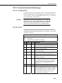
CR3000 Micrologger Overview
Revision: 9/07
C o p y r i g h t © 2 0 0 0 - 2 0 0 7
C a m p b e l l S c i e n t i f i c , I n c .
CR3000 Overview Table of Contents
PDF viewers note: These page numbers refer to the printed version of this document. Use
the Adobe Acrobat® bookmarks tab for links to specific sections.
CR3000 Overview....................................................... OV-1
OV1. Physical Description ......................................................................OV-2
OV1.1 Measurement Inputs ..............................................................OV-3
OV1.1.1 Analog Inputs (SE 1-28, DIFF 1-14) ...........................OV-3
OV1.1.2 Signal Grounds ( )....................................................OV-3
OV1.1.3 Power Grounds (G)......................................................OV-3
OV1.1.4 Ground Lug ( ) .........................................................OV-3
OV1.1.5 Power In (G and 12V)..................................................OV-3
OV1.1.6 Switched 12 Volts (SW-12).........................................OV-3
OV1.1.7 12 Volt Outputs............................................................OV-4
OV1.1.8 5V Output ....................................................................OV-4
OV1.1.9 Switched Voltage Excitation .......................................OV-4
OV1.1.10 Switched Current Excitation......................................OV-4
OV1.1.11 Continuous Analog Outputs.......................................OV-4
OV1.1.12 Digital I/O..................................................................OV-4
OV1.1.13 Pulse Inputs................................................................OV-4
OV1.2 Communication and Data Storage.........................................OV-5
OV1.2.1 Peripheral Port .............................................................OV-5
OV1.2.2 CS I/O ..........................................................................OV-5
OV1.2.3 Computer RS-232 ........................................................OV-6
OV1.3 Power Supply and AC Adapter .............................................OV-7
OV2. Memory and Operating Concepts ..................................................OV-7
OV2.1 Memory .................................................................................OV-7
OV2.2 Programming.........................................................................OV-7
OV2.3 Instruction Execution within the Datalogger.........................OV-8
OV2.3.1 Pipeline Mode..............................................................OV-8
OV2.3.2 Sequential Mode ..........................................................OV-9
OV2.3.3 Slow Sequence Scans ..................................................OV-9
OV2.3.4 Task Priority ................................................................OV-9
OV2.4 Data Tables..........................................................................OV-10
OV2.5 PakBus Communication with the CR3000..........................OV-10
OV2.6 Set up: Device Configuration Utility or Keyboard Display OV-11
OV3. Device Configurator.....................................................................OV-11
OV3.1 Main DevConfig Screen......................................................OV-12
OV3.2 Deployment Tab..................................................................OV-13
OV3.2.1 Datalogger .................................................................OV-13
OV3.2.2 Ports Settings .............................................................OV-14
OV3.2.3 TCP/IP .......................................................................OV-16
OV3.2.4 Advanced ...................................................................OV-17
OV3.3 Logger Control Tab .............................................................OV-18
OV3.4 Data Monitor Tab ................................................................OV-19
OV3.5 Send OS Tab - Downloading an Operating System ............OV-19
OV3.6 Settings Editor Tab..............................................................OV-21
OV4. Quick Start Tutorial .....................................................................OV-23
OV4.1 Software Products for the CR3000......................................OV-23
i
CR3000 Overview Table of Contents
OV4.1.1 Options for Creating CR3000 Programs ................................ OV-24
OV4.2 Connections to the CR3000 ................................................ OV-24
OV4.3 Setting the CR3000 PakBus Address.................................. OV-24
OV4.4 PC200W Software .............................................................. OV-24
OV4.4.1 Creating a CR3000 Program using Short Cut ........... OV-25
OV4.4.2 Configuring the Setup Tab ........................................ OV-30
OV4.4.3 Synchronize the Clocks............................................. OV-30
OV4.4.4 Send the Program...................................................... OV-30
OV4.4.5 Monitor Data Tables ................................................. OV-30
OV4.4.6 Collect Data .............................................................. OV-31
OV4.4.7 View Data ................................................................. OV-32
OV4.5 Programming using the CRBasic Program Editor .............. OV-33
OV5. Keyboard Display........................................................................ OV-34
OV5.1 Data Display ....................................................................... OV-36
OV5.1.1 Real Time Tables ...................................................... OV-37
OV5.1.2 Real Time Custom .................................................... OV-38
OV5.1.3 Final Storage Tables.................................................. OV-39
OV5.2 Run/Stop Program .............................................................. OV-40
OV5.3 File Display ........................................................................ OV-41
OV5.3.1 File: Edit ................................................................... OV-42
OV5.4 PCCard Display .................................................................. OV-43
OV5.5 Ports and Status .................................................................. OV-44
OV5.6 Settings ............................................................................... OV-45
OV5.6.1. Set Time/Date .......................................................... OV-45
OV5.6.2 PakBus Settings ........................................................ OV-45
OV5.6.3 Configure Display..................................................... OV-46
OV6. Specifications .............................................................................. OV-47
Figures
OV1-1. CR3000 Measurement and Control System ............................... OV-1
OV1-2. CR3000 Wiring Panel and Associated Instructions ................... OV-2
Tables
OV1-2. Computer RS-232 Pin-Out......................................................... OV-6
OV2-1. Typical Data Table................................................................... OV-10
ii
CR3000 Overview
The CR3000 provides precision measurement capabilities with processing and control
capability in a rugged, battery-operated package. The CR3000 includes CPU and analog
and digital inputs and outputs. The on-board, BASIC-like programming language includes
data processing and analysis routines. PC200, PC400, or LoggerNet software provides
program generation and editing, data retrieval, and realtime monitoring.
Campbell Scientific, Inc. provides the following documents to aid in understanding and
operating the CR3000:
1. This Overview
2. The CR3000 Operator's Manual
The online help found in PC400 and LoggerNet software provides valuable information
regarding the programming of the CR3000 as well as program examples.
This Overview introduces the concepts required to take advantage of the CR3000's
capabilities. Hands-on programming examples start in Section OV4. Working with a
CR3000 will help the learning process, so don't just read the examples, turn on the CR3000
and do them. If you want to start this minute, go ahead and try the examples, then come
back and read the rest of the Overview.
FIGURE OV1-1. CR3000 Measurement and Control System
OV-1
CR3000 Overview
OV1. Physical Description
Figure OV1-2 shows the CR3000 panel and the associated program
instructions. The details of the measurement instructions can be found in
Section 7.
Switched
Voltage
Excitation
(VX)
ExciteCAO
ExciteV
BrFull
BrFull6w
BrHalf
BrHalf3W
BrHalf4W
Therm107
Therm108
Therm109
VibratingWire
Analog Inputs
Voltage
VoltDiff
VoltSE
Others
PanelTemp
CS616
Thermocouple
TCDiff
TCSE
PeriodAvg
Therm107
Bridge
Measurements (use VX)
BrFull
BrHalf
BrFull6W
BrHalf3W
BrHalf4W
AM25T
Therm108
VibratingWire
Therm109
Signal Ground (
for
Analog
Pulse
Excitation
Peripheral Port
CardOut (Data
Tables and Output)
Switched Current
Excitation (IX)
ExciteI
Pulse Inputs
PulseCount
PulseCountReset
Ground
Lug
Control I/O
PortGet
PortSet
PortsConfig
PulseCount
PulseCountReset
PulsePort
ReadIO
SDI12Recorder
TimerIO
WriteIO
Power In
5V
Switched
12 Volts SW-12
PortSet
SW12
CS I/O
12 V
RS-232
Power
Ground (G), for
5V
SW-12
12V
SDM
Control I/O
FIGURE OV1-2. CR3000 Wiring Panel and Associated Instructions
OV-2
),
SDM Connections
CS7500
CSAT3
SDMAO4
SDMCAN
SDMCD16AC
SDMIO16
SDMSIO4
SDMSW8A
SDMINT8
SDMSpeed
SDMTrigger
SDMX50
CR3000 Overview
OV1.1 Measurement Inputs
OV1.1.1 Analog Inputs (SE 1-28, DIFF 1-14)
There are 14 differential or 28 single-ended inputs for measuring voltages up
to ±5 V. A thermistor installed in the wiring panel can be used to measure the
reference temperature for thermocouple measurements, and a heavy copper
grounding bar and connectors combine with the case design to reduce
temperature gradients for accurate thermocouple measurements. Resolution on
the most sensitive range is 0.67 µV
OV1.1.2 Signal Grounds (
)
) should be used as the reference for Single-ended
The Signal Grounds (
Analog inputs, Excitation returns, and sensor shield wires.
terminals
Signal returns from the CAO and Pulse channels should use the
located on the CAO and Pulse terminal strip to minimize current flow through
grounds on the analog terminal strips.
the
OV1.1.3 Power Grounds (G)
The Power Grounds (G) should be used as the returns for the 5V, SW12, 12V,
and C1-C8 outputs. Use of the G grounds for these outputs with potentially
large currents will minimize current flow through the analog section, which
can cause Single-ended voltage measurement errors.
OV1.1.4 Ground Lug (
)
The large ground lug is used to tie the ground potential of the datalogger to
earth ground. A conductive connection, using a heavy gage wire, is necessary
to ensure equivalent ground potentials. This path to ground is also used to
shunt incoming electrical transients to ground; these transients may be induced
on the shield wire of the connected sensor leads.
OV1.1.5 Power In (G and 12V)
The G and 12V terminals on the Power In connector plug are for connecting
power from an external battery to the CR3000. These are the only terminals
that can be used to input battery power; the other 12V and SW-12V terminals
are output only.
The green power connector on the wiring panel is a plug in connector that
allows the power supply to be easily disconnected. The power connection is
reverse polarity protected.
For a CR3000 with an alkaline battery base or a rechargeable battery base, it is
not necessary to connect anything to the Power In terminals.
OV1.1.6 Switched 12 Volts (SW-12)
The SW-12 terminals provide an unregulated 12 volts that can be switched on
and off under program control.
OV-3
CR3000 Overview
OV1.1.7 12 Volt Outputs
The 12V terminals provide a constant unregulated 12 volts for powering
external devices such as multiplexers and SDM modules.
The 12V is common with pin 8 on the CS I/O pin connector.
OV1.1.8 5V Output
The 5 V (±4.0%) output is commonly used to power peripherals such as the
QD1 Incremental Encoder Interface, AVW1 or AVW4 Vibrating Wire
Interface.
The 5 V output is common with pin 1 on the CS I/O 9 pin connector; 200 mA
is the maximum combined current output.
OV1.1.9 Switched Voltage Excitation (VX)
Four switched excitation channels provide precision programmable voltages
within the ±5 Volt range for bridge measurements. Each analog output will
provide up to 25 mA between ±5.0 V.
OV1.1.10 Switched Current Excitation (IX)
Three switched current channels provide precision programmable current
output within the ±2.5 mA range for bridge measurements.
OV1.1.11 Continuous Analog Outputs (CAO)
Two CAO channels supply continuous output voltages in the ±5 Volt range under
program control, for use with strip charts, x-y plotters, or proportional controllers.
OV1.1.12 Digital I/O (C1-8)
There are 8 digital Input/Output channels (0 V low, 5 V high) for frequency
measurement, pulse counting, digital control, triggering, and SDI-12 sensors.
In addition to the individual channel digital I/O functions, there are several
groups of channels that can be used for other functions.
The Synchronous Device for Measurement (SDM) connections SDM-C1,
SDM-C2, and SDM-C3 along with the 12 volt and ground terminals are used
to connect SDM sensors and peripherals.
The COM groupings can be used for serial I/O communication and Intelligent
Sensor input.
OV1.1.13 Pulse Inputs (P1-4)
Four Pulse input channels can count pulses from high-level (5 V square wave),
switch closure, or low-level A/C signals.
OV-4
CR3000 Overview
OV1.2 Communication and Data Storage
OV1.2.1 Peripheral Port
The peripheral port is for attaching data storage or communication peripherals.
Both the CFM100 and NL115 modules plug onto the peripheral port and have
a slot for a Type I or Type II CompactFlash® card (Section 2.1.2). The NL115
also supports Ethernet communications.
CAUTION
Removing a card from the CFM100 or NL115 while the
card is active can cause garbled data and can actually
damage the card. Always press the button to disable the
card for removal before switching off the CR3000 power.
OV1.2.2 CS I/O
All Campbell Scientific communication peripherals connect to the CR3000
through the 9-pin subminiature D-type socket connector located on the front of
the Wiring Panel labeled “CS I/O” (Figure OV1-3). Table OV1-1 gives a brief
description of each pin.
TABLE OV1-1. Pin Description
ABR
PIN
O
I
PIN
1
2
3
4
5
6
7
8
9
= Abbreviation for the function name.
= Pin number.
= Signal Out of the CR3000 to a peripheral.
= Signal Into the CR3000 from a peripheral.
ABR
I/O
Description
5V
O
5V: Sources 5 VDC, used to power peripherals.
SG
Signal Ground: Provides a power return for pin 1
(5V), and is used as a reference for voltage levels.
RING
I
Ring: Raised by a peripheral to put the CR3000 in
the telecommunications mode.
RXD
I
Receive Data: Serial data transmitted by a peripheral
are received on pin 4.
ME
O
Modem Enable: Raised when the CR3000
determines that a modem raised the ring line.
SDE
O
Synchronous Device Enable: Used to address
Synchronous Devices (SDs), and can be used as an
enable line for printers.
CLK/HS
I/O
Clock/Handshake: Used with the SDE and TXD
lines to address and transfer data to SDs. When not
used as a clock, pin 7 can be used as a handshake
line (during printer output, high enables, low
disables).
+12 VDC
TXD
O
Transmit Data: Serial data are transmitted from the
CR10X to peripherals on pin 9; logic low marking
(0V) logic high spacing (5V) standard asynchronous
ASCII, 8 data bits, no parity, 1 start bit, 1 stop bit,
300, 1200, 2400, 4800, 9600, 19,200, 38,400,
115,200 baud (user selectable).
OV-5
CR3000 Overview
CS IO)
COMPUTER
RS232
(TRANSFORMER
ISOLATED)
Pin 5
Pin 1
Pin 9
Pin 6
FIGURE OV1-3. Serial Communication Interfaces
OV1.2.3 Computer RS-232
The CR3000 has an isolated RS-232 port.
Direct connection of the CR3000 to a PC is most conveniently done through
the "Computer RS232" port (Figure OV1-3). Table OV1-2 gives a brief
description of each "Computer RS232" pin.
The Computer RS-232 port is a DCE device when connected to a PC with a
serial cable. It also doubles as a DTE device when connected to a modem
device through a null-modem cable. (DTR function is on pin I, Ring is an
input).
Maximum input = ± 25V
Minimum Output = ± 5V
Typical Output = ± 7V
NOTE
Serial communications is not reliable over cable greater than 50
feet in length.
TABLE OV1-2. Computer RS-232 Pin-Out
ABR =
PIN =
O
=
I
=
device
PIN
1
2
3
4
5
6
7
8
9
Abbreviation for the function name
Pin number
Signal Out of the CR3000 to a RS-232 device
Signal Into the CR3000 from a RS-232
ABR
DTR
TX
RX
I/O
O
O
I
GND
CTS
RTS
RING
O
I
O
I
Description
data terminal ready
asynchronous transmit
asynchronous receive
not connected
isolated ground
connected to pin
clear to send
request to send
ring
The CR3000 is supplied with a six foot 9-pin to 9-pin serial cable and a 9- to
25-pin adapter to facilitate connection to a PC RS-232 port.
OV-6
CR3000 Overview
OV1.3 Power Supply and AC Adapter
The CR3000 should be powered by any clean, battery backed 12 VDC power
supply. For internal power supplies, a 10 Ahr alkaline battery base and a 7
Ahr rechargeable battery base are available. If internal batteries are not used,
an external power supply such as the PS100 power supply should be used.
The PS100 has a 7 amp hour battery with built in charging regulator. Optional
adapters for AC power are available. Charging power can also come from a
17-28 VDC input such as a solar panel.
The datalogger should be earth or chassis ground during routine operation.
See Section 1 for details on power supply connections and grounding.
When primary power falls below 10.0 VDC, the CR3000 stops executing its
programs. The Low12VCount field in the Status table is incremented by one
each time the primary power falls below 10.0 VDC.
The datalogger program and stored data remain in memory, and the clock
continues to keep time when power is disconnected. The clock and SRAM are
powered by an internal lithium battery.
OV2. Memory and Operating Concepts
OV2.1 Memory
The CR3000 has one MB Flash EEPROM that is used to store the Operating
System. Another 128 K of Flash is used to store configuration settings. Four
Megabytes of SRAM are available for program storage (16K), operating
system use, and data storage. The size of available memory may be seen in the
status file. Additional data storage is available by using a compact flash card
in the optional CFM100 Compact Flash Module or NL115 Ethernet Interface
and Compact Flash Module (Section 2.1.2).
OV2.2 Programming
The CR3000 program directs how and when the sensors are measured and data
are stored. The program is created on a computer and sent to the CR3000.
The CR3000 can store a number of programs in memory. Campbell Scientific
has two software applications that create CR3000 programs: ShortCut and the
CRBasic Editor.
For many applications ShortCut is a good place to start. With ShortCut you
select the sensors to measure, the units to report the measurements in, and the
data to output. ShortCut supports most of the sensors sold by Campbell
Scientific as well as generic measurements. The CR3000 programs created by
ShortCut are generally clear and provide a good example of CRBasic code for
those who wish to write CR3000 programs themselves.
For those that have the need or inclination to tackle more complex programs,
the CRBasic Editor is used to create and edit the CRBasic programs that the
CR3000 runs. Section 4 provides an introduction to CRBasic Programming.
The CRBasic Editor has syntax highlighting and online help for the CR3000
instruction set described in Sections 5-12.
OV-7
CR3000 Overview
ShortCut is included with PC200, PC400 and LoggerNet and is available for
free from the Campbell Scientific web site. The CRBasic Editor is included in
PC400 and LoggerNet.
OV2.3 Instruction Execution within the Datalogger
The execution of instructions within the datalogger is accomplished using three
separate task types: measurement, SDM, and processing. As it is named, the
measurement task handles measuring the signals received on the datalogger’s
wiring panel, as well as outputting signals for control of other devices. The
measurement and control hardware is manipulated on a rigidly timed sequence.
The SDM task handles the measurement and control of most SDM devices.
The processing task converts the raw signals read by the datalogger into
numbers representing engineering units, performs calculations, stores data,
makes the decisions to actuate controls, and performs serial I/O
communication.
Measurement Task
• Analog Measurements
• Excitation
• Read Pulse Counters
• Read Control Ports
(GetPort)
• Set Control Ports
(SetPort
• VibratingWire
• PeriodAvg
• CS616
• Calibrate
SDM Task
• All SDM instructions,
except SMDSIO4 and
SCMIO16
Processing Task
• Processing
• Output
• Serial I/O
• SDMSIO4
• SDMIO16
• ReadIO
• WriteIO
• Expression evaluation
and variable setting in
measurement and SDM
instructions
The datalogger can execute these tasks in either pipeline or sequential mode.
When a program is compiled the datalogger evaluates the program and
determines which mode to use. This information is included in a message
returned by the datalogger and is displayed by the support software.
CRBasic’s precompiler returns a similar message. A program can be forced to
run in sequential mode by placing the SequentialMode instruction in the
declarations section of the program.
OV2.3.1 Pipeline Mode
In pipeline mode, the measurement task, SDM task, and processing task are
three separate functions. In this mode the three tasks may operate
simultaneously. The measurement tasks are scheduled to take place at exact
times and with the highest priority when the datalogger starts each scan. This
results in a more precise timing of measurements, and may be more efficient
with processing and power consumption. However, this prescheduling of
measurements means measurement instructions must be executed every scan,
and because multiple tasks are taking place at the same time, the sequence in
which the instructions are executed may not be in the exact order in which they
appear in the program. For these reasons, conditional measurements are not
allowed in pipeline mode. Also note that because of the precise execution of
measurement instructions, processing for the measurements in the current scan
(including update of public variables and output to data tables) is delayed until
all measurements are completed.
OV-8
CR3000 Overview
OV2.3.2 Sequential Mode
In sequential mode the instructions are executed in the sequence they appear in
the program. Sequential mode can be slower than pipeline mode since it does
only one step of the program at a time. After a measurement is made the result
is converted to a value determined by the processing included in the
instruction, and then the datalogger proceeds to the next instruction. Because
of this step-by-step instruction execution, conditional measurements are
allowed in sequential mode. The exact time at which measurements are made
may vary if other measurements or processing are made conditionally, if there
is heavy communications activity or other interrupts (e.g., inserting a CF card).
OV2.3.3 Slow Sequence Scans
The datalogger allows for one or more scans that are run outside of the
instructions placed between the Scan/NextScan instructions in the main
program. These scans, referred to as slow sequence scans, typically run at a
slower rate than the main scan. Up to four slow sequences can be defined in a
program (slow sequences are declared with the SlowSequence instruction).
Instructions in a slow sequence scan are executed whenever the main scan is
not active. When running in pipeline mode, slow sequence measurements will
be spliced in after measurements in the main program, as time allows. Because
of this splicing, the measurements in a slow sequence may actually span across
multiple main program scan intervals. In sequential mode, all instructions in
the slow sequences are executed as they occur in the program (see Task
Priority, below).
OV2.3.4 Task Priority
When considering the information above regarding pipeline and sequential
mode, you must also consider that some sequences in the program may have
higher priorities than other sequences in the program, and that measurement
tasks generally take precedence over all others. In addition, the priority of
sequences is different for pipeline mode and sequential mode.
When running in pipeline mode, measurement tasks have priority over all other
tasks. Measurements in the main program have the highest priority, then
background calibration, followed by any measurements in slow sequences that
may be defined. The execution of processing tasks are handled by a task
sequencer, and all tasks are given the same priority. When a condition is true
for a task to start running it is put in a queue (this true condition can be based
on time, the triggering of WaitDigTrig, the expiration of a Delay instruction, or
a ring on a COM port triggering communication). Because all tasks are given
the same priority, the task is put at the back of the queue. Every 10 msec (or
faster if a new task is triggered) the task currently running is paused and put at
the back of the queue, and the next task in the queue begins running. In this
way, all tasks are given equal processing time by the datalogger. The only
exception to this task switching queue is when a measurement task is triggered.
In most instances the processing task and the measurement task should be able
to run in parallel. However, if the datalogger is unable to complete a
measurement when the task sequencer is executing, the task will be interrupted
until the measurement is made.
OV-9
CR3000 Overview
When running in sequential mode, the datalogger uses a queuing system for
processing tasks similar to the one used in the pipeline mode. The main
difference when running a program in sequential mode is that there is no
prescheduled timing of measurements; instead, all of the instructions are run in
the order they occur in the program. A priority scheme is used to avoid
conflicting use of measurement hardware. In this scheme the main scan has
the highest priority and prevents other sequences from using measurement
hardware until the main scan is completed (including processing). Other tasks,
such as processing from other sequences and communications, can occur while
the main sequence is running. Once the main scan has finished other
sequences have access to measurement hardware with the order of priority
being the background calibration sequence followed by the slow sequences in
the order they are declared in the program. Note that Measurement tasks have
priority over other tasks such as processing and communication to allow
accurate timing needed within most measurement instructions, e.g.
integrations.
OV2.4 Data Tables
The CR3000 can store individual measurements or it may use its extensive
processing capabilities to calculate averages, maxima, minima, histograms,
FFTs, etc., on periodic or conditional intervals. Data are stored in tables such
as listed in Table OV2-1. The values to output are selected when running
ShortCut or when writing a datalogger program directly.
Table OV2-1. Typical Data Table
TOA5
Fritz
TIMESTAMP
RECORD RefT_Avg TC_Avg(1) TC_Avg(2)
CR3000
1079
CR3000.Std.1.0 CPU:TCTemp.CR1 51399
TC_Avg(3)
TC_Avg(4) TC_Avg(5) TC_Avg(6)
Temp
TS
RN
degC
DegC
DegC
DegC
DegC
DegC
DegC
Avg
Avg
Avg
Avg
Avg
Avg
Avg
10/28/2004 12:10
119
23.52
23.49
23.49
23.5
23.49
23.5
23.5
10/28/2004 12:20
120
23.55
23.51
23.51
23.51
23.51
23.51
23.52
10/28/2004 12:30
121
23.58
23.52
23.53
23.53
23.53
23.53
23.53
10/28/2004 12:40
122
23.58
23.53
23.54
23.54
23.54
23.54
23.54
OV2.5 PakBus® Communication with the CR3000
The CR3000 uses the PakBus network communications protocol. PakBus
increases the number of communications and networking options available to
the datalogger. In addition to communicating via its RS-232 and/or CS I/O
ports, the CR3000 can also communicate via the digital I/O COM ports.
Some of the advantages of PakBus are:
OV-10
•
Routing – the CR3000 can act as a router, passing on messages intended
for another logger. PakBus supports automatic route detection and
selection.
•
Short distance networks with no extra hardware – A CR3000 can talk to
another CR3000 or CR1000 over distances up to 30 feet by connecting 3
wires between the dataloggers: transmit, receive, and ground. A PC
communicating with one of these loggers (e.g. via a phone modem or RF
CR3000 Overview
to the CS I/O port) can be routed through that datalogger to the other
datalogger.
•
Datalogger to datalogger communications – Special PakBus instructions
simplify transferring data between dataloggers for distributed decision
making or control.
All devices that send or receive messages in a PakBus network must have a
unique PakBus Address. The CR3000 default PakBus address is 1. In a
PakBus Network each datalogger must be set to a unique address before it is
installed in the network. To communicate with the CR3000, the PC software
(e.g., LoggerNet) must know the CR3000’s PakBus address.
OV2.6 Set up: Device Configuration Utility or Keyboard Display
When you receive a new CR3000 from Campbell Scientific it should be set to
the default PakBus address, 1. If you only have one PakBus datalogger, or will
only communicate with the CR3000 with a direct RS-232 or telephone modem
connection, there may be no need to change the address.
However, if a CR3000 has been in use or someone has borrowed it, you may
need to check what the address is or to set it or some other setting. While there
are a number of ways to do this, the two most basic are to use the Device
Configuration Utility (DevConfig) or the Keyboard display (see section
OV5.6). DevConfig comes bundled with LoggerNet and PC400 software and
is also available from the Campbell Scientific Inc. website
(www.campbellsci.com).
OV3. Device Configurator
The Device Configuration Utility (DevConfig) sets up dataloggers and
intelligent peripherals before those devices are deployed in the field and before
these devices are added to networks in Campbell Scientific datalogger support
software such as LoggerNet or PC400. Some key features of DevConfig
include:
•
DevConfig only supports direct serial connections between the PC and
devices.
•
DevConfig can send operating systems to supported device types.
•
DevConfig can set datalogger clocks and send program files to
dataloggers.
•
DevConfig allows you to determine operating system types and versions
•
DevConfig provides a reporting facility where a summary of the current
configuration of a device can be shown on the screen and printed. This
configuration can also be saved to a file and used to restore the settings in
the same or a replacement device.
OV-11
CR3000 Overview
•
Some devices may not support the configuration protocol in DevConfig,
but do allow configurations to be edited through the terminal emulation
screen.
•
Help for DevConfig is shown as prompts and explanations on its main
screen. Help for the appropriate settings for a particular device can also be
found in the user’s manual for that device.
•
Updates to DevConfig are available from Campbell Scientific's web site.
These may be installed over top of older versions.
Note: Before opening DevConfig, make sure that you do not have other
software open on the computer that uses the computer’s serial (COM) ports
(LoggerNet, PC400, PC200W, for example).
OV3.1 Main DevConfig Screen
The DevConfig window is divided into two main sections: the device selection
panel on the left side and tabs on the right side. After choosing a device on the
left, you will then have a list of the serial ports (COM1, COM2, etc.) installed
on your PC. You’ll be offered a choice of baud rates only if the device
supports more than one baud rate in its configuration protocol. The page for
each device presents instructions about how to set up the device to
communicate with DevConfig. Different device types will offer one or more
tabs on the right.
When the user presses the Connect button, the device type, serial port, and
baud rate selector controls become disabled and, if DevConfig is able to
connect to the CR3000, the button will change from "Connect" to
"Disconnect". The Display will change to:
OV-12
CR3000 Overview
OV3.2 Deployment Tab
The Deployment Tab allows the user to configure the datalogger prior to
deploying it.
OV3.2.1 Datalogger
Serial Number displays the CR3000 serial number. This setting is set at the
factory and cannot be edited.
OS Version displays the operating system version that is in the CR3000.
Station Name displays the name that is set for this station.
PakBus Address allows you to set the PakBus address of the datalogger. The
allowable range is between 1 and 4094. Each PakBus device should have a
unique PakBus address. Addresses >3999 force other PakBus devices to
respond regardless of their respective PakBus settings. See the PakBus
Networking Guide for more information.
Security:
Up to three levels of security can be set in the datalogger. Level 1 must be set
before Level 2 can be set, and Level 2 must be set before Level 3 can be set. If
a level is set to 0, any level greater than it will also be set to 0 (e.g., if Level 2
is 0, Level 3 is 0). Valid security codes are 1 through 65535 (0 is no security).
Each level must have a unique code. Functions affected by each level of
security are:
OV-13
CR3000 Overview
Security Password 1
When this level is set, collecting data, setting the
clock, and setting variables in the Public table are unrestricted, requiring no
security code. If the user enters the Security1 code, the datalogger program
can be changed or retrieved or variables can be set in the Status table.
Security Password 2
When this level is set, data collection is
unrestricted, requiring no security code. If the user enters the Security2 code,
the datalogger clock can be changed and variables in the public table can be
changed. If the user enters the Security1 code, non-read-only values in the
status table can be changed and the datalogger program can be changed or
retrieved.
Security Password 3
When this level is set, all communication with the
datalogger is prohibited if no security code is entered. If the user enters the
Security3 code, data can be collected from the datalogger. If the user enters
the Security2 code, data can be collected, public variables can be set, and the
clock can be set. If the user enters the Security 1 code, all functions are
unrestricted.
OV3.2.2 Ports Settings
Selected Port specifies the datalogger serial port to which the beacon interval
and hello setting values will be applied.
Beacon Interval sets the interval (in seconds) on which the datalogger will
broadcast beacon messages on the port specified by Selected Port.
Verify Interval specifies the interval (in seconds) at which the datalogger will
expect to have received packets from neighbors on the port specified by
Selected Port. A value of zero (default) indicates that the datalogger has no
neighbor list for this port.
OV-14
CR3000 Overview
Neighbors List, or perhaps more appropriately thought of as the “expected
neighbors list”, displays the list of addresses that this datalogger expects to find
as neighbors on the port specified by Selected Port. As you select items in this
list, the values of the Begin and End range controls will change to reflect the
selected range. You can add multiple lists of neighbors on the same port.
Begin and End Range are used to enter a range of addresses that can either be
added to or removed from the neighbors list for the port specified by Selected
Port. As you manipulate these controls, the Add range and Remove Range
buttons will be enabled or disabled depending on the relative values in the
controls and whether the range is present in or overlaps with the list of address
ranges already set up. These controls will be disabled if the Verify Interval
value is set to zero.
Add Range will cause the range specified in the Begin and End range to be
added to the list of neighbors to the datalogger on the port specified by
Selected Port. This control will be disabled if the value of the Verify Interval
is zero or if the end range value is less than the begin range value.
Remove Range will remove the range specified by the values of the Begin and
End controls from the list of neighbors to the datalogger on the port specified
by Selected Port. This control will be disabled if the range specified is not
present in the list or if the value of Verify Interval is set to zero.
Help is displayed at the bottom of the Deployment tab. When you’re finished,
you must Apply to send the settings to the datalogger. The Summary window
will appear and you can Save or Print the settings for your records or to use
them as a template for another datalogger.
Cancel causes the datalogger to ignore the changes. Read File gives you the
opportunity to load settings saved previously from this or another similar
datalogger. If you load settings from a file, the changes will not actually be
written to the datalogger until you click Apply.
OV-15
CR3000 Overview
OV3.2.3 TCP/IP
The TCP/IP tab is used to configure the CR3000 to communicate via Ethernet
or PPP on any serial COM port. The Ethernet connection is provided by the
NL115 parallel port module. The PPP protocol on a serial port requires no
additional hardware but rather a device such as an IP modem or a computer
that is set up to talk PPP on its serial port.
OV-16
CR3000 Overview
OV3.2.4 Advanced
Is Router allows you to control whether the datalogger will act as a PakBus
router.
PakBus Nodes Allocation Specifies the amount of memory that the CR3000
allocates for maintaining PakBus Routing information. This value represents
roughly the maximum number of PakBus Nodes that the CR3000 will be able
to track in its routing tables.
OV-17
CR3000 Overview
OV3.3 Logger Control Tab
The clock in the PC and the datalogger will be checked every second and the
difference displayed. The System Clock Setting allows you to configure what
offset, if any, should be used with respect to standard time (Local Daylight
Time or UTC, Greenwich mean time). The value selected for this control will
be remembered between sessions. Clicking the Set Clock Button will
synchronize the station clock to the current computer system time.
Current Program displays the current program known to be running in the
datalogger. This value will be empty if there is no current program.
The Last Compiled field displays the time when the currently running
program was last compiled by the datalogger. As with the Current Program
field, this value will be read from the datalogger if it is available.
Last Compile Results shows the compile results string as reported by the
datalogger.
The Send Program button presents an open file dialogue from which you can
select a program file to be sent to the datalogger. The field above the button
will be updated as the send operation progresses. When the program has been
sent the Current Program, Last Compiled, and Last Compile Results fields will
be filled in.
OV-18
CR3000 Overview
OV3.4 Data Monitor Tab
The Data Monitor tab shows the latest record in the tables stored in the
CR3000.
OV3.5 Send OS Tab - Downloading an Operating System
DevConfig can send operating systems to all Campbell Scientific devices with
flash replaceable operating systems. Current operating systems are available
from the Campbell Scientific Inc. website, www.campbellsci.com. An
example for the CR3000 is shown below:
OV-19
CR3000 Overview
The text at right gives the instructions for downloading the OS. Follow these
instructions.
When you click the Start button, DevConfig offers a file open dialog box to
prompt you for the operating system file (*.obj file). When the CR3000 is then
powered-up, DevConfig starts to send the operating system:
When the operating system has been sent, a message dialog will appear similar
to the one shown below:
OV-20
CR3000 Overview
The information in the dialog helps to corroborate the signature of the
operating system sent. For devices such as the CR10X (especially those with
extended memory) that can take a long time to reset following an OS
download, text warns you against interrupting the memory test.
OV3.6 Settings Editor Tab
The CR3000 has a number of properties, referred to as “settings”, some of
which are specific to the PakBus protocol. PakBus is discussed in more detail
in the PakBus Networking Guide available from the Campbell Scientific
website (www.campbellsci.com).
The Settings Editor tab provides access to most of the PakBus settings,
however, the Deployment tab makes configuring some of these settings a bit
easier.
OV-21
CR3000 Overview
The top of the Settings Editor is a grid that allows the user to view and edit the
settings for the device. The grid is divided into two columns with the setting
name appearing in the left hand column and the setting value appearing in the
right hand column. You can change the currently selected cell with the mouse
or by using the up arrow and down arrow keys as well as the Page Up and
Page Down keys. If you click in the setting names column, the value cell
associated with that name will automatically be made active. You can edit a
setting by selecting the value, pressing the F2 key or by double clicking on a
value cell with the mouse. The grid will not allow read-only settings to be
edited.
The bottom of the Settings Editor displays help for the setting that has focus on
the top of the screen.
Once you have changed a setting, you can Apply them to the device or
Cancel. These buttons will only become enabled after a setting has been
changed. If the device accepts the settings, a configuration summary dialogue
will be shown that will give the user a chance to save and/or print the settings
for the device:
OV-22
CR3000 Overview
Clicking the Factory Defaults button on the Settings Editor will send a
command to the device to revert to its factory default settings. The reverted
values will not take effect until the final changes have been applied. This
button will remain disabled if the device does not support the DevConfig
protocol messages.
If, after changing a setting or clicking the Summary button, you clicked Save
on the summary screen to save the configuration, you can use the Read File
button to load those settings. The settings from the saved file are immediately
sent to the device and, if they’re accepted, you can then Apply them.
OV4. Quick Start Tutorial
OV4.1 Software Products for the CR3000
PC200W Starter Software supports a direct connection between the PC and the
CR3000, and includes Short Cut for Windows (Short Cut) for creating CR3000
programs. PC200W provides basic tools for setting the datalogger’s clock,
sending a program, monitoring sensors, and manually collecting and viewing
data. CR3000 support was added to PC200W in Version 3.1. PC200W is
available at no charge from the Campbell Scientific website.
PC400 Datalogger Support Software (mid-level software) supports a variety of
telecommunication options, manual data collection, and data display. PC400
includes Short Cut and the CRBasic Program Editor for creating CR3000
programs. PC400 does not support combined communication options (e.g.,
phone-to-RF), PakBus® routing, or scheduled data collection. CR3000
support was added to PC400 in Version 1.3.
OV-23
CR3000 Overview
LoggerNet Datalogger Support Software (full-featured software) supports
combined telecommunication options, data display, and scheduled data
collection. The software includes Short Cut and CRBasic for creating CR3000
programs, and tools for configuring, trouble-shooting, and managing
datalogger networks. CR3000 support was added to LoggerNet in Version 3.2.
OV4.1.1 Options for Creating CR3000 Programs
1.
Short Cut is a program generator that creates a datalogger program in four
easy steps, and a wiring diagram for the sensors. Short Cut supports the
majority of sensors sold by Campbell Scientific, and is recommended for
creating straightforward programs that measure the sensors and store data.
2.
The CRBasic Editor is a program editor used to create more complex
CR3000 programs. Short Cut generated programs can be imported into
the CRBasic Editor for adding instructions, or for functionality not
supported by Short Cut.
For those users of CR23X dataloggers who are switching to CR3000
dataloggers, the Transformer Utility can be used to convert a CR23X program
to a CR3000 program, which can be imported into the CRBasic Editor.
Because of differences in program code, not all CR23X programs can be fully
converted by the Transformer. The Transformer Utility is included with
PC400 and LoggerNet software.
OV4.2 Connections to the CR3000
Campbell Scientific Power Supplies are described in Section 1.3. When
connecting an external power supply to the CR3000, first remove the green
power connector from the CR3000 front panel. Insert the positive 12V lead
into the terminal labeled “12V”, and the ground lead into the terminal labeled
“G”. Double-check the polarity before plugging the green connector into the
panel. For a CR3000 with an internal alkaline battery pack or rechargeable
battery base, the green power plug is not used.
Connect the white serial cable (PN 10873, provided) between the port labeled
“RS232” on the CR3000 and the serial port on the computer. For computers
that have only a USB port, a USB Serial Adaptor (PN 17394 or equivalent) is
required.
OV4.3 Setting the CR3000 PakBus Address
The CR3000 default PakBus address is 1 (Section OV2.5). Unless the
CR3000 is used in a network, there is no need to change the Pakbus address, or
any of the other default settings. To change settings, the Device Configuration
Utility (DevConfig) is used, as described in Section 0V3.
OV4.4 PC200W Software
This Quick-Start tutorial prompts the user through the process of programming
the CR3000, monitoring sensor measurements, collecting data, and viewing
data using the PC200W software.
OV-24
CR3000 Overview
When PC200W is first started, the EZSetup Wizard is launched. Click the
Next button and follow the prompts to select the CR3000, the COM port on
the computer that will be used for communications, 115200 baud, and Pakbus
Address 1. When prompted with the option to Test Communications click
the Finish button.
To change a setting in the datalogger setup, select that datalogger from the
main window, and click the Edit button. If a datalogger was not added with
the Wizard, click the Add button to invoke the Wizard.
After exiting the EZSetup wizard, the Setup/Connect window appears, as
shown below. The Current Datalogger Profile, Datalogger Clock, and
Datalogger Program features of PC200W are integrated into this window.
Tabs to the right are used to select the Monitor Values and Collect Data
windows. Buttons to the right of the tabs are used to run the Split, View, and
Short Cut applications.
Short Cut
OV4.4.1 Creating a CR3000 Program using Short Cut
Objective: Every one second, measure air temperature in degrees C with a
Type T thermocouple, and store one-minute average Battery Voltage, Panel
Temperature, and Thermocouple temperature.
NOTE
A Type T Thermocouple is included with CR3000, packaged
with the screwdriver. The thermocouple consists of a pair of
5-inch wires with blue/red insulation, soldered together at one
end.
OV-25
CR3000 Overview
Click on the Short Cut button to display the Home screen, as shown below.
Each of the four steps has a button with a ? for accessing Help. Use the Help
in conjunction with the steps outlined below:
Step 1: Create a New File
Step 1 is to open a new or existing file. From the Home page, click the New
Program button. Use the drop-down list box to select the CR3000 and click
on OK. Enter a 1 second in the Scan Interval window and click OK to
complete Step 1.
Step 2: Select the Sensors
A Type T thermocouple consists of two wires of dissimilar metals (copper and
constantan) soldered together at one end. The soldered end is the measurement
junction; the junction that is created when the thermocouple is wired to the
CR3000 is the reference junction.
When the two junctions are at different temperatures, a voltage proportional to
the temperature difference is induced into the wires. The thermocouple
measurement requires the reference junction temperature to calculate the
measurement junction temperature.
Step 2 is to select the sensors to be measured. The Sensors worksheet is
divided into two sections: the Available sensors tree and the Selected sensors
table, as shown below. The sensors you want to measure are chosen from the
Available sensors tree.
Double click on the Temperature application group to display the available
sensors. Double click on the Wiring Panel Temperature sensor to add it the
selected sensors table. Click OK on the next screen to accept the PTemp_C
label.
OV-26
CR3000 Overview
Double click on the Type T thermocouple, change the number to 1 and click
OK. On the next screen, make sure Ptemp_C is selected for the Reference
Temperature Measurement, and click OK to accept the Temp_C label.
Click on the Wiring Diagram link to view the sensor wiring diagram, as
shown below. Wire the Type T Thermocouple (provided) to the CR3000 as
shown on the diagram.
OV-27
CR3000 Overview
Step 3: Output Processing
Step 3 is to define the output processing for the sensor measurements. Click
the Outputs link in the Progress menu at the left.
The Outputs screen has a list of Selected Sensors on the left, and Output
Tables on the right. The default is for two Tables, Table1 and Table2. Both
Tables have a Store Every field and the drop-down list box that are used to set
the interval at which data will be stored.
The objective for this exercise calls for a one-minute output processing. To
remove Table2, Click on the Table2 tab to activate it, and click the Delete
Table button. When the Confirm window appears click Yes.
The Table Name field is the name that will be used for the Table in which the
output will be stored. Change the default Name of Table1 to OneMin, and
change the Store Every Field to 1 minute.
The Selected Sensors list is provided on the left side of the screen. To add a
sensor measurement to the Output Table, highlight a measurement and click
one of the output buttons; e.g., Average. Select the Default, Panel Temp, and
Type T TC sensors and click the Average button to add them to the OneMin
Table.
OV-28
CR3000 Overview
Step 4: Finish
Click the Finish link in the Progress menu on the left side to complete the
program. Type in QuickStart for the file name. Any errors the compiler may
have detected are displayed, along with the names of the files that were
created. The file QuickStart.CR3 is the program file that will be sent to the
CR3000, QuickStart.def is a summary of the sensor wiring and measurement
labels (click the Summary tab or Print buttons to view or print the file). Now
close Short Cut by clicking on the X box at the upper right, keying in Alt+F4,
or clicking on File | Exit.
OV-29
CR3000 Overview
OV4.4.2 Configuring the Setup Tab
From the Setup/Connect screen, click on the Connect button to establish
communications with the CR3000. When communications have been
established, the text on the button will change to Disconnect.
Connect Button
OV4.4.3 Synchronize the Clocks
Click the Set Clock button to synchronize the datalogger’s clock with the
computer’s clock.
OV4.4.4 Send the Program
Click the Select and Send Program button. Navigate to the
C:\CampbellSci\SCWin folder and select the file QuickStart.CR1 and click the
Open button. A progress bar is displayed, followed by a message that the
program was successfully sent.
OV4.4.5 Monitor Data Tables
The Monitor Values window is used to display the current sensor measurement
values from the Public Table, and the most recent data from the OneMin Table.
Click on the Monitor Values tab. The Public Table is automatically selected
and displayed. To view the OneMin Table, click the Add button, select the
OneMin Table, and click the Paste button.
OV-30
CR3000 Overview
OV4.4.6 Collect Data
Click on the Collect Data tab. From the Collect Data window you can choose
what data to collect, and where to store the retrieved data.
Click on the OneMin Table, with the Option New data from datalogger
selected. Click the Collect button and a dialog box appears, prompting for a
file name. Click the Save button to use the default file name
CR3000_OneMin.dat. A progress bar, followed by the message Collection
Complete is displayed.
OV-31
CR3000 Overview
OV4.4.7 View Data
To view the collected data, click on the View button (located in the upper right
hand corner of the main screen). Options are accessed by using the menus or
by selecting the toolbar icons. If you move and hold the mouse over a toolbar
icon for a few seconds, a brief description of that icon's function will appear.
To open a data file, click the Open file icon, and double click on the file
CR3000_OneMin.dat in the PC200W folder. Click the Expand Tabs icon to
display the data in columns with column headings. To graph thermocouple
temperature, click on the data column with the heading Temp_C, then click the
Show Graph, 1 Y axis icon on the toolbar.
Open file
Expand tabs
Close the graph and view screens, and close PC200W.
OV-32
Show graph
CR3000 Overview
OV4.5 Programming using the CRBasic Program Editor
Those users who are moving from the Edlog Program Editor to the CRBasic
Program Editor may find Short Cut to be an excellent way to learn CRBasic.
First create a program using Short Cut, then open the file with CRBasic to see
how Short Cut created the program. The program file listed below is the Short
Cut file QuickStart.CR3 from the tutorial after being imported into the
CRBasic editor.
See Section 4 for information on the CRBasic programming.
'CR3000
'Created by SCWIN (2.5)
'Declare Variables and Units
Public Batt_Volt
Public PTemp_C
Public Temp_C
Units Batt_Volt=Volts
Units PTemp_C=Deg C
Units Temp_C=Deg C
'Define Data Tables
DataTable(OneMin,True,-1)
DataInterval(0,1,Min,10)
Average(1,Batt_Volt,FP2,False)
Average(1,PTemp_C,FP2,False)
Average(1,Temp_C,FP2,False)
EndTable
'Main Program
BeginProg
Scan(1,Sec,1,0)
'Default Datalogger Battery Voltage measurement Batt_Volt:
Battery(Batt_Volt)
'Wiring Panel Temperature measurement PTemp_C:
PanelTemp(PTemp_C,_60Hz)
'Type T (copper-constantan) Thermocouple measurements Temp_C:
TCDiff(Temp_C,1,mV20C,1,TypeT,PTemp_C,True,0,_60Hz,1,0)
'Call Data Tables and Store Data
CallTable(OneMin)
NextScan
EndProg
OV-33
CR3000 Overview
OV5. Keyboard Display
The CR3000 has an onboard keyboard display. This section illustrates the use
of the keyboard display.
The CR3000KD has a few keys that have special functions which are listed
below.
OV-34
Key
Usage
[2] and [8]
[4] and [6]
[Enter]
[Esc]
To navigate up and down through the menu list one line at a time
To navigate left and right through a line. The left arrow [4] will
display the full name (up to 20 characters) of any field name that
won't fit into the 14 character space it normally uses. The right
arrow [6] will display full data.
Selects the line or toggles the option of the line the cursor is on
Backs up one level in the menu
[Home]
[End]
[Pg Up]
[Pg Dn]
Moves cursor to top of the list
Moves cursor to bottom of the list
Moves cursor up one screen
Moves cursor down one screen
[BkSpc]
[Shift]
[Num Lock]
[Del]
[Ins]
[Graph]
Delete character to the left
Change alpha character selected
Change to numeric entry
Delete
Insert/change graph setup
Graph
CR3000 Overview
Power Up Screen
CAMPBELL
SCIENTIFIC
CR3000 Datalogger
10/18/2005, 13:21:45
CPU: QuickStart.CR3
Running.
Press any key
for Main Menu
(except <, >, ^.
or [Esc])
Data
Run/Stop Program
File
PCCard
Ports and Status
Configure, Settings
CR3000 Display
Toggle backlight with ^
Adjust contrast with < >
< lighter
darker >
Real Time Tables
Real Time Custom
Final Storage Data
Reset Data Tables
Graph Setup
Options depend on
program state
New
Edit
Copy
Delete
Run Options
Directory
Format
Active Tables
Format Card
PCCard is only in the menu if a
CFM100 or NL115 is attached, and
it has a card in it.
OSVersion
OSDate
OSSignature
SerialNumber
RevBoard
StationName
PakBusAddress
ProgName
:
:
:
:
:
:
:
:
xxxx
xxxx
xxxx
xxxx
xxxx
xxxx
xxxx
xxxx
Set Time/Date
Settings
Display
OV-35
CR3000 Overview
OV5.1 Data Display
Data
Run/Stop Program
File
PCCard
Ports and Status
Configure, Settings
Move the cursor
to Data and
press Enter
Real Time Tables
Real Time Custom
Final Storage Data
Reset Data Tables
Graph Setup
List of Data Tables created by
active program
List of Data Tables created by
active program
List of Data Tables created by
active program
All Tables
List of Data Tables created by
active program
Graph Type
Roll
Scaler Manual
Upper: 0.000000
Lower: 0.000000
Display Val
On
Display Max
On
Display Min
On
}
Scope requires manual scalar
OV-36
Roll/Scope
Manual/Auto
Not shown if “Auto”
On/Off
On/Off
On/Off
CR3000 Overview
OV5.1.1 Real Time Tables
List of Data Tables created by
active program. For Example,
Public
Table1
Temps
Move the cursor to
desired table and
press Enter
Tref
TCTemp(1)
TCTemp(2)
TCTemp(3)
Flag(1)
Flag(2)
Flag(3)
Flag(4)
: 23.0234
: 19.6243
: 19.3429
: 21.2003
: -1.0000
: 0.00000
: 0.00000
: 0.00000
Public Table values
can be changed.
Move the cursor to
value and press
Enter to edit value.
Press Graph for
graph of selected
field
Edit field: Num
TCTemp(3)
Current Value:
21.2003
New Value:
Move the cursor to setting
and press Enter to change
30.0
22.35
Press Ins for
Graph Setup
_____
___
____
__
20.00
Scaler Manual
Upper: 30.000000
Lower: 20.000000
Display Val
On
Display Max
On
Display Min
On
Graph Type
Roll
Auto/Manual
On/Off
On/Off
On/Off
Roll/Scope
New values are displayed as they
are stored.
OV-37
CR3000 Overview
OV5.1.2 Real Time Custom
The first time you navigate to Real Time Custom you will need to set up the
display. The CR3000 will keep the setup as long as the same program is
running.
List of Data Tables created by
active program. For Example,
Public
Table1
Temps
Move the cursor to
desired table and
press Enter
To add value, move the cursor to
position for the value and press
Enter
Tref
TCTemp(1)
TCTemp(2)
TCTemp(3)
TCTemp(3)
Flag(1)
Flag(2)
Flag(3)
Flag(4)
Move the cursor to
desired field and
press Enter
TCTemp(3)
: 24.9496
:
:
:
:
:
:
:
New values are displayed as they
are stored.
To delete a field, move the cursor to
that field and press Del
OV-38
CR3000 Overview
OV5.1.3 Final Storage Tables
List of Data Tables created by
active program. For Example:
Table1
Temps
Move the cursor to
desired Table and
press Enter
TimeStamp
"2000-01-03
"2000-01-03
"2000-01-03
"2000-01-03
"2000-01-03
"2000-01-03
"2000-01-03
"2000-01-03
"2000-01-03
"2000-01-03
"2000-01-03
"2000-01-03
00:12:38"
00:12:39"
00:12:40"
00:12:41"
00:12:42"
00:12:43"
00:12:44"
00:12:45"
00:12:46"
00:12:47"
00:12:48"
00:12:49"
Record
0
5
1
Tref
2
3
4
5
6
7
8
9
10
11
Use Home (oldest), End (newest),
PgUp (older), PgDn (newer),
← , → , ↑ , and ↓ to move around in
data table.
Tref
TC(1)
:2000-01-03 00:12:43
24.1242
24.1242
24.1242
24.1242
24.1242
24.1242
24.1242
24.1242
24.1242
24.1242
24.1242
21.8619
TC(1)
21.8786
: 21.8786
: 21.8786
21.8675
: 21.8675
: 21.8675
: 21.8675
: 21.8398
21.8176
21.8342
21.8453
TC(2)
21.934
21.9173
21.9229
21.9173
21.9173
21.9118
21.9173
21.9173
21.9395
21.9118
21.945
21.9506
TC(3)
22.8419
22.8364
22.8364
22.8419
22.8253
22.8364
22.8087
22.8142
22.8253
22.8308
22.8364
22.8364
Press Ins for Jump To screen.
Go to Record:
∧
5
∨
press Ins to edit
Press Graph for graph of
selected field or for full
screen display of string
data. Use ← , → , PgUp,
PgDn to move cursor
and window of data
graphed.
30.0
Table Size:
1000
Current Record:
759
21.87
_______
______
_______
____
20.00
___
____
__
Press Ins for
Graph Setup
Use arrow up
or down to
scroll to the
record number
wanted, or
press Ins and
manually type
in the record
number.
Scaler Manual
Upper: 30.000000
Lower: 20.000000
Display Val
On
Display Max
On
Display Min
On
Graph Type
Roll
OV-39
CR3000 Overview
OV5.2 Run/Stop Program
Data
Run/Stop Program
File
PCCard
Ports and Status
Configure, Settings
Move the cursor
to run/stop program
and press Enter.
If program
is running
CPU: ProgramName.CR1
Is Running
>* Run on Power Up
Stop, Retain Data
Stop, Delete Data
Restart, Retain Data
Restart, Delete Data
Execute
}
Select 1 (press Enter)
and move the cursor
to Execute. Press
Enter to execute.
Press escape to cancel or get list of
available programs.
If program
is stopped
CPU: ProgramName.CR1
Is Stopped
>* Run on Power Up
Stop, Delete Data
Restart, Retain Data
Restart, Delete Data
Execute
}
Select 1 (press Enter)
and move the cursor
to Execute. Press
Enter to execute.
Press escape to cancel or get list of
available programs.
No program
running or
stopped
CPU:
CRD:
or list of program
files on CPU if no
card is present
Press escape to cancel.
OV-40
Select location of
program file.
CR3000 Overview
OV5.3 File Display
Data
Run/Stop Program
File
PCCard
Ports and Status
Configure, Settings
New File Name:
CPU: .CR3
CRD: .CR3
Move the cursor
to File and
press Enter
New
Edit
Copy
Delete
Run Options
Directory
Format
CPU:
CRD:
Copy
From
To
Execute
List of files on
CPU or Card.
OV-41
CR3000 Overview
OV5.3.1 File: Edit
The CRBasic Program Editor is recommended for writing and editing
datalogger programs. Changes in the field can be made with the keyboard
display.
List of Program files on CPU: or
CRD: For Example:
CPU:
TCTEMP.CR3
RACE.CR3
0
0
Save Changes?
Yes
No
ESC
Move the cursor to desired
Program and press Enter
INSERT
Instruction
Function
Blank Line
Block
Insert Off
CR3000
' TCTemp.CR3
Public TREF,TC(3),FLAG(8)
Press Ins
DD ataTable (Temps,1,1000)
Sample (1,TREF,IEEE4)
Sample (3,TC(),IEEE4)
Edit Directly or move cursor
to first character of line and
press Enter
Edit Instruction parameters with
parameter names and some pick lists:
DataTable
TableName
> Temps
TrigVar
1
Size
1000
ENTER
Edit Instruction
Blank Line
Create Block
Insert blank line
DataTable
DataTable(Temps,1,1000)
(Temps,1,1000)
Sample (1,TREF,IEEE4)
Sample (3,TC(),IEEE4)
EndTable
Move the cursor
to highlight
desired block
and press Enter
Block Commands
Copy
Cut
Delete
BeginProg
Scan(1,sec,3,0)
To insert a block created by this
operation, move the cursor to
desired place in program and press
Ins.
OV-42
CR3000 Overview
OV5.4 PCCard Display
Data
Run/Stop Program
File
PCCard
Ports and Status
Configure, Settings
Move the cursor
to PCCard and
press Enter
PCCard is only in menu if
CFM100 or NL115 is attached
and a CF card is inserted.
List of Data Tables on card
used by active program
Active Tables
Format Card
All Card Data
Will be Lost!
Proceed?
Yes
No
OV-43
CR3000 Overview
OV5.5 Ports and Status
Ports
Status Table
PortStatus (1):
PortStatus (2):
PortStatus (3):
PortStatus (4):
PortStatus (5):
PortStatus (6):
PortStatus (7):
PortStatus (8):
OFF
OFF
OFF
OFF
OFF
OFF
OFF
OFF
Move the cursor to the desired port
and press Enter to toggle OFF/ON.
The port must be configured as an
output to be toggled.
List of Status Variables
(see Appendix A)
OV-44
CR3000 Overview
OV5.6 Settings
05/24/2000, 15:10:40
Year
2000
Month
5
Day
24
Hour
15
Minute
10
Set
Cancel
Routes
StationName
PakBusAddress
Security(1)
Security(2)
Security(3)
IsRouter
PakBusNodes
Set Time/Date
Settings
Display
:
:
:
:
:
:
:
:
xxxx
xxxx
xxxx
xxxx
xxxx
xxxx
xxxx
xxxx
Turn Off Display
Back Light
Contrast Adjust
Display Timeout: Yes
Timeout (min): 4
Move the cursor to time element
and press Enter to change
OV5.6.1 Set Time/Date
Move the cursor to time element and press Enter to change it. Then move the
cursor to Set and press Enter to apply the change.
OV5.6.2 PakBus Settings
In the Settings menu, move the cursor to the PakBus element and press Enter
to change it. After modifying, press Enter to apply the change.
OV-45
CR3000 Overview
OV5.6.3 Configure Display
Set Time/Date
Settings
Display
Move the cursor to
Configure Display
and press Enter
Press Enter to turn off Display
On/Off
Turn Off Display
Backlight
Contrast Adjust
Display Timeout: Yes
Timeout (min): 4
Light
<-
*
Dark
->
Yes/No
Enter display timeout in minutes (max = 60)
OV-46
CR3000 Overview
OV6. Specifications
Electrical specifications are valid over a -25° to +50°C range unless otherwise specified; non-condensing environment required. To maintain electrical specifications, Campbell Scientific recommends recalibrating dataloggers every two years.
ANALOG INPUTS (SE1-SE28 or DIF1-DIF14)
14 differential (DF) or 28 single-ended (SE) voltage
measurements individually configured. Ratiometric
resistive bridge, thermocouple, and period average
(frequency) measurements also supported on all analog input channels. Channel expansion provided by
AM16/32 and AM25T multiplexers.
RANGES, RESOLUTION: 16-bit basic resolution (Basic
Res). Resolution of DF measurements with input
reversal is half the Basic Res (17-bits).
Input Range (mV)1
±5000
±1000
±200
±50
±20
DF Res (µV)2
83.33
33.3
3.33
0.83
0.33
Basic Res (µV))
167
16.67
6.67
1.67
0.67
1Range overhead of ~9% exists on all ranges to guarantee
RESISTANCE MEASUREMENTS
that the full-scale range values will not cause overrange.
2Resolution
of DF measurements with input reversal.
ACCURACY3:
±(0.04% of reading + offset), 0° to 40°C
±(0.07% of reading + offset), -25° to 50°C
±(0.09% of reading + offset), -40° to 85°C (-XT only)
3Accuracy
does not include sensor and measurement noise.
Offsets are defined as:
Offset for DF w/input reversal = 1.5·Basic Res + 1.0 µV
Offset for DF w/o input reversal = 3·Basic Res + 2.0 µV
Offset for SE = 3·Basic Res + 5.0 µV
MEASUREMENT SPEED: Time includes 250 µs for
conversion to engineering units. For voltage measurements, the CR3000 integrates the input signal.
Integration
Type
Integration
Time
Settling
Time
250
250 µs
60 Hz filter
50 Hz filter
20.00 ms
200 µs
3 ms
3 ms
16.67 ms
Measurement Total Time
Standard Input Rev.
~0.7 ms
~20 ms
~23 ms
~1.4 ms
~40 ms
~46 ms
INPUT NOISE VOLTAGE: For DF measurements with
input reversal on ±20 mV input range; digital resolution
dominates for higher ranges.
250 µs Integration:
0.4 µV RMS
50/60 Hz Integration:
0.19 µV RMS
COMMON MODE RANGE: ±5 V
DC COMMON MODE REJECTION: >100 dB
NORMAL MODE REJECTION: 70 dB @ 60 Hz when
using 60 Hz rejection
SUSTAINED INPUT VOLTAGE W/O DAMAGE:
±16 VDC max.
INPUT CURRENT: ±1 nA typical, ±6 nA max.
@ 50°C; ±120 nA @ 85°C
INPUT RESISTANCE: 20 Gohms typical
ACCURACY OF BUILT-IN REFERENCE JUNCTION
THERMISTOR (for thermocouple measurements):
±0.3°C, -25° to 50°C;
±0.8°C, -40° to 85°C (-XT only)
PERIOD AVERAGE MEASUREMENTS: Any of the
28 SE analog inputs can be used for period averaging. Accuracy is ±(0.01% of reading + resolution)
where resolution is 96 ns divided by the specified
number of cycles to be measured.
Input Amplitude & Frequency:
Volt. Range Signal (peak to peak)
Gain Code
Min (mV) Max (V)4
1
mV1000
200
10
5
mV200
20
2
20
mV50
5
2
50
mV20
2
2
4Maximum
5Assuming
Current
Compliance
Range
Res
Source/Sink
Voltage
±5 V
0.17 mV
±50 mA
N/A
Vx:
CAO: ±5 V
0.17 mV
±15 mA
N/A
Ix:
±2.5 mA 0.08 µA
N/A
±5 V
Vx & CAO ACCURACY:
±(0.04% of setting + 0.5 mV), 0° to 40°C
±(0.07% of setting + 0.5 mV), -25° to 50°C
±(0.09% of setting + 0.5 mV), -40° to 85°C (-XT only)
Ix ACCURACY:
±(0.1% of setting + 0.5 µA), 0° to 40°C
±(0.13% of setting + 0.5 µA), -25° to 50°C
±(0.15% of setting + 0.5 µA), -40° to 85°C (-XT only)
Vx FREQUENCY SWEEP FUNCTION: The switched
outputs provide a programmable swept frequency,
0 to 5 V square wave for exciting vibrating wire
transducers.
Pulse W. Max. Freq.
Min. (µs)
(kHz)5
2.5
200
5.0
100
10.0
50
25.0
20
signal must be centered at datalogger ground.
50% duty cycle.
ANALOG OUTPUTS (Vx1-Vx4, Ix1-Ix3, CAO1, CAO2)
4 switched voltage and 3 switched current outputs for
ratiometric sensor/bridge excitation and 2 continuous
voltage outputs. Switched outputs active only during
measurement, one at a time.
MEASUREMENT TYPES: The CR3000 provides
ratiometric measurements of 4- and 6-wire full
bridges, and 2-, 3-, and 4-wire half bridges. Precise,
dual polarity excitation for voltage or current excitations eliminates DC errors. Offset values are reduced
by a factor of 2 when excitation reversal is used.
1
VOLTAGE RATIO ACCURACY : Assuming excitation
voltage of at least 500 mV, and not including bridge
resistor errors
±(0.02% of voltage reading + offset)/Vx, 0° to 40°C
±(0.025% of voltage reading + offset)/Vx, -25° to 50°C
±(0.03% of voltage reading + offset)/Vx, -40° to 85°C
1Accuracy
does not include sensor and measurement noise.
Offsets are defined as:
Offset for DF w/input reversal = 1.5·Basic Res + 1.0 µV
Offset for DF w/o input reversal = 3·Basic Res + 2.0 µV
Offset for SE = 3·Basic Res + 5.0 µV
ACCURACY WITH CURRENT EXCITATION1:
Assuming excitation current of at least 500 µA.
±(0.02% of voltage reading + offset)/Ix, 0° to 40°C
±(0.025% of voltage reading + offset)/Ix, -25° to 50°C
±(0.03% of voltage reading + offset)/Ix, -40° to 85°C
1Accuracy
does not include sensor and measurement noise.
Offsets are defined as:
Offset for DF w/input reversal = 1.5·Basic Res + 1.0 µV
Offset for DF w/o input reversal = 3·Basic Res + 2.0 µV
Offset for SE = 3·Basic Res + 5.0 µV
DEDICATED PULSE COUNTERS
(P1-P4)
Four inputs individually selectable for switch closure,
high frequency pulse, or low-level AC. Independent
24-bit counters (16.8 x 10⁶ counts) for each input.
SWITCH CLOSURE MODE:
Minimum Switch Closed Time: 5 ms
Minimum Switch Open Time: 6 ms
Max. Bounce Time: 1 ms open w/o being counted
HIGH FREQUENCY PULSE MODE:
Voltage Thresholds: Count upon transition from
below 0.9 V to above 2.2 V after input filter with
1.2 µs time constant.
Maximum Input Voltage: ±20 V
Maximum Input Frequency: 250 kHz
LOW LEVEL AC MODE: Internal AC coupling
removes DC offsets up to ±0.5 V.
Input Hysteresis: 16 mV @ 1 Hz
Maximum AC Input Voltage: ±20 V
Minimum ac Input Voltage:
Sine wave (mV RMS)
Range (Hz)
20
1.0 to 20
200
0.5 to 200
2000
0.3 to 10,000
5000
0.3 to 20,000
DIGITAL CONTROL PORTS (C1-C8, SDM)
8 digital control ports (C1-C8) having multiple function capability including digital control outputs, digital
control interrupts, pulse counting, switch closure,
frequency/period measurements, edge timing, and
SDI-12 communication. Independent asynchronous
communication ports (UARTs) paired on control port
pairs C1-C2, C3-C4, C5-C6, and C7-C8 resulting in
four independent Tx/Rx pair for serial sensors.
INPUT STATE: high 3.8 to 5.3 V; low -0.3 to 1.2 V
INPUT HYSTERESIS: 1.4 V
INPUT RESISTANCE: 100 kohms
HIGH FREQUENCY MAX: 400 kHz
SWITCH CLOSURE FREQUENCY MAX: 150 Hz
OUTPUT VOLTAGES (no load): high 5.0 V ±0.1 V;
low <0.1
OUTPUT RESISTANCE: 330 ohms
ADDITIONAL DIGITAL PORTS: SDM-C1, SDM-C2,
SDM-C3 are dedicated for measuring SDM devices.
SWITCHED 12 V (SW12V)
Two independent 12 V unregulated sources switched
on and off under program control. Thermal fuse hold
current = 900 mA @ 20°C, 650 mA @ 50°C, 360 mA
@ 85°C.
CE COMPLIANCE
STANDARD(S) TO WHICH CONFORMITY IS
DECLARED: IEC61326:2002
COMMUNICATION
RS-232 PORTS:
9-pin: DCE (electrically isolated) for computer or
non-CSI modem connection
COM1 to COM4: Four independent Tx/Rx pairs on
control ports (non-isolated)
Baud Rate: Selectable from 300 to 115.2 kbps.
Format: 7, 8 data bits; 1, 2 stop bits; odd, even, or
no parity
CS I/O PORT: Interface with CSI peripherals.
SDI-12: Digital Control ports 1, 3, 5, and 7 are
individually configurable and meet Standard version
1.3 for datalogger mode. Up to ten SDI-12 sensors
are supported per port.
SDM PORT: Interface with CSI Synchronous
Devices for Measurement
PERIPHERAL PORT: Interface with CFM100
CompactFlash Module
SYSTEM
PROGRAM EXECUTION INTERVALS: 10 ms to
30 min. @ 10 ms increments
PROCESSOR: Renesas H8S 2674 (16-bit CPU with
32-bit internal core)
MEMORY: 2 Mbytes of Flash for operating system;
4 Mbytes of battery-backed SRAM for CPU usage,
program storage and data storage
CLOCK ACCURACY: ±3 min. per year
SYSTEM POWER REQUIREMENTS
VOLTAGE: 10 to 16 VDC
TYPICAL CURRENT DRAIN: Sleep Mode: 2 mA
1 Hz Sample Rate (one fast SE meas.): 3 mA
100 Hz Sample Rate (one fast SE meas.): 10 mA
100 Hz Sample Rate (one fast SE meas. w/RS-232
communications): 38 mA
Display on: add 1 mA to current drain
Backlight on: add 42 mA to current drain
INTERNAL BATTERIES: 10 Ahr alkaline or 7 Ahr
rechargeable base. 1200 mAhr lithium battery for
clock and SRAM backup typically provides 3 years
of back-up.
EXTERNAL BATTERIES: 12 VDC nominal; reverse
polarity protected.
PHYSICAL SPECIFICATIONS
SIZE: 9.5" x 7.0" x 3.8" (24.1 x 17.8 x 9.6 cm).
Terminal strips extend 0.875" (2.2 cm) and terminal
strip cover extends 1.575" (4.0 cm) above the panel.
WEIGHT: 3.6 lbs (1.6 kg) with low profile base; 8.3 lbs
(3.8 kg) with alkaline base; 10.7 lbs (4.8 kg) with
rechargeable base.
WARRANTY
Three years against defects in materials and workmanship.
This is a blank page.
OV-47
CR3000 Overview
OV-48
This is a blank page.
Campbell Scientific Companies
Campbell Scientific, Inc. (CSI)
815 West 1800 North
Logan, Utah 84321
UNITED STATES
www.campbellsci.com
[email protected]
Campbell Scientific Africa Pty. Ltd. (CSAf)
PO Box 2450
Somerset West 7129
SOUTH AFRICA
www.csafrica.co.za
[email protected]
Campbell Scientific Australia Pty. Ltd. (CSA)
PO Box 444
Thuringowa Central
QLD 4812 AUSTRALIA
www.campbellsci.com.au
[email protected]
Campbell Scientific do Brazil Ltda. (CSB)
Rua Luisa Crapsi Orsi, 15 Butantã
CEP: 005543-000 São Paulo SP BRAZIL
www.campbellsci.com.br
[email protected]
Campbell Scientific Canada Corp. (CSC)
11564 - 149th Street NW
Edmonton, Alberta T5M 1W7
CANADA
www.campbellsci.ca
[email protected]
Campbell Scientific Ltd. (CSL)
Campbell Park
80 Hathern Road
Shepshed, Loughborough LE12 9GX
UNITED KINGDOM
www.campbellsci.co.uk
[email protected]
Campbell Scientific Ltd. (France)
Miniparc du Verger - Bat. H
1, rue de Terre Neuve - Les Ulis
91967 COURTABOEUF CEDEX
FRANCE
www.campbellsci.fr
[email protected]
Campbell Scientific Spain, S. L.
Psg. Font 14, local 8
08013 Barcelona
SPAIN
www.campbellsci.es
[email protected]
Please visit www.campbellsci.com to obtain contact information for your local US or International representative.