1
The VNet program incorporates a tool to calculate and apply shock loss resistances to branches.
This feature can be activated for each branch through the Branch Data View in the Model view or
the appropriate column in Branches view.
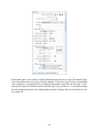
A shock loss resistance may be added to any branch in the ventilation model. A user defined
resistance may be added or a shock loss factor may be placed in the model to allow VNet to auto
calculate a shock loss resistance. To use a shock loss factor and auto calculate the resistance, the
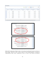
symbol next to “Shock Resistance” must be turned on . When off the icon has a red x mark
much the same as auto calculate area/perimeter or auto length tools.
In order for VNet to calculate the shock loss resistance, users must define three parameters; airway
cross-sectional area, average mine air density, and Shock Loss Factor. The cross-sectional area is
user defined for each branch in the Branch Data View or the Branches view. The area may be
either input manually or calculated based on the profile type dimensions directly above the area
cell in the Branch Data View. To calculate the area from the cross-sectional area dimensions, the
user will need to check the box labeled Area/Perimeter Auto Calculate. If the user changes the
cross-sectional area after calculating the Shock Resistance, VNet will recalculate the shock loss
resistance and update the value automatically.
The average mine air density is user defined on the Model Information view. Shock loss (X) factors
may be defined as the number of velocity heads that give the frictional pressure loss due to
turbulence at any bend, variation in cross-sectional area, or any other configuration that causes a
change in the general direction of airflow. Users may select Reference for additional information
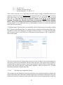
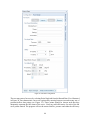
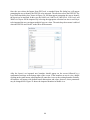
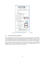
for selecting a Shock Loss Factor. After users enter a shock loss factor the calculated shock loss
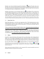
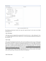
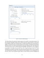
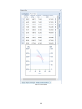
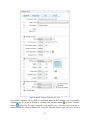
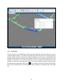
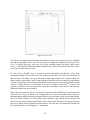
resistance will appear in the Branch Data View. An example of this is displayed in Figure 10.
Figure 10: Shock Loss Factor Entry Box
3.11.1.8
Parallel Branch Tool
A tool is available to allow the user to rapidly adjust the resistance of a branch according to parallel
network theory. This tool is accessible in both the Branches view (Parallel Factor column) and in
Branch Data View > Parallel Factor. The user may enter a number, with the default being 1. If the
user selects a 2, then the code will adjust the input branch resistance to double the number of
airways represented by the branch. If the user were to enter 0.5, then the resistance would be
27